

Page 1

WebVision™
CAUTION
USER GUIDE
PRODUCT DESCRIPTION
WebVision™ is a web-based building manager that allows
contractors and facility managers to view and command
HVAC controllers installed at their sites. It communicates over
the LonWorks
control of various devices and controllers through a web
browser. The WebVision Bundle (WWS-VL1A1000) includes
the WebVision controller pre-installed with a LON
communications card, and power supply.
WebVision is capable of:
• Discovering unitary controllers connected to WebVision
• Configuring controllers using configuration wizards
• Monitoring, raising, and e-mailing alarms on controller
points and system events
• Configuring and collecting trends on points
• Driving scheduled occupancy states
• Managing energy through Demand Limit Control (DLC)
• Providing single point of entry into the system to perform all
the above mentioned tasks.
• Managing access to information through user privileges
• Providing IT-friendly network interface for easy access and
management
WebVision acts as an offline configuration tool that helps the
contractor to configure site project that consists of multiple
unitary controllers. The contractor can commission all the
controllers by connecting through a LAN, WAN, or Dial-up.
WebVision also acts like a network time master to synchronize
time and date in devices connected to it with its own time and
date or with the Internet time servers. Its Device Discovery
feature enables you to discover online devices. You can
manage users and control their access to different resources
in the system. The System Administrator can configure
network settings, site information settings, system and control,
network data and time settings, and new module installation.
®
network to perform building management
Approvals
UL 916, C-UL listed to Canadian Standards Association (CSA)
C22.2 No. 205-M1983 “Signal Equipment”, CE, FCC part 15
Class A, C-tick (Australia)
Make sure that there is not more than one
WebVision accessing the same Lon
simultaneously. If more than one WebVision
accesses the same Lon network simultaneously,
there may be problems in downloading and
uploading parameters.
NOTE: WebVision is compatible with Microsoft
Explorer
resolution is 1280x1024 pixels.
IMPORTANT
Make sure that there is only one WebVision
accessing the L
time. If more than one WebVision accesses the
same LONWORKS network simultaneously, ensure
that its logical address is unique in the network to
avoid address conflicts. For a L
logical address refers to Subnet/NodeID.
®
(IE) 6.0 SP2 or higher. Suggested screen
ONWORKS network at a given point in
®
network
®
Internet
ONWORKS network,
Contents
Product Description ....................................................... 1
Features .......................................................................... 2
Operation and Use ......................................................... 2
Warranty and Returns .................................................... 33
Appendix A – Supported Devices ................................. 34
Appendix B – Device Point Tables ............................... 106
Topic Index ..................................................................... 175
95-7769-01
Page 2
WEBVISION™
FEATURES
• Support up to 120 XL10s, XL15Cs, VFDs, and 3rd Party
LON devices
• Perform Auto Discovery and Wizard based
configuration of controllers
• Support Default Alarms on each device
• Support Default Trends on each device
• Support default device graphic for each device
• Configure a maximum of 30 users and define their
roles in accessing and configuring devices and
WebVision
• Configure a maximum of 50 schedules
• Configure and schedule device occupancy
states
• Assign up to 120 devices per schedule
• Configure a maximum of 100 trends
• Store up to 1,000 samples per trend
• Configure up to 100 user defined alarms
• Store and view up to 5,000 alarm records
• E-mail alarm messages can be sent to a
maximum of 50 e-mail addresses
• Configure up to 50 loads for Demand Limit Control
• Configure default and up to 50 user-defined graphics
with support to command-able points
WebVision is built on Niagara-AX™ technology and extends
the capabilities of WebStat™.
2. Type your WebVision login name in the User Name
field.
3. Type your Password.
4. Click Login or press Enter. The Properties page
appears.
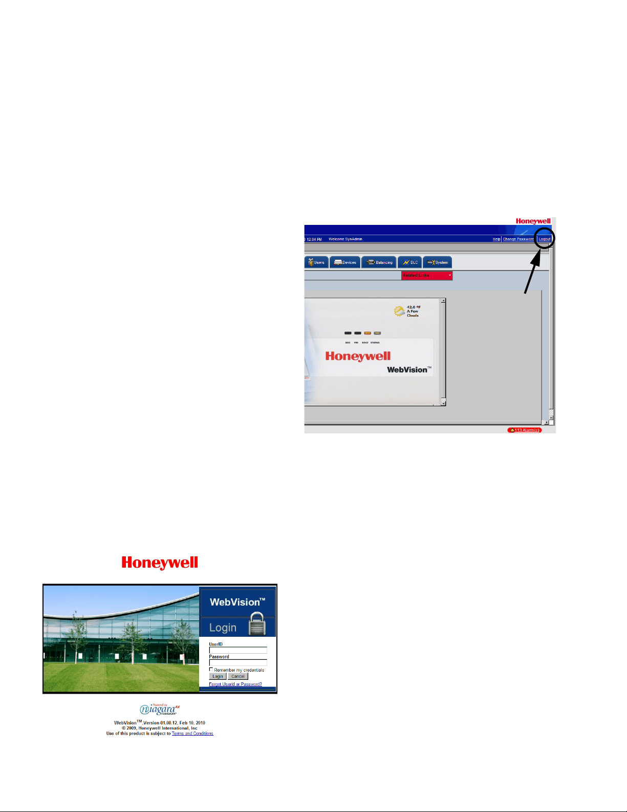
To log off from WebVision:
— Click the Logout link located on the right top of your
screen to log off from WebVision. You are redirected to
the WebVision Login page.
OPERATION AND USE
This section describes how to use the WebVision controller.
Sign-in
To log on to WebVision:
1. Type the WebVision web address (URL) in the Address
field of Internet Explorer
appears.
®
. The WebVision Login page
Fig. 2. Logout Link.
Password Reminder
To be reminded of your UserID or Password, if you have
forgotten either of them, perform the following:
1. Type the WebVision web address (URL) in the Address
field of Internet Explorer. The WebVision Login page
appears.
2. Click Forgot UserID or Password? link on the Login
page.
You are directed to the Password Reminder screen.
3. Select your secret question (the one you selected while
creating your user account).
4. Enter the answer to the Password Reminder Question
(you are expected to enter the same answer that you
gave while creating your user account).
5. Enter your E-Mail ID (same as in your user account).
WebVision looks for account that matches the secret
question, the answer to the question, and the e-mail Id.
After validating, it sends the user Id/password to that
e-mail Id.
6. Click Submit.
Fig. 1. Login page.
95-7769—01 2
Page 3
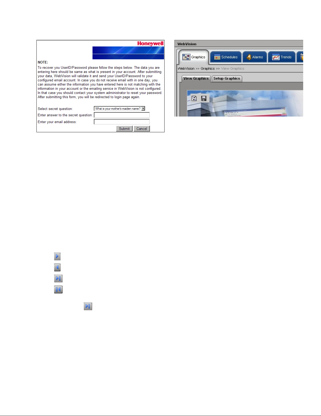
Fig. 3. Password Reminder screen.
TIP: The information you provide is validated against the
information present in the WebVision database. If the
information is correct, WebVision will send the user ID
and password to your E-Mail account.
TIP: If you do not remember the password recovery
information and the answer provided by you is incorrect,
you can request the WebVision Administrator to reset
your password. In any other case, please contact the
Honeywell Support for assistance.
Working with Tables
Click the column header of a column that you want to sort in
ascending/descending order. Columns that you can sort are
distinguished by an underlined column header. Tables are, by
default, displayed in ascending order. However, for alarms,
default display is in the reverse chronological order (the most
current alarm is displayed on top).
• Click to move to the next page.
• Click to move to the previous page.
• Click to move to the last page.
• Click to move to the first page.
• Type the number of rows you want to view on each page in
the text box next to .
• Type the page number that you want to navigate to in the
Page field. This enables you to quickly move to the page of
your interest without having to wade through all intervening
pages.
Graphics
A graphic is a pictorial illustration of a building's layout
coupled with the placement of various devices within a
building. With the help of a graphic you can view the various
devices installed in your building.
WEBVISION™
Fig. 4. Graphics Tab.
There are 3 locations in the WebVision where you can view
and setup graphics. These are:
• Network Tree > WebVision Node (Max 1 Graphic)
• Network Tree > Device Node. One graphic for each device.
This is the default device graphic. You can add a maximum
of three links on the graphic pointing to an external URL or
to another graphic.
• Location Tree. You can create user defined location
hierarchy (as tree). For each location (tree node), there can
be one user defined graphic. You can customize the
graphic and set a background image, monitor and
command points, add links to external web sites, and add
links to a different graphic.
You can insert the following in a graphic:
• Background images
•Points
•Devices
•Text
• External Links
• Links to other graphics
NOTE: Apart from the Contractor (who has all the privileges
in WebVision) all the users who add/replicate new
graphics have access to all the graphics created by
them.
To view a graphic:
1. Click the Graphics tab. The View Graphics page
appears.
2. Select the graphic you want to view from the list. The
selected graphic appears.
To setup a graphic:
1. Click the Graphics tab. The View Graphic page
appears.
2. Click Setup Graphics. The Setup Graphics page
appears.
Use the following options to configure graphics:
TIP: Move the pointer over any button. A tool tip appears
describing the action performed by the button.
3 95-7769—01
Page 4
WEBVISION™
To insert a background image:
NOTE: The supported background image formats include:
jpg, jpeg, and gif.
The size of the image file must not exceed 1MB.
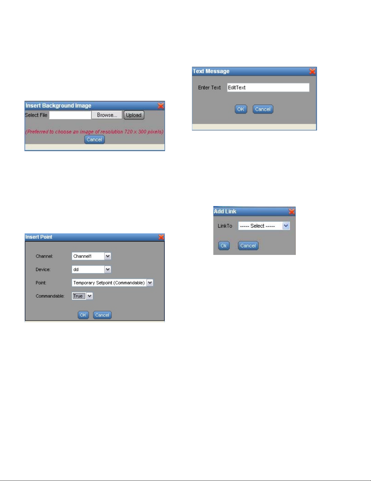
1. Click the Insert Background Image button. The Insert
Background Image dialog box appears.
Fig. 5. Insert Background Image dialog box.
2. Browse and select an image that you want to use as
background image.
3. Click Upload to insert the image.
NOTE: To abort the action, click Cancel.
To insert a point:
1. Click the Insert Point button. The Insert Point dialog
box appears.
To insert text:
1. Click the Insert Text button. A Text Message box
appears.
Fig. 7. Text Message Box.
2. Type the required text in the Edit Text field.
3. Click Save to reflect the changes in the image.
NOTE: To abort the action, click Cancel.
To insert an external link:
1. Click the Insert External Link button. The Add Link
dialog box appears.
Fig. 6. Insert Point dialog box.
2. Select the Channel, Device, and Point that you want to
add to the graphic from the corresponding drop-down
lists.
3. Click OK. The Point properties are displayed in the
background image.
NOTE: To abort the action, click Cancel.
Fig. 8. Add Link dialog box.
2. Select a link from the Link To drop-down list. You can
select from Device Graphics, Locations Graphics, or an
External URL.
3. If you select the Device Graphics option, the Insert
Device dialog box appears. Select a Channel and
Device and click OK.
4. If you select the Locations Graphics option, the Add
Link dialog box appears. Check the locations that you
want to add as link and click OK.
5. If you select the External URL option, the Insert
External Link dialog box appears. Type the Display
name for the url and type the url in the URL field.
6. Click OK to view the URL in the image.
NOTE: To abort the action, click Cancel.
NOTE: A maximum of fifty links can be inserted in a graphic
in WebVision.
95-7769—01 4
Page 5
WEBVISION™
To delete selected objects:
1. Select the object that you want to delete from the
graphic.
2. Click Delete Selected objects. The selected object is
deleted.
To copy graphics:
1. Click the button. The Copy Graphics From dialog
box appears.
2. Click Delete Selected objects. The selected object is
deleted.
Schedules
Schedules define the days and times when an occupancy
event must occur. Schedules are weekly calendars for
occupancy mode changes. Schedules also contain special
event information such as holidays or unplanned events.
NOTE: You can have a maximum of 50 schedules in
WebVision.
You can create, modify or delete a schedule only if you have
these privileges assigned to you.
There are three occupancy modes:
• Occupied – A period of time when the controlled
environment is considered to be occupied. It requires a
closer control for comfort, health, and safety.
• Unoccupied – A period of time when the controlled
environment is considered to be unoccupied. It is used to
reduce energy consumption.
• Standby – A period during the normal occupied period
when the space may not be occupied. It is used for energy
saving programs.
• No Event – WebVision displays the default state as
Occupied when no event is configured.
Use one of the following filter options to search for the
required schedule:
• Schedule Name
• Current Occupancy State
TIP: To quickly search the schedules, type the first letter of
schedule name or occupancy state, (as the case may
be) in the Keyword text box and type *. This lists all the
names starting with the first letter that you have written
in the Keyword text box.
• Schedule Name – Indicates the name of the schedule.
• Schedule Type – Indicates if the schedule is configured in
the local system or followed from a remote system.
• Current Occupancy State – Indicates the occupancy state
as defined by the schedule at the moment.
NOTE: A maximum of 100 devices can be assigned to a
schedule.
• Next Occupancy State – Indicates the occupancy state for
the next defined schedule.
• Time Remaining (minutes) – Indicates the time remaining
in switching to next occupancy state.
• Replicate – Click Replicate to replicate the settings.
Add/Edit Schedules
You can add a maximum of 50 schedules.
NOTE: All fields marked with an asterisk (*) are mandatory.
To create a new schedule:
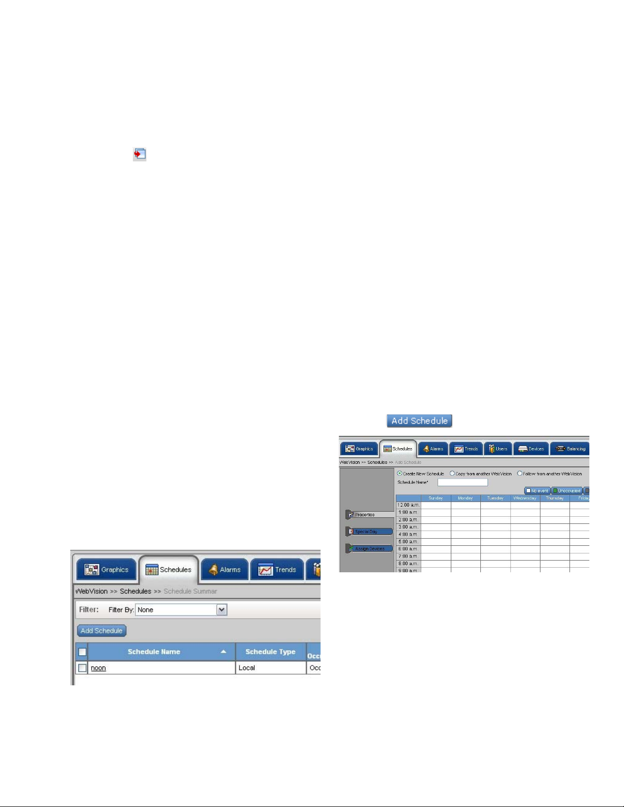
1. Click the Schedule tab. A list of schedules appears.
2. Click . The Properties page appears.
NOTE: Apart from the Contractor (who has all the privileges
in WebVision) all the users who add new schedules
have access to all the schedules created by them.
To view schedules:
1. Click the Schedule tab. A list of schedules appear with
the following details in a tabular format:
Fig. 9. Schedule Tab.
TIP: Use Filters to quickly search the required Schedules.
Fig. 10. Schedule Properties page.
3. Select the Create New Schedule option.
4. Type a schedule name in the Schedule Name field and
provide a description in the Description field.
5. Select the cells by dragging over the cells. Cells can be
selected horizontally and vertically. After selecting the
cells, click on the schedule occupancy state button to
indicate the state on the selected cell.
6. Click Apply to apply the schedule.
7. Click Finish to save the settings.
NOTE: Click Edit Time and type the Start Time and End
Time. You can change the start and end time of the
selected area.
5 95-7769—01
Page 6
WEBVISION™
To edit a schedule:
1. Click the Schedule tab. A list of schedules appears.
2. Click the schedule that you want to edit by clicking the
corresponding link in the Schedule Name column.
3. Follow the steps described in the above sections and
make the required changes.
Assign Devices
You can select a number of devices and assign them to a
current configuring schedule. You can change the settings as
and when required.
To assign devices:
1. Click the Schedule tab. The Schedule page appears.
2. Go to Add Schedule. The Add Schedule page
appears.
3. Type a unique name for the schedule.
4. Click Assign Devices. The Assign Devices page
appears.
5. Check the devices from the Device Name list that you
want to assign to the current schedule.
All the devices that are already assigned to schedules
are listed in the Currently Assigned Schedule column.
If a device is already assigned to a schedule,
WebVision un-assigns the device from the earlier
schedule and assigns it to the current schedule.
6. Click Finish to save the settings.
All the special events along with a summary appear in a
tabular format.
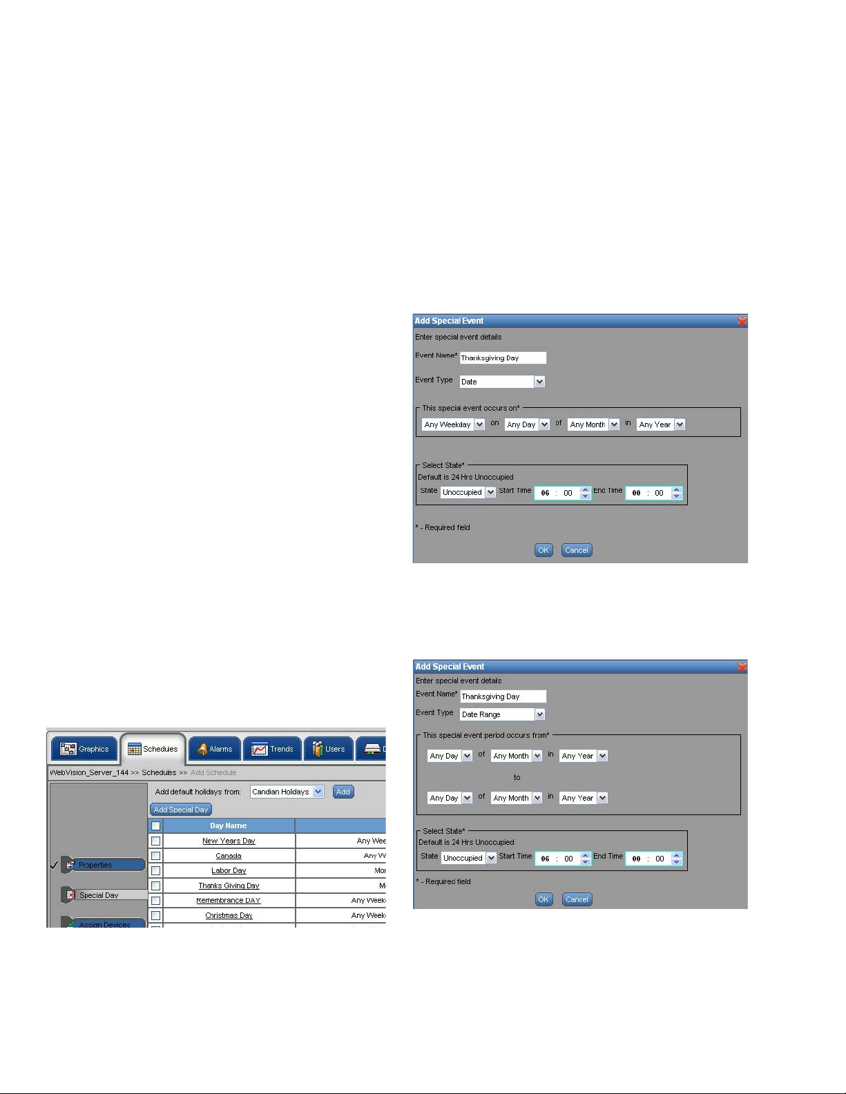
2. Click Add Special Event, to add new special events to
the list. The Add Special Event dialog box appears.
3. Enter/select the following information:
• Event Name – Name of the special event.
Example: Thanksgiving Day.
• Event Type – You can define the type of day using
the three options given: Date, Date Range, and
Week and Day. Depending on the selected criteria,
you get the following output:
Date – If you select Date, specify the day, date,
month, and year.
NOTE: To abort the action, click Cancel.
Define Special Event
Holiday schedules and schedules for special events differ
from the normal days. You can define schedules for special
events using WebVision.
NOTE: You can define any number of special events in a
schedule.
To define a schedule for special events:
1. Click Special Event on the Properties page. The
Special Event page appears.
Fig. 12. Add Special Event dialog box.
Date Range – If you select Date Range, specify the date
range, month, and year (Fig. 13).
Fig. 11. Schedule Properties page - Special Event.
95-7769—01 6
Fig. 13. Add Special Event dialog box - Date Range.
Page 7
WEBVISION™
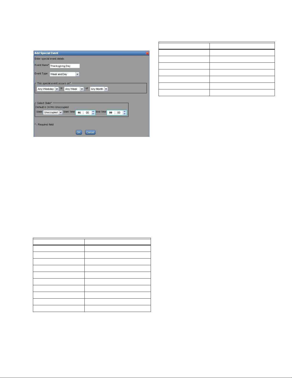
Week and Day – If you select Week and Day, specify the
month, week, and year (Fig. 14).
Fig. 14. Add Special Event dialog box - Week and Day.
4. Enter/select the following information under Select State
• State – Occupied, Unoccupied, and Standby.
• Start Time – The time to start the special event.
• End Time – The time to end the special event.
Table 2. Default Canadian Holidays.
Name Day
New Year’s Days January 1st
Canada Day July 1st
Labour Day The first Monday in September
Thanksgiving Day The second Monday in October
Remembrance Day November 11th
Christmas Day December 25th
Boxing Day December 26th
To add the pre-configured holidays:
1. Select the US Calendar or Canadian Holidays using the
drop-down list on the Special Event page.
2. Click Add. The selected (US or Canadian) preconfigured list of holidays is added and is displayed in
tabular format.
IMPORTANT
Special events are not executed if you commit an
error in specifying them. WebVision cannot validate
the dates you enter for a special event. No error is
shown if you configure wrong dates for special event,
provided the dates are in the specified format.
NOTE: By default the occupancy state is 24 hours
Unoccupied.
5. Click OK to save the settings.
NOTE: Click Cancel to close the window without saving the
changes.
Default holiday list
Table 1 and Table 2 list the default holidays for the US and
Canada.
Table 1. Default US Holidays.
Name Day
New Year’s Days January 1st
Martin Luther King Jr. Day The third Monday in January
Presidents Day The third Monday in February
Memorial Day The last Monday in May
Independence Day July 4th
Labor Day The first Monday in September
Columbus day The second Monday in October
Veterans Day November 11th
Thanksgiving Day The fourth Thursday in November
Christmas Day December 25th
Delete Schedules
To delete a schedule:
1. Click the Schedule tab.
2. Select the check box corresponding to the schedule you
want to delete from the Schedules Name list.
3. Click Delete. A confirmation message appears.
4. Click OK to confirm the deletion.
NOTE: Click Cancel to cancel deletion.
TIP: To delete all schedules at once, check the All check box
in the header and click Delete.
Replicate Schedule
You can replicate one schedule at a time. A maximum of 10
copies of the selected schedule can be replicated. Click
Replicate to replicate that schedule.
To replicate a schedule:
1. Click the Schedule tab.
2. Click Replicate. The Replicate Schedule box is
displayed.
3. Enter the number of copies that you want to create.
4. Add a prefix or suffix to the new replicated schedule's
name in the Label text box.
5. Click OK to confirm the replication.
NOTE: Click Cancel to cancel replication.
7 95-7769—01
Page 8
WEBVISION™
Alarms
Viewing alarms
A device configured with alarm settings is set when the value
of a point satisfies the alarm condition of that device.
Use the Alarms tab to view and acknowledge alarms that are
raised on various devices. You can filter alarms based on
occurrence, acknowledgment status, ack time, RTN time,
priority, and so on. You can setup alarms, define their limits,
and prioritize them. You can also acknowledge alarms and
delete acknowledged alarms.
Alarm priorities can be set for each type of alarm condition.
The alarm priority can range from 1 to 10 and is used to
determine E-Mail alarm message recipients. High priority
alarms have a higher reporting priority. For example, system
alarms (for example, low battery) are always high priority.
E-Mail alarm messages can be sent to a maximum of 50 EMail addresses. Any E-Mail alarm message can be sent to
any combination of 50 E-Mail addresses based on the priority
assigned.
When you add a device, all the default alarms present in that
device are added to WebVision. All the default alarms are
enabled.
NOTE: Select the check box in the header row to select all
the listed alarms.
• Alarm Name – List of all alarm names.
• Device Name – Lists all devices on which alarms are set.
To view the details of any device, click the respective
device.
• Description – Indicates the condition that raised the
alarm.
• Occurrence Time – Indicates the date and time when the
alarm was raised.
• Priority – Indicates the priority level of an alarm. There are
ten priority levels defined in WebVision - 1 through 10. 1 is
low and 10 is the highest priority level.
• Alarm State – Indicates alarm acknowledgement status.
• Acknowledged by – Indicates the user who acknowledged
the alarm.
• Acknowledge Time – Indicates the date and time when
the alarm was acknowledged.
• Return to Normal Time – Indicates the date and time
when the alarm returned to the normal condition.
TIP: Check the Enable Auto Refresh check box to enable
the auto refresh feature. The page is refreshed every 30
seconds.
To acknowledge an alarm:
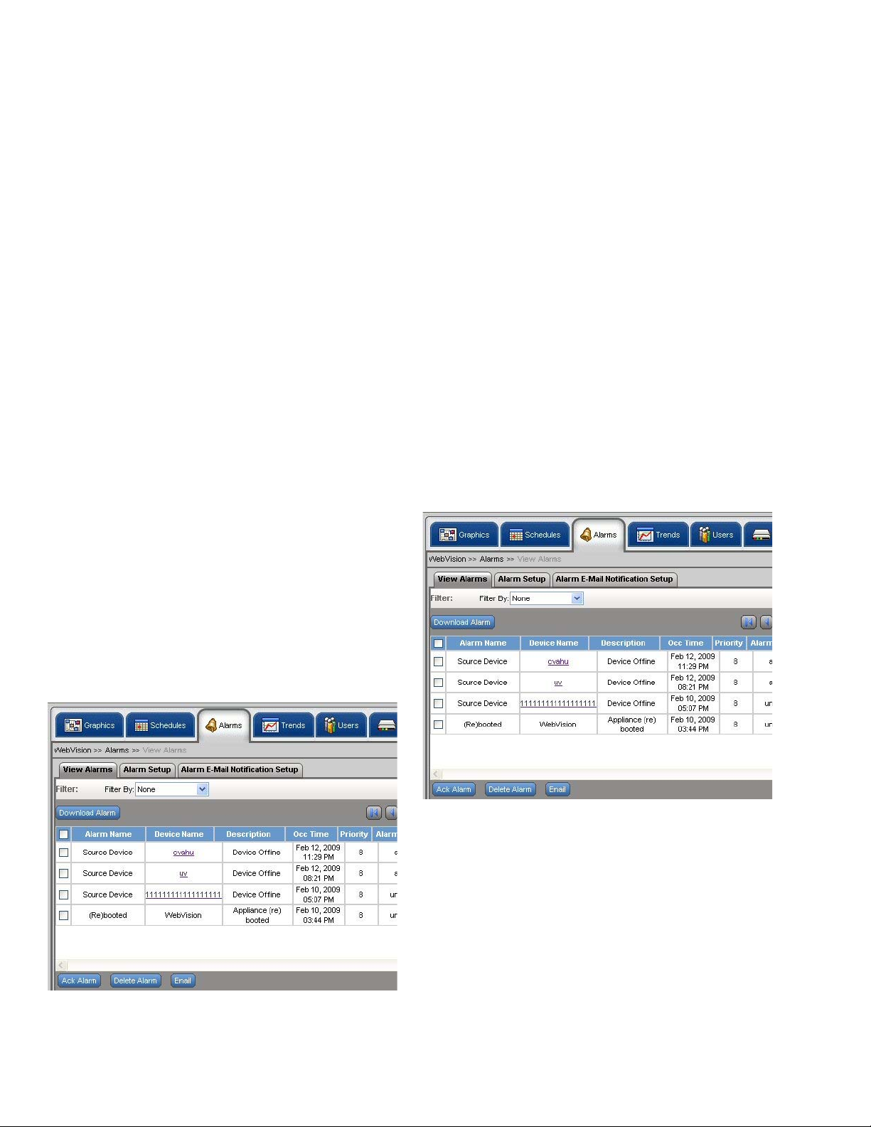
1. Click the Alarms tab. The View Alarms page appears.
An alarm is raised when the value of a point on a device on
which an alarm condition is configured satisfies the alarm
condition. The View Alarms page displays a list of alarms
raised on devices along with information such as description
of the alarm, occurrence time of the alarm, the time when the
alarm was acknowledged, return to normal time, the priority of
the alarm, and so on.
To filter and view alarms:
1. Click the Alarms tab. The View Alarms page appears.
The following information appears in a tabular format:
Fig. 16. View Alarms page.
2. Select the check box corresponding to the alarm you
want to acknowledge.
3. Click Ack Alarm.
4. The alarm is acknowledged. The time and date when
the alarm is acknowledged appears in the Ack Time
column. The user name is displayed in the Ack By
column.
Fig. 15. Alarms Tab.
95-7769—01 8
TIP: Select the check box in the header row to select all the
alarms for acknowledgment simultaneously.
Page 9
WEBVISION™
Exporting Alarms
You can export alarms on WebVision.
To export alarms:
1. Click the Alarms tab. The View Alarms page appears.
2. Click Export All Alarms to download all the alarms at
once.
3. A .csv file is displayed.
4. Click Open to open the file and click Save to save the
file on your computer.
To E-Mail alarms:
1. Select the alarms you would want to e-mail by clicking
the corresponding check boxes.
2. Click E-Mail. An Enter Email Addresses box is
displayed. Enter a list of e-mail addresses to which the
selected alarms must be E-Mailed. The list must be
separated by a semicolon (;).
3. Click Ok. The selected alarms are E-Mailed to those
recipients.
Alarm Configuration and Use
To add new alarms:
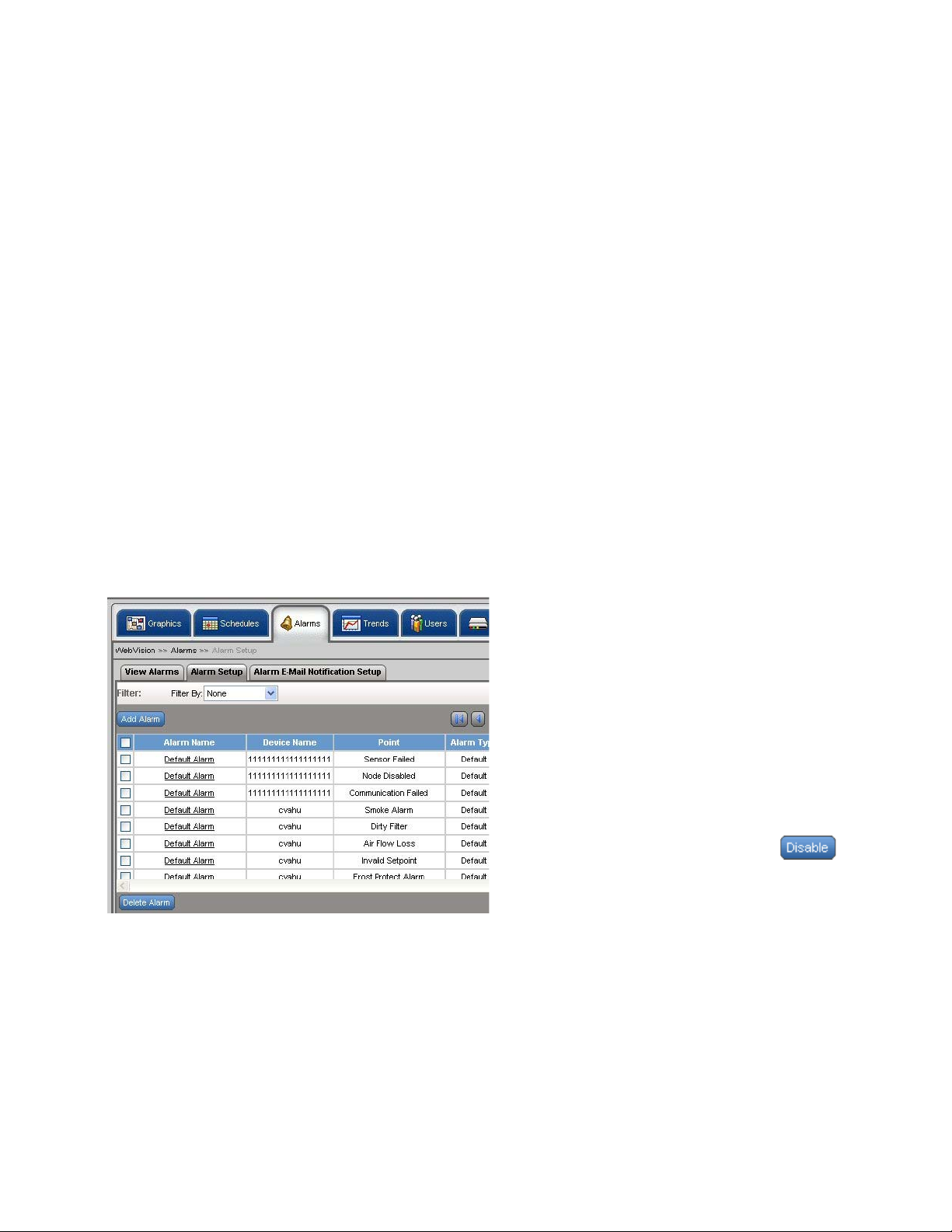
1. Click the Alarms tab. The View Alarms page appears.
2. Click the Alarm Setup tab on View Alarms page. The
Alarm Setup page appears.
down list. The selected values are reflected in
the Alarm Setup screen. Type a Display Name
for the point.
NOTE: The alarm condition depends on the type of selected
point. If it is a numeric point, you must provide Alarm
High Limit and Alarm Low Limit. If it is a discrete
value (Enumerated or Boolean) point, then select an
alarm value in the possible point value list in the
combo box.
Example: For Occupancy State, you can select alarm value as
Unoccupied in which case WebVision raises an alarm
whenever the point has Unoccupied as its value.
• Select Alarm value – This option is available for
enum and boolean values. Select the required
alarm value from the drop down list.
• Limits:
• High Limit – Select or type the higher limit of a
device beyond which an alarm is raised.
• Low Limit – Select or type the lower limit of the
device below which an alarm is raised.
NOTE: For numeric values, Limits are listed and for enum
and boolean values the Select Alarm Value is listed.
• Description – Description of the alarm.
• Set Priority As – Indicates the priority of the
alarm. Set 1 for low priority and 10 for High
priority. It can be Low, Medium, or High. Priority
is configured depending on the device's
configurations and settings
• Enable – Click Yes to enable the alarm along
with its configuration. Checking this option,
displays the alarm in the View Alarms page.
Click No to disable the alarm.
5. Click Save to save the settings.
Fig. 17. Alarm Setup page.
3. Click Add Alarm. The Add Alarm page appears.
4. Enter the Alarm Name and select the desired Points:
• Alarm Name – The name of the alarm.
•Select Points:
• Channel – The selected channel.
• Device – The selected device.
• Point – The selected point.
• Select Point – Click Select Point. The Select
Point dialog box is displayed. Select a Channel,
Device, and Point from the corresponding drop
To edit an alarm configuration:
1. Select an alarm from the alarm's list to edit it. The
selected alarm's details appear.
2. Modify the required fields as described in step 4 of “To
add new alarms:”.
3. Click Save to save the settings.
NOTE: You can enable or disable an alarm from the Alarm
Setup screen. For example, click from the
table on the Alarm Setup page to disable an alarm.
To delete an alarm:
1. Click the Alarms tab. The View Alarms page appears.
2. Select the check box corresponding to the alarm you
want to delete.
3. Click Delete Alarm. A confirmation message appears.
4. Click OK to confirm the deletion.
NOTES:
1. Click Cancel to cancel the deletion.
2. Only Acknowledged Alarms can be deleted.
TIP: To delete all alarms at once, select the Alarm Name
check box and click Delete Alarm.
9 95-7769—01
Page 10
WEBVISION™
To replicate an alarm:
1. Click the Alarms tab. The View Alarms page appears.
2. Click the Alarm Setup tab on the View Alarms page.
The Alarm Setup page appears.
3. Click corresponding to the alarm that you want to
replicate. The Replicate Alarm dialog box appears.
4. Type the alarm name in the Alarm Name text box.
5. Select an alarm and device that you want to replicate
from the Replicate Alarm and Device drop-down list.
6. Choose a prefix or suffix to name the replicated copy of
the alarm. Select the Prefix with or Suffix with option as
required.
7. Type a label name for the alarm in the Label text box.
8. Click Replicate to confirm the replication.
NOTE: Click Cancel to cancel the replication.
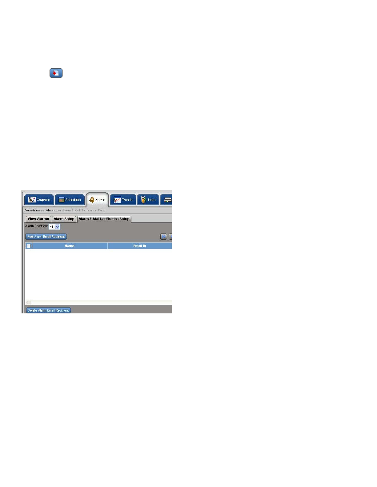
To setup alarm E-Mail notification:
1. Click the Alarms tab. The View Alarms page appears.
2. Click the Alarm E-Mail Notification Setup tab on the
View Alarms page.
Add, Edit, or Delete Alarm E-Mail Recipient
To add an alarm E-Mail recipient's details:
1. Click the Alarms tab. The View Alarms page appears.
2. Click the Alarm E-Mail Notification Setup tab on the
View Alarms page. The Alarm E-Mail Notification
Setup page appears.
3. Click Add Alarm E-Mail Recipient. The Add Alarm
E-Mail Recipient page appears.
4. Select the recipient type using the Select Recipient
Type drop-down list.
• For an External recipient, enter:
• Recipient Name – Name of the recipient.
• Recipient E-Mail ID – E-Mail ID of the recipient.
• For an Internal recipient, enter:
• Select User – Select the type of the user using
the drop-down list.
5. Select the alarm priorities that must be informed to the
recipient. Check the Select All check box to select all
the alarm priorities.
6. Click Save to add a new recipient.
NOTE: Click Cancel to abort the action.
To edit an alarm E-Mail recipient's details:
1. Click the Alarms tab. The View Alarms page appears.
2. Click the alarm name that you want to edit. The Alarm
Setup page of the selected alarm appears.
3. Edit the fields as explained in step 3 of “To add an alarm
E-Mail recipient's details:”.
4. Click Save to save the changes.
Fig. 18. Alarm E-Mail Notification Setup Tab.
3. The Alarm E-Mail Notification Setup page appears
with the following information in the tabular format:
TIP: Select the check box in the header row to select all the
listed alarms e-mail recipients.
• Name – Lists names of the users who will receive
the alarm E-Mail notification.
• E-Mail ID – Lists the E-Mail IDs of the
corresponding users.
• Recipient Type – Lists the type of user.
• Associated Alarm Priorities – Lists the alarm
priorities associated to the corresponding user if the
user is external. Alarm priorities range from 1 to 10.
1 being the lowest priority level and 10 being the
highest priority level. Check Select All to select all
the alarm priorities.
NOTE: Click Cancel to abort the action.
NOTE: The alarm priority information for internal user is
available in the user account configuration page.
To delete an alarm E-Mail notification recipient:
1. Click the Alarms tab. The View Alarms page appears.
2. Click Alarm E-Mail Notification Setup. The Alarm EMail Notification Setup page appears.
3. Select a user from the Name list that you want to delete.
4. Click Delete to delete the selected recipient.
TIP: To delete all recipients at once, check the All check box
in the header and click Delete.
Trends
Trends depict the values of points over time in a graphical
format. Use the Trends tab to view trends for the selected
points over a period ranging from a day to a year.
You can store a maximum of 1000 samples per trend. By
default you can store 500 samples per trend. Once you cross
the limit, the oldest sample is overwritten and rolled over
based on trend configuration. Five trends can be plotted
simultaneously. For example, outside air temperature and
space temperature plotted for a period of one month.
A trend point can be a data point from any supported
L
ONWORKS network device. A data point can be used in
multiple trend configuration. There are few default sample
95-7769—01 10
Page 11
WEBVISION™
trends stored in WebVision. You cannot delete these sample
trends. However, you can create new trends. The trends
created by you are called User Defined trends.
When you add a device, all the default trends present in that
device are added to WebVision. All the default trends are
disabled.
You can create and view a maximum of 100 trends.
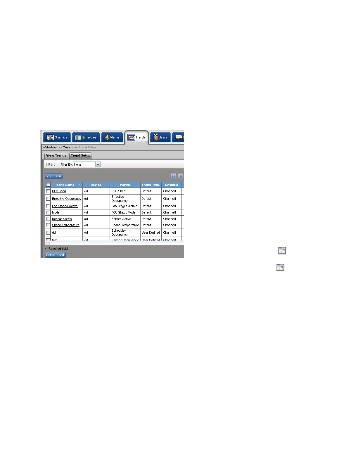
To view trends:
Click the Trends tab. The View Trends page appears with the
following information:
— Enable/Disable – Indicates if a trend is enabled or
disabled. Click the Enable or Disable buttons to
enable/disable the trend.
TIP: Use Filters to quickly search the required trend.
Use one of the following filter options to search for the
required trend:
• Channel Name
• Trend Type
• Trend Name
• Device Name
•Point Name
• Point Group
TIP: To quickly search the trends, type the first letter of the
required filter criteria in the Keyword text box and type
an asterisk (*). This lists all the names starting with the
first letter that you have written in the Keyword text box.
Plotting trends
NOTES:
1. A security warning message appears when you
access the Trends page and prompts you to
download the applet. Click Yes to continue.
2. A Java plug-in version 1.6 and above must be
installed to view the trend chart.
Fig. 19. Trends page.
— Tre nd Nam e – The unique name for the Trend.
— Device – Indicates the location on the device.
— Points – Indicates the points whose readings are
required to generate a trend.
— Trend Type – Indicates type of trend. For instance it
can be a user defined trend.
— Channel – Indicates the channel on which the devices
are present.
— Sampling Interval – Indicates the time interval
between two successive read operations on the point.
One hour is the default setting.
The sampling interval time can range from a few
minutes to a day. The range covered is:
• 15 seconds
• 30 seconds
• 60 seconds (1 minute)
• 900 seconds (15 minutes)
• 1800 seconds (30 minutes)
• 2700 seconds (45 minutes)
• 3600 seconds (60 minutes)
To plot a trend:
1. Click the Tren ds tab. The View Trends page appears.
2. Select a trend from the Configured Trends list to plot.
3. Click Plot Trend. The Plot Trend dialog box appears.
4. Enter the following parameters:
•Select Start Time – Click to select the start
date and enter the start time in hours and minutes.
•Select End Time – Click to select the end date
and enter the end time in hours and minutes.
NOTE: Start time must be less than the end time.
5. Click OK to view the graphical representation of the
trend or click Cancel to cancel the trend.
Viewing plotted trends
The view of the trends plotted have the following information:
• Plotted Trends – Lists the name of the trends that are
plotted.
• Start Time – Select the start time, if required.
• End Time – Select the end time, if required.
• Re-Plot Trends – After selecting the Start and End time
select this option to re-plot the trend with the new time
range.
• Download Trendlog – Click this button to download trend
log in .csv format for the plotted trends.
• Ok – Click Ok to go back to the View Trends screen.
11 95-7769—01
Page 12
WEBVISION™
Trend Setup and Use
TIP: You can enable or disable trends from the Trends Setup
screen.
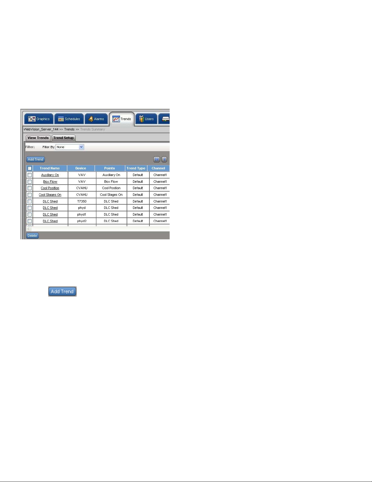
To setup a trend:
1. Click the Trends tab. The View Trends page appears.
2. Click the Trend Set up tab. The Trend Set up page
appears.
The sampling interval time can range from a few
seconds to a few minutes. The range covered is:
• 15 seconds
• 30 seconds
• 60 seconds (1 minute)
• 900 seconds (15 minutes)
• 1800 seconds (30 minutes)
• 2700 seconds (45 minutes)
• 3600 seconds (60 minutes)
• Change of Value – Indicates that the next sample
is collected when the point value changes. This
results in less number of samples getting collected
for plotting the same trend as compared to Periodic
Sampling. Change Tolerance is required only for
numeric points. Select a numeric point from the
Select Point option and type a tolerance value after
which the data logging begins.
• Trend L imit – Roll Over is the default selection.
This option trends the point forever.
• Roll Over – Indicates that the readings of
sampling are generated continuously. When the
sample limit is reached, the oldest sample is
replaced with the next sample and trending
continues in that fashion.
• Stop when full – Indicates that the trend
sampling is stopped after it reaches the set limit.
• Max number of Samples – The maximum
number of samples. Select the number of
samples to be generated from the list.
Fig. 20. Trend Setup tab.
To add a new trend:
1. Click the Trends tab. The View Trends page appears.
2. Click the Trend Set up tab. The Trend Set up page
appears.
3. Click . The Add New Trend page appears.
4. Enter/select the following details:
NOTE: All the fields in this section are mandatory.
NOTE: Start time must be less than the end time.
• Trend Nam e – The unique name for the trend.
• Select Point – Click Select Point. Select a Channel,
Device, and Point. Click OK. The selected values
appear in the respective fields.
• Start Time – The start time of the sampling period.
Click to select the date, month, and year
• End Time – Check Enable End Time to enable the
end time field. The end time of the sampling period.
Click to select the date, month, and year.
• Trend Type – Indicates the type of trend.
• Periodic Sampling – Indicates the time interval
between two successive read operations on the
point. Select Periodic Sampling option and in the
Sampling Interval list, select the desired time
interval.
NOTE: WebVision uses the polling mechanism to read point
values at regular interval. It may take up to 30
seconds to detect a point value. If the point value
changes at a higher frequency than 30 seconds,
WebVision may not be able to detect the changes.
5. Click Save to save the settings.
NOTE: Click Cancel to clear the fields.
To edit trends:
1. Click the Tren ds Se tup tab. The View Trends page
appears.
2. Select a Trend from the Trends list. The details of the
selected Trend appear.
3. Modify the required fields as described in step 4 of “To
add a new trend:”.
4. Click Save to save the settings.
NOTE: Click Cancel to cancel the settings.
To delete a trend:
1. Click the Tren ds tab. The View Trends page appears.
2. Go to Trends Setup. Select the trend that you want to
delete from the Trends listed on the left corner of the
screen.
3. Click Delete. A confirmation message appears.
4. Click OK to confirm the deletion.
NOTE: Click Cancel to cancel the deletion.
TIP: To delete all the trends simultaneously, select the check
box in the column header and click Delete Trend.
95-7769—01 12
Page 13

WEBVISION™
Users
You can create a maximum of 30 user profiles. You must be
familiar with User ID and Password security standards to
enforce user compliance when creating a user profile. As
WebVision is a secure server, you need to log in with a preassigned user ID and password. The user ID and password
combination determine your access level, which in turn
determine the kind of operator and configuration functions
performed.
The Network Administrator must be familiar with user ID and
password security standards and enforce user compliance.
The WebVision System Administrator can be accessed using
these initial default user ID and password: User ID SysAdmin and Password - !Sys!Admin.
It is a good practice to add one or more additional users with
Administrator access level to ensure top level access to
WebVision. Those with higher access levels have the
privileges of all the lower levels in addition to the privileges
unique to that level. These access levels are managed by the
System Administrator. There can be an individual or many
System Administrators who are assigned the task of
managing individuals at different access levels.
NOTE: For security compliance, it is mandatory to change
Use the Users tab to add users, assign devices to them and
define their privileges based on their roles. There are four
types of user roles (see Table 3):
• Contractor - Contractor is a user with all the privileges
• Facility Manager - This role represents a Building
• Tenant - The user assigned to this role has limited access
• Balancer - Balancer is a user who performs VAV Balancing
Role Matrix
See Table 3.
Privilege
your password after the initial login process. Once
changed, the default password will no longer work.
Exercise care to create a new password that meets
the security standards and can be easily
remembered by the System Administrator.
assigned and can perform all tasks. SysAdmin is a user
account with contractor privileges that cannot be deleted.
The privileges cannot be altered. This is to ensure that
there is at least one contractor available in the system.
Engineer who maintains HVAC equipment and monitors
the system with the help of WebVision.
to WebVision. The user with the Tenant role has access to
only those devices which are assigned to the user.
Job. The user assigned to this role has access to VAV
devices for WebVision.
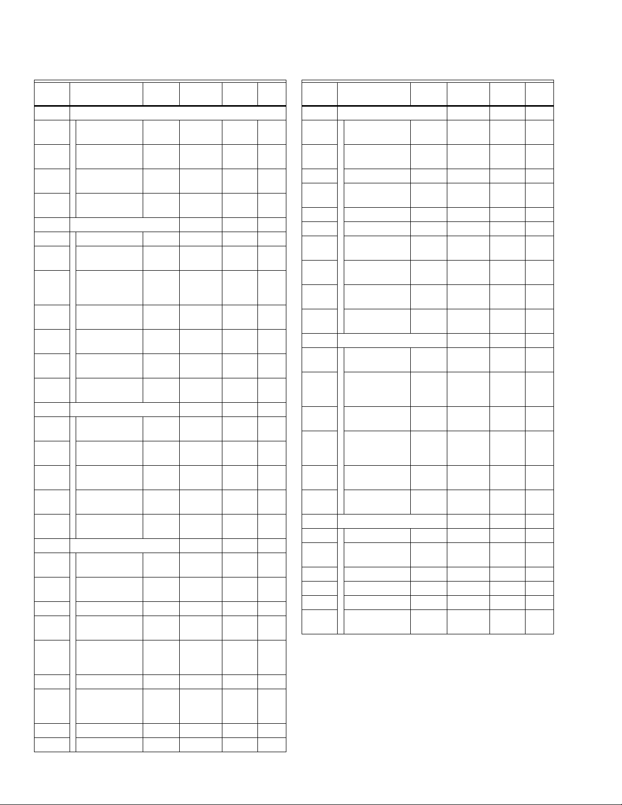
Table 3. Role Matrix.
ID Privileges
Depends
1
Graphics P
2 Change Controller
On Contractor
4PPP
Facility
Manager Tenant
a
PP
Setpoints
(temporary)
3 Override Schedule
4PPP
Occupancy
4 View Graphics P P P
Table 3. Role Matrix. (Continued)
Privilege
ID Privileges
Depends
On Contractor
Facility
Manager Tenant
Graphics (continued)
5 Edit Graphics 4 P
b
X
X
6 Add Graphics 4 P X X
7 Schedules PPP
8View Summary
PPP
Screen
9 View Schedule
9PPP
Configuration
10 Add Schedule
9PXX
Configuration
11 Edit Schedule
10 P P P
Configuration
12 Delete Schedule
9PXX
Configuration
13 Assign Devices to
9,11/12 P X X
Schedule
14 Alarms PPP
15 View Alarms
PPP
Summary
16 Acknowledge
16 P P X
Alarms
17 Delete Alarms 16 P X X
18 View Alarms
PPX
Configurations
Summary
19 View Alarm
19 P P X
Configurations
20 Add Alarm
19 P X X
Configurations
21 Edit Alarm
20 P P X
Configurations
22 Delete Alarm
19 P X X
Configurations
23 Download Alarm
16 P P X
Records as CSV
Files
24 Suppress Alarms 19 P P X
25 Setup Alarm E-
PPX
mail Notifications
26 View Priority 1
Alarms
27 View Priority 2
16
c
C
16 C C C
CC
Alarms
28 View Priority 3
16 C C C
Alarms
29 View Priority 4
16 C C C
Alarms
30 View Priority 5
16 C C C
Alarms
31 View Priority 6
16 C C C
Alarms
13 95-7769—01
Page 14
WEBVISION™
Table 3. Role Matrix. (Continued)
Privilege
ID Privileges
Depends
On Contractor
Facility
Manager Tenant
Alarms (continued)
32 View Priority 7
16 C C C
Alarms
33 View Priority 8
16 C C C
Alarms
34 View Priority 9
16 C C C
Alarms
35 View Priority 10
16 C C C
Alarms
36 Trends PPP
37 View Trend Graph P P P
38 Download Trend
38 P P X
Data CSV Files
39 View Trend
PPX
Configurations
Summary
40 View Trend
40 P P X
Configurations
41 Add Trend
40 P X X
Configurations
42 Edit Trend
41 P P X
Configuration
43 Delete Trend
40 P X X
Configuration
44 Users PP
45 View User
PPX
Summary
46 View User Account
46 P P X
Information
47 Add New User
46 P P X
Accounts
48 Edit User
47 P P X
Accounts
49 Delete User
46 P P X
Accounts
50 Devices PP
51 View Device
52 P P X
Summary
52 Discover Devices
52 P X X
on the Network
53 Add New Device 52 P X X
54 Copy an Existing
52 P X X
Device
55 Download/Upload
52 P P X
Device
Configuration
56 Delete Device 52 P X X
57 Invoke Device
52 P P X
Configuration
Wizard
58 Match Device 52 P X X
59 Change Setpoints 52 P P X
Table 3. Role Matrix. (Continued)
Privilege
ID Privileges
Depends
On Contractor
Facility
Manager Tenant
60 System PP
61 General
PPX
Configuration
62 IP Network
PXX
Configuration
63 Mail Configuration P P X
64 Change System
PPX
Date and Time
65 Upgrade Firmware P X X
66 Reboot System P P X
67 Download System
PPX
Load
68 Download Audit
PPX
Log
69 Network
PCC
Navigation
70 Physical
PCC
Navigation
71 WebSuite Network PP
72 View Appliance
PPX
Summary
73 Discover
73 P X X
Appliances on
Network
74 Add New
73 P X X
Appliance
75 Enable Network
73 P X X
Firmware at
Network Level
76 Change Master
73 P X X
Ownership
77 Change Network
73 P X X
User Password
78 DLC PP
79 Configure DLC P X X
80 View Load
PXX
Summary
81 Add Load 81 P X X
82 Delete Load 81 P X X
83 Edit Load 81 P X X
84 Monitor DLC
PPX
Status
a
The letter P means the role has that privilege.
b
The letter X means the role does not have that privilege.
c
The letter C means that the user can be given that privilege
when configuring his/her account.
95-7769—01 14
Page 15
WEBVISION™
View list of Users
The list of users provides information on WebVision users
such as their names, roles, and e-mail IDs.
To view the list of users:
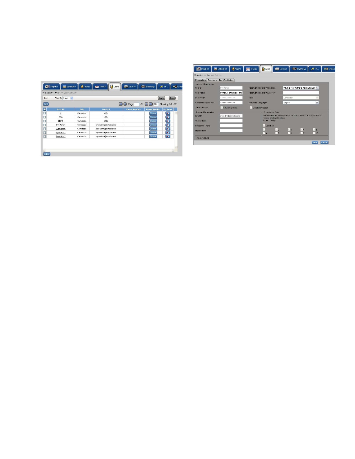
1. Click the Users tab. The Users page appears.
Fig. 21. Users page.
TIP: Use Filters to quickly search the required user.
Use one of the following filter options to search for the
required user:
•User ID
•Role
•Email ID
To add a user:
1. On the Users page, click the Add User button. The
Properties page appears.
Fig. 22. Add User - Properties page.
2. Enter the account information of the user:
• User ID – The unique user ID. It must have a
minimum of 6 characters.
TIP: You can use a maximum of 30 characters and a
minimum of 6 characters to set your user ID. The
permitted characters include a-z, A-Z, _, 0-9. The
following characters are not allowed: !, @, #, $, %, ^, *, , and |.
TIP: To quickly search the users, type the first letter of the
required filter criteria in the Keyword text box and type
an asterisk (*). This lists all the names starting with the
first letter that you have written in the Keyword text box.
2. The following information appears in a tabular format:
• User Name – Displays the name of the user name.
• Role – Displays the role assigned to the user.
• Email ID – Displays the user's e-mail ID for
communication.
• Phone Number – Displays the user's phone
number.
• Enable/Disable – Displays the user's status. Click
Enable to enable the user or Disable to disable the
user.
NOTE: Select the check box in the header row to select all
the users listed.
Add/Edit Users
While adding a user:
• Configure information related to User Name, Password,
Contact Information, and User Role Information through
the Properties tab.
• Assign Devices to the user being created using the Access
on this WebVision tab.
• Add new User only in the WebVision that is configured as
Network Server in networked WebVision.
• User Name – The user name.
• Password – Type your password.
TIP: You can use a maximum of 30 characters and a
minimum of 6 characters to set your password. The
permitted characters include a-z, A-Z, _, 0-9. The
following characters are not allowed: !, @, #, $, %, ^, *, , and |.
• Confirm Password – Retype your password.
• Password Recovery Question – Select the
Password Reminder Question.
• Password Recovery Answer – Type an answer for
the above question.
• Role – The role or designation of the user. Select
the role from the list.
• Show this user – The view authorized to the user.
• Network Sidebar – The user is authorized to view
only the network side bar view.
• Locations Sidebar – The user is authorized to view
only the locations view.
• Preferred Language – The user defined language.
Select the language from the list.
3. Enter the Personal Information of the user:
• Email ID – Type the user's e-mail ID.
• Office Phone – The user's office contact number.
• Residence Phone – The user's residence contact
number.
• Mobile Phone – The user's mobile contact number.
4. Set the Show Alarm Status. Select the alarm priorities
for which you want status update. The numbers are
listed from 1 through 10. The user can see only those
alarms whose corresponding priority is checked in this
step. Check Select All to view all the alarms
simultaneously.
15 95-7769—01
Page 16
WEBVISION™
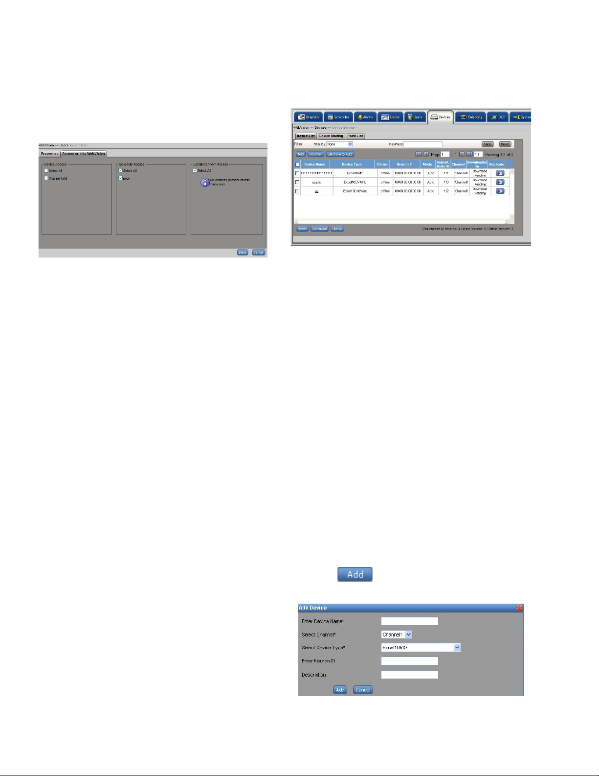
5. Click the Access on this WebVision tab. The Access
on this WebVision page appears. You can select
various options from Device Access, Schedule Access,
and Locations View Access. Check Select All to select
all the options simultaneously.
Use this option to assign customized access to users.
Fig. 23. Access on this WebVision page.
6. Click Save to save the user properties.
To edit a user:
Select a user from the User list, and make the required
changes as explained in the above section.
To delete users:
NOTE: Any user who has user management privileges can
add or remove a user.
1. On the Users page, click the name of the user you want
to delete from Users Name column.
2. Click Delete. A confirmation message appears.
3. Click OK to confirm the deletion.
IMPORTANT
SysAdmin is a user account with contractor
privileges that cannot be deleted. A SysAdmin's
privileges cannot be altered. This is to ensure that
there is at least one contractor available in the
system.
To enable/disable a user:
• Click Enable to enable a user.
• Click Disable to disable a user.
Devices
To view the list of devices:
1. Click the Devices tab. The Device List page appears.
The following information appears in a tabular format:
Fig. 24. Devices Tab - Device List page.
TIP: Use Filters to view the required list.
Use one of the following filter options to search for the
required device: Channel, Device Name, Device Type,
Status, Mode.
• Device Name – Name of the device.
• Device Type – Type of the device.
• Status – Status of the device, it can be online or
offline.
• Neuron ID – Each L
a 48 bit unique identifier, called the Neuron ID. This
is used to address the nodes on the LONWORKS
network.
• Mode – Mode of the device, it can be auto or
manual.
• Subnet/Node ID – A mask that is used to determine
the subnet of a network. Subnetting enables the
network administrator to further divide the host part
of the address into two or more subnets.
• Channel – The channel on which the device is
present.
• Synced On – Date and time on which the device is
last downloaded or uploaded.
• Replicate – Click Replicate to replicate the device
settings.
ONWORKS Controller node has
To add a device:
1. Click the Devices tab. The Device List page appears.
2. Click . The Add Device dialog box appears.
Enter the following details:
Device List
You can view all the devices present in WebVision. All the
information related to name, type, status, and so on is
available.
95-7769—01 16
Fig. 25. Add Device dialog box.
Page 17
• Device Name – Name of the device.
• Channel – The channel on which the device is
present.
• Device Type – Type of the device.
• Model – Type the model number of the device.
• Application Type – Type of application that is
required for the selected device.
• Application Version – Type the version of
application used.
• Application File – Application that must run on the
device. Click Browse to upload an application file.
• Neuron ID – The 48 bit unique identifier each
L
ONWORKS Controller node has. This is used to
address the nodes on a L
• Description – Description of the device.
NOTES:
1. All the fields marked with an asterisk (*) are
mandatory. However, it is advised to provide all
the information in the fields, so that WebVision
can provide more manageable features.
2. The above listed parameters form a
comprehensive list. The appearance of these
parameters vary depending upon the selected
device.
3. Click Add to add the device.
NOTE: Click Cancel to abort the action.
NOTE: To support 3rd party devices other than the
controllers listed in the dialog box, you must have a
corresponding Niagara LNML file that contains
information about the device and its points. This file
has to be uploaded while adding a device to
WebVision. WebVision allows you to create alarms
and trends on the 3rd party devices. WebVision
cannot drive the device's scheduled occupancy
state, do energy management using DLC, or do VAV
balancing for 3rd party devices.
ONWORKS network.
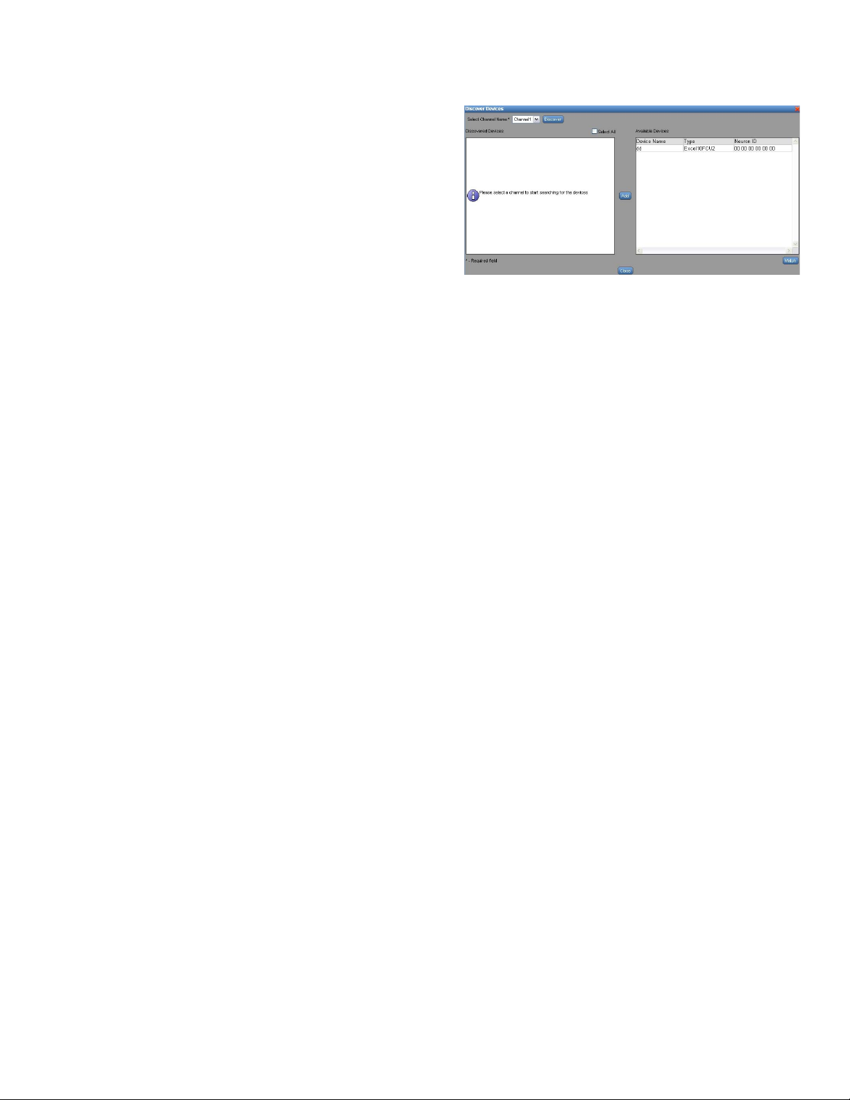
To discover devices:
You can discover the devices available on the network and
then add them to WebVision.
WEBVISION™
Fig. 26. Devices Tab - Device List - Discover button.
3. Select a channel on which you want to discover
devices.
4. Click Discover to start discovery. Once the discovery is
completed, WebVision lists the discovered new devices
on the left side list.
5. If you want to match a discovered device against an
existing device in WebVision, select the discovered
device on the left side list and select the existing device
on the right side list and click Match.
NOTE: Check the Select All check box to select all the
devices simultaneously.
6. Click Add to add discovered devices as new devices to
WebVision. The selected device gets added to the
Available Devices list.
7. Click OK to save the settings.
8. Click Log to view the discovery status.
NOTE: Click Cancel to abort the action.
NOTE: After discovering the devices you must upload the
device bindings to save the existing bindings onto
WebVision. This prevents you from losing the
existing binding, while downloading the new binding.
To upload, see “To upload device bindings:” on
page 19.
NOTE: Once a device is selected in the Discovered Device
table, only the matching device type in the Available
devices table is enabled for selection.
1. Click the Devices tab. The Device List page appears.
2. Click Discover. The Discover Device in the network
dialog box appears. The discovered devices are
displayed.
Deleting Devices
Deleting a device removes it from the device list as well as
from all other configurations such as trends, alarms, special
displays, DLC and schedules. Any alarms generated before
the device was deleted is still displayed on the Alarms page.
NOTE: You will not be able to see the deleted device in any
of the pages until it is discovered and added using
device add or discovery operation.
When you delete a device (that provides current power input),
the DLC service is disabled. All the alarms generated by a
device are available on the Alarms Summary screen.
However, the link present on the device fails, when the device
is deleted. Both trend configuration and trend data gets
deleted from the database.
To delete a device:
1. Click the Devices tab. The Device List page appears.
2. Select the devices that you want to delete by checking
the corresponding check box.
3. Click Delete to delete the devices.
17 95-7769—01
Page 18

WEBVISION™
4. Click OK to confirm the deletion.
TIP: To delete all devices at once, check the All check box in
the header and click Delete.
Set Mode to Auto
Sometimes when debugging a device, you set the mode to
manual. The Set Mode to Auto feature is a simple option to
set the devices back to auto mode.
To set the devices to auto mode:
1. Click the Devices tab. The Device List page appears.
2. Select the devices that you want to set to auto mode.
3. Click Set Mode to Auto to set the devices to auto
mode. A success message appears indicating that the
devices have been set to auto mode.
NOTE: Check the Select All check box to select all the
devices simultaneously.
Download Device Configuration
Once you have made all of the necessary configuration
settings to a device in WebVision, you will need to download
the configuration to the device.
To download a device:
1. Click the Devices tab. The Device List page appears.
2. Select the devices that you want to download by
checking the corresponding check boxes.
3. Click Download to download the selected devices. The
Downloading Device Information bar indicates the
progress of download.
4. Click Log to view the download status.
NOTE: Click Cancel to abort the action.
Upload Device Configuration
You can upload device configuration from a device on to
WebVision.
To upload configurations from a device:
1. Click the Devices tab. The Device List page appears.
2. Select the devices whose configurations you want to
upload.
3. Click Upload to upload the settings.
4. Click Log to view the upload status.
4. Choose a prefix or suffix to name the replicated copy of
the device. Select the Prefix with or Suffix with option as
required.
5. Type a label name for the device in the Label text box.
6. Click OK to save the settings.
NOTE: Click Cancel to abort the action.
Device Binding
Binding refers to a configured association either within a
device, or between separate devices on a L
network.
ONWORKS
To view a list of bound devices:
1. Click Devices on the WebVision page. The Device
List page is displayed.
2. Click Device Binding. The Device Binding page is
displayed.
NOTE: Select the required channel from the Select Channel
drop-down list.
3. The following information displays in tabular format:
• Source Device – Lists the source device involved in
the binding.
• Source Point – Lists the network object/point of the
source device that is involved in the binding.
• Target Device – Lists the target device involved in
the binding.
• Target Point – Lists the network object/point of the
target device that is involved in the binding.
• Link Status – Shows the binding status. The status
can be bound or unbound.
To add devices for binding:
1. Click Devices on the WebVision page. The Device
List page is displayed.
2. Click Device Binding. The Device Binding page is
displayed.
3. Click Add. The Add Device Binding box is displayed.
4. Select the following:
• Channel
• Source Device
•Source Point
• Target Device
• Target Point
5. Click OK. The binding is created in WebVision and has
to be downloaded to the controllers.
NOTE: Click Cancel to abort the action.
Replicate Devices
You can replicate existing devices in WebVision.
To replicate a device:
1. Click the Devices tab. The Device List page appears.
2. Click corresponding to the device that you want
to replicate. The Replicate Device dialog box displays
and the selected device displays in the Replicate
Device list.
3. Select the number of copies that you want to create
using the Number of copies to be created selection field.
95-7769—01 18
To delete bindings:
1. Click Devices on the WebVision page. The Device
List page is displayed.
2. Click Device Binding. The Device Binding page is
displayed.
3. Select a pair of bounded devices that you want to delete
and click Delete. The bindings in WebVision are
deleted. You have to invoke download to delete the
bindings in the devices.
To download device bindings:
1. Click Devices on the WebVision page. The Device
List page is displayed.
2. Click Device Binding. The Device Binding page is
displayed.
Page 19

WEBVISION™
3. Click Download. The binding settings are downloaded
on the selected channel.
To upload device bindings:
1. Click Devices on the WebVision page. The Device
List page is displayed.
2. Click Device Binding. The Device Binding page is
displayed.
3. Click Upload. The binding settings are uploaded on the
selected channel.
Point List
Point Group
Point groups are used for monitoring and diagnostics of
controllers. You can create a maximum of fifty point groups in
WebVision and add a maximum of fifty points to each point
group.
To view point groups:
1. Click the Devices tab. The Device List page appears.
2. Click the Point List tab. The Point List page appears
with points present in the first point group.
3. The list of points is displayed with the following
information in tabular format:
• Point Name – Indicates the name of the point.
• Device Name – Indicates the name of the device.
• Channel – Indicates the channel being used.
• Value – Indicates the value of the point. If the point
is read only point, it appears as a label. If the point is
writable point, it appears in a text box/select box
with a Write button against it.
• Write – Click Write to write a point value on a
controller.
To add a point group:
1. Click the Devices tab. The Device List page appears.
2. Click the Points tab. The Point List page appears.
3. Click Add Point Group. The Add Point page is
displayed.
4. Type the name of the point group in the Point Group
Name field.
5. All the points in that group are listed in a tabular format.
Click Add Point to add a point. A point selection dialog
comes up. Select a point and click OK to add the point
to the group.
6. Repeat step 5 to add all the required points to the
group.
7. Select the required points that you want to delete from
the Point List page.
8. Click Delete Point. A confirmation message appears.
9. Click Save to save settings.
NOTE: Click Cancel to abort the action.
TIP: You can create a maximum of fifty point groups in
WebVision and add a maximum of fifty points to each
point group.
To edit a point group:
1. Select a name of the point group that you want to edit in
the Point Groups drop-down list.
2. Click Edit Point Group. The selected details of the
Point Group are displayed. Follow the procedure as
explained in step 4 of “To add a point group:” and make
the required changes.
To delete a point group:
1. Click the Devices tab. The Device List page appears.
2. Click the Points tab. The Point List page appears.
3. Click Add Point Group. The Add Point page is
displayed.
4. Select a name of the point group that you want to delete
in the Point Groups drop-down list.
5. Click Delete Point Group. A confirmation message
appears.
6. Click Yes to delete the selected points.
NOTE: Click No to abort the action.
Device Configuration
This section describes how to view and setup a device
graphic and describes the configuration options.
To view device graphic:
1. On the left corner of the screen, WebVision is listed.
Expand WebVision to view all the devices associated
with it.
2. Select a device from the list of devices in WebVision.
Click the corresponding link to view the properties of
that device.
3. Click the Graphics tab. The View Graphics page
appears.
4. You can view the graphic linked to that device. All other
parameters, for example, Air Flow, Setpoint, Space (as
configured for the device) also appear on the screen.
To setup a graphic:
1. Select a device from the list of devices in WebVision.
Click the corresponding link to view the properties of
that device.
2. Click the Graphics tab. The View Graphics page
appears. Click Setup Graphic. The Setup Graphics
page appears.
3. You can add up to 3 links to the default graphic. The
links can point to another graphic or to an external Web
Site.
Configuration
The following options can be used for all the above mentioned
devices:
• Import Application – Use this option to restore the backed
up configuration.
• Export Application – Use this option to download
configuration settings.
• Reset – Use this option to reset the configuration settings
to the last saved configuration settings.
• Back – Use this option for navigation.
• Next – Use this option for navigation.
19 95-7769—01
Page 20

WEBVISION™
• Save – Any change done in the UI is automatically saved
locally in the Web UI. To save the modified configuration in
the WebVision click Save. To write the saved data onto
device, use the Device Download option.
Set Points
NOTE: The Setpoints tab appears only for the supported
devices.
To set the setpoint for a device:
On the left corner of the screen, WebVision is listed. Expand
WebVision to view all the devices associated with it.
1. Select a device from the list of devices in WebVision.
Click the corresponding link to view the properties of
that device.
2. Click the SetPoints tab. The SetPoints page appears.
3. Select the following parameters:
• Permanent Set points:
• Occupied: Specify the Cooling SetPoints and
the Heating SetPoints.
• Standby: Specify the Cooling SetPoints and the
Heating SetPoints.
• Unoccupied: Specify the Cooling SetPoints and
the Heating SetPoints.
• Select the override duration, if any, using the
Override Duration for Setpoint and
Occupancy State drop-down list.
• Fan and System Switch:
• System Switch: Specify the system switch
mode: Heat, Auto, Cool, or Off.
• Fan Switch: Specify the fan switch mode: On or
Auto.
4. Click Save to save the settings.
Sensor Calibration
NOTE: The Sensor Calibration tab appears only for the
supported devices that have analog inputs.
This is a process of configuring the controller to correct error
in the value provided by the sensor.
To calibrate a sensor:
On the left corner of the screen, WebVision is listed. Expand
WebVision to view all the devices associated with it.
1. Select a device from the list of devices in WebVision.
Click the corresponding link to view the properties of
that device.
2. Click the Sensor Calibration tab. The Sensor
Calibration page appears. All the sensors associated
with the selected device are listed in the Sensor Name
list. The Actual Reading column lists the actual value
measured by the sensor.
3. Specify the correct value that the controller is supposed
to measure in Calibrated Value column. The difference
between the two values is displayed in Calibrated
offset column. The controller adds the calibrated offset
value to the measured value to correct the error.
4. Click Save to save the settings.
Balancing
This process helps the VAV devices to calibrate their flow
sensors for better air flow control.
NOTE: To perform balancing ensure that the VAV device is
online.
To view the Balancing page:
1. Click the Balancing tab. The Balancing page appears.
2. The following information is displayed in tabular format:
• Device Name: Name of the device
• Channel Name: Name of the channel on which the
device exists.
• Balanced On: Balancing status. It can be Balanced
or Not Balanced.
NOTE: Use Filters to quickly search the required device.
Use one of the following filter options to search for the
required device:
• Device Name
• Device Type
• Is Balanced
NOTE: To quickly search the devices, type the first letter of
the required filter criteria in the Keyword text box
and type an asterisk (*). This lists all the names
starting with the first letter that you have written in the
Keyword text box.
To view Balancing details:
1. Click the Balancing tab to display the Balancing page.
2. Select a device from the list and click Balance to
display the balancing details of the selected device.
3. View/Edit the following details:
• Device Name: Name of the VAV device which is
selected for balancing.
• Damper Position: Displays the position of the
damper. This field is non-editable. The damper
position varies to attain stable air flow.
• Sensed Airflow: Displays the actual air flow that is
measured by a pressure sensor connected to the
VAV device. This field is non-editable.
• Max Airflow Setpoint: This allows you to set the
maximum airflow setpoint. The field is enabled by
default. Enter the maximum airflow setpoint value,
use Change max setpoint to write the maximum
airflow setpoint to the device.
• Start Max Balance: Click on this button to balance
the device for the maximum air flow setpoint.
• Min Airflow Setpoint: This allows you to set the
minimum air flow setpoint value which must be less
than the maximum value. The field is enabled by
default. It allows you to set the minimum airflow
setpoint value, use Change min setpoint to write
the minimum airflow setpoint to the device.
• Start Min Balance: Click on this button to balance
the device for the minimum air flow setpoint.
• Zero Airflow Setpoint: By default 0 is the setpoint
value and you cannot edit this field.
• Start Zero Balance: Click on this button to balance
the device for the zero air flow setpoint.
4. Click Save to save the settings.
95-7769—01 20
Page 21

WEBVISION™
To perform Min/Max Balancing:
Complete the following procedure to do min/max balancing.
NOTE: To do min/max balancing ensure that the VAV device
is online.
1. Damper position and Sensed airflow displays the
current damper position and flow sensed by the device.
2. Click the Start Zero Balance to attain the zero flow
setpoint. Job progress status is shown at the bottom of
the page, once the setpoint is attained, confirmation
message is displayed.
3. Once the Zero airflow setpoints is attained, flow sensed
by the device is displayed. Update the actual flow
sensed in the Measured Airflow field and click Apply
Measured Flow.
4. Enter Max Airflow Setpoint value and click Change
Max Setpoint to write the value to the device.
5. Click Start Max Balance to attain the maximum airflow
setpoint. Job progress status of maximum balancing is
shown at the bottom of the page, once the setpoint is
attained, confirmation message is displayed.
6. Update the actual flow sensed in the Measured Airflow
field and click Apply Measured Flow.
7. Enter Min Airflow Setpoint value and click Change
Min Setpoint to write the value to the device.
8. Click Start Min Balance to attain the minimum airflow
setpoint. Job progress status of minimum balancing is
shown at the bottom of the page, once the setpoint is
attained, confirmation message is displayed.
9. Once the balancing is completed, Click Done to set the
device back to Auto mode and go to the balancing
summary screen.
Demand Limit Control (DLC)
Demand Limit Control (DLC) continuously monitors the
building's rate of energy consumption. It automatically sheds
or restores loads to prevent the demand (load) from
exceeding the maximum allowable level or configured
setpoint. It is based on the building's power requirements and
operating characteristics. For DLC to have control over
energy savings, the configured setpoint must be less than the
actual demand allocated by the power generating plant. DLC
sheds or adjusts the loads during peak usages only. DLC is
driven from the current KW demand, which is an
instantaneous value averaged over a period of time (demand
averaging window period). It is a good practice to adjust the
DLC window close to the utility company's demand window
period. This in turn will help WebVision to follow the same
criteria as that of the utility company when taking KW demand
shed decisions. The energy history log must also match the
peak demand recorded by the utility company.
Load Assignments
Each device is considered to be an external object when
assigning it to a load. A load consists of a local configuration
that defines the behavior of the load and its association with
an object or a set of objects. These objects are discovered
Excel 10 or Excel 15C devices, which in turn control the
external electrical loads. All the objects associated under one
load assignment are shed at once, restored at once and
overwritten at once depending on the configuration of the load
assignment. Each load assignment is identified by a load
assignment number ranging from 1 to 50.
The following are the two types of loads that DLC sheds to
maintain demand below the peak setpoint:
Off Continuous Loads
Off Continuous loads are the first loads that are shed by DLC.
Once shed, they are not restored immediately. Loads marked
as Off Continuous generally control the loads that are least
important to overall operation of the facility. When KW
demand exceeds the peak setpoint, Off Continuous loads are
shed first starting from the lowest numbered load (1) to the
highest (50). These loads are shed until the demand goes
below the peak setpoint limit. The first load is shed at staging
interval seconds after the KW exceeds the peak setpoint.
Additional loads are shed at staging interval, seconds until the
KW is less than the peak setpoint. Off Continuous loads, once
shed are the last to be restored when demand is less than the
normal level (setpoint minus the dead band). Off continuous
loads are restored in the order reverse to which they were
shed (highest load (50th) is restored first). Any Off Continuous
load that is shed remains inactive for at least the configured
Minimum Shed Time.
Rotating Loads
Rotating loads are shed or adjusted after shedding Off
Continuous loads, as DLC needs to reduce the demand.
Loads marked as Rotating have more important equipment
assigned to them than the loads marked as Off Continuous.
Rotating loads are shed or adjusted only after all the Off
Continuous loads are shed and if the KW demand still
exceeds the peak setpoint. DLC sheds the Rotating loads in
sequence starting with the lowest numbered load first. When
demand is below the normal level (peak setpoint minus the
dead band), the Rotating loads are restored on a priority
basis; highest priority is given to the load that has been shed
for the longest period. If restoration of a Rotating load causes
KW to raise above the peak setpoint, then the next eligible
Rotating load (usually the next higher numbered Rotating
load) is shed.
NOTE: Note: Rotating loads are restored before Off
Continuous loads when KW demand is below the
normal level (less than the peak setpoint minus the
dead band).
Rotating loads are not eligible for shed until their
Minimum On Time has elapsed after restoration.
Once shed, a Rotating load cannot be shed again
until all the other eligible Rotating loads are shed.
Rotating loads are not restored until their Minimum
Shed Time has elapsed.
Rotating loads can't be in Shed time not more than
the Max Shed time.
DLC Load Shedding and Restoring Methods
DLC monitors the current KW levels at every staging interval
and averages it over a period of time.
• If the current KW demand is above the configured peak
setpoint, then DLC sheds loads at defined intervals until
the demand drops below the peak setpoint.
• If the KW demand drops below the normal level (peak
setpoint minus the dead band), then the previously shed
loads are actively restored at every staging interval until
the KW demand rises back above the normal level.
21 95-7769—01
Page 22
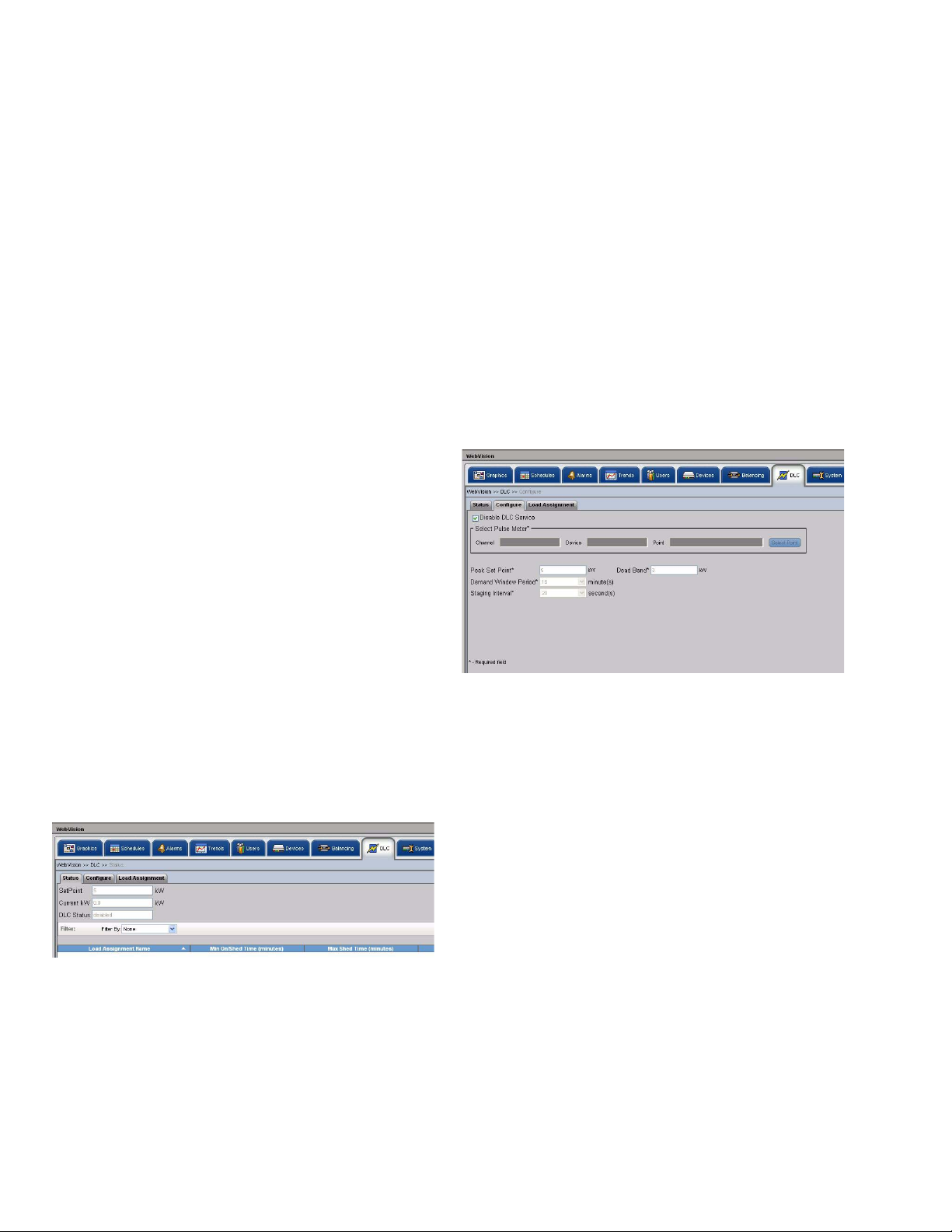
WEBVISION™
Load Shedding Method
1. The DLC starts shedding by first searching for all the Off
Continuous loads that are eligible for shedding.
2. Then, it first sheds the lowest numbered Off Continuous
load and waits the staging interval to see if the demand
has reduced.
3. If the demand is still above the peak setpoint, then DLC
sheds another Off Continuous load. This process
continues until the demand is well within the peak
setpoint limits.
4. If the demand has still not reduced, then DLC searches
for all the Rotated loads.
Load Restoring Method
• If the demand drops below the normal level, then the loads
that are currently shed will be actively restored one at a
time, every staging interval, until the demand reaches the
normal level. When restoring loads, DLC, on priority,
searches and restores:
• The Rotating loads where the load that has been shed
for the longest period is restored first.
• Then the Off Continuous loads where the load
restoration goes from highest load number to the
lowest load number.
• Loads are restored every staging interval if the override
condition becomes true or the maximum shed time has
been met. All loads that satisfy these conditions are
restored.
Use one of the following filter options to search for the
required load assignment:
• Load Name Pattern
• Shed Method
• Shed State
NOTE: To quickly search, type the first letter of the required
filter criteria in the Keyword text box and type an
asterisk (*). This lists all the names starting with the
first letter that you have written in the Keyword text
box.
3. The following information is displayed:
• Load Assignment Name
• Min On/Shed Time
• Max Shed Time
• Shed Status
To configure the DLC:
1. Click the DLC tab. The DLC Status page appears.
2. Click the Configure tab. The Configure page appears.
DLC Status
Demand Limit Control is a function that controls the maximum
power demand made on the whole system by shedding some
of the load based on priority where total power usage of
configured loads exceeds the predefined limit. Shedding
requires turning off some digital output, or changing a setpoint
to a more economical level.
You can view the DLC service status that includes all load
assignment details. DLC status is updated at the rate of the
staging interval.
To view the status of the DLC:
1. Click the DLC tab. The DLC Status page appears.
Fig. 27. DLC Status page.
2. The following information is displayed as read only text:
• Setpoint: Displays the setpoint value.
• Current KW: Displays the average power
consumption of the total assigned load.
• DLC Status: Displays the current DLC status. Four
modes present are: Disable, Deadband, Shed, and
Restore.
NOTE: Use Filters to quickly search the required DLC mode.
Fig. 28. DLC Configure page.
3. Select the pulse meter options. Click Select Point. A
Selected Pulse Meter pop up appears. Select a
Channel, Device, and Point for configuring DLC and
click OK.
NOTE: Check the Disable DLC Service check box to
disable the DLC service.
4. Enter/Select the following parameters:
• Peak Set Point: Enter the setpoint to set as the
peak limit. The range for peak set point value is 0-
6000.
• Demand Window Period: Select the demand
window period from the Demand Window Period
drop-down list. The valid range is in steps of 1
minute to 15 minutes. It is the time interval over
which the instantaneous KW demand is averaged to
determine the effective KW peak demand value.
This value, in turn drives the DLC to shed or restore
loads. The demand value is read from the pulse
meter for every 15 seconds and the average
demand value is calculated accordingly.
• Staging Interval: Select the staging interval from
the Staging Interval drop-down list. The valid range
is in steps of 20 seconds to 120 seconds.
WebVision collects the KW samples for every 15
95-7769—01 22
Page 23
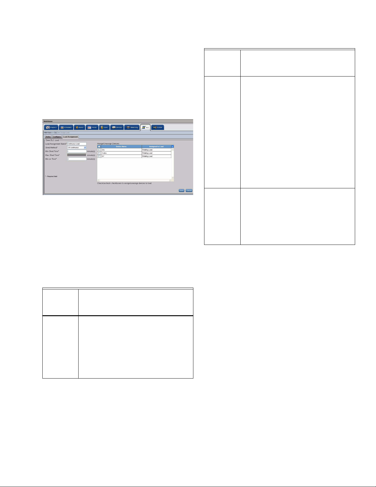
WEBVISION™
seconds and at the end of a staging interval,
compares the power consumption with that of the
active demand setpoint and the dead band.
• Dead Band: Enter the dead band in the Dead Band
text box. The dead band peak value is 1000.
5. Click Save to save the settings.
To add a Load:
1. Click the DLC tab. The DLC Status page appears.
2. Click the Load Assignment tab. The Load
Assignment page appears.
Fig. 29. Load Assignment page.
3. Click Add Load. The Add Load page appears.
4. Enter/Select the following details:
NOTE: All the fields marked with and asterisk (*) are
mandatory.
• Load Assignment Name: Enter a unique name for
load assignment.
• Shed Method: Select a load shed method from the
Load Shed Method drop-down list.
Table 4. Load Shed Methods.
If you have
selected the
Load Shed
Method as… Then…
OFF
Continuous
Load
In the Minimum Shed Time box, enter the
minimum length of time a load must be off
after it is shed by the DLC. In the Minimum On
Time box, enter the minimum length of time
the load must be active before it can be shed
or restored by the DLC.
NOTE: The valid range for the minimum
shed time and minimum on time is 0
to 99 minutes.
Table 4. (Continued)Load Shed Methods.
If you have
selected the
Load Shed
Method as… Then…
Rotating
Load
Last
Resort
Load
• Min Shed Time: Enter a valid value within the
• Max Shed Time: Enter a valid value within the
• Min On Time: Enter a valid value within the
• Assign/Unassign Devices: After configuring a
5. Click Save to save the settings.
In the Minimum Shed Time box, enter the
minimum length of time a load must be off
after it is shed by the DLC. In the Maximum
Shed Time box, enter the maximum time a
load that is shed by the DLC, must remain off
or inactive.
NOTE: The maximum shed time must
always be greater than the minimum
shed time. A load cannot be in the
shed state for more than the
configured maximum shed time. It
can be restored after the minimum
shed time has elapsed (lesser than
the setpoint minus the dead band).
In the Minimum On Time box, enter
the minimum time that the load must
be active ('On').
In the Minimum Shed Time box, enter the
minimum length of time a load must be off
after it is shed by the DLC.
NOTE: The maximum shed time for a Last
Resort load is twice its minimum
shed time and is displayed as
disabled text in the Maximum Shed
Time box.
specified 0-99 minutes range.
specified 0-99 minutes range.
specified 0-99 minutes range.
load, you can assign it to an external load object,
which in turn controls the electrical loads. All the
devices with the Device Name and their Assigned
Load (the name of the load that is assigned to that
device) are listed. Check the devices that you want
to assign to the current load.
To edit the Load:
1. Click the DLC tab. The DLC Status page appears.
2. Click the Load Assignment tab to display the Load
Assignment page.
3. Select the load to edit from the Load Assignment
Name list and the selected load's details appear.
4. Modify the required fields as described in step 4 of “To
add a Load:” on page 23.
5. Click Save to save the settings.
Assign Load
It displays the status of an individual load assignment or all
load assignments. If the DLC load configuration is modified,
then the load assignment status is displayed as Normal.
WebVision restores all the load assignments immediately by
23 95-7769—01
Page 24
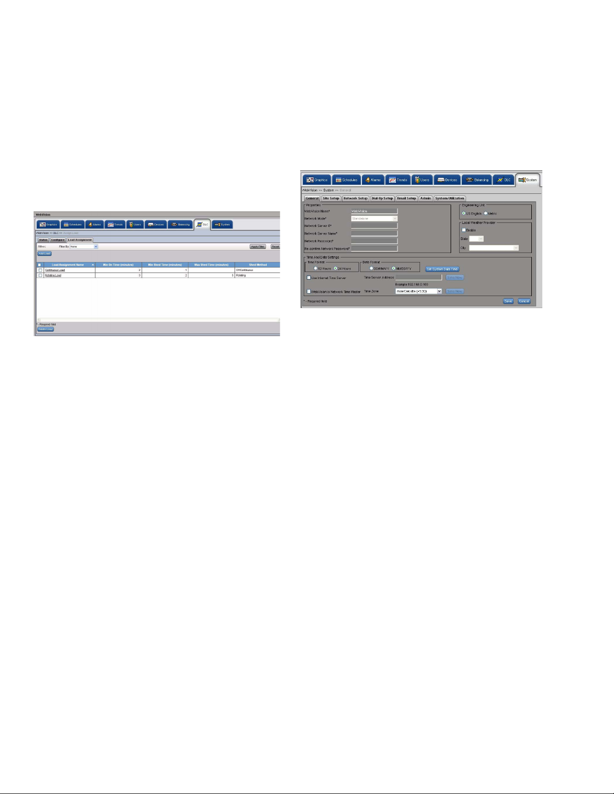
WEBVISION™
issuing a restore command even if the load assignments are
in the shed state. After re-loading the configuration, all the
Minimum On/Shed timers are also reset.
NOTE: When DLC is in the Reloading Configuration
mode, only the status of the load assignments is
displayed. It implies that the respective load objects
are not displayed.
To view the load assignment details:
1. Click the DLC tab. The DLC Status page appears.
2. Click the Load Assignment tab. The Load
Assignment page appears.
Fig. 30. Load Assignment Details.
3. The following information appears in a tabular format:
• Load Assignment Name: A unique name for load
assignment.
• Min On Time: Displays the minimum period for
which the load is active.
• Min Shed Time: Displays the period for which the
load is shed.
• Max Shed Time: Displays the maximum period for
which the load is shed or made inactive.
• Shed Method: Displays the method used to shed
load. For example, it can be Rotating, Off
Continuous, and so on.
Delete Load
To delete a load
1. On the Load Assignment page, select the name of the
load you want to delete from the Load Assignment
Name column.
2. Click Delete. A confirmation message appears.
3. Click OK to confirm the deletion.
System
You can use the System page only if you have a Contractor's
privileges. Use this page to configure general settings of the
system that include Time and Date settings, new package
installation, SMTP settings, Network settings, and Home Page
settings.
Use this System page to configure:
• General Properties
•Site Setup
• Network Setup Details
• Dial In Settings
• E-mail Setup
•Admin
• System Utilization
To configure the System general properties:
Use the following procedure to configure the system general
properties:
1. Click the Systems tab. The General tab of the System
page appears (Fig. 31).
Fig. 31. System Tab - General Tab.
2. Enter/Select the following site details:
• Properties
• WebVision Name: The entered WebVision
name is displayed.
• Time and Date Settings
• Select the Time Format and Date Format.
• Click Set System Date Time. The Set System
Date Time box appears. Set the date and time
and click OK.
•Select Use Internet Time Server to enable this
option. The Time Server Address is enabled. Set
the host name of the Internet Time Server.
Ensure that the DNS server that WebVision uses
(DNS configuration done in Network Server) for
hostname to IP resolution must be able to
resolve the host name of the Internet. Time
Server to IP address. Ensure that WebVision is
connected to Internet and is able to access the
time server. If you are not sure how to do it,
contact your local Network Administrator for help.
NOTE: WebVision automatically synchronizes its time with
the internet time servers. Synchronization happens
every 24 Hours or when the Sync Now button is
pressed.
• WebVision is Network Time Master: Select this
box to enable periodic time synchronization
between WebVision and devices on the network.
Time synchronization happens every 24 Hours,
when the system clock is changed, DST starts or
ends or when the Sync Now button is pressed.
• Time Zone: Select the applicable time zone of
the WebVision (where the WebVision is
installed). Every time the Time Zone is changed,
you must reboot WebVision to apply the new
time zone. Click Save after selecting the new
time zone, WebVision prompts you to reboot the
machine. After reboot, set the time and date as
explained above.
95-7769—01 24
Page 25

WEBVISION™
3. Choose US English or Metric as the standard for
setting the Engineering Units. All the point values in
the WebVision user interface are shown in the selected
unit.
4. For local weather, check the Enable check box. Select
a State and City from the corresponding lists.
5. Click Save to save the settings.
To configure Site setup:
Use the following procedure to configure the site setup:
1. Click the Systems tab. The System page with General
Properties appears.
2. Click the Site Setup tab. The Site Setup page appears.
3. Enter the following site details.
NOTE: Note: The supported background image formats
include: jpg, jpeg, and gif. The size of the image file
must not exceed 1MB.
• Contractor Details:
•Company Name
•Contractor Phone
• Contractor Website
• Contractor Email
• Company Logo: Click the Browse button to
browse for the site logo. Upload the selected
logo.
• Login Screen Image
• Image: Click the Browse button to browse for
the site image. Upload the selected image.
NOTE: Click Reset Image to restore the default image.
4. For outside air temperature, click Select Point and
select Channel, Device, and Point from the
corresponding list.
NOTE: Click Clear to clear the fields.
5. To provide weather conditions from an external link,
type the required URL and a Display Name for the link.
6. Click Save to save the settings.
To configure Network setup:
Use the following procedure to configure the network setup:
1. Click the Systems tab. The System page with General
Properties appears.
2. Click Network Setup. The Network Setup page
appears.
3. Enter/select the following details:
• IP Settings:
• Host Name: Host Name is the name of the
WebVision on TCP/IP network. This name is
used to find WebVision on the network with the
help of the DNS server.
• Domain: Name of the domain in which
WebVision exists.
• DHCP: To assign IP addresses dynamically.
NOTE: Since the IP address changes frequently, it is not
possible to communicate with other WebVision
applications on the network.
• IP Settings: (continued)
• IP Address: A 32 bit address used to identify
WebVision on IP network. This address is
typically represented in dotted-decimal notation,
with the decimal value of each octet separated
by a period, for example, 192.168.0.1.
• HTTP Port: Enter the port number. The default
port number is 80. If the port number entered is
other than 80 then you must type the
application's URL followed by the port number.
For example, http://199.63.24.224:81.
• Network Mask: This is used to separate Network
Address and Host Address from IP Address in an
IP network. For example:
IP address - 192.168.1.100
Network Mask - 255.255.255.0
(IP Address) & (Network Mask) = Network
Address = 192.168.1.0
(IP Address) & (Network Mask)' = Host Address
= 0.0.0.100; where “&” is logic and operation and
“'” is the logic complement operation.
• Gateway IP Address: IP Address of a host that
is used as a gateway by WebVision to
communicate with hosts on other networks.
Typical scenario is when you connect to
WebVision using a host on a different network
using a browser.
• DNS1 Server Name: The IP Address of the host
on the network that WebVision uses to resolve
host name to IP Address or vice-versa. This
service is mainly utilized by WebVision for Mail
Notification and Internet Time Synchronization.
• DNS2 Server Name: The IP Address of the host
on the network that WebVision uses to resolve
host name to IP Address or vice-versa. This
service is mainly utilized by WebVision for Mail
Notification and Internet Time Synchronization.
• Mac ID: The unique hardware identification of a
network device.
• Map Host Name to IP Address:
• Click Advance Settings. The Advance
Settings window appears.
•Type the Host Name. It is a unique name
given to a network equipment. You can
change it if required. The host name
corresponds to the MAC address.
•Type the IP Address. It is the numerical
address used to identify a device on a
network.
• Click OK. Each host Name is mapped to the
specified IP Address. You can use either to
access the device on the network.
• Channel Info:
• Channel Name: LonNetwork name used in the
WebVision.
• Domain ID: This is used to name a group of
devices connected to a LonNetwork. The
Domain ID must contain numbers form zero [0] to
nine [9] and must be in pairs. For example, if the
length of the Domain ID is configured as 3, then
the Domain ID is 12 34 56. There must be a
space between each pair.
• Subnet/Node ID: The Subnet represents a
LonNetwork and Node ID represents a controller
on that network. Here this Subnet/Node ID is
used to identify the LonNetwork of the
WebVision.
25 95-7769—01
Page 26
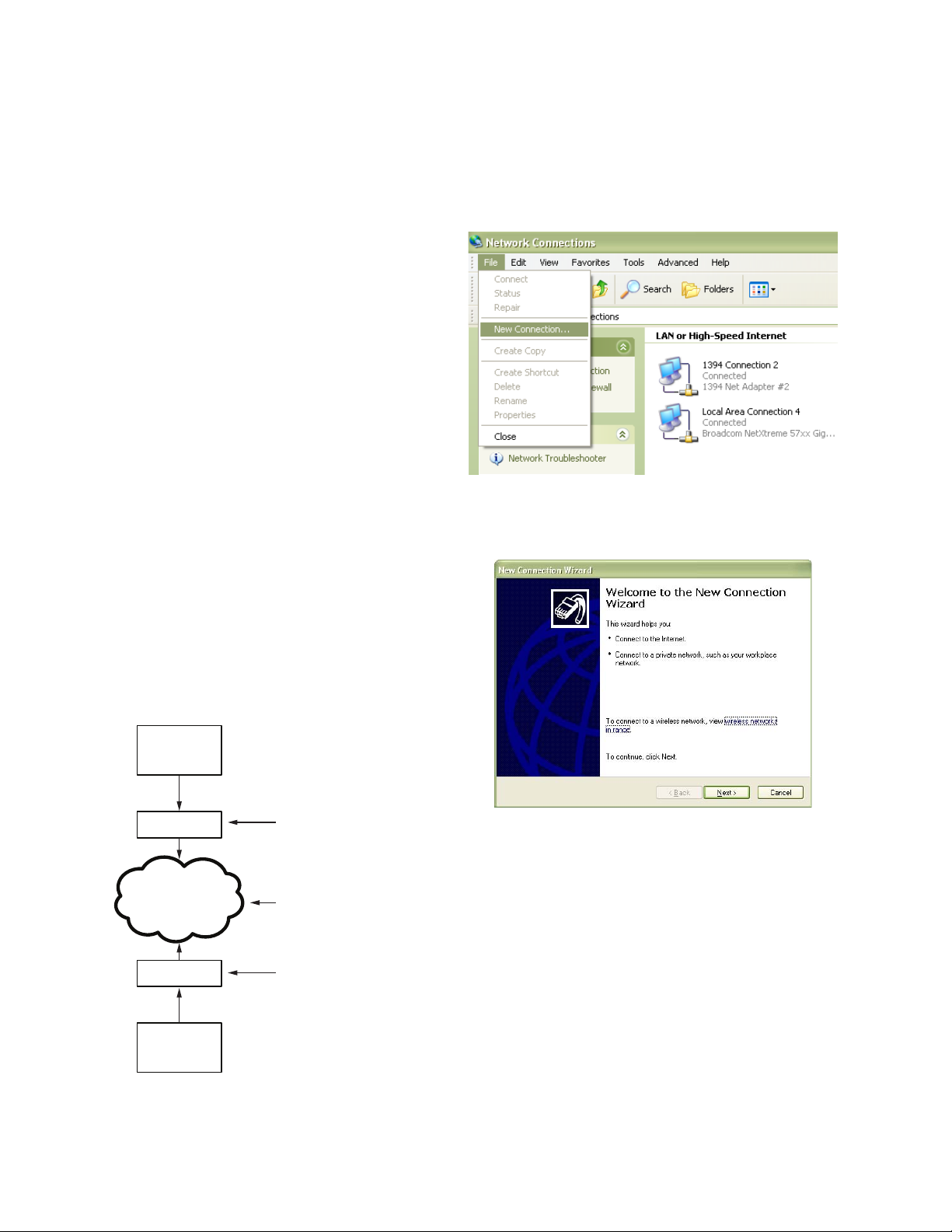
WEBVISION™
• Channel Info: (continued)
• Domain Length: Length of the Domain ID.
4. Click Save to save the settings.
To configure Dial-up settings:
Use the following procedure to configure the dial-up settings:
1. Click the Systems tab. The System page with General
Properties appears.
2. Click the Dial-Up Setup tab. The Dial-Up Setting page
appears.
3. Select required option from the Dial Up Type group
box. Whenever you are not on network and still want to
access WebVision, you can use the Dial-in facility.
Using this feature you can access WebVision from
anywhere.
4. Enter the following details.
• Dial In:
• Local IP Address: IP address of the local
machine from where you want to access the
WebVision application.
• Remote IP Address: IP address of remote
machine where WebVision application is hosted.
• User Name: Type the user name.
• Password: Type the password.
• Modem Setting:
• Initialization String: As specified in the
specification of the modem used.
• Baud Rate: As specified in the specification of
the modem used.
To enable Dial In settings:
Complete the following procedure to enable the dial in settings
on your computer/laptop:
1. Go to Start > Settings > Control Panel > Network
Connection.
2. Go to File > New Connection.
Fig. 33. File - New Connection menu selection.
3. The New Wizard screen appears. Click Next.
NOTE: The default modem settings works for most of the
modems. If the modem is not working, then change
the configuration.
5. Click Save to save the settings.
Deployment Diagram
WEBVISION
MODEM
PSTN
MODEM
PC / LAPTOP
DAIL-UP ADAPTER
LOCAL IP ADDRESS
USERNAME
PASSWORD
DAIL-UP ADAPTER
REMOTE IP ADDRESS
M28781
Fig. 34. New Connection Wizard screen.
Fig. 32. Deployment Diagram.
95-7769—01 26
Page 27
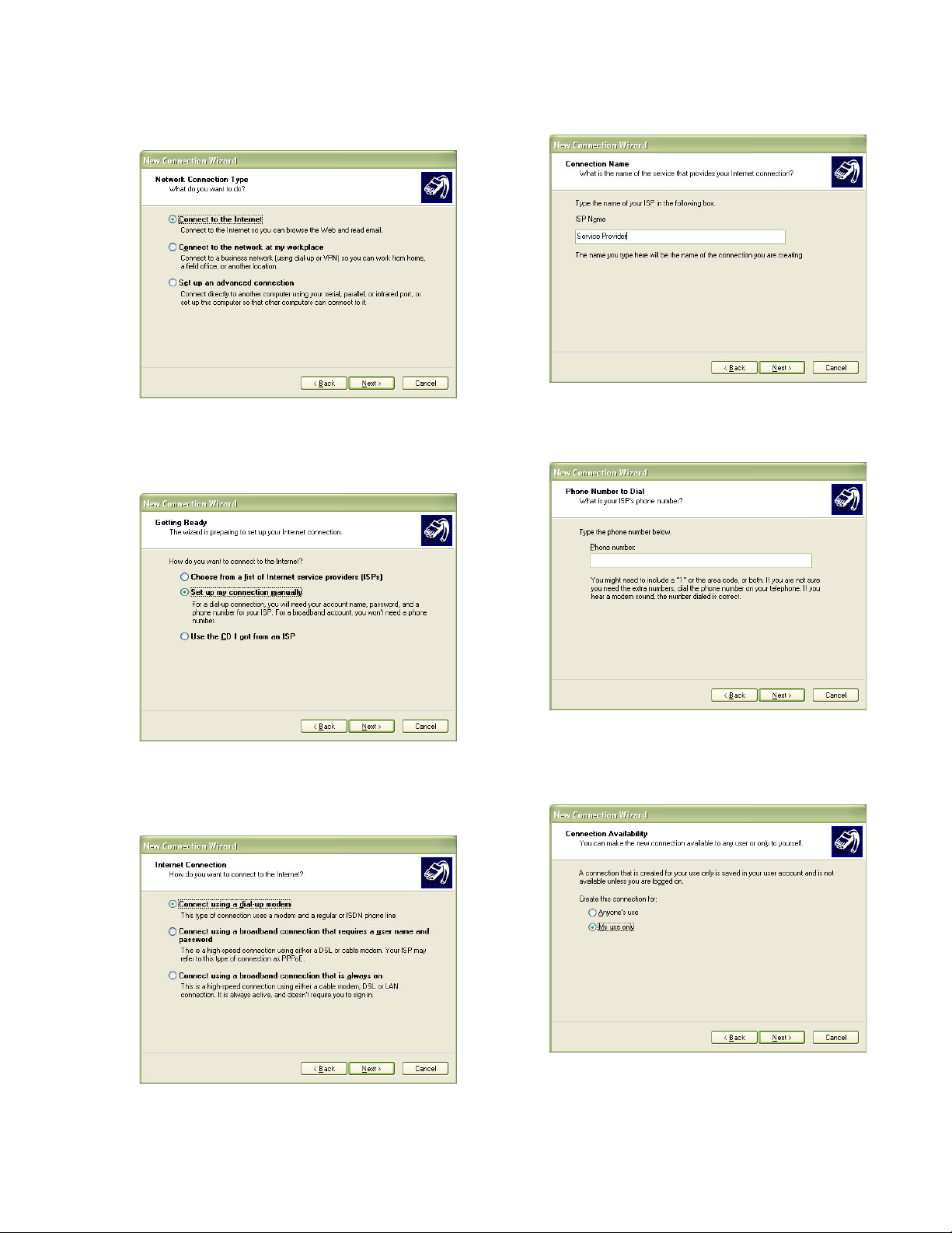
WEBVISION™
4. Select the Connect to the Internet option and click
Next.
Fig. 35. Network Connection Type screen.
5. Select the Set up my connection manually option and
click Next.
7. Type the name of the service provider and click Next.
Fig. 38. Connection Name - Service Provider.
8. Type your phone number and click Next.
Fig. 39. Phone Number to Dial screen.
Fig. 36. Setup my connection manually - button
6. Select the Connect using a dial-up modem option and
click Next.
Fig. 37. Connect using a dial-up modem button.
27 95-7769—01
9. Select the required option for connection availability and
click Next.
Fig. 40. Connection Availability screen.
Page 28
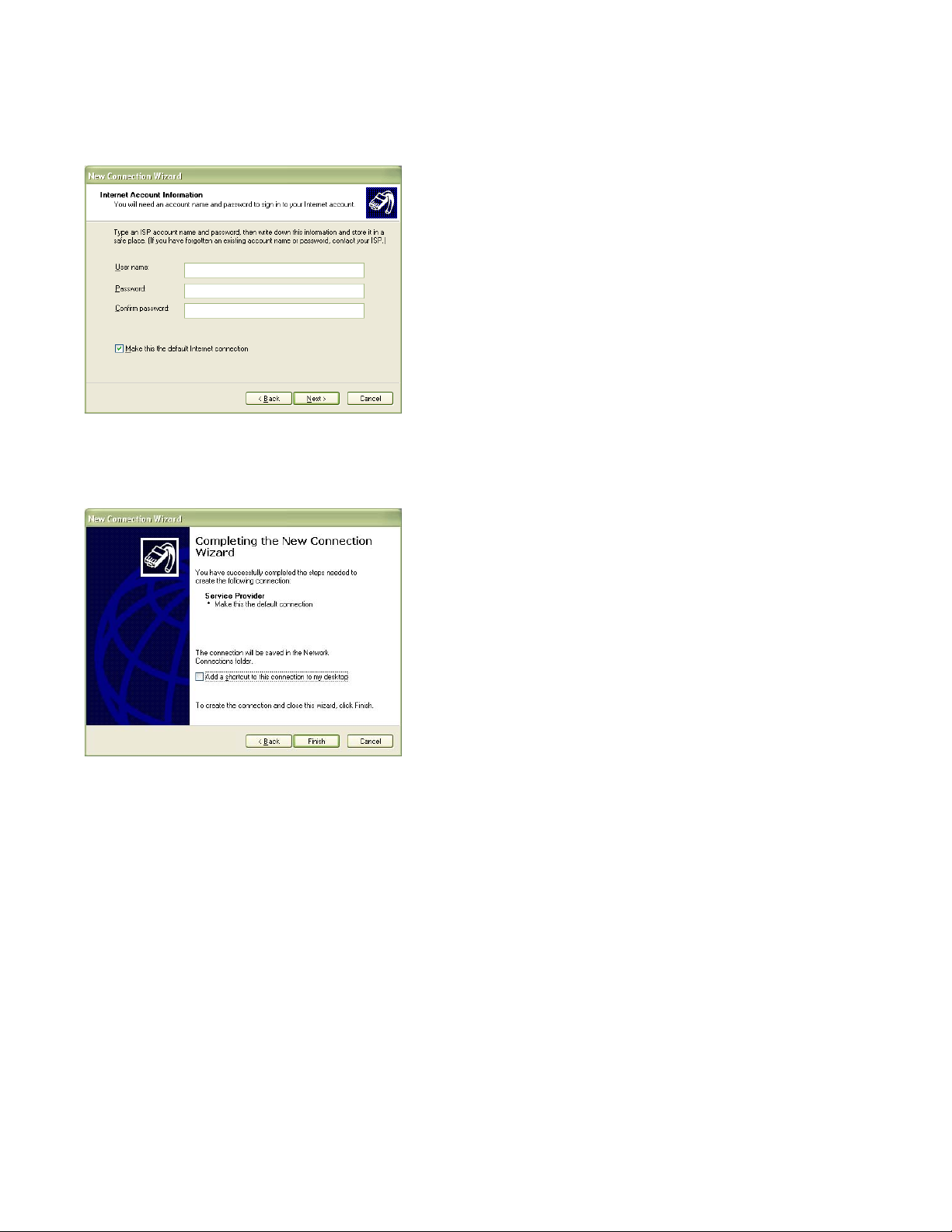
WEBVISION™
10. Type the user name and password and click Next.
The same credentials are used while enabling dial in
settings in WebVision.
Fig. 41. Internet Account Information - User Name and
Password.
11. Click Finish to complete the connection.
server and domain names prior to configuring the
SMTP E-mail server option. An example to
maintain the format: SMTP.server.com.
• Email Address: Enter a valid e-mail address.
The account must be present in the SMTP
server.
• User Authentication: Check this box to provide
the user credentials. On selection it enables the
following parameters.
• User Name: Type the user name of the SMTP
server. Type any name of your choice. For
example, webvision1.
• Password: Type the SMTP password.
• Confirm Password: Retype your password.
NOTE: The password field cannot be empty. The maximum
number of characters is 50. The characters allowed
are: a-z, A-Z, 0-9, _, !, @, #, $, %, ^, *, -, |, SPACE.
4. Click Save to save the settings.
5. Click Send Test Mail. The Email Service Status
displays the status. A test message is sent to the e-mail
address. A confirmation message appears.
6. If the settings are incorrect then, the Last Failure
Message field displays the reason for failing in sending
the message.
Configuring Admin
These files have .dist as the file extension. You can upload
files up to 5MB in size.
Complete the following procedure to install a new package:
1. Click Browse to upload the Software Update Package.
This allows you to install software updates, if any, that
are published by Honeywell for WebVision.
2. Click Install.
Reboot WebVision
1. Click the Reboot button to reboot WebVision. This logs
you out and then initiates reboot.
2. Re-logon after 5 to 10 minutes after the reboot is
Fig. 42. Completing the New Connection Wizard screen.
To configure E-mail setup:
Complete the following procedure to configure the e-mail
setup details:
1. Click the Systems tab. The System page with General
Properties appears.
2. Click the Email Setup tab. The Email Setup page
appears.
3. Enter the following details:
• SMTP Server
• Enable Email Service: Check this box to enable
the SMTP protocol.
• Use Sever WebVision as SMTP gateway:
Check this box to use WebVision server as
SMTP gateway.
• Email Server: Enter the SMTP e-mail server to
use this service.
You must configure SMTP e-mail server to send
alarm notifications. The Internet Service Provider
(ISP) or Network Administrator has to provide the
completed.
Backup Configuration
The backup file has .dist as the file extension.
Complete the following procedure to backup the configuration
settings:
1. Click Backup Configuration to backup the
configuration settings.
2. A window appears prompting you to Save the backup
file.
3. Click Save to save the backup file and specify the
location for the file.
or
Click Cancel to close the pop-up.
Restore Configuration
You can restore the backed up files using this feature. The
backup file has .dist as the file extension.
Complete the following procedure to restore the configuration
settings:
95-7769—01 28
Page 29

WEBVISION™
1. Click Restore Configuration to restore the
configuration settings from the backup file. The Restore
Configuration dialog box appears. Select the backup
file that has to be restored.
2. Click Restore. WebVision restores the file and
automatically logs out before starting to restore. Once
restoring is complete, WebVision automatically reboots.
This may take about 5 to 10 minutes.
3. Logon to WebVision again, after 5 to 10 minutes.
NOTE: When saving the file, the default File Type option is
.dist.
Download Audit Log
Complete the following procedure to download the audit log:
1. Click the Download Audit Log button.
2. Click Open to view the file.
or
Click Save to save the file at the required location.
The file displays information related to the action performed
by all the users.
Download System Log
Complete the following procedure to download the system
log:
1. Click the Download System Log button.
2. Click Open to view the file.
or
Click Save to save the file at the required location.
The file displays the logged system level error and trace
message.
System Utilization
Complete the following procedure to view system
performance:
1. Click the Systems tab. The System page with General
Properties appears.
2. Click System Utilization. The System Utilization page
appears.
3. You can view the Resource Utilization graph details on
your screen.
NOTE: This screen helps you to understand the WebVision
resources that are being used.
Migration of LCBS Sites in WebVision
Ensure that the site configuration backup is available in
LonSpec.
You should use either LonSpec or WebVision as the primary
configuration tool. Having more than one tool would require
effort to keep them in sync that is manual and error prone.
At certain sites where XL15B is installed, the most current
LonSpec database is present on the XL15B. Such databases
must be brought into LonSpec and used for migration.
Device Configuration Changes
Device configuration covers seven areas:
1. ”Decommissioning XL15A”
2. “Decommissioning XL15B” on page 30
3. “Decommissioning T7300” on page 30
4. “T7350 Changes” on page 30
5. “XL15C changes” on page 30
6. “LONSpec Changes” on page 32)
7. “WebVision Configuration Steps” on page 32
Decommissioning XL15A
Following are the considerations for de-commissioning XL15A
(W7760A):
1. Alarms – Alarms in XL15A cannot be automatically
transferred to WebVision. Looking at the XL15A
configuration in LonSpec, manually create
corresponding Alarms configuration in WebVision.
Follow the steps given in User Guide or Online help to
understand how to create Alarms in WebVision.
2. Trends – Trends in XL15A cannot be automatically
transferred to WebVision. Looking at the XL15A
configuration in LonSpec, manually create
corresponding Trends configuration in WebVision.
Follow the steps given in User Guide or Online help to
understand how to create Trends in WebVision.
WebVision comes loaded with default trends for each
type of supported device in disabled state. If the trend
that has to be created is already present and meets the
requirement, the user is advised to just enable that
trend instead of creating a new one.
3. Schedules – Looking at the XL15A configuration in
LonSpec, manually create corresponding Schedules
configuration in WebVision. Follow the steps given in
User Guide or Online help to understand how to create
Schedules in WebVision.
4. Loops – WebVision does not support inbuilt loops.
However, if this feature is critical, the user can replace
XL15A with XL15C. Or the user can disconnect XL15A
from the Lon Network. If XL15C is used, the same loops
can be configured in XL15C using LonSpec and recommissioned. If the XL15A is disconnected from
network, the user should be aware that it may be driving
RIOs or may have bindings with other devices to get
some sensor information. The device should be
reconfigured and re-commissioned using LonSpec to
remove such dependencies.
5. Network Time Master – If XL15A is acting as Network
Time Master, when decommissioned, WebVision can be
configured to act as Network Time Master. Refer
WebVision’s User Guide or Online Help for details.
6. DLC – If XL15A is performing Demand Limit Control
(DLC). The same can be done in WebVision. However
the user should note that WebVision supports only one
Setpoint. The configuration has to be done as
appropriate. Refer WebVision’s User Guide or Online
Help for details.
7. Pulse Meter Input – If a Energy Pulse Meter is
connected to XL15A because it is running DLC or
because it is providing that information to a different
XL15A, then if replacing XL15A with XL15C will allow
the user to configure XL15C to connect Pulse Meter and
act as source for KW input for DLC running in
WebVision.
29 95-7769—01
Page 30

WEBVISION™
8. Alarm Dial-Out – This feature is not supported by
WebVision or by any alternate mechanisms. Hence this
has to be dropped as part of migration process.
9. Runtime Logs - This feature is not supported by
WebVision or by any alternate mechanisms. Hence this
has to be dropped as part of migration process.
10. Bindings between XL15A and RIOs – XL15A can be
replaced with XL15C to drive the loops configured. If the
loops are driving RIOs, the same be achieved using
XL15Cs and RIOs. The user should replace XL15A with
XL15C, configure the same loops in XL15C, associate
RIOs to XL15C in LonSpec and re-commission XL15C
and RIOs.
NOTE: The user should remember that replacing a controller
would involve rewiring and testing the physical
installation. The new XL15C that is replacing existing
XL15A has to be purchased separately and will not
be provided along with WebVision.
Decommissioning XL15B
WebVision supports most of the functionality of XL15B.
However XL15B configuration has to be manually created in
WebVision. Configuration of the following functions should be
recreated in WebVision:
1. Alarms
2. Trends
3. Schedules – Unlike in XL15B, WebVision does not
support year round schedules. WebVision supports
weekly schedules that repeat through out the year.
Hence the schedules should be modified accordingly
4. DLC – Note that WebVision supported only one
Setpoint as against three in XL15B. Configuration
should be done accordingly
5. Special Graphics – Special Graphics in XL15B can be
created as Locations and Graphics on Locations in
WebVision
6. Network Time Master functionality
7. Internet Time Synchronization
8. Alarm Emailing
9. User accounts
10. Home Page graphics and Login Page graphics
Decommissioning T7300
Following are the considerations for de-commissioning
T7300:
1. If the devices on the Lon network are following schedule
in T7300, then a similar schedule should be created in
WebVision and assign those devices to follow schedule
created in WebVision. The schedule configuration can
be referred in LonSpec and has to be manually created
in WebVision.
2. If T7300 is acting as Network Time Master, the Network
Time Master Functionality in WebVision has to be
enabled. Once enabled, WebVision will synchronize the
clocks on all supported devices with Real-Time Clocks
that can be updated over the Lon network
T7350 Changes
WebVision supports configuration and management of T7350:
1. If a T7350 exists at the site and is driving scheduled
occupancy state of other devices, the user should
ensure that none of the schedules in WebVision drive
the occupancy state of those controllers that are
following T7350. If WebVision has to drive the
occupancy state of those controllers, user should first
unassign them from T7350 in LonSpec, commission
T7350 and the assigned controllers before configuring
schedules in WebVision
2. If T7350 is acting as Network Time Master, it has to be
disabled from LONSpec and re-commission T7350. The
Network Time Master Functionality in WebVision has to
be enabled. Once enabled, WebVision will synchronize
the clocks on all supported devices with Real-Time
Clocks that can be updated over the Lon network
XL15C changes
XL15C is supported in WebVision. However, there are some
differences that should be noted (below):
1. LonSpec creates bindings between XL15Cs and
assigned RIOs as shown in ‘refer points’ screen. These
bindings are present to read/command all I/Os on RIO
even if they are not used. WebVision does not have
concept of associating RIOs with XL15Cs. Therefore,
following is the behavior during migration:
a. When the XL15C bindings are uploaded in WebVi-
sion, only used/ configured bindings are actually
shown and bindings on un-configured I/Os are
ignored
b. LonSpec allows naming I/Os of RIO (W7761).
These names are stored in associated XL15C’s secondary configuration file. As WebVision does not
support this file, all the RIO point names will appear
with default names in WebVision after migration.
User would manually associate them by creating
appropriate bindings between XL15Cs and RIOs.
2. If an XL15C controller at the site uses a poll point
configured to poll an unsupported LON device, the
Device, NV and Field information will not show up in
WebVision’s XL15C configuration wizard as the device
is not present in WebVision’s database. As part of decommissioning the unsupported device, the user has to
re-commission the XL15C so that information is
removed from the configuration
3. The time taken to upload/download XL15C depends on
the number of loops configured in that XL15C. If more
number of loops is configured, WebVision will take more
time to upload/download. XL15C stores each loop
configuration in separate sections in its memory.
WebVision while uploading reads general device
configuration, reads the number of loops, reads I/Os
configured and then uploads configuration of each loop
and I/O
4. WebVision will upload all the objects that are configured
and used in control logic. If there are any Math
Functions, Setpoints, Logic Loops, Start Stop Loops that
are just given names or engineering units but do not
read any input or drive any output, such objects may be
ignored. The same reason is applicable while
downloading from WebVision. This optimizes the
download/upload process and does not impact the
XL15C configuration.
5. While uploading bindings, WebVision will not upload
bindings in which unconfigured objects like Control
Loops, Start Stop Loops, Logic Loops, Analog Inputs
are acting as source or target of the bindings.
95-7769—01 30
Page 31

WEBVISION™
LONSPEC METRIC VALUES
LonSpec downloads metric values to the controller.
WebVision does not do any unit conversion of XL15C
configuration values when displaying in the user interface.
Therefore, what the user gets to see is what is present in the
controller. The following step eases the comparison process:
1. Before comparing XL15C configuration with LonSpec,
right click on the project and open Edit Project dialog as
shown in Fig. 43. Change the Engineering Units to
Metrics before proceeding further.
To fix the configuration error, use the following procedure:
1. Open the configuration of each XL15C and go to
Control Loops tab.
Fig. 44. LONSpec Configuration Screen.
2. Select Loop 6 (clDATLowLim) in control loops and click
Control Params. The Control Loop Parameters
dialog box appears.
Fig. 43. Edit project.
This ensures that you see all the values in LonSpec in the
Metric system.
FIXING RAPIDZONE CONFIGURATION ERRORS IN
LONSPEC
Due to a configuration error in RapidZone, sites built in
Rapidzone and migrated to LONSpec may have a
configuration error for every XL15C controller (W7760C). As a
result, device upload step in WebVision causes problems.
Fig. 45. Control Loop Parameters dialog box.
3. Select an appropriate option for Analog Limit Select
and click OK.
4. Repeat the above steps for all the XL15Cs.
5. After changing the Analog Limit Select, re-commission
all the XL15Cs with LONSpec.
31 95-7769—01
Page 32

WEBVISION™
LONSpec Changes
Complete the following steps for migrating the existing LCBS
sites to WebVision:
1. Ensure that LonSpec database which is used to
commission the site is ready. Open the LonSpec project.
Click Network > Edit on the menu bar. The Edit
Network dialog box appears.
Fig. 46. Edit Network dialog box.
2. Click Advanced Features. The Advanced Features
dialog box appears.
NOTE: When re-commissioning, please use full commission
command, not quick commission.
6. After re-commissioning, disconnect LonSpec from the
network.
WebVision Configuration Steps
Start the migration process on a fresh WebVision without any
existing config file. There should not be any devices present in
WebVision
1. Configure WebVision as given in the Quick Start Guide
and connect it to Ethernet and LON network.
2. Logon to WebVision through internet browser.
3. Click System > Network Setup. In Channel Info, set
the Domain ID to the same domain ID configured in
LonSpec typically 2C (44 decimal). The ID must be
specified in Hex format.Click Save to save the changes.
Fig. 48. Channel Info - Domain ID and Domain Length
fields.
4. Click the Devices tab and go to Device List screen.
5. Click Discover. A dialog box appears. Select Channel
as Channel 1 and click Discover. A progress bar
appears indicating the discovery progress.
6. After the discovery is complete, all the discovered
devices are listed on the left side of the table. Review
the subnet/node ids of discovered devices to ensure
that there are no conflicts. WebVision will detect the
clash and on confirmation from the user, it would
change the subnet/node id of the device.
Fig. 47. Advanced Features dialog box.
3. Set the Domain index for non-zero length domain to
0 (LNS based systems). Click OK to save the
changes.
4. Modify the original LonSpec project so that it does not
contain unsupported devices. The following are
frequently used:
a. XL15A
b. XL15B
c. Command Display 1 and 2
d. T7300
e. RapidLink/SLTA/PCLTA used by LonSpec, LonSta-
tion and XL15A.
f. RF Gateway
g. CX-VFD
It is highly recommended not to have these devices
physically connected to the Lon Network as it could
result in partial upload of binding information into WebVision, or worse interfere with WebVision functionality.
5. Disconnect WebVision from the network and recommission all the devices using LonSpec.
NOTE: Changing subnet/node id will break any bindings
going in and out of that device. It is suggested that
the user find the clash manually and rectify them
through LonSpec.
7. Select all the devices by clicking on each device (or
click the SelectAll box) and then click Add to add them
to WebVision database.
NOTE: The user should click on the device to select the
device in the discovered list to do further operation
on them. Although mouse scrolling across the
discovered devices records appear as selection,
they are actually not selected
8. Enter a name for each device that should appear in then
UI and click Done to complete the discovery process.
9. Select all the devices and click Upload to upload the
device configuration onto WebVision. A progress bar
appears indicating the progress of the Upload
operation. Once the upload is complete, the Synced On
option is enabled for each device.
10. Ensure that all the devices are in Auto mode in the
Mode Column. If any device is in Manual or any other
mode, select that device and click Set Mode to Auto.
11. Click the Device Bindings sub-tab next to Device List
subtab.
95-7769—01 32
Page 33

WEBVISION™
12. Click Upload to upload the LON binding information
onto WebVision. A progress bar appears indicating the
progress of the Upload operation.
NOTES
1. Ensure all the devices are in Auto mode. If you
see any device in Manual or any other mode,
select that device and click Set Mode to Auto to
change the mode.
2. Click Download in Devices > Device List or
Devices > Device Bindings to initiate the
process of writing configuration data that is
present in WebVision to devices. This operation
should be performed only if it is absolutely
necessary. If there is no requirement to change
the configuration in the devices this operation
must not be performed.
3. The migration procedure has been tested with
LonSpec version 05.01.00.00 and later. It is
recommended that users use at least this version
for migration.
4. After the auto-resolution of Node ID conflict, if the
configuration upload fails (especially for XL15C),
user should wait a minute and retry the operation.
5. WebVision does not support access through
PPPoE connection. PPPoE is the data link layer
protocol used for broadband internet connections.
If the user is using PPPoE, the user is advised to
purchase a WiFi router or equivalent that supports
PPPoE and connect WebVision to the Ethernet
side of the router. Follow the User Guide of the
router to have the desired setup
6. It is recommended that all the device
configurations and bindings are checked field by
field to ensure that the migration was successful
as expected. If any information is found missing,
the user can retry upload operation of
configuration/bindings as applicable. If that does
not solve the problem, user should manually fill in
the missing information. Any attempts to do
download without performing this operation may
break the control system in the site.
7. Points can be overridden through any means in
WebVision for a period of time. However, if
WebVision is powered off during that period and
re-started, WebVision will not restore the point i.e.
will not cancel the override even if the specified
override time has elapsed. In this case, a stale
value will be observed in WebVision. To cancel
the original override operation, the user should
override the point again for a minute and that
would restore the default value.
8. If XL15Cs use Math Functions that are type
Network Special, the configuration will get
uploaded properly into WebVision. However the
WebVision interface does not show Math
Functions of type Network Special in the user
interface.
WARRANTY AND RETURNS
Refer the user to Honeywell's standard warranty policy in the
Environmental and Combustion Controls Product Catalog
(form 70-6910). This literature is available on
customer.honeywell.com. Try the following link:
http://customer.honeywell.com/request.cfm?form=70-6910
33 95-7769—01
Page 34

WEBVISION™
APPENDIX A – SUPPORTED DEVICES
This appendix provides configuration information for the
following controllers and devices:
• W7763C/D/E Chilled Ceiling Controller (CHC) .... page 34
• Constant Volume Air Handling Unit Controller
(CVAHU) .............................................................. page 43
• Fan Coil Unit Controller (FCU) ............................page 54
• Hydronic Controller (HYD) ..................................page 64
• Excel 10 Remote Input/Output Device (RIO) ......page 73
• Vacon NX Frequency Converter (NXVFD) .......... page 89
• T7350 Thermostat (T7350) ................................. page 97
• Unit Ventilator (UV) .............................................page 74
• Excel 10 VAV II Controller (VAV II) ......................page 82
• XL15C Plant Controller (XL15C) .........................page 91
Configuring Chilled Ceiling Controllers (CHC)
Description
The W7763C, D and E Controllers are Chilled Ceiling
Controllers in the Excel 10 product line. They cover a wide
range of control applications including radiators, induction
units, and fan coil units with manual fan switching, chilled
ceiling and chilled beam and are suitable for either wall
mounting or unit mounting. The controllers can operate as
stand-alone units or networked using the standard Echelon
ONWORKS bus. Interfaces are provided for a wide range of
L
actuator types. Heating systems can be water or electric, and
cooling systems can be chilled water supply or compressors.
Extensive timing and interlock features make the W7763
especially suitable for systems using electric heat and
compressors.
Navigating to CHC Pages
Go to the Devices tab. Expand the list of devices on the left
pane (listed under WebVision). Select a device to view its
properties.
Features
• LonMark® HVAC profile 8020
• Stand-alone operation or on high speed 78 kilobit LON
network.
• Uses Echelon LonTalk protocol.
• Direct connection of thermal actuators.
• Factory-configured default parameters.
• Wide range of supported valves and actuators.
• Available with setpoint knob for wall mounting.
• Built-in LON jack for easy network access.
• LON service pin and LED accessible without disassembly.
The W7763C, D and E are LonMark-compliant Chilled Ceiling
Controllers in the Excel 10 family product line. These
controllers provide room temperature control using different
heating and cooling sequences. The controller is provided
with default configuration settings from the factory and is fully
operable on installation. Using standard Echelon configuration
tools, the controller can be configured with job-specific
settings. The TR21 and TR23 wall modules interface with the
Chilled Ceiling Controllers and provide the following options:
setpoint adjustment, an occupancy bypass button and LED,
®
®
and an LON jack. All wall modules include a space
temperature sensor, however a remote C7068A return air
sensor can also be used.
Supported Output Types
Table 5 lists the supported output types.
Table 5. Supported Output Types.
Output Options
Heating Floating, thermal, PWM, on/off, multi-stage
Cooling Floating, thermal, PWM, on/off, multi-stage
electric
compressor
Chilled Ceiling Controller Models
Table 6 lists the Chilled Ceiling Controller models.
Table 6. Chilled Ceiling Controller Models.
Setpoint
Model Inputs Outputs
W7763C 3 2 X X X
W7763D 4 2 X
W7763E 4 2
Knob Sensor Bypass
Sequences
Heat and cool sequences can be selected to be active or not
active, giving a total of four different sequence options:
• Heat only
• Cool only
• Heat/cool changeover
• Heat and cool sequence
The controller automatically disables heat and cool control
until the window is closed again. Frost protection remains
active.
Modes of Operation
The controller has the following modes of operation:
Occupied mode This is the normal operating condition for a
room or zone when it is occupied. The controller can be
switched into this mode by a network command, by the room
occupancy sensor, or by a bypass button on the wall module.
Standby mode The standby mode saves energy by reducing
heating or cooling demand during periods where the room is
temporarily unoccupied.
Unoccupied mode This mode is used for longer unoccupied
periods, such as at night or during weekends and holidays.
Window open If the controller is configured for window open
detection, the controller automatically disables heat and cool
control until the window is closed again. Frost protection
remains active.
Frost protection If the temperature drops below 46 °F
(8 °C), the controller enables the heating circuit as frost
protection.
95-7769—01 34
Page 35

WEBVISION™
Fan fail When configured with an air flow detector, the
controller protects equipment by disabling the system when
the fan fails (for fan coil units with manual fan speed control).
Changeover The controller operates two-pipe units
configured with a changeover input.
Dewpoint When configured with a chilled water temperature
sensor, the controller will close the cool valve when the chilled
water temperature falls below the dew point. The dew point
may be a fixed value or calculated based upon input from a
humidity sensor.
Condensation When configured with a condensation switch,
the controller will close the cool valve when condensation is
detected.
Input/Output
Table 7 lists the Input/Output (I/O) detail.
Table 7. Input/Output Detail.
PIN
I/O Function
Digital Window/
Digital
(See Table 5
on page 34)
Analog Humidity
Analog Temperature
Analog
(Wall
Module
Connection
Only)
occupancy/
changeover/
air flow/
condensation
Override 7 Closed ≤ 400 ohm
Sensor
Sensor
Setpoint
Adjustment
Number Characteristics
INPUTS
4 Closed ≤ 400 ohm
Open ≥ 10K ohm
Open ≥ 3.3k ohm
1 0 to 10 Vdc
3, 9 20K ohm NTC
(25 °C)
8 10k Ohm
Table 7. Input/Output Detail. (Continued)
PIN
I/O Function
Digital
(Wall
Module
Connection
Only)
Triac
(2 pairs)
Override
LED
Heat and
Cool
Number Characteristics
OUTPUTS
6 0 to 5 Vdc (≤ 10mA)
14, 15,
17, 18
24 Vac, 250 mA max
continuous,
650 mA max surge
(≤ 30 sec.)
CHC Outputs
Description
CHC applications can have a variable number of heating and
cooling stages. The number of pipes used on the unit could be
two or four. The outputs could be staged, PWM, floating, or
Thermal type. In addition the outputs can be of Change over
mode.
Purpose
Define the operation of the chilled ceiling controller outputs
and the type of equipment to be controlled.
Mode
Configuration can be performed with the wizard Off-line or
On-line.
Procedure
1. Click the Outputs button on the left pane to open the
Output Configuration page.
2. Enter information into available fields.
3. Click Commit to save the settings or Reset to revert to
the last saved settings.
4. Click Next to display the Input Configuration page.
CHC Output Fields
Table 8 describes the field definitions.
Table 8. CHC Outputs - Field Definitions.
Name Definition
Application
Safety
Select/disable ceiling protection
Condensation Protection
Chilled Ceiling protection option
It enables dew-point calculation and condensation protection. The cold water temperature value must be
available (either wired connected or shared via the network). If the humidity value is available (either connected
or shared via the network), the controller uses it to calculate the dew-point temperature for the cold water
temperature limitation; otherwise it uses a settable dew-point setpoint.
35 95-7769—01
Page 36

WEBVISION™
Table 8. CHC Outputs - Field Definitions. (Continued)
Name Definition
Application (continued)
No Condensation Protection
Disable the dew-point temperature calculation and protection. The cold water temperature and the humidity are
not needed by the controller; the chilled ceiling protection can still be performed by the condensation switch.
System
Define the type of equipment that is being controlled in terms of the number of pipes used on the unit.
Two Pipe
A unit that has only two pipes. Selecting this system type limits the controller to control only one valve output and
operate in a changeover mode. When operating in the changeover mode, the controller uses only the one valve
for controlling both heating and cooling. Use this configuration only when changeover operation is required.
Four Pipe
A unit that has four pipes connected, providing both heating and cooling at the same time. The controller uses
one output to control heating only and one output to control cooling only, as configured in the Outputs page.
Control Outputs
Configures the two control outputs for the different type of actuators and control sequences required for the
application.
Output 1 - Mode
The output triac pair connected to terminals 13/14/15 of the controller.
Select the control sequence option to be allocated to Output 1. For four-pipe applications, always allocate this
output to the heat option to minimize field wiring errors. For two-pipe applications, the changeover option is the
only option.
Heat Mode
The output is modulated open when heat energy is needed in the space.
Cool Mode
The output is modulated open when cool energy is needed in the space; it is also modulated to limit the cold
water temperature above dew-point temperature (if enabled).
ChangeOver Mode
The output is modulated open when heat or cool energy is needed in the space. In Cool Mode, the output is
modulated to limit the cold water temperature above the dew-point temperature (if enabled).
Not Used
The output is not controlled by the controller and is always off.
Output1 - Type
Select the type of actuator to be connected to the output.
Floating
A three-point actuator that can be commanded open or closed. It is on terminals 14/15 and/or 17/18. The runtimes for the actuator are configured in the Outputs page.
Floating
A three point actuator that can be commanded open or closed on terminals 14/15 and/or 17/18. The run-times for
the actuator are configured in the Outputs page. The Zero Energy Position (no Heat and no Cool) is the middle
Position (50%). The Cool Range is 0 to 50%; the Heat Range, 50 to 100%. The Range can be reversed by
selecting the Actuator Direct or Reverse Option. During the Synchronization Process, the fan is turned off.
PWM
A duty-cycled output where the 24VAC output is pulsed on/off in the duty cycle range 0% to 100%. This actuator
drives output terminal 14 and/or 17.
One Stage
A single-stage on/off output. It switches terminals 14 and/or 17.
Two Stage
A two-stage output: Terminals 14/17 are switched for stage 1 and terminals 15/18 are switched for stage 2.
95-7769—01 36
Page 37

Table 8. CHC Outputs - Field Definitions. (Continued)
Name Definition
Control Outputs (continued)
Three Stage
A three-stage switched output. Terminals 14/17 are switched for stage 1, terminals 15/18 are switched for stage
2. Both terminal 14+15 and/or 17+18 are switched for stage 3.
Thermal
A switched on/off output for switching a 24V thermal actuator on terminal 14/17.
Output 2 - Mode
The output triac pair connected to terminals 16/17/18 of the controller.
Select the control sequence option to be allocated to output 2. For four-pipe applications, always allocate this
output to the cool option to minimize field wiring errors. For two-pipe applications, only the changeover option is
available.
The selection options are the same as for Output 1.
WEBVISION™
CHC Inputs
Procedure
Purpose
To select the wall module parameters and input points to
configure a CHC controller.
Mode
Configuration can be performed with the wizard Off-line or
On-line.
CHC Input Fields
Table 9 describes the field definitions.
Table 9. CHC Inputs - Field Definitions.
Name Field and Definition
Controller / Wall Module
Configures the functionality of the connected wall module. Be careful that the features configured here are the same as the features
available on the wall module device to be connected.
Space Temp Sensor
Specify whether or not the controller is to be used with a space temperature sensor connected to its input. Normally, a space
temperature sensor is used, but in cases where the space temperature is supplied from another device via the network, the local
space temperature sensor input is not used.
Ye s
The local space temperature sensor input is used. Ensure that a space temperature sensor is actually connected otherwise the
controller measures incorrect values.
No
The local space temperature sensor is not used. This option must be selected when a sensor is not connected.
LED/LCD Display
This configuration defines whether a Wall Module with LED or a Wall Module with LCD Display is connected.
1. Click the Inputs button on the left pane to open the
Input Configuration page.
2. Enter information into available fields.
3. Click Commit to save the settings or Reset to revert to
the last saved settings.
4. Click Next to display the Equipment Control
Configuration page or Back to display the Output
Configuration page.
For the LED, either the Override Status or the Effective Occupancy Status is displayed. The LCD Display show the both - the
Effective and the Override Status and an additional Off Condition.
The Override Status results from the Scheduler, the Network Override, the Override Button and the Occupancy Sensor. The Off
Condition results from the Fan Speed Switch, the Window Contact and the Medium from nviApplicMode.
LED Override
The LED shows the Override from the Override Button or from the Network. On indicates Override Bypass, 1 Flash per Second
indicates Override Unoccupied, 2 Flashes per Second indicates Override Standby or Occupied. 4 Flashes indicates the Controller
answers of the Network Management Command Wink.
37 95-7769—01
Page 38

WEBVISION™
Table 9. CHC Inputs - Field Definitions. (Continued)
Name Field and Definition
Controller / Wall Module (continued)
LED Occupancy
The LED shows the effective Occupancy mode. On indicates effective Occupied or Bypass, 1 Flash per Second indicates effective
Standby, Off indicates effective Unoccupied. 4 Flashes indicates the Controller answers of the Network Management Command
Wink.
LCD Display
This mode is used only for a Wall Module with LCD Display. The Display has following Symbols to show the Occupancy Modes: Sun
indicates effective Occupied or Bypass, Half Sun indicates effective Standby, Moon indicates effective Unoccupied. No Symbol and
OFF in 7-Segment indicates the Controller is Off. In the Off mode, a Snow Flag indicates whether Frost Protection is configured.
Blinking Symbols are used to show the Override: Blinking Sun indicates Override Occupied or Bypass, blinking Half Sun indicates
Override Standby, Blinking Moon indicates override unoccupied. The Controller answers with the Network Management Command
Wink with blinking Sun and Moon.
Override Button
Define how the override button on the connected wall module is to be used.
None
The wall module button is not used for bypass function.
ByPass Only
The Bypass button, when pressed, has two different functions depending on the length of time the button is held down:
Two seconds puts the controller in Bypass.
Five seconds puts the controller in Unoccupied.
Bypass
The Bypass button, when pressed, has the following function:
In two seconds the controller is in Bypass mode.
Setpoint Knob
The setpoint knob is available in different types of scale, and with different setpoint meanings, based on the country of usage. The
temperature engineering unit used (°C or °F) is the setting made in WebVision when creating the new project. That setting is used
for the total project. Note that the setpoint knob only affects the Occupied and Standby Setpoints. The Unoccupied setpoint is not
affected by the setpoint knob. Note that Version C and D Chilled Ceiling controllers have an on-board setpoint. They cannot be used
with an external TR21 or TR23 setpoint device.
The range of setpoint knob value lies between -9tdf to +9tdf.
No Knob
The setpoint knob is ignored. Note that this must be chosen if there is no setpoint knob connected to the controller. This selection
prevents the controller from reacting to incorrect setpoint values.
Relative
The setpoint knob is a relative knob, showing only a setpoint shift as (+) and (-) changes to the configured setpoint.
Absolute Middle
The setpoint knob is an absolute knob, showing the setpoint in absolute degrees. It is used as the space temperature setpoint
midway between the heating and cooling zero energy band.
Setpoint Limits
These two fields specify the allowed range of adjustment available from the wall module setpoint knob. This range is used by the
building manager for energy management purposes, to balance allowed comfort conditions with energy usage.
(SETPOINT KNOB = RELATIVE)
When the setpoint knob has been chosen as relative, the setpoint limits define the range of adjustment of the setpoint knob from the
zero point, in (DDC) for °C installations and (DDF) for °F installations.
(SETPOINT KNOB = ABSOLUTE MIDDLE)
When the setpoint knob has been chosen as absolute, the setpoint limits are limits on the absolute range of the setpoint knob in
(Deg.C) for °C installations and (Deg.F) for °F installations.
95-7769—01 38
Page 39

WEBVISION™
Table 9. CHC Inputs - Field Definitions. (Continued)
Name Field and Definition
Input Ports
Specifies usage of the controller inputs
Analog Input 1 and Analog Input 2
a
Window Closed
Indicates if a window is closed. Close window disables the controller operation. If the contact is closed, the window is closed.
Window Open
Indicates if a window is opened. An open window enables the controller operation. If the contact is closed, the window is closed.
Occupied Sensor
Indicates if the room is occupied. If the contact is closed, the space is occupied.
Unoccupied Sensor
Indicates if the room is unoccupied. If it is unoccupied, the controller switches from the occupied operating setpoints to the standby
operating setpoints.
ChangeOver Cool
This selection is for local heat/cool changeover operation for two-pipe units using a switch or local thermostat switch. When the
contact closes, this input indicates that the system can operate in cooling mode. When the contact opens, this input indicates that
the system can operate in heating mode.
ChangeOver Heat
This selection is for local heat/cool changeover operation for two-pipe units using a switch or local thermostat switch. When the
contact closes, the input indicates that the system can operate in heating mode. When the contact opens, the input indicates that
the system can operate in cooling mode.
Condensation
Indicates if there is condensation in the ceiling. When condensation is detected, the controller closes the cooling output. The cooling
output is controlled again after 5 minutes if condensation is not detected anymore. When the contact closes, there is condensation.
No Condensation
Indicates if there is no condensation in the ceiling. As long as there is no condensation, the contact is closed. If the contact opens,
the controller closes the cooling output. The cooling output is controlled again after 5 minutes if condensation is no longer detected.
When the contact closes, there is no condensation.
Movement
This selection is used for movement detector configuration where a closed contact indicates movement. Movement detector is the
same as occupancy sensor, but with an additional Hold Time of 15 minutes. This adds a delay to the occupancy signal such that the
space is considered occupied until 15 minutes has elapsed since the last movement is detected.
Cold Water
The cold water temperature sensor input is used. Ensure that a cold water temperature sensor is actually connected otherwise the
controller measures incorrect values.
Not Used
The cold water temperature sensor is not used. This option must be selected when a sensor is not connected and is shared via the
network.
Analog Input 3
Specify whether or not the controller is to be used with a humidity sensor connected to its input. If the controller is configured for ceiling
protection, as defined in the Outputs page, the humidity must be either connected or shared via the network.
Humidity
The humidity sensor input is used. Ensure that a humidity sensor is actually connected; otherwise, the controller measures incorrect
values.
Not Used
The humidity sensor input is not used.
a
You cannot configure the same for Analog Input1 and Analog Input2. For example, you cannot configure Analog Input1 as
Window Contact and Analog Input2 as Window Contact. All digital inputs for Input2 are supported since controller version
1.0.4.
39 95-7769—01
Page 40

WEBVISION™
CHC Equipment Control
Purpose
Define the main control features of controller outputs.
Mode
Configuration can be performed with the wizard Off-line or
On-line.
Procedure
1. Click the Equipment Control button on the left pane to
open the Equipment Control Configuration page.
2. Enter information into available fields.
3. Click Commit to save the settings or Reset to revert to
the last saved settings.
4. Click Next to display the Switching Levels
Configuration page or Back to display the Inputs
Configuration page.
CHC Equipment Control Options
Table 10 describes the configuration options.
Table 10. CHC Equipment Control - Options.
Name Option and Definition
Output Options
Defines the operating characteristics of the two valve actuator outputs.
Output 1 and Output 2
Define operation of output 1 and output 2, as configured in the Outputs page. The settings for both Outputs have
the same meaning as described in the following text.
Valve Direction
Define the operating direction of the valves for actuator types Floating, PWM, and Thermal.
Direct
To open, the valve is modulated from 0% to 100%.
Reverse
To open, the valve is modulated from 100% to 0%.
Min Stage Off Time
Define the minimum off-time for control outputs configured for operation as staged outputs. This setting is
particularly useful for heat exchanger operation or compressor units. Each stage of the controlled output
stays off for the minimum period of time before the controller turns it on again. The selectable range is 0 to
600 seconds.
Valve Runtime
This configuration parameter has three different functions depending on the control output type selected in
Control Outputs.
(CONTROL OUTPUT TYPE = FLOATING)
The value is the actuator run-time in the range 20 to 600 seconds.
(CONTROL OUTPUT TYPE = PWM)
The value is the cycle period of the PWM output in the range 20 to 600 seconds.
(CONTROL OUTPUT TYPE = ONE, TWO OR THREE STAGE)
The value is the minimum on-time for each of the stages, for controlling compressor units
PWM Options
Configures the full range of the PWM outputs. For many PWM-controlled devices, an output of 0% or 100% is not
allowed since a PWM output shows no switching at these percentages. Therefore, most PWM devices have a
minimum duty cycle and a maximum duty cycle between which they operate from zero to full scale. The fields here
configure the full range settings. You can swap the Zero and Full range values to achieve reverse operation for a
PWM output.
Zero
PWM % duty cycle for fully closed position.
Full
PWM % duty cycle for fully open position.
95-7769—01 40
Page 41

WEBVISION™
CHC Switching Levels
Purpose
To configure the staged output switching levels.
Mode
Configuration can be performed with the wizard Off-line or
On-line.
Procedure
1. Click the Switching Levels button on the left pane to
open the Switching Levels Configuration page.
2. Enter information into available fields.
3. Click Commit to save the settings or Reset to revert to
the last saved settings.
4. Click Next to display the Zone Control Configuration
page or Back to display the Equipment Control page.
CHC Switching Level fields
All levels can be set in the range 0% to 100%.
CHC Zone Control
Purpose
To configure the heating and cooling setpoints for the
Occupied, Standby, and Unoccupied operating modes.
Mode
Configuration can be performed with the wizard Off-line or
On-line.
Procedure
1. Click the Zone Control button on the left pane to open
the Zone Control Configuration page.
2. Enter information into available fields.
3. Click Commit to save the settings or Reset to revert to
the last saved settings.
4. Click Next to display the Miscellaneous Configuration
page or Back to display the Switching Levels
Configuration page.
CHC Zone Control fields
Setpoints can range from 10 to 35 ºC (50 to 95 ºF).
Also specify dew-point temperature setpoint and a safety
band to be used in case the dew point calculation fails or a
humidity sensor is not available. These fields are not used
when the controller is not configured for ceiling protection.
CHC Miscellaneous
Purpose
To configure energy management parameters.
Mode
Configuration can be performed with the wizard Off-line or
On-line.
Procedure
1. Click the Miscellaneous button on the left pane to open
the Miscellaneous Parameters Configuration page.
2. Enter information into available fields.
3. Click Commit to save the settings or Reset to revert to
the last saved settings.
4. Click Next to display the PID Configuration page or
Back to display the Zone Control Configuration page.
CHC Miscellaneous Options
Table 11 describes the options.
Table 11. CHC - Miscellaneous Options.
Name Option and Definition
Miscellaneous
Configures operator bypass and priority options.
Bypass Time
Define the period of time (0 to 1080 minutes) in which the controller operates to occupied setpoints after the
local user has pressed the override button.
Override Priority
Allocate priority between local wall module operations (for example, Bypass) and commands from the
building management central. Choices are:
Last Wins
Last received input takes precedence. It can be either the Bypass button or the Network signal.
Network Wins
The Network signal always takes precedence over the Bypass button
41 95-7769—01
Page 42

WEBVISION™
Table 11. CHC - Miscellaneous Options. (Continued)
Name Option and Definition
Energy Management
DLC SetPoint Bump
For load shedding applications, define the temporary setpoint shift to be added to the setpoint when the controller
receives a Load Shedding command. By raising the setpoint during cooling operation, or reducing the setpoint
during heating operation, the controller reduces the amount of heat or cool energy dissipated as a contribution to
load shed algorithms. The parameter can be set in the range 0 to 10DDC (0 to 18DDF).
Cool. Rec. Ramp, Heat. Rec. Ramp
Define the rate at which the setpoint is reset during changes between occupancy modes to provide a form of
optimum start algorithm
CHC PID
Purpose
Configure the variables for closed loop control. PID
parameters can be set separately for both heating and cooling
control.
Mode
Configuration can be performed with the wizard Off-line or
On-line.
Table 12. CHC - PID Settings.
Name Setting and Definition
PID
Cooling/Heating
Allows the algorithm control parameters to be configured.
Proportional band
This value is the temperature deviation between setpoint and space temperature, which causes the control
output to modulate from 0% to 100% of full range. The variable can be set in the range 2 to 100DDC (3.6 to
180DDF), 1.3 to 100DDC (2.3DDF to 180DDF) for Proportional Control only.
Reset Time
This value is the integral reset time in the range 0 to 3200 sec. Setting the Integral constant to zero disables
integral operation.
Derivative Time
This value is the derivative constant in the range 0 to 3200 sec. Setting the derivative constant to zero disables
derivative operation.
Thermal Switching Band/PID Boost
Cooling/Heating
Boost Temp
Allows a boost band to be set for normal PID operation and when using thermal actuators. The variables indicate
a setpoint-space temperature deviation outside which the outputs are switched to full operation to act as a boost
function when space temperature deviates significantly from the desired setpoint. This band also serves as a
threshold for two-point switching of thermal actuators. The threshold can be set in the range 0 to 10DDC (7.2 to
180DDF). If the threshold is set to 0DDC, the boost function is disabled.
Procedure
1. Click the PID button on the left pane to open the PID
Configuration page.
2. Enter information into available fields.
3. Click Commit to save the settings or Reset to revert to
the last saved settings.
4. Click Next to display the Wiring Configuration page or
Back to display the Miscellaneous Configuration
page.
CHC PID settings
Table 12 describes the settings.
95-7769—01 42
Page 43

WEBVISION™
CHC Wiring Diagram
Purpose
Display the wiring diagram for the controller.
Mode
Configuration can be performed with the wizard Off-line or
On-line.
Procedure
1. Click the Wiring button on the left pane to open the
Wiring Configuration page.
2. Enter information into available fields.
3. Click Commit to save the settings or Reset to revert to
the last saved settings.
4. Click Back to display the PID Configuration page.
Fields
DI1 Window / Occupancy / Air Flow / Changeover.
Table 13. CHC - Wiring Diagram.
Name Definition
Wall
Module
LON Bus
The terminals in Table 14 are used to connect the LON Bus
FTT-10A. The LON terminals are insensitive to polarity.
Output1 /
Output2
Floating 14 On = open valve 17 On = open valve
1-stage 14 = On/Off 17 = On/Off
2-stage 14 On = stage 1 17 On = stage 1
Use these terminals to connect the Wall Module.
• Override LED
• Setpoint
• Bypass Button
• Room Temp Sensor
Table 14. CHC - LON Bus Terminals.
Ter mina l
14/15
15 On = close valve 18 On = close valve
15 = not used 18 = not used
14 On + 15 On = stage 2 17 On + 18 On = stage 2
Ter min al
17/18
Table 14. CHC - LON Bus Terminals. (Continued)
Output1 /
Output2
3-stage 14 On = stage 2 17 On = stage 1
15 On = stage 2 18 On = stage 2
14 On + 15 On = stage 3 17 On + 18 On = stage 3
PWM 14 = PWM 17 = PWM
15 = not used 18 = not used
Thermal 14 = Pulse Modulated 17 = Pulse Modulated
15 = not used 18 = not used
Ter mina l
14/15
Ter min al
17/18
Power
24VAC: 50/60 Hz.
Configuring the Constant Volume Air Handling Unit Controllers (CVAHU)
Description
The W7750 series is the Constant Volume Air Handling Unit
(CVAHU) controller in the Excel 10 family. It is a LonMark
compliant device designed to control single zone and heat
pump air handlers. The W7750 series can be configured to
control a wide variety of possible equipment arrangements.
The various models available for The XL10 CVAHU are:
• W7750A
• W7750B
• W7750C
Purpose
To configure a CVAHU application.
Navigating to CVAHU Pages
Go to the Devices tab. Expand the list of devices on the left
pane (listed under WebVision). Select a device to view its
properties.
CVAHU Device Property Fields
Table 15 lists the CVAHU device properties for each controller
model.
Table 15. XL10 CVAHU Device Properties for each Model.
Criteria W7750A W7750B W7750C
Digital Outputs 6 (Relay) 8 5
Analog Outputs 0 0 3
Conventional or
Heat pump control
Stages of electric or
gas fired heating
Stages of Cooling 1-4 1-4 1-4
yes yes yes
1-4 1-4 1-4
43 95-7769—01
Page 44

WEBVISION™
Table 15. XL10 CVAHU Device Properties for each Model. (Continued)
Criteria W7750A W7750B W7750C
Heating N/A Floating, or Pulse width
Cooling N/A Floating, or Pulse width
Mixed Air Damped Output Floating Floating or Pulse width
Optional Outputs AuxEcon, OccStatus, Free1,
Free2, Free1PulseOn
modulated
modulated
modulated
AuxEcon, OccStatus, Free1,
Free2, Free1PulseOn
Floating, Pulse width
modulated, reverse Pulse width
modulated, Analog, or reverse
Analog
Floating, Pulse width
modulated, Reverse Pulse width
modulated, Analog, or reverse
Analog
Floating, Pulse width
modulated, Reverse Pulse
Width modulated, Analog, or
reverse Analog
AuxEcon, OccStatus, Free1 or
reverse Free1
or Free1PulseOff
Override Occupancy sensor override and
window open override
Analog Inputs 3 resistive 4 resistive and 2 voltage 4 resistive and 2 voltage
Digital Inputs 3 digital inputs 5 digital inputs 5 digital inputs with Coil Freeze
LED digital output Yes Yes Yes
Power Supply N/A 22 Vdc power supply 22 Vdc power supply
NOTE: One digital input is reserved for the Wall Module
Bypass. One analog input reserved for Wall Module
Sensor and one analog input reserved for Wall
Module Setpoint. Consult the System Engineering
Guide before configuring the CVAHU. Also, refer to
Excel 10 W7750A,B, C Constant Volume AHU
Controller Specification Data (form 74-2956); or
Excel 10 W7750A, B, C Constant Volume AHU
Controller Installation Instructions (form 95-7521) for
more information.
T
his literature is available on customer.honeywell.com
Try the following link for any document:
http://customer.honeywell.com/request.cfm?form=xx-xxxx
or Free1PulseOff
Occupancy sensor override and
window open override
NOTE: Packaged Economizer is selected by using
EconNonePackaged and selecting the AuxEcon
optional Output. This output will enable the
economizer when the CVAHU is in the Occupied
mode.
Free2 or Reverse Free2
Free1PulseOn or
Free1PulseOff
Free1AO or Free1AORev
Free2AO or Free2AORev
Occupancy sensor override and
window open override
With Outdoor 20KNTC sensor
support
Status support
Purpose
Enter all outputs, including optional outputs, to be controlled
by the CVAHU Controller.
.
Mode
Configuration can be performed with the wizard Off-line or
On-line.
CVAHU Outputs
Procedure
Description
CVAHU applications can have a variable number of heating
and cooling stages. The outputs could be of staged, PWM,
floating, or Analog type. In addition there is a Change over
relay (Heat Pump Application) and Economizer Output. The
Economizer output can be Floating, PWM, Analog, or
Packaged Economizer 1. Optional points can also be selected
from this selection.
1. Click the Outputs button on the left pane to open the
Output Configuration page.
2. Enter information into available fields.
3. Select the appropriate controller type from the
Controller Type list.
4. Select the power frequency from the Power Frequency
list.
5. Select the appropriate equipment type from the
Equipment Type list.
6. Choose the number of heating stages (1-4) or the type
(PWM or Floating) from the Heating list.
95-7769—01 44
Page 45

WEBVISION™
7. Choose the number of cooling stages (1-4) or the type
(PWM or Floating) from the Cooling list.
8. Select the type of economizer from the Economizer list.
a. If the heating, cooling, or economizer is configured
as PWM, the Period, Zero Scale, and Full Scale
settings must be configured.
b. If the heating, the cooling, or the economizer is
configured as Floating, the Motor speed settings
must be configured.
Table 16. CVAHU Outputs for each Model.
Output W7750A W7750B W7750C
Heating 1 to 4 stages 1 to 4 stages, HeatPWM or
Cooling 1 to 4 stages 1 to 4 stages, CoolPWM or
Economizer EconNone or EconFloating EconNone, EconPWM, or
Optional Points OccStatus, AuxEcon, Free1, Free2,
Free1PulseOn, Free1PulseOff.
Maximum of one optional point.
HeatingFloating
CoolingFloating
EconFloating
OccStatus, AuxEcon, Free1, Free2,
Free1PulseOn, Free1PulseOff.
Maximum of three optional points.
9. Configure the Optional points. Refer to Table 16 on
page 45 for possible values.
10. Click Commit to save the settings or Reset to revert to
the last saved settings.
11. Click Next to display the Input Configuration page.
CVAHU Controller Outputs
Table 16 lists the CVAHU Outputs for each controller model.
1 to 4 stages, HeatPWM,
HeatPWMRev, HeatAO,
HeatAORev, or HeatingFloating.
1 to 4 stages, CoolPWM,
CoolPWMRev, CoolAO,
CoolAORev, or CoolingFloating.
EconNone, EconPWM,
EconPWMRev, EconAO,
EconAORev or EconFloating.
OccStatus, AuxEcon, Free1,
Free1Rev, Free2, Free2Rev
Free1PulseOn, Free1PulseOff,
Free1AO, Free1AORev, Free2AO,
Free2AORev.
NOTE: The optional points Free1AO, Free2AO,
Free1AORev, Free2AORev are available in the
W7750C Model of CVAHU only. These enumerations
must be selected to use terminals 6,7 and 8 of
W7750C model. These outputs can be driven by
XL15A or XL15C, but since Free1 and Free2 are
digital in nature, XL15A and XL15C can only
command these points to ON or OFF. Hence, these
points can be driven only by digital outputs of Xl15A/
Xl15C loops.
CVAHU Outputs fields
Table 17 lists the CVAHU Outputs fields.
Table 17. CVAHU Outputs Fields.
Name Definition
Controller Type Select one of the following model types:
• W7750A
• W7750B
• W7750C
The wizard does not allow commissioning
if incorrect Model Type is selected
Power Frequency Select one of the following options:
• 50 Hz
• 60 Hz
Equipment Type Select one of the following options:
• Conventional
• HeatPump
No optional points available.
Table 17. CVAHU Outputs Fields. (Continued)
Name Definition
Heating Refer to table above for selecting Heating
options:
• If you select Floating, enter the Motor
Speed settings.
• If you select PWM, enter the PWM
settings.
Cooling Refer to the table above for selecting
Cooling settings:
• If you select Floating, enter the Motor
Speed settings.
• If you select PWM, enter the PWM
settings.
Economizer Refer to the table above for selecting
Economizer options:
• If you select Floating, enter the Motor
Speed settings.
• If you select PWM, enter the PWM
settings.
45 95-7769—01
Page 46

WEBVISION™
Table 17. CVAHU Outputs Fields. (Continued)
Name Definition
Motor Speed You can configure three Motor Speed
settings:
• Heating
• Cooling
• Economizer
If you select HeatingFloating for
configuring Heating settings, Motor speed
for heating is enabled.
Similarly, if you select CoolingFloating or
Econfloating for cooling and economizer
respectively, Motor Speed for Cooling and
Economizer is enabled.
PWM Settings PWM settings are enabled if heating,
cooling, or Economizer is configured as
PWM.
It consists of Zero Scale, Full Scale, and
Period values to control PWM output type.
Optional Points available for the XL10 CVAHU
NOTE: When selecting one of the following, the wizard
assigns a digital output I/O terminal to the function.
XL10 CVAHU Optional Points fields
Table 18 lists the Optional Points available for the XL10
CVAHU.
Table 18. Optional Points for XL10 CVAHU.
Name Definition
Occupancy_Status Energized if the controller is currently in
Occupied mode.
Free1 Network controller digital output. Follows
the input signal nviFree1. Turns on when
nviFree1 is on.
Free2 Network controller digital output. Follows
the input signal nviFree2. Turns on when
nviFree2 is on
Free1_Pulse_On Momentary digital output (1 Sec.).
Typically used for controlling lighting
systems. This output turns the lights on.
Uses nviFree1
Free1_Pulse_Off Momentary digital output (1 Sec.).
Typically used for controlling lighting
systems. This output turns the lights off.
Uses nviFree1.
Unused_Out No digital output assigned.
Aux_Econ Tracks occupancy (On for OCC, OFF for
UNOCC). Emulates the T7300's internal
economizer output signal for controlling
external economizer packages.
CVAHU Inputs
Description
To select the wall module type, voltage and resistive inputs for
a CVAHU application.
Purpose
Enter all inputs to be wired to the CVAHU.
Mode
Configuration can be performed with the wizard Off-line or
On-line.
Procedure
1. Click the Inputs button on the left pane to open the
Input Configuration page.
2. Enter information into available fields.
3. Select Space Temp sensor type.
4. Select the optional Digital and Analog Inputs.
5. Click Commit to save the settings or Reset to revert to
the last saved settings.
6. Click Next to display the Equipment Control
Configuration page or Back to display the Output
Configuration page.
CVAHU Inputs fields
Table 19 lists the CVAHU Inputs fields.
Table 19. CVAHU Inputs Fields.
Name Definition
Space Temp Space Temp sensor type. Select one of
the following options:
Wall Module
LCD Wall Module (physical sensor)
Network Only (network sensor signal)
Note: The LCD wall module is supported
by the following versions of CVAHU:
CVAHU Model A- v1.02.14
CVAHU Model C – v2.01.103
Wall Module You cannot modify this option as it is
read-only. Wall Module supports the
following types:
• Sensor Only
• Sensor Setpoint
• Sensor Bypass
• Sensor Setpoint Bypass
See the table below for further details.
95-7769—01 46
Page 47

WEBVISION™
Table 19. CVAHU Inputs Fields. (Continued)
Name Definition
Optional Digital
Inputs
You can configure digital inputs. The
W7750A can be configured with a
maximum of two digital inputs. The
W7750B, W7750B Enhanced, and the
W7750C, can be configured with all four
digital inputs. CoilfreezeStat is available
on W7750C only.
Configure one of the following as an
optional digital point:
• OccSensor
• OccTimeclock
• ProofAirFlow
• EconEnable
• IaqOverride
• SmokeMonitor
• DirtyFilter
• Shutdown
• WindowOpen
• MonitorSw
• ScheduleMaster
• Dehumidify
• Unused DI
Table 19. CVAHU Inputs Fields. (Continued)
Name Definition
Optional Analog
Inputs
You can configure both resistive and
voltage type analog inputs. The W7750A,
has one resistive analog input that can
be configured. The W7750B, W7750B
Enhanced, and W7750C have two
resistive and two voltage inputs that can
be configured. The W7750C supports the
OutdoorTemp20KNTC sensor type.
Configure one of the following as a
Resistive optional analog point:
• DschgTempPT3000
• OutdoorTempPT3000
• RtnTempPT3000
• DschgTemp20KNTC
• OutdoorTemp20KNTC
• RtnTemp20KNTC
• Unused RAI
Configure one of the following as a
Voltage/current optional analog point:
• Rtn HumidityC7600C
• RtnEnthalpy
• OdHumidityC7600C
• OdEnthalpy
• FilterPress
• SpaceCO2
• MonitorSensor
• Rtn HumidityH7621
• Rtn HumidityC7600B
• OdHumidityH7621
• OdHumidityC7600B
• Unused VAI
The RtnHumidityH7621/31 and
OdHumidityH7621/31 humidity sensors
for voltage inputs are supported by
CVAHUs of model type CVAHU C whose
versions are 2.01.103 and above.
The other humidity sensor models H7620
and H7630 work fine when CVAHU is
configured to use the existing C7600C
humidity sensors.
The DischTemp20KNTC sensor can be
used to report valid temperatures up to
180 °F. This is applicable CVAHU C
models whose versions are 2.01.103 and
above. This is applicable to CVAHU
Model A also whose version is 2.01.13
and above.
The wall module configuration affects the Use Wall Module
(under the Zone Option page) and Over Ride Priority (under
the Miscellaneous Parameters page). The possible values
of Use Wall Module and Override Priority is given in Table 20:
47 95-7769—01
Page 48

WEBVISION™
Table 20. Use Wall Module vs. Override Priority.
Use Override
Priority
in
Miscellaneous
Parameter
page Meaning
as Sensor only
as Sensor as well
as get set point.
Use Wall module
Bypass
Bypass
as Sensor as well
as for bypass.
Use the Wall
module as the
Sensor source for
temperature
setpoint as well
as input to bypass
scheduled
occupancy state
Sensor
Sensor
only
Sensor
Setpoint
Sensor
Bypass
Sensor
Setpoint
Bypass
Use Wall
Module as
Setpoint in
Zone Option
page
No None Use Wall Module
Yes None Use Wall module
No Normal
Yes Normal
CVAHU Equipment Control
Description
Sensor type, Cascade control options, COR Mode, Fan, and
Smoke control options.
Purpose
Define equipment control settings.
Mode
Configuration can be performed with the wizard Off-line or
On-line.
Procedure
1. Click the Equipment Control button on the left pane to
open the Equipment Control Configuration page.
2. Enter information into available fields.
3. Click Commit to save the settings or Reset to revert to
the last saved settings.
4. Click Next to display the Economizer Parameters
Configuration page or Back to display the Input
Configuration page.
CVAHU Equipment Control fields
Table 21 lists the CVAHU Equipment Control fields.
Table 21. CVAHU Equipment Control Fields.
Name Definition
Main Sensor Set sensor type, if any, to Space
Temperature or Return Air Temperature.
Return Air option is available only if a
Return Air sensor is configured on the
CVAHU Controller Inputs page.
Table 21. CVAHU Equipment Control Fields. (Continued)
Name Definition
Cascade Control Configure cascade control. Default is No.
Yes is available only if both a Discharge
Air Temperature sensor and modulating
heating or cooling are configured.
C.O.R. Fail Mode Changeover Relay (For Heat Pump only)
fail mode: Heating or Cooling.
This option determines which mode
(Heating or Cooling) is activated on
power failure to the C.O.R. This item is
available only if HeatPump was selected
on the Output page.
Fan Control You can select one of the following fan
control options:
• Auto - Auto cycles the fan with call for
cooling (and heating if Fan Heating is
On).
• Continuous - Indicates that the fan
runs continuously in the Occupied
mode, and intermittently (with call for
heating/cooling) in the Unoccupied
mode.
Fan-Heating Select one of the following options:
• On
• Off - Select Off to allow for control
circuits where, when in heat mode, the
fan is directly controlled by an
interlock control circuit (not part of the
Excel 10 controller) which brings on
the fan once the plenum temperature
has risen above its setpoint. This
option is typically used in roof top air
handlers with gas-fired heating.
Smoke Control This value determines what the controller
does when a smoke alarm occurs (either
from the digital input, or via the
L
ONWORKS network). Select one of the
following options:
• FanOffDmperClose
• FanOnDmperOpen
• FanOnDmperClosed
Fan Fail Time Enabled when Air Flow switch is
selected.
This value sets the amount of time that
must pass after fan start-up before the Air
Flow Switch is checked. This action
allows the fan to come up to speed and
prevents false air flow failure alarms.
Filter Pressure
Stpt
Filter Pressure Setpoint. Enabled if
analog Filter Pressure sensor is selected.
If the measured pressure exceeds this
setpoint, the Dirty Filter alarm is issued.
There is a built-in hysteresis of 25
percent of the Filter Press Stpt value (for
the Dirty Filter alarm to return to normal).
95-7769—01 48
Page 49

WEBVISION™
CVAHU Economizer
Purpose
Define the four settings for using an economizer in a CVAHU
application.
Mode
Configuration can be performed with the wizard Off-line or
On-line.
Procedure
1. Click the Economizer button on the left pane to open
the Economizer Configuration page.
2. Enter information into available fields.
3. Select the Enable Type for the economizer.
4. Use the Min Position field to select a Minimum Position
for the Outdoor damper.
5. Use the IAQ Position field to select a minimum damper
position for poor Indoor Air Quality (IAQ) conditions.
6. Use the Use Heat for IAQ field to choose whether or not
to use heat during poor Indoor Air Quality conditions.
7. Click Commit to save the settings or Reset to revert to
the last saved settings.
8. Click Next to display the Heat-Cool Stages
Configuration page or Back to display the Equipment
Control Configuration page.
CVAHU Economizer fields
Table 22 lists the CVAHU Economizer fields.
Table 22. CVAHU Economizer Fields. (Continued)
Name Definition
IAQ Position Minimum Position of Damper used when
Use Heat for IAQ Enable or disable heat.
Enable Setpoint Defines the setpoint value for enabling
OA Temp High
Limit
poor Indoor Air Quality conditions exist
(IAQ sensor > IAQ Setpoint, or if Digital
IAQ Switch is on). Select a value from 0
to 100 percent.
• Yes enables heat when damper is
open for IAQ purposes.
• No disables heat if controller is in Cool
mode.
NOTE: A discharge low temperature
condition overrides this setting
and closes the dampers to
prevent equipment damage due
to freezing.
the economizer.
Defines the high limit for the outside
temperature.
CVAHU HC Stages
Description
The minimum on/off times, Cycles/ hour, Minimum and
maximum recovery ramps are set for heating and cooling
stages of a CVAHU application.
Table 22. CVAHU Economizer Fields.
Name Definition
Enable Type Source of the economizer enable
decision for determining when to use
outdoor air for cooling. The list of
available selections is:
• NoLocalEconSensor
• OutdoorTemp
• DiffTemp
• OdEnthTypeA
• OdEnthTypeB
• OdEnthTypeC
• OdEnthTypeD
• SingleEnthalpy
• DiffEnthalpy
• Digital
• The W7750A will have the following
options only:
• NoLocalEconSensor
• OutdoorTemp
• Digital
Min. Position Minimum position of the Outdoor Damper
(0 to 100 percent). Under normal
Occupied-mode operation, the dampers
are not closed below this setting.
If Unoccupied, or if a Discharge Low
Temperature condition exists, the
dampers are closed below this setting.
Purpose
Define heating and cooling (h/c) stage parameters, including
minimum on and off times.
Mode
Configuration can be performed with the wizard Off-line or
On-line.
Procedure
1. Click the H/C Stages button on the left pane to open the
Heat-Cool Stages Configuration page.
2. Select MinHeatOn/Off for Heating and MinCoolOn/Off
for Cooling.
3. Enter information into available fields.
4. Click Commit to save the settings or Reset to revert to
the last saved settings.
5. Click Next to display the Zone Options Configuration
page or Back to display the Economizer Parameters
Configuration page.
49 95-7769—01
Page 50

WEBVISION™
CVAHU HC Stages fields
Table 23 lists the CVAHU HC Stages fields.
Table 23. CVAHU HC Stages Fields.
Name Definition
Minimum On/Off MinHeatOn enables minimum on/off
Cycles/Hour Cycles per hour (cph). Enter a value from
OAT Lockout Outside Air (OA) temperature lockout.
Min. Recov. Ramp Minimum recovery ramp (degrees per
Min. Recov. Ramp
Oa Temp
Max. Recov. Temp Maximum recovery ramp (degrees per
Max. Recov. Oa
Te mp
Fan Run On Time Enter an amount of time (from 0 to 120
time. MinHeatOff replaces set minimum
on/off times with a 30-second default.
MinCoolOn enables minimum on/off time.
MinCoolOff replaces set minimum on/off
times with a 30-second default.
2 through 12. For example, cph for
conventional heating stage one is
normally 3 cph. Consult your hardware
installation guide for recommended
values.
OA temperature values below the
Cooling lockout setting disables the
cooling stages. OA temperature values
above the heating lockout setting disable
the heating stages.
hour). Enter a value from 2 through 20 for
cooling; 3 through 20 for heating. See
Excel 10 System Engineering manual,
(form 74-2958) at for a discussion of the
recovery ramp feature of the CVAHU.
• This literature is available on
customer.honeywell.com. Try the
following link:
http://customer.honeywell.com/
request.cfm?form=74-2958
Minimum recovery Oa (outside air)
temperature. Enter value from 0 through
100 for cooling or heating. See Excel 10
System Engineering manual for a
discussion of the CVAHUs recovery ramp
feature.
hour). Enter a value from 6 through 20 for
cooling; 8 through 20 for heating. See
Excel 10 System Engineering manual for
a discussion of the recovery ramp feature
of the CVAHU.
Maximum recovery Oa (outside air)
temperature. Enter value from 0 through
100 for cooling or heating. See Excel 10
System Engineering manual for a
discussion of the recovery ramp feature
of the CVAHU.
seconds) the fan will continue to run after
the last stage of heating or cooling has
switched off. This value is only applicable
during Unoccupied times, and during
Occupied times if the Fan Control field is
set to AutoFan.
CVAHU Zone Options
Purpose
Configure CVAHU Controller zone options such as cooling
and heating setpoints (temperature settings).
Mode
Configuration can be performed with the wizard Off-line or
On-line.
Procedure
1. Click the Zone Options button on the left pane to open
the Zone Options Configuration page.
2. Enter information into available fields.
3. Click Commit to save the settings or Reset to revert to
the last saved settings.
4. Click Next to display the Miscellaneous Configuration
page or Back to display the Heat-Cool Stages
Configuration page.
CVAHU Zone Options fields
Table 24 lists the CVAHU Zone Option fields.
Table 24. CVAHU Zone Options Fields.
Name Definition
Cooling Occupied
Setpoint
Cooling Standby
Setpoint
Cooling
Unoccupied
Setpoint
Heating Occupied
Setpoint
Heating Standby
Setpoint
Heating
Unoccupied
Setpoint
Min. Limit Setpoint Provides a lower limit on the allowed
Temperature range is 50 to 90 ºF
(10 to 32 ºC). Thermostat reaches this
temperature during Occupied times while
in the cooling mode.
Temperature range is 50 to 90 ºF
(10 to 32 ºC). Thermostat reaches this
temperature during Standby times while
in the cooling mode.
Temperature range is 50 to 90 ºF
(10 to 32 ºC). Thermostat reaches this
temperature during Unoccupied times
while in the cooling mode.
Temperature range is 50 to 90 ºF
(10 to 32 ºC). Thermostat reaches this
temperature during Occupied times while
in the heating mode.
Temperature range is 50 to 90 ºF
(10 to 32 ºC). Thermostat reaches this
temperature during Standby times while
in the heating mode.
Temperature range is 50 to 90 ºF
(10 to 32 ºC). Thermostat reaches this
temperature during Unoccupied times
while in the heating mode.
settings of the setpoint knob of the Wall
Module. Enabled if Wall Module Setpoint
is configured (Input Configuration page).
Values range from -9 to 9, (Setpoint
default set to OFFSET) or from 50 to 90
(Setpoint default set to
ABSOLUTE_MIDDLE).
95-7769—01 50
Page 51

WEBVISION™
Table 24. CVAHU Zone Options Fields. (Continued)
Name Definition
Max. Limit
Setpoint
Provides an upper limit on the allowed
settings of the setpoint knob of the Wall
Module. Enabled if Wall Module Setpoint
is configured (Input tab). Values range
from -9 to 9, (Setpoint default set to
OFFSET) or from 50 to 90 (Setpoint
default set to ABSOLUTE_MIDDLE).
CVAHU Miscellaneous
Purpose
Define additional CVAHU Controller parameters, such as DLC
setpoint bump.
Mode
Configuration can be performed with the wizard Off-line or
On-line.
Procedure
1. Click the Miscellaneous button on the left pane to open
the Miscellaneous Configuration page.
2. Enter information into available fields.
3. Click Commit to save the settings or Reset to revert to
the last saved settings.
4. Click Next to display the PID Configuration page or
Back to display the Zone Options Configuration
page.
CVAHU Miscellaneous fields
Table 25 lists the CVAHU Miscellaneous fields.
Table 25. CVAHU Miscellaneous Fields.
Name Definition
IAQ CO2 Setpoint Setting above which the Indoor Air
Quality (IAQ) is deemed to be poor, and
the controller enters the IAQ override
mode. Values range from 0 to 2000 PPM
(Enabled when SpaceCo2 sensor is
selected).
DLC Setpoint
Bump
Upon receipt of a DLC_Shed signal over
the L
ONWORKS network, the current
operating setpoint value is bumped up/
down (for cool/heat modes) by this
amount. Values range from 0 to 10 DDF
(0 to 5.56 DDK).
Table 25. CVAHU Miscellaneous Fields. (Continued)
Name Definition
Use Wall Module Select one of the following options:
Override Type Specify the type of Bypass override
Override Priority Set the priority scheme for the Bypass
Bypass Time Set the time period for a bypass override
Max. DaTemp
Setpoint
Min. DaTemp
Setpoint
Setpoint Knob
Type
• Yes
• No
If set to Yes, the wall module setpoints
are used by the controller and those set
in the configuration are ignored.
If set to No, the setpoint values set in the
configuration are used.
functions that are available from the Wall
Module’s Override push button. Select
one of the following options:
• None (no Bypass configured for wall
module)
• Normal
• Bypass (no Continuous Unoccupied
allowed from the push button)
override function. Options are:
• LastWins - Last received input takes
precedence. It can be either the
Bypass button or the Network signal.
• NetManOccWins - The Network signal
always takes precedence over the
Bypass button.
NOTE: This field is available only if
Override Type is Normal or
Bypass Only.
event. Values range from 0 through 1080
minutes. Enabled if Override Type is
Normal or Bypass Only
Values range from 65 to 135 ºF
(18.33 to 57.22 ºC). Enabled if a
discharge air temperature sensor is
selected.
Values range from 0 to 60 ºF
(-17.78 to 15.56 ºC). Enabled if a
discharge air temperature sensor is
selected.
Relative - (plus or minus up to 9 DDF (5
DDK) from the current actual setpoint set
on the Zone Options tab).
Absolute Middle - (the knob of the Wall
Module sets the midpoint between the
heat and cool current actual setpoints)
51 95-7769—01
Page 52

WEBVISION™
CAUTION
CAUTION
CVAHU PID
Purpose
Adjust PID (Proportional Integral Derivative) control
parameters for the CVAHU.
Mode
Configuration can be performed with the wizard Off-line or
On-line.
Equipment Damage Possible.
Can cause short cycling of compressors or wide
swings in space temperature and excessive
overdriving of modulating outputs.
If large or frequent change to PID control parameters
is made, it is possible to cause equipment problems
such as short cycling compressors (if the stage
minimum run times were disabled). Other problems
that can occur include wide swings in space
temperature and excessive overdriving of modulating
outputs.
The default values provide proper control for most
applications. If the PID parameters require adjustment away
from these values, use caution to ensure that equipment
problems do not arise. If any change to PID control
parameters is made, the adjustments should be gradual. After
each change, allow the system to stabilize so the effects are
accurately observed. Make further refinements as needed
until the system is operating as desired.
If the default values are changed and you want to reset them,
add a second CVAHU Controller to the subnet, record then reenter the default PID values to the first CVAHU.
Procedure
1. Click the PID button on the left pane to open the PID
Configuration page.
2. Enter information into available fields.
3. Click Commit to save the settings or Reset to revert to
the last saved settings.
4. Click Next to display the Custom Wiring page or Back
to display the Miscellaneous Parameters
Configuration page.
discharge sensors or wiring are in noisy environments and the
value reported to the controller is not stable (such that it
bounces). The Control Band is used only in modulating
control, and has no purpose when staged control is
configured.
CVAHU PID fields
Table 26 lists the CVAHU PID fields.
Table 26. CVAHU PID Fields.
Name Definition
Cooling
Proportional Gain
Cooling
Integral Gain
Cooling
Derivative Time
Heating
Proportional Gain
Heating
Integral Gain
Heating
Derivative Gain
DA Heating
Control Band
DA Cooling
Control Band
Econ
Control Band
NOTE: Throttling Range or Proportional Gain determines
what impact the error has on the output signal.
Decreasing the Throttling Range amplifies the effect
on the error, that is, for a given error (the difference
between the measured space temperature and the
current actual space temperature setpoint), a small
Throttling Range causes a higher output signal
value.
Enter the range in degrees 2 to 30 DDF
(1.1 to 16.7 DDK).
Enter the range in seconds (0 to 5,000).
Enter the range in seconds (0 to 9,000).
Enter the range in degrees 2 to 30 DDF
(1.1 to 16.7 DDK).
Enter the range in seconds (0 to 5,000).
Enter the range in seconds (0 to 9,000).
Enter the range in degrees 5 to 30 DDF
(2.8 to 16.7 DDK).
Enter the range in degrees 5 to 30 DDF
(2.8 to 16.7 DDK)
Enter the range in degrees 5 to 30 DDF
(2.8 to 16.7 DDK).
Integral Time
Determines what impact the error-over-time has on the output
signal. Error-over-time has two components that make up its
value: the amount of time the error exists and the size of the
error. The higher the integral time, the slower the control
response. In other words, a decrease in Integral Time causes
a more rapid response in the output signal.
Equipment Damage Possible.
Setting Control Band too low may cause large over or
undershooting of setpoint.
The smaller the Control Band, the more responsive the control
output. Be careful not to set the Control Band (heating,
cooling, or econ) too low. This can happen if the space or
95-7769—01 52
Derivative Time or Gain
Determines what impact the error rate has on the output
signal. The error rate is how fast the error value is changing. It
can also be the direction space temperature is going, either
towards or away from the setpoint and its speed - quickly or
slowly. A decrease in Derivative Time causes a given error
rate to have a larger effect on the output signal.
Page 53

WEBVISION™
CVAHU Custom Wiring
Configuring CVAHU Custom Wiring
Use the CVAHU Custom Wiring page to assign configured
outputs to physical pins.
Purpose
View or modify sensor output wiring locations.
Mode
Configuration can be performed with the wizard Off-line or
On-line.
NOTE: To add or delete outputs, refer to “CVAHU Controller
Limits
Outputs must be configured using the Unit Ventilator
Controller Outputs page.
Procedure
CVAHU Custom Wiring fields
Table 27 lists the CVAHU Custom Wiring fields and definitions.
Default
Assignment
Custom
Assignment
Existing If the device is online, this shows the
Outputs” on page 45.
1. Click the Wiring Assignment button on the left pane to
open the Wiring Assignment page.
2. For Custom Assignment, select Custom from the
Output Assignment field. The Custom Assignment fields
become editable.
3. Enter information into available fields.
4. Click Commit to save the settings or Reset to revert to
the last saved settings.
5. Click Next to display the Wiring Diagram page or Back
to display the PID Configuration page.
Table 27. CVAHU Custom Wiring Fields.
Name Definition
This column displays the default assignments
as the outputs are configured in the Outputs
page.
Custom assignment is used to change the
assignments.
assignments as in the device. Else, it shows
from the database.
CVAHU Wiring Diagram
Purpose
Display the wiring diagram for the controller.
Mode
Configuration can be performed with the wizard Off-line or
On-line.
Procedure
1. Click the Wiring Diagram button on the left pane to
open the Wiring Diagram Configuration page.
2. Enter information into available fields.
3. Click Commit to save the settings or Reset to revert to
the last saved settings.
4. Click Back to display the PID Configuration page.
CVAHU Wiring Terminals
Table 28 lists the CVAHU Wiring terminals.
Table 28. CVAHU Wiring Terminals.
Terminal Connected To
1 Earth Ground
2LED
3 Bypass
4Sensor
5 AI Ground
6Set Point
7 AI-1 Ohm
8 AI Ground
9DI-1
10 and 11 DI Ground
12 DI-2
13 Not used
14 and 15 L
16 through 20 Not used
21 Vac Com
22 Vac
23 Rh
24 Rc
25 and 26
27 G (DO2)
28 Y2 (DO3)
29 W2 (DO4)
30 W1 (DO5)
31 Not used (DO6)
a
DO = Digital Output
ONWORKS Bus
Network (DO1)
a
NOTE: Fields appearing grayed out indicate those fields that
53 95-7769—01
change based on the Controller Type selected on the
Outputs Configuration page.
Page 54

WEBVISION™
Configuring Fan Coil Unit Controllers (FCU)
Description
The W7752 D, E, F, and G Controllers are communicating
mains-powered Fan Coil Unit Controllers in the Excel 10
product line. They cover a wide range of fan coil control
applications. The controllers can operate as stand-alone units
or networked using the standard Echelon L
Interfaces are provided for a wide range of actuator types.
Heating systems can be water or electric, and cooling
systems can be chilled water supply or compressors.
Extensive timing and interlock features make the W7752
especially suitable for systems using electric heat and
compressors.
Features
• LonMark HVAC profile 8020.
• Stand-alone operation or on high speed 78 kilobit LON
network.
• Uses Echelon LonTalk protocol.
• Direct connection of thermal actuators.
• Direct connection to fan switch.
• Direct connection to electric heat.
• Factory-configured default parameters.
• Wide range of supported valves and actuators.
• Interlocks and time delays to protect equipment.
• Slim design fits into narrow fan coil units.
• Terminations all on one side allow controller to be
positioned at back of fan coil unit.
• Power supplied by power mains.
ONWORKS bus.
Supported Output Types
Table 30 lists the supported output types for the FCU
Controller.
Table 30. FCU Controller Output Types.
Output Options
Heating Floating, thermal, PWM, on/off, multi-
stage electric
Cooling Floating, thermal, PWM, on/off, multi-
stage compressor
Fan On/Off, 2-speed, 3-speed
Electric Reheat On/Off
Navigating to FCU Pages
Go to the Devices tab. Expand the list of devices on the left
pane (listed under WebVision). Select a device to view its
properties.
Sequences
Heat and cool sequences can be selected to be active or not
active, giving a total of eight different sequence options (each
can be with or without fan control):
• Heat only
• Cool only
• Heat/cool changeover
• Heat and cool sequence
• All the above with electric reheat
FCU Controller Models
Table 29 lists the FCU Controller models.
Table 29. FCU Controller Models.
OS Number Power Input Reheat Delay
W7752D2xxx 230 Vac YES
W7752E2xxx 230 Vac NO
W7752F2xxx 115 Vac YES
W7752G2xxx 115 Vac NO
The W7752D,E,F and G are LonMark compliant Fan Coil Unit
Controllers in the Excel 10 family product line. These
controllers provide room temperature control for two and four
pipe fan coil units with optional electric heating coils
W7752D,F) and can control single, two or three speed fans.
The controller is provided with default configuration settings
from the factory and is fully operable on installation. Using
standard Echelon configuration tools, the controller can be
configured with job-specific settings. A variety of optional wall
modules interface with the FCU controllers and provide any or
all of the following: setpoint adjustment, fan speed
adjustment, and occupancy bypass button. All wall modules
include a space temperature sensor, however a remote
C7068A return air sensor can also be used.
Modes of Operation
The controller has the following modes of operation:
• Occupied mode
This is the normal operating condition for a room or zone
when it is occupied. The controller can be switched into
this mode by a network command, by the room occupancy
sensor, or by a bypass button on the wall module. In the
occupied mode the fan is controlled by the setting of the
fan speed switch on the wall module or by the control algorithm when the switch is set to auto. The fan can be
configured to remain on or turn off during the zero energy
band.
• Standby mode
The standby mode saves energy by reducing heating or
cooling demand during periods where the room is temporarily unoccupied. In this mode the fan is switched off
during the zero energy band.
• Unoccupied mode
This mode is used for longer unoccupied periods, such as
at night or during weekends and holidays.
• Window open
The controller is configured for window open detection, the
controller automatically disables heat and cool control until
the window is closed again. Frost protection remains
active.
95-7769—01 54
• Frost protection
If the temperature drops below 46 °F (8 °C), the controller
enables the heating circuit as frost protection.
Page 55

WEBVISION™
• Fan fail
When configured with an air flow detector, the controller
protects equipment by disabling the system when the fan
fails
• Changeover
The controller operates two-pipe FCUs configured with a
changeover input.
FCU Input/Output Specifications
Table 31 lists the FCU Input/Output specifications.
Table 31. FCU Input/Output Specifications.
Input/Output Function Characteristic
Inputs
Digital Window/
Analog/Digital
(Wall Module
connection only)
Analog Temperature
Analog
(Wall Module
connection only)
Outputs
Digital
(Wall Module
connection only)
Triac (2 pairs)
(See Table 30 for
options)
Relay (3) Fan Switching 20 to 253 Vac, 3A
High Power relay
(W7725D, F only)
occupancy/
changeover/air
flow
Fan speed/
Override
Sensor
Setpoint
adjustment
Override LED 0/5 Vdc
Heat and cool 24 Vac, 250 mA
Electric heat
(resistive load)
Closed ≤ 400 ohm,
open ≥ 10K ohm
Resistor Network
20K ohm NTC
10k Ohm
max. continuous,
650 mA max. surge
(≤30 sec)
max.
20 to 300 Vac, 10A
max., 6A max.
FCU Outputs
Description
FCU applications can have a variable number of heating and
cooling stages. The number of pipes used on the unit could be
two or four. The outputs could be of staged, PWM, floating, or
Thermal type. In addition the outputs can be of Change over
mode.
Purpose
Define the operation of the controller outputs and the type of
fan coil unit to be controlled.
Mode
Configuration can be performed with the wizard Off-line or
On-line.
Procedure
1. Click the Outputs button on the left pane to open the
Output Configuration page.
2. Enter information into available fields.
3. Click Commit to save the settings or Reset to revert to
the last saved settings.
4. Click Next to display the Input Configuration page.
FCU Outputs fields
Table 32 on page 56 lists the FCU Outputs fields and
definitions.
55 95-7769—01
Page 56

WEBVISION™
Table 32. FCU Outputs - Fields and Definitions.
Field Definition
Types FCU Select the hardware version to be used for the controller. The different hardware versions have
different combinations of inputs and outputs. See the inset table below. The type of hardware you
select affects the choices that appear in the rest of the pages for FCU. Based on your hardware
selection, the configuration software ensures that you cannot configure a controller for an
application it cannot perform.
Selection in
Tool
W7752D_F W7752D
W7752E_G_J W7752E
Controller
Type
W7752F
Number of Relays for: Number of
Fan Reheat
Outputs
Number of
Digital Inputs
31 2 1
LON
Transceiver
FTT-10
30 2 1W7752G
W7752J
System Define the type of fan coil unit that is being configured. It describes the number of pipes used on
the unit.
Relay
Outputs
Two Pipe A fan coil unit that has only two pipes. This system type limits the controller to control only one
valve output and operate in a changeover mode. When operating in the changeover mode, the
controller uses only the one valve for controlling both heating and cooling. Use this configuration
only when changeover operation is required.
Four Pipe A fan coil unit that has four pipes connected, providing both heating and cooling at the same time.
The fan coil controller uses one output to control heating only and one output to control cooling
only, as configured in the control outputs (Equipment Control page).
Fan Select the number of stages required for the fan output.
Relay 4 Select the use of the fourth relay for those controller types with four relays. This relay is normally
used for electric reheat, but can also be used for switching equipment not directly controlled by the
fan coil controller.
Reheat The relay is switched on when the control algorithm demands electrical reheat as defined in the
Reheat Options (Equipment Control tab).
Free Use The relay is switched on and off as commanded from the network. It is not controlled by the
internal fan coil controller temperature control algorithm.
Rel Not Used The Relay is not switched by the fan coil controller and cannot be commanded via the network.
95-7769—01 56
Page 57

Table 32. FCU Outputs - Fields and Definitions. (Continued)
Field Definition
Control
Outputs
Configures the two control outputs for the different type of actuators and control sequences required for the
application.
Output 1 Mode
Heat Mode The output is modulated open when heat energy is needed in the space.
Cool Mode The output is modulated open when cool energy is needed in the space
ChangeOver
Mode
Not Used The output is not controlled by the controller and always remains off.
Output 1 Typ e
Floating A three-point actuator that can be commanded open or closed. This type is on Terminals 14/15
Floating Mid A three point actuator that can be commanded open or closed on terminals 14/15 and/or 17/18.
PWM Duty-cycled output where the 24VAC output is pulsed on/off in the duty cycle range: 0 percent to
One Stage Single-stage on/off output. This type switches Terminals 14 and/or 17.
Two S tage Two-stage on/off output. This type switches Terminal 14/17 for stage 1 and Terminal 15/18 for
Three Stage Three-stage switched output. The output switches Terminal 14/17 for stage 1 and Terminal 15/18
Thermal Switched on/off output. This type switches a 24V thermal actuator on Terminal 14/17.
Output 2 Mode
Output 2 Typ e
The output triac pair connected to terminals 13, 14, and 15 of the controller.
Select the control sequence option for Output 1. For four-pipe applications, the heating option is
recommended to minimize field wiring errors. For two-pipe applications, the changeover option is
the only selection.
The output is modulated open when heat or cool energy is needed in the space.
Select the type of actuator to be connected to the output.
and/or 17/18. The run times for the actuator are configured in the Equipment Control tab.
The run-times for the actuator are configured in the Outputs tab. The Zero Energy Position (no
Heat and no Cool) is the middle Position (50%). The Cool Range is 0 to 50%; the Heat Range, 50
to 100%. The Range can be reversed by selecting the Actuator Direct or Reverse Option. During
the Synchronization Process, the fan is turned off.
100 percent. This type drives output Terminal 14 and/or 17.
stage 2.
for stage 2. It switches both Terminals 14/15 and/or 17/18 for stage 3.
The output triac pair connected to terminals 16, 17, and 18 of the controller.
Select the control sequence option for Output 2. For four-pipe applications, the Cool Mode option
is recommended to minimize field wiring errors. For two-pipe applications, the ChangeOver Mode
option is the only selection.
The selection options are the same as for Output 1.
WEBVISION™
FCU Inputs
Purpose
To configure the wall module parameters and input points for a
FCU controller.
Mode
Configuration can be performed with the wizard Off-line or
On-line.
Procedure
1. Click the Inputs button on the left pane to open the
Input Configuration page.
2. Enter information into available fields (see Table 33 on
page 58).
3. Click Commit to save the settings or Reset to revert to
the last saved settings.
4. Click Next to display the Equipment Control
Configuration page or Back to display the Output
Configuration page.
57 95-7769—01
Page 58

WEBVISION™
FCU Inputs fields
Table 33 lists the FCU Inputs fields and definitions.
Table 33. FCU Inputs Fields.
Name Definition
Wall
Module
Configures the functionality of the connected wall module. Always ensure that the features configured here are the
same as the features available on the wall module device to be connected.
Space
Te mp
Sensor
LED/LCD
Display
Override
Button
Specify whether or not the controller is to be used with a space temperature sensor connected to its input. A
space temperature sensor is typically used, but in cases where the space temperature is supplied from
another device via the network, the local space temperature sensor input is not used.
YES
The local space temperature sensor input is used. Ensure that a space temperature sensor is actually
connected otherwise the controller measures incorrect values.
NO
The local space temperature sensor is not used. This option must be selected when a sensor is not
connected.
This configuration defines whether a Wall Module with LED or a Wall Module with LCD Display is connected.
For the LED there is shown either the Override Status or the Effective Occupancy Status. The LCD Display
show both the Effective and the Override Status, and an additional Off Condition.
The Override Status results from the Scheduler, the Network Override, the Override Button and the
Occupancy Sensor. The Off Condition results from the Fanspeed Switch, the Window Contact and the
Medium from nviApplicMode.
LED Override
The LED shows the Override from the Override Button or from the Network. On indicates Override Bypass, 1
Flash per Second indicates Override Unoccupied, 2 Flashes per Second indicates Override Standby or
Occupied. 4 Flashes indicates the Controller answers of the Network Management Command Wink.
LED Occupancy
The LED shows the effective Occupancy Mode. On indicates effective Occupied or Bypass, 1 Flash per
Second indicates effective Standby, Off indicates effective Unoccupied. 4 Flashes indicates the Controller
answers of the Network Management Command Wink.
LCD Display
This mode is used only for a Wall Module with LCD Display. The Display has following Symbols to show the
Occupancy Modes: Sun indicates effective Occupied or Bypass, Half Sun indicates effective Standby, Moon
indicates effective Unoccupied. No Symbol and OFF in 7-Segment indicates the Controller is Off. In the Off
Mode, a Snow Flag indicates whether Frost Protection is configured. Blinking Symbols are used to show the
Override: Blinking Sun indicates Override Occupied or Bypass, blinking Half Sun indicates Override Standby,
Blinking Moon indicates override unoccupied. The Controller answers with the Network Management
Command Wink with blinking Sun and Moon.
Define how the override button on the connected wall module is to be used.
None
The wall module button is not used for bypass function.
BYPASS UNOCCUPIED
The Bypass button, when pressed, has two different functions depending on the length of time the button is
held down:
• Two seconds puts the controller in Bypass.
• Five seconds puts the controller in Unoccupied.
Bypass Only
The Bypass button, when pressed, has the following function:
Two seconds puts the controller in Bypass.
Fan Speed Switch
Define the type of switch used on the Wall module. Note that this setting also controls the maximum speed
setting of the fan. For example, if a three-speed fan is used, but the fan speed switch is set to two-speed, the
fan only operates with two speeds.
Normal
Settings based Switch Function
Setting
No Fan Switch The fan speed switch is ignored
Three Position Off/Auto/On
Four Position Off/Auto/Low/High
Five Position Off/Auto/Low/Medium/High
Fan speed switch function
95-7769—01 58
Page 59

Table 33. FCU Inputs Fields. (Continued)
Name Definition
Wall
Module
(cont.)
Setpoint
Knob
The setpoint knob is available in different types of scales, and with different setpoint meanings, based on the
country of usage. The temperature engineering unit used (°C or °F) is the setting made in WebVision when
creating the new project. This setting is used for the total project.
NOTE: The setpoint knob only affects the Occupied and Standby Setpoints. The Unoccupied setpoint is not
affected by the setpoint knob.
No Knob
The setpoint knob is ignored. Note that this must be chosen if there is no setpoint knob connected to the
controller. Selecting “NO” prevents the controller from reacting to incorrect setpoint values.
Relative
The setpoint knob is a relative knob, showing only a setpoint shift as (+) and (-) changes to the configured
setpoint.
Absolute Middle
The setpoint knob is an absolute knob, showing the setpoint in absolute degrees. It is used as the space
temperature setpoint midway between the heating and cooling zero energy band.
Setpoint
Limits
These two fields specify the allowed range of adjustment available from the wall module setpoint knob. It is
used by the building manager for energy management purposes to balance allowed comfort conditions with
energy usage.
(SETPOINT KNOB = RELATIVE)
When the setpoint knob as been chosen as relative, the setpoint limits define the range of adjustment of the
setpoint knob from the zero point, in (DDC) for °C installations and (DDF) for °F installations.
(SETPOINT KNOB = ABSOLUTE MIDDLE)
When the setpoint knob has been chosen as absolute, the setpoint limits are limits on the absolute range of
the setpoint knob in (Deg.C) for °C installations and (Deg.F) for °F installations.
Digital Input
Points
Specifies usage of the digital input of the controller.
Digital Input 1
Window Closed
Indicates if a window is opened. An open window disables the controller operation. If the contact is closed,
the window is closed.
Window Open
Indicates if a window is opened. An open window disables the controller operation. If the contact is closed,
the window is open.
Occupied Sensor
Indicates if the room is occupied. While unoccupied, the controller switches from the occupied operating
setpoints to the standby operating setpoints. If the contact is closed, the space is occupied.
Unoccupied Sensor
Indicates if the room is unoccupied. While unoccupied, the controller switches from the occupied operating
setpoints to the standby operating setpoints. If the contact is closed, the space is unoccupied.
Air Flow
For monitoring correct fan operation using an air flow switch. When the fan is commanded on, the controller
monitors this input for the fan run-up time. If the fan does not run within 30 seconds, the input indicates that
the fan has failed. Similarly, the input indicates if the fan fails during normal operation. If the contact is closed,
the fan runs.
No Air Flow
For monitoring correct fan operation using an air flow switch. When the fan is commanded on, the controller
monitors this input for the fan run-up time. If the fan does not run within 30 seconds, the input indicates that
the fan has failed. Similarly, the input indicates if the fan fails during normal operation. If the contact is closed,
the fan is not running.
ChangeOver Cool
This selection is for local heat/cool changeover operation for two-pipe units using a switch or local thermostat
switch. When the contact closes, this input indicates that the system can operate in cooling mode. When the
contact opens, this input indicates that the system can operate in heating mode.
Changeover Heat
This selection is for local heat/cool changeover operation for two-pipe units using a switch or local thermostat
switch. When the contact closes, the input indicates that the system can operate in heating mode. When the
contact opens, the input indicates that the system can operate in cooling mode.
WEBVISION™
59 95-7769—01
Page 60

WEBVISION™
Table 33. FCU Inputs Fields. (Continued)
Name Definition
Digital Input
Points
(continued)
Movement
This selection is used for movement detector configuration where a closed contact indicates movement.
Movement detector is the same as occupancy sensor, but with an additional Hold Time of 15 minutes. This
adds a delay to the occupancy signal such that the space is considered occupied until 15 minutes has
elapsed since the last movement is detected.
No Movement
This selection is used for movement detector configuration where a closed contact indicates no movement.
Movement detector is the same as occupancy sensor, but with an additional Hold Time of 15 minutes. This
adds a delay to the occupancy signal such that the space is considered occupied until 15 minutes has
elapsed since the last movement is detected.
Not Used
This setting indicates that the digital input is not used. Use this setting if nothing is connected to the controller
to ensure that spurious signals do not cause the controller to operate incorrectly. The status of this digital
input is reported to the network for use as a free digital input if required. It has no effect on the control
algorithm.
FCU Equipment Control
Purpose
Define the main control features of controller outputs.
Mode
Configuration can be performed with the wizard Off-line or
On-line.
Procedure
1. Click the Equipment Control button on the left pane to
2. Enter information into available fields.
3. Click Commit to save the settings or Reset to revert to
4. Click Next to display the Fan Configuration page or
FCU Equipment Control fields
Table 34 lists the FCU Equipment Control fields and
definitions.
Table 34. FCU Equipment Control Options.
Name Definitions
Output
Options
Defines the operating characteristics of the two valve actuator outputs.
Output 1 / Output 2
Define operation of output 1 and output 2 as configured in the Outputs page. The fields have the same meanings for
both outputs.
Fan Interlock
Normally used to protect electric heating coils controlled by Output 1 or Output 2. Without this protection, heating coils
can overheat. This option can also prevent ice-up or condensation build-up on cooling or compressor coils.
Yes
The fan always turns on for the run-up time before turning on the control output, to ensure air is flowing over the electric
heating coil before turning on the electric coil. The fan continues to run after the electric coil is turned off, for the post-run
time, to ensure the electric coil is cooled down before the fan turns off.
Similarly, for cooling coil condensation protection, the fan re-run and post-run times are observed.
Additionally, if the digital input is configured for fan fail detection, and the fan does not operate within the defined run-up
time, then the control output is not turned on. This action also occurs if the fan fails during normal operation.
No
There is no interlock between fan operation and the control outputs.
Valve Direction
Define the operating direction of the valves for actuator types Floating, PWM, and Thermal.
Direct
To open, the valve is modulated from 0% to 100%.
Reverse
To open, the valve is modulated from 100% to 0%.
open the Equipment Control Configuration page.
the last saved settings.
Back to display the Inputs Configuration page.
95-7769—01 60
Page 61

Table 34. FCU Equipment Control Options. (Continued)
Name Definitions
Output Options (continued)
Min Stage Off Time
Define the minimum off-time for control outputs configured for operation as staged outputs. This setting is particularly
useful for heat exchanger operation or compressor units. Each stage of the controlled output stays off for the minimum
period of time before the controller turns it on again. The selectable range is 0 to 600 seconds.
Valve Runtime
This configuration parameter has three different functions depending on the control output type selected in Control
Outputs:
(CONTROL OUTPUT TYPE = FLOATING) The value is the actuator run-time in the range 20 to 600 seconds.
(CONTROL OUTPUT TYPE = PWM) The value is the cycle period of the PWM output in the range 20 to 600
seconds.
(CONTROL OUTPUT TYPE = ONE, TWO OR THREE STAGE) The value is the minimum on-time for each of the
stages, for controlling compressor units.
Reheat
Options
PWM
Options
Defines the control output level at which the electric reheat relay (relay 4) switches.
Switch Level
Define the control output level at which the electric reheat output switches on. Range 0% to 100%.
Use a setting of 5% where electric heating has priority over a water heating valve, for example, as the first heating
sequence. Or use for electric heating control only.
Use higher settings, for example, 90%, where water heating has priority over electric heating. Or when electric heating
is required during summer/winter changeover periods.
Hysteresis
Define the control output level (Switch level - Hysteresis) at which the Reheat control output switches off.
Allows the full range of the PWM outputs to be configured. Many PWM-controlled devices cannot provide an output of
0% or 100% because a PWM output shows no switching at these percentages. Therefore, most PWM devices have a
minimum duty cycle and a maximum duty cycle between which they operate from zero to full scale. The fields here allow
you to configure the full range of settings. It is possible to swap the Zero and Full range values to achieve reverse
operation for a PWM output.
Zero
PWM % duty cycle for fully closed position.
Full
PWM % duty cycle for fully open position
WEBVISION™
FCU Fan
Purpose
Define fan operation.
Mode
Configuration can be performed with the wizard Off-line or
On-line.
Procedure
1. Click the Fan button on the left pane to open the Fan
Configuration page.
2. Enter information into available fields.
3. Click Commit to save the settings or Reset to revert to
the last saved settings.
4. Click Next to display the Switching Levels
Configuration page or Back to display the Equipment
Control Configuration page.
FCU Fan fields
Table 35. FCU Fan Field Options.
Name Definitions
Fan
General
Fan
Interlock
Fan Occupancy
Configure the operation of the fan during occupied
periods.
Auto Mode
The fan is automatically turned on and off
according to heat or cool demand.
Continuous Mode
During the occupied period, the fan continuously
operates at least at the minimum speed. If heat or
cool demand requires a higher speed, the fan
automatically operates to the required speed. This
setting does not affect automatic fan operation
during standby and unoccupied periods.
Min On Time
Min Off Time
Define the pre-run (Fan Run-up Time) and postrun (Fan Overrun Time) times for the fan, when
fan interlock has been selected (Equipment
Control page).
61 95-7769—01
Page 62

WEBVISION™
FCU Switching Levels
Purpose
To configure fan switching level and staged output switching
levels.
Mode
Configuration can be performed with the wizard Off-line or
On-line.
Procedure
1. Click the Switching Levels button on the left pane to
open the Switching Levels Configuration page.
2. Enter information into available fields.
3. Click Commit to save the settings or Reset to revert to
the last saved settings.
4. Click Next to display the Zone Control Configuration
page or Back to display the Fan Configuration page.
FCU Switching Levels fields
Acceptable range for all levels is 0% to 100%. A setting of 0%
means the fan is OFF for this and the following stages.
FCU Zone Control
Purpose
Configure the heating and cooling setpoints for the Occupied,
Standby and Unoccupied operating modes.
Mode
Configuration can be performed with the wizard Off-line or
On-line.
Procedure
1. Click the Zone Control button on the left pane to open
the Zone Control Configuration page.
2. Enter information into available fields.
3. Click Commit to save the settings or Reset to revert to
the last saved settings.
4. Click Next to display the Miscellaneous Configuration
page or Back to display the Switching Levels
Configuration page.
FCU Zone Control fields
Setpoints can range from 10 to 35 °C (50 to 95 °F).
Table 36. FCU Zone Control Options.
Name Definitions
Temperature
Setpoints
Cooling/Heating
Occupied
Setpoints during Occupied mode. Setpoints
can range from 10 to 35 °C (50 to 95 °F).
Standby
Setpoints during Standby mode. Setpoints can
range from 10 to 35 °C (50 to 95 °F).
Table 36. FCU Zone Control Options. (Continued)
Name Definitions
Unoccupied
Setpoints during Unoccupied mode. Setpoints
can range from 10 to 35 °C (50 to 95 °F).
FCU Miscellaneous
Purpose
To configure energy management parameters.
Mode
Configuration can be performed with the wizard Off-line or
On-line.
Procedure
1. Click the Miscellaneous button on the left pane to open
the Miscellaneous Parameters Configuration page.
2. Enter information into available fields.
3. Click Commit to save the settings or Reset to revert to
the last saved settings.
4. Click Next to display the PID Configuration page or
Back to display the Zone Control Configuration page.
FCU Miscellaneous fields
Table 37. FCU Miscellaneous Field Options.
Name Definitions
Miscellaneous Configures operator bypass and priority
Energy
Management
options.
Bypass Time
Define the period of time (0 to 1080 minutes)
in which the controller operates to occupied
setpoints after the local user has pressed the
override button.
Override Priority
Allocate priority between local wall module
operations (for example, Bypass) and
commands from the building management
central. Choices are:
Last Wins - Last received input takes
precedence. It can be either the Bypass
button or the Network signal.
Network Wins - The Network signal
always takes precedence over the Bypass
button.
DLC SetPoint Bump
For load shedding applications. Define the
temporary setpoint shift to be added to the
setpoint when the controller receives a Load
Shedding command. By raising the setpoint
during cooling operation, or reducing the
setpoint during heating operation, the
controller reduces the amount of heat or cool
energy dissipated as a contribution to load
shed algorithms.
• The parameter can be set in the range 0 to
10 DDC (0 to 18 DDF).
95-7769—01 62
Page 63

WEBVISION™
Table 37. FCU Miscellaneous Field Options. (Continued)
Name Definitions
Energy
Management
(continued)
Cool.Rec.Ramp, Heat.Rec.Ramp
Define the rate at which the setpoint is reset
during changes between occupancy modes
to provide a form of optimum start algorithm.
FCU PID
Purpose
Configure the variables for closed loop control. PID
parameters can be set separately for both heating and cooling
control.
Mode
Configuration can be performed with the wizard Off-line or
On-line.
Procedure
1. Click the PID button on the left pane to open the PID
Configuration page.
2. Enter information into available fields.
3. Click Commit to save the settings or Reset to revert to
the last saved settings.
4. Click Next to display the Wiring Diagram
Configuration page or Back to display the
Miscellaneous Configuration page.
Table 38. FCU PID Options. (Continued)
Name Definitions
Thermal
Switching
Band/PID
Boost
Cooling /Heating
Boost Temp
Sets a boost band for normal PID operation
and when using thermal actuators. The
variables indicate a setpoint-space
temperature deviation outside, which switches
the outputs to full operation This option acts as
a boost function when space temperature
deviates significantly from the desired
setpoint. This option also serves as a
threshold for two-point switching of thermal
actuators.
• The threshold can be set in the range
0 to 10 DDC (7.2 to 180 DDF).
• If the threshold is set to 0 DDC, the boost
function is disabled.
FCU Wiring Diagram
Purpose
Display the wiring diagram for the controller.
Mode
Configuration can be performed with the wizard Off-line or
On-line.
FCU PID fields
Table 38. FCU PID Options.
Name Definitions
PID Cooling/Heating
Proportional band
This value is the temperature deviation
between setpoint and space temperature,
which causes the control output to modulate
from 0% to 100% of full range.
• Range 2 DDC to 100 DDC (3.6 to 180
DDF) for PID control, respectively;
1.3. to 100 DDC (2.3 to 180 DDF) for P
Control only.
Reset Time
This value is the integral reset time in the
range 0 to 3200 sec. Setting the Integral
constant to zero disables integral operation.
Derivative Time
This value is the derivative constant in the
range 0 to 3200 sec. Setting the derivative
constant to zero disables derivative operation.
Procedure
1. Click the Wiring button on the left pane to open the
Wiring Configuration page.
2. Enter information into available fields.
3. Click Commit to save the settings or Reset to revert to
the last saved settings.
4. Click Back to display the PID Configuration page.
FCU Wiring Terminals
DI1 Window / Occupancy / Air Flow / Changeover.
Table 39. FCU Wiring Diagram.
Name Definitions
Wall Module Use these terminals to connect the Wall
Module:
• Override LED
• Setpoint
• Bypass Button
• Room Temp Sensor
63 95-7769—01
Page 64

WEBVISION™
LON Bus
The terminals in Table 40 are used to connect the LON Bus
FTT-10A. The LON terminals are insensitive to polarity,
eliminating wiring errors during installation. Recommended
wire size is level IV 22 AWG nonshielded, twisted pair, solid
conductor wired.
Table 40. LON Bus Terminal Connections.
Output 1 /
Output 2 Terminal 14/15 Terminal 17/18
Floating 14 on = open valve 17 on = open valve
15 on = close valve 18 on = close valve
1-stage 14 = on/off 17 = on/off
15 = not used 18 = not used
2-stage 14 on = stage 1 17 on = stage 1
14 on + 15 on =
stage 2
3-stage 14 on = stage 1 17 on = stage 1
15 on = stage 2 18 on = stage 2
14 on + 15 on =
stage 3
PWM 14 = PWM 17 = PWM
15 = not used 18 = not used
Thermal 14 = Pulse modulated 17 = Pulse modulated
15 = not used 18 = not used
Output Characteristics: 24 Vac, 250 mA max continuous, 650
mA max surge.
17 on + 18 on =
stage 2
17 on + 18 on =
stage 3
Fan Relays
These terminals are used to connect a Fan.
Characteristics: 20 to 253 Vac, 3 A max.
Power Mains In
Configuring Hydronic Controllers (HYD)
Description
The W7762A and B Controllers are Hydronic Controllers in
the Excel 10 product line. They cover a wide range of control
applications including radiators, induction units, and fan coil
units with manual fan switching, and are suitable for either
wall mounting or unit mounting. The controllers can operate
as stand-alone units or networked using the standard Echelon
LONWORKS bus. Interfaces are provided for a wide range of
actuator types. Heating systems can be water or electric and
cooling systems can be chilled water supply or compressors.
Extensive timing and interlock features make the W7762
especially suitable for systems using electric heat and
compressors.
Features
• LonMark HVAC profile 8020
• Stand-alone operation or on high speed 78 kilobit LON
network.
• Uses Echelon LonTalk protocol.
• Direct connection of thermal actuators.
• Direct connection to fan switch.
• Direct connection to electric heat.
• Factory-configured default parameters.
• Wide range of supported valves and actuators.
• Interlocks and time delays to protect equipment.
• Slim design fits into narrow fan coil units.
• Terminations all on one side allow controller to be
positioned at back of fan coil unit.
• Power supplied by power mains.
POWER SUPPLY
W7752D and W7752E: 230 Vac + 10%, -15%; 50/60Hz
W7752F and W7752G: 115 Vac + 10%, -15%; 50/60 Hz
POWER CONSUMPTION
W7752D and W7752E: 30 VA max
W7752F and W7752G: 30 VA max
Operational temperature
32 to 122 °F (0 to 50 °C)
Reheat Relay
These terminals connect an Electric Reheat.
Characteristics: 20 to 200 Vac, 10 A max.
95-7769—01 64
Description
The W7762A and B are LonMark compliant Hydronic
Controllers in the Excel 10 family product line. These
controllers provide room temperature control using different
heating and cooling sequences. The controller is provided
with default configuration settings from the factory and is fully
operable on installation. Using standard Echelon configuration
tools, the controller can be configured with job specific
settings. TR21 and TR23 wall modules interface with the
Hydronic Controllers and provide the following options:
setpoint adjustment, an occupancy bypass button and LED,
and a LON network access jack. All wall include a space
temperature sensor, however a remote C7068A return air
sensor can also be used.
Table 41. Hydronic Heating and Cooling Options.
Output Options
Heating Floating, thermal, PWM, on/off, multi-stage electric
Cooling Floating, thermal, PWM, on/off, multi-stage
compressor
Page 65

WEBVISION™
Heat and cool sequences can be selected to be active or not
active, giving a total of four different sequence options:
• Heat only
• Cool only
• Heat/cool changeover
• Heat and cool sequence
Modes Of Operation
The controller has the following modes of operation.
Occupied mode
This is the normal operating condition for a room or zone
when it is occupied. The controller can be switched into this
mode by a network command, by the room occupancy sensor,
or by a bypass button on the wall module.
Standby mode
The standby mode saves energy by reducing heating or
cooling demand during periods where the room is temporarily
unoccupied.
Unoccupied mode
This mode is used for longer unoccupied periods, such as at
night or during weekends and holidays.
Window open
If the controller is configured for window open detection, the
controller automatically disables heat and cool control until the
window is closed again. Frost protection remains active.
Frost protection
If the temperature drops below 46 ºF (8 ºC), the controller
enables the heating circuit as frost protection.
Fan fail
When configured with an air flow detector, the controller
protects equipment by disabling the system when the fan fails
(for fan coil units with manual fan speed control).
Changeover
The controller operates two-pipe units configured with a
changeover input.
HYD Inputs/Outputs
Table 42. Hydronic Controller Input and Output Information.
Inputs
Outputs Description Function
Inputs Digital Window/occupancy/
changeover/
air flow/condensation
Override 7 Closed<=400 ohm; open>=3.3k ohm
Analog Temperature Sensor 9 20K ohm NTC (25 °C)
Setpoint Adjustment 8 10k Ohm
Outputs Digital Override LED 6 ON: 5 Vdc, 10 mA.
Triac (2pais) Heat and Cool 14, 15, 17, 18 24 Vac; 250 mA max continuous; 650 mA max surge (<=30 sec)
PIN
Number Characteristics
4 Closed<=400 ohm; open>=10K ohm
OFF: 0 Vdc, <1 mA
HYD Outputs
Description
HYD applications can have a variable number of heating and
cooling stages. The number of pipes used on the unit could be
two or four. The outputs could be of staged, PWM, floating, or
Thermal type. In addition the outputs can be of Change over
mode.
Purpose
Define the operation of the hydronic controller outputs and the
type of equipment to be controlled.
Mode
Configuration can be performed with the wizard Off-line or
On-line.
Procedure
1. Click the Outputs button on the left pane to open the
Output Configuration page.
2. Enter information into available fields.
3. Click Commit to save the settings or Reset to revert to
the last saved settings.
4. Click Next to display the Input Configuration page.
65 95-7769—01
Page 66

WEBVISION™
HYD Outputs fields
Table 43. Hydronic Controller Types and Outputs.
Name Definition
Types HYD
Select the hardware version to be used for the controller. Each hardware version has different combinations of inputs
and outputs. The software checks Type against the controller's selected application so that you cannot configure a
controller for an application that it cannot perform.
Control
Outputs
Selection
in Tool
W7762A W7762A No 2 1 FTT-10
W7762B W7762B Yes 2 1 FTT-10
System
Define the type of equipment (number of pipes) being controlled.
TWO_PIPE
Unit has only two pipes. Selecting this system type limits the controller to control only one valve output and operate in
a changeover mode. When operating in changeover mode, the controller uses only the one valve for controlling both
heating and cooling. Use this configuration only when changeover operation is required.
FOUR_PIPE
Unit has four pipes connected, providing both heating and cooling at the same time. The controller uses one output to
control heating only and one output to control cooling only (as specified in Control Outputs).
Configures the two control outputs for the different type of actuators and control sequences required for the application.
Output 1- Mode
Output triac pair connected to terminals 13/14/15 of the controller.
Select the control sequence option for output 1. For four-pipe applications, always allocate this output to the heat
option to minimize field wiring errors. For two-pipe applications, you can select only the changeover option.
HEATING
The output is modulated open when heat energy is needed in the space.
COOLING
The output is modulated open when cool energy is needed in the space.
CHANGEOVER
The output is modulated open when heat or cool energy is needed in the space.
OUTP_NOT_USED
The output is not controlled by the controller and is always off.
Output 1- Type
Select the type of actuator to be connected to the output.
FLOATING
Three-point actuator that can be commanded open or closed (terminals 14/15 and/or 17/18). The run-times for the
actuator are configured on the Equipment Control tab (Output Options).
FLOATING_MID
A three point actuator that can be commanded open or closed on terminals 14/15 and/or 17/18. The run-times for the
actuator are configured in the Outputs tab. The Zero Energy Position (no Heat and no Cool) is the middle Position
(50%). The Cool Range is 0 to 50%; the Heat Range, 50 to 100%. The Range can be reversed by selecting the
Actuator Direct or Reverse Option. During the Synchronization Process, the fan is turned off.
PWM
Duty-cycled output where the 24VAC output is pulsed on/off in the duty cycle range 0% to 100%. This type drives
output terminal 14 and/or 17.
ONE_STAGE
Single-stage on/off output that switches terminal 14 and/or 17.
TWO_STAGE
Two-stage output: Terminal 14/17 is switched for stage 1 and terminal 15/18 is switched for stage 2.
THREE_STAGE
Three-stage switched output. Terminal 14/17 is switched for stage 1, terminal 15/18 is switched for stage 2. Both
terminals 14+15 and/or 17+18 are switched for stage 3.
THERMAL
Switched on/off output for switching a 24V thermal actuator on terminal 14/17.
Controller
Typ e
Onboard
Setpoint
Number of
Outputs
Number of
Digital In Transceiver
95-7769—01 66
Page 67

Table 43. Hydronic Controller Types and Outputs. (Continued)
Name Definition
Control
Outputs
(cont.)
Output 2- Mode
Output triac pair connected to terminals 16/17/18 of the controller.
Select the control sequence option to be allocated to output 2. For four-pipe applications, always allocate this output to
the cool option to minimize field wiring errors. For two-pipe applications, you can select only the changeover option.
Output 2- Type
Selection options are the same as for Output 1.
WEBVISION™
HYD Inputs
Purpose
To configure the wall module parameters and input points for a
HYD controller.
Procedure
1. Click the Inputs button on the left pane to open the
2. Enter information into available fields.
3. Click Commit to save the settings or Reset to revert to
4. Click Next to display the Equipment Control
Mode
Configuration can be performed with the wizard Off-line or
On-line.
HYD Inputs fields
Table 44. Wall Module and Hydronic Controller Inputs.
Name Definition
Wall
Module
Configures the functionality of the connected wall module. Be careful that the features configured here are the same as
the features available on the wall module device to be connected.
Space Temp Sensor
Define whether or not the controller is to be used with a space temperature sensor connected to its input. Typically, a
space temperature sensor is used, but in cases where the space temperature is supplied from another device via the
network, the local space temperature sensor input is not used.
YES
The local space temperature sensor input is used. Ensure that a space temperature sensor is actually connected,
otherwise the controller measures incorrect values.
NO
The local space temperature sensor is not used. This option must be selected when a sensor is not connected.
LED/LCD Display
This configuration defines whether a Wall Module with LED or a Wall Module with LCD Display is connected.
For the LED there is shown either the Override Status or the Effective Occupancy Status. The LCD Display shows the
both – the Effective and the Override Status and an additional Off Condition.
The Override Status results from the Scheduler, the Network Override, the Override Button and the Occupancy Sensor.
The Off Condition results from the Fanspeed Switch, the Window Contact and the Medium from nviApplicMode.
LED_OVERRIDE
The LED shows the Override from the Override Button or from the Network. On means Override Bypass, 1 Flash per
Second means Override Unoccupied, 2 Flashes per Second means Override Standby or Occupied. 4 Flashes
means the Controller answers of the Network Management Command Wink.
LED_OCCUPANCY
The LED shows the effective Occupancy Mode. On means effective Occupied or Bypass, 1 Flash per Second means
effective Standby, Off means effective Unoccupied. 4 Flashes means the Controller answers of the Network
Management Command Wink.
LCD_DISPLAY
This Mode is used only for a Wall Module with LCD Display. The Display has following Symbols to show the
Occupancy Modes: Sun means effective Occupied or Bypass, Half Sun means effective Standby, Moon means
effective Unoccupied. No Symbol and OFF in 7-Segment means the Controller is Off. In the Off Mode, a Snow Flag
indicates whether Frost Protection is configured. Blinking Symbols are used to show the Override: Blinking Sun
means Override Occupied or Bypass, blinking Half Sun means Override Standby, Blinking Moon means override
unoccupied. The Controller answers with of the Network Management Command Wink with blinking Sun and Moon.
Input Configuration page.
the last saved settings.
Configuration page or Back to display the Output
Configuration page.
67 95-7769—01
Page 68

WEBVISION™
Table 44. Wall Module and Hydronic Controller Inputs. (Continued)
Name Definition
Wall
Module
(cont.)
Override Button
Define how the override button on the connected wall module is to be used.
NO_BUTTON
The wall module button is not used for the bypass function.
BYPASS_UNOCCUPIED
The Bypass button, when pressed, has two different functions depending on the length of time the button is held
down:
Two seconds puts the controller in Bypass.
Five seconds puts the controller in Unoccupied.
BYPASS
The Bypass button, when pressed, has the following function:
Two seconds puts the controller in Bypass.
Setpoint Knob
The setpoint knob is available in different types of scale, and with different setpoint meanings, based on the country of
usage. The temperature engineering unit used (°C or °F) is the setting made in WebVision when creating the new
project. This setting is used for the total project. Note that the setpoint knob only affects the Occupied and Standby
Setpoints. The Unoccupied setpoint is not affected by the setpoint knob.
NOTE: Hydronic controller Version B has an on-board setpoint. It cannot be used with an external TR21 or TR23
setpoint device.
NO_KNOB
The setpoint knob is ignored. Note, that this must be chosen, if there is no setpoint knob connected to the controller,
to prevent the controller from reacting to incorrect setpoint values.
RELATIVE
The setpoint knob is a relative knob, showing only a setpoint shift as (+) and (-) changes to the configured setpoint.
ABSOLUTE_MIDDLE
The setpoint knob is an absolute knob, showing the setpoint in absolute degrees. It is used as the space temperature
setpoint midway between the heating and cooling zero energy band.
Setpoint Limits
These two fields specify the allowed range of adjustment available from the wall module setpoint knob. It is used by
the building manager for energy management purposes, to balance allowed comfort conditions with energy usage.
(SETPOINT KNOB = RELATIVE)
The setpoint limits define the range of adjustment of the setpoint knob from the zero point, in (DDC) for °C
installations and (DDF) for °F installations.
(SETPOINT KNOB = ABSOLUTE MIDDLE)
The setpoint limits are limits on the absolute range of the setpoint knob in (Deg.C) for °C installations and (Deg.F) for
°F installations.
95-7769—01 68
Page 69

Table 44. Wall Module and Hydronic Controller Inputs. (Continued)
Name Definition
Digital
Input
Points
Specifies usage of the controller's digital input. Digital Input 1.
DI_WINDOW_CLOSED
Indicates if a window is opened. An open window disables the controller operation. If the contact is closed, the
window is closed.
DI_WINDOW_OPEN
Indicates if a window is opened. An open window disables the controller operation. If the contact is closed, the
window is open.
DI_OCCUPIED_SENSOR
Indicates if the room is occupied. While unoccupied, the controller switches from the occupied operating setpoints to
the standby operating setpoints. If the contact is closed, the space is occupied.
DI_UNOCCUPIED_SENSOR
Indicates if the room is occupied. While unoccupied, the controller switches from the occupied operating setpoints to
the standby operating setpoints. If the contact is closed, the space is unoccupied.
DI_CHANGEOVER_COOL
This selection is for local heat/cool changeover operation for two-pipe units using a switch or local thermostat switch.
When the contact closes, this input indicates that the system can operate in cooling mode. When the contact opens,
this input indicates that the system can operate in heating mode.
DI_CHANGEOVER_HEAT
This selection is for local heat/cool changeover operation for two-pipe units using a switch or local thermostat switch.
When the contact closes, the input indicates that the system can operate in heating mode. When the contact opens,
the input indicates that the system can operate in cooling mode.
DI_MOVEMENT
This selection is used for movement detector configuration where a closed contact indicates movement. Movement
detector is the same as occupancy sensor, but with an additional Hold Time of 15 minutes. This adds a delay to the
occupancy signal such that the space is considered occupied until 15 minutes has elapsed since the last movement
is detected.
DI_NO_MOVEMENT
This selection is used for movement detector configuration where a closed contact indicates no movement.
Movement detector is the same as occupancy sensor, but with an additional Hold Time of 15 minutes. This adds a
delay to the occupancy signal such that the space is considered occupied until 15 minutes has elapsed since the last
movement is detected.
DI_NOT_USED
This setting indicates that the digital input is not used. Use this setting if nothing is connected to the controller to
ensure that spurious signals do not cause the controller to operate incorrectly. The status of this digital input is
reported to the network for use as a free digital input if required. It has no effect on the control algorithm.
WEBVISION™
HYD Equipment Control Outputs
Purpose
Define the main control features of controller outputs.
Mode
Configuration can be performed with LonSpec Off-line or
On-line.
Procedure
1. Click the Equipment Control button on the left pane to
open the Equipment Control Configuration page.
2. Enter information into available fields.
3. Click Commit to save the settings or Reset to revert to
the last saved settings.
4. Click Next to display the Switching Levels
Configuration page or Back to display the Input
Configuration page.
69 95-7769—01
Page 70

WEBVISION™
HYD Outputs fields
Table 45. Hydronic Controller Outputs Fields.
Name Definition
Output
Options
PWM
Options
Defines the operating characteristics of the two valve actuator outputs, Output 1 and Output 2 as configured in the
Outputs tab. The settings for both Outputs have the same meaning as described in the following text.
Valve D irectio n
Define the operating direction of the valves for actuator types Floating, PWM, and Thermal.
DIRECT
To open, the valve is modulated from 0% to 100%.
REVERSE
To open, the valve is modulated from 100% to 0%.
Min Stage Off Time
Define the minimum off-time for control outputs configured for operation as staged outputs. This setting is particularly
useful for heat exchanger operation or compressor units. Each stage of the controlled output stays off for the minimum
period of time before the controller turns it on again. The selectable range is 0 to 600 seconds.
Min St On or PWM Per or Valve Runtime
This configuration parameter has three different functions depending on the control output type selected in Control
Outputs:
(CONTROL OUTPUT TYPE = FLOATING)
The value is the actuator run-time in the range 20 to 600 seconds.
(CONTROL OUTPUT TYPE = PWM)
The value is the cycle period of the PWM output in the range 20 to 600 seconds.
(CONTROL OUTPUT TYPE = ONE, TWO OR THREE STAGE)
The value is the minimum on-time for each of the stages, for controlling compressor units.
Configures the full range of the PWM outputs. For many PWM-controlled devices, an output of 0% or 100% is not
allowed since a PWM output shows no switching at these percentages. Therefore, most PWM devices have a minimum
duty cycle and a maximum duty cycle between which they operate from zero to full scale. The fields here configure the
full range settings. You can swap the Zero and Full range values to achieve reverse operation for a PWM output.
ZERO
PWM % duty cycle for fully closed position.
FULL
PWM % duty cycle for fully open position.
HYD Switching Levels
Purpose
To configure the Hydronic controller staged output switching
levels.
Mode
Configuration can be performed with the wizard Off-line or
On-line.
Procedure
1. Click the Switching Levels button on the left pane to
open the Switching Levels Configuration page.
2. Enter information into available fields.
3. Click Commit to save the settings or Reset to revert to
the last saved settings.
4. Click Next to display the Zone Control Configuration
page or Back to display the Equipment Control
Configuration page.
HYD Zone Control
Purpose
To configure the heating and cooling setpoints for the
Occupied, Standby, and Unoccupied operating modes.
Mode
Configuration can be performed with the wizard Off-line or
On-line.
Procedure
1. Click the Zone Control button on the left pane to open
the Zone Control Configuration page.
2. Enter information into available fields.
3. Click Commit to save the settings or Reset to revert to
the last saved settings.
4. Click Next to display the Miscellaneous Configuration
page or Back to display the Switching Levels
Configuration page.
HYD Switching Levels fields
All levels can be set in the range 0% to 100%.
95-7769—01 70
HYD Zone Control fields
Setpoints can range from 10 to 35 ºC (50 to 95 ºF).
Page 71

WEBVISION™
HYD Miscellaneous Parameters
Purpose
To configure miscellaneous and energy management
parameters.
Mode
Configuration can be performed with the wizard Off-line or
On-line.
Table 46. Hydronic Miscellaneous and Energy Management Parameters.
Name Definition
Miscellaneous Configures operator bypass and priority options.
Bypass Time
Define the period of time (0 to 1080 minutes) in which the controller operates to occupied setpoints after the
local user has pressed the override button.
Override Priority
Allocate priority between local wall module operations (for example, Bypass) and commands from the building
management central. Choices are:
LAST WINS – Last received input takes precedence. It can be either the Bypass button or the Network
signal.
NETWORK WINS – The Network signal always takes precedence over the Bypass button.
Energy
Management
DLC Stpt Bump
For load shedding applications, define the temporary setpoint shift to be added to the setpoint when the
controller receives a Load Shedding command. By raising the setpoint during cooling operation, or reducing the
setpoint during heating operation, the controller reduces the amount of heat or cool energy dissipated as a
contribution to load shed algorithms. The parameter can be set in the range 0 to 10DDC (0 to 18DDF).
Procedure
1. Click the Miscellaneous button on the left pane to open
the Miscellaneous Configuration page.
2. Enter information into available fields.
3. Click Commit to save the settings or Reset to revert to
the last saved settings.
4. Click Next to display the PID Configuration page or
Back to display the Zone Control Configuration page.
HYD Miscellaneous Parameter fields
Cool Rec Ramp, Heat Rec Ramp
Define the rate at which the setpoint is reset during changes between occupancy modes to provide a form of
optimum start algorithm.
HYD PID
Purpose
To configure the variables for closed loop control. PID
parameters can be set separately for both heating and cooling
control.
Mode
Configuration can be performed with the wizard Off-line or
On-line.
Table 47. Hydronic PID Parameters.
Name Definition
PID Cooling/Heating
Proportional band
This value is the temperature deviation between setpoint and space temperature, which causes the control
output to modulate from 0 to 100% of full range. The variable can be set in the range 2 to 100 DDC (3.6 DDF to
180 DDF), respectively; 1.3 to 100 DDC (2.3 DDF to 180 DDF) for P Control only.
Reset Time
This value is the integral reset time in the range 0 to 3200 sec. Setting the Integral constant to zero disables
integral operation.
Derivative Time
This value is the derivative constant in the range 0 to 3200 sec. Setting the derivative constant to zero disables
derivative operation.
Procedure
1. Click the PID button on the left pane to open the PID
Configuration page.
2. Enter information into available fields (see Table 47 on
page 71).
3. Click Commit to save the settings or Reset to revert to
the last saved settings.
4. Click Next to display the Wiring Configuration page or
Back to display the Miscellaneous Configuration
page.
HYD PID fields
71 95-7769—01
Page 72

WEBVISION™
Table 47. Hydronic PID Parameters. (Continued)
Name Definition
Thermal
Switching
Band/PID
Boost
Cooling/Heating
Boost Temp
Sets a boost band for normal PID operation and when using thermal actuators. The variables indicate a
setpoint-space temperature deviation outside which the outputs are switched to full operation to act as a boost
function when space temperature deviates significantly from the desired setpoint. These values also serve as a
threshold for two-point switching of thermal actuators.
• The threshold can be set in the range 0 to 10 DDC (7.2 to 180 DDF).
• If the threshold is set to 0 DDC, the boost function is disabled.
HYD Wiring
Purpose
To display the wiring diagram for the Hydronic controller.
Mode
Configuration can be performed with the wizard Off-line or
On-line.
Procedure
1. Click the Wiring button on the left pane to open the
Wiring Configuration page.
2. Enter information into available fields.
3. Click Commit to save the settings or Reset to revert to
the last saved settings.
4. Click Back to display the PID Configuration page.
HYD Wiring fields
DI1 Window / Occupancy / Air Flow / Changeover
Table 48. HYD Wiring Diagram.
Name Definition
Wall Module Override LED
Setpoint
Bypass Button
Room Temp Sensor
LON Bus
The terminals in Table 49 are used to connect the LON Bus
FTT-10A. The LON terminals are insensitive to polarity.
Table 49. LON Bus FTT-10A Terminal Connections.
Output 1 /
Output 2 Terminal 14/15 Terminal 17/18
Floating 14 on =open valve 17 on = open valve
15 on = close valve 18 on = close valve
1-stage 14 = on/off 17 = on/off
15 = not used 18 = not used
2-stage 14 on = stage 1 17 on = stage 1
14 on + 15 on = stage 2 17 on + 18 on = stage 2
3-stage 14 on = stage 1 17 on = stage 1
15 on = stage 2 18 on = stage 2
14 on + 15 on = stage 3 17 on + 18 on = stage 3
PWM 14 = PWM 17 = PWM
15 = not used 18 = not used
Thermal 14 = Pulse modulated 17 = Pulse modulated
15 = not used 18 = not used
Power
Power Supply 24 Vac; 50/60 Hz
95-7769—01 72
Page 73

WEBVISION™
Configuring the Excel 10 Remote Input/Output Device (RIO)
Description
The W7761A Excel 10 Remote Input/Output Device (RIO) is a
LonMark compliant device designed to monitor and control
HVAC equipment, lighting, and other miscellaneous loads in a
distributed network.
Usage
In this version of the wizard, only the Excel 15 W7760A
Building Manager uses the RIO.
Application
The RIO communicates with other controller nodes,
monitoring devices, and engineering tools using the
LonWorks Bus. RIOs provide inputs (analog and digital) and
outputs (digital) to any node on the LonWorks Bus.
Refer to Excel 10 W7761A Remote Input/Output Device
Specification Data, form 74-2698; Excel 10 W7761A Remote
Input/Output Device Installation Instructions, form 95-7539; or
Excel 10 W7761A Remote Input/Output Device System
Engineering, form 74-2699 for more information. This
literature is available on customer.honeywell.com. Try the
following link:
http://customer.honeywell.com/request.cfm?form=xx-xxxx
Purpose
To configure RIO inputs and outputs.
Configuration Parameters
• Six analog inputs – four are resistive type and two are
current or voltage
• All resistive inputs are temperature inputs
• Current or voltage can be humidity, airflow, or pressure
sensors
• Four digital inputs
• Eight digital outputs, which can be discrete, modulating, or
floating
RIO devices do not have equipment control or zone option
parameters, only hardware points. The next two sections
describe the options for configuring the RIO:
RIO Inputs
Use Table 50 to configure the RIO inputs.
Purpose
Configuration of six Analog Inputs and four Digital Inputs of
RIO. Specify up to six analog inputs (four resistive and two
voltage) and four digital inputs.
Mode
Configuration can be performed with the wizard Off-line or
On-line.
Procedure
1. Click the Input_pane button on the left pane to open the
Input Configuration page.
2. Enter information into available fields.
3. Click Commit to save the settings or Reset to revert to
the last saved settings.
4. Click Next to display the Output Configuration page.
RIO Inputs fields
Table 50. RIO Analog and Digital Inputs.
Name Definition
Analog Inputs
1 through 6
Resistive UNUSED
AI1-4 Name After configuring a resistive analog input,
Voltage UNUSED
AI5-6 Name After configuring a voltage analog input,
Digital Inputs
1 through 4
DI1-4 Name After configuring a digital input, enter a
Specify up to six analog inputs (four
resistive, two voltage).
DISCHARGE_TEMP_PT3000
OUTDOOR_TEMP_PT3000
RETURN_TEMP_PT3000
DISCHARGE_TEMP_20KNTC
RETURN_TEMP_20KNTC
SPACE_TEMP_T7700
enter a descriptive name (up to 18
characters).
FIL_ST_PRESS_DIFF_AI
MONITOR_SENSOR1_AI
OD_HUM_C7600B_AI
OD_HUM_C7600C_AI
OUTDOOR_ENTHALPY_AI
RETURN_ENTHALPY_AI
RTN_HUM_C7600B_AI
RTN_HUM_C7600C_AI
SPACE_CO2_AI
enter a descriptive name (up to 18
characters).
Select ACTIVE_SHORT or ACTIVE_OPEN.
For each Digital Input configured, specify
MAINTAINED or MOMENTARY.
• Maintained contact closure
A maintained contact closure is where
the monitored contact input changes
condition and remains.
• Momentary contact closure
A momentary contact closure is where
the monitored contact input only needs to
stay in one condition for 1 second
minimum.
descriptive name (up to 18 characters).
RIO Outputs
Use Table 51 to configure the RIO outputs.
Purpose
Control points through the RIO using the outputs. Configure
up to eight outputs.
73 95-7769—01
Page 74

WEBVISION™
Mode
Configuration can be performed with the wizard Off-line or
On-line.
Procedure
1. Click the Output_pane button on the left pane to open
the Output Configuration page.
2. Enter information into available fields.
3. Click Commit to save the settings or Reset to revert to
the last saved settings.
4. Click Next to display the Delta Configuration page or
Back to display the Input Configuration page.
RIO Outputs fields
Table 51. RIO Digital Outputs.
Name Definition
Point
Type
Select up to eight digital outputs, DO1 to DO8, from
the following types:
• DISCRETE1 through DISCRETE8
• FLOAT1_OPEN through FLOAT8_OPEN
• FLOAT1_CLOSE through FLOAT8_CLOSE
• MODULATE1 through MODULATE8
The following additional parameters are also
available for configuration:
• Speed for Floating DOs
• PWM settings for Modulated DOs
4. If sensors are being used for display only, then they can
have a larger value for the delta and rely on the
guaranteed periodic update to update the sensor every
55 seconds regardless on the amount of change.
5. If the sensor is bound to another Excel 10 controller,
configure a smaller delta so that the control algorithm
does not see large changes in value.
6. The default value of 0 sends an update every 2
seconds.
7. Click Back to display the RIO's Input Configuration
page.
RIO Deltas fields
Table 52. RIO Deltas.
Name Definition
Delta T1 Degrees Farheinheit (°F)
Delta T2 Degrees Farheinheit (°F)
Delta T3 Degrees Farheinheit (°F)
Delta T4 Degrees Farheinheit (°F)
Delta H Percentage
Delta P Inches H
Delta V Volts
Delta C Milliamperes
Delta CO
2
CO2 level
O
2
For floating outputs, a corresponding float close
should be available for a float open and vice versa.
If not, the wizard gives an error message while you
try to save the configuration.
RIO Deltas
Use Table 52 to configure the RIO Deltas.
Purpose
Delta is an adjustable threshold that allows the user to
determine, on a per-sensor basis, what change in value is
required before the sensor is updated. All Excel 10 controllers
have a guaranteed periodic update time of 55 seconds, which
requires that all sensors report any change every update
period. The delta for each sensor is used to reduce LonWorks
Bus traffic by reducing the amount of updates on a sensor that
are constantly or quickly changing. View or modify Deltas
(change thresholds) for sensors.
Mode
Configuration can be performed with the wizard Off-line or
On-line.
Procedure
1. Click the Deltas_pane button on the left pane to open
the RIO's Delta Configuration page.
2. Enter information into available fields.
3. Click Commit to save the settings or Reset to revert to
the last saved settings.
Configuring the Unit Ventilator (UV)
The W7753A is the Unit Ventilator Controller in the Excel 10
product line family. The Unit Ventilator is a LonMark compliant
device to monitor/control HVAC equipment, lighting, and other
miscellaneous loads in a distributed network.
Refer to Excel 10 W7753A Unit Ventilator Controller
Specification Data (form 74-2962) or Excel 10 W7753A Unit
Ventilator Controller Installation Instructions (form 95-7520)
for more information. This literature is available on
customer.honeywell.com. Try the following link:
http://customer.honeywell.com/request.cfm?form=xx-xxxx
Navigating to Unit Ventilator Pages
Go to the Devices tab. Expand the list of devices on the left
pane (listed under WebVision). Select a device to view its
properties.
Configuring a Unit Ventilator Controller
The options for configuring a Unit Ventilator Controller are as
follows:
•Outputs
• Inputs
• Equipment Control
• Economizer
• H/C Stages
• Zone Options
• Miscellaneous
•PID
• Wiring Assignment
• Wiring Diagram
95-7769—01 74
Page 75

WEBVISION™
UV Outputs
Use Table 53 to configure the Unit Ventilator Outputs for
heating and cooling stages. The outputs could be of stages,
PWM, or floating types. In addition, the number of fan speeds
and Economizer types must be set. You can also select
optional points.
Purpose
Select all outputs, including optional outputs, to be controlled
by the Unit Ventilator Controller.
Mode
Configuration can be performed with the wizard Off-line or
On-line.
Procedure
1. Click the UVOutputPane button on the left pane to
open the Output Configuration page.
2. Enter information into available fields.
3. Click Commit to save the settings or Reset to revert to
the last saved settings.
4. Click Next to open the Input Configuration page.
UV Outputs fields
Table 53. Unit Ventilator Outputs.
Name Definition
Fan Speeds Select one of the following fan speeds:
• No_Fan
• One_Speed
• Two_Speed
• Three_Speed
Heating Select one of the following Heating types:
• Heating_Stage_1
• Heating_Stage_2
• Heating_PWM
• Heating_Floating
• No_Heating
If you select Floating, the Motor Speed field
displays actuator speed in seconds.
If you select PWM, the PWM Settings
become editable.
Cooling Select one of the following Cooling types:
• Cooling_Stage_1
• Cooling_Stage_2
• Cooling_PWM
• Cooling_Floating
• No_Cooling
Table 53. Unit Ventilator Outputs. (Continued)
Name Definition
Economizer Selection of Economizer mixed air damper
Motor Speed Actuator motor speeds (in seconds).
Optional
Points
Controller
Type
Power
Frequency
PWM Settings PWM Period time (in seconds).
actuator type: None (or packaged external
economizer), PWM, or Floating.
• Econo_None_Pkgd
• Econo_PWM
• Econo_Floating
NOTE: If you configure a floating or PWM
economizer, you MUST select a
Discharge Air sensor (see Unit
Ventilator Inputs) to enable
automatic damper control.
Enabled with a selection of floating heating,
floating cooling or floating economizer.
The first optional point is enabled if there is
sufficient room on the controller. After you
select the first point, the second one is
enabled if there is sufficient space, and so
on.
The following options are available:
• Status_Occupied - (output energized
when controller is in Occupied mode)
AND/OR
• Aux_Econ1 - (Emulates a T7300 – for
controlling an external economizer) AND/
OR
• Free1 - (Network-controlled output) AND/
OR
• Unused - (Point is unused)
The Model type.
This field defines the line voltage that Excel
10 Controllers use and also tells LonSpec
the calculation required for noise immunity.
The calculation differs for 50 and 60 Hz
applications
• Zero Pulse time for a 0 percent output
signal (in seconds).
• Full Pulse time for a 100percent output
signal (in seconds). This value must be
less than or equal to the PWM Period.
UV Inputs
Use Table 54 to configure the Unit Ventilator Inputs for the
space temperature sensor type, wall module type, and the
voltage and digital inputs for a Unit Ventilator application.
If you select Floating, the Motor Speed field
displays actuator speed in seconds.
If you select PWM, the PWM Settings fields
become editable.
Purpose
To select all sensors to be wired to the Unit Ventilator
Controller.
Mode
Configuration can be performed with the wizard Off-line or
On-line.
75 95-7769—01
Page 76

WEBVISION™
Procedure
1. Click the Input button on the left pane to open the Input
Configuration page.
2. Enter information into available fields (see Table 54 on
page 76).
3. Click Commit to save the settings or Reset to revert to
the last saved settings.
4. Click Next to display the Equipment Control
Configuration page or Back to display the Output
Configuration page.
UV Inputs fields
Table 54. Unit Ventilator Inputs.
Name Definition
Space Temp Select one of the following Space Temp
Optional
Digital Points
sensor type options:
• Unused
• TR21 or TR23 (wall module)
• UseReturn Temp
• UseDischarge Temp
Select Physical Sensor (Wall Module or LCD
Wall Module) or Network Sensor Signal.
NOTE: The LCD Wall Module is supported
by the devices whose version is
v1.00.10 or above.
User address(es) for four optional digital
input points.
• DI1
• DI2
• DI3
• DI4
Select one of the following options:
• UnUnsedDi
• OccSensor - (usually a motion detector)
• IaqOverrideIn
• SmokeMonitor
• DirtyFilterIn
• ShutDown - (shuts down, and disables
automatic temperature control)
• WindowOpen
• Monitor - (generic switch input to be sent
out over the LonWorks Bus network)
• CoilFreezeStat
• AqstatMakeTmpRise - (make on
Temperature Rise)
• AqstatBreakTmpRise - (break on
Temperature Rise)
• TimeClock
• DripPanFull - (locks out cooling when
contacts are made)
• EconEnable - (Economizer enabled
when contacts are made)
Table 54. Unit Ventilator Inputs. (Continued)
Name Definition
Optional
Analog Points
User address(es) for analog points. Two
resistive and two voltage sensors are
available.
Select one of the following resistive options:
• UnUsedRai
• OutDoorTempPt3000
• DischargeTempPt3000
• ReturnTempPt3000
• MixedAirTempPt3000
• FanSwitch
• DischargeTemp20kntc
• ReturnTemp20kntc
• MixedAirTemp20kntc
Select one of the following voltage options:
• UnusedVai
• RtnHumidityC7600C
• ReturnEnthalpy
• OdHumC7600C
• OutdoorEnthalpy
• OutdoorCO
• FilterStaticPressDiff
• SpaceCO2
• OutdoorCO2
• MonitorSensor1
• RtnHumC7600B
• OdHumC7600B
• RtnHumidityH76721/31
• OdHumidityH76721/31
NOTES:
1. If you configured a floating or
PWM economizer (see “UV
Outputs” on page 75), you
MUST select a Discharge Air
sensor to enable automatic
damper control.
2. The RtnHumidityH7621/31 and
OdHumidityH7621/31 humidity
sensors for voltage inputs are
supported by UVs whose
versions are 1.01.10 and above.
3. The DischTemp20KNTC sensor
can be used to report valid
temperatures up to 180 °F. This
is applicable for UVs whose
versions are 1.01.10 and above.
UV Equipment Control Options
Use Table 55 to configure the Unit Ventilator Equipment
Control cascade, fan, and smoke control options.
Purpose
Define Equipment Control parameters that the Excel 10
Controller uses to control the unitary equipment.
95-7769—01 76
Mode
Configuration can be performed with the wizard Off-line or
On-line.
Page 77

WEBVISION™
Procedure
1. Click the Equipment Control button on the left pane to
open the Equipment Control Configuration page.
2. Enter information into available fields.
3. Click Commit to save the settings or Reset to revert to
the last saved settings.
4. Click Next to display the Economizer Configuration
page or Back to display the Input Configuration page.
UV Equipment Control fields
Table 55. .Unit Ventilator Control Options.
Name Definition
Cascade
Control
Fan Control Select one of the following fan control
Fan Run on
Heat
Smoke Control This value determines what the controller
Fan Fail Time This option is enabled if an Air Flow switch
Cascade control modulates/stages heating/
cooling to control discharge air temperature,
and uses space temperature to reset the
discharge air temperature set point. Select
one of the following cascade control options:
Yes - Select Yes only if 1both a Discharge Air
Temperature sensor and modulating heating
or cooling are configured.
No - Select No if the heating/cooling
equipment are controlled strictly from space
temperature, and discharge temperature is
not used.
options:
Auto - Auto cycles the fan with call for
cooling (and heating if you set Fan - Heating
to On [next parameter]).
Continuous - Continuous means the fan runs
continuously in the Occupied mode, and
intermittently (with call for heating/cooling) in
the Unoccupied mode
Select one of the following fan control
options:
On
Off - Select Off to allow for control circuits
where, when in heat mode, the fan is directly
controlled by an interlock control circuit (not
part of the Excel 10 controller) which brings
on the fan once the plenum temperature has
risen above its thermostatic set point.
does when a smoke alarm occurs (either
from the digital input, or via the LonWorks
Bus network). Select one of the following
smoke control options:
Fan Off Damper Closed
Fan On Damper Open
Fan On Damper Closed
was selected. This value sets the amount of
time that must pass after closed contacts on
the Air Flow switch are detected before the
controller shuts down and attempts a restart.
If three fan start attempts fail to prove air
flow, the controller is disabled and locked out
until reset. This action allows the fan to come
up to speed on start up, and prevents false
air flow failure alarms.
Table 55. .Unit Ventilator Control Options. (Continued)
Name Definition
Filter Setpoint This option is enabled if an analog Filter
Pressure sensor was selected. If the
measured pressure exceeds this setpoint,
the Dirty Filter alarm is issued. There is a
built-in hysteresis of 25 percent of the Filter
Press Stpt value (for the Dirty Filter alarm to
return to normal).
UV Economizer Settings
Purpose
This section defines the Economizer functions. Use Table 56
to configure the Unit Ventilator Economizer settings.
Mode
Configuration can be performed with the wizard Off-line or
On-line.
Procedure
1. Click the Economizer button on the left pane to open
the Economizer Configuration Page.
2. Enter information into available fields.
3. Click Commit to save the settings or Reset to revert to
the last saved settings.
4. Click Next to display the H/C Stage Parameters
Configuration page or Back to display the Equipment
Control Configuration page.
UV Economizer fields
Table 56. Unit Ventilator Economizer Settings.
Name Definition
IAQ Sensor
Setpoint
OAQ Sensor
Setpoint
Enable Type Source for economizer enable decisions.
This is the Indoor Air Quality setpoint. This
setting, in ppm, is compared to the current
actual indoor CO
determine the indoor air quality.
This is the Outdoor Air Quality setpoint.
This setting, in ppm, is compared to the
current actual outdoor CO or CO
reading to determine the outdoor air
quality. If OAQ is poor, the economizer
damper is closed to 0%.
Choose one of the following methods to
determine when to use outdoor air for
cooling:
• Digital
• OutDoorTemp
• OdEnth Type A
• OdEnth Type B
• OdEnth Type C
• OdEnth Type D
• DiffTemp
• SingleEnth
• DiffEnth
• EconNul
sensor reading to
2
sensor
2
77 95-7769—01
Page 78

WEBVISION™
Table 56. Unit Ventilator Economizer Settings. (Continued)
Name Definition
OA Damper Min
Pos
IAQ Position Minimum Position of Damper used when
Use Heat for IAQ Select one of the following options:
Oa Temp High
Limit
Mixed Temp
Setpoint
(ASHRAE Cycle
3 only)
Ashrae Cycle When a unit ventilator is in the occupied
Enable Setpoint
OaEconEnTemp
DiffEconEnTemp
OaEnthEn
Minimum position of the Outdoor Damper
(0 to 100%). Under normal Occupiedmode operation, the dampers are not
closed below this setting. If Unoccupied,
or if a Discharge Low Temperature
condition exists, the dampers are closed
below this setting.
poor Indoor Air Quality conditions exist
(IAQ sensor > IAQ Setpoint, or if Digital
IAQ Switch is on). Value range from 0 to
100%.
NOTE: A discharge low temperature
condition overrides this setting
and closes the dampers to
prevent equipment damage due
to freezing.
• Yes - Enables heat to be used when
the damper is opened for IAQ
purposes.
• No - Keeps heat disabled if controller is
in Cool mode.
This field is enabled only when Enable
Type is set to Single Enth(alpy). It
provides an outdoor air temperature high
limit setting, above which, the economizer
is disabled, regardless of the current
enthalpy value.
This field is enabled only when ASHRAE
Cycle III is selected in the Equipment
Control Tab.
mode it typically follows one of three
operating cycles defined by the American
Society of Heating, Refrigeration and AirConditioning Engineers, Inc. (ASHRAE):
• Cycle I: Fixed 100% Outdoor Air
• Cycle II: Variable Percentage of
Outdoor Air with Minimum Position
setting
• Cycle III: Variable Outdoor Air
Maintaining Constant Mixed Air
Temperature
This setpoint is enabled if Enable Type is
Outside Air Temp, Diff. Temp, or Single
Enth
For OdTemp, this field sets the threshold.
The economizer is disabled when
OdTemp exceeds this value.
For Diff Temp, this field sets the difference
between the Outdoor and Return air
temperatures, above which, the
economizer is disabled.
For Single Enth, this field sets the
enthalpy value, above which, the
economizer is disabled.
UV Heating/Cooling (H/C) Stages
Use Table 57 to configure the Unit Ventilator H/C Stages to set
the minimum on/off times, Cycles/ hour, recovery ramps of a
Unit Vent application for heating and cooling stages.
Purpose
Define heating and cooling (h/c) stage parameters, including
minimum on and off times.
Mode
Configuration can be performed with the wizard Off-line or
On-line.
Procedure
1. Click the HcStageParameter button on the left pane to
open the H/C Stage Parameters Configuration page.
2. Enter information into available fields.
3. Click Commit to save the settings or Reset to revert to
the last saved settings.
4. Click Next to display the Zone Operations
Configuration page or Back to display the
Economizer Configuration page.
UV Heating/Cooling (H/C) Stages parameters
Table 57. Unit Ventilator Heating and Cooling Stage
Parameters.
Name Definition
Min On/Off • Min_heat_on enables minimum on/off
times.
• Min_heat_off replaces set minimum
on/off times with a 30 second default.
• Min_cool_on enables minimum on/off
times.
• Min_cool_off replaces set minimum
on/off times with a 30 second default.
Cycles/Hour Cycles per hour (cph). Enter value from 2
through 12. For example, cph for
conventional heating stage one is
normally 3 cph. Consult your hardware
installation guide for recommended
values.
Oa Temp Lock Out OA temperature lockout. OA temperature
values below the cooling lockout setting
disables the cooling stages. OA
temperature values above the heating
lockout setting disable the heating
stages.
Ramp Recovery ramp (degrees per hour). Enter
value from 2 through 20 for cooling or 3
through 20 for heating
Fan Run-On Time Enter amount of time (from 0 to 120
seconds) the fan will continue to run after
the last stage of heating or cooling has
switched off.
This value is only applicable during
unoccupied times, and during occupied
times if the Fan Control field is set to
Auto_Fan.
95-7769—01 78
Page 79

WEBVISION™
UV Zone Options
Use Table 58 to configure the Unit Ventilator Zone Options to
set the heating and cooling setpoints.
Purpose
Enter all outputs, including optional outputs, to be controlled
by the Unit Ventilator Controller.
Mode
Configuration can be performed with the wizard Off-line or
On-line.
Procedure
1. Click the Zone Options button on the left pane to open
the Zone Options Configuration page.
2. Enter information into available fields.
3. Click Commit to save the settings or Reset to revert to
the last saved settings.
4. Click Next to display the Miscellaneous Parameters
Configuration page or Back to display the H/C Stage
Parameters Configuration page.
UV Zone Options fields
Table 58. Unit Ventilator Zone Options.
Name Definition
Cooling Occupied
Setpoint
Cooling Standby
Setpoint
Cooling
Unoccupied
Setpoint
Heating Occupied
Setpoint
Heating Standby
Setpoint
Heating
Unoccupied
Setpoint
Use Wall Module
Setpoint
Min. Limit
Setpoint
Enter Occupied cooling setpoint;
range: 50 to 95 °F (10 to 35 °C).
Enter Standby cooling setpoint;
range: 50 to 90 °F (10 to 32 °C).
Enter Unoccupied cooling setpoint;
range: 50 to 90 °F (10 to 32 °C).
Enter Occupied heating setpoint;
range: 50 to 90 °F (10 to 32 °C).
Enter Standby heating setpoint;
range: 50 to 90 °F (10 to 32 °C).
Enter Unoccupied heating setpoint;
range: 50 to 90 °F (10 to 32 °C).
Select usage of setpoint adjustment
potentiometer on a connected Wall
Module.
This field is active if you selected a
Sensor_Setpoint type in the Wall Module
field on the Input tab.
Provides a lower limit on the allowed
settings of the Wall Module’s setpoint
knob.
Enabled if Use Wall Module Setpoint is
Yes. Values range from 55 to 85 °F when
the setpoint knob type is absolute and
range for relative setpoint knob type is –9
to 9 DDf.
Table 58. Unit Ventilator Zone Options. (Continued)
Name Definition
Max. Limit
Setpoint
Provides an upper limit on the allowed
settings of the Wall Module’s setpoint
knob.
Enabled if Use Wall Module Setpoint is
Yes. Values range from 55 to 85 °F when
the setpoint knob type is absolute and
range for relative setpoint knob type is –9
to 9 DDf.
UV Miscellaneous Settings
Use Table 59 to configure the miscellaneous Unit Ventilator
application settings.
Purpose
Enter all outputs, including optional outputs, to be controlled
by the Unit Ventilator Controller.
Mode
Configuration can be performed with the wizard Off-line or
On-line.
Procedure
1. Click the Miscellaneous button on the left pane to open
the Miscellaneous Parameters Configuration page.
2. Enter information into available fields.
3. Click Commit to save the settings or Reset to revert to
the last saved settings.
4. Click Next to display the PID Configuration page or
Back to display the Zone Options Configuration
page.
UV Miscellaneous settings
Table 59. Unit Ventilator Miscellaneous Settings.
Name Definition
DLC Setpoint
Bump
Override Type Specify the type of Bypass override
Upon receipt of a DLC_Shed signal over
the LonWorks-Bus network, the current
operating setpoint value is bumped up/
down (for cool/heat modes) by this
amount. Select a value from 0 through 10.
functions that are available from the Wall
Module's Override button. You can select
one of the following options:
• None
• Normal
• ByPassOnly
NOTE: No Continuous Unoccupied
allowed from the Wall Module's
Override button.
79 95-7769—01
Page 80

WEBVISION™
CAUTION
CAUTION
Table 59. Unit Ventilator Miscellaneous Settings.
Name Definition
Override Priority Set the priority scheme for the Bypass
Bypass Time Set the time period for a bypass override
Max Da Temp
Setpoint
Min. Da Temp Value ranges from 0 to 60 °F
Setpoint Knob
Type
override function. You can select one of
the following options:
• Last - Whichever was last to occur;
either the button was pushed or the
network signal arrived.
•Net - The network signal always takes
precedence over the push button.
This field is enabled if Override Type is
Normal or Bypass Only.
event. Value ranges from 0 through 1080
minutes. Enabled if Override Type is
Normal or Bypass Only.
Value ranges from 65 to 135 °F
(18 to 57 °C). Enabled if you selected a
discharge air temperature sensor. This
setting is only used if Cascade Control is
enabled.
(-18 to 16 °C). Enabled if you selected a
discharge air temperature sensor. This
setting is used in Cascade Control, and as
the Low Limit alarm threshold for
discharge temp.
Select Relative (plus or minus up to 10
degrees from the current actual setpoint
set on the Zone Options page), or
Absolute_Middle (the Wall Module’s knob
sets the midpoint between the heat and
cool current actual setpoints).
You can select one of the following
options:
• Unused
• Offset
• Absolute
UV PID settings
Use Table 60 to configure the Unit Ventilator PID settings.
Purpose
Adjust PID (Proportional Integral Derivative) control
parameters for the Unit Ventilator Controller.
Mode
Configuration can be performed with the wizard Off-line or
On-line.
Equipment Damage Possible
Can cause short cycling of compressors or wide
swings in space temperature and excessive
overdriving of modulating outputs.
If a large or frequent change to the PID control
parameters is made, it is possible to cause
equipment problems such as short cycling
compressors (if the stage minimum run times were
disabled). Other problems that can occur include
wide swings in space temperature and excessive
overdriving of modulating outputs.
The default values provide proper control for most
applications. If the PID parameters require adjustment away
from these values, use caution to ensure that equipment
problems do not arise. If any change to the PID control
parameters is made, the adjustments should be gradual. After
each change, allow the system to stabilize so the effects are
accurately observed. Make further refinements as needed
until the system is operating as desired.
If the default values are changed and you want to reset them,
add a second Unit Ventilator Controller to the subnet, record
then re-enter the default PID values to the first Unit Ventilator.
Procedure
1. Click the PID button on the left pane to open the PID
Configuration page.
2. Enter information into available fields.
3. Click Commit to save the settings or Reset to revert to
the last saved settings.
4. Click Next to display the Wiring Assignment page or
Back to display the Miscellaneous Parameters
Configuration page.
Equipment Damage Possible
Adjustments may cause large over or undershooting
of setpoint. The default values provide proper control
for most systems.
UV PID Settings fields
Table 60. Unit Ventilator PID Settings.
Name Definition
Cooling
Throttling
Range
Throttling Range or Proportional Gain
Determines what impact the error has on the
output signal.
Decreasing the Throttling Range amplifies the
effect on the error, that is, for a given error (the
difference between the measured space
temperature and the current actual space
temperature setpoint), a small Throttling Range
causes a higher output signal value.
95-7769—01 80
Enter the range in degrees: 2 to 30 °F
(-17 to -1 °C]).
Page 81

WEBVISION™
Table 60. Unit Ventilator PID Settings. (Continued)
Name Definition
Cooling
Integral
Time
Cooling
Derivative
Time
Heating
Throttling
Range
Integral Time
Determines what impact the error-over-time has
on the output signal. Error-over-time has two
components that make up its value: the amount
of time the error exists and the size of the error.
The higher the integral time, the slower the
control response. In other words, a decrease in
Integral Time causes a more rapid response in
the output signal.
Enter the range in seconds: 0 to 5000.
Derivative Time or Gain
Determines what impact the error rate has on the
output signal. The error rate is how fast the error
value is changing. It can also be the direction
space temperature is going, either towards or
away from the setpoint and its speed - quickly or
slowly.
A decrease in Derivative Time causes a given
error rate to have a larger effect on the output
signal.
Enter the range in seconds (0 – 9,000).
Throttling Range or Proportional Gain
Determines what impact the error has on the
output signal.
Table 60. Unit Ventilator PID Settings. (Continued)
Name Definition
Heating
Derivative
Time
Derivative Time or Gain
Determines what impact the error rate has on the
output signal. The error rate is how fast the error
value is changing. It can also be the direction
space temperature is going, either towards or
away from the setpoint and its speed - quickly or
slowly.
A decrease in Derivative Time causes a given
error rate to have a larger effect on the output
signal.
Enter the range in seconds: 0 –to 9000.
UV Outputs Wiring Assignment
Use Table 61 to configure the outputs of a Unit Ventilator to
actual physical outputs on a unit ventilator controller.
Purpose
Modify terminal assignments for configured outputs.
Mode
Configuration can be performed with the wizard Off-line or
On-line.
Limits
Outputs must be configured using the Unit Ventilator
Controller Outputs page.
Heating
Integral
Time
Decreasing the Throttling Range amplifies the
effect on the error, that is, for a given error (the
difference between the measured space
temperature and the current actual space
temperature setpoint), a small Throttling Range
causes a higher output signal value.
Enter the range in degrees: 2 to 30 °F
(-17 to -1 °C)
Integral Time
Determines what impact the error-over-time has
on the output signal. Error-over-time has two
components that make up its value: the amount
of time the error exists and the size of the error.
The higher the integral time, the slower the
control response. In other words, a decrease in
Integral Time causes a more rapid response in
the output signal.
Enter the range in seconds: 0 to 5000.
Procedure
1. Click the Wiring Assignment button on the left pane to
open the Wiring Assignment page.
2. Enter information into available fields.
3. Click Commit to save the settings or Reset to revert to
the last saved settings.
4. Click Next to display the Wiring Diagram page or Back
to display the PID Configuration page.
UV Outputs fields
Table 61. Unit Ventilator Outputs - Terminal Assignments.
Name Definition
Default
Assignment
Custom
Assignment
Existing If the device is online, this shows the
This column displays the default
assignments as the outputs are
configured in the Outputs page
Custom assignment – to change the
assignments
assignments as in the device. Else, it
shows from the database
81 95-7769—01
Page 82

WEBVISION™
UV Controller Wiring Diagram
Purpose
Display the wiring diagram for the UV controller.
Mode
Configuration can be performed with the device Off-line or
On-line.
Procedure
1. Click the Wiring Diagram button on the left pane to
open the Wiring Diagram Configuration page.
2. Enter information into available fields.
3. Click Commit to save the settings or Reset to revert to
the last saved settings.
4. Click Back to display the Custom Wiring page.
NOTE: Fields appearing grayed out indicate those fields that
change based on the Controller Type selected on the
Outputs page.
Configuring the Excel 10 VAV II Controller
The W7751B, W7751HSmart, W7751F, W7751D Standard
are the different model types of the VAV controller belonging
to the Excel10 family. It is a LonMark compliant device
designed to control volume and pressure of air. VAV II
controllers include integrated Flow sensor on an expanded I/O
platform.
The expanded hardware platform allows you to configure the
controller with additional Analog and Digital inputs sensors:
• Analog Sensors types: T7750 integrated setpoint pot or
20 k NTC resistive sensors.
• Digital inputs: SPST type dry contact type devices.
• Also Digital Outputs: 8 configurable digital Triac outputs.
(24 Vac & 500 mA).
Navigating to Excel 10 VAV II pages
Go to the Devices tab. Expand the list of devices on the left
pane (listed under WebVision). Select a device to view its
properties.
• Configuration
• Inputs
• Control Parameters
•PID
• Flow Pickup
• Miscellaneous
• Custom Wiring
• Wiring Diagram
Purpose
Define VAV configuration attributes for the Excel 10 VAV II
controller.
Mode
Configuration can be performed with the device On-line or
Off-line.
Procedure
Use Table 62 to configure the Excel 10 VAV II.
1. Click the Configuration button on the left pane to open
the Outputs Configuration page.
2. Enter information into available fields.
3. Click Commit to save the settings or Reset to revert to
the last saved settings.
4. Click Next to display the Inputs Configuration page.
Excel 10 VAV II Configuration Parameters
Table 62. Excel 10 VAV II - Configuration Parameters.
Name Definition
Model Type Defines the XL10 Controller Hardware that will be used for this application. The controller type selection is
validated during the download process to prevent a mismatch of hardware configuration.
Valid selections for this field are:
• W7751B
• W7751HSmart
• W7751F
• W7751DStandard
NOTE: W7751HSmart supports 4 output pins while all other models support 8 output pins.
Pressure Type Defines the VAV Terminal Unit pressure control operation for this Application. This selection defines how the
controller will operate the VAV Terminal Unit’s damper.
Valid Selections for this field are:
Pressure Dependent - The controller uses space temperature as the primary means of controlling the VAV
Terminal.
Pressure Independent - The controller uses airflow as the primary means of controlling the VAV Terminal
Damper.
95-7769—01 82
Page 83

WEBVISION™
Table 62. Excel 10 VAV II - Configuration Parameters. (Continued)
Name Definition
Box Type Defines the physical type of VAV Terminal the controller is connected to. This select determines what control
options are available for the VAV Terminal.
Valid selections for this field are:
• Single Duct – This VAV Terminal type consist of a single primary air supply inlet connection with or
without a primary flow sensor. This box type is primarily used for cooling only applications, cooling with
local reheat or dual temperature (central heating/cooling) systems.
•Dual Duct – This VAV Terminal type consist of separate primary air supply inlets for cooling and heating.
Typically, the box can be configured with a single flow sensor located on the discharge side of the terminal
or in one of the two primary air inlets, a flow sensor in each of the primary air inlets, or no flow sensors.
• Flow Tracking – This VAV Terminal type consist of a single inlet air connection receiving it’s primary
source from the condition space. The outlet of the terminal is connected to a return air (or exhaust air)
system.
Wall Module Type Defines the type of wall module to be used for this application. This selection determines the type of control
and options that are available from the wall module.
Valid selections for this field are:
• No Sensor – There is no physical wall module connections to this controller.
• Sensor – The physical wall module connected to this controller contains a sensor only.
• Sensor Override – The physical wall module connected to this controller contains a sensor and push
button override with LED indication.
• Sensor Setpoint – The physical wall module connected to this controller contains a sensor and remote
setpoint pot
• Sensor Setpoint Override – The physical wall module connected to this controller contains a sensor,
remote setpoint pot, push button override and LED indication.
• LCD Wall Module – The physical wall module connected to this controller contains a sensor, remote
setpoint pot., push button override and a LCD display.
Morning Warmup
Type
Module Reheat
Flow
Motor Speed Section
Damper Motor
Speed
Reheat Motor
Speed
NOTE: The LCD Wall Module is supported by VAV devices of type Smart Actuator only whose version is
v1.02.14 and above.
Defines the control method the controller uses when the controller status is set to morning warm-up.
Valid selections for this field are:
• Fixed Flow – The controller maintains a fixed air flow setpoint or damper position during the warm-up
period.
• Modulating Flow with Reheat – The air flow setpoint is reset by the local space temperature during the
warm-up period. If controller is at maximum flow and additional warm-up is required local reheat is used.
• Modulating Flow without Reheat – The air flow setpoint is reset by local space temperature during the
warm-up period. No local reheat is used during the warm-up period.
• CZS Terminal Load
The check box enables Proportional reheat flow.
When checked, the temperature control loop modulates the damper (pressure-dependent mode) or reset air
flow setpoint (pressure-independent mode) when the controller is in the reheat mode from Minimum Flow
Setpoint to the Reheat Flow Setpoint.
If the check box is not checked, then when the controller is in the reheat mode, there is a step change from
Minimum Flow Setpoint to the Reheat Flow Setpoint.
Defines the time it takes the damper motor actuator to travel from the full close to full open position or visa
versa. This time should reflect the damper travel time and not the motor actuator speed. Example, if the
actuator motor speed is 90 seconds but the travel time of the damper from full close to full open is 45
seconds then the Dmpr Mtr Spd should be set to 45 seconds.
Defines the time it takes the reheat actuator to travel from the full close to the full open position or visa versa.
This time should reflect the reheat valve travel time and not the motor actuator speed. Example, if the reheat
actuator motor speed is 125 seconds but the travel time of the valve from full close to full open is 90 seconds
then the Reheat Mtr Spd should be set to 90 seconds.
83 95-7769—01
Page 84

WEBVISION™
Table 62. Excel 10 VAV II - Configuration Parameters. (Continued)
Name Definition
Output Settings Section
Flow Type Defines the control flow algorithm used by the controller. The selection available dependents of the Pressure
Type and Box Type selected.
Valid selections for this field are:
• Flow Normal – This flow type is selectable when the Pressure Type is set to pressure independent and
the Box Type is set to Single Duct or Dual Duct.
• Shared Wall Module – This flow type is selectable when the Pressure Type is set to pressure
independent or pressure dependent and the Box Type is set to Single Duct.
• DD Satel No Flow Mix – This flow type is selectable when the Pressure Type is set to Pressure
Independent and the Box Type is set to Dual Duct.
• DD Satel Flow Mix – This flow type is selectable when the Pressure Type is set to Pressure Independent
and the Box Type is set to Dual Duct.
• DD Satel Constant Volume – This flow type is selectable when the Pressure Type is set to Pressure
Independent and the Box Type is set to Dual Duct.
• DD Master No Flow Mix – This flow type is selectable when the Pressure Type is set to Pressure
Independent and the Box Type is set to Dual Duct.
• DD Master Flow Mix – This flow type is selectable when the Pressure Type is set to Pressure
Independent and the Box Type is set to Dual Duct.
• DD Master Constant Volume – This flow type is selectable when the Pressure Type is set to Pressure
Independent and the Box Type is set to Dual Duct.
• Dual Duct Discharge Sensor – This flow type is selectable when the Pressure Type is set to Pressure
Independent and the Box Type is set to Dual Duct.
• Dual Duct Discharge Sensor Constant Volume – This flow type is selectable when the Pressure Type is
set to Pressure Independent and the Box Type is set to Dual Duct.
• Flow Tracking – This flow type is automatically selected when the Pressure Type is set to Pressure
Independent and the Box Type is set to Flow Tracking
Reheat Type Defines the type of reheat used by the controller. There are two basic types of reheat available for the VAV
Terminal, VAV Terminal Reheat and Peripheral Reheat.
Valid selections for this field are:
• No Reheat – There is no local reheat associated with the VAV Terminal.
• One Stage Reheat – There is one stage of electric reheat associated with the VAV Terminal. One triac
output is required for this option.
• Two Stage Reheat – There are two stage of electric reheat associated with the VAV Terminal. Two triac
outputs are required for this option.
• Three Stage Reheat – There are three stages of electric reheat associated with the VAV Terminal. Three
triac outputs are required for this option
• Three Stage Bin Reheat – There are three stages of electric reheat associated with the VAV Terminal.
The three stages are obtained by first turning on the first electric reheat for stage one, shutting down the
first stage and starting the second stage and finally turning both stages of electric reheat on for the third
stage. Two triac outputs are required for this option.
• One Stage Periph – There is one stage of electric peripheral reheat associated with the VAV Terminal.
One triac output is required for this option.
•Float Reheat – There is a modulating valve for the VAV Terminal reheat. This output uses the series 60
type floating control. Two triac outputs are required for this option.
• Float Periph Reheat – There is a modulating valve for the space peripheral reheat. This option uses the
series 60 type floating control for the output to the valve. Two triac outputs are required for this option.
• Float Reheat Then Periph – There is a modulating valve for the VAV Terminal reheat and a modulating
valve for the space peripheral reheat. This option uses the series 60 type floating control for both valve
outputs. The VAV Terminal reheat valve is modulated as the first stage of reheat and the peripheral reheat
valve is modulated open as the second stage. Four triac outputs are required for this option.
95-7769—01 84
Page 85

WEBVISION™
Table 62. Excel 10 VAV II - Configuration Parameters. (Continued)
Name Definition
Output Settings Section (continued)
Reheat Type
(continued)
• Float Periph Then Reheat – There is a modulating valve for the VAV Terminal reheat and a modulating
valve for the space peripheral reheat. This option uses the series 60 type floating control for both valve
outputs. The peripheral valve is modulated as the first stage of reheat and the VAV Terminal reheat valve
is modulated open as the second stage. Four triac outputs are required for this option.
• PWM Reheat – There is a modulating valve for the VAV Terminal reheat. This option uses Pulse Width
Modulation control for the output to the valve. One triac output is required for this option.
•PWM Periph – There is a modulating valve for the space peripheral reheat. This option uses Pulse Width
Modulation control for the output to the valve. One triac output is required for this option.
• PWM Reheat Then Periph – There is a modulating valve for the VAV Terminal reheat and a modulating
valve for the space peripheral reheat. This option uses Pulse Width Modulation control for both valve
outputs. The VAV Terminal reheat valve is modulated as the first stage of reheat and the peripheral reheat
valve is modulated open as the second stage. Two triac outputs are required for this option.
• PWM Periph Then Reheat – There is a modulating valve for the VAV Terminal reheat and a modulating
valve for the space peripheral reheat. This option uses Pulse Width Modulation control for both valve
outputs. The peripheral valve is modulated as the first stage of reheat and the VAV Terminal reheat valve
is modulated open as the second stage. Two triac outputs are required for this option.
• Three Stage Reheat – There are three stages of electric reheat associated with the VAV Terminal. Three
triac outputs are required for this option.
Fan Type Defines the type of fan associated with the VAV Terminal. The selection of the fan type defines the control
algorithm that the controller will apply to the VAV Terminal.
Optional
Outputs
Valid selections for this field are:
•No Fan – There is no fan associated with this VAV Terminal.
•Series Fan – The fan supplied with this VAV Terminal is a series style configuration.
• Parallel Fan Temp – The fan supplied with this VAV Terminal is a parallel style configuration that will use
temperature control for the fan operation.
• VavParallelFlowControl – The fan supplied with this VAV Terminal is a parallel style configuration that
will use flow control for the fan operation.
•PWM Fan – The fan supplied with this VAV Terminal is a parallel style configuration that will use
temperature control for the fan operation with a PWM signal to operate the fan.
Defines the type and operation of outputs that are not directly associated with the control algorithms in the
VAV2 controller.
There are two basic types of outputs that can be defined and only one instance of each type is allowed.
Aux Option - This defines an output type that is energized whenever the controller is in the occupied mode
and is de-energized for all other modes.
Valid selections for this field are:
• Unassigned – This option output is not assigned to the controller.
• Auxiliary_Maintain – This selection assigns one triac output for the auxiliary point.
• Auxiliary_Pulse – This selection assigns two triac outputs for the auxiliary point. The controller
momentarily pulses one output for the on command and the second output for the off command.
Free Option - This defines an output type that is energized through the network variable DestFree. With this
assignment an output point within the VAV controller can be commanded from another LON device.
Valid selections for this field are:
• Unassigned – This option output is not assigned to the controller.
• Free_Net_Maintain – This selection assigns one triac output for the Free point.
• Free_Net_Pulse – This selection assigns two triac outputs for the Free point. The controller momentarily
pulses one output for the on command and the second output for the off command.
85 95-7769—01
Page 86

WEBVISION™
Table 62. Excel 10 VAV II - Configuration Parameters. (Continued)
Name Definition
PWM Settings Section
PWM Period Defines the time period of the PWM signal. This is usually the sum of the Zero time value and the Full Time
value.
The minimum resolution of the time value is 0.1 seconds.
PWM Zero Defines the time period for the Zero position pulse. When the on time of the PWM period is at this value the
PWM Full Defines the time period for the Full position pulse. When the on time of the PWM period is at this value the
PWM device will position itself to the zero position.
PwM device will position itself to the full position.
The minimum resolution of the time value is 0.1 seconds
Excel 10 VAV II – Inputs
Use Table 63 to configure the Excel 10 VAV II inputs.
Purpose
Specify all sensors to be wired to a controller. Define Inputs
attributes for the VAV II controller.
Mode
Configuration can be performed with the device On-line or
Off-line.
Procedure
1. Click the Inputs button on the left pane to open the
Inputs Configuration page.
2. Enter information into available fields.
3. Click Commit to save the settings or Reset to revert to
the last saved settings.
4. Click Next to display the Control Parameters
Configuration page or Back to display the
Configuration page.
VAV II Inputs fields
Table 63. Excel 10 VAV II - Analog and Digital Inputs.
Name Definition
Analog Input Configuration
Analog 1 NOTE: If the wall module type is
selected without the sensor
option in the General page,
this field appears as
Analog1. Otherwise, it
appears as Remote Setpt.
Select type:
• Absolute
• Relative
Table 63. Excel 10 VAV II - Analog and Digital Inputs.
Name Definition
Analog Input Configuration (continued)
Analog 2 If there is a second analog input,
select type:
• Discharge Temp NTC
• Supply Temp NTC
• Unused AI
Digital Input Configuration
Digital 1 through
Digital 3
NOTE: No two inputs can be configured as duplicate. In
case the user selects a duplicate input, the wizard
displays a warning and reverts back to the previous
selection.
You can configure up to three
optional digital points.
• UnusedDI - Select if the point is
unused.
• Window Open – When open,
disables the temperature control
and moves damper to a fixed
position.
• HeatCool ChangeOver – Can
manually control operation mode
for hot air or cold air supplied from
an AHU.
• Occ Sensor – Allows an
occupancy sensor to change the
effective occupancy between
standby and occupied mode.
Monitor Switch – a simple switch
acting like a digital input. Switch
Closed means On/True and Switch
Open means Off/False.
If the wall module is configured for a
sensor selection, the options
available are Absolute or Relative.
Otherwise, the options are:
• Discharge Temp NTC
• Supply Temp NTC
• Unused AI
95-7769—01 86
Page 87

WEBVISION™
Excel 10 VAV II – Control Parameters
Use Table 64 to configure the Excel 10 VAV II Control
Parameters.
Purpose
Define Equipment Control parameters that the Excel 10 VAV II
controller uses to control the unitary equipment. Define VAV II
controller parameters.
Mode
Configuration can be performed with device On-line or
Off-line.
Procedure
1. Click the Control Parameters button on the left pane to
open the Control Parameters page.
2. Enter information into available fields.
3. Click Commit to save the settings or Reset to revert to
the last saved settings.
4. Click Next to display the PID Parameters page or Back
to display the Inputs page.
Excel 10 VAV II Control Parameters fields
Table 64. VAV II Control Parameters.
Name Definition
Cooling Setpoints Values for the occupied, standby, and
unoccupied settings for the cooling
setpoints.
Heating Setpoints Values for the occupied, standby, and
unoccupied settings for the heating
setpoints.
Limits Values for the high and low limit settings
Flow Setpoints Values for the Maximum, Minimum, Max
Duct Settings
Area Area of the Duct. The user can choose a
Diameter This list shows a predefined set of duct
Wall Module
Setpoint Limits
for the remote setpoint.
Reheat, and Standby settings for the flow
setpoints.
CustomArea option for the Diameter and
enter a value for the area. The valid range
allowed is 0 to 4 ft
diameters. The user can choose a
diameter option and the area will be
automatically calculated. Or, the user can
choose a “Custom Area” option and
manually enter the Area value.
Values of the High Limit and Low Limit
setpoints on the wall module.
2
or 0 to 0.372 m2.
Excel 10 VAV II – PID Settings
Use Table 65 to configure the Excel 10 VAV II PID values.
Purpose
Proportional-Integral-Derivative (PID) values regulate an
analog output based on two analog values (one is a controlled
variable; the other, a reference variable) and operating
parameters. The controlled variable is the variable that should
be held constant, for example, a room temperature. The
reference variable is the prescribed changeable value of the
controlled variable, for example, room temperature setpoint.
Define PID (Proportional Integral Derivative) parameters for a
VAV II Controller.
Mode
Configuration can be performed with the device On-line or
Off-line.
Procedure
1. Click the PID button on the left pane to open the PID
Parameters page.
2. Enter information into available fields.
3. Click Commit to save the settings or Reset to revert to
the last saved settings.
4. Click Next to display the Flow Pickup page or Back to
display the Control Parameters page.
Excel 10 VAV II PID Settings fields
Table 65. VAV II PID Settings.
Name Definition
Cooling
Throttling Range Value ranges from 2 to 30 °F (-17 to -1 °C).
The Proportional gain value is equivalent
to the throttling range.
Integral Action Value ranges from 0 through 5,000 sec.
Derivative Action Value ranges from 0-255 sec.
Heating
Throttling Range Value ranges from 2 to 30 °F (-17 to -1 °C).
Integral Action Value ranges from 0 through 5,000 sec.
Derivative Action Value ranges from 0-255 sec.
Excel 10 VAV II – Flow Pickup
Use Table 66 to configure the Excel 10 VAV II flow pickup
settings.
Purpose
Specify differential pressure and velocity for flow sensors.
Define the differential pressures and velocities for the flow
sensors. These values would be used to calculate the flow
linearization values during the download sequence.
Mode
Configuration can be performed with the device On-line or
Off-line.
Procedure
1. Click the Flow Pickup button on the left pane to open
the Flow Pickup Table page.
2. Enter information into available fields (see Table 66 on
page 88).
3. Click Commit to save the settings or Reset to revert to
the last saved settings.
4. Click Next to display the Miscellaneous page or Back
to display the PID Parameters page.
87 95-7769—01
Page 88

WEBVISION™
Excel 10 VAV II Flow Pickup fields
Table 66. VAV II Flow Pickup Fields.
Name Definition
Pt 1 through
Pt 10
Flow Sensor
Type
Edit Column This list has Velocity and Volume options.
Update Alternate
Column
Ten pairs of airflow values (Inw [Differential
pressure] and FPM [velocity])
List of tables that contains manufacturers'
specifications for airflow units. Each table
has 10 pairs of airflow values versus feet
per minute or feet per second. When a
sensor is selected from the table, the
airflow values are set to the default specific
to the chosen sensor.
You can select Velocity, change the
velocity value and select Yes in Update
Alternate Column to update the volume
values. Alternatively, you can modify the
volume values and update the velocity.
You can choose:
Yes - If the other column needs to be
modified
No - If the other column does not need
to be modified
Excel 10 VAV II – Miscellaneous
Settings
Use Table 67 to configure the Excel 10 VAV II miscellaneous
settings.
Purpose
Define miscellaneous parameters for a VAV II Controller.
Mode
Configuration can be performed with the device On–line or
Off–line.
Procedure
1. Click the Miscellaneous button on the left pane to open
the Miscellaneous Parameters page.
2. Enter information into available fields.
3. Click Commit to save the settings or Reset to revert to
the last saved settings.
4. Click Next to display the Custom Wiring page or Back
to display the Flow Pickup Table page.
Excel 10 VAV II MIscellaneous Settings fields
Table 67. VAV II MIscellaneous Settings.
Name Definition
Percent Max Flow Percentages of maximum flow for the
following categories:
Window
Reheat
Minimum
Maximum
Standby
Press
Depress
Purge
Warmup
Bypass Settings
Time Bypass Time (in minutes, default is
180) is the time between the pressing
of the override button at the wall
module and the return to the original
occupancy state. When the Bypass
state is activated, the bypass timer is
set to the Bypass time.
Type Select either Normal or Bypass
Priority Select either Last or Net.
Periph Min Pos Percentage for peripheral valve
minimum position.
Demand Limit Offset Degrees of offset for demand limit.
Activated when DestDlcShed is True
or active.
Temp Ramp Rate Ramp time for temperature.
Fan Flow Setpoint Setpoint in cfm for fan flow.
Fresh Air Required Amount of fresh air required in cfm.
FreshAirRatio is equal to FreshAirReq
divided by SrcBoxFlow. When
FreshAirRatio is large (greater than
100 percent), there is insufficient fresh
air being supplied to the zone even if
the supply air is 100 percent fresh air.
When FreshAirRatio is small, there is
sufficient fresh air being supplied to
the zone. FreshAirRatio is used for
coordination within the HVAC
subsystem and energy management
decisions by the supply equipment.
Excel 10 VAV II – Custom Wiring
Settings
Use Table 68 to configure the Excel 10 VAV II miscellaneous
settings.
95-7769—01 88
Purpose
To enable you to change the output pin configuration.
Mode
Configuration can be performed with the device On-line or
Off-line.
Page 89

WEBVISION™
Procedure
1. Click the Custom Wiring button on the left pane to
open the Custom Wiring page.
2. You can choose to change the default assignment.
Select Custom option in the Assignment Type list.
3. Select Default to revert back to the default assignment.
4. The number of outputs available for changing the
configuration depends on the model type. For a
W7751B Smart, only 4 output pins would be enabled.
5. Click Commit to save the settings or Reset to revert to
the last saved settings.
6. Click Next to display the Wiring Diagram page or Back
to display the Miscellaneous Parameters page.
Excel 10 VAV II Custom Wiring Settings fields
Table 68. VAV II Custom Wiring Settings.
Name Definition
Selected Outputs All configured outputs
Configured
Outputs
Default
Assignments
New
Assignments
Existing
Assignments
Output
Assignment
Terminal positions available for the
Selected Outputs.
This list is filled with the default
assignment as the user configures the
outputs in the General page.
This list is by default filled with the same
options as Default Assignment. But, the
user has an option to change the outputs.
This list is filled with the outputs
assignment in the controller. This list would
show the actual assignment in the device if
the device is online. If not, it would just
show the values from the database.
Choose one of the following options:
Default
Custom - Choose this option if you want to
over ride default assignments. This
enables the New Assignment column. The
number of output pins enabled depends on
the Model Type selected.
NOTE: Fields appearing grayed out indicate those fields that
change based on the Model Type selected on the
Configuration page.
Configuring the Vacon NX Frequency Converter (NXVFD)
VACON NX frequency converter (NXVFD) is an electronic
device for control of speed and torque of three-phase
alternating current (AC) motors. NXVFD converts the fixed
frequency and voltage of the main supply (mains) to a variable
frequency and voltage, which can then be regulated to provide
flexible motor operation and reduce energy consumption.
VACON NX frequency converters can be connected to the
LonWorks network using a field bus board.
The VACON NXOPTC4 option board is equipped with an
FTT-10A transceiver supporting the Free Topology
transformer coupled network, which allows the network wire to
be connected as bus, star, loop or combination of these. The
converter can then be controlled, monitored and programmed
from the Host system. The LonWorks board shall be installed
in slot E on the control board of the frequency converter. The
converter can then be controlled, monitored and programmed
from the LONWORKS network.
Configuring NXVFD settings
IMPORTANT NOTE:
After the option card is installed, it is mandatory to
make the following settings for Control Place and
Frequency Reference:
1. Selection of Control Place –
The NXVFD device can be controlled from three
different places. They are (default control place is Key
Pad [panel]):
• I/O terminal
• Key Pad (panel)
• Fieldbus
The Key Pad control of NXVFD device is used for
parameter setting, reading status data and giving control
commands.
Excel 10 VAV II – Wiring Diagram
Purpose
Display the wiring diagram for the controller.
Mode
Configuration can be performed with the device Off-line or
On-line.
Procedure
1. Click the Wiring Diagram button on the left pane to
open the Wiring Diagram Configuration page.
2. Enter information into available fields.
3. Click Commit to save the settings or Reset to revert to
the last saved settings.
4. Click Back to display the Custom Wiring page.
The NXVFD has to be configured to select field bus as
control place before starting any of the operations
through the wizard. This configuration can be performed
using the Key Pad control provided along with device as
follows:
• In the keypad, from the main menu, select the menu
called Keypad Control.
• Select the submenu Control Place and set it to
FieldBus.
NOTE: None of the values sent (through fieldbus), by the
wizard will be considered until and unless the device
is configured with field bus as control place.
2. Selection of Frequency Reference –
The NXVFD can be configured to select the frequency
reference from following different sources:
•AI1
•AI2
• Keypad
• Fieldbus
• Configuring VFD NX Drive parameters
89 95-7769—01
Page 90

WEBVISION™
It is mandatory to set the option to Fieldbus for NXVFD
to consider the frequency setpoint from the wizard.
This configuration can be performed using the Key Pad
control provided along with device as follows:
• In the keypad, from the main menu, select the menu
called Parameters.
• Select the submenu I/O Reference and set it to
FieldBus.
NXVFD device supports the following types of
applications:
• Basic Application
• Standard Application
• Local/Remote Control Application
• PID Control Application
• Multi-Step Speed Control Application
• Multi-Purpose Control Application
• Pump And Fan control Application
The basic control interface and the parameters are easy
to use. If a more versatile interface or parameters are
required, a more suitable application can be selected
from above application package.
Control I/O boards, which are either isolated (NXOPTA8)
or not isolated ((NXOPTA1) from the ground are
available.
The used I/O can also be extended by the LONWORKS
option board:
• Eight digital inputs (standard signals)
• Eight digital outputs (standard signals)
Configuring NXVFD Drive Parameters
Use the NXVFD configuration screen to configure the motor
parameters, transmission controller parameters, and
EEPROM saving option parameters.
Use Table 69 to configure the NXVFD Drive Parameters.
Mode
These parameters can be configured in both Off-line and
On-line modes from the wizard.
Procedure
1. Click on the Configuration tab of NXVFD to open the
VFD Configuration screen.
2. Enter information into available fields.
3. Click Commit to save the settings or Reset to revert to
the last saved settings.
NXVFD Drive Parameters fields
Table 69. NXVFD Drive Parameters.
Point
Name
Maximum
Speed
Minimum
Speed
Nominal
Speed
Nominal
Frequency
Acceleration
Time
Deceleration
Time
Min.
Max.
Value
Value
-163.84 163.83 100.0% Maximum motor speed:
-163.84 163.83 0.0% Minimum motor speed:
300 20000 1725 RPM
30 320 60 Hz
0.1 3000.0 30 sec. Minimum ramp up time:
0.1 3000.0 30 sec. Minimum ramp down time:
Typ ical
Value Description
3450 RPM
1140 RPM
50 Hz
The value of the maximum
speed must be validated
against the value of the
minimum speed as follows:
-163.84 <= minimum
speed <= maximum speed
<= 163.83
The value of the minimum
speed must be validated
against the value of the
maximum speed as follows:
-163.84 <= minimum
speed <= maximum speed
<= 163.83
Nominal motor speed in RPM:
Find this value on the rating
plate of the motor.
This configuration property is
used to provide the nominal
speed of the motor in RPM.
This value is necessary to
determine the minimum and
maximum speed for the motor,
based on the configuration
properties nciMinSpeed,
nciMaxSpeed (entered as
percent of nominal speed).
Nominal motor frequency:
This configuration property is
used to provide the nominal
frequency for the motor.
Defines the acceleration time
for Vacon NX.
Defines the decel.eration time
for Vacon NX
95-7769—01 90
Page 91

WEBVISION™
Table 69. NXVFD Drive Parameters. (Continued)
Point
Name
Default
Drive
Speed
Scale
Min.
Max.
Typ ical
Value
Value
-163.84 163.83 0% Default value for
Value Description
nviDrvSpeedScale:
It provides scaling for
nviDrvSpeedStpt.
Negative values of
nviDrvSpeedScale indicate
reverse (anti clockwise)
direction of motor rotation.
This value will be adopted at
power-up and in case of not
receiving any input variable
within the specified Receive
Heartbeat time.
Configuring the XL15C Plant Controller (XL15C)
The XL15C plant controller is designed to control HVAC
equipment and other miscellaneous loads in a distributed
control network. You can configure plant controller functions
such as start/stop loops, control loops, user-defined setpoint
values, math, and logic functions.
Control Functions
• 10 Control Loops
• 8 Start/Stop Loops
• 32 Logic Loops
• 32 Math Functions
• 6 Special Network Functions
Navigating to XL15C Pages
To navigate to XL15C pages:
1. On the left pane click the required device name. The
Device Configuration page appears.
2. Click the Configuration tab. The Configuration page
appears.
Configuring the XL15C Controller
The options for configuring the XL15C Controller are as
follows:
• Local Inputs
• SetPoints (Loop Logic)
• Math Functions
• Control Loops
• Logic Loops
• Start Stop Loops
• Outputs
Configuring XL15C Local Inputs
The XL15C controller has 8 Analog Inputs and 8 Digital
Inputs.
ANALOG INPUTS
Analog Inputs are used to monitor external conditions, such
as temperature, humidity or pressure. These inputs are
commonly used for monitoring and as inputs to Control Loops,
Start /Stop Loops, Math Functions & Logic Loops.
Each Analog Input may be configured as Analog or Digital.
Analog Inputs configured as Analog can receive Input from
various types of sensors. Analog Inputs configured as Digital
can only receive digital signals as inputs
DIGITAL INPUTS
Digital Inputs are used to monitor external events, such as
contact closures (10 mA, 5Vdc). The contact closures initiate
alarms, monitor equipment status, and read pulse meters.
These inputs are commonly used as inputs to Control Loops,
Start /Stop Loops, Math Functions & Logic Loops.
Each Digital Input can be configured as Maintained,
Momentary, Counter Slow, Counter Fast, Pulse Meter.
An external digital input source is connected to the digital
input.
Poll Points
The XL15C controller utilizes poll points as a means to
retrieve data from other network devices. Data retrieved by a
poll point is available for linking to XL15C objects such as
math functions, control loops, logic loops, and start/stop loops.
The XL15C polls each point every two seconds. If the
response is not received within ten seconds the poll is
changed to once every 30 seconds. When the response is
received the poll rate returns to once every 2 seconds.
The XL15C controller supports a maximum of 20 poll points.
Purpose
Specify the attributes for up to eight analog inputs and the
sensor types and attributes for up to eight digital inputs.
Mode
Configuration can be performed with the wizard Off-line or
On-line.
Limits
Analog Input: One XL15C Plant controller supports up to
eight analog inputs (AI1 through AI8) as follows: 0 to 8,000
ohms (+-10 ohms), 0 to 10V dc, 4 to 20 mA, using an external 500 ohm resistor with a 2-10V dc input, digital sensing
(contact closure).
Digital Input: Two of the four digital inputs can be configured
as counters. A counter counts the number of active inputs
within the range of 1 through 65,535. Pulse No. 65,536
automatically resets the counter to 0.
Procedure
1. On the Configuration page click the Local Inputs tab.
The Local Inputs page appears on the right pane.
2. To configure the Analog Inputs.
a. Select the input channel from Select Input.
b. Type a name in Input Name.
c. Select required input from Input Kind. The input
kind must be one of the following types for an analog input:
• Unconfigured (default)
• Resistive
• Voltage
91 95-7769—01
Page 92

WEBVISION™
• 20KNTC
• Digital Active Short
• Digital Active Open
NOTE: The Analog Inputs may be configured as analog or
digital.
d. Select an Engineering Units. This list is enabled
when the Analog Input is configured as Resistive or
Voltage. The measurement types are listed here.
When you select an Engineering Units option, the
corresponding Engineering unit appear in the Sensor fields.
e. Type the Input Low, Input High, Output Low and
Output High. The following fields are available:
• Input Low
• Input High
• Output Low
• Output High
NOTE: For standard sensors like PT_3000, 20_KNTC and
so on the values are filled in automatically.
f. Select the Input Type if the input is to be shared
across the network. The following Input Types are
available:
• Other
• OutdoorAirTemp
• OutdoorAirHumidity
• DischargeAirTemp
The type selection can be made based on the selected
sensor. For example, if the selected sensor is PT_3000, the
type cannot be OutdoorAirHumidity.
An Input type assigned to one Analog Input cannot be used
again for another Analog Input. For example, if you select
OutdoorAirTemp for Analog Input_1 it cannot be a selection of
any other Analog Input. To select OutdoorAirTemp (for say
Analog_Input_2), the selection for Analog_Input_1 needs to
be changed to Other.
3. To configure the Digital Inputs.
a. Click the Digital Inputs tab.
b. Select the digital channel from Select Input.
c. Type a name in Input Name.
d. Select required input from Input Kind. The input
kind can be one of the following types:
• Unconfigured
• DigitalMaintained
• DigitalMomentary
• Counter Slow – They are capable of counting the
number of transitions on the digital input within
the range of 1 through 65,535. The 65,535th
pulse will automatically reset the counter back to
0. At the most two digital inputs can be
configured as Counters (both counter slow/fast
put together). The pulse must last for at least
1.25 seconds frequency must not be greater than
0.4 Hz.
• Counter Fast - They are capable of counting the
number of transitions on the digital input within
the range of 1 through 65,535. The 65,535th
pulse will automatically reset the counter back to
zero (0). At the most two digital inputs can be
configured as Counters (both counter slow/fast
put together). The pulse must last for at least 20
milliseconds frequency must not be greater than
15 Hz.
• Pulsemeter - At the most two digital inputs can
be configured as Pulsemeters. If 2 DIS are
configured as Pulsemeter, power from both will
be summed.
e. Select an Engineering Unit.
The Engineering Unit list contains all the engineering units you can assign to a digital input. Engineering Unit is enabled only for Input Kind of Maintained
and Momentary and disabled for all others.
f. Select a State.
The state option has 2 choices: Normally Open and
Normally Closed. By default, normally open is
selected. Normally open = Off when the input contact is open and On when closed. Normally closed =
Off when the input contact is closed and On when
open.
g. Select a Type.
The type option has 2 choices: Unconfigured and
Sensor occupancy. The type option is enabled only
for Input Kind of Maintained and Momentary and
disabled for all others.
h. If the Input Kind selected is Pulsemeter then
Scale Factor field is enabled. Type the scaling factor. The scale factor is enabled only when the Input
Kind selected is Pulsemeter. The scale factor has a
range of 0 – 1000 KWHR/pulse.
4. To configure the Poll Points
a. Select the required poll point from Select Poll
Point.
b. Type a Poll Point Name.
c. Select a controller from Source Device. This
selects a controller which provides the input to the
XL15C's algorithm.
d. Select the network variable from Source NV.
e. Select the field from Source NV Field. This selects
the field from which the data is accessed.
f. Create a link between the poll point object and the
internal object. The appropriate link option displays
the slots available on the source and destination
object. For example, Click Control Loops and
select appropriate Link Type and Link Name.
g. Select an appropriate source slot/link (for example,
Analog link) on the poll point and select an appropri-
ate destination slot/link (for example, Sensor Link)
on the destination object.
NOTE: Since these points are polled by the XL15C
controller, it is not required to perform a bind
operation.
Configuring XL15C Setpoints
The XL15C controller has 40 setpoints. These are points
internal to the XL15C controller for which a value and
engineering unit may be set. They may be used as predefined
Analog Inputs to SS loop, Control loop, Logic loop and math
functions.
Setpoints may be used to provide analog inputs to Start/Stop
Loops, Control Loops, Logic Loops and Math Functions.
Setpoint values are constants that may be changed from an
operator interface.
95-7769—01 92
Page 93

WEBVISION™
Purpose
To configure setpoint values for the XL15C.
Mode
Configuration can be performed with the wizard Off-line or
On-line.
Procedure
1. On the Configuration page click SetPoints [Loop
Logic]. The Set Point page appears on the right pane.
2. Type a Float Value. There are 40 setpoints. Enter the
value of the setpoint in this field. The setpoint has a
default value of 0 by default. The valid ranges for a
setpoint are -99999 to +99999 with 5 digits maximum
and a resolution of 0.0001.
3. Select Engineering Units. This list contains
engineering units that may be assigned to the setpoint.
Select the desired engineering unit from the list.
Configuring XL15C Math Functions
You can configure a maximum of 30 math functions. Math
functions are of two types: General Purpose and Network
Special. The General Purpose math function operates on a
maximum of six floating point analog inputs. These Inputs can
be a physical or remote point value, set point, output of a flex,
logic loop, or a math function. You can in turn specify the math
functions output to be used by any flexible, logic loop, or a
math function.
A minimum of two analog inputs need to be selected if you are
configuring a Network Special math function.
Purpose
General Purpose Math functions are used to perform
operations like minimum, average, square root etc. on up to 6
floating point analog values available within the controller.
Mode
Configuration can be performed with the wizard Off-line or
On-line.
Procedure
1. On the Configuration page click Math Functions. The
Math Function page appears on the right pane.
2. Select a required math function from Select Function.
3. Type a Function Name.
4. Select an operator from Select Operator.
Configuring XL15C Control Loops
The XL15C controller may be configured for up to 10 Control
Loops.
In the simplest form, a Control Loop reads a sensor (i.e. the
control sensor) and calculates an output to maintain the
sensed value at a user defined set-point. There are many
variations of this. For inputs, the user can configure control,
reset, recovery, occupancy, enable/disable, and TOD bypass
sensors. For outputs, the users may configure up to 4
modulating analog outputs, up to 4 stages for each analog
output and an auxiliary digital output for controlling a fan or
pump.
The control portion of the loop is an Enhanced PID (EPID)
algorithm. The user configures control algorithm type (PID or
Non-linear), bias (position of set point within the proportional
band (i.e. 0% or 50%), direct/reverse acting output, which
sensor and outputs to use, throttling range, integral time,
derivative time, start up ramp time, recovery, reset and
sequencer parameters, set points, minimum on, off and
bypass times, DLC shed bump and lead/lag.
Purpose
Define up to ten control loops that create outputs based on
algorithms.
Mode
Configuration can be performed with the wizard Off-line or
On-line.
Procedure
1. On the Configuration page click Control Loop. The
Control Loop page appears on the right pane.
2. Select a control loop from Select Loop.
3. Type a Loop Name.
4. Select Algorithm Type. This field defines the algorithm
type for the control loop. The default type is
“Unconfigured”. The user can select the type to be “Flex
PID” or “Flex Non-Linear”. Only if the algorithm type is
“Flex PID” or “Flex Non-Linear” will the other controls in
the Control Loop page get enabled. Select the
corresponding radio button to select an algorithm type.
5. Select a priority from Occupancy Override Priority.
The two options for occupancy override priority are:
•With Network wins (the default), nviManOcc has
priority. If nviManOcc is some other value than
OC_NUL, then the result is the value on
nviManOcc. When nviManOcc is OC_NUL, then
nviBypass has priority. If nviBypass is SW_OFF/
SW_NUL then the wall module override is
evaluated. Both nviManOcc and the wall module
override use the internal bypass timers. nviBypass
depends upon the other node’s timer to control the
duration of the bypass. The Excel 15C keeps the
loop bypass_timer running while nviBypass is
SW_ON. If nviBypass goes away before the timer
expires, then the loop remains in bypass for the
balance of the timer.
•With Last in Wins, the last bypass source is used to
determine the state. If multiple sources change the
state in the same second, they are evaluated in
order: nviManOcc, nviBypass, wall module override.
Each second the algorithm looks for an update to
either nviManOcc, a change of state to nviBypass,
or the wall module override being pushed. If any of
these occur, then appropriate action is taken. Else,
the bypass timer is checked for expiration and the
current state returned.
6. Select/Type information for the following.
a. Input & Setpoints
• Inputs: Used to configure the inputs required for
the Control Loop.
• Setpoints: Control Loop can host separate
setpoints apart from main 40 setpoints. These
are used to drive the occupancy state of the
control loop.
93 95-7769—01
Page 94

WEBVISION™
• Setpoint Override: A configured setpoint
overrides the existing setpoint if the
corresponding Digital Input is TRUE. The Digital
Input1 maps to Setpoint1, Digital Input2 maps to
Setpoint2, vice versa.
b. Loop Configuration
• Reset: Control loops allow the setpoint (only in
occupied mode) to reset either in the direction of
increased energy savings or in the direction of
the increased comfort. The reset of a control loop
is dependent on the analog reset sensor input.
The Zero Reset Sensor Value is the minimum
value above which the reset action occurs. The
engineering unit is the reset sensor engineering
unit. The Max Reset Sensor Value is the
maximum value below which the reset action
occurs. The Max Reset Amount is the value
subtracted from the setpoint when the setpoint is
reset as per the reset sensor input.
• Recovery: This is used to calculate the ramp
rate at which it must reach the setpoint.
• Control Params: This is used to configure the
EPID loop.
• Auxiliary: The Aux D.O.is always intermittent for
unoccupied mode. The options available are
Continuous and Intermittent. The On Time is the
minimum ON time for the auxiliary digital output.
It ranges from 0 to 254 minutes with a resolution
of 1 minute. The Off Time is the minimum OFF
time for the auxiliary digital output. It ranges from
0 to 254 minutes with a resolution of 1 minute.
• SetPoint Alarms:
The Alarm Pre Delay represents the time
required for the main sensor input value to be
beyond the range set by the Alarm Delta Above
setpoint or Alarm Delta Below setpoint (before
the SET_POINT_LOOP_ALARM is set). The
range is 0 to 65460 seconds with a resolution of
1 second
The Alarm Post Delay represents the time
required for the main sensor input value to be
within the range set by the Alarm Delta Above
setpoint or Alarm Delta Below setpoint (before
the SET_POINT_LOOP_ALARM return to
Normal is set). The range is 0 to 65460 seconds
with a resolution of 1 second.
The Alarm Delta Above Setpoint value
establishes the Alarm high limit for the main
sensor input. If the main sensor input value
increases above the effective setpoint value plus
the Alarm Delta Above Setpoint Value and
remains above for Alarm pre-delay time period
then a SET_POINT_LOOP_ALARM is set.
The Alarm Delta Below Setpoint value
establishes the Alarm low limit for the main
sensor analog input. If the main sensor input
value decreases below the effective setpoint
value minus the Alarm Delta Below Setpoint
value and remains below for Alarm pre-delay
time period then a SET_POINT_LOOP_ALARM
is set.
c. Sequencer & Stager
• Sequencer: The sequencer configuration values
x1, x2, y1, and y2 determine the conversion from
the primary control loop (EPID) to the three
sequencer analog outputs. The sequencer takes
the primary (EPID) analog output value and splits
it to three separate analog outputs. Each of the
sequenced analog outputs ranges from 0 to
100%. The uses are controlling heating,
economizer and cooling, or converting the
primary EPID analog output into more stages.
The Sequencer 1 (Heat) Start field represents
start (x) percent of Sequencer
The Sequencer1 (Heat) End field represents
end (y) percent of Sequencer 1.
The Sequencer2 (Econ) Start field represents
start (x) percent of Sequencer 2.
The Sequencer2 (Econ) End field represents
end (y) percent of Sequencer 2.
The Sequencer3 (Cool) Start field represents
start (x) percent of Sequencer 3.
The Sequencer3 (Cool) End field represents
end (y) percent of Sequencer 3.
For example,
Sequencer 1 (Heat) Start: x = 0% y = 100%.
Sequencer 1 (Heat) End: x = 33% y = 0%.
Sequencer 2 (Econ) Start: x = 33% y = 0%.
Sequencer 2 (Econ) End: x = 66% y = 100%.
Sequencer 3(Cool) Start: x = 66% y = 0%.
Sequencer 3 (Cool) End: x = 100% y = 100%.
• Staging
The Stage1-4 are used to control equipment with
ON and OFF states. Up to 4 digital outputs can
be assigned to each of the 4 analog outputs (16
total). Typically, the user would either assign 4
digital outputs to the primary analog output or up
to 12 digital outputs to the three sequenced
analog outputs. It can be configured as local or
remote digital outputs. The pseudo point can also
be selected.
The Lead Lag selection is used to equally share
the run time of the equipment among the stages.
The XL15C keeps track of run time by counting
the ON time every minute.
The Minimum On Time is the minimum time for
each staged digital output to be ON at a
resolution of 1 minute. It ranges from 0 to 254
minutes.
The Minimum Off Time is the minimum time for
each staged digital output to be OFF at a
resolution of 1 minute. It ranges from 0 to 254
minutes.
The Integral stage On Time is the interstage ON
time for the staged digital outputs at a resolution
of 1 minute. It is the time a lower numbered stage
must be ON before the next stage can turn ON. It
ranges from 0 to 254 minutes.
The Integral stage Off Time is the interstage OFF
time for the staged digital outputs at a resolution
of 1 minute. It is the time when a higher
numbered stage must be OFF before the next
stage can turn ON. It ranges from 0 to 254
minutes.
Configuring XL15C Logic Loops
The XL15C controller has 32 Logic Loops. Each configured
Logic Loop generates outputs by applying logic functions on
different analog and digital inputs selected. These logic loop
outputs are commonly used as inputs to control loops, start/
stop loops, and math functions.
95-7769—01 94
Page 95

WEBVISION™
Purpose
To configure logic loops.
Procedure
1. On the Configuration page click the Logic Loops tab.
The Logic Loops page appears on the right pane.
2. Select a logic loop from Select Loop.
3. Type a Loop Name. There are 32 Logic Loops. Default
name for the Logic Loops are Logc_Loop_1,
Logc_Loop_2, etc. The Logic Loop names can be
changed to make each Loop easier to identify. Select
the name to be changed in the Logic Loop name combo
and type the new name. A Logic Loop name can have a
maximum of 18 characters.
4. Select/Type the following options.
• ACDO: Analog Compare Digital Output - Compares
(<, >, or =) the values of 2 analog inputs and sets
the output to true or false. 3 ACDO buttons
(ACDO1,ACDO2,and ACDO3) are available in each
Logic Loop. Click an ACDO button to open the
ACDO Configuration dialog box.
• Analog Input 1 and 2: Select a Link Type and Link
Name for analog inputs.
• Analog Compare: This is used to compare the two
configured inputs. The logic usually is greater than,
less than, or equal to.
• Engineering Units: The measurement types are
listed here. When you select an Engineering Units
option, the corresponding Engineering unit appear
in the Sensor fields.
• Compare Deadband: The amount of difference
between the input values where the output state
does not switch.
• Output = ON when the condition is true (when
the condition between Input 1 and Input 2 is true)
• Output = OFF when the input 1 compared to
input 2 minus the deadband is false.
• On Delay Time: The delay in time for switching from
one state to another before the output value
switches to ON.
• Off Delay Time: The delay in time for switching
from one state to another before the output value
switches to OFF.
• AND: Logical AND function - If and only if all
configured digital input conditions (3 maximum) are
true, the output will be on. Three AND buttons
(AND1, AND2, and AND3) are available in each
Logic Loop. Click an AND button to open the And
Configuration dialog box.
• Digital Input 1, 2, and 3: Select a Link Type and
Link Name for digital inputs.
• On Delay Time: The delay in time for switching
from one state to another before the output value
switches to ON.
• Off Delay Time: The delay in time for switching
from one state to another before the output value
switches to OFF.
• OR
: Logical OR function - If any one of the
configured digital input conditions (6 maximum) are
true, the output will be ON. OR must be configured if
the Logic Loop digital output is to be used. Click the
OR button to open the OR Configuration dialog
box.
• Digital Input (1 through 6): Select a Link Type
and Link Name for digital inputs.
• On Delay Time: The delay in time for switching
from one state to another before the output value
switches to ON.
• Off Delay Time: The delay in time for switching
from one state to another before the output value
switches to OFF.
• DCAO: Digital Compare Analog Output - Sets the
output value to equal analog input_1 if digital input is
true and analog input_2 if the digital input is false.
DCAO must be configured if the Logic Loop analog
output is to be used. Click the DCAO button to open
the DCAO Configuration dialog box.
• Digital Input: Select a Link Type and Link Name
for digital inputs.
• Analog Input 1 and 2: Select a Link Type and
Link Name for analog inputs.
• On Delay Time: The delay in time for switching
from one state to another before the output value
switches to ON.
• Off Delay Time: The delay in time for switching
from one state to another before the output value
switches to OFF.
Configuring XL15C Start Stop Loops
There are eight start/stop loops The start/stop control loops
direct control of loads based on time-of-day schedules. The
most common applications for start/stop control loops include
exhaust fans, pumps, lighting, or any other loads requiring
time-of-day control.
Purpose
To specify up to eight start/stop loops.
Mode
Configuration can be performed with the wizard Off-line or
On-line.
Procedure
1. On the Configuration page click Start Stop Loops.
The Start Stop Loop page appears on the right pane.
2. Select the required loop from Select Loop. There are
eight start/stop loops available. Select one to begin
configuring (SS_LOOP_1 through SS_LOOP_8).
3. Type the Loop Name. Loops are named SS_LOOP_1,
SS_LOOP_2, and so on. To change the name, type
over it and then click Change Name. Name the start/
stop loop according to the device being controlled. The
name can have a maximum of 18 characters.
4. Select the Link Type and Link Name for Bypass. The
bypass sensor (TOD) allows the user to place the Start/
Stop loop into occupied mode for a timed duration,
which depends on the Bypass Time value. The bypass
input changes the state to occupied. The bypass input
must remain true for the loop to remain in the bypass
state for the timed duration.
5. Select the Link Type and Link Name for Disable Loop.
This input is to control the Start/Stop loop. The disable
input disables the start/stop loop if the DI assigned to it
is ON and enables the loop if this DI assigned to it is
OFF. The Output is OFF when the loop is disabled.
6. Select the required Occupancy Override Period.
• Network_Wins: Equipment on/off times will follow
network schedule.
• Last_One_Wins follows the last override request.
95 95-7769—01
Page 96

WEBVISION™
7. Select the following time options:
• Min On Time: Default minimum on time for
equipment is 5 minutes. Enter new value, if
necessary, according to manufacturer’s
recommendations. Specified range is 0 to 254
minutes.
• Min Off Time: Default minimum off time for
equipment is 5 minutes. Enter new value, if
necessary, according to manufacturer’s
recommendations. Specified range is 0 to 254
minutes.
• Bypass time: Default bypass time is 180 minutes.
Enter number of minutes the equipment will be in
occupancy mode when a bypass is triggered.
Specified range is 0 to 1080 minutes.
Configuring XL15C Analog and Digital Outputs
Analog Outputs
The XL15C controller has 6 Analog Outputs.
Analog Outputs are used to control variably driven controller
devices, such as damper actuators, valve actuators, variable
speed fans, step controllers and other transducers. The
analog outputs are 4-20 mA current outputs (max. load 600
ohms) with a 7+ bit resolution.
Each Analog output may be configured as Analog or Digital.
Analog outputs configured as Analog can drive an analog load
and one configured as Digital can drive a digital load.
Digital Outputs
The XL15C has 8 Digital Outputs.
Digital Outputs are often used to control lighting, fans, and
HVAC equipment.
Each Digital output may be configured as Digital, PWM or
Float. Digital outputs configured as Digital can drive an digital
load and one configured as PWM or Float can drive an analog
load.
Purpose
Configure an analog and digital output to match the output
device and the control algorithm.
Mode
Configuration can be performed with the wizard Off-line or
On-line.
Limits
The analog outputs can be configured as digital outputs,
however, the digital load must not exceed the 500 ohm
maximum.
Procedure
1. On the Configuration page click the Outputs tab. The
Outputs page appears.
2. To configure Analog Outputs:
a. Choose the output to be defined. There are two pos-
sible analog outputs. Click the down arrow to view
the list of outputs. Select each one, one at a time,
and specify its attributes.
b. Select the analog output from Select Output.
c. Type a Output Name.
d. Select the required output from the Output Kind
field. The Output Kind must be one of the following
types for analog output:
• Unconfigured
• Analog
• Digital
e. Select the Engineering Units.
f. Select the Link Type and Link Name.
g. Type the output values for 0% & 100% output from
the control loop.
3. To configure Digital Outputs:
a. Select the digital output from Select Output. There
are eight Digital Outputs in XL15A. Default digital
output names are DIGITAL_ OUTPUT 1,
DIGITAL_OUTPUT2, and so on. The name can be
changed to make each output easier to identify. A
digital output name can have a maximum of 18
characters. No duplicate digital output names are
allowed within the page and across pages.
b. Type an Output Name.
c. Select the required output from the Output Kind
field. State of digital output. The output state could
be one of the following types for a digital output:
• Unconfiured·
• Digital·
•PWM·
• Float_Close1·
• Float_Close2·
• Float_Open1·
• Float_Open2
NOTE: At the most four digital outputs can be configured as
two float pairs. If a digital output is configured as
Float_Open then another digital output must be
configured as Float_Close.
d. Select the Engineering Units.
e. Select the Link Type and Link Name.
f. Select the Output State.
The Output State option has two choices: Ener-
gized On and Energized Off. Default selection is
Energized On. Point type is enabled when output
kind is Digital.
g. Type the Motor Speed.
h. Select the Position Start-Up Synchronization.
i. Type the output values for 0% & 100% output from
the control loop.
4. To configure Remote AO, select the Link Type and
Link Name for the remote analog output.
5.
To configure Remote DO, select the Link Type and
Link Name for the remote digital output.
6. To configure Network Outputs, select Link Type and
Link Name for various Nvo modes. These include
NvoApplMode, NvoOccupancy, NvoEconEnale,
NvoCoolUTML, and NvoHeatUtml.
95-7769—01 96
Page 97

WEBVISION™
Configuring the T7350 Thermostat Controller (T7350)
The T7350 is a full-featured Commercial programmable
thermostat. The primary opportunity for a Commercial
thermostat is in buildings with less than 55,000 square feet.
These buildings include restaurants, shopping malls, office
buildings and banks. Commercial thermostats are used on
single zone rooftop units, split systems, heat pumps or hot/
chilled systems.
The electronic thermostat consists of two pieces, the cover
assembly and a subbase. The subbase(s) include the
equipment control connections. The subbase is mounted on
the wall and the thermostat cover assembly is mounted on the
sub base. Different subbases will be used for different
applications including; up to Three Heat/Three Cool or Two
Heat/Four Cool, modulating outputs, and dehumidification
high limit control. Each subbase is compatible with the
common cover assembly.
Navigating to T7350 pages
Go to the Devices tab. Expand the list of devices on the left
pane (listed under WebVision). Select a device to view its
properties.
T7350 Configuration Options
The options for configuring a T7350 Controller are as follows:
• General
• KeyPad/Display
• Setpoints
• Equipment Control
Configuring the General Page
Use Table 70 and the General page to configure the
thermostat model, equipment type, outputs, inputs, day light
savings details.
Mode
Configuration can be performed with the wizard Off-line or
On-line.
Procedure
1. Click the General button on the left pane to open the
General Configuration page.
2. Enter information into available fields.
3. Click Commit to save the settings or Reset to revert to
the last saved settings.
4. Click Next to display the Keypad/Display
Configuration page.
T7350 General Configuration fields
See Table 70.
Table 70. T7350 General Configuration Fields
Name Definition
Thermostat
Model
Equipment
Type
Inputs This section allows you to configure the inputs to the thermostat.
The T7350 Communicating Subbase(T7350CS) comes in two models, T7350H1009 and T7350H1017.
T7350H1009: This subbase is the Three Heat/Three Cool model. It allows for conventional or heat pump
operation. A total of 8 relays are available with the thermostat cover assembly and subbase. The auxiliary relay
may be configured for an economizer, TOD, or dehumidification. The subbase may be configured for 3 Heat/ 3
Cool or 2 Heat/ 4 Cool by using the third stage of heat for an additional stage of cooling.
T7350H1017: This subbase is the modulating subbase. A total of 4 relays are available with the thermostat cover
assembly and subbase. The auxiliary relay may be configured for an economizer, TOD, dehumidification or an
additional stage of heating and cooling.
See the Outputs section of this table on page 99 for description on these relays.
This field specifies the operation in which this subbase is used. When the thermostat model is selected as
T7350H1009, the equipment type can be selected as Standard or Heat Pump. The T7350H1009 subbase allows
for conventional or heat pump operation.
When the model is selected as T7350H1017, the equipment type is changed to Standard and this option is
disabled for selection. When the T7350H1017 model type is selected, the Heat Action and Cool Action options
under Outputs are enabled for selection. The modulating subbase does not allow for heat pumps.
97 95-7769—01
Page 98

WEBVISION™
Table 70. T7350 General Configuration Fields (Continued)
Name Definition
Room
Te mp
This option allows the user to configure the source of room temperature input to the thermostat. The T7350
thermostat is equipped with its own internal room temperature sensor. The sensor operating range is 30 to 110 °F.
The T7350 thermostat is compatible with the following Honeywell Wall Modules:
T7770A1006
T7770B1046
T7770C1044
T7770D1000
T7771
Options available are
Local: Configure as local if the internal temperature sensor on the thermostat is to be used to sense the room
temperature.
T7770A/D: The models T7770A1006 and T7770D1000 have only temperature sensors, and have no setpoint
knob. Select this option when one of these family of wall modules are connected.
T770B/C: The wall modules T770B1046 and T770D1000 have temperature sensors with setpoint knobs,
override button and a LED.
T7771: The T7771 wall module will have a temperature sensor, override button but instead of a setpoint knob,
it will have an up/down buttons and 7 LEDs to indicate (-3 to +3 °F) the user has selected.
Network: Select this option if the space temperature is obtained over the network from other controllers. You
have to create appropriate bindings for the input.
NOTE: Open, short or out-of-range on the internal or remote room temperature sensor input (s) to the
thermostat will cause the outputs to be turned off. The fault detection is done only on the sensor being
used. That is, if the internal (local) sensor is being used, faults on the remote sensor are ignored.
Room
Humidity
Use this option to configure the source of room humidity input to the thermostat. Options available are:
None: Select this option when dehumidification is not required. When this option is selected, if the Aux DO
output is configured as Simple Dehumid or Dehumid Hotgas BP, it is defaulted to Time Of Day option and the
Simple Dehumid, Dehumid Hotgas BP options are not available for selection. The Dehumidification High Limit
and Dehumidification Options in the Setpoints page are disabled.
Local: The thermostat has an internal room relative humidity sensor, which has the range of 5% to 105%RH.
For humidity less that 5% and above 105%, the sensor will show invalid and there will be a sensor fail alarm.
Remote: A remote humidity sensor can be hard-wired to the thermostat. Select this option when the humidity
input is required from a remote sensor. The thermostat is compatible to H7631A1000 (0 to 10V) or equivalent
sensors.
Network: Select this option when the humidity input is required over the network from other controllers. You
have to create appropriate bindings for the input.
Discharge
Air Temp
Use this field to configure the source for discharge air temperature input. The following options are available:
None: Select this if discharge temperature sensor is not connected. When this option is selected, the Enable
Heating DAT HiLimit and Enable Cooling DAT Low Limit in Equip Control page are disabled.
Remote: Select this option if a discharge air temperature sensor is hard-wired to the thermostat. The
thermostat is compatible with the C7770A1006, C7031B1033, C7031C1031, and C7031J1050 (averaging)
20K NTC temperature sensor elements (20 K ohms at 77 °F).
Outdoor
Air Temp
Use this field to configure the source for outdoor air temperature input. The following options are available:
None: Select this if outdoor air temperature sensor is not connected. When this option is selected, the Enable
Heating OAT Lockout and Enable Cooling OAT Lockout options in the Equip Control page, cool and heat OAT
at Min Ramp and OAT at Max Ramp fields in Setpoints page are disabled.
Remote: Select this option if an outdoor air temperature sensor is hard-wired to the thermostat. The
thermostat is compatible with the following Honeywell outdoor air sensors: C7170A1002 and C7089A1002
PT3000 PTC temperature sensor element (3484 ohms at 77 °F)
Network
: Select this option when the outdoor air temperature input is required over the network from other
controllers. You have to create appropriate bindings for the input.
Occupancy
Sensor
Use this field to configure the source for occupancy input. The following options are available:
None: Select this if occupancy sensor is not connected.
Remote: Select this option if an occupancy sensor is hard-wired to the thermostat.
Network: Select this option when the occupancy input is required over the network from other controllers. You
have to create appropriate bindings for the input.
95-7769—01 98
Page 99

WEBVISION™
Table 70. T7350 General Configuration Fields (Continued)
Name Definition
Daylight
Savings
Use this option to configure the settings for daylight savings. The following describes each field:
Enable Daylight Savings: This option is enabled by default. Disable this option if the daylight savings feature
is not required to be followed by the thermostat. Deselecting this option will disable the Start Month, Stop
Month, Start Day and Stop Day fields.
Start Month: This field is available for configuration only if the Enable Daylight Savings option field is
selected. Its default value is April. Change this option according to the daylight savings settings in the country
where the thermostat is installed.
Start Day: This field is available for configuration only if the Enable Daylight Savings option field is selected.
Its default value is First Sunday. Change this option according to the daylight savings settings in the country
where the thermostat is installed.
End Month: This field is available for configuration only if the Enable Daylight Savings option is selected. Its
default value is October. Change this option according to the daylight savings settings in the country where the
thermostat is installed.
Start Day: This field is available for configuration only if the Enable Daylight Savings option is selected. Its
default value is Last Sunday. Change this option according to the daylight savings settings in the country
where the thermostat is installed.
Configuration IDWhen you click this button, the button label is replaced by a 16 character alphanumeric number/code with every
2 digits separated by a period. This code represents the configuration information that define the equipment that
is connected to the thermostat. This code can be entered through the thermostat keypad using the installer
configuration:
Press the Run and Copy buttons simultaneously and navigate to the code. You are presented with a number
identified by C1. Enter the first 2 digits of the configuration ID that the wizard has generated. Continue entering
2 digits each for C2 through C8. Save this code using the Run button.
The configuration in the thermostat is changed to that in the wizard. The thermostat installer set up allows the
user to enter the configuration through the keypad. When the Configuration ID button is pressed the wizard
derives the configuration string that user can enter into the thermostat through keypad. This way, the
configuration in thermostat is same as it is the wizard with respect to inputs, outputs, setpoints, loop tuning
parameters, energy management parameters, bypass time.
Outputs Use this section to configure outputs.
Heat/Cool
Stages
Use these fields to configure the number of heat stages and cool stages for the application that the subbase is
being used for.
Outputs Model
Heat Stages T7350H1009 Standard Three Stage • None
T7350H1017 Standard Heat Enable • Heat Enable
Aux Heat Stages T7350H1009 Heat Pump One Stage • None (No auxiliary heating)
Cool Stages T7350H1009 Standard Three Stage • None
T7350H1017 Standard Cool Enable • Heat Enable
Compressor Stages T7350H1009 Heat Pump Two Stage • None
Equipment
Typ e
Default
Value Number of Stages Available for Configuration
• One Stage
• Two Stage
• Three Stage (Not available if configured for
4 stages of cooling)
• One Stage
• Two Stage (Used as auxiliary relay or
second stage of heat or cool relay. Not
available if used as second stage of cooling)
• One Stage (of auxiliary heat)
• Two Stage (of auxiliary heat)
• One Stage
• Two Stage
• Three Stage
• One Stage
• Two Stage (Used as auxiliary relay or
second stage of heat or cool relay. Not
available if used as second stage of
heating)
• One Stage
• Two Stage
99 95-7769—01
Page 100

WEBVISION™
Table 70. T7350 General Configuration Fields (Continued)
Name Definition
Heat/Cool
Stages
(continued)
Aux DO Use this option to configure the auxiliary outputs. The auxiliary DO can be configured for economizer, Time Of
When the model is selected as T7350H1009 and the equipment type as Standard, the tool allows to configure for
up to three stages of heating and three stages of cooling. The fourth stage of cooling is available for selection as
long as the 0/1/2 heat stages are selected. When the fourth stage of cooling is selected, the third stage of heating
is no longer available.
When the model is selected as T7350H1009 and the equipment type is selected as Heat Pump, you will have
option to configure for 0/1/2 auxiliary heating stages and 0/1/2 compressor stages. One relay is used for heat
pump reversing valve.
When the model is selected as T7350H1017, you can configure for 0/1/2 heat or cool stages. The modulating
outputs are always active. They are always being driven 0-100%. When the number of stages is 0, the relay
outputs are used to enable the heating or cooling outputs. Staged action may be used in addition to the
modulating outputs. The number of stages is set to 1 or 2. It is not possible to have both 2 stages of heating and
cooling.
Examples:
1. Selecting heating stages and cooling stages as 1 configures for modulating heat and modulating cool
action.
2. To have Mod heat, heating pump enable relay and 1 stage of heating, configure Heat Stages as Heat
Enable, Heat Action (depends on the actuator connected) and connect the relay W1 such that it turns the
heating pump ON or OFF.
Day or for dehumidification. The dehumidification options available are Simple dehumid or Dehumid Hotgas BP.
In the case of T7350H1017 model type, the auxiliary DO can be configured for second stage of heating or
cooling. In that case, it cannot be configured for the above mentioned purposes and hence the option is disabled
in the screen.
Heat Pump
Rev Value
Heat
Action
Cool
Action
NOTE: The dehumid options (Simple dehumid or Dehumid Hotgas BP) are available for configuration only if a
This option is available for T7350H1009 model when the Equipment Type is selected as Heat Pump.
The options available are:
Select Active Cooling when the O/B valve is energized on cooling or Active Heating if the O/B valve is energized
on heating. If the standard application is configured, this option is not available.
This option is available for model is configured as T7350H1017 only.
This is disabled when the model is selected as T7350H1009. This is applicable for modulating heat output, that is
when the Heat Stages option is configured as Heat Enable.
Select Direct 4-20mA if the actuator connected for heating action is driven from 0-100% and Reverse 20-4mA if is
driven from 100-0%.
This option is available for model is configured as T7350H1017 only.
This is disabled when the model is selected as T7350H1009. This is applicable for modulating cool output, that is,
when the Cool Stages option is configured as Cool Enable.
Select Direct 4-20mA if the actuator connected for cooling action is driven from 0-100% and Reverse 20-4mA if is
driven from 100-0%
humidity sensor is configured.
Active Cooling
Active Heating
Configuring the Keypad/Display page
Use the KeyPad/Display Configuration page to configure
the keypad lockout level, display temperature unit in the
thermostat, time display format, system switch configuration
and fan switch configuration.
Mode
Configuration can be performed with the wizard Off-line or
On-line.
Procedure
1. Click the Keypad button on the left pane to open the
Keypad/Display Configuration page.
2. Enter information into available fields (see Table 71 on
page 101).
3. Click Commit to save the settings or Reset to revert to
the last saved settings.
4. Click Next to display the Setpoints Configuration
page or Back to display the General Configuration
page.
95-7769—01 100
 Loading...