

Honeywell 900R12R-0200, 900R04-0200, 900CP1-0200, 900R08R-0200, 900SP1-0200 Getting Started
...Page 1

ControlEdge PLC and ControlEdge RTU
Getting Started
RTDOC-X287-en-152A
April 2019
Release 152
ControlEdge PLC
ControlEdge RTU
Page 2

DISCLAIMER
This document contains Honeywell proprietary information.
Information contained herein is to be used solely for the purpose
submitted, and no part of this document or its contents shall be
reproduced, published, or disclosed to a third party without the
express permission of Honeywell International Sàrl.
While this information is presented in good faith and believed to be
accurate, Honeywell disclaims the implied warranties of
merchantability and fitness for a purpose and makes no express
warranties except as may be stated in its written agreement with and
for its customer.
In no event is Honeywell liable to anyone for any direct, special, or
consequential damages. The information and specifications in this
document are subject to change without notice.
Copyright 2019 - Honeywell International Sàrl
2
Page 3

CONTENTS
Contents 3
Chapter 1 - About this guide 7
Chapter 2 - Overview 11
Chapter 3 - Hardware 15
ControlEdge 900 platform 15
Hardware components 16
Installing the assembly 24
Wiring and cabling 25
I/O network Topology 27
Power on 31
Contents
ControlEdge 2020 platform 31
Hardware components 32
Installing the assembly 37
Wiring and cabling 37
I/O network topology 39
Power on 39
Chapter 4 - Software 41
Installing ControlEdge Builder 41
Launching ControlEdge Builder 41
Checking firmware versions 42
Creating a project 42
Configuring hardware 44
Setting controller name 44
Configuring the controller IP address 44
Configuring controller start up 45
3
Page 4

Contents
Configuring controller redundancy 46
Configuring an I/O module 47
Configuring serial modules 49
Configuring a controller simulator 52
Programming with IEC 61131-3 58
Adding a library 58
Creating a data type 58
Creating a variable 61
Creating a Programming Organization Unit 62
Associating a program to a task 64
Compiling a project 65
Chapter 5 - Operating 67
Connecting a controller 67
Downloading a project to the controller 68
Configuring date/time 69
Setting time source 69
Setting time zone 70
Upgrading firmware 70
Upgrading firmware for a non-redundant controller 71
Upgrading firmware for a redundant controller 72
Upgrading EPM firmware 75
Upgrading ControlEdge 900 I/O module firmware 76
Upgrading serial module firmware 77
Upgrading ControlEdge 2020 Expansion I/O firmware 78
Upgrading the FDAP and field device firmware via Wireless 79
Upgrading the field device firmware 79
Upgrading the FDAP firmware 81
Uploading a project 82
4
Page 5

Contents
Chapter 6 - Communication 83
Configuring Modbus 83
Configuring a Modbus Slave 83
Configuring a Modbus TCP Master 84
Configuring a Modbus Serial Master 86
Configuring EtherNet/IP devices 92
Configuring OPC UA 94
Configuring an OPC UA Server 94
Configuring an OPC UA Client 97
Communicating with Experion via OPC UA 99
Configuring an OPC UA server 99
Publishing to Experion 100
Configuring DNP3 Slave 100
Communicating with Experion via DNP3 102
Configuring a DNP3 slave 102
Publishing to Experion 102
Configuring HART 103
Configuring a HART-IP Server 103
Configuring a HART Function Block 104
Configuring CDA 106
Installing ControlEdge integration service 107
Configuring a CDA Responder 108
Publishing to Experion 110
Configuring Wireless I/O 111
Configuring User Defined protocol 113
Chapter 7 - Application 115
FDM integration 115
Getting started with FDM 115
5
Page 6

Contents
Updating the FDM license 115
Configuring FDM for ControlEdge PLC/RTU network 116
Building networks 118
Chapter 8 - Security 119
Logon feature 119
Setting operating modes 119
Built-in Firewall 122
Configuring IPsec 122
Notices 124
6
Page 7
CHAPTER
ABOUT THIS GUIDE
1
Revision history
Revision Date Description
A April 2019 Initial release of this document
Intended audience
This documentation allows the following audience to quickly startup
ControlEdge PLC and ControlEdge RTU system: Users who plan,
install, configure, or operate ControlEdge PLC and ControlEdge RTU
running the eCLR (IEC 61131-3) execution environment.
Prerequisite skills
Knowledge of SCADA systems and experience of working in a
Microsoft Windows environment are required.
Introduction to ControlEdge Technology
Item Description
ControlEdge
PLC
ControlEdge
RTU
ControlEdge
UOC
ControlEdge 900 controllers running the eCLR (IEC 61131-3) execution
environment with PLC software options configured with ControlEdge
Builder.
ControlEdge 2020 controllers running the eCLR (IEC 61131-3)
execution environment with RTU software options configured with
ControlEdge Builder.
ControlEdge 900 controllers running the Honeywell control execution
environment (CEE) configured with Experion Control Builder.
Special terms
The following table describes some commonly used industry-wide
and Honeywell-specific terminology:
7
Page 8

Chapter 1 - About this guide
Terminology Description
ACE Application Control Environment
Adapter A communication device which connects to the EtherNet/IP network to
serve data from a set of devices or modules underneath it. Adapter
typically supports I/O connectivity from Scanners via implicit
EtherNet/IP connections.
Assembly A set of data passed between a Originator and a Target after an implicit
I/O connection has been established on an EtherNet/IP network.
CDA Control Data Access
ControlEdge
Builder
A integrated configuration tool to design, configure, program and
maintain ControlEdge controllers.
CPM Control Processor Module
DTM Device Type Manager
EDS Electronic Data Sheet. A text file which specifies all the properties of an
EtherNet/IP device necessary for a Scanner module to communicate
with it. EDS files my be used in the first step of creating an I/O module
or device type for interfacing to an EtherNet/IP device.
EPM Expansion Processor Module
Expansion
I/O rack with EPM installed
I/O rack
Expansion
I/O Module (IOM) external to the CPM that expand the I/O capacity
IOM
FDAP Field Device Access Point
FDM Field Device Manager
FTE Fault Tolerant Ethernet
HMI Human Machine Interface
IOTA Input Output Termination Assembly
Left End
Plate
Left end plate is used only in multi-row 2020 I/O systems. It starts a new
row of IOMs and provides connections for 24Vdc supply to the row
along with I/O Network connections.
Local I/O
I/O rack with CPM installed (non-redundant)
rack
Mixed IOM Mixed input/output module, which supports DC current or voltage type
8
Page 9

Terminology Description
signals, such as analog input, analog output, digital input, digital output
and pulse input.
Chapter 1 - About this guide
Onboard
I/O Module (IOM) 'onboard' with the CPM
IOM
OPC UA An industrial machine-to-machine (M2M) communication protocol is
developed by the OPC Foundation, which provides a path forward from
the original OPC communications model (namely the Microsoft
Windows only process exchange COM/DCOM) to a cross-platform
service-oriented architecture (SOA) for process control, while enhancing
security and providing an information model.
Originator Originator is the controller that initiate any data exchange with
EtherNet/IP devices on the EtherNet/IP network.
PSM Power Status Module
PSU Power Supply Unit
Redundant
Rack installed redundant CPM
CPM Rack
Right End
Plate
A right end plate is required at the end of each row of expansion I/O
modules, including the row connected to a controller. It allows
additional rows to be added or terminates the I/O network.
RIUP Removal and Insertion Under Power
RPI Requested Packet Interval. The repetitive interval by which assemblies
are periodically transported over EtherNet/IP I/O connections between
Producer and Consumer.
RTU Remote Terminal Unit
SCADA Supervisory Control and Data Acquisition
Scanner A device which connects to the EtherNet/IP network to act as a client of
other EtherNet/IP connected devices. ControlEdge 900 Controller acts
as EtherNet/IP Scanner. It connects to and exchanges data with
Adapters of Modular IO stations, directly connected devices and
Rockwell AB ControLogix controllers.
SIM-300 Simulation for C300
SIM-ACE Simulation for ACE
Target Target is the EtherNet/IP device that address any data requests
9
Page 10

Chapter 1 - About this guide
Terminology Description
generated by the controller.
UIO Universal Input/Output Module
Related documents
The following list identifies publications that may contain information
relevant to the information in this document.
n ControlEdge Builder Software Installation User’s Guide
n ControlEdge Builder Software Change Notice
n ControlEdge Builder User’s Guide
n ControlEdge 900 Platform Hardware Planning and Installation
Guide
n ControlEdge Builder Function and Function Block Configuration
Reference
n ControlEdge Builder Protocol Configuration Reference Guide
n ControlEdge PLC and ControlEdge RTU Network and Security
Planning Guide
n ControlEdge EtherNet/IP User's Guide
n ControlEdge_PLC_Interface_Reference
n DNP3 Interface Reference
n FDM User's Guide
10
Page 11

CHAPTER
2
OVERVIEW
This document introduces an example for a redundant ControlEdge
900 controller connected with 4-slot, 8-slot and 12-slot expansion I/O
racks, and a redundant ControlEdge 2020 controller, to get you
quickly set up the hardware, connect and configure the controller
from ControlEdge Builder.
This document does not provide any detailed instructions. Please
refer to other related documents, and online helps embedded in
ControlEdge Builder for more information.
Make sure all the hardware modules used in the system are installed
with the right firmware version and the engineering station has the
latest ControlEdge Builder. You can find the firmware and software
updates on http://honeywellprocess.com with valid credentials.
See the following example of system architectures for ControlEdge
PLC and ControlEdge RTU.
11
Page 12
Chapter 2 - Overview
Figure 2-1: System architecture for ControlEdge PLC
ControlEdge PLC system has two network levels, while level 1 network
is used for internal I/O communication between CPM and related
IOMs, and level 2 is aimed for the communication with the third party
devices, HMI, SCADA or Engineering Workstation.
On the level 1 network, CPMs and EPMs connect to a switch, this
network is the most critical network in the system as a failure or loss
of service on this network can result in loss of control. On the level 2
network, the Engineering Workstation, third party devices, HMI, and
SCADA connect to the switch at this level. A failure of this level
network may result in a loss of view of the process if HMI or SCADA is
employed. The two network levels must be isolated with each other.
ETH1/ETH2 ports are required to be protected using a firewall device
configured to prevent uncontrolled messages into the controller.
Built-in firewall is supported on CPM of ControlEdge PLC.
12
Page 13
Figure 2-2: System architecture for ControlEdge RTU
Chapter 2 - Overview
ControlEdge 2020 system has two networks, I/O network is used for
internal I/O communication between CPM and Expansion IOMs,
control network is aimed for the communication with the third party
devices, HMI, SCADA or Engineering Workstation.
I/O network is the most critical network in the system as a failure or
loss of service on this network can result in loss of control.
At control network, Engineering Workstation, third party devices, HMI,
and SCADA connect to the switches. A failure of this level network may
result in a loss of view for operator of the process if HMI or SCADA is
employed.
The two networks must be isolated from each other.
13
Page 14

Chapter 2 - Overview
Item Go to...
1 See "Hardware" on page15 for more information.
2 See "Software" on page41 for more information.
3 See "Configuring Modbus " on page83 for more information.
4 See "Configuring OPC UA " on page94 for more information.
5 See "CDA Configuration" on page1 for more information.
6 See "FDM integration" on page115 for more information.
7 See "Security" on page119 for more information.
See the following table for the relevant configuration.
See "I/O network topologies" on page1 for more information.
See "Operating" on page67 for more information.
See "Modbus Slave Configuration" on page1 for more information.
8 See "Configuring Wireless I/O" on page111 for more information.
9 See "Configuring EtherNet/IP devices" on page92 for more
information.
14
Page 15
CHAPTER
HARDWARE
3
ControlEdge 900 platform
The Honeywell ControlEdge 900 family comprises a set of hardware
and software enabling users and OEMs to assemble a system that fits
a broad range of requirements. Any configuration can be readily
modified or expanded as requirements dictate.
ControlEdge PLC can be deployed standalone or with a SCADA
system such as Experion.
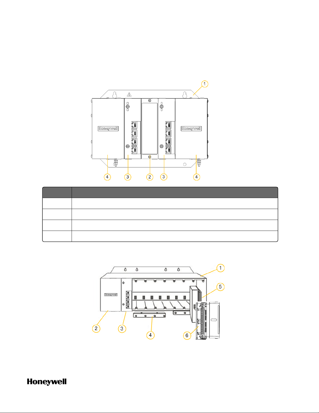
Item Model number Description
1 900RR0-0200 Redundant CPM Rack
2 900R04-0200 I/O Rack (4-slot)
15
Page 16

Chapter 3 - Hardware
Item Model number Description
3 900R08R-0200 I/O Rack (8-slot) can include either a redundant power
4 900R12R-0200 I/O Rack (12-slot) can include either a redundant power
supply or non-redundant power supply. A Power Status
Module (PSM) is required with redundant power
supplies.
The diagram shows the rack with a redundant power
supply.
The model number of the rack with a non-redundant
power supply is 900R08-0200.
supply or non-redundant power supply. A Power Status
Module (PSM) is required with redundant power
supplies.
The diagram shows the rack with a redundant power
supply.
The model number of the rack with a non-redundant
power supply is 900R12-0200.
Hardware components
This section provides a description of the major components that can
be included in a ControlEdge 900 Controller physical configuration
and indicates how the components can be combined. Some of the
components are required in all configuration. Others are optional and
can be used to provide additional functions, or to "size" the system, or
to modify or expand the system to meet changing requirements.
Rack
There are two types of racks:
n Redundant CPM Rack
Rack installed redundant CPMs
n I/O Rack, containing 4, 8 or 12 slots
I/O racks can include a topology with; either a non-redundant
power supply or with redundant power supplies, accommodate a
CPM or an EPM, and additional input/output modules. The I/O
rack inserted with an EPM enables I/O modules to be located
close to the field devices and remote from the CPM.
16
Page 17
Chapter 3 - Hardware
Slot number from left to right is 1~n, and n stands for the quantity of
the slots.
Figure 3-1: Redundant CPM Rack Components
Item Description
1 Redundant CPM rack
2 Redundant Switchover Module Slot Filler
3 Primary/Secondary CPMs
4 Two Power Supplies
Figure 3-2: I/O rack with non-redundant power supply
17
Page 18
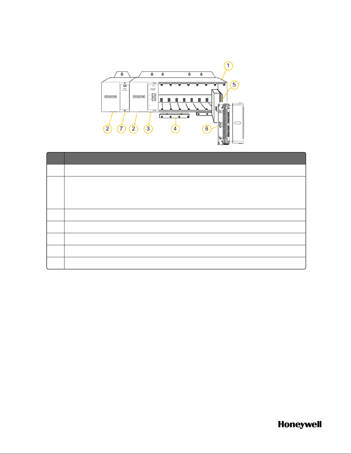
Chapter 3 - Hardware
Item Description
1 Rack, available in 4-, 8- or 12-slot versions
2 Power Supply
Figure 3-3: I/O rack with redundant power supplies
Redundant power supply is optional and only available in 8- or 12-slot racks.
You can only install one power supply in either of the two slots.
3 CPM or EPM with Security Cover
4 Grounding bars (for I/O wiring; optional; required for safety applications)
5 Input/Output modules
6 I/O Terminal Blocks
7 Power Status Module (PSM) (required if using redundant power supply)
Control Processor Module (CPM)
CPM (900CP1-0200) contains most of the electronics required to
perform the function of a process controller. A redundant CPM rack
contains two CPMs. Either CPM can be primary.
The CPM is shown in the following figure.
18
Page 19

Chapter 3 - Hardware
Item Description
1 Status LED indicator for the CPM.
2 Role LED indicator for the CPM.
3 SD card slot: supports 32GB Class 6 / Class 10 industry standard, not hot-
swappable, maximum weight 3g (0.0066 lb, 0.1058 oz)
An SD card can be inserted and used to reset the controller to factory settings, or
save datalog or DNP3 event.
CAUTION: Do not insert or remove the SD card when the CPM is powered
unless the area is known to be non-hazardous.
4 Mode switch.
There are four mode switch positions on CPM: STOP, RUN, and two REMOTE
positions. Two REMOTE positions are identical.
Rotate the four positions in clockwise or counter-clockwise. When the mode
switch is in REMOTE position, the operating modes can be configured in the
Configuration tool. For more information for the operating modes, see “Selecting
operating modes” in ControlEdge Builder User’s Guide.
ATTENTION: For redundant controller system, the position of mode
switch in primary CPM determines the system operating mode. If the
19
Page 20
Chapter 3 - Hardware
Item Description
mode switches on the primary and secondary CPMs are in different
positions, the system will drop sync.
5 First (ETH1) and second Ethernet (ETH2) Host ports to PC applications and/or
other CPMs, or other devices.
6 Third (ETH3) and fourth (ETH4) ports connect to the Ethernet ports of EPM,
switch (for star topology), or CPM (for the interconnection between redundant
CPM in Ring topology).
7 Ethernet LED status indicators for communications functions.
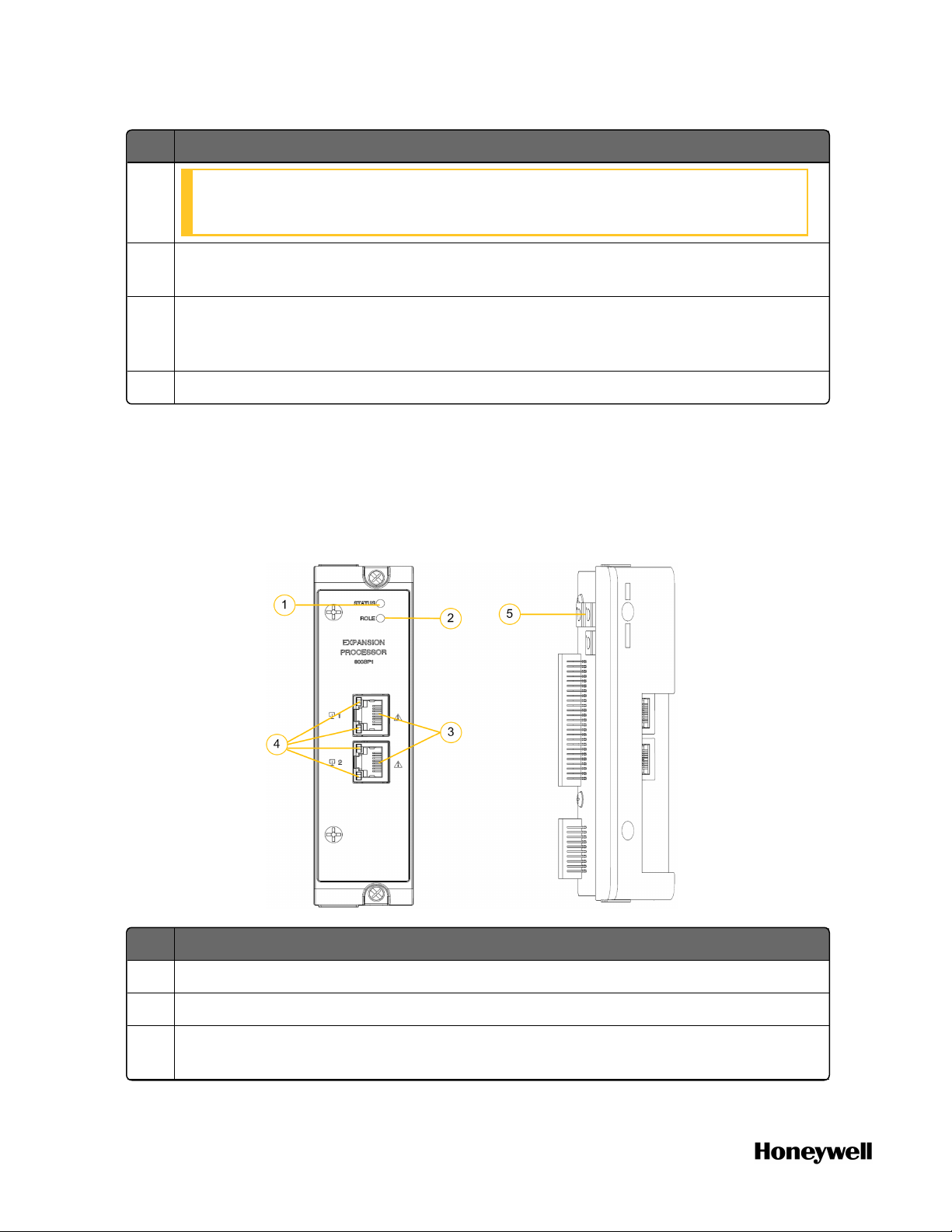
Expansion Processor Module (EPM)
EPM (900SP1-0200) is installed in the expansion I/O rack and
provides the link between the CPM and remote I/O modules.
The EPM is shown in the following figure.
Item Description
1 Status LED indicator for EPM functions.
20
2 Role LED indicator for EPM functions.
3 Ethernet 10/100 Base-T Ports; connect to the ports on other EPMs, CPM, or a
switch that connects to the CPM (for star topology).
Page 21
Item Description
4 Ethernet LED status indicators for communications functions.
Chapter 3 - Hardware
5
Rotary switch: used to set the EPM address and network topology for the I/O
rack.
Set the 10x and 1x switches to the two digit address ranging from 01 to 99. The
lower switch (10x) is used to set the tens digit and the upper switch (1x) sets the
ones digit. A small slotted screwdriver works well; avoid pencils.
Set the network topology using the 100x switch. 3 is for Ring network topology
and 4 is for Star network topology.
Input/Output module
ControlEdge PLC supports the following I/O modules.
For more information, see "I/O module specification" in the
ControlEdge 900 Platform Hardware Planning and Installation Guide.
Model number I/O module
900U01-0100 Universal Input/Output Module (UIO)
900A01-0202 Universal Analog Input Module (UAI)
900A16-0103 High Level Analog Input Module (16 channels)
900B01-0301 Analog Output Module (4 channels)
900G03-0202 Digital Input Module (16 channels) - AC Voltage Type
900G32-0101 Digital Input Module (32 channels) - DC Voltage Type
900G01-0202 Digital Input Module - Contact Type (16 channels)
900H03-0202 Digital Output Module (8 channels) - AC Voltage Type
21
Page 22
Chapter 3 - Hardware
Model number I/O module
900H32-0102 Digital Output Module (32 channels) - DC Voltage
900H01-0202 Relay Output Module (8 channels)
900K01-0201 Pulse Input/Frequency Input Module (4 channels)
Type
Power supply
Both AC power supply (900P01-0301) and DC power supply (900P24-
0301) can be used in Redundant CPM rack, Local I/O rack and
Expansion I/O rack.
For more information, see "Power supply" in the ControlEdge 900
Platform Hardware Planning and Installation Guide.
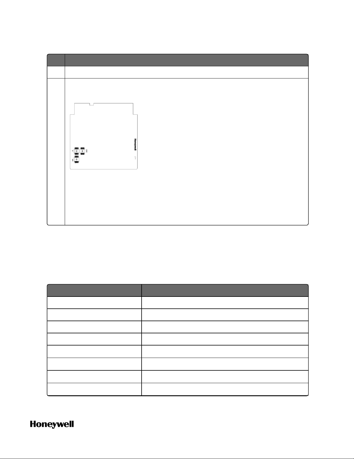
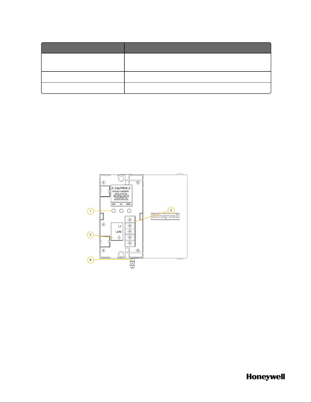
Figure 3-4: AC Power Supply
22
Page 23
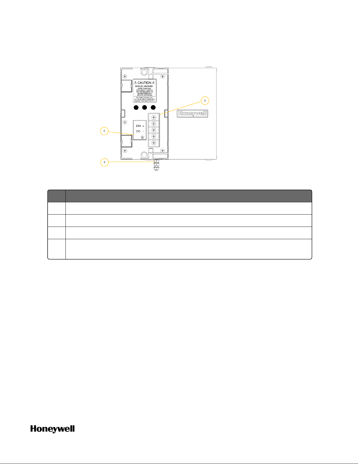
Figure 3-5: DC Power Supply
As indicated in the figures, the power supplies include:
Chapter 3 - Hardware
Item Description
1 Voltage test points
2 AC/DC Input terminal block
3 Wiring label
4 Grounding lug (Reference; lug is not part of power supply; it is mounted to
bottom of rack.)
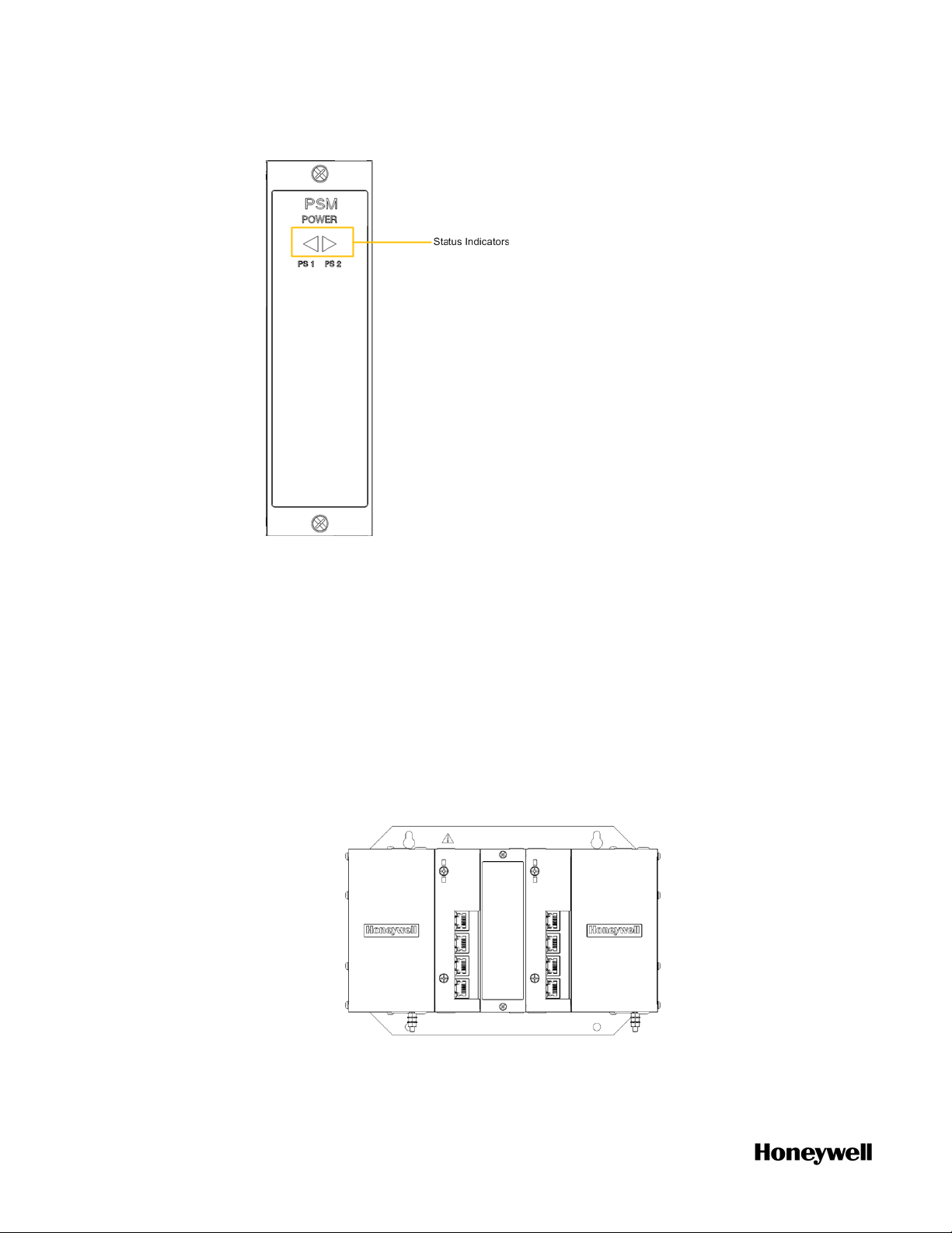
Power Status Module (PSM)
The PSM (900PSM-0200), shown in the following figure, sits between
redundant power supplies on the I/O rack. It is a status module for
both power supplies and indicates which are powered, PS-1 (left) or
PS-2 (right) or both (typical).
When the status indicator for either or both of the power supplies is
lit, it is reporting that the status of the associated power supply is
good and that the outputs are within specified limits. When the status
is off, either the power supply is off or the voltages are out of
tolerance.
23
Page 24
Chapter 3 - Hardware
Figure 3-6: Power Status Module
Installing the assembly
This section introduces you to mount the assembly.
1. Mount the rack in the enclosure.
2. Check if your configuration needs a redundant controller.
l If yes, assemble the redundant CPM rack.
a. Insert the power supplies in the slots in the rack.
b. Insert the CPMs in the rack, adjacent to the power supplies.
c. Insert the filler block cover in the middle slot.
24
l If no, assemble I/O racks, take the 8-slot I/O rack as an
Page 25

Chapter 3 - Hardware
example.
a. Insert the power supply.
b. Insert the PSM between the two power supplies.
c. If a CPM will be inserted, set the mode switch for CPM
optionally.
d. If a EPM will be inserted, set the EPM address and network
topology for the I/O rack using the rotary switch.
e. Insert CPM or EPM as required.
3. Install I/O modules.
ATTENTION: For each configured and labeled I/O module,
ONLY break off the "key-tabs" in the pattern that matches
that module type. For more information, see "Installing I/O
modules" in the ControlEdge 900 Platform Hardware
Planning and Installation Guide.
Wiring and cabling
Terminal Block Wiring can be routed through the terminal block at
the top, at the bottom, or both. Wiring should be fixed in place using
wire ties at the slotted tabs that are molded in at top and bottom of
each terminal block. The terminal block is removable.
The optional Remote Termination Panel (RTP) provides an easy way to
connect the ControlEdge 900 Controller to the field wiring. The RTP
integrates some of the typical externally connected components,
reducing wiring and setup time. It also minimizes the need for
multiple wires under a single screw connection by expanding the
connectivity of the shared terminals of the I/O modules.
25
Page 26
Chapter 3 - Hardware
Routing and securing wires
Typically, field wiring is routed to connections at a terminal panel near
the racks, and then from the terminal panel to the terminal blocks on
the I/O modules.
Whatever method of routing is used, wiring must be mechanically
supported along its length, and must be protected from physical
damage and electromagnetic (noise) interference.
ATTENTION: All wires must be securely terminated, using
appropriate wiring practices.
Wire shield grounding
Aluminum grounding bars for I/O wiring are available as options.
When selected for use, they are fastened to the top and/or bottom of
each rack, as indicated in the following figure. To enable connection
of multiple ground wires with a single screw, the wires can be twisted
together and secured with a wire lug.
Figure 3-7: Wire-Shield Grounding
To facilitate module replacement, it is advisable in most cases to route
all wiring through either the top or the bottom of the terminal block.
This allows the terminal block to pivot up or down, allowing ready
access to the module, and is the preferred method for a limited
number of wires.
26
Page 27

Chapter 3 - Hardware
For more information about each I/O module wiring, see "Terminal
Block-to-Field (Signal) Wiring" in the ControlEdge 900 Platform
Hardware Planning and Installation Guide.
I/O network Topology
ControlEdge PLC can be configured as a redundant controller system
or non-redundant controller system. It includes provisions for
communication via Ethernet with host systems and the Ethernet ports
provide a layer of protection against cyberattacks. Honeywell
recommends use of Solarwinds and/or Honeywell Risk Manager to
detect unintended and excess network traffic.
ControlEdge PLC supports star and ring I/O topologies for I/O
communication.
Star Topology
The following diagram shows an example of the star topology. A
switch is required for this topology.
27
Page 28

Chapter 3 - Hardware
Figure 3-8: Single star topology
28
Page 29
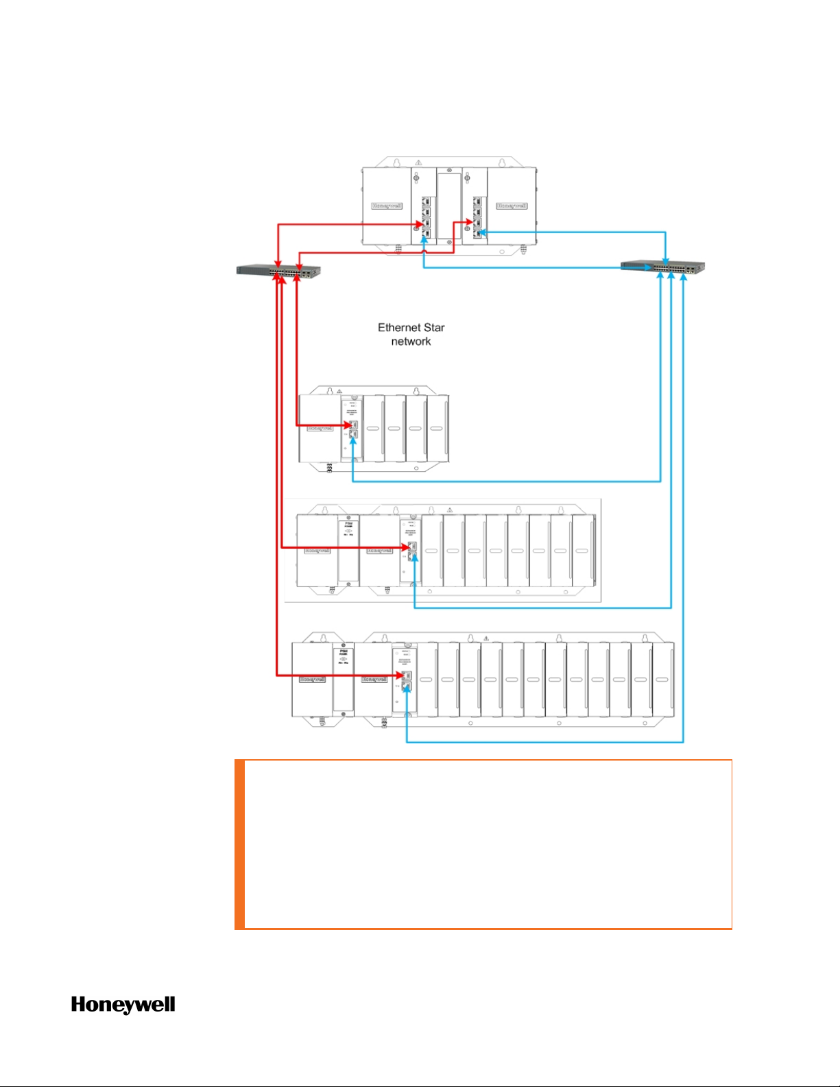
Figure 3-9: Redundant Star topology
Chapter 3 - Hardware
CAUTION: ControlEdge PLC-I/O network is a private network, and
the switch used for the interconnection of CPM and EPM must
not be connected to any other LAN or WAN. Likewise, no devices
or communication traffic other than the ControlEdge PLC
components should be connected to the I/O network switch.
Failure to comply will cause communication failures on the I/O
network causing I/O modules to go in and out of their failsafe
settings.
29
Page 30

Chapter 3 - Hardware
Ring Topology
The following diagram shows an example of the ring topology.
30
n CPM port 3 (ETH3) must be connected to CPM port 4 (ETH4) or
EPM port 2 (ETH2).
n CPM port 4 (ETH4) must be connected to CPM port 3 (ETH3) or
EPM port 1 (ETH1).
n EPM port 1 (ETH1) must be connected to EPM port 2 (ETH2) or
CPM port 4 (EHT4).
n EPM port 2 (ETH2) must be connected to EPM port 1 (ETH1) or
CPM port 3 (EHT3).
For more information, see “Planning for network topology” in the
ControlEdge 900 Controller Hardware Planning and Installation Guide.
Page 31

Chapter 3 - Hardware
Power on
Both AC power supply and DC power supply can be used in
ControlEdge PLC.
1. Connect 24 VDC supply or 120/240 VAC power supply to the
controller.
2. Connect an Ethernet cable to the CPM port most appropriate for
your situation.
3. Connect the other end of the Ethernet cable to the PC installed
ControlEdge Builder directly or through a switch.
ControlEdge 2020 platform
The Honeywell ControlEdge 2020 process controller is a modular,
powerful, and scalable system capable of all remote automation and
control applications. When combined with Experion® PKS and its
simplified SCADA configuration, it solves the remote automation
requirements.
ControlEdge RTU supports controller redundancy, Honeywell wired
and wireless I/O and enhanced Experion SCADA integration.
See the following figure for reference as a redundant controller
system.
31
Page 32

Chapter 3 - Hardware
Figure 3-10: Redundant ControlEdge 2020 Controller System Diagram
Item Model Number Description
1 SC-UCNN11 ControlEdge 2020 Redundant Controller
2 SC-UMIX01 ControlEdge 2020 Mixed I/O Module with 28 I/O
3 SC-TEPR01 ControlEdge 2020 expansion I/O right end plate, includes
a CAT-5 termination cable
4 SC-TEPL01 ControlEdge 2020 expansion I/O left end plate
Hardware components
ControlEdge RTU system consists of a controller, expansion I/O
modules, right end plate, and left end plate. These components are
combined with field devices to make a complete system.
Redundant Controller
The redundant controller consists of two CPMs and an IOTA.
32
Page 33

Figure 3-11: Redundant Controller
Item Description
1 18-30 VDC power supply (two)
Chapter 3 - Hardware
2 RS485 Ports (two)
3 RS232 Ports (two)
4 Ethernet Ports (four) Ethernet port1 and port2 for the left CPM (SLOT1).
Ethernet port3 and port4 for the right CPM (SLOT2).
5 Screw hole: used for locking controller IOTA and expansion I/O IOTA.
6 Expansion Connector: used for connecting with expansion I/O module.
Expansion I/O
An Expansion I/O consists of an IOM and an IOTA.
An I/O Module (IOM) contains most of the electronics required to
perform a specific I/O function. The IOM plugs onto the IOTA.
ATTENTION: Up to 30 expansion IOMs of Revision B can be
connected with the controller.
33
Page 34

Chapter 3 - Hardware
Item Description
1 Chassis ground
Figure 3-12: Expansion I/O
2 Left expansion connector: used for connecting with controller, expansion I/O
module or left end plate.
3 Rotary switch (two): used for setting the address of IOM. The controller can
configure and communicate with IOM according to this address. Set the
switches to the two digit address ranging from 01 to 98. The upper switch (10) is
used to set the tens digit and the lower switch (1) sets the ones digit. See
"Mounting the Controller with Expansion IOM" on page1 for more information.
ATTENTION:
l The address must be unique across all I/O modules connected to
the same ControlEdge 2020 controller.
l Unless the location is known to be non-hazardous, do not adjust the
switches while the equipment is powered.
l Do not set the switch index bigger than 98, or else the system LED
of IOM status indicator would blink with yellow, reflecting that IOM is
unable to establish the communication with the Controller.
4 Terminal strips: used for connecting I/O cable from the field.
5 Screw holes: used for locking IOTAs between two expansion I/O Modules.
34
6 Right expansion connector: used for connecting with expansion I/O module or
right end plate.
Page 35

Chapter 3 - Hardware
ATTENTION: The non-redundant controller IOTA (51307198-
175) must be at hardware version ‘B’ or later to work with
expansion I/O modules. The hardware version is detailed on the
controller IOTA label.
Expansion IOMs and CPMs communicate via a ring topology
providing two link paths. If the running link path breaks, the other link
path re-establishes communication within in 250ms.
Right End Plate
A right end plate is required at the end of each row of expansion I/O
modules including the row connected to a controller. It allows
additional rows to be added or terminates the I/O link. The right end
plate has two Ethernet ports and a left expansion connector, as
numbered in the following picture.
Figure 3-13: Right End Plate
Item Description
1 Left expansion connector: connects to a controller or an expansion I/O module.
2 Ethernet port 1: allows additional rows to be added or terminates the I/O link.
3 Ethernet port 2: allows additional rows to be added or terminates the I/O link.
35
Page 36

Chapter 3 - Hardware
ATTENTION: Two ports of the last right end plate should be
connected with a termination cable to complete ring formation.
Left End Plate
Left end plate is used only in multi-row ControlEdge 2020 systems for
the IOM power supply and Ethernet connection. Left end plate has an
18-30 VDC Power Input, two Ethernet ports and a right expansion
connector, as numbered in the following picture.
Figure 3-14: Left End Plate
36
Item Description
1 18-30 VDC power supply
2 Right expansion connector: connects to an expansion I/O module.
3 Screw holes: used for locking left end plate and expansion I/O IOTA.
4, 5 Ethernet port 1 and Ethernet port 2: extends the I/O link to another row.
Page 37

Chapter 3 - Hardware
Installing the assembly
This section introduces you to mount the assembly.
To install the controller with expansion I/O modules
1. Remove the connector cover on the right side of controller IOTA.
2. Mount the controller IOTA onto the DIN rail.
3. Mount the expansion I/O IOTAs onto the DIN rail and insert the
IOTA into the controller IOTA.
4. Set the rotary switch to the address of the IOM, ranging from 1 to
99.
5. Insert the CPM onto the IOTA and secure it.
6. Insert IOM onto the expansion I/O IOTA and sure it.
Wiring and cabling
All I/O channels share the power source with the system components
while the two analog output devices are powered internally. In most
cases, the other 26 channels require external cabling to introduce the
voltage to field loops from the system power source.
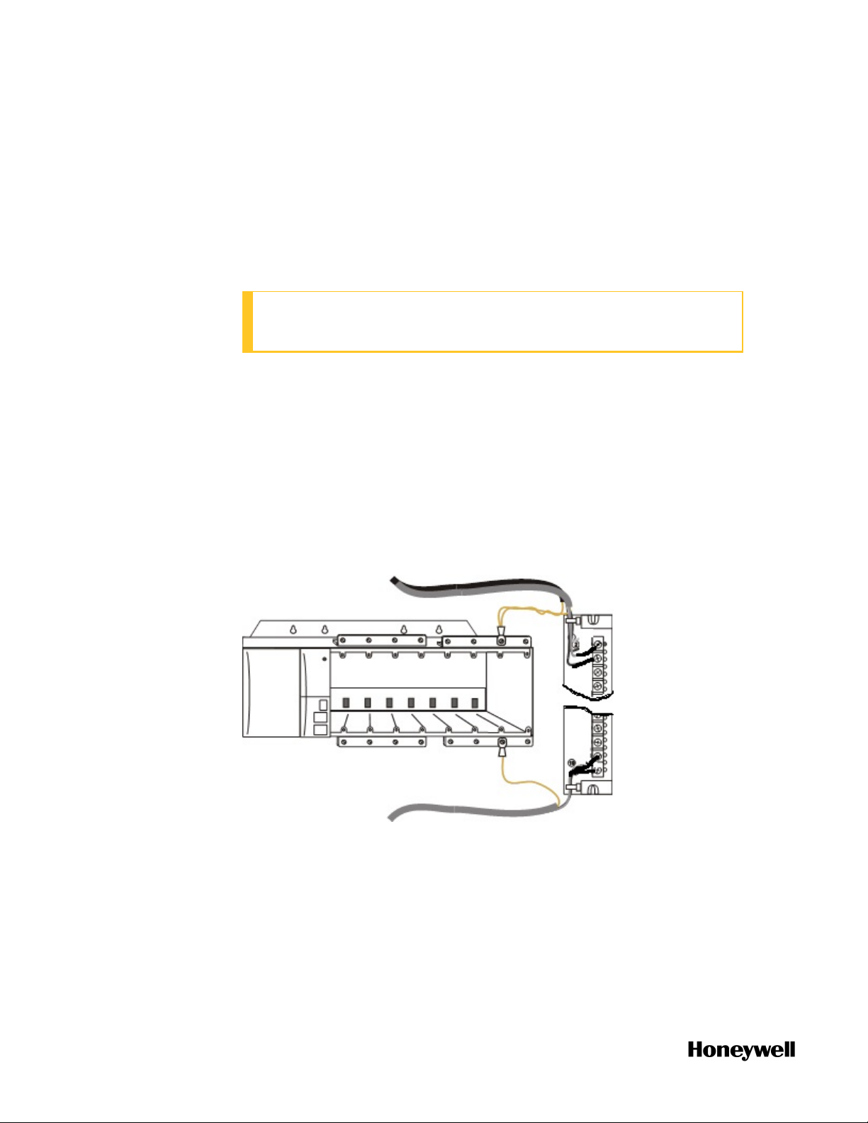
Grounding and Shielding
CAUTION: ControlEdge 2020 controller must be connected to
earth ground.
Connect ControlEdge 2020 Controller to earth ground through power
input terminal chassis ground pin (pin 33) as illustrated in the
following figure.
Figure 3-15: Redundant Controller Grounding
Connect Expansion I/O to earth ground through pin 31 as illustrated
in the following figure.
37
Page 38

Chapter 3 - Hardware
Figure 3-16: Non-redundant Controller Grounding
Figure 3-17: Expansion I/O Grounding
For more information about each I/O module wiring, see "I/O Wiring"
in the ControlEdge 2020 Platform Hardware Planning and Installation
Guide.
38
Page 39

Chapter 3 - Hardware
I/O network topology
ControlEdge RTU can be configured as a redundant controller system
or non-redundant controller system.
ControlEdge RTU supports ring I/O topology for I/O communication.
The following diagram shows an example of the topology.
For more information, see “Planning for network topology” in the
ControlEdge 2020 Controller Hardware Planning and Installation
Guide.
Power on
1. Connect 24 VDC supply to the controller.
2. Connect an Ethernet cable to the port most appropriate for your
situation.
3. Connect the other end of the Ethernet cable to the PC installed
ControlEdge Builder directly or through a switch.
39
Page 40

Chapter 3 - Hardware
40
Page 41

CHAPTER
SOFTWARE
4
Installing ControlEdge Builder
The following table lists the operation system and resolution
requirements for the PC installed ControlEdge Builder.
Item Specification
Operation system
Resolution Recommended: 1280x800 or above
Windows 7 32-bit or 64-bit with SP1
Windows 2008 32-bit or 64-bit with SP1
Windows 10 32-bit or 64-bit (Support secure communication)
Windows Server 2016 Standard Edition 64-bit
Optimal: 1920x1080, 1366x768, 1280x1024 and 1280x800
To install ControlEdge Builder
1. Insert the ControlEdge Builder Media Kit into the DVD-ROM drive.
2. Browse to the folder containing ControlEdge_builder_setup.exe.
Double-click this file.
3. Follow the screen prompts to install ControlEdge Builder.
For full instructions on how to install ControlEdge Builder, see the
ControlEdge Builder Software Installation User’s Guide.
Launching ControlEdge Builder
Click Start > All Programs > Honeywell > ControlEdge Builder > ControlEdge
Builder to launch ControlEdge Builder and the Start Page appears.
Start Page is outside any project context, and enables the user to
select an action to start. It provides several actions:
n Create Project: click the icon to create a new project with the
default controller configuration.
n Open Project: click the icon to open an existing project.
n Connect: click the icon to connect to a controller.
41
Page 42

Chapter 4 - Software
Checking firmware versions
Figure 4-1: Start Page
Before configure the controller, make sure all the hardware modules
used in the system are installed with the right firmware version.
Otherwise, you should upgrade the firmware first. See "Upgrading
firmware" on page70 for more information.
Creating a project
This section introduces how to create a new project. The
configuration and programming details are stored in the project.
To create a new project
1. From the Start Page, click Create Project.
2. In the Create New Project from Template window, click General and
select the target template from the Available Templates list.
l Select 900cp1 to create a project for a ControlEdge 900
controller.
l Select SC-UCMX01 or SC-UCNN11 to create a project for a
ControlEdge 2020 controller.
l SC-UCMX01 is for a non-redundant controller.
l SC-UCNN11 is for a redundant controller.
3. Click Next. The Save As window appears.
4. Select an appropriate directory to save the project and enter a
name for the project in the File name field.
42
Page 43

Chapter 4 - Software
l The project name must not contain any of the following
characters: '.\/:*?"<>|'.
l The project name must not exceed 24 characters.
l The directory path length must not exceed 171 characters.
5. Click Save. A project is created and the Home Page appears. Take
the home page of ControlEdge 900 controller as an example here.
Item Description
1 This area contains toolbar and menu bar. You can
navigate to IEC Programming Workspace, compile a
project, build a project, debug on/off, etc.
2 This area contains the following options: open an
existing project, connect a controller, upgrade a
project and download a project.
3 This area contains configuration options for the
controller and project. You can configure the IP
address, configure I/O, upgrade firmwares and
program the project, etc.
For more information, see "Creating a project" in the ControlEdge
Builder User's Guide.
43
Page 44

Chapter 4 - Software
Configuring hardware
Setting controller name
You can set a new name for a controller.
1. From the Home Page, under Controller and Programming, click Set
Controller Name.
2. Enter the desired name for the controller, and click Save.
If using Experion integration with ControlEdge 900 or 2020
controller, this name is used to identify the controller during Experion
configuration.
Configuring the controller IP address
The first thing you will normally want to do is set the IP address for
the controller. The following steps describe how to configure a fixed
IP address starting with creating a new project.
The following table lists the factory default network settings. If your
controller has been previously configured, these settings may have
been changed.
Table 4-1: Factory default network settings of the non-redundant controller
Port Default setting
ETH1 IP address is dynamically assigned from a DHCP server.
If no DHCP server is found by the controller, an IPv4 link-local address will be
assigned (169.254.x.x).
ETH2 Static IP address: 192.168.1.50
Table 4-2: Factory default network settings of the redundant controller
Port Default setting
ETH1 IP address is dynamically assigned from a DHCP server.
If no DHCP server is found by the controller, an IPv4 link-local address will be
assigned (169.254.x.x).
44
The secondary controller IP address is incremented by 1 from the primary
controller IP address.
ETH2 The primary controller static IP address: 192.168.1.50
Page 45

Port Default setting
The secondary controller static IP address: 192.168.1.51
To configure IP address
1. From the Home Page, click the arrow beside Configure Ethernet
Ports, and select ETH1 or ETH2.
2. Under Network Setting, configure the IP address of the Ethernet
port for the controller.
3. Under the Protocol Binding, select the protocol which you want to
bind to the port.
4. Click Save to complete the Ethernet port configuration.
5. Click Back to return to the Home Page.
TIP: If new IP settings are compiled and downloaded, the
controller will be disconnected from the configuring device.
Chapter 4 - Software
Configuring controller start up
This function enables you to configure the controller status after the
power cycle.
For ControlEdge 900 controller, this feature is only applicable when
the mode switch is in REMOTE position.
Under Controller and Programming, select Configure Controller Start Up,
the Configure Controller Start Up page appears. There are four options
for controller start up:
n
Last operating mode, or Running after an abnormal stop
This option is the default setting for ControlEdge 2020 controller.
The controller will start in the operating mode that it was last in
prior to a power off, unless there was an abnormal stop caused by
a system error such as a watchdog timeout issue. It will then start
in Running mode.
l If the controller was in Running mode before power off, the
controller will warm start in Running. If the warm start fails, the
controller will go to Stopped mode.
l If the controller was stopped manually before power off, the
controller will start in Stopped mode.
l If the controller was stopped abnormally before power off, the
45
Page 46

Chapter 4 - Software
controller will warm start in Running mode. If the warm start
fails, the controller will go to Stopped mode.
n
Last operating mode, or Stopped after an abnormal stop
This option is the default setting for ControlEdge 900 controller.
The controller will start in the operating mode that it was last in
prior to a power off, unless there was an abnormal stop caused by
a system error such as a watchdog timeout issue. It will then start
in Stopped mode.
l If the controller was in Running mode before power off, the
controller will warm start in Running. If the warm start fails, the
controller will go to Stopped mode.
l If the controller was stopped manually before power off, the
controller will start in Stopped mode.
l If the controller was stopped abnormally before power off, the
controller will start in Stopped mode.
n
Running
The controller will warm start in Running mode. If the warm start
fails, the controller will go to Stopped mode.
n
Stopped
The controller will start in Stopped mode.
ATTENTION: If you reboot the controller manually, the
configuration in this section will not take effect. For example: If
you select Running here, and you select Reboot Controller under
Maintenance, and click Cold Reboot. The controller will perform
cold start, but not warm start after it reboots.
Configuring controller redundancy
To disable redundancy
1. Under Controller and Programming, select Configure Controller
Redundancy.
2. Select Disable Controller Redundancy to disable the redundancy
function.
46
3. Click OK. Redundancy has been disabled. The IP address
configured for the secondary controller will be disabled.
To enable redundancy
Page 47

Chapter 4 - Software
1. Under Controller and Programming, select Configure Controller
Redundancy.
2. Select Enable Controller Redundancy, and then click OK.
The configuration of I/O modules in the rack local to the
controller will be removed and a static IP address must be
configured for the secondary controller.
3. Configure the IP address of the controllers.
l If the Obtain an IP Address Automatically options of ETH1 and
ETH2 were enabled, this option will be disabled automatically.
Configure Primary Controller IP Address and Secondary Controller
IP Address manually.
l If the Obtain an IP Address Automatically options of ETH1 and
ETH2 were disabled, configure the Secondary Controller IP
Address manually.
Configuring an I/O module
Configure an I/O module for ControlEdge 900
controller
1. From the Home Page, under I/O and Communications and click
Configure Modules > Configure I/O Modules.
2. Click Add I/O Module, the Add I/O Module dialog appears.
3. Select the Type, assign the Rack and Slot, and set the IOM Scan Time
for the Module.
4. Click OK to add the I/O module.
5. Select the corresponding I/O module, configure I/O channels.
Configure an I/O module for ControlEdge 2020
controller
You can configure onboard I/O modules, expansion I/O modules and
a third party I/O ST103A for ControlEdge 2020 controller.
To configure an onboard I/O
1. From the Home Page, under I/O and Communications and click
Configure I/O.
47
Page 48

Chapter 4 - Software
2. Click Onboard I/O and you can view the five channels AI, AO, DI, DO
and PI.
3. Select the corresponding channel, and configure parameters.
To add and configure an expansion I/O module
1. From the Home Page, under I/O and Communications and click
Configure I/O.
2. Click Add I/O Module > SC-UMIX01 Mixed I/O Module, 28, the Add I/O
Module dialog appears.
3. Enter the Description and select the Address for the I/O module
which must be same as the rotary switch setting of the physical
device. The range of the address is from one to nine.
4. Click OK to add the I/O module.
5. Click the corresponding expansion I/O module to view channels.
6. Select the corresponding channel, and configure parameters.
To add and configure an third-party I/O, ST103A
1. From the Home Page, under I/O and Communications, click
Configure Third-Party I/O > ST103A.
2. Click Add ST103A Module. The Add I/O Module dialog appears.
3. Enter Description for ST103A module which will be a unique
identifier for binding with specific meter runs.
4. Select Slave ID for the drop-down list. The valid value is from 1 to
15.
The ST103A should be opened to set Slave ID and row 4 bit
switches will be available to configure the value from 1 to 15. See
"Configuring ST103A" in the ControlEdge 2020 Platform Hardware
Planning and Installation Guide for how to set Slave ID.
ATTENTION: If there are other Modbus devices connected to
the same RS485 port along with ST103A, ensure that they
do not conflict with each other.
5. Select the port number, and provide values for Retries and Timeout.
6. Click OK to add ST103A module.
48
7. Click the corresponding module to view channels.
Only ST103A's analog input, pulse input, frequency and raw pulse
Page 49

Chapter 4 - Software
output can be configured via ControlEdge Builder.
8. Select the corresponding channel, and configure parameters.
Configuring serial modules
The section introduces how to add and configure a serial
communication module. Up to six serial modules can be added.
1. From the Home Page, under I/O and Communications, click
Configure Modules > Configure Serial Modules.
2. Click Add Serial Module, the Add Serial Module dialog appears.
3. Select the Type, assign the Rack and Slot for the module.
See the following table for the parameter descriptions:
Parameter Description
Type Serial module type: 900ES1: Serial Comm
Rack Rack address:
l If controller redundancy is enabled, the rack
address range is from 1 to 99.
l If controller redundancy is disabled, the rack
address range is from 0 to 99. 0 is only for the
local I/O rack.
l For an expansion I/O rack, the address must be
the same with the EPM address configured on
1x and 10x rotary switches.
For details about the rotary switches, see
“Assembling I/O racks” in the ControlEdge 900
Controller Hardware Planning and Installation
Guide.
Slot Slot number: the location of the I/O module mounted
in the rack
l If the I/O module is installed in a 4-slot rack, the
slot number is ranging from 1 to 4.
l If the I/O module is installed in an 8-slot rack,
the slot number is ranging from 1 to 8.
l If the I/O module is installed in a 12-slot rack,
the slot number is ranging from 1 to 12.
49
Page 50

Chapter 4 - Software
4. Click OK to add the serial module.
5. Select a serial module. There are four serial ports to be configured,
RS232-1, RS232-2, RS485-1 and RS485-2. Select the target port
and configure appropriate values for the following parameters.
Parameter Description
Baud
Rate
300, 600, 1200, 2400, 4800, 9600, 19200, 38400,
57600, 115200
Parity None, ODD, EVEN
Data Bits 7, 8
If you select Modbus RTU Slave or Modbus RTU
Master for the Protocol Binding, the Data Bits is set
as 8 by default.
Stop Bits 1, 2
For RS232-1 and RS232-2, you should configure one more
option: Flow Control. See the following table for the parameter
descriptions.
Parameter Description
Flow Control Only for RS232-1 and RS232-2
l None
l RTS-CTS
50
l RTS
6. Under Protocol Binding, select a protocol from the Port Protocol
drop-down list.
The following table provides information about various protocols
supported by serial ports.
Protocol Description
Modbus
RTU
The controller acts as the Modbus Slave and used for
communication between:
Slave
l Controller and SCADA
l Controller and third-party Modbus Master
devices
Page 51

Protocol Description
If you select Modbus RTU Slave:
l Data Bits is set as 8 by default.
l There are two more options to configure: Slave ID
and Mapping.
If the Mapping is empty, you must add a mapping
table first. See "Adding a Modbus Slave mapping
table" on page1 for more information.
Chapter 4 - Software
Modbus
RTU
Master
Modbus
ASCII
Slave
Modbus
ASCII
Master
User
Defined
The controller acts as the Modbus Master and used for
communication between The controller and third-party
Modbus Slave devices, for example I/O modules.
If you select Modbus RTU Master, Data Bits is set as 8
by default.
The controller acts as the Modbus Slave and used for
communication between:
l Controller and SCADA
l Controller and third-party Modbus Master
If you select Modbus ASCII Slave, you must configure
two more options: Slave ID and Mapping. If the Mapping
is empty, you must add a mapping table first. See
"Adding a Modbus Slave mapping table" on page1 for
more information.
The controller acts as the Modbus Master and used for
communication between The controller and third-party
Modbus Slave devices, for example: I/O modules.
User Defined protocol.
When you select this option, the Delimiter Mode
(Optional) panel appears including three settings: Readinterval Timeout (ms), Max Length (Bytes) and End
Delimiter (Hex). You can configure them optionally to
validate if a data frame is sent completely.
l Read-interval Timeout (ms): The interval between the
last data packet sent and the first keepalive probe,
ranging from 0 to 10000 (ms). If the interval
between the arrivals of any two bytes exceeds this
51
Page 52

Chapter 4 - Software
Protocol Description
Timeout, system regards it has already received a
complete data frame.
The default value is 0 which means this option is
disabled.
l Max Length (Bytes): The maximum number of bytes
for a data frame, ranging from 0 to 532. If the length
of a received data frame exceeds the Max Length,
system regards it has already received a complete
data frame.
The default value is 0 which means this option is
disabled.
l End Delimiter (Hex): Configured special characters in
hexadecimal and based on bytes validates if a data
frame is sent completely. If the received data frame
has same characters with the End Delimiter, system
regards it has already received a complete data
frame.
The default setting is blank which means this option
is disabled.
For how to configure User Defined protocol, see
"User Defined Protocol" in the ControlEdge Builder
Function and Function Block Configuration
Reference.
7. Click Save to complete the configuration.
Configuring a controller simulator
Controller simulator can be deployed on a Virtual Machine, and
enables the user to configure a controller without connecting a
physical controller.
For this release, the controller simulator does not support I/O
communication.
52
Page 53

Chapter 4 - Software
ATTENTION: It is not recommended to use the simulator in a
production environment, because simulator does not support
secured communication.
The following table lists the supported and non-supported features of
the controller simulator.
Features Support
Connect a controller simulator Yes
Download a project to a controller simulator Yes
Download a redundant project to a controller simulator Yes
Debug a program Yes
Force I/O value through I/O variables Yes
Force I/O value through I/O channels No
Upload system event log Yes
Monitor link status Yes
System diagnostics Yes
Secure communication No
Communication between SCADA and controller simulator Yes
Communication between controller simulators Yes
Communication between virtual and physical controllers Yes
Modbus TCP master/slave Yes
Modbus UDP slave No
Enron Modbus slave No
DNP3 slave No
OPC UA Server Yes
OPC UA Client No
CDA responder No
EtherNet/IP No
HART/HART-IP No
53
Page 54

Chapter 4 - Software
Features Support
Wireless I/O No
Data logging No
EFM No
Secured communication No
Prerequisite
Make sure the IP addresses for the PCs installed simulator and
ControlEdge Builder are on the same subnet.
One virtual machine only supports one controller simulator.
Procedures
1. Install a virtual machine. Two virtual machines are verified:
l VMware Workstation Player 12.5.8 or higher hypervisor
l VMware vCenter Server 6.0.0 or higher hypervisor
For more information, see the vendor's documents.
2. Import or open an OVA file in the virtual machine, and play the
virtual machine. Honeywell provides three OVA files stored in
Simulator folder in the Media.
RXXX indicates the release number.
l ControlEdge 900 controller: ControlEdge_PLC_900CP1_
RXXX.ova
l ControlEdge 2020 controller:
l Non-redundant controller: ControlEdge_RTU_SCUCMX01_
RXXX.ova
l Redundant controller: ControlEdge_RTU_SCUCNN11_
RXXX.ova
Take VMware Workstation Player 12.5.8 as an example here:
a. Click Player > File > Open, the Open Virtual Machine dialog
appears.
54
Page 55

Chapter 4 - Software
b. Browse to the location stored the target OVA file, select the OVA
file and click Open.
c. From the Import Virtual Machine dialog, name the virtual
machine, and select a storage location for the virtual machine.
Click Import.
55
Page 56

Chapter 4 - Software
d. Click Play virtual machine.
56
e. For ControlEdge 900 controller, you should configure the
controller type.
l Enter 0 to configure the controller type as non-redundant.
l Enter 1 to configure the controller type as redundant.
Page 57

Chapter 4 - Software
NOTE: The controller type cannot be changed once you
configure it, and you should re-import the OVA file and
configure it again.
An OVA file defines a controller simulator. To change the
controller simulator version, import the corresponding OVA file.
For more information, see the vendor's documents.
3. Connect to a controller simulator. See "Connecting a controller"
on page1 for more information.
After you connect to a controller simulator, make sure the build
settings is I486_LE_GCC3. Click IEC Programming Workspace and
check the following parameter:
4. Configure a controller simulator. See the table above for the
supported configuration. Project version must match with the
controller simulator version.
5. Compile the project. See "Compiling a project" on page1 for more
information.
6. Download the project to the controller simulator. See
"Downloading a project to the controller" on page1 for more
information.
57
Page 58

Chapter 4 - Software
Programming with IEC 61131-3
This chapter introduces general information about programming with
IEC 61131-3.
See the embedded help for details about programming. Select Help >
Contents from the toolbar. In the pop-up help, expand Programming
System Help and click Programming a project.
Adding a library
The Libraries that are included in your project are either user-defined
libraries or firmware libraries.
n User Library: contains programs, function blocks, functions and
user-defined data types, and can be reused across projects.
Honeywell provides user libraries and user can create their own.
The file extensions for user library are *.mwt and *.mwe.
n Firmware Library: contains function blocks and functions
prepared by Honeywell for specific hardware. The file extension for
firmware library is *.fwl.
For more information about the function and function block, see the
ControlEdge Builder Function and Function Block Configuration
Reference Guide.
To add a library
1. Click IEC Programming Workspace from the toolbar, or from Home
Page, click Program with IEC61131-3.
2. Right-click Libraries and click Insert. Select User Library or Firmware
Library.
l For User Library, select .mwt file and click Include.
l For Firmware Library, click the corresponding folder and select
the target .fwl file, and then click Include.
Creating a data type
Honeywell provides some read-only user-defined data types, and user
can also create and define data types. The maximum number of user
defined data types is 1024. User-defined data types can be used
within user function blocks and programs. They cannot be used in
user functions.
58
To create a data type
Page 59

Chapter 4 - Software
1. Click IEC Programming Workspace from the toolbar, or from Home
Page, click Program with IEC61131-3.
2. From the Project Tree Window, right-click Data Type and select Insert
> Datatypes and name the target data type.
3. Double-click the newly added data type, you can edit it in the text
editor.
For I/O_DataTypes, each I/O Channel has one or two structures. All of
the related information for this channel is grouped together in the
structures as shown below. You can use this information as reference
for I/O channel configuration and programming.
Table 4-3: I/O channel structures of the I/O_DataTypes
Structure type Parameter Parameter type
ANALOG_INPUT_TYPE STS USINT
PV REAL
EUHI REAL
EULO REAL
EUHIEX REAL
EULOEX REAL
ANALOG_OUTPUT_TYPE OP REAL
ANALOG_OUTPUT_READBACK_
TYPE
STS USINT
OP_READBACK REAL
EUHI REAL
EULO REAL
EUHIEX REAL
EULOEX REAL
DIGITAL_INPUT_TYPE STS USINT
PV BOOL
DIGITAL_OUTPUT_TYPE OP BOOL
59
Page 60

Chapter 4 - Software
Structure type Parameter Parameter type
DIGITAL_OUTPUT_READBACK_TYPE STS USINT
PULSE_INPUT_TYPE STS USINT
OP_READBACK BOOL
COUNTER
RATE
PREI
PULSE_INPUT_CONTROL_TYPE RST
HOLD
4
1
2
3
UDINT
REAL
BOOL
BOOL
5
BOOL
FREQUENCY_INPUT_TYPE STS USINT
FREQUENCY REAL
PULSE_OUTPUT_TYPE PULSES UDINT
ENABLE BOOL
START BOOL
CONTINUE BOOL
PULSE_OUTPUT_READBACK_TYPE STS USINT
REMAIN UDINT
1. COUNTER: The accumulated Engineering Unit (EU) count.
60
2. RATE: Rate in EU/Time Period. Input pulses are counted over a specified Sample
Time and scaled to EU/Second, EU/Minute or EU/Hour.
3. PREI: Preset indicator. OFF [0] when COUNTER = less than the local or remote
preset value, ON when the count reaches the local or remote preset value. The
hardware module determines the state of the PREI output. PREI is cleared by the
RST input. A preset value of 0 effectively turns off the Preset allowing the counter to
count continuously until held or reset.
4. RST: An OFF to ON transition resets the module's pulse counter and the OUT to
zero. It also clears the FAIL, Overflow in STS and PREI.
5. HOLD: A Boolean value when set to 1 holds the EU count at its current value.
Page 61

Chapter 4 - Software
Creating a variable
This section introduces how to create and declare variables to
diagnose and monitor the system.
To create a variable
1. Click IEC Programming Workspace from the toolbar, or from Home
Page, click Program with IEC61131-3.
2. You can create local variables or global variables from the
corresponding grid worksheet. is the grid worksheet for local
variables, and is the grid worksheet for global variables.
For the following steps, let us take the global variable as an
example.
3. Double-click Global_Variables under Physical Hardware, the global
variable sheet appears.
4. Right-click under the corresponding group, and select Insert
variable to add a new I/O variable.
For output channel variables, you must add corresponding read
back variables with suffix “_READBACK” in the Input I/O Variables
group.
5. Double-click the Name and Description fields to modify, and select
Type and Usage from the drop-down lists.
The maximum quantity of characters for a variable name is 30.
IEC address of the I/O variable is generated automatically after
you bind it with an I/O channel and click Make. If you add a new
I/O variable by copying an existing bound one in a compiled
project, you should delete the IEC address of the new variable
manually and click Make to generate it automatically.
6. If a variable will be used for Modbus, EFM or PID, you should
select Retain for it. Perform either of the following methods:
l From the variable sheets, select Retain.
61
Page 62

Chapter 4 - Software
l From the variable properties dialog, select Retain, and click OK.
Creating a Programming Organization Unit
Logical Program Organization Units (POUs) are the language
elements of a program. They are small, independent software units
containing the program code. The name of a POU must be unique
within the project.
There are three different POU types:
n Program: contains a logical combination of function or function
block calls. Programs have input and output parameters and they
can have an internal memory.
n Function Block: POUs with multiple input/output parameters and
internal memory.
n Function: POUs with multiple input parameters and exactly one
output parameter.
To create a POU
1. Click IEC Programming Workspace from the toolbar, or from Home
Page, click Program with IEC61131-3.
2. From the Project Tree Window, right-click Logical POUs and select
Insert > Program/Function Block/Function, the Insert dialog appears.
62
3. Enter the Name for the new POU.
Page 63

Chapter 4 - Software
4. Select the desired programming Language. Depending on your
system configuration, some programming language are possibly
not available.
5. Enter a PLC type and/or a Process type if required.
6. Click OK, the new POU is inserted in the project tree. It contains
one code worksheet in the chosen language, a variable worksheet
and a description worksheet.
7. Expand the POU, and double-click the code worksheet, the
workplace appears.
8. Drag the target function or function block from the Edit Wizard
pane, and the function or function block is displayed.
9. Double-click the pin-outs of the function or function block, the
Variable Properties dialog appears.
10. Accept the proposed name, or enter a new name or select an
already existing name from the Name combo box.
11. Select the Data Type and Usage from the drop-down lists.
l If you are creating a Program, there are two options for Usage:
VAR and VAR_GLOBAL.
l If you are creating a Function Block, there are five options for
Usage: VAR, VAR_INPUT, VAR_OUTPUT, VAR_IN_OUT and VAR_
GLOBAL.
l If you are creating a Function, there are two options for Usage:
VAR and VAR_INPUT.
See the following table for the description of variables.
Variable Description
VAR Local variable
VAR_GLOBAL Global variable
VAR_INPUT Local FB input variable
VAR_OUTPUT Local FB output variable
VAR_IN_OUT Local input/output variable
12. Assign the initial value and I/O address.
13. It is optional to select the target group from Global Variable Groups.
Click OK and the new variables are added to the selected groups.
63
Page 64

Chapter 4 - Software
If you do not select a Global Variable Group, the variables are added
to the Common Variables group by default.
Associating a program to a task
Tasks determine the time scheduling of the programs associated with
them. This means that programs have to be associated to tasks in
order to be executed. The settings of the task determine the time
scheduling.
To create a task and associate a program
1. Click IEC Programming Workspace from the toolbar.
2. From the Project Tree Window, under Physical Hardware, right-click
Task and select Insert > Task.
3. Enter the Name.
Task name and Instance name must start with a letter or an
underscore. The rest of the characters can be letters, numbers or
underscores. The maximum quantity of characters which a task
name can have is 7 and that of a program instance is 24.
4. Select the Task type. See the following table for the descriptions of
task types.
Task type Description
DEFAULT Each resource can contain one default task. It is the
task with the lowest priority (lower than cyclic tasks)
and is not time scheduled.
CYCLIC Cyclic task executes their associated programs in
fixed time intervals.
EVENT Event task executes their associated programs each
time a particular event occurs.
SYSTEM System task executes its associated programs each
time a particular system event occurs.
5. Click OK.
6. Configure the parameters as required in the Task settings dialog.
Depending on the associated task type, only some of the
parameters are available.
64
7. Click OK. The new task is inserted.
8. Right-click the task you have inserted, and select Insert > Program
Page 65

instance.
9. Enter a name in the Program instance field.
The program instance must not be named “RTU” or
“GlobalVariable”.
10. Select the program you want to associate in the Program type
drop-down list.
11. Click OK.
Compiling a project
After configuring the project, you have to compile it.
To compile a project
Click Make or Rebuild Project as required to compile the project.
n Make: It is used to compile the changed worksheets.
Chapter 4 - Software
n Rebuild Project: It is used to compile the whole project for the first
time or if an announced user library has been changed. The
command Rebuild Project should only be used if 'Make' generates
compiling errors or you have unzipped your project without the
frontend code.
While compiling, the message window displays the compilation
process. Any detected errors and warnings (e.g. syntax errors, memory
or file problems) and additional information are also displayed in the
appropriate message window sheet. You can use the message window
to access the suspected code body worksheet by double clicking on
the error message.
After compiling without any error, you have to download the project
to the controller. See "Downloading a project to the controller" on
page1 for more information.
65
Page 66

Chapter 4 - Software
66
Page 67

CHAPTER
OPERATING
5
Connecting a controller
Click Connect from the Home Page, and the Connect controller page
appears.
1. From the Home Page, click Connect, the Connect controller page
appears.
2. Click Scan and Select tab and select the target controller.
Or click IP Address tab and enter the IP address of the target
controller.
You can connect to a physical controller or a controller
simulator. Select the controller type:
l
: ControlEdge 2020 controller
l
: ControlEdge 2020 controller simulator
l : ControlEdge 900 controller
l
3. Select the user name and enter the password.
4. Click Connect.
If the current and previously connected controller types are
different, the following dialog appears. Click OK to automatically
configure the settings.
TIP: Due to the cyber security, ControlEdge Builder will
disconnect with the controller automatically if there is no
communication between them including displaying the
diagnostic view, uploading the datalog, downloading the
: ControlEdge 900 controller simulator
67
Page 68

Chapter 5 - Operating
Downloading a project to the controller
configuration, and upgrading the firmware for over ten
minutes.
After compiling a project without any error, you have to download the
project to the controller.
Before downloading the project to the controller, you have to ensure:
n The project is opened in ControlEdge Builder.
n The project is compiled without any error. See "Compiling a
project" on page65 for more information.
n Log in as the Administrator or Engineer to connect the target
controller. See "Connecting a controller" on the previous page for
more information.
n The primary CPM is connected if the controller is redundant.
n See "Connecting a controller" on the previous page for more
information.
To download a project
1. From the Home Page, click Download. A eclrRes window appears:
For more information about the items in the eclrRes window, see
the embedded online help. Select Help > Contents, and search for
PLC state machine to display the corresponding content.
2. A Download confirmation dialog appears to make sure you want
to download. Click Yes.
ATTENTION: If you want to upload this project in the future,
you should select Download the project archive, and a zip file
of the archived project will be stored in the controller.
3. There are two scenarios:
l If the controller does not contain any project or the project you
are going to download has a different name with the project is
already stored in the controller, you should click Stop in the
eclrRes window to stop the program execution. Then click
Download in the eclrRes window to continue the download.
68
l If the project with the same name is already stored in the
Page 69

controller, the system recognizes the differences between the
"old" and the modified project version.
l If there is a lot of differences, a warning message appears
indicating that the program execution will be stopped if you
continue the download. Click Yes to continue the download.
Click No to cancel the download.
l If there is a few of differences, the modified project is
downloading without stopping program execution.
4. Click OK after the project is downloaded to the controller
successfully.
Configuring date/time
Setting time source
Chapter 5 - Operating
The section introduces how to synchronize the controller time to the
SNTP server.
For ControlEdge 900 controller, the synchronization is required in
order to ensure robust operation of the embedded OPC UA server.
1. From the Home Page, under Miscellaneous, click Configure
Date/Time Options.
2. Select Enable and enter the IP addresses of SNTP servers in the
Primary Server and Secondary Server fields.
If you select Enable here, under Configure ProtocolsDNP3 Slave, you
should not select Enable DNP3 Time Synchronization in Application
Layer tab at the same time.
3. Adjust the Poll Interval to synchronize current controller time to
the SNTP server.
The SNTP message poll interval is Poll Interval power of 2 (2
Interval)
) in unit of second.
(Poll
The maximum poll interval is 17 (approx. 36 hours) and the
minimum is 6 (64 seconds).
It is recommended to set Poll Interval as 16 (approx. 18 hours). To
avoid the communication storm, the controller will pick a random
poll interval time in the range [2(Poll Interval), 2(Poll Interval+1)],
not exactly what is configured.
If the NTP server is not available, you can use the function block
(Set_RTC) to configure the controller time. For more information,
69
Page 70

Chapter 5 - Operating
Upgrading firmware
see “Set_RTC” in the ControlEdge Builder Function and Function
Block Configuration Reference Guide.
TIP: The recommended poll interval for EFM application is
14.
Setting time zone
1. Click Configure Date/Time Options under Miscellaneous.
2. Select Set Time Zone tab, and select the target time zone from the
Time Zone drop-down list.
3. Select Automatically Switch to Daylight Saving Time if it is applicable.
ATTENTION: Do not power off when upgrading firmware.
n If a connected field device or FDAP is OWR300 firmware, the
controller must be upgraded to R140 or later releases.
n If a connected field device is Honeywell OW R300 or Third party
ISA100 2011 device, the controller must be upgraded to R140 or
later releases, and FDAP must be upgraded to OW R300.
n For ControlEdge 2020 controller:
l You can upgrade firmware from R110 to R151, R140 to R151,
R150 to R151 directly. For other versions, please contact with
GTAC.
l Expansion I/O modules must be upgraded before controllers.
n For ControlEdge 900 controller, make sure the CPM version is
same as or higher than the EPM version. In this case:
l No specific upgrade sequence
l Downgrade EPM before CPM
Before upgrading the firmware, it is required to:
n Log in as the Administrator to connect the target controller. See
"Connecting a controller" on page1 for more information.
70
n Install the latest ControlEdge Builder on your computer. See the
ControlEdge Builder Software Installation User’s Guide for details.
Page 71

Chapter 5 - Operating
Upgrading firmware for a non-redundant controller
ATTENTION: It is recommended to upgrade the firmware
without opening a project.
The firmware upgrade is ONLY allowed in Stop Locked, Running or
Stopped operating modes.
For ControlEdge 900 controller, you can rotate the mode switch on
CPM to change operating modes, see "CPM mode switch" in
ControlEdge 900 Platform Hardware Planning and Installation Guide. If
the mode switch is in the REMOTE position, See "Setting operating
modes" on page119 for more information.
To upgrade the firmware
1. From the Start Page, click Connect to connect the target controller.
2. From the Home Page, select Upgrade Firmware under Maintenance,
and select the controller you want to upgrade.
3. Click Upgrade. The Upgrade firmware dialog appears.
The controller is keeping running when you transfer the firmware
to the controller, and will be stopped when you upgrade the
firmware. So when the controller is running, we provide the
interactive mode to control when the controller stops.
l If you select the Interactive mode, a dialog appears confirming
that the transfer is complete. Click Next to upgrade the firmware,
and the controller is stopped. You can also click Cancel to quit
the upgrade process.
l If you do not select the Interactive mode , the firmware will be
upgraded directly after the transfer. The controller will be
stopped without any prompt.
4. Click Proceed with Upgrade to continue.
5. From the Release Number list, select the target release module. The
target firmware version is displayed.
6. Click Next, the target firmware name, state and version are
displayed.
7. Click Next to transfer and upgrade the firmware.
8. After the boot firmware is upgraded, enter the password to re-
connect the controller. The application firmware is transferred and
upgraded.
71
Page 72

Chapter 5 - Operating
9. After the application has been upgraded, enter the password to re-
connect the controller.
10. Click OK to complete the firmware upgrade.
Upgrading firmware for a redundant controller
ATTENTION: It is recommended to upgrade the firmware
without opening a project.
There are two procedures for the firmware upgrade of an redundant
controller.
n On-process: The primary CPM is synced with the secondary CPM.
ATTENTION: On-process is ONLY applicable for upgrading
R150 to later release firmwares.
n Off-process: The primary CPM is not synced with the secondary
CPM.
For ControlEdge 900 Controller, it is ONLY allowed in Stopped,
Running or Stop Locked operating mode.
You can rotate the mode switch on CPM to change the operating
mode, see "CPM mode switch" in ControlEdge 900 Platform
Hardware Planning and Installation Guide. If the mode switch is in
the REMOTE position, See "Setting operating modes" on page1
for more information.
Prerequisites
n Assume the primary CPM is at slot A and the secondary CPM is at
slot B.
n Both primary (slot A) and secondary (slot B) CPMs are powered
on.
To upgrade the firmware with On-process procedure
ATTENTION: For ControlEdge 2020 controller, on-process
procedure is ONLY applicable for a standalone redundant
controller without EFM configured and IOM connected.
72
1. From the Start Page, click Connect to connect the target primary
CPM (slot A).
2. From the Home Page, select Upgrade Firmware under Maintenance,
Page 73

Chapter 5 - Operating
and select the CPM you want to upgrade.
3. Click Upgrade. The Upgrade firmware dialog appears.
4. From the Release Number list, select the target release module. The
target firmware version is displayed.
5. Click Next, the target firmware name, state, and version are
displayed.
6. Click Next to transfer and upgrade the firmware.
7. After the boot and application firmware is upgraded, enter the
password to re-connect the controller.
8. Click Go Back to revert to the previous firmware version, or click
Proceed to complete the upgrade.
9. The primary CPM is synchronizing with the secondary CPM. Click
OK to complete the firmware upgrade.
The secondary CPM (slot B) becomes the primary one and the
original primary CPM (slot A) becomes the secondary one.
To upgrade the firmware with Off-process procedure
ATTENTION: This procedure could cause loss of control in an
operating process.
ATTENTION: For ControlEdge 2020 controller, if the controller
is connected with I/O modules, you must stop the program
before performing the off-process procedure.
1. From the Start Page, click Connect to connect the target primary
CPM (slot A).
2. From the Home Page, select Upgrade Firmware under Maintenance,
and select the CPM you want to upgrade.
3. Click Upgrade. The Upgrade firmware dialog appears.
The controller is keeping running when you transfer the firmware
to the controller, and will be stopped when you upgrade the
firmware. So when the controller is running, we provide the
interactive mode to control when the controller stops.
l If you select the Interactive mode, a dialog appears confirming
that the transfer is complete. Click Next to upgrade the firmware,
and the controller is stopped. You can also click Cancel to quit
73
Page 74

Chapter 5 - Operating
the upgrade process.
l If you do not select the Interactive mode , the firmware will be
upgraded directly after the transfer. The controller will be
stopped without any prompt.
4. Click Proceed with Upgrade to continue.
5. From the Release Number list, select the target release module. The
target firmware version is displayed.
6. Click Next. The target firmware name, state and version are
displayed.
7. Click Next to transfer and upgrade the firmware.
8. After the boot firmware is upgraded, enter the password to re-
connect the controller. The application firmware is transferred and
upgraded.
9. After the application has been upgraded, enter the password to re-
connect the controller.
10. The firmware upgrades.
11. Perform the relevant procedures for ControlEdge 2020 controller
and ControlEdge 900 controller.
l For ControlEdge 2020 controller:
a. Click OK. The primary CPM synchronizes the firmware with the
secondary CPM, and upgrades the firmware of the secondary
CPM automatically.
b. To check whether the secondary CPM upgrade is complete,
click Connect from the Home Page and check that the
Firmware version is the same as the primary CPM.
l For ControlEdge 900 controller:
l Upgrading the previous release to R150
a. Connect to the secondary CPM (slot B).
b. Repeat Step 1 to Step 10 to upgrade the firmware on the
secondary CPM.
l Upgrading R150 to the later release
a. Click OK. The primary CPM synchronizes the firmware with
the secondary CPM, and upgrades the firmware of the
secondary CPM automatically.
74
Page 75

Chapter 5 - Operating
b. To check whether the secondary CPM upgrade is
complete, click Connect from the Home Page and check
that the Firmware version is the same as the primary CPM.
Upgrading EPM firmware
EPM firmware upgrade is ONLY allowed in Stop Locked, Running or
Stopped operating modes.
You can rotate the mode switch on CPM to change operating modes,
see "CPM mode switch" in ControlEdge 900 Platform Hardware
Planning and Installation Guide. If the mode switch is in REMOTE
position, See "Setting operating modes" on page1 for more
information.
ATTENTION: If the EPM is being upgraded, all I/O modules in
the same rack will keep in failsafe state until the firmware
upgrade is completed.
Prerequisites:
For a redundant system with ring topology, you must disable the
synchronization first.
To upgrade EPM
1. From the Start Page, click Connect to connect the target controller.
2. From the Home Page, select Upgrade Firmware under Maintenance,
The Upgrade Firmware dialog appears.
3. Click EPM tab, all available EPMs are displayed.
At least one I/O module, which is in the same rack with the target
EPM, must be added in the Configure I/O page, then the target
EPM will be displayed here. See "Configuring an I/O module" on
page47 for more information.
4. Select or multiselect the target EPMs and click Upgrade. The
Upgrade firmware dialog appears.
The controller is keeping running when you transfer the firmware
to the controller, and will be stopped when you upgrade the
firmware. So when the controller is running, we provide the
interactive mode to control when the controller stops.
l If you select the Interactive mode, a dialog appears confirming
that the transfer is complete. Click Next to upgrade the firmware,
75
Page 76

Chapter 5 - Operating
and the controller is stopped. You can also click Cancel to quit
the upgrade process.
l If you do not select the Interactive mode , the firmware will be
upgraded directly after the transfer. The controller will be
stopped without any prompt.
5. Click Proceed with Upgrade to continue.
6. From the Release Number list, elect the target release module. The
target firmware version is displayed.
7. Click Next. The target firmware name, state and version are
displayed.
8. Click Next to transfer and upgrade the fireware.
9. After the upgrade is completed, a dialog appears. You can check
which EPM is upgraded successfully, which one is failed.
10. Click OK.
Upgrading ControlEdge 900 I/O module firmware
I/O module firmware upgrade is ONLY allowed in Stop Locked, Running
or Stopped operating modes.
ATTENTION: The target I/O module must be added in the
Configure I/O page. See "Configuring I/O modules and
channels" on page1 for more information.
To upgrade I/O module
1. From the Start Page, click Connect to connect the target controller.
2. From the Home Page, select Upgrade Firmware under Maintenance,
The Upgrade Firmware dialog appears.
3. Click the UIO 16 tab, all available I/O modules are displayed.
4. Select or multiselect the target I/O modules and click Upgrade. The
Upgrade firmware dialog appears.
The controller is keeping running when you transfer the firmware
to the controller, and will be stopped when you upgrade the
firmware. So when the controller is running, we provide the
interactive mode to control when the controller stops.
76
l If you select the Interactive mode, a dialog appears confirming
that the transfer is complete. Click Next to upgrade the firmware,
Page 77

Chapter 5 - Operating
and the controller is stopped. You can also click Cancel to quit
the upgrade process.
l If you do not select the Interactive mode , the firmware will be
upgraded directly after the transfer. The controller will be
stopped without any prompt.
5. Click Proceed with Upgrade to continue.
6. From the Release Number list, select the target release module. The
target firmware version is displayed.
7. Click Next, the target firmware name, state and version are
displayed.
8. Click Next to transfer and upgrade the firmware.
9. After the upgrade is completed, a dialog appears. You can check
which module is upgraded successfully, which one is failed.
10. Click OK.
Upgrading serial module firmware
Serial module firmware upgrade is ONLY allowed in Stop Locked,
Running or Stopped operating modes.
ATTENTION: The target serial module must be added in the
Configure Serial Modules page. See "Configuring serial
modules" on page49 for more information.
To upgrade serial modules
1. From the Start Page, click Connect to connect the target controller.
2. From the Home Page, select Upgrade Firmware under Maintenance,
The Upgrade Firmware dialog appears.
3. Click the Serial Comm tab, all available serial modules are
displayed.
4. Select or multiselect the target serial modules and click Upgrade.
The Upgrade firmware dialog appears.
The controller is keeping running when you transfer the firmware
to the controller, and will be stopped when you upgrade the
firmware. So when the controller is running, we provide the
interactive mode to control when the controller stops.
77
Page 78

Chapter 5 - Operating
l If you select the Interactive mode, a dialog appears confirming
that the transfer is complete. Click Next to upgrade the firmware,
and the controller is stopped. You can also click Cancel to quit
the upgrade process.
l If you do not select the Interactive mode , the firmware will be
upgraded directly after the transfer. The controller will be
stopped without any prompt.
5. Click Proceed with Upgrade to continue.
6. From the Release Number list, select the target release module. The
target firmware version is displayed.
7. Click Next, the target firmware name, state and version are
displayed.
8. Click Next to transfer and upgrade the firmware.
9. After the upgrade is completed, a dialog appears. You can check
which module is upgraded successfully, which one is failed.
10. Click OK.
Upgrading ControlEdge 2020 Expansion I/O firmware
ATTENTION: It is recommended to upgrade the firmware
without opening a project.
1. From the Start Page, click Connect to connect the target controller.
2. From the Home Page, select Upgrade Firmware under Maintenance,
The Upgrade Firmware dialog appears.
3. Click Expansion I/O tab, all available expansion I/Os are displayed.
4. Select or multiselect the target Expansion I/O modules and click
Upgrade. The Upgrade firmware dialog appears.
The controller is keeping running when you transfer the firmware
to the controller, and will be stopped when you upgrade the
firmware. So when the controller is running, we provide the
interactive mode to control when the controller stops.
l If you select the Interactive mode, a dialog appears confirming
that the transfer is complete. Click Next to upgrade the firmware,
and the controller is stopped. You can also click Cancel to quit
the upgrade process.
78
Page 79

Chapter 5 - Operating
l If you do not select the Interactive mode , the firmware will be
upgraded directly after the transfer. The controller will be
stopped without any prompt.
5. Click Proceed with Upgrade to continue.
6. From the Release Number list, elect the target release module. The
target firmware version is displayed.
7. Click Next. The target firmware name, state and version are
displayed.
8. Click Next to transfer and upgrade the fireware.
9. After the upgrade is completed, a dialog appears. You can check
which Expansion I/O is upgraded successfully, which one is failed.
10. Click OK.
Upgrading the FDAP and field device firmware via Wireless
The FDAPs and field devices have radio firmware that can be
upgraded. Some field devices may have a separate application
firmware, which handles the functioning of the sensor in the device.
This can also be upgraded over the wireless network. For more
information about upgrading the firmware of field devices, refer to
the field device vendor’s documentation. Honeywell field devices
usually have separate firmware files for radio firmware and
application firmware. FDAPs have only radio firmware.
ATTENTION: If either of the field device and FDAP is upgraded
to OW R300, the other one should be upgraded too.
Upgrading the field device firmware
The devices at the farthest hop level must be upgraded first.
To upgrade a field device firmware
1. On the Selection Panel, select the field device. You can select
multiple devices of the same type using the Selection Panel. Click
and hold SHIFT key on the keyboard and select multiple items in a
successive list. Click and hold CTRL key on the keyboard and
select multiple items not in succession.
79
Page 80

Chapter 5 - Operating
TIP: It is recommended to select and accept up to three
devices at a time.
2. Click one of the following icons as required in the Upgrade group
from the Ribbon Bar. Application firmware must be upgraded
before upgrading the radio firmware.
l Application: To upgrade the application firmware of the selected
field device.
l Radio: To upgrade the radio firmware of the selected field
device.
The Application/Radio Firmware Upgrade dialog box appears.
3. Depending on the firmware type, the available upgrade files
appear by default. Select the required file from the list of upgrade
files. If the file is not available in the list, perform the following
steps.
a. Click Add to browse to the directory location of the firmware
upgrade file.
b. Select the target firmware upgrade file, and click Open.
4. Click Upgrade. The Application/Radio Firmware Upgrade dialog box
closes. The Firmware Upgrade Status dialog box displaying the
status of the upgrade appears. Closing the dialog box allows the
upgrade operation to run in the background.
Once the upgrade is complete, the status column displays the
status as complete. If firmware upgrade fails for a device, you can
abort the upgrade and start again. To abort firmware upgrade for
individual devices, click the abort button next to the status
indicator.
See the following tips for other operations:
l To abort any firmware upgrade operation, click the Abort
Upgrade icon besides the upgrade status.
l To remove the devices whose firmware was upgraded
successfully, click the Clear Upgrade icon besides the upgrade
status.
l The field device will be rebooted after the field device radio
firmware upgraded successfully.
80
5. Close the Firmware Upgrade Status dialog box.
6. Verify the upgraded version of the field device firmware as follows:
Page 81

Chapter 5 - Operating
a. On the Selection Panel, select the field device.
b. On the Property Panel, expand Device Manager Summary.
c. Under Identification, check Revision.
Upgrading the FDAP firmware
1. On the Selection Panel, select the target FDAP. You can select
multiple devices of the same type using the Selection Panel. Click
and hold SHIFT key on the keyboard and select multiple items in a
successive list. Click and hold CTRL key on the keyboard and
select multiple items not in succession.
2. Click Radio in the Upgrade group from the Ribbon Bar. The Radio
Firmware Upgrade dialog box appears.
3. In the Available Firmware Files list, select the required firmware
upgrade file. The firmware upgrade file should appear in the list by
default. If the file is not available in the list, perform the following
steps to open the firmware file.
a. Click Add to browse to the directory location of the firmware
upgrade file.
b. Select the target firmware upgrade file, and click Open.
Firmware files are stored in volatile memory due to memory
limitations in the controller. Hence these files will be removed on
power cycle.
4. Click Upgrade. The Firmware Upgrade Status dialog box appears. The
Progress column displays the progress of the upgrade.
See the following tips for other operations:
l To abort any firmware upgrade operation, click the Abort
Upgrade icon besides the upgrade status.
l To remove the devices whose firmware was upgraded
successfully, click the Clear Upgrade icon besides the upgrade
status.
l The field device will be rebooted after the field device radio
firmware upgraded successfully.
5. Close the Firmware Upgrade Status dialog box.
6. Verify the upgraded version of the FDAP firmware as follows:
81
Page 82

Chapter 5 - Operating
Uploading a project
a. On the Selection Panel, select the FDAP.
b. On the Property Panel, expand Device Manager Summary.
c. Under Identification, check Revision.
It is only applicable for ControlEdge 900 controller and Redundant
ControlEdge 2020 controller.
If a project is archived in a controller, you can upload and open this
project in ControlEdge Builder. Alternatively, you can upload and save
it to the PC.
ATTENTION: Only Administrator or Engineer levels can upload a
project.
Prerequisite
The project must be archived as a zip file in the controller. See
"Downloading a project to the controller" on page1 for more
information.
To upload a project
1. From the Home Page, select More > Project Upload. The Upload
Confirmation dialog appears.
2. There are two options:
l Click Open. If a project is already open when you upload this
project, the open project will be saved and closed.
The uploaded project is saved to the following location by
default: C:\Users\Public\Documents\ControlEdge
Builder\ArchivedProjects
Click OK to open the project in ControlEdge Builder.
l Click Save As, and select a location to save this project. Click OK.
The uploaded project is stored in a folder named "Project name_
Date_Time".
82
Page 83

CHAPTER
COMMUNICATION
6
Configuring Modbus
Configuring a Modbus Slave
This section introduces how to set a controller as a Modbus TCP Slave
or Modbus Serial Slave.
1. From the Home Page, click Configure Ethernet Ports to select an
Ethernet port, or click Configure Serial Ports to select a serial port.
2. Configure corresponding parameters for the Ethernet or serial
port.
3. Under Protocol Binding:
l Select Modbus Slave for an Ethernet port.
l Select Modbus RTU Slave or Modbus ASCII Slave for a serial port.
4. Click Save to save the configuration, and click Back to return to the
Home Page.
5. Click Configure Protocols > Modbus Slave, select the target Ethernet
or serial port you want to bind.
6. Select Slave ID.
7. For Ethernet ports, configure the TCP port number.
8. Select the required mapping table from the Mapping drop-down
list.
If the list is empty, you should add a mapping table first. See
"Adding a Modbus Slave mapping table" in the ControlEdge
Builder User's Guide.
The same mapping table may be selected for use on multiple
ports. For example, this could be used when a SCADA system
communicates through 2 ports in for redundancy.
9. For Ethernet port, select TCP or UDP from drop-down list of Type.
10. Click Save.
11. Click Connect from the Home Page to connect a controller. For the
user name and password, see "User Privileges" in ControlEdge
83
Page 84

Chapter 6 - Communication
12. Click Download from the Home Page to load the configuration of
Configuring a Modbus TCP Master
Modbus TCP Master is used for communication between the
controller and third-party Modbus slave devices over Ethernet.
Prerequisite
A new project is created and connected to a controller in ControlEdge
Builder.
To set a controller as a Modbus TCP Master
1. From the Home Page, click Configure Ethernet Ports and select
2. Under Network Setting, select Use the following IP address and enter
Builder User's Guide.
the Modbus Slave to the controller.
ETH1 or ETH2.
the details in the IP Address, Subnet Mask and Gateway fields.
3. Under Protocol Binding, select Modbus TCP Master to bind Modbus
TCP Master to the Ethernet port.
4. Click Save to save the configuration, and click Back to return to the
Home Page.
5. Click Connect from the Home Page to connect a controller.
6. Click Download from the Home Page to load the configuration of
Modbus TCP Master to the controller.
7. Click IEC Programming Workspace from the toolbar.
8. Right-click Logical POUs and select Insert > Program to add a new
POU.
9. Under Physical Hardware, right-click Task and select Insert > Task to
add a task.
10. Right-click the task you have inserted, and selectInsert > Program
instance to add a program instance.
11. Right-click Libraries and select Insert > Firmware Library, select
MODBUS.FWL. Then click Include.
12. Right-click Data Types and select Insert > Datatypes. In the pop-up
window, enter the Name and click OK.
84
13. Double-click the data type you have inserted and define an array in
worksheet shown as below as an example, then click Save button
Page 85

Chapter 6 - Communication
from the toolbar. Click Make.
14.
Under Logical POUs, double-click the code worksheet of the
program that you have inserted.
15. Drag the target function or function block of modbus from the
Edit Wizard pane into the code worksheet, and configure the
parameters. Take MB_RD_MHR as an example.
16. Double-click the pin-outs of the function or function block to
assign variables.
To assign initial values to CONFIG_INFO:
CONFIG_INFO, a predefined data structure for Modbus
configuration information, is the crucial input for Modbus master
function blocks and contains key Modbus communication
parameters such as IP address of slave, slave ID, port number of the
controller to be used, etc. This data structure is read-only and
cannot be viewed and edited in ControlEdge Builder. See
"Description of CONFIG_INFO" on page1 for more details. Slave1 is
the variable name assigned by the user of CONFIG_INFO.
17. Assign the data returned by the function block to variables to
85
Page 86

Chapter 6 - Communication
monitor.
DATA1 is the variable name assigned by the user of OUTPUT pin of
MB_RD_MHR and it is an array.
After the basic programming steps as described, the workplace will
appear as shown below.
86
18. Click Make from the toolbar to compile the programs.
19. Click Download from the toolbar to download the compiled
programs of Modbus TCP Master to the controller.
Configuring a Modbus Serial Master
Modbus Serial Master is used for communication between the
controller and third-party Modbus slave devices over serial port. It is
only applicable for ControlEdge RTU.
Page 87

Chapter 6 - Communication
Prerequisite
A new project is created and connected to a controller in ControlEdge
Builder.
To set the controller as a Modbus Serial Master
1. From the Home Page, click Configure Serial Ports and select the
target serial port to configure.
2. Under General,Port Name and Port Type are displayed automatically.
Select appropriate values for Baud Rate, Parity, Data Bits, Stop Bits,
Flow Control and Force Online if applicable. See the following tables
for parameter descriptions.
Table 6-1: Serial Port Parameters
Parameter Description
Baud
Rate
300, 600, 1200, 2400, 4800, 9600, 19200, 38400,
57600, 115200
RS232 does not support 57600 and 115200.
Parity None, ODD, EVEN
Data Bits 7, 8
Stop Bits 1, 2
For RS232-1 and RS232-2, there are two more options to
configure: Flow Control and Force Online. See the following table for
the parameter descriptions.
Table 6-2: RS232 Serial Port Parameters
Parameter Description
Flow
Only for RS232-1 and RS232-2
Control
l None
l RTS-CTS
Force
Only for RS232-1 and RS232-2.
Online
Force Online is used to save energy when there is no
device connected to the controller RS232 ports by
disabling it.
Select the desired option from the Force Online dropdown list:
87
Page 88

Chapter 6 - Communication
Parameter Description
l Disable
It is selected by default and the controller is on
power saving mode. RS232 transmitter will detect
the connection of external device. If external
device is connected to the controller, the local
transmitter will be enabled for communication. If
there is no external device connected, the local
transmitter will remain disabled to save energy.
l Enable
RS232 transmitter will not detect external device
and if you force enable, more energy is consumed.
The following table describes four scenarios that will happen for
Force Online option between the controller and the device it
communicates.
Table 6-3: Force online scenarios between the controller and
devices
Controller
Force
Online
Option
Third-party
Device
Force
Online
Option
Communication
Enabled Enabled Normal
Disabled Enabled Normal, with energy saving on the
controller
Enabled Disabled Normal, with energy saving on Device
Disabled Disabled It is forbidden. Both devices would
consider there is no device connected to
it and hence there is no communication
between them.
3. Under Protocol Binding, select Modbus RTU Master or Modbus ASCII
Master to bind Modbus Serial Master to the serial port. See the
following table for parameter descriptions.
88
Page 89

Chapter 6 - Communication
Table 6-4: Parameter descriptions of Modbus RTU Master and
Modbus ASCII Maste
Protocol Description
Modbus
RTU
Master
Modbus
ASCII
Master
The controller acts as the Modbus Master and used for
communication between The controller and third-party
Modbus Slave devices, for example I/O modules.
The controller acts as the Modbus Master and used for
communication between The controller and third-party
Modbus Slave devices, for example: I/O modules.
4. Click Save to save the configuration, or click Back to return to the
Home Page.
5. Click Connect from the Home Page to connect a controller. For the
user name and password, see "User Privileges" in ControlEdge
Builder User's Guide.
6. Click Download from the Home Page to load the configuration of
Modbus Serial Master to the controller.
7. Click IEC Programming Workspace from the toolbar.
8. Right-click Logical POUs and select Insert > Program to add a new
POU.
9. Under Physical Hardware, right-click Task and select Insert > Task to
add a task.
10. Right-click the task you have inserted, and selectInsert > Program
instance to add a program instance.
11. Right-click Libraries and select Insert > Firmware Library, select
MODBUS.FWL. Then click Include.
12. Right-click Data Types and select Insert > Datatypes. In the pop-up
window, enter the Name and click OK.
13. Double-click the data type you have inserted and define an array in
worksheet shown as below as an example, then click Save button
from the toolbar. Click Make.
89
Page 90

Chapter 6 - Communication
14.
15. Drag the target function or function block of modbus from the
Under Logical POUs, double-click the code worksheet of the
program that you have inserted. The workspace appears.
Edit Wizard pane into the workspace, the function or function
block is displayed. There are twelve function blocks available for
Modbus master programming. For more details, see "Description
of Modbus Function Block" on page1. For the following steps, the
function block MB_RD_MHR is taken as an example.
16. Double-click the pin-outs of the function or function block to
assign variables. In the pop-up Variable Properties window, select
the Name, Data Type and Usage from the drop-down list, and assign
Initial value and I/O address. Then click OK.
To assign initial values to CONFIG_INFO:
CONFIG_INFO, a predefined data structure for Modbus
configuration information, is the crucial input for Modbus master
function blocks and contains key Modbus communication
parameters such as IP address of slave, slave ID, port number of the
controller to be used, etc. This data structure is read-only and
cannot be viewed and edited in RTU Builder. See "Description of
CONFIG_INFO" on page1 for more details. Slave1 is the variable
name assigned by the user of CONFIG_INFO.
90
Page 91

Chapter 6 - Communication
17. Assign the data returned by the function block to variables to
monitor.
DATA1 is the variable name assigned by the user of OUTPUT pin of
MB_RD_MHR and it is an array.
After the basic programming steps as described, the workplace will
appear as shown below.
91
Page 92

Chapter 6 - Communication
18. Click Make from the toolbar to compile the programs.
19. Click Download from the toolbar to download the compiled
programs of Modbus Serial Master to the controller.
Configuring EtherNet/IP devices
EtherNet/IP™ is a communications protocol, currently managed by
the Open DeviceNet Vendors Association (ODVA). EtherNet/IP is used
in process control and other industrial automation applications. As
per ODVA, “EtherNet/IP is a member of a family of networks that
implements the Common Industrial Protocol (CIP™) at its upper
layers. CIP encompasses a comprehensive suite of messages and
services for a variety of manufacturing automation applications,
including control, safety, synchronization, motion, configuration and
information.”
ControlEdge 900 controller supports an efficient EtherNet/IP
interface. The EtherNet/IP interface facilitates a comprehensive
integration between ControlEdge 900 controllers and the EtherNet/IP
compatible nodes and I/O devices.
ControlEdge Builder provides options to create new device types for
the supported EtherNet/IP compatible devices. To enable easy
integration between ControlEdge 900 Controller and third-party
controllers, ControlEdge Builder also provides a function block for
the communication between controllers.
The EtherNet/IP I/O devices, drives and relays can be set up in one of
the following network topologies:
92
Page 93

Chapter 6 - Communication
n Device Level Ring (DLR) topology - The nodes of the network are
connected in a circular mode, forming a ring.
n Linear bus topology - Nodes are connected in a linear array, with a
single cable hop from one device to the next.
n Star topology - The nodes of the network are connected to a
central hub.
This section only simply introduces how to configure EtherNet/IP
devices.
For more information, see ControlEdge EtherNet/IP User's Guide.
Configuring an EtherNet/IP client
1. Bind EtherNet/IP Client to ETH3.
2. If you want to configure EtherNet/IP devices using EDS file, you
must register EDS files first.
3. Configure EtherNet/IP devices.
l Configure EtherNet/IP devices using EDS file.
l Configure generic EtherNet/IP devices.
Configuring an EtherNet/IP server
1. Bind EtherNet/IP Server to ETH1 or ETH2. Only one port can be
bound at a time.
2. Select EtherNet/IP for variables which will be read and write by
EtherNet/IP client.
Configuring communication with third-party
controllers
n
Configure communication with C300/UOC
In this case, ControlEdge 900 controller acts as an EtherNet/IP
server. Only user-defined data type STRUCT is supported.
a. Bind EtherNet/IP Server to ETH1 or ETH2. Only one port can
be bound at a time.
b. Declare a STRUCT data type.
c. Configure target variables data type as the STRUCT data type.
93
Page 94

Chapter 6 - Communication
n
d. Select EtherNet/IP for the target variables which will be read
and write by EtherNet/IP client.
Configure communication with ControlLogix controllers
In this case, ControlEdge 900 controller can act as EtherNet/IP
client or EtherNet/IP server.
l If ControlEdge 900 controller acts as an EtherNet/IP client,
ControlEdge Builder provides function blocks to enable
communication between 900 controller and third-party
controllers. For how to configure function blocks, see
"EtherNet/IP" in the ControlEdge Builder Function and
Function Block Configuration Reference.
l If ControlEdge 900 controller acts as an EtherNet/IP server:
a. Bind EtherNet/IP Server to ETH1 or ETH2. Only one port
can be bound at a time.
b. Select EtherNet/IP for variables which will be read and write
by EtherNet/IP client. Do not support variables with userdefined data types communicating with third-party
controllers.
Configuring OPC UA
ControlEdge 900 controller supports OPC UA server and client which
are built-in protocols in the controller, and it provides an IIoT-ready
open platform that enables users to better leverage data across their
assets.
This chapter introduces how to quickly configure OPC UA Server and
OPC UA client. For more information, see "OPC UA Configuration" in
the ControlEdge Builder Protocol Configuration Reference Guide.
Configuring an OPC UA Server
ControlEdge 900 controller OPC UA Server enables the native OPC
UA client access to information on ControlEdge 900 controller.
Configuring the controller as an OPC UA Server
You must establish the physical address or endpoint that enables OPC
UA client access to OPC UA Server. A maximum of two endpoints can
be defined by binding the ETH1 or ETH2 ports on the ControlEdge
900 controller to OPC UA Server. One or two endpoints are possible
depending on if both ETH1 and ETH2 are bound to OPC UA Server.
94
Page 95

Chapter 6 - Communication
1. From the Home Page of ControlEdge Builder, click the arrow
beside Configure Ethernet Ports, and select ETH1 or ETH2.
2. Under Network Setting, select Use the following IP address and enter
the IP address of the Ethernet port.
3. Under Protocol Binding, select OPC UA Server.
4. Click Save to complete the configuration. Click Back to return to
the Home Page.
5. Click Configure Protocols > OPC UA Server to configure the
parameter of OPC UA Server if required. It is recommended to use
the default values for the parameters.
For more information about the parameter descriptions, see the
specification in the https://opcfoundation.org/.
Key Parameters to establish OPC UA communication
To establish the communication between OPC UA Sever and OPC UA
client, below key parameters of Server must be provided and be
required in the configuration in OPC UA side.
Server Endpoint URL
The URL of ControlEdge 900 controller OPC UA Server defined as
follows:
<ControlEdge 900 controller OPC Server URL>:= “opc.tcp://”
<IP>”:”<Port>
“opc.tcp://” is the protocol string portion of the URL. This string is
constant since the protocol used by the ControlEdge 900 controller
OPC UA Server is TCP.
<IP> is the IP address of ETH1 or ETH2 on the ControlEdge 900
controller.
<Port> is the port number for the transport protocol. Port number
4840 is the default for OPC UA.
In the following URL examples, the IP address of ETH1 port on the
ControlEdge 900 controller is set to 192.168.1.10. The IP address of
ETH2 port on the ControlEdge 900 controller is set to 192.168.2.10.
TIP: One or both URLs may exist depending on the port
configuration.
opc.tcp://192.168.1.10:4840
95
Page 96

Chapter 6 - Communication
opc.tcp://192.168.2.10:4840
When both Ethernet ports are configured as shown in the example
above, the ControlEdge 900 controller OPC UA Server considers the
links to be redundant. In this case, the ControlEdge 900 controller
OPC Server is listening on both endpoints. When one link is lost,
clients can use the URL of the second link to connect to the Server. It
is worth noting that the ControlEdge 900 controller OPC UA Server
maintains the session created on the failed link until the session
timeout period expires after which the session will be deleted.
In the case of redundant ControlEdge 900 controller, the IP address
follows the primary CPM. Therefore, if a switchover occurs, the client
reconnects to the ControlEdge 900 controller OPC UA Server on the
new primary with the same URL that was used to connect to the
server on the failed primary.
Namespace
OPC UA uses namespaces to uniquely differentiate between the
names and IDs it defines and those defined by companion
specifications or the local server. The ObjectTypes defined in the UA
specification for IEC 61131-3 derive from the OPC UA Device
Integration Types which in turn derive from the OPC UA Core
ObjectTypes. Thus the ControlEdge 900 controller OPC UA Server
includes these 3 namespaces in addition to its own namespace. The
list of namespaces used in the Server is shown below:
Namespace
Index
Namespace Description
0 http://opcfoundation.org/UA/ Namespace for NodeIds and
BrowseNames defined in the
OPC UA specification.
1 URL:<IP Address>:
Honeywell:ControlEdgePLC:UAServer
where IP Address is the IP of the
Ethernet port that is bound to OPC UA
Server. If UA is enabled on both ETH1
and ETH2, then the IP of ETH1 is used
for IP Address.
Namespace index 1 is reserved
for the local server, for nodes
specific to the server like those
shown in section 4.1. Note that
this URI is also the ServerURI
(appears in index 0 of the
ServerArray property). It is also
the ApplicationURI in the
subjectAltName field of the
server’s certificate.
2 http://opcfoundation.org/UA/DI/ Namespace for NodeIds and
BrowseNames defined in [DI].
96
Page 97

Chapter 6 - Communication
Namespace
Index
3 http://PLCopen.org/OpcUa/IEC61131-3/Namespace for NodeIds and
5 URN: Honeywell:UA:ControlEdgePLC Namespace for NodeIds and
Namespace Description
BrowseNames defined in [PLC].
BrowseNames of nodes used to
access the underlying
ControlEdge 900 controller
data.
The exception is when these
nodes provide a standard
Property in which case the
BrowseName shall have the
namespace of the standards
body, even though the NodeId
will use this namespace. For
example, the ParameterSet and
the GlobalVars object
components of eclrRes shown
in section 6.1 - the
BrowseName for ParameterSet
will use [DI] namespace and the
BrowseName for GlobalVars will
use the [PLC] namespace.
Namespace Uri is used for OPC
UA client to get the
NameSpaceIndex.
Configuring an OPC UA Client
This section only introduces simple procedures to configure the OPC
UA Client. For more information, see "OPC UA Client" in the
ControlEgde Builder Protocol Configuration Reference Guide.
Binding protocol to Ethernet ports
You must establish the physical address or endpoint that enables
ControlEdge 900 controller OPC UA client access to the OPC UA
Server.
97
Page 98

Chapter 6 - Communication
1. From the Home Page of ControlEdge Builder, click the arrow
2. Under Network Setting, select Use the following IP address and enter
3. Under Protocol Binding, select OPC UA Client.
4. Click Save to complete the configuration.
Configuring parameters for OPC UA Client
OPC UA client maintains sessions in response to each execution of
the UaConnect function block. One execution of the UaConnect
function block contains that one corresponding session will be
created by the OPC UA client on the controller and correspondingly
one session will be created on the target OPC UA server.
beside Configure Ethernet Ports, and select ETH1 or ETH2.
the IP address of the Ethernet port.
ATTENTION: Make sure that the OPC UA client’s time is
synchronized to the controller’s time.
To configure an OPC UA client
1. Click Configure Protocols > OPC UA Client. The OPC UA Client page
appears.
2. Select the values for the Max Session Count and Max Subscription
Per Session parameters. It is recommended to use the default
values.
See the following table for the parameter description.
Parameter Description
Max Session
Count
The maximum number of concurrent sessions
allowed by the client.
If you enter a value of 0, the number of
sessions allowed is unlimited.
The default value is 100.
Max
Subscriptions Per
The maximum number of subscriptions
allowed by the client for one session.
Session
If you enter a value of 0, the number of
subscriptions allowed is unlimited.
98
The default value is 10.
Page 99

Chapter 6 - Communication
3. Click Save.
Configuring an OPC UA Logic
1. Import OPC UA library, Data types and OPC UA POU.
2. Establish connection with HonUaConnectSecurityNone.
3. Configure target function blocks:
l If you want to read or write variables, configure HonUaRead,
HonUaReadList, HonUaWrite and HonUaWriteList function
blocks.
l If you want to use a method, configure HonUaCallMethod
function block.
l If you want to obtain Nodelds, configure
HonUaTranslatePathList function block.
Communicating with Experion via OPC UA
Experion server to ControlEdge 900 Controller communication is
with the OPC UA protocol, so the OPC UA Server must be enabled on
the Ethernet port(s) connected to the same network as the Experion
Server.
Experion can read, write and monitor global variable, program local
variable and function block instance variable through the Identifier
defined by OPC UA protocol. The maximum length of the Identifier is
73 characters.
Global variable's Identifier is @GV. <Varname>.
Program local variable's Identifier is <Program Instance
Name>.<Varname>.
Function block instance variable's Identifier is <Program Instance
Name>.<Function Block Instance>.<Varname>.
For more details about the Experion integration with ControlEdge
900 controller, see the Experion PKS ControlEdge PLC Integration
Reference.
Configuring an OPC UA server
A new project is created and a controller is added to the project in
ControlEdge Builder.
99
Page 100

Chapter 6 - Communication
To set a controller as an OPC UA server
1. From the Home Page, click Configure Ethernet Ports and select
2. Under Network Setting, select Use the following IP address and enter
3. Under Protocol Binding, select OPC UA Server for the Ethernet port.
4. Click Save to save the configuration, and click Back to return to the
5. Click Make to compile the configuration to the controller.
Publishing to Experion
This function enables the user to publish the related configuration for
Experion to configure point and system status for ControlEdge 900
controller in Experion.
For how to publish the configuration to Experion, See "Publishing to
Experion" on page 110 for more information.
ETH1 or ETH2.
the details in the IP Address, Subnet Mask and Gateway fields.
Home Page.
Configuring DNP3 Slave
DNP3 is used for communication between the controller and a DNP3
master such as a SCADA system like Experion. The controller acts as a
DNP3 slave.
Binding protocol to Ethernet ports
1. From the Home Page of ControlEdge Builder, click the arrow
beside Configure Ethernet Ports, and select ETH1 or ETH2.
2. Under Network Setting, select Use the following IP address and enter
the IP address of the Ethernet port.
3. Under Protocol Binding, select DNP3.
4. Click Save to complete the configuration.
Configuring DNP3 slave protocol
This section only introduces simple procedures to configure DNP3
slave. For more information, see "Configuring DNP3 slave" in the
ControlEgde Builder User's Guide.
100
 Loading...