

Page 1
Page 2

Honeywell International Inc.
Commercial Electronic Systems
5353 W. Bell Rd.
Glendale, Arizona 85308--3912
U.S.A.
(CAGE 55939)
PRIMUSr 880 Digital Weather
Radar System
Pilot’s Guide
Printed in U.S.A. Pub. No. A28--1146--102--03 September 1996
Revised January 2006
Page 3

PRIMUS
r
880
Digital
W
eather
Radar
System
Table of Contents
Section Page
1. INTRODUCTION 1-1. . . . . . . . .. . . . . . . . . . . . . .. . . . . .
2. SYSTEM CONFIGURATIONS 2-1. . . . . . . . .. . . . . . . .
3. OPERATING CONTROLS 3-1. . . . . . . . .. . . . . . . . . . .
WI-880 Weather Radar Indicator Operation 3-1. . . . . .
WC-880 Weather Radar Controller Operation 3-1 1. . . .
WC-884 Weather Radar Controller Operation 3-20. . . .
Hidden Modes 3-26. . . . . . . . .. . . . . . . . . . . . . .. . . . . . . .
Forced Standby Override 3-26. . . . . . . . .. . . . . . . . . .
Roll Offset 3-27. . . . . . . . .. . . . . . . . . . . . . .. . . . . . . . .
Roll Gain 3-27. . . . . . . . .. . . . . . . . . . . . . .. . . . . . . . . .
Pitch Offset 3-27. . . . . . . . .. . . . . . . . . . . . . .. . . . . . . .
Pitch Gain 3-28. . . . . . . . .. . . . . . . . . . . . . .. . . . . . . . .
4. NORMAL OPERATION 4-1. . . . . . . . .. . . . . . . . . . . . . .
Preliminary Control Settings 4-1. . . . . . . . .. . . . . . . . . .
Standby 4-4. . . . . . . . .. . . . . . . . . . . . . .. . . . . . . . . . .
Radar Mode - Weather 4-4. . . . . . . . . . . .. . . . . . . .
Radar Mode - Ground Mapping 4-6. . . . . . . . .. . . .
Test Mode 4-6. . . . . .. . . . . . . . . . .. . . . . . . . . . .. . . .
5. RADAR FACTS 5-1. . . . . . . . .. . . . . . . . . . . . . .. . . . . . .
Radar Operation 5-1. . . . . . . . .. . . . . . . . . . . . . .. . . . . .
Tilt Management 5-5. . . . . . . . .. . . . . . . . . . .. . . . . . . . .
Stabilization 5-18. . . . . . . . .. . . . . . . . . . . . . .. . . . . . . . . .
Dynamic Error 5-18. . . . . . . . .. . . . . . . . . . . . . .. . . . .
Accelerative Error 5-18. . . . . . . . .. . . . . . . . . . . . . .. .
Pitch and Roll Trim Adjustments 5-19. . . . . . . . .. . . .
Stabilization Precheck 5-21. . . . . . . . .. . . . . . . . . . . .
Roll stabilization check 5-25. . . . . . . . .. . . . . . . . . . . . . ..
Pitch offset adjustment 5-28. . . . . . . . .. . .. . . . . . . . . . ..
Roll gain adjustment 5-29. . . . . . . . .. . . . . . . . . . . . . .. . .
Pitch gain adjustment 5-30. . . . . . . . .. . . . . . . . . . . . . .. .
Interpreting Weather Radar Images 5-31. . . . . . . . .. . ..
Weather Display Calibration 5-35. . . . . . . . .. . . . . . . . . .
Variable Gain Control 5-37. . . . . . . . .. . . . . . . . . . . . . .. .
A28-1146-102-00
Table of Contents
TC-1
Page 4

PRIMUSr880 Digital Weather Radar System
Table of Contents (cont)
Section Page
5. RADAR FACTS (cont)
Rain Echo Attenuation Compensation Technique
(REACT) 5-37..................................
Shadowing 5-40...............................
Turbulence Probability 5-40.....................
Turbulence Detection Theory 5-42...............
Turbulence Detection Operation 5-45.............
Hail Size Probability 5-47.......................
Spotting Hail 5-48..............................
Azimuth Resolution 5-53........................
Radome 5-54....................................
Weather Avoidance 5-55...........................
Configurations of Individual Echoes (Northern
Hemisphere) 5-60............................
Line Configurations 5-65........................
Additional Hazards 5-68........................
Ground Mapping 5-69.............................
6. MAXIMUM PERMISSIBLE EXPOSURE LEVEL
(MPEL) 6-1....................................
7. IN--FLIGHT TROUBLESHOOTING 7--1.............
Test Mode With TEXT FAULTS Enabled 7-2.........
Fault Code and Text Fault Relationships 7-5.........
8. HONEYWELL PRODUCT SUPPORT 8-1..........
9. ABBREVIATIONS 9-1...........................
APPENDICES
A FEDERAL AVIATION ADMINISTRATION (FAA)
ADVISORY CIRCULARS A--1....................
Purpose A--1....................................
Cancellation A--1.................................
Related Reading Material A--1......................
Background A--2.................................
Precautions A--2.................................
T able of Contents
TC--2
A28--1146--102--01
REV 1
Page 5

PRIMUSr880 Digital Weather Radar System
Table of Contents (cont)
A FEDERAL AVIATION ADMINISTRATION (FAA)
ADVISORY CIRCULARS (
SUBJECT: THUNDERSTORMS A--4...............
Purpose A--4..................................
Related Reading Material A--4...................
General A--4..................................
Hazards A--4..................................
National Severe Storms Laboratory (NSSL)
Thunderstorm Research A--11..................
B ENHANCED GROUND--PROXIMITY WARNING
SYSTEM (EGPWS) B--1.........................
System Operation B--1............................
EGPWS Controls B--1..........................
Related EGPWS System Operation B--3..........
EGPWS Operation B--3........................
EGPWS Display B--4..........................
EGPWS Test B--6.............................
INDEX Index--1.............................................
CONT
)
List of Illustrations
Figure Page
2--1 PRIMUS
2--2 Typical PRIMUS
Components 2-5...............................
3--1 Typical PRIMUS
Display 3-1....................................
3--2 WI--880 Weather Radar Indicator Front Panel
View 3-2......................................
3--3 WI--880 Weather Radar Indicator Display Screen
Features 3-3...................................
3--4 WC--880 Weather Radar Controller Configurations 3-11.
3--5 WC--884 Weather Radar Controller 3-20.............
4--1 Indicator Test Pattern 120° Scan (WX), With TEXT
FAULT Enabled 4-2............................
4--2 EFIS Test Pattern (Typical) 120° Scan Shown
(WX) 4-3......................................
4--3 WI--880 Indicator Test Pattern With TEXT FAULT
Enabled 4-4...................................
A28--1146-- 102-- 01
REV 1
R
880 Configurations 2-2..................
R
880 Weather Radar
R
880 Digital Weather Radar
T able of Contents
TC--3
Page 6

PRIMUSr880 Digital Weather Radar System
)
Table of Contents (cont)
List of Illustrations(cont
Figure Page
5--1 Positional Relationship of an Airplane and Storm
Cells Ahead as Displayed on Indicator 5-2.........
5--2 Antenna Beam Slicing Out Cross Section of Storm
During Horizontal Scan 5-3......................
5--3 Sea Returns 5-4.................................
5--4 Radar Beam Illumination High Altitude
12--Inch Radiator 5-5...........................
5--5 Radar Beam Illumination High Altitude
18--Inch Radiator 5-5...........................
5--6 Radar Beam Illumination Low Altitude
12--Inch Radiator 5-6...........................
5--7 Radar Beam Illumination Low Altitude
18--Inch Radiator 5-6...........................
5--8 Ideal Tilt Angle 5-11...............................
5--9 Earth’s Curvature 5-11............................
5--10 Convective Thunderstorms 5-12....................
5--11 Unaltered Tilt 5-12................................
5--12 Proper Tilt Technique 5-13.........................
5--13 Tilt Management With Heading Changes 5-13........
5--14 Fast Developing Thunderstorm 5-14.................
5--15 Low Altitude Tilt Management 5-14..................
5--16 Antenna Size and Impact on Tilt Management 5-15....
5--17 Rules of Thumb 5-15..............................
5--18 Manual Tilt at Low Altitudes 5-17....................
5--19 Symmetrical Ground Returns 5-22..................
5--20 Ground Return Indicating Misalignment
(Upper Right) 5-22...............................
5--21 Ground Return Indicating Misalignment
(Upper Left) 5-23................................
5--22 Roll Stabilization Inoperative 5-24...................
5--23 Roll Offset Adjustment Display -- Initial 5-26..........
5--24 Roll Offset Adjustment Display -- Final 5-27..........
5--25 Weather Radar Images 5-31.......................
5--26 Radar and Visual Cloud Mass 5-33..................
5--27 Squall Line 5-34..................................
5--28 REACT ON and OFF Indications 5-39...............
5--29 Probability of Turbulence Presence in a Weather
Target 5-41.....................................
5--30 T otal Return Vector 5-44...........................
5--31 No Turbulence 5-44...............................
T able of Contents
TC--4
A28--1146-- 102-- 01
REV 1
Page 7

PRIMUSr880 Digital Weather Radar System
)
Table of Contents (cont)
List of Illustrations(cont
Figure Page
5--32 Turbulent 5-45....................................
5--33 Weather Display With Turbulence 5-45..............
5--34 Turbulence Levels (From Airman’s Information
Manual) 5-47...................................
5--35 Hail Size Probability 5-48..........................
5--36 Rain Coming From Unseen Dry Hail 5-49............
5--37 Familiar Hailstorm Patterns 5-50....................
5--38 Overshooting a Storm 5-51........................
5--39 Short-- and Long--Blind Alley 5-52...................
5--40 Azimuth Resolution in Weather Modes 5-53..........
5--41 Weather Display 5-55.............................
5--42 Typical Hook Pattern 5-61.........................
5--43 V--Notch Echo, Pendant Shape 5-62................
5--44 The Classic Pendant Shape 5-63...................
5--45 Rain Gradients 5-64...............................
5--46 Crescent Shape 5-65..............................
5--47 Line Echo Wave Pattern (LEWP) 5-66...............
5--48 Bow--Shaped Line of Thunderstorms 5-67............
5--49 Ground Mapping Display 5-69......................
6--1 MPEL Boundary 6-1.............................
7--1 Fault Annunciation on Weather Indicator With TEXT
FAULT Fields 7-3..............................
7--2 Fault Code on EFIS Weather Display With TEXT
FAULTS Disabled 7-4...........................
7--3 Radar Indication With Text Fault Enabled
(On Ground) 7-4...............................
A--1 Schematic Cross Section of a Thunderstorm A--6.....
B--1 EHSI Display Over KPHX Airport With the
EGPWS Display B--5............................
B--2 EGPWS Test Display B--6.........................
A28--1146-- 102-- 01
REV 1
T able of Contents
TC--5
Page 8

PRIMUSr880 Digital Weather Radar System
Table of Contents (cont)
List of Tables
Tab l e Page
2--1 Dual Control Mode Truth Table 2-3................
2--2 PRIMUS
R
880 Weather Radar Equipment List 2-4....
3--1 Rainfall Rate Color Coding 3-4...................
3--2 T arget Alert Characteristics 3-7...................
3--3 Rainfall Rate Color Coding 3-13...................
3--4 WC--880 Controller T arget Alert Characteristics 3-17...
3--5 WC--884 Controller T arget Alert Characteristics 3-21...
3--6 Rainfall Rate Color Coding 3-24...................
4--1 PRIMUS
R
880 Power--Up Procedure 4-1..........
5--1 Approximate Tilt Setting for Minimal Ground Target
Display 12--Inch Radiator 5-8...................
5--2 Approximate Tilt Setting for Minimal Ground Target
Display 18--Inch Radiator 5-9...................
5--3 Approximate Tilt Setting for Minimal Ground Target
Display 24--Inch Radiator 5-10...................
5--4 Pitch and Roll Trim Adjustments Criteria 5-20........
5--5 Stabilization In Straight and Level Flight Check
Procedure 5-21................................
5--6 Stabilization in Turns Check Procedure 5-23........
5--7 In--flight Roll Offset Adjustment Procedure 5-25......
5--8 Pitch Offset Adjustment Procedure 5-28............
5--9 Roll Gain Adjustment 5-29........................
5--10 Pitch Gain Adjustment 5-30.......................
5--11 Display Levels Related to VIP Levels (Typical) 5-36..
5--12 Severe Weather Avoidance Procedures 5-60........
5--13 TILT Setting for Maximal Ground Target Display
12--Inch Radiator 5-70...........................
5--14 TILT Setting for Maximal Ground Target Display
18--Inch Radiator 5-71...........................
7--1 Fault Data Fields 7-3............................
7--2 T ext Faults 7-5.................................
7--3 Pilot Messages 7-8.............................
B--1 EGPWS Obstacle Display Color Definitions B--4......
T able of Contents
TC--6
A28--1146-- 102-- 01
REV 1
Page 9

PRIMUS
r
880
Digital
W
eather
Radar
System
1. Introduction
The PRIMUSR880 Digital Weather Radar System is a lightweight,
X-band digital radar with a lphanumer ics designed for weather detection
(WX) and ground mapping (GMAP).
The primary purpose of the system is to detect storms along the
flightpath and give the pilot a visual indication in color of their rainfall
intensity and turbulence content. After proper evaluation, the pilot can
chart a course to avoid these storm areas.
WARNING
THE SYSTEM PERFORMS THE FUN CTION S OF
WEATHER DETECTION OR GROUND MAPPING. IT SHOU LD
NOT BE USED NOR RELIED UPON FOR PROXIMITY
WARNING OR ANTIC OLLISION PROTECTION.
In weather detection mode, storm intensity levels are displayed in
four bright colors contrasted against a deep black background.
Areas of very heavy rainfall appear in magenta, heavy rainfall in red,
less severe rainfall in yellow, moderate rainfall in green, and little or no
rainfall in black (background). Areas of detected turbulence appear in
soft white. The antenna sweep position indicator is a yellow bar.
Range marks and identifying numerics, displayedin contrasting colors,
are provided to facilitate evaluation of storm cells.
Select the GMAP function to optimize system parameters to improve
resolution and enhance identification of small targets at short ranges.
The reflected signal from ground surfaces is displayed as magenta,
yellow, or cyan (most to least reflective).
NOTE: SectionV,RadarFacts, describesavarietyofradaroperating
topics. It is recommended that you read Section V, Radar
Facts, before learning the specific operational details of the
PRIMUSâ880 Digital Weather Radar System.
A28-1146-102-00
Introduction
1-1
Page 10

PRIMUS
r
880
Digital
W
eather
Radar
System
Theradarindicatoris equippedwiththeuniversaldigitalinterface(UDI).
This feature expands the use of the radar indicator to display
information such as checklists, short and long range navigation
displays (when used with a Honeywell DATA NAV system) and
electrical discharge data from Honeywell’s LSZ-850 Lightning Sensor
System (LSS).
NOTE: Refer to Honeywell Pub. 28-1146-54, LSZ-850 Lightning
Sensor System Pilot’s Handbook, for more information.
Introduction
1-2
A28-1146-102-00
Page 11

PRIMUS
r
880
Digital
W
eather
Radar
System
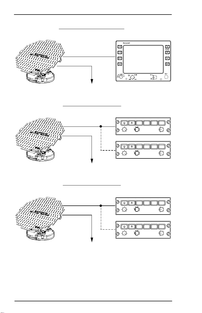
2. System Configurations
The PRIMUSâ880 Digital Weather Radar System can be operatedin
many configurations to display weather or ground mapping information
on a radar indicator,electronic flight instrument system (EFIS) display,
multifunctiondisplay(MFD),oronacombinationof these displays. The
various system configurations are summarized in the following
paragraphs and shown in figure 2-1.
NOTE: Other configurations are possible but not illustrated.
The stand-alone configuration consists of two units: receiver
transmitter antenna (RTA), and a dedicated radar indicator. In this
configuration,theradarindicatorcontainsallthecontrols to operatethe
PRIMUSâ880 Digital Weather Radar System. A single or dual
HoneywellEFIScanbe addedtothestand-aloneconfiguration.Insuch
a case the electronic horizontal situation indicator (EHSI) repeats the
data displayed on the radar indicator. System control remains with
the radar indicator.
The second system configuration uses an RTA, and single or dual
controllers. The single or dual EFIS is the radar display. Since there is
no radar indicator in this configuration, the radar system operating
controlsarelocatedonthecontroller. Withasinglecontroller,all cockpit
radar displays are identical.
The dual configuration gives the appearance of having two radar
systems on the aircraft. In the dual configuration, the pilot and copilot
each select independent radar mode, range, tilt, and gain settings for
display on their respective display. The dual configuration time shares
theRTA.Ontheright-to-leftantenna scan, thesystemswitchestothe
mode, range, tilt, and gain selected by the left controller and updates
the left display. On the reverse antenna scan, the system switches to
the mode, range, tilt, and gain setting selected by the right controller
and updates the right display. Either controller can be slaved to the
other controller to show identical images on both sides of the cockpit.
NOTE: When WAIT, SECTOR SCAN, or FORCED STANDBY are
activated, the radar operates as if in single controller
configuration. This is an exception to the ability of each pilot
to independently select modes.
A28-1146-102-00
System Configurations
2-1
Page 12
PRIMUS
r
880
Digital
W
eather
Radar
System
RTA
WU-880
RTA
WU-880
STAND-ALONE CONFIGURATION
SINGLE OR DUAL EFIS OPTION
EFIS ONLY CONFIGURATION
CONTROLLER
PULL
VAR
MAXMIN
PULL
VAR
MAXMIN
SINGLE OR DUAL EFIS
2ND CONTROLLER
INDICATOR
WI-880
WC-880
STAB
TRB
RCTWX
SBY GMAP
FP
OFF
TST
STAB
TRB
RCTWX
SBY GMAP
FP
OFF
TST
OPTIONAL
TGT SECT
+
PULL
ACT
-
TILTSLVRADARGAIN
TGT SECT
+
PULL
ACT
-
TILTSLVRADARGAIN
System Configurations
2-2
RTA
WU-880
EFIS / MFD CONFIGURATION
MFD AND
2ND CONTROLLER
SINGLE OR DUAL EFIS
PRIMUSâ880 Configurations
Figure 2-1
CONTROLLER
WC-880
STAB
TRB
RCTWX
PULL
SBY GMAP
VAR
FP
OFF
TST
MAXMIN
STAB
TRB
RCTWX
PULL
SBY GMAP
VAR
FP
OFF
TST
MAXMIN
OPTIONAL
AD-46690-R2@
A28-1146-102-00
TGT SECT
+
PULL
ACT
-
TILTSLVRADARGAIN
TGT SECT
+
PULL
ACT
-
TILTSLVRADARGAIN
Page 13

PRIMUS
r
880
Digital
W
eather
Radar
System
The third system configuration is similar to the second except that a
Honeywell multifunction display (MFD) system is added. As before,
single or dual controllers can beused. When a singlecontroller is used,
all displays show the same radar data. Dual controllers are used to
operate in the dual mode. The MFD can be slaved to either controller
toduplicatethedata displayedontheselectedside.Table2-1isatruth
table for dual control modes.
Left
Controller
Mode
Right
Controller
Mode
Left Side
(NOTE 1)
Right Side
(NOTE 1)
RTA
Mode
OFF OFF OFF OFF OFF
OFF Standby ”SLV”
Standby Standby
Standby
Standby OFF Standby ”SLV”
Standby
Standby
OFF ON ”SLV” ON ON ON
ON OFF ON ”SLV” ON ON
Standby ON Standby/
ON/2 ON
2
ON Standby ON/2 Standby/2 ON
ON ON ON/2 ON/2 ON
Standby Standby Standby Standby Standby
Dual Control Mode Truth Table
Table 2-1
A28-1146-102-00
System Configurations
2-3
Page 14
PRIMUSr880 Digital Weather Radar System
NOTES: 1. ON is used to indicate any selected radar mode.
2. “SLV” means that displayed data is controlled by
opposite side controller.
3. XXX/2 means that display is controlled by appropriate
on--side control for the antenna sweep direction
associated with that control. (/2 implies two controllers
are on.)
4. In standby, the RTA is centered in azimuth with 15_
upward tilt. Video data is suppressed. The transmitter
is inhibited.
5. The MFD, if used, can repeat either left-- or right--side
data, depending upon external switch selection.
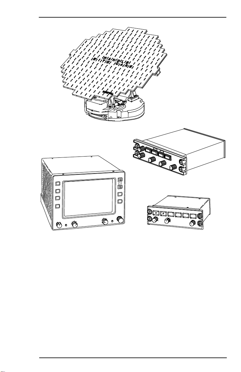
Equipment covered in this guide is listed in table 2--2 and shown in
figure 2--2.
Model Unit Part No.
Cockpit Mounted Options
WI--880 Weather Radar Indicator 7007700--401/402/
403/404
WC--880 Weather Radar Controller 7008471--4XX
WC--884 Weather Radar Controller 7006921--815/816
Remote Mounted Equipment
WU--880 Receiver Transmitter Antenna 7021450--801
NOTE: Typically, either the indicator or one of the remote
controllers (one or two) is installed.
PRIMUSR880 Weather Radar Equipment List
Tab l e 2- -2
System Configurations
2-4
A28--1146-- 102-- 03
REV 3
Page 15
PRIMUS
r
880
Digital
W
eather
Radar
System
WU-880 RT A
WC-884 CONTROLLER
Typical PRIMUSâ880 Weather Radar Components
A28-1146-102-00
Figure 2-2
WC-880 CONTROLLERWI-880INDICATOR
System Configurations
AD-46691@
2-5/(2-6 blank)
Page 16
PRIMUS
r
880
Digital
W
eather
Radar
System
3. Operating Controls
WI-880 WEATHER RADAR INDICATOR OPERA TION
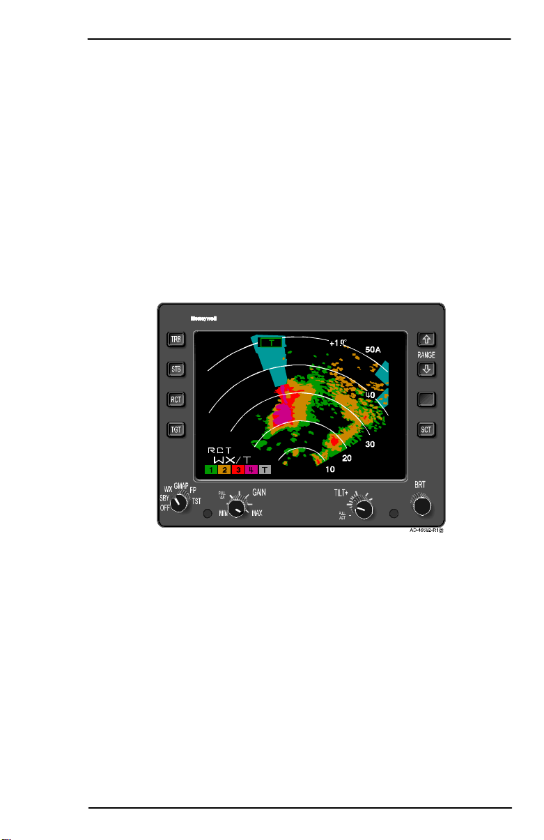
Allcontrolsusedtooperate the system displayshown in figure 3-1,are
located on the WI-880Weather Radar Indicator front panel. There are
three basic controllers that are described in this section, they are (in
order of description):
D WI-880 Weather Radar Indicator
D WC-880 Weather Radar Controller
D WC-884 Weather Radar Controller.
AUTO
TILT
21 3 4
T
10
+1.0
50
40
30
20
AZ
Typical PRIMUSâ880 Digital
Weather Radar Display
Figure 3-1
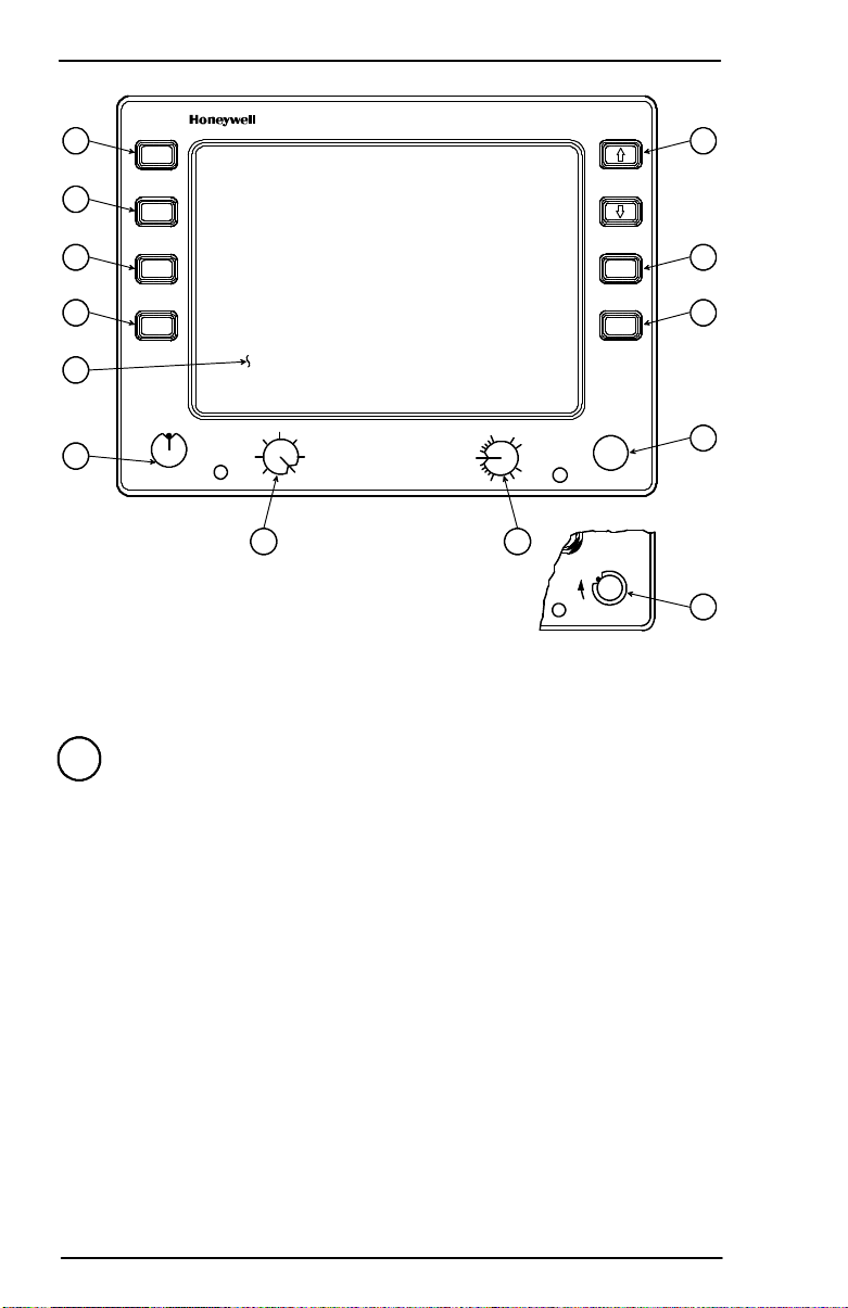
The controls and display features of the WI-880 Weather Radar
Indicator are indexed and identified in figure 3-2. Brightness levels for
all legends and controls on the indicator are controlled by the dimming
bus for the aircraft panel.
A28-1146-102-00
Operating Controls
3-1
Page 17
PRIMUS
r
880
Digital
W
eather
Radar
System
6
5
TRB
RANGE
STB
7
4
3
RCT
TGT
AZ
SCT
8
9
1
GMAP
WX FP
SBY
TST
OFF
2
PULL
VAR
MIN
12
GAIN
MAX
TILT
PULL
ACT
+
-
11
OFF
BRT
BRT
SBY
LX
CLR
TST
AD-46693-R1@
10
10
WI-880 Weather Radar Indicator Front Panel View
Figure 3-2
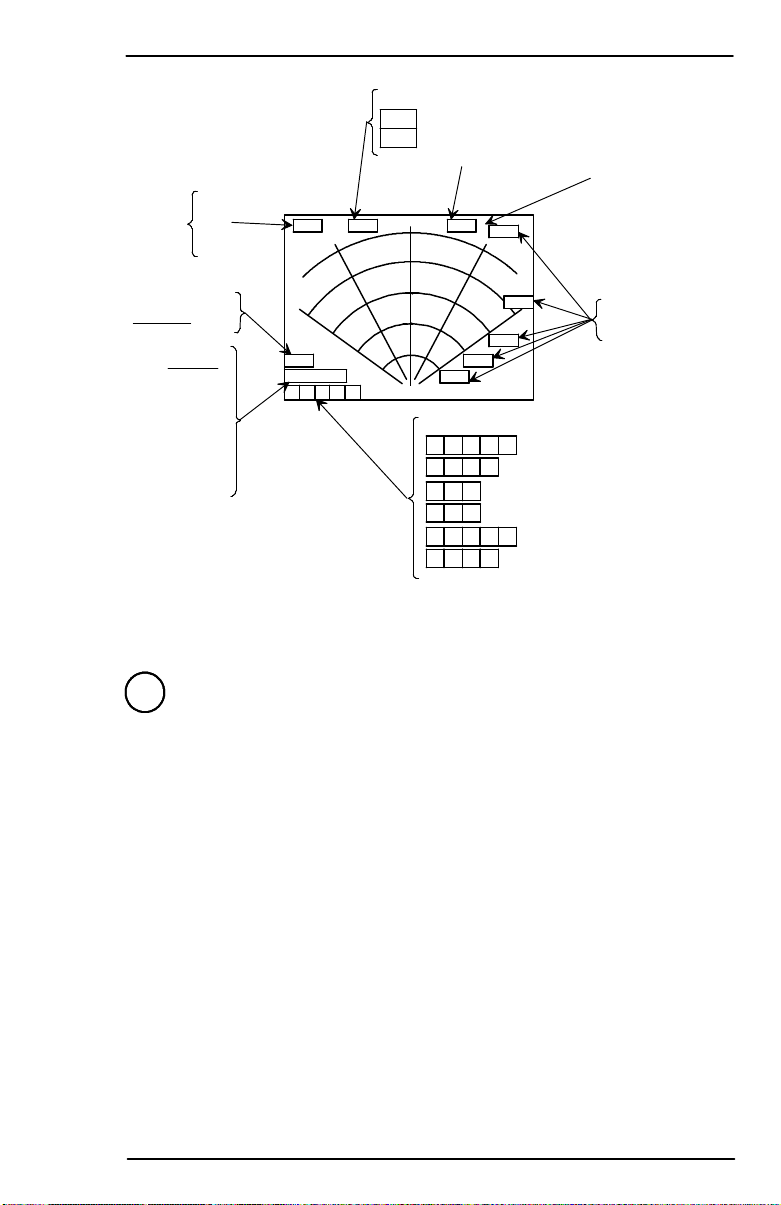
1 Display Area
Seefigure3-3andtheassociatedtext whichexplainsthealphanumeric
display.
Operating Controls
3-2
A28-1146-102-00
Page 18
PRIMUS
r
880
Digital
W
eather
Radar
System
NOTE
FAIL
STB
TARGET/TARGET ALERT:
ARM (GREEN)
T
ALERT (YELLOW INVERTED VIDEO)
TGT
TILT ANGLE
A
ALTITUDE
COMPENSATED
TILT (ACT)
ANNUNCIATION
REACT: RCT
MODE:
STBY
FSBY
WAIT
TEST
WX
WX/T
FLTPLN
GMAP
MESSAGES ARE LISTED
NOTE:
IN PRIORITY ORDER.
COLOR BAR:
1 2 3 4 T
V A R !
1 2 3
GMAP CALIBRATED GAIN
GMAP VARIABLE GAIN
V A R
1 2 3 4 T
V A R !
WX CALIBRATED GAIN
WX VARIABLE GAIN
WX/T CALIBRATED GAIN
WX/T VAR
RANGE RING
MARKERS
(120-DEGREE
SCAN SHOWN)
AD-46694-R2@
WI-880 Weather Radar Indicator Display Screen Features
Figure 3-3
2 Function Switch
A rotary switch used to select the following functions:
D OFF- This position turns off the radar system.
D SBY (Standby) - Thisposition places the radar system in standby ,
a ready state, with the antenna scan stopped, the transmitter
inhibited, and the display memory erased. STBY, in white, is shown
in the mode field.
If SBY is selected before the initial RTA warmup period is complete
(approximately 90 seconds), the white WAIT legend is shown in
the mode field. When warmup is complete the system changes the
mode field to STBY.
D WX (Weather) - This position selects the WX mode of operation.
When WX is selected, the system is fully operationaland all internal
parameters are set for enroute weather detection. The
alphanumerics are white and WX is shown in the mode field.
A28-1146-102-00
Operating Controls
3-3
Page 19

PRIMUS
r
880
Digital
W
eather
Radar
System
If WX is selected before the initial RTA warmup period is over
(approximately 90 seconds), the white WAIT legend is displayed
in the mode field. In wait mode, the transmitter and antenna scan
are inhibited and the display memory is erased. When the warmup
is complete, the system automatically switches to the WX mode.
The system, in preset gain, is calibrated as listed in table 4-1.
Rainfall Rate
Color
in/hr mm/hr
.04-.16 1-4 Green
.16-.47 4-12 Yellow
.47-2 12-50 Red
> 2 >5 0 Magenta
Rainfall Rate Color Coding
Table 3-1
D GMAP (Ground Mapping) - The GMAP position puts the radar
system in the ground mapping mode. The system is fully
operational and all parameters are set to enhance returns from
ground targets.
NOTE: R EACT, TGT,orTURBmodes are notselectable in GMAP.
WARNING
WEATHER TYPE TARGETS ARE NOT CALIBRATED WHEN
THE RADAR IS IN THE GMAP MODE. BECAUSE OF THIS, DO
NOT USE THE GMAP MODE FOR WEATHER DETECTION.
As a constant reminder that GMAP is selected, the alphanumerics
are changed to green, the GMAP legend is shown in the modefield,
and the color scheme is changed to cyan, yellow, and magenta.
Cyan represents the least reflective return, yellow is a moderate
return, and magenta is a strong return.
If GMAP is selected before the initial RTA warmup period is
complete, the white WAIT legend is shown inthe mode field. In wait
mode, the transmitter and antenna scan are inhibited and the
memory is erased. When the warmup period is complete, the
system automatically switches to the GMAP mode.
D FP(FlightPlan)-TheFPpositionputs theradarsystemintheflight
plan mode, which clears the screen of radar data so ancillary data
can be displayed. Examples of this data are:
Operating Controls
3-4
A28-1146-102-00
Page 20

PRIMUSr880 Digital Weather Radar System
D FP (Flight Plan) -- The FP position puts the radar system in the flight
plan mode, which clears the screen of radar data so ancillary data
can be displayed. Examples of this data are:
— Navigation displays
— Electrical discharge (lightning) data.
NOTE: In the FP mode, the radar RTA is put in standby, the
alphanumerics are changed to cyan, and the FLTPLN
legend is shown in the mode field.
The target (TGT) alert mode can be used in the FP mode. With
target alert on and the FP mode selected, the target alert armed
annunciation (green TGT) is displayed. The RTA searches for a
hazardous target from 5 to 55 miles and ±7.5° of the aircraft heading.
No radar targets are displayed. If a hazardous target is detected,
the target alert armed annunciation switches to the alert
annunciation (yellow TGT). This advises the pilot that a hazardous
target is in his flightpath and the WX mode should be selected to
view it.
NOTE: The TGT function is inoperative when a checklist is
displayed.
D TST (Test) -- The TST position selects the radar test mode. A
special test pattern is displayed to verify system operation. The
TEST legend is shown in the mode field. Refer to Section 4, Normal
Operations, for a description of the test pattern.
WARNING
UNLESS THE SYSTEM IS IN FORCED STANDBY, THE
TRANSMITTER IS ON AND RADIATING X--BAND
MICROWAVE ENERGY IN TEST MODE. REFER TO SECTION 6,
MAXIMUM PERMISSIBLE EXPOSURE LEVEL (MPEL), AND THE
APPENDIX, FEDERAL AVIATION ADMINISTRATION (FAA)
ADVISORY CIRCULARS, TO PREVENT POSSIBLE HUMAN BODY
DAMAGE.
FSBY (Forced Standby)
FSBY is an automatic, nonselectable radar mode. As an installation
option, the indicator can be wired to the weight--on--wheels (WOW)
squat switch. When wired, the RTA is in the FSBY mode when the
aircraft is on the ground. In FSBY mode, the transmitter and antenna
scan are both inhibited, the display memory is erased, and the FSBY
legend is displayed in the mode field. When in the FSBY mode,
pushing the STAB button 4 times within 3 seconds, restores normal
operation.
A28--1146-- 102-- 03
REV 3
Operating Controls
3-5
Page 21

PRIMUS
r
880
Digital
W
eather
Radar
System
WARNING
FOR CEDSTANDBYMOD EMUSTBEVERIFIEDBYTHEOPERATOR
TO ENSUR E SAFETY FOR GROUND PERSONNEL.
3 TGT (Target)
The TGT button is an alternate-action switch that enables and
disablestheradartargetalertfeature.Targetalertisselectableinallbut
the 300-mile range. When selected, target alert monitors beyond the
selectedrangeand7.5° on each sideof theaircraftheading.Ifareturn
with target alert characteristics is detected in the monitored area, the
target alert legend changes from the green T armed condition to the
yellow TGT warning condition. (See the target alert characteristics in
table3-2foratargetdescription.)These annunciations advise thepilot
of potentially hazardous targets directly in front of the aircraft that are
outsidetheselectedrange.Whenayellowwarningisreceived,thepilot
should select longer ranges to view the questionable target. (Note that
target alert is inactive within the selected range.)
Selecting target alert forces the system to preset gain. Target alert can
be selected only in the WX or FP modes.
NOTE: In order to activate the target alert warning, the target must
have the depth and range characteristics described in table
3-2.
Operating Controls
3-6
A28-1146-102-00
Page 22

PRIMUS
r
880
Digital
W
eather
Radar
System
Selected Range
(NM)
Minimum Target
Depth (NM)
Target Range
(NM)
5 5 5-55
10 5 10-60
25 5 25-75
50 5 50-100
100 5 100-150
200 5 200-250
300 N/A N/A
FP (Flight Plan) 5 5-55
Target Alert Characteristics
Table 3-2
4 RCT (Rain Echo Attenuation Compensation Technique
(REACT))
The RCT switch is an alternate-action switch that enables and
disables REACT.
The REACT circuitry compensates for attenuation of the radarsignal
as it passes through rainfall. The cyan field indicates areas where
further compensation is not possible. Any target detected within
the cyan field cannot be calibrated and should be considered
dangerous. All targets in the cyan field are displayed as fourth level
precipitation, magenta.
REACT is available in the WX mode only and selecting REACT forces
the system to preset gain. When engaged, the white RCT legend is
displayed in the REACT field.
NOTES: 1. REACT’S three main functions (attenuation
compensation, cyan field, and forcing targets to
magenta)areswitchedonandoffwiththeRCTswitch.
2. Refer to Section 5, Radar Facts, for a description of
REACT.
5 STB (Stabilization)
TheSTBbuttontoggles pitchandrollstabilizationONandOFF.It isalso
used with the STB adjust mode and to override forced standby.
The radar antenna is normally attitude stabilized. It automatically
compensates for roll and pitch maneuvers (refer to Section 5, Radar
Facts, for a description of stabilization). The STB OFF annunciator is
displayed on the screen.
A28-1146-102-00
Operating Controls
3-7
Page 23
PRIMUSr880 Digital Weather Radar System
The radar antenna is normally attitude stabilized. It automatically
compensates for roll and pitch maneuvers (refer to Section 5, Radar
Facts, for a description of stabilization). The STB OFF annunciator is
displayed on the screen.
6 TRB (Turbulence)
The TRB switch is used to select the turbulence detection mode of
operation. The TRB mode can only be selected if the FUNCTION
switch is in the WX position and the selected range is 50 miles or less.
The weather/turbulence mode is annunciated in the mode field with the
WX/T legend. Areas of moderate or greater turbulence are shown in
soft white. The turbulence threshold is five meters per second.
WARNINGS
1. TURBULENCE CAN ONLY BE DETECTED WITHIN AREAS OF
RAINFALL. THE PRIMUS
R
880 DIGITAL WEATHER RADAR
SYSTEM CANNOT DETECT CLEAR AIR TURBULENCE.
2. UNDETECTED TURBULENCE CAN EXIST WITHIN ANY
STORM CELL. REFER TO SECTION 5, RADAR FACTS, OF THIS
GUIDE FOR ADDITIONAL INFORMATION.
Selecting the 100--, 200--, or 300--mile range turns off turbulence
detection. The /T is deleted from the mode annunciation. Subsequently
selecting ranges of 50 miles or less re--engages turbulence detection.
A description of the turbulence detection capabilities and limitations is
given in Section 5 , Radar Facts, of this guide.
7 RANGE
The RANGE buttons are two momentary--contact buttons used to
select the operating range of the radar. The range selections are from
5 to 300 NM full scale. In FP mode, additional ranges of 500 and 1000
NM are available. The up arrow selects increasing ranges, and the
down arrow selects decreasing ranges. Each of the five range rings on
the display has an associated marker that annunciates its range.
8 AZ (Azimuth)
The AZ button is an alternate--action switch that enables and disables
the electronic azimuth marks. When enabled, azimuth marks at 30_
intervals are displayed. The azimuth marks are the same color as the
other alphanumerics.
9 SCT (Scan Sector)
Operating Controls
3-8
A28--1146-- 102-- 03
REV 3
Page 24

PRIMUS
r
880
Digital
W
eather
Radar
System
10 BRT (Brightness) or BRT/LSS (Lightning Sensor System)
The BRT knob is a single-turncontrolthatadjusts the brightness ofthe
display. Clockwise (cw) rotation increases display brightness and
counterclockwise (ccw) rotation decreases brightness.
An optional BRT/LSS four-position rotary switch selects theseparate
LSZ-850 Lightning Sensor System (LSS) operating modes and the
brightnesscontrolonsomemodels.ItsLSS controlswitchpositionsare
as follows:
D OFF - This position removes all power from the LSS.
D SBY (Standby) - This position inhibits the display of LSS data, but
the system accumulates data in this mode.
D LX (Lightning Sensor System) - In this position the LSS is fully
operational and data is being displayed on the indicator.
D CLR/TST(Clear/Test)-Inthis positionaccumulateddataiscleared
from the memory of the LSS. After 3 seconds the test mode is
initiated in the LSS. Refer to the LSZ-850Lightning Sensor System
Pilot’s Handbook, for a detailed description of LSS operation.
11 TILT
The TILT knob is a rotary control that is used to select the tilt angle of
the antenna beam with relation to the horizon. CW rotation tilts beam
upward to +15_; ccw rotation tilts beam downward to -15_.
A digital readout of the antenna tilt angle is displayed on the CRT, with
0.5_ resolution.
D PULL ACT (Altitude Compensated Tilt) Function - When the
TILT control knob is pulled out, the system engages the ACT. In ACT
the antenna tilt is automatically adjusted with regard to the selected
range and barometric altitude. The antenna tilt automatically
readjusts with changes in altitude and/or selected range. In ACT, the
tilt control can fine tune the autotilt setting by ±2°.
ACT is annunciated with an A following the digital tilt readout. The
digital tilt readout always shows the commanded tilt of the antenna
regardless of the tilt command source (ACT command or manual tilt
command).
WARNINGS
1. TO AVOID FLYING UNDER OR OVER STORMS,
FREQUENTLY SELECT MANUAL TILT TO SCAN BOTH
ABOVE AND BELOW YOUR FLIGHT LEVEL.
2. ALWAYS USE MANUAL TILT FOR WEATHER ANALYSIS.
A28-1146-102-00
Operating Controls
3-9
Page 25

PRIMUS
r
880
Digital
W
eather
Radar
System
12 GAIN
The GAIN knob is a single-turn rotary control and push/pull switch that
is used to control the receivergain. Push in onthe GAIN switch to enter
the system into the preset calibrated gain mode. Calibrated gain is the
normalmodeandis used forweatheravoidance.Incalibratedgain,the
rotary portion of the GAIN control does nothing. In calibrated gain, the
colorbarlegendis labeled1,2,3,4inWXmode or 1,2,3inGMAPmode.
Pull out on the GAIN switch to enter the system into the variable gain
mode with VAR displayed in the color bar. Variable gain is useful for
additional weather analysis and for ground mapping. In WX mode,
variable gain can increase receiver sensitivity over the calibrated level
to show very weak targets or it can be reduced below the calibrated
level to eliminate weak returns.
WARNING
HAZARDOUS TARGETS MAY BE ELIMINATED FROM THE DISPLAY WITH LOW SETTINGS OF VARIABLE GAIN.
In the GMAP mode, variable gain is used to reduce the level of the
typically very strong returns from ground targets.
Minimum gain is with the control at its full ccw position. Gain increases
as the control is rotated cw from full ccw . At full cw position, the gain
is at maximum.
In variable gain, the color bar legendcontains the variable gain (VAR)
annunciation. Selecting RCT or TGT forces the system into calibrated
gain.
Operating Controls
3-10
A28-1146-102-00
Page 26
PRIMUS
r
880
Digital
W
eather
Radar
System
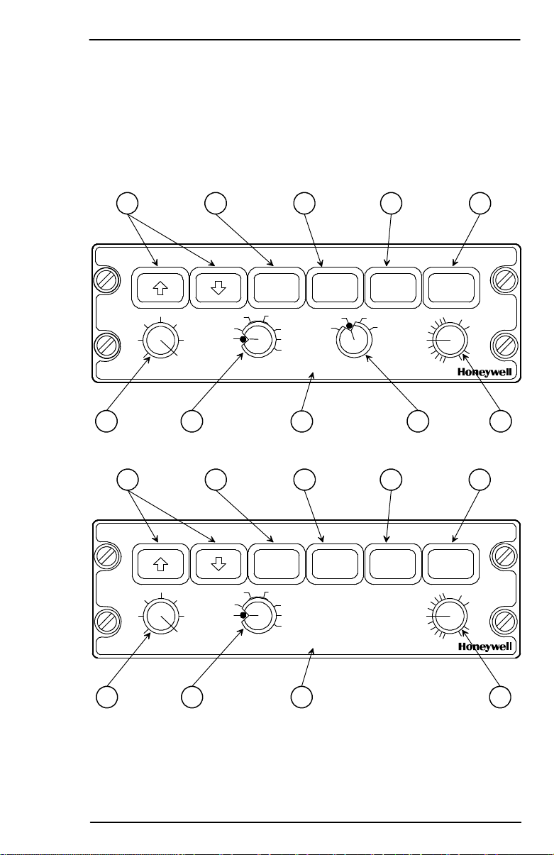
WC-880 WEATHER RADAR CONTROLLER OPERATION
The controls and display features of the WC-880 Weather Radar
Controller are indexed andidentified in figure 3-4.Brightness levelsfor
all legend and controls on the indicator are controlled by the dimming
bus for the aircraft panel.
7 6 5 4 3
OFF
TRB STAB TGT SECT
MAXMIN
PULL
VAR
SBY GMAP
OFF
RCTWX
FP
TST
RADARGAIN
SLV
OFF
LSS
LXSBY
CLR
TST
PULL
ACT
TILT
+
-
8 1 9 10 2
AD-46695-R1@
7 6 5 4 3
OFF
TRB STAB TGT SECT
MAXMIN
PULL
VAR
SBY GMAP
OFF
RCTWX
FP
TST
SLVRADARGAIN
PULL
ACT
TILT
+
-
8 1 9 2
AD-46696-R1@
WC-880 Weather Radar Controller Configurations
A28-1146-102-00
Figure 3-4 (cont)
Operating Controls
3-11
Page 27
PRIMUS
r
880
Digital
W
eather
Radar
System
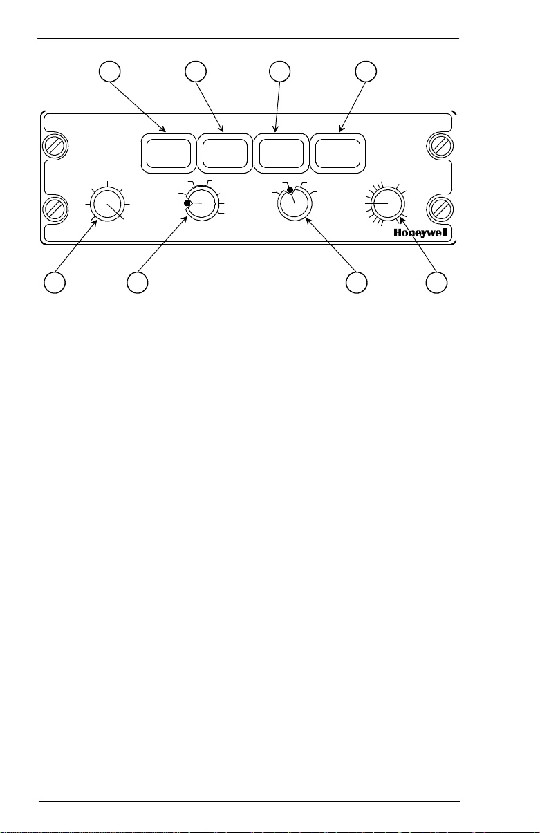
6 5 4 3
TRB STAB TGT SECT
MAXMIN
PULL
VAR
SBY GMAP
OFF
RCTWX
FP
TST
OFF
LXSBY
CLR
TST
LSSSLVRADARGAIN
PULL
ACT
TILT
+
-
8 1 10 2
AD-46697-R1@
WC-880 Weather Radar Controller Configurations
Figure 3-4
NOTES: 1. With a controller without built-inrange control, range
iscontrolled from the installed EFIS navigationdisplay
2. Controllers are available with and without the LSS
function.
3. Whenever single or dual radar controllers are used,
theradardataisdisplayedontheEFIS and/or an MFD
or navigation display (ND).
Operating Controls
3-12
A28-1146-102-00
Page 28
PRIMUS
r
880
Digital
W
eather
Radar
System
1 RADAR
This rotary switch is used to select one of the following functions.
D OFF - This position turns the radar system off.
D SBY (Standby) -Thisposition places the radar system in standby;
a ready state, with the antenna scan stopped, the transmitter
inhibited, and the display memory erased. STBY isdisplayed on the
EFIS/MFD.
D WX (Weather) - Thisposition selects the weather detectionmode.
The system is fully operational and all internal parameters are set
for enroute weather detection.
If WX is selected before the initial RTA warmup period is complete
(approximately 45 to 90 seconds), the WAIT legend is displayed on
the EFIS/MFD. In WAITmode, the transmitter and antenna scan are
inhibited and the display memory is erased. When the warmup is
complete, the system automatically switches to the WX mode.
The system, in preset gain, is calibrated as described in table 3-3.
Rainfall Rate
Color
in/hr mm/hr
.04-.16 1-4 Green
.16-.47 4-12 Yellow
.47-2 12-50 Red
> 2 >5 0 Magenta
Rainfall Rate Color Coding
Table 3-3
D RCT (Rain Echo Attenuation Compensation Technique) - This
switch position turns on RCT.
The REACT circuitry compensates for attenuation of the radar
signal as it passes through rainfall. The cyan field indicates areas
where further compensation is not possible. Any target detected
within the cyan field cannot be calibrated and should be considered
dangerous. All targets in the cyan field are displayed as 4th level
precipitation, magenta.
RCT is a submode of the WX mode and selecting RCT forces the
sys tem to preset gain. When RCT is selected, the RCT legend is
dis playe d on the EFIS/MFD .
A28-1146-102-00
Operating Controls
3-13
Page 29

PRIMUS
r
880
Digital
W
eather
Radar
System
NOTES: 1. REACT’s three functions (attenuation
compensation, cyan field, and forcing targets to
magenta) are switched on and off with the RCT
switch.
2. Refer to Section 5, Radar Facts, for a description
of REACT.
D GMAP (Ground Mapping) - The GMAP position puts the radar
system in the Ground Mapping mode. The system is fully
operational and all parameters are set to enhance returns from
ground targets.
NOTE: REACT, TGT, or TRB modes are not selectable in GMAP.
WARNING
WEATHER TYPE TARGETS ARE NOT CALIBRATED WH EN
THE RADAR ISINTHE GMA PMODE.BECAUSE OFTHIS, DON OT
USE THE GMAP MODE FOR WEATHER DETEC TION.
As a constant reminder that GMAP is selected, the alphanumerics
are changed to green, the GMAP legend is displayed in the
mode field, and the color scheme is changed to cyan, yellow, and
magenta. Cyan represents the least reflective return, yellow is a
moderate return, and magenta is a strong return.
If GMAP is selected before the initial RTA warmup period is
complete (approximately 45 to 90 seconds), the white WAIT legend
is displayed in the mode field. In wait mode, the transmitter and
antenna scan are inhibited and the memory is erased. When the
warmup period is complete, the system automatically switches to
the GMAP mode.
D FP(FlightPlan)-TheFPpositionputs theradarsystemintheflight
plan mode, which clears the screen of radar data so ancillary data
can be displayed. Examples of this data are:
- Navigation displays
- Electrical discharge (lightning) data.
NOTE: In the FP mode, the radar RTA is put in standby, the
alphanumeric s are changed to cyan , and the FLTPLN
legend is displayed in the mode field.
Operating Controls
3-14
A28-1146-102-00
Page 30

PRIMUS
r
880
Digital
W
eather
Radar
System
The target alert mode can be used in the FP mode. With target alert
on and the FP mode selected , the target alert armed annunciation
(gr een TGT) is displayed. The RTA s earches for a hazardous target
from 5 to 55 miles and ±7.5 degr ees of dead ahead. No radar
tar gets are displayed. If a hazardous target is detected, the targetalert
armed annunciation switc hes to the alert annunciation (amber TGT).
This advises thepilot that a hazardous targ et is in hisflightpath and he
should select the WX mode to view it.
NOTE: When displaying checklist,the TGT func tion is inoperativ e.
D TST (Test) - The TST position selects the radar test mode. A
special test pattern is displayed to verify system operation. The
TEST legend is displayed in the mode field. Refer to Section 4,
Normal Operations, for a description of the test pattern.
WARNING
UNLESS THE SYSTEM IS IN FORCED STANDBY, THE TRANSMITTER IS ON AND RADIATING X-BAND MICROWAVE ENERGY IN
TEST MODE. REFER TO SECTION 6, MAXIMUM PERMISSIBLE
EXPOSURE LEVEL (MPEL).
D FSBY (Forced Standby) - FSBY is an automatic, nonselectable
radar mode. As an installation option, the indicator can be wired
to the weight-on-wheels (WOW) squat switch. When wired, the
RTA is in the FSBY modewhen the aircraft is on the ground. In FSBY
mode, the transmitter and antenna scan are both inhibited, the
display memory is erased, and the FSBY legend is displayed in the
mode field. When in the FSBY mode, pushing the STAB button 4
times in 3 seconds restores normal operation.
The FSBY mode is a s afety feature that inhibits the transmitter on the
ground to eliminate the X-Band microwave radiation hazard. Refer to
Sec tion 6, Max imum Permissible Exp osure Level (MPEL).
WARNING
FORCED STANDBY MODE MUST BE VERIFIED BY THE OPERATOR TO ENSURE SAFETY FOR GROUND PERSONNEL.
In installationswith tworadar controllers, it is onlynecessarytooverrid e
for ced standby from one controller.
If either controller is returned to standby mode while weight is on
wheels, the system returns to the forced standby mode.
A28-1146-102-00
Operating Controls
3-15
Page 31

PRIMUS
r
880
Digital
W
eather
Radar
System
2 TILT
The TILT switch is a rotary control that is used to select the tilt angle of
antenna beam with relation to the horizon. CW rotation tilts beam
upward 0_ to 15_; ccw rotation tilts beam downward 0_ to -15_. The
range between +5_ and -5_ is expanded forease of setting. Adigital
readout of the antenna tilt angle is displayed on the EFIS.
D PULL ACT (Altitude Compensated Tilt) Function - When the
TILT control knob is pulled out, the system engages the ACT
(option). In ACT , the antenna tilt is automatically adjusted with
regard to the selected range and barometric altitude. The antenna
tilt automatically readjusts with changes in altitude and/or selected
range. In ACT, the tilt control can fine tune the tilt setting by ±2°.
ACT is annunciated with an A following the digital tilt readout. The
digital tilt readout always shows the commanded tilt of the antenna
regardless of the tilt command source (ACT command or manual tilt
command).
WARNINGS
1. TO AVOID FLYING UNDER OR OVER STORMS,
FREQUENTLY SELECT MANUAL TILT TO SCAN BOTH
ABOVE AND BELOW YOUR FLIGHT LEVEL.
2. ALWAYS USE MANUAL TILT FOR WEATHER ANALYSIS.
3 SECT (Scan Sector)
The SECT switch is an alternate-action button that is used to select
either the normal 12 looks/minute 120_ scan or the faster update 24
looks/minute 60_ sector scan.
4 TGT (Target)
The TGT switch is an alternate-action, button that enables and
disablestheradartargetalertfeature.Targetalertisselectableinallbut
the 300 mile range. When selected, target alert monitors beyond the
selected range and 7.5_ on each side of theaircraft heading. If a return
withcertaincharacteristics is detected in themonitoredarea, the target
alert changes from the green armed condition to the yellow TGT
warning condition. This annunciation advises the pilot that a potentially
hazardoustargetliesdirectlyin front and outsideof theselected range.
When this warning is received, the pilot should select longer ranges to
view the questionable target. Note that target alert isinactive within the
selected range.
Operating Controls
3-16
A28-1146-102-00
Page 32

PRIMUS
r
880
Digital
W
eather
Radar
System
Selecting target alert forces the system to preset gain. Target alert can
only be selected in the WX and FP modes.
In order to activate target alert, the target must have the depth and
range characteristics described in table 3-4:
Selected Range
(NM)
Minimum Target
Depth (NM)
Target Range
(NM)
5 5 5-55
10 5 10-60
25 5 25-75
50 5 50-100
100 5 100-150
200 5 200-250
300 N/A N/A
FP (Flight Plan) 5 5-55
WC-880 Controller Target Alert Characteristics
Table 3-4
5 STB (Stabilization)
The STB button turns the pitch and roll stability ON and OFF. It is also
used with the STB adjust mode and to override forced standby.
NOTE: Some controllers annunciate OFF when stabilization is OFF.
6 TRB (Turbulence Detection)
TRB is a switch used to select the turbulence detection mode of
operation. The TRB mode can only be selected if the FUNCTION
switch is in the WX or RCT positions andtheselected range is 50miles
or less. The weather/turbulence mode is annunciated in the mode field
withtheWX/Tlegend.Areasofatleastmoderateturbulenceareshown
in soft white. The turbulence threshold is five meters per second.
A28-1146-102-00
Operating Controls
3-17
Page 33

PRIMUSr880 Digital Weather Radar System
WARNINGS
1. TURBULENCE CAN ONLY BE DETECTED WITHIN AREAS OF
RAINFALL. THE PRIMUS
R
880 DIGITAL WEATHER RADAR
SYSTEM CANNOT DETECT CLEAR AIR TURBULENCE.
2. UNDETECTED TURBULENCE CAN EXIST WITHIN ANY
STORM CELL. REFER TO SECTION 5, RADAR FACTS, OF THIS
GUIDE FOR ADDITIONAL INFORMA TION.
Selecting the 100, 200, or 300 mile range turns off the turbulence
detection. The /T is deleted from the mode annunciation and variable
gain is engaged if previously selected. Subsequent selection of ranges
of 50 miles or less re--engages turbulence detection.
A description of the turbulence detection capabilities and limitations of
this radar system is given in Section 5, Radar Facts, of this guide.
7 RANGE
The RANGE switches are two momentary contact buttons that are used
to select the operating range of the radar (and LSS if installed). The
system permits selection of ranges in WX mode from 5 to 300 NM full
scale. In the flight plan (FPLN) mode, additional ranges of 500 and
1000 miles are permitted. The up arrow selects increasing ranges,
while the down arrow selects decreasing ranges. One--half the
selected range is annunciated at the one--half scale range mark on the
EHSI.
NOTE: Some Integrated avionics systems incorporate radar range
with the map display range control on a MFD/ND display.
8GAIN
The GAIN is a single turn rotary control and push/pull switch that is used
to control the receiver gain. When the GAIN switch is pushed, the
system enters the preset, calibrated gain mode. Calibrated gain is the
normal mode and is used for weather avoidance. In calibrated gain, the
rotary portion of the GAIN control does nothing.
When the GAIN switch is pulled out, the system enters the variable
gain mode. Variable gain is useful for additional weather analysis and
for ground mapping. In WX mode, variable gain can increase receiver
sensitivity over the calibrated level to show weak targets or it can
be reduced below the calibrated level to eliminate weak returns.
Operating Controls
3-18
A28--1146-- 102-- 03
REV 3
Page 34

PRIMUS
r
880
Digital
W
eather
Radar
System
WARNING
LOW VARIABLE GAIN SETTINGS CAN ELIMINATE HAZARDOUS
TARGETS FROM THE DISPLAY.
In GMAP mode, variable gain is used to reduce the level of strong
returns from ground targets.
Minimum gain is attained with the control at its full ccw position. Gain
increases as the control is rotated in a cw direction from full ccw at full
cw position, the gain is at maximum.
The VAR! legend annunciates variable gain. Selecting RCT or TGT
forces the system into calibrated gain.
9 SLV (Slave)
The SLV annunciator is only used in dual controller installations. With
dual controllers, one controller can be slaved to the other byselecting
OFF on that controller only, with the RADAR mode switch. This slaved
condition is annunciated with the SLV annunciator.
In the slaved condition, both controllers must be off before the
radar system turns off.
10 LSS (Lightning Sensor System) (Option)
The LSS switch is an optional four-position rotary switch that selects
the LSS operating modes described below:
D OFF - In this position all power is removed from the LSS.
D SBY-Inthis positionthedisplayofLSS dataisinhibited,buttheLSS
still accumulates data.
D LX -In this position the LSS is fully operational and it displays LSS
data on the indicator.
D CLR/TST -In this position, accumulated data is cleared from the
memory of the LSS. After 3 seconds the test mode is initiated in the
LSS.
A28-1146-102-00
Operating Controls
3-19
Page 35

PRIMUS
r
880
Digital
W
eather
Radar
System
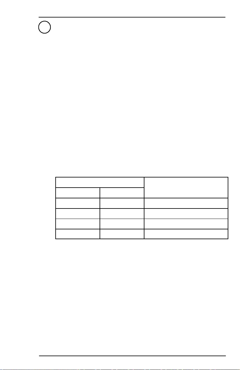
WC-884 WEATHER RADAR CONTROLLER OPERATION
The controls and display features of the WC-884 Weather Radar
Controller are indexed andidentified in figure 3-5.Brightness levelsfor
all legend and controls on the indicator are controlled by the dimming
bus for the aircraft panel.
Whenever single or dual radar controllers are used, the radar data is
displayed on the EFIS, MFD, or NAV display.
1 2 3 4 5
BRT
TGT TRBRCTSTAB
PULL VAR
GAIN
TEST
STBY
OFF
MAXMIN
MODE
WX
GMAP
SLV
50
25
10
RANGE
10 9 8 7 6
100
200
300
FPLN
PULL ACT
0
TILT
+
-
AD-46698-R2@
WC-884 Weather Radar Controller
Figure 3-5
1 BRT (Brightness)
The BRT switch is a rotary control that is used to set the radar (raster)
brightness on the EFIS display.
2 TGT (Target Alert)
The TGT switch is an alternate-action, button that enables and
disablestheradartargetalertfeature.Targetalertisselectableinallbut
the 300-mile range. When selected, target alert monitors beyond the
selected range and 7.5_ on each side of theaircraft heading. If a return
withcertaincharacteristics is detected in themonitoredarea, the target
alert changes from the green armed condition to the amber TGT
warning condition. (Refer to the target alert characteristics in table 3-5
foratargetdescription.)TheamberTGTalertsthepilotastopotentially
hazardous targets directly in front and outside of the selected range.
When the alert is given, the pilot should select longer ranges to view
the questionable target. Target alert is inactive within the selected
range.
Operating Controls
3-20
A28-1146-102-00
Page 36

PRIMUS
r
880
Digital
W
eather
Radar
System
Selecting target alert forces the system into preset gain. Target alert
can be selected in the WX and FP modes.
To activate target alert, the target must have the depth and range
characteristics described in table 3-5:
Selected Range
(NM)
Minimum Target
Depth (NM)
Target Range
(NM)
10 5 10-60
25 5 25-75
50 5 50-100
100 5 100-150
200 5 200-250
300 N/A N/A
FP (Flight Plan) 5 5-55
WC-884 Controller Target Alert Characteristics
Table 3-5
3 STB (Stabilization)
The STAB button is a that turns the pitch and roll stabilization ONand
OFF.
This radar is normally attitude stabilized. It automatically compensates
for roll and pitch maneuvers (refer to Section 5, Radar Facts, for a
description of stabilization). The amber STB annunciator appears
on the screen. Itis alsousedwiththeSTBadjustmode,andtooverride
forced standby.
4 RCT (Rain Echo Attenuation Compensation Technique)
SelectingRCTforcesthe systemtopresetgain.WhenRCTisselected,
the green REACT legend is displayed in the mode field. The RCT
circuitry compensates for attenuation of the radar signal as it passes
through rainfall. The cyan field indicates areas where further
compensationis not possible. Anytargetdetectedwithinthe cyanfield
cannot be calibrated and should be considered dangerous. Alltargets
in the cyan field are displayed as fourth level precipitation, magenta.
NOTE: Refer to Section 5, Radar Facts, for a description of REACT.
A28-1146-102-00
Operating Controls
3-21
Page 37

PRIMUSr880 Digital Weather Radar System
5 TRB (Turbulence Detection)
TRB switch is used to select the turbulence detection mode of
operation. The TRB mode can only be selected if the MODE switch is
in the WX position and the selected range is 50 miles or less. The
weather/turbulence mode is annunciated in the mode field with the
green WX/T legend. Areas of at least moderate turbulence are shown
in soft white.
CAUTION
TURBULENCE CAN ONLY BE DETECTED WITHIN AREAS OF
RAINFALL. THE PRIMUS
R
880 DIGITAL WEATHER RADAR
SYSTEM DOES NOT DETECT CLEAR AIR TURBULENCE.
WARNING
UNDETECTED TURBULENCE CAN EXIST WITHIN ANY STORM
CELL. REFER TO SECTION 5, RADAR FACTS, OF THIS GUIDE
FOR ADDITIONAL INFORMATION.
Selecting the 100--, 200--, or 300--mile range turns off the turbulence
detection. The /T is deleted from the mode annunciation and variable
gain is engaged if previously selected. Subsequent selection of ranges
of 50 miles or less re--engages turbulence detection.
A description of the turbulence detection capabilities and limitations can
be found in Section 5, Radar Facts, of this guide.
6TILT
The TILT switch is a rotary control used to select tilt angle of antenna
beam with relation to the horizon. CW rotation tilts beam upward to
+15_; ccw rotation tilts beam downward to --15_.
A digital readout of the antenna tilt angle is displayed on the EFIS.
D PULL ACT (Altitude Compensated Tilt) Function -- When the
TILT control knob is pulled out, the system engages the ACT
(option). In ACT, the antenna tilt is automatically adjusted with
regard to the selected range and barometric altitude. The antenna
tilt automatically readjusts with changes in altitude and/or selected
range. In ACT, the tilt control can fine tune the tilt setting by ±2°.
ACT is annunciated with an A following the digital tilt legend. The
digital tilt readout always shows the commanded tilt of the antenna
regardless of the tilt command source (ACT command or manual tilt
command).
Operating Controls
3-22
A28--1146-- 102-- 03
REV 3
Page 38

PRIMUS
r
880
Digital
W
eather
Radar
System
WARNINGS
1. TO AVOID FLYING UNDER OR OVER STORMS,
FREQUENTLY SELECT MANUAL TILT TO SCAN BOTH
ABOVE AND BELOW YOUR FLIGHT LEVEL.
2. ALWAYS USE MANUAL TILT FOR WEATHER ANALYSIS.
7 RANGE
RANGE is a rotary control used to select oneof six ranges (10, 25, 50,
100,200,and300 NM).Theseventhpositionofthe rangeswitchisflight
plan mode. Selecting FPLNblanks the radar informationfromthe EFIS
display and the mode annunciation flashes if a radiating mode is
selected. The EFIS is set to a range determined by the installation.
Target alert can be u sed in the FPLN mode. With target alert on in the
FPLNmode,thetarge talertarmedannunciation(greenTGT)isdisplayed.
The RTA bec omes activ e and starts searching for a hazardous ta rget
from 5 to55milesand ±7.5_ deadahead. Noradartargetsaredis played.
If a haza rdous target is detected, the target aler t ar med annunciation
switches to the alert annunciation (amber TGT). This advisory indic ates
that a hazardous target is in the aircraft’s flightpath and the WX mode
should be selected.
8 SLV (Slave)
TheSLVannunciatorisadead frontannunciatorthatis onlyusedindual
controller installations. With dual controllers, one controller can be
slavedtotheotherbyselectingtheRADARmodeswitchtoOFF on that
controller, only. This slaved condition is annunciated with the SLV
annunciator.
In the slaved condition both controllers must be off before the radar
system turns off.
9 MODE
The MODE switch is a rotary switch used to select one of the following
functions:
D OFF - In this position the radar system is turned off.
D STBY - In this position the radar system is placed in standby; a
ready state, with the antenna scan stopped, the transmitter
inhibited, and the display memory erased. STBY, in green, is
displayed in the mode field.
If STBY is selected before the initial RTA warmup period is complete
(approximately 45 - 90 seconds), the flashing WAIT legend is
displayed in the mode field.
A28-1146-102-00
Operating Controls
3-23
Page 39

PRIMUS
r
880
Digital
W
eather
Radar
System
When the warmup is complete, the system changes the mode field
from WAIT to STBY.
D TEST- This position selects the radar test mode. A test pattern is
displayed to verify that system operates. The green TEST legend
is displayed in the mode field. Refer to Section 4, Normal
Operation, for a description of the test pattern.
WARNING
UNLESS THE SYSTEM IS IN FORCED STANDBY, THE TRANSMITTER IS ON AND RADIATING X-BAND MICROWAVE ENERGY IN
TEST MODE. REFER TO SECTION 6, MAXIMUM PERMISSIBLE EXPOSURE LEVEL (MPEL).
D WX - In this position, the radar system is fully operational and all
internal parameters are set for enroute weather detection.
If WX is selected before the initial RTA w armup period is complete, a
flashing WAIT legend is displayed. In WAIT mode, the transmitter
and antenna scan are inhibited and the memory is erased. When the
war mup is complete, the system automatically switc hes to the WX
mode and a green WX is displayed in mode field.
The system, in preset gain, is calibrated given in table NOTAG.
Rainfall Rate
Color
in/hr mm/hr
.04-.16 1-4 Green
.16-.47 4-12 Yellow
.47-2 12-50 Red
> 2 >5 0 Magenta
Rainfall Rate Color Coding
Table 3-6
D GMAP - Selecting GMAP places the radar system in the ground
mapping mode. The system is fully operational and all internal
parameters are set to enhance returns from ground targets. RCT
compensation is inactive.
WARNING
WEATHER TYPE TARGETS ARE NOT CALIBRATED WHEN
THE RADAR IS IN THE GMAP MODE. BECAUSE OF THIS, DO
NOT USE THE GMAP MODE FOR WEATHER DETECTION.
Operating Controls
3-24
A28-1146-102-00
Page 40

PRIMUS
r
880
Digital
W
eather
Radar
System
When GMAP is selected, a green GMAP legend is displayed and the
color scheme is changed to cyan, yellow, magenta. Cyan
represents the least reflective return, yellow is a moderate return,
and magenta is a strong return.
If GMAP is selected before the initial RTA warmup period is
complete, a flashing WAIT legend is displayed. In WAIT mode, the
transmitter and antenna scan are inhibited and the memory is
erased. When the warmup is complete, the system automatically
switches to the GMAP mode.
WARNING
THESYSTEMPERFORMSONLY THE FUNCTIONS OF WEATHER
DETECTION OR GROUND MAPPING. IT CANNOT BE RELIED
UPON FOR PROXIMITY WARNING OR ANTICOLLISION
PROTECTION.
D FSBY - Forced standby is an automatic, nonselectable radar
mode. As an installation option, the controllers can be wired to the
WOW squat switch. When wired, the RTA is in the forced standby
mode when the aircraft is on the ground. In the forced standby
mode, the transmitter and antenna scan are both inhibited, the
memory is erased, and the amber FSBY legend is displayed in the
mode field. When in the forced standby mode, pushing the STAB
button 4 times in 3 seconds, exits the mode.
FSBY mode is a safety feature that inhibits the transmitter on the
ground to eliminate the X-band microwave radiation hazard. Refer
to Section 6, Maximum Permissible Exposure Level (MPEL).
NOTE: In dual installations, overriding the forced standby using
the TGT button is done on only one controller.
WARNING
FOR CEDSTANDBYMOD EMUSTBEVERIFIEDBYTHEOPERATOR
TO ENSUR E SAFETY FOR GROUND PERSONNEL.
10 GAIN
The GAIN is a single-turn rotary control and push/pull switch that is
used to control the receiver gain. When the GAINswitch is pushed,the
system enters the preset, calibrated gain mode. Calibrated gain is the
normalmodeandis used forweatheravoidance.Incalibratedgain,the
rotary portion of the GAIN control does nothing.
WhentheGAINswitchispulledout,thesystementersthe variable gain
mode. Variable gain is useful for additional weather analysis and for
ground mapping. In WX mode, variable gain can increase receiver
sensitivity over the calibrated level to show weak targets or it can be
reduced below the calibrated level to eliminate weak returns.
A28-1146-102-00
Operating Controls
3-25
Page 41

PRIMUS
r
880
Digital
W
eather
Radar
System
WARNING
WHEN LOW SETTINGS OF VARIABLE GAIN ARE USED,
HAZARDOUS TARGETS CAN BE ELIMINATED FROM
THE DISPLAY.
In the GMAP mode, variable gain is used to reduce the level of the
typically very strong returns from ground targets.
Minimum gain is with the control at its full ccw position. Gain increases
as the control is rotated in a cw direction from full ccw. At the full cw
position, the gain is at maximum.
TheVARlegendan nunciatesvariablegain.SelectingRCTor TGTfor c es
the syste m into preset gain. Preset gain is not annunciated.
HIDDEN MODES
The PRIMUSâ880 has five hidden modes that are summarized as
follows:
D Forced Standby (FSBY) Override
D Roll Offset
D Roll Gain (NOTE)
D Pitch Offset (NOTE)
D Pitch Gain (NOTE).
NOTE: Atthetimeofinstallation,theprogrammingstrapSTABTRIM
ENABLE,determinesifthe rollandpitchgain,andpitchoffset
adjustment features are available. Consult the aircraft
installation information to determine the installed
configuration.
Forced Standby Override
D Function - Forcedstandby places the radar in a standby mode
on the ground that prevents the radar from radiating and
therefore, exposing ground personnel to radiation exposure.
This mode is annunciated as FSBY (STBY on EFIS) in systems
where mode annunciations are made.
D Entry Method - Power up aircraft on the ground or land the
aircraft with the radar powered.
D Exit Method - Push the STAB button 4 times within 3 seconds
on radar indicator or on controller.
Operating Controls
3-26
A28-1146-102-00
Page 42

PRIMUS
r
880
Digital
W
eather
Radar
System
Roll Offset
D Function - Roll offset permits exact compensation of the
antenna roll to eliminate the effects of small errors in the aircraft
radar installation. Constantly lopsided ground returns can be
eliminated. (Refer to Section 5, Radar Facts, table 5-5.)
D Entry Method - Usingonly one controller that is in the WX and
variable gain modes, select RCT OFF. Push STB 4 times within
3 seconds. Verify that VAR and RCT are not displayed.
D Control - The GAIN control is used to adjust the roll offset.
D Exit Method - Push STAB (once) to continue with the next
adjustment.
Roll Gain
D Function -Roll gaincorrectstheinstallationatbankanglesover
20°, for unsymmetrical radar displays.
D Entry Method - Selected by sequencing through the roll offset
and pitch offset menus with the STAB button. (Refer toSection
5, Radar Facts, table 5-9.)
D Control - Pull GAIN knob out and use it.
D Exit Method - Push STAB (once) to continue with the next
adjustment.
Pitch Offset
D Function - Adjusts the pitch attitude of the antenna to allow
radar returns, in straight and level flight, to conform to the radar
range rings.
D Entry Method - Selected by sequencing through the roll offset
menu with the STAB button. (Refer to Section 5, Radar Facts,
table 5-8.)
D Control - Pull the GAIN knob out and use it.
D Exit Method - Push STAB (once) to continue with the next
adjustment.
Pitch Gain
D Function - Adjuststhegainif the radar displayisin pitch so that
the contour lines track the range lines at higher pitch attitudes.
A28-1146-102-00
Operating Controls
3-27
Page 43

PRIMUS
r
880
Digital
W
eather
Radar
System
D Entry Method - Selected by sequencing through the roll offset,
pitch offset, and roll gain menus with the STABbutton.(Refer to
Section 5, Radar Facts, table 5-10.)
D Control - Pull the GAIN knob out and use it.
D Exit Method - Push the GAIN knob in. Push STAB to exit and
save settings.
NOTES: 1. If installation is configured only for roll offset
adjustment, pushing the STB button saves and exits
after the roll offset adjustment is made.
2. Upon exiting, stabilization may be either OFF or ON
depending on how many times it was pushed during
the procedure. Be sure to set stabilization OFF or ON
as desired.
3. If uponentering the adjustment mode,no changes are
desired, keep the gain knob pushed in and repeatedly
push STAB until the mode is exited.
Operating Controls
3-28
A28-1146-102-00
Page 44

PRIMUSr880 Digital Weather Radar System
4. Normal Operation
PRELIMINARY CONTROL SETTINGS
Table 4--1 gives the proper power--up procedure for the PRIMUSR880
Digital Weather Radar System.
Step
Procedure
1 Verify that the system controls are in the positions
described below before powering up the radar system:
Mode control: Off
GAIN control: Preset Position
TILT control: +15
2 Take the following precautions, if the radar system will be
operated in any mode other than standby or forced
standby while the aircraft is on the ground:
D
Direct nose of aircraft so that antenna scan sector is
free of large metallic objects such as hangars or
other aircraft for a minimum distance of 100 feet (30
meters), and tilt the antenna fully upwards.
D
Do not operate the radar system during aircraft
refueling or during refueling operations within 100
feet (30 meters).
D
Do not operate the radar if personnel are standing
too close to the 120_ forward sector of aircraft.
(Refer to Section 6, Maximum Permissible
Exposure Level, in this guide.)
D
Operating personnel should be familiar with FAA AC
20--68B, which is reproduced in Appendix A of this
guide.
3 If the system is being used with an EFIS display,
power--up by selecting the weather display on the
EHSI. Apply power to the radar system using either
the indicator or controller power controls.
4 Select either Standby or Test mode.
PRIMUSR880 Power--Up Procedure
Table 4--1 (cont)
A28--1146-- 102-- 03
REV 3
Normal Operation
4-1
Page 45

PRIMUS
r
880
Digital
W
eather
Radar
System
Step Procedure
5 When power is first applied the radar is in WAIT for
approximately 90 seconds to allow the magnetron to
warm up. Power sequences ON-OFF-ON lasting less
than 3 seconds result in a 6-secondwait period.
NOTE: If forced standby is incorporated, it is necessary
to exit forced standby.
WARNING
OUTPUT POWER IS RADIATED IN TEST MODE.
6 After the warm-up, select the Test mode and verify
that the test pattern is displayed as shown in figure
4-1. If the radar is being used with an EFIS, the test
pattern is similar to that shown in figures 4-2and 4-3.
Verify that the yellow antenna position indicator (API)
is shown at the top of the display.
7 Verify that the azimuth marks, target alert (TGT), and
sector scan controls are operational.
PRIMUSâ880 Power-Up Procedure
Table 4-1
Normal Operation
4-2
Indicator Test Pattern 120_ Scan (WX),
With TEXT FAULT Enabled
Figure 4-1
A28-1146-102-00
Page 46

P880 WX
MODE
ANNUNCIATIONS
WX RANGE
RINGS
(WHITE)
PRIMUSr880 Digital Weather Radar System
TGT OR VAR A NNUNCIATOR
:
TGT:
TARGET ALERT
-- GREEN--SELECTED
-- AMBER TGT DETECTED
:
VAR :
VARIABLE GAIN (AMBER)
321
TGT FMS1
260 KTS
GREEN
130 NM
GSPD
TEXT AREA
V
GRAY
MAGENTA
BLUE
YELLOW
AD--46700--R2@
MAG1
DTRK
315
TEST
+11
ANTENNA
TILT
ANGLE
RED
1.2.IF THE BITE DETECTS A FAULT IN TEST MODE, FAIL ”N” WILL BE SHOWN.
NOTES:
”N”ISAFAULTCODE
ANY FAULT CODE CAN ALSO BE DISPLAYED IN THE MAINTENANCE MODE.
IN THAT CASE, IT REPLACES THE ANTENNA TILT ANGLE.
VOR1
VOR2
HDG
319
WX RANGE
ANNUNCIATOR
(WHITE)
50
25
15
NOTES: 1. Refer to the specific EFIS document for a detailed
description.
2. The example shown is for installations with TEXT
FAULT disabled.
EFIS Test Pattern (Typical) 120_ Scan Shown (WX)
Figure 4--2
A28--1146-- 102-- 03
REV 3
Normal Operation
4-3
Page 47

PRIMUSr880 Digital Weather Radar System
WI--880 Indicator Test Pattern With TEXT FAULT Enabled
Figure 4--3
Standby
When Standby is selected, and the radar is not in dual control mode
(refer to table 2--1, dual control mode truth table, for dual control
operation), the antenna is stowed in a tilt--up position and is neither
scanning nor transmitting.
Standby should be selected when the pilot wants to keep power applied
to the radar without transmitting.
Radar Mode -- Weather
For purposes of weather avoidance, pilots should familiarize
themselves with FAA Advisory Circular AC 00--24B (1--20--83).Subject:
“Thunderstorms.” The advisory circular is reproduced in Appendix A of
this guide.
To help the pilot categorize storms as described in the advisory circular
referenced above, the radar receiver gain is calibrated in the WX mode
with the GAIN control in the preset position. The radar is not calibrated
when variable gain is being used, but calibration is restored if RCT,
TRB, or target alert (TGT) is selected.
Normal Operation
4-4
A28--1146-- 102-- 03
REV 3
Page 48

PRIMUSr880 Digital Weather Radar System
To aid in target interpretation, targets are displayed in various colors.
Each color represents a specific target intensity. The intensity levels
chosen are related to the National Weather Service (NWS) video
integrated processor (VIP) levels.
In the WX mode, the system displays five levels as black, green, yellow,
red, and magenta in increasing order of intensity.
If RCT is selected, the radar receiver adjusts the calibration
automatically to compensate for attenuation losses as the radar pulse
passes through weather targets on its way to illuminate other targets.
There is a maximum extent to which calibration can be adjusted. When
this maximum value is reached, REACT compensation ceases. At this
point, a cyan field is added to the display to indicate that no further
compensation is possible.
In the absence of intervening targets, the range at which the cyan field
starts is approximately 290° with a 12--inch antenna. For the 18-- and
24--inch antennas, the cyan field starts beyond 300 NM and therefore
will not be seen if there are no intervening targets.
The RCT feature includes attenuation compensation (Refer to Section
5, Radar Facts, of this guide for a description of attenuation
compensation.). Rainfall causes attenuation and attenuation
compensation modifies the color calibration to maintain calibration
regardless of the amount of attenuation. Modifying the color calibration
results in a change in the point where calibration can no longer keep the
radar system calibrated for red level targets. The heavier the rainfall,
the greater the attenuation and the shorter the range where XSTC runs
out of control. Therefore, the range at which the cyan
background starts varies depending on the amount of attenuation. The
greater the attenuation, the closer the start of the cyan field.
The radar’s calibration includes a nominal allowance for radome losses.
Excessive losses in the radome seriously affect radar calibration. One
possible means of verification are signal returns from known targets.
Honeywell recommends that the pilot report evidence of weak returns
to ensure that radome performance is maintained at a level that does
not affect radar calibration.
Target alert can be selected in any WX range. The target alert circuit
monitors for hazardous targets within 7.5_ of the aircraft centerline.
A28--1146-- 102-- 03
REV 3
Normal Operation
4-5
Page 49

PRIMUS
r
880
Digital
W
eather
Radar
System
Radar Mode - Ground Mapping
NOTE: Refer to Tilt Management in Section 5, Radar Facts, for
additional information on the use of tilt control.
Ground-mapping operation is selected by setting the controls
to GMAP. The TILT control is turned down until a usable amount of
navigable terrain is displayed. The degree of down-tilt depends on the
aircraft altitude and the selected range.
The receiver STC characteristicsare altered to equalizeground-target
reflection versus range. As a result, selecting preset GAIN generally
createsthedesiredmapping display.However,thepilotcancontrolthe
gain manually (by selecting manual gain and rotatingthe GAIN control)
to help achieve an optimum display.
With experience, the pilot can interpret the color display patterns that
indicate water regions, coast lines, hilly or mountainous regions, cities,
or even large structures. A good learning method is to practice
ground-mapping during flightsinclearvisibilitywherethe radar display
can be visually compared with the terrain.
TEST MODE
ThePRIMUSâ880DigitalWeatherRadarSystem has a self-testmode
and a maintenance function.
In the self-test (TST) mode a special test pattern is displayed as
illustrated earlier in this section. The functions of this pattern are as
follows:
D Color Bands - Aseries of green/yellow/red/magenta/white bands,
indicate that the signal to color conversion circuits are operating
normally.
The maintenance function lets the pilot or the line maintenance
technician determine the major fault areas. The fault data can be
displayed in one of two ways (selected at the time of installation):
D TEXT FAUL T - A plain English text indicating the failure is placed
in the test band.
D Fault code - A fault code is displayed, refer to the maintenance
manual for an explanation.
The indicator or EFIS display indicates a fault as noted below.
D Dedicated Radar Indicator - A FAIL annunciation is shown at the
top left corner of the test pattern. It indicates that the built-in test
equipment (BITE) circuitry is detecting a malfunction. The exact
nature of the malfunction can be seen by selecting TEST. (Refer to
Section 7, In-Flight Troubleshooting.)
A28-1146-102-00
Normal Operation
4-6
Page 50

PRIMUS
r
880
Digital
W
eather
Radar
System
D EFIS/MFD/ND -Faults are normally shown when test is selected.
NOTES: 1. Some weather failures on EFIS are annunciated
with an amber WX.
2. Some EFIS installations can power up with an
amber WX if weather radar is turned off.
3. If the fault code option is selected, they are shown
with the FAIL annunciation (e.g., FAIL 13).
A28-1146-102-00
Normal Operation
4-7/(4-8 blank)
Page 51

PRIMUS
r
880
Digital
W
eather
Radar
System
5. Radar Facts
RADAR OPERATION
The PRIMUSâ880 Digital Weather Radar works on an echo principle.
The radar sends out short bursts of electromagnetic energy that travel
through space as a radio wave. When the traveling wave of energy
strikes a target, some of the energy reflects back to the radar receiver.
Electroniccircuitsmeasurethe elapsedtime between thetransmission
and the reception of the echo to determine the distance to the target
(range). Because the antenna beam is scanning right and left in
synchronism with the sectoring sweep on the indicator, the bearing of
the target is found, as shown in figure 5-1.
The indicator with the radar is called a plan-position indicator (PPI)
type. When an architect makes a drawing for ahouse, one of the views
he generally shows is a plan view, a diagram of the house as viewed
from above. The PPI aboard an airplane presents a cross sectional
picture of the storm as though viewed from above. In short, it is NOT
a horizon view of the storm cells ahead but rather a MAP view. This
positional relationship of the airplane and the storm cells, as displayed
by the indicator, is shown in figure 5-1.
A28-1146-102-00
Radar Facts
5-1
Page 52

PRIMUS
r
880
Digital
W
eather
Radar
System
AIRCRAFT HEADING
0
100
80
60
+0.6
AD-12055-R2@
WX
40
20
Positional Relationship of an Airplane and
Storm Cells Ahead as Displayed on Indicator
Figure 5-1
The drawing is laid out to simulate the face of the indicator with the
semicircularrangemarks.Toderiveaclearerconceptofthepicturethat
the indicator presents, imagine that the storm is a loaf of sliced bread
standing on end. From a point close to the surface of earth, it towers
toahigh-altitudesummit.Withoutupsettingtheloaf of bread, the radar
removes a single slice from the middle of the loaf, and places this slice
flat upon the table. Looking at the slice of bread from directly above, a
cross section of the loafcan be seen in its broadest dimension. In the
same manner, the radar beam literally slices out a horizontal cross
section of the storm and displays it as though the viewer was looking
Radar Facts
5-2
A28-1146-102-00
Page 53

PRIMUS
r
880
Digital
W
eather
Radar
System
atitfromabove,asshowninfigure 5-2.Theheightofthesliceselected
for display depends upon the altitude and also upon the upward or
downward TILT adjustment made to the antenna.
Antenna Beam Slicing Out Cross Section of Storm
During Horizontal Scan
Figure 5-2
Weather radar can occasionally detect other aircraft, but it is not
designed for this purpose and should never be considered a
collision-avoidancedevice. Nor is weather radar specifically designed
as a navigational aid, but it can be used for ground mapping by tilting
the antenna downward. Selecting the GMAP mode enhances returns
from ground targets.
A28-1146-102-00
Radar Facts
5-3
Page 54

PRIMUS
r
880
Digital
W
eather
Radar
System
When the antenna is tilted downward for ground mapping, two
phenomenamayoccurthat canconfusethepilot.Thefirstiscalled”The
Great Plains Quadrant Effect” that is seen most often when flying over
the great plains of central United States. In this region, property lines
(fences), roads, houses, barns, and power lines tend to be laid out in
a stringent north-south/east-west orientation. As a result, radar
returns from these cardinal points of the compass tend to be more
intense than returns from other directions and the display shows these
returns as bright north/south/east/west spokes overlaying the ground
map.
The second phenomenon is associated with radar returns from water
surfaces (generally called sea clutter), as shown in figure 5-3. Calm
water reflects very low radar returns since it directs the radar pulses
onward instead of backward (i.e. the angle ofincidence from mirrored
light shone on it at an angle). The same is true when viewing choppy
waterfromtheupwind side. The downwindsideofwaves,however,can
reflect a strong signal because of the steeper wave slope. A relatively
bright patch of sea return, therefore, indicates the direction of surface
winds.
REFLECTION
CALM WATER OR WATERWITH
SWELLS DOES NOT PROVIDE
GOOD RETURN.
Radar Facts
5-4
CHOPPY WATER PROVIDES
GOOD RETURN FROM
DOWNWIND SIDE OF WAVES
WIND DIRECTION AT
SURFACE OF WATER
PATCH
OF SEA
RETURNS
AD-12056-R2@
Sea Returns
Figure 5-3
A28-1146-102-00
Page 55

PRIMUS
r
880
Digital
W
eather
Radar
System
TILT MANAGEMENT
The pilot can use tilt management techniques to minimize ground
clutter when viewing weather targets.
Assume the aircraft is flying over relatively smooth terrain which is
equivalent to sea level in altitude. The pilot must make adjustments for
the effects of mountainous terrain.
The figures below helpto visualize the relationship between tilt angle,
flight altitude, and selected range. Figures 5-4 and 5-5 show the
distance above and below aircraft altitude that is illuminated by the
flat-plate radiator during level flight with 0_ tilt. Figures 5-6 and 5-7
show a representative low altitude situation, with the antenna adjusted
for 2.8_ up-tilt.
80,000
ELEVATION IN FEET
70,000
60,000
50,000
30,000
20,000
10,000
0
0
ZERO TILT
7.9
10,500 FT
10,500 FT
25 50
RANGE NAUTICAL MILES
20,000 FT
20,000 FT
CENTER OF RADAR BEAM
41,800 FT
41,800 FT
100
AD-35693@
80,000
70,000
60,000
50,000
30,000
20,000
ELEVATION IN FEET
10,000
ZERO TILT
5.6
0
0 25 50
A28-1146-102-00
Radar Beam Illumination High Altitude
12-Inch Radiator
Figure 5-4
7,400 FT
14,800 FT
CENTER OF RADAR BEAM
14,800 FT
7,400 FT
RANGE NAUTICAL MILES
Radar Beam Illumination High Altitude
18-Inch Radiator
Figure 5-5
29,000 FT
29,000 FT
100
AD-17717-R1@
Radar Facts
5-5
Page 56

PRIMUS
r
880
Digital
W
eather
Radar
System
40,000
30,000
20,000
ELEVATION IN FEET
10,000
5,000
ANTENNA ADJUSTED
FOR 2.8 UPTILT
20,900 FT
4,200 FT
4,200 FT
10,500 FT
10,500 FT
1.15
302010 50 60 70 80
RANGE NAUTICAL MILES
20,900 FT
40
7.9
0
Radar Beam Illumination Low Altitude
12-Inch Radiator
Figure 5-6
AD-17718-R1@
40,000
30,000
20,000
10,000
ELEVATIONIN FEET
5,000
ANTENNA ADJUSTED
FOR 2.8 UPTILT
14,000 FT
3,000 FT
5.6
7,400 FT
14,000 FT
7,400 FT
0
0 10 20 30 40 50 60 70 80
3,000 FT
RANGE NAUTICAL MILES
AD-17719@
Radar Beam Illumination Low Altitude
18-Inch Radiator
Figure 5-7
Radar Facts
5-6
A28-1146-102-00
Page 57

PRIMUS
r
880
Digital
W
eather
Radar
System
Tables 5-1 and 5-2give the approximate tilt settingsat which ground
targets begin to be displayed on the image periphery for 12- and
18-inchradiators. The range at which ground targets can be observed
is affected by the curvature of the earth,the distance from the aircraft
to the horizon, and altitude above the ground. As the tilt control is
rotated downward, ground targets first appear on the display at less
than maximum range.
NOTE: Operation with a 24-inchradiator is similar.
To find the ideal tilt angle after the aircraft is airborne, adjust the TILT
control so that groundclutter does not interfere with viewing of weather
targets. Usually,thiscan be done by tilting the antennadownward in 1_
incrementsuntilgroundtargets begintoappearatthedisplayperiphery .
Ground returns can be distinguished from strong storm cells by
watchingforcloserground targetswitheachsmall downwardincrement
of tilt. The more the downward tilt, the closer the ground targets that
are displayed.
When ground targets are displayed, move the tilt angle upward in 1_
increments until the ground targets begin to disappear. Proper tilt
adjustmentisapilotjudgment,buttypicallythe best tilt angle lieswhere
ground targets are barely visible or just off the radar image.
Tables 5-1 and 5-2 give the approximate tilt settings required for
different altitudes and ranges. If the altitude changes or a different
range is selected, adjust the tilt control as required to minimize ground
returns.
A28-1146-102-00
Radar Facts
5-7
Page 58

PRIMUS
r
880
Digital
W
eather
Radar
System
RANGE
SCALE
(NM)
ALTITUDE
(FEET)
40,000
5 10
25 50 100 200 300
-1 +1
-4
-12
LINE OF
SIGHT
(NM)
246
35,000
30,000
25,000
-10
-8
REGION)
-6
-3
-2
0 +1
+1-1
230
+10
213
195
(TILT LIMITED
20,000
15,000
10,000
5,000
4,000
3,000
2,000
1,000 +3
-5
-4
-2
+2
-11
-6
-1
0
+1
+2
0
+3
-4
+1 +2
-2
-0
+2
+2
+2
+3
+3
+3
+3 +3
0 +1
+2+2
174
151
123
87
78
(LINE OF SIGHT LIMITED REGION)
67
55
39
AD-29830-R2@
Approximate Tilt Setting for Minimal Ground Target Display
12-Inch Radiator
Table 5-1
Tiltanglesshownareapproximate.Wherethetiltangle is not listed, the
operator must exercise good judgment.
NOTE: The line of sight distance is nominal. Atmospheric conditions
and terrain offset this value.
A28-1146-102-00
Radar Facts
5-8
Page 59

PRIMUS
r
880
Digital
W
eather
Radar
System
ALTITUDE
(FEET)
RANGE
SCALE
(NM)
10 25 50 100 200
LINE OF
SIGHT
(NM)
40,000
35,000
30,000
25,000
20,000
REGION)
(TILT LIMITED
15,000
10,000
5,000
4,000
3,000
2,000
-13
-9
-8
-7
-6 -5 -4
1,000 -5 -4
-12 -8
-11
-8
-7-10
-9-13
-7
-11 -8 -6
-10 -7
-6
-5-6-8
-5
-6
-5
-6
-5
-5
246
230
213
195
174
151
123
(LINE OF SIGHT LIMITED REGION)
87
78
67
55
39
AD-35710@
Approximate Tilt Setting for Minimal Ground Target Display
18-Inch Radiator
Table 5-2
Tiltanglesshownareapproximate.Wherethetiltangle is not listed, the
operator must exercise good judgment.
NOTE: The line of sight distance is nominal. Atmospheric conditions
and terrain offset this value.
A28-1146-102-00
Radar Facts
5-9
Page 60

PRIMUS
r
880
Digital
W
eather
Radar
System
Range
Scale
Altitude
(Feet)
40,000
35,000
30,000
25,000
20,000
15,000
10,000
5,000
4,000
3,000
2,000
1,000
500
(NM)
0.5 1.0 2.5 5 10 25 50 100 200
-7-7-3
(TILTLIMITED
REGION)
-9
-6
-200
-8-8-3
-6
-4
-2
+1
-8
-6
-4
-2
0
-2
0
-1
+1
0
+1
+1
+1
+1
-2
-5
-2
-4
-1
-3
-1
-2
0
-1
00
+1
+1
+1
-2-3-6
(LINE OF SIGHT LIMITED REGION)
Line of
Sight
(NM)
246
230
213
195
174
151
123
87
78
67
55
39
27
AD-50232@
Approximate Tilt Setting for Minimal Ground Target Display
24-Inch Radiator
Table 5-3
Tilt angles shown are approximate. Where the tilt angle is not listed,
the operator must exercise good judgement.
NOTE: The line of sight distance is nominal. Atmospheric
conditions and terrain offset this value.
Radar Facts
5-10
A28-1146-102-00
Page 61

PRIMUS
r
880
Digital
W
eather
Radar
System
Tilt management is often misunderstood. It is crucial to safe operation
of airborne weather radar.Ifradartiltangles are not properlymanaged,
weather targets can be missed or underestimated.
Theupperlevelsof convectivestormsarethemostdangerousbecause
of the probability of violent windshears and large hail. But hail and
winshear are not very reflective because they lack reflective liquid
water.
The figures that follow show the relationship between flight situations
andthecorrecttilt angle.Thefirstdescribesahighaltitudesituation;the
second describes a low altitude situation.
D The ideal tilt angle shows a few ground targets at the edge of the
display (see figure 5-8).
GROUND
RETURN
AD-35694@
Ideal Tilt Angle
Figure 5-8
D Earth’s curvature can be a factor if altitude is low enough, or if the
selected range is long enough, as shown in figure 5-9.
GROUND
RETURN
AD-35695@
Earth’s Curvature
Figure 5-9
A28-1146-102-00
Radar Facts
5-11
Page 62

PRIMUS
r
880
Digital
W
eather
Radar
System
D Convective thunderstorms become much lessreflective above the
freezing level. This reflectivity decreases gradually over the first
5000 to 10,000 feet above the freezing level, as shown in figure
5-10.
FREEZING LEVEL
AD-35696@
Convective Thunderstorms
Figure 5-10
The aircraft in figure 5-10 has a clear radar indication of the
thunderstorm, probably with a shadow in the ground returns behind
it.
D If the tilt angle shown in figure 5-11is not altered, the thunderstorm
appears to weaken as the aircraft approaches it.
Radar Facts
5-12
FREEZING LEVEL
AD-35697@
Unaltered Tilt
Figure 5-11
A28-1146-102-00
Page 63

PRIMUS
r
880
Digital
W
eather
Radar
System
D Proper tilt management demands that tilt be changed continually
when approaching hazardous weather so that ground targets are
not painted by the radar beam, as shown in figure 5-12.
FREEZING
LEVEL
AD-35698@
Proper Tilt Technique
Figure 5-12
D After heading changes in a foul weather situation, the pilot should
adjust the tilt to see what was broughtinto the aircraft’s flightpath by
the heading changes, as shown in figure 5-13.
Tilt Management With Heading Changes
A28-1146-102-00
DISPLAY BEFORE
TURN
DISPLAY AFTER
TURN
THUNDERSTORM WAS OUT
OF DISPLAY BEFORE TURN
AND IS NOW UNDER BEAM
AD-30429@
Figure 5-13
Radar Facts
5-13
Page 64

PRIMUS
r
880
Digital
W
eather
Radar
System
D Under the right conditions, a dangerous thunder bumper can
THUNDERST
ORMMATURES
develop in 10 minutes, and can in fact spawn and mature under the
radar beam as the aircraft approaches it, as shownin figure 5-14.
If flying at 400 kt groundspeed, a fast developing thunderstorm that
spawns67NMinfrontoftheaircraftcanbe large enough todamage
the aircraft by the time it arrives at the storm.
AS IT APPROACHES
FREEZING
LEVEL
AD-35699@
Fast Developing Thunderstorm
Figure 5-14
D At low altitude, thetilt should be setaslow as possible to getground
returns at the periphery only as shown in figure 5-15.
Radar Facts
5-14
CORRECT WRONG
FREEZING
LEVEL
AD-35700@
Low Altitude Tilt Management
Figure 5-15
Excess up-tiltshould be avoided as it canilluminateweather above
the freezing level.
NOTE: The pilot should have freeze level information as a part of
the flight planning process.
A28-1146-102-00
Page 65

PRIMUS
r
880
Digital
W
eather
Radar
System
D The antenna size used on the aircraft alters the best tilt settings by
about 1_. However, tilt management is the same for either size, as
shown in figure 5-16.
10-IN. ANTENNA
HAS 10 BEAM
12-IN. ANTENNA
HAS 7.9 BEAM
18-IN. ANTENNA
HAS 5.6 BEAM
24-IN. ANTENNA
HAS 4.2 BEAM
Antenna Size and Impact on Tilt Management
Figure 5-16
NOTE: A 10-inch antenna is shown for illustration purposes only.
D Some of the rules of thumb are describedbelow and shown in figure
5-17.
- A 1_ look down angle looks down 100 ft per mile
- Bottom of beam is 1/2 beam width below tilt setting
- A 12-inch antenna grazes the ground at 100 NM if set to 0_ tilt
at 40,000 ft.
A28-1146-102-00
TILT
BEAM WIDTH
AD-35702@
Rules of Thumb
Figure 5-17
Radar Facts
5-15
Page 66

PRIMUS
r
880
Digital
W
eather
Radar
System
ALTITUDE COMPENSATED TILT (ACT)
The PRIMUSâ880 Digital Weather Radar hasan ACT feature thatcan
be selected by pulling out the tilt control knob. This feature is
annunciatedontheradar displaybyaddinganAsuffixtothetiltreadout.
While in ACT or manual tilt the digital tilt readout always shows the
actual (true) tilt of the antenna.
In ACT, the antenna tilt is automatically adjusted with regard to the
selected range and the aircraft’s barometric attitude. ACT adjusts the
tilt to show a few ground targets at the edge of the display. In ACT, the
ideal setting can be adjusted ±2° to accommodate terrain height or
pilot preferences.
NOTE: Since ACT uses air data computer barometric altitude to
adjust the tilt, operating near high altitude airports or even
highterraincanresult inalowerthandesiredtiltangle.Insuch
cases, use of the manual tilt is recommended.
To calculate the tilt angle, the weather radar uses the air data
computer’s barometric altitude with reference to an assumed ground
levelof2000feet above sea level.Thisassumedgroundlevelisafactor
during low altitude flight, especially when flying in mountainous areas.
The ground targets that are usually at the edge of the display tend to
migrate to the middle of the display. This also happens when longer
ranges (200 NM to 300 NM) are selected andthe altitude is suchthat
the earth’s curvature is a factor.
In ACT the range control can be used to sweep the beam along the
ground to look for storms at various ranges, as shown in figure 5-18.
ACT is best suited for high altitude operation while in the weather
surveillance mode; i.e., aircraft is in cruise and there is no weather
within 100 NM. The operator can then use the range control to
frequently sweep the beam down to avoid overflying any fast
developing storms.
Atloweraltitudes,manualtiltshould be used to frequently sweepabove
andbelow the flight level to avoidflying under or overstorms, as shown
in figure 5-18. Manual tilt should also be used exclusively when
analyzing weather.
NOTE: The radar system does not have enough information to be
able to tilt the beam into the wet, lower portions of cells by
itself.Theoperator must manage tilt dynamicallyormanually
to locate and analyze weather.ACT simply adjusts thebeam
to the earth’s surface at the selectedmaximum range. Also,
it assumes that the surface is at 2000 feet above sea level.
A28-1146-102-00
Radar Facts
5-16
Page 67

PRIMUS
r
880
Digital
W
eather
Radar
System
25
50
Manual Tilt at Low Altitudes
Figure 5-18
100
NM
AD-35703@
A28-1146-102-00
Radar Facts
5-17
Page 68

PRIMUS
r
880
Digital
W
eather
Radar
System
STABILIZATION
The purpose of the stabilization system is to hold the elevation of the
antenna beam relative to the earth’s surface constant at all azimuths,
regardless of aircraft bank and pitch maneuvers. The stabilization
system uses the aircraft attitude source as a reference.
Several sources of error exist in any stabilization system.
Dynamic Error
Dynamic error is the basis of the stabilization system. Stabilization is
a corrective process. It logically follows that there must first be some
error to correct. In stabilization, this error is called dynamic. An
exampleofdynamicerroroccurswhenagust lifts the rightwingandthe
pilot instinctively raises the right aileron and lowers the left. In this
action, the pilot detects a changing (dynamic) error in aircraft attitude
and corrects it.
Asthegustlifts the wing,theaircraftattitudesourcesendsacontinuous
stream of attitude change information to stabilization circuits which, in
turn, control the motors that raise and lower the beam. In short, a
dynamic error in aircraftattitude (as seen bytheradar) is detected, and
the antenna attitude is corrected for it. Extremely small errors of less
than 1_ can be detected and compensated. However, the point is
ultimately reached where dynamic error is too small to be detected.
Without detection, there is no compensation.
Accelerative Error
One of the most common forms of error seen in a radar-antenna
stabilization system results from forces of acceleration on the aircraft
equipped with a vertical gyroscope. Acceleration forces result from
speeding up, slowing down, or turning. Radar stabilization
accuracy depends upon the aircraft vertical gyroscope. Therefore,
any gyroscopic errors accumulated through acceleration are
automatically imparted to the antenna stabilization system.
A vertical gyroscope contains a gravity-sensitive element, a
heavily dampened pendulous device that enables the gyro to erect
itselftoearthgravity attherateofapproximately2_/min. The pendulous
device is unable to differentiate between earth gravity and an
acceleration force. It tends to rest at a false-gravity position where the
forces of gravity and acceleration are equal. As long as the
acceleration force persists, the gyroscope precesses toward a
false-gravity position at the rate of approximately 2_/min. The radar
follows the gyroscope into error at the same rate. When the
acceleration force ceases, the gyroscope precesses back to true
gravity erection at the same rate.
A28-1146-102-00
Radar Facts
5-18
Page 69

PRIMUS
r
880
Digital
W
eather
Radar
System
Some vertical gyroscopes have provisions for deactivating the
roll-erection torque motor (whenever the airplane banks more
than approximately 6_) to reduce the effect of lateral
acceleration during turns. To some extent, stabilization error is
displayed in the radar image after any speed change and/or turn
condition. If the stabilization system seems to be in error because the
radar begins ground mapping on one side and not the other, or
because it appears that the tilt adjustment has slipped, verify
that aircrafthasbeeninnonturning,constant-speedflight longenough
to allow the gyroscope to erect on true earth gravity.
When dynamic and acceleration errors are taken into account,
maintaining accuracy of 1/2 of 1_ or less is not always possible. Adjust
the antenna tilt by visually observing the ground return. Then, slowly
tilt the antenna upward until terrain clutter no longer enters the display,
exceptattheextremeedges.Ifgrounddisplay is observed ononeside
but not on the other, the stabilization system is somewhat in error, but
it is probably impossible to adjust it more accurately.
Pitch and Roll Trim Adjustments
The PRIMUSâ880 is delivered from the Honeywell factory or repair
facility adjusted for correct pitch and roll stabilization and should be
ready for use. However, due to the tolerances of some vertical
reference sources, you may elect to make afinal adjustment whenever
the radar or vertical reference is replaced on the aircraft, or if
stabilization problems are observed in flight.
The four trim adjustments and their effects are summarized in table
5-4.
A28-1146-102-00
Radar Facts
5-19
Page 70

PRIMUS
r
880
Digital
W
eather
Radar
System
Trim Adjustment Flight Condition Effect On Ground
Return Display
(Over Level
Terrain)
Roll offset Straight and level Nonsymmetrical
display
Pitch offset Straight and level Ground displays do
not follow contour of
range arcs.
Roll gain Constant roll angle
>20°
Pitch gain Constant pitch angle
>5°
Nonsymmetrical
display
Ground displays do
not follow contour of
range arcs.
Generally, it is recommended to perform trim adjustments only if
noticeable effects are being observed.
Pitch and Roll Trim Adjustments Criteria
Table 5-4
NOTES: 1. Depending on the installation, not all of the
adjustments shown in table 5-4are available. If STAB
TRIM ENABLE programming strap is open, only the
roll offset adjustment is available. If STAB TRIM
ENABLE is grounded, all four adjustments are
available. Consult the installation configuration
information for details.
2. After any adjustment procedure is completed,monitor
the ground returns displayed by the radar during
several pitch and roll maneuvers. Verify that the
ground returns stay somewhat constant during
changes in aircraft orientations. If not, repeat the
adjustment procedure.
Radar Facts
5-20
3. After the trim adjustment feature is selected, more
than one adjustment can be made. They are available
in the sequence shown in table 5-4,and can be done
in the sequence of first finishing one adjustment, then
proceedingtodothenextbypushingtheSTABbutton.
A28-1146-102-00
Page 71

PRIMUS
r
880
Digital
W
eather
Radar
System
Stabilization Precheck
Prior to performing any of the adjustment procedures, conduct the
precheck procedures listed in tables 5-5 and 5-6.
LEVEL FLIGHT STABILIZATION CHECK
Check stabilization in level flight using the procedure in table 5-5.
Step Procedure
1 Trim the aircraft for straight and level flight in smooth,
clear air over level terrain.
2 Select the 50-mile range.
3 Rotate the tilt control upward until all ground returns
disappear.
4 Rotate the tilt downward until ground returns just begin
to show.
5 After several antenna sweeps, verify that ground
returns are equally displayed (figure 5-19). If returns
are only on one side of the radar screen or uneven
across the radar screen, a misalignment of the radar
antenna mounting is indicated. This problem can be
corrected by means of the roll offset function before
proceeding (figures 5-20 and 5-21).
6 Refer to the roll offset adjustment procedure in table
5-7.
Stabilization In Straight and Level Flight Check Procedure
Table 5-5
A28-1146-102-00
Radar Facts
5-21
Page 72

PRIMUS
r
880
Digital
W
eather
Radar
System
GMAP
20
15
10
5
AD-17720-R1@
Symmetrical Ground Returns
Figure 5-19
20
10
GMAP
5
AD-17721-R1@
Ground Return Indicating Misalignment (Upper Right)
Figure 5-20
Radar Facts
5-22
15
A28-1146-102-00
Page 73

PRIMUS
r
880
Digital
W
eather
Radar
System
20
15
10
GMAP
5
AD-17722-R1@
Ground Return Indicating Misalignment (Upper Left)
Figure 5-21
ROLL STABILIZATION CHECK
Once proper operation is established in level flight, verify stabilization
in a turn using the procedure in table 5-6.
Step Procedure
1 Place the aircraft in 20° roll to the right.
2 Note the radar display. It should contain appreciably no
more returns than found during level flight. Figure 5-22
indicates that roll stabilization is inoperative.
3 If returns display on the right side of radar indicator;
the radar system is understabilizing.
4 Targets on the left side of the radar display indicate the
system is Overstabilizing. Refer to table 5-9for roll
gain adjustment.
NOTE: Proper radar operation in turns depends on the accuracy
and stability of the installed attitude source.
Stabilization in Turns Check Procedure
Table 5-6
A28-1146-102-00
Radar Facts
5-23
Page 74

PRIMUS
r
880
Digital
W
eather
Radar
System
In prolonged turns, gyro precession can occur that is tracked by the
stabilization system and appears as undesirable ground targets on the
indicator.Forexample,a1°precessionerror(whichwouldprobablynot
be noticed on the gyro horizon) moves the antenna beam
approximately 10,500 feet at a point100 NM from theaircraft, If ground
targets between 50 and 80 NM depending on aircraft altitude and the
actual setting of the tilt control.
20
15
GMAP
10
5
AD-17723-R1@
Roll Stabilization Inoperative
Figure 5-22
Radar Facts
5-24
A28-1146-102-00
Page 75

PRIMUS
r
880
Digital
W
eather
Radar
System
ROLL STABILIZATION CHECK
You can make an in-flight adjustment when level flight stabilization
errors are detected. This procedure is done by either the WC-880 or
WC-884 Weather Radar Controller or the WI-880 Weather Radar
Indicator. During this procedure, described in table 5-7, the GAIN
control acts as roll offset control. After the procedure the GAIN control
reverts to acting as a gain control.
Step Procedure
1 If two controllers are installed, one must be turned off.
If an indicator is used as the controller, the procedure
is the same as given below.
2 Fly to an altitude of 10,000 feet above ground level
(AGL), or greater.
3 Set range to 25 NM.
4 Adjust the tilt down until a solid band of ground returns
are shown on the screen. Then adjust the tilt until the
green region of the ground returns start at about 20
NM.
5 On the WC controller, select RCT OFF.
6 Select STAB (STB) 4 times within 3 seconds. A
display with text instructions will be displayed. See
figure 5-23. The radar unit is in the roll offset
adjustment mode.
7 Pull out the GAIN knob to make a roll offset
adjustment. See figure 5-24for a typical display. The
offset range is from -2.0° to +2.0° and is adjustable by
the GAIN knob. The polarity of the GAIN knob is such
that clockwise rotation of the knob causes the antenna
to move down when scanning on the right side.
8 While flying straight and level, adjust the GAIN knob
until ground clutter display is symmetrical.
9 Push in the GAIN knob. When the GAIN knob is
pushed in, the display returns to the previous
message.
In-flight Roll Offset Adjustment Procedure
Table 5-7 (cont)
A28-1146-102-00
Radar Facts
5-25
Page 76

PRIMUS
r
880
Digital
W
eather
Radar
System
Step Procedure
10 Push the STAB (STB) button to go to the next menu
(pitch offset).
NOTE: Onceset,therollcompensation is stored innonvolatilememoryin
the RTA. It is remembered when the system is powered down.
In-flight Roll Offset Adjustment Procedure
Table 5-7
WX
Radar Facts
5-26
Roll Offset Adjustment Display - Initial
Figure 5-23
A28-1146-102-00
Page 77

PRIMUS
r
880
Digital
W
eather
Radar
System
WX
Roll Offset Adjustment Display - Final
Figure 5-24
A28-1146-102-00
Radar Facts
5-27
Page 78

PRIMUS
r
880
Digital
W
eather
Radar
System
PITCH OFFSET ADJUSTMENT
This in-flight adjustment in made in straight and level flight when the
ground returns do not follow the contours of the radar display range
arcs. The procedure is listed in table 5-8.
Step Procedure
1 If two controllers are installed, one must be turned off.
If an indicator is used, the procedure is the same as
given below.
2 Fly to an altitude of 10,000 feet AGL or greater.
3 Set range to 25 NM.
4 Adjust the tilt down until a solid band of ground returns
are shown on the screen. Then adjust the tilt until the
green region of the ground returns start at about 20
NM.
5 Select RCT OFF.
6 Select STAB (STB) 4 times within 3 seconds. The roll
offset display is shown.
7 From the roll offset entry menu, push the STAB (STB)
button once more to bring up the pitch offset entry
menu.
8 To change the pitch offset value, pull out the GAIN
knob and rotate it. The offset range is from -2.0° to
+2.0° .
9 When flying straight and level, adjust so the contour of
the ground returns follow the contour of the range arcs
as closely as possible.
10 When change is completed, push in the GAIN knob.
The display returns to the previous message.
11 Push the STAB (STB) button to go to the next menu
(roll gain).
Pitch Offset Adjustment Procedure
Table 5-8
Radar Facts
5-28
A28-1146-102-00
Page 79

PRIMUS
r
880
Digital
W
eather
Radar
System
ROLL GAIN ADJUSTMENT
This in-flightadjustment is made in a bankwhen the ground returns do
not remain symmetrical during turns. The procedure is listed in table
5-9.
Step Procedure
1 If two controllers are installed, one must be turned off.
If an indicator is used as the controller, the procedure
is the same as given below.
2 Fly to an altitude of 10,000 feet AGL or greater.
3 Set range to 25 NM.
4 Adjust the tilt down until a solid band of ground returns
are shown on the screen. Then adjust the tilt until the
green region of the ground returns start at about 20
NM.
5 On the WC controller, select variable gain (pull), WX,
and REACT OFF. VAR shows on the display
6 Select STAB (STB) 4 times within 3 seconds. A
display with text instructions is shown.
7 From the roll offset entry menu, push the STAB (STB)
button twice more to bring up the roll gain entry menu.
8 To change the roll gain value, pull out the GAIN knob
and rotate it. The roll gain adjustment range is from 90
to 110%.
9 While flying with a steady roll angle of 10 to 20°, adjust
for symmetrical display of ground returns.
10 When change is completed, push in the GAIN knob.
The display returns to the previous message.
11 Push the STAB (STB) button to go to the next menu
(pitch gain).
Roll Gain Adjustment
Table 5-9
A28-1146-102-00
Radar Facts
5-29
Page 80

PRIMUS
r
880
Digital
W
eather
Radar
System
PITCH GAIN ADJUSTMENT
This in-flightadjustment is made in a bankwhen the ground returns do
not follow the contours of the range arcs during turns. The procedure
is listed in table 5-10.
Step Procedure
1 If two controllers are installed, one must be turned off.
If an indicator is used as the controller, the procedure
is the same as given below.
2 Fly to an altitude of 10,000 feet AGL or greater.
3 Set range to 25 NM.
4 Adjust the tilt down until a solid band of ground returns
are shown on the screen. Then adjust the tilt until the
green region of the ground returns start at about 20
NM.
5 On the WC controller, select variable gain (pull), WX
and REACT OFF. VAR shows on the display.
6 Push STAB (STB) 4 times within 3 seconds. A display
with text instruction is shown.
7 From the roll offset entry menu, push the STAB (STB)
button 3 more times to bring up the pitch gain entry
menu.
8 To change the pitch gain value, pull out the GAIN knob
and rotate it. The pitch gain adjustment range is from
90 to 110%.
9 While flying with a steady pitch angle of >5°, adjust so
the contour of the ground returns follow the contour of
the range arcs as closely as possible.
10 When change is completed, push in the GAIN knob.
The display returns to the previous message.
11 Push the STAB button to exit the mode and save the
value in nonvolatile memory.
Pitch Gain Adjustment
Table 5-10
Radar Facts
5-30
A28-1146-102-00
Page 81

PRIMUS
r
880
Digital
W
eather
Radar
System
INTERPRETING WEATHER RADAR IMAGES
From a weather standpoint, hail and turbulence are the principal
obstacles to a safe and comfortable flight. Neither of these conditions
is directly visible on radar. The radar shows only the rainfall patterns
with which these conditions are associated.
The weather radar can see water best in its liquid form, as shown in
figure 5-25 (not water vapor; notice crystals; not hail when small and
perfectly dry). It can see rain, wet snow, wet hail, and dry hail when its
diameter is about 8/10 of the radar wavelength or larger. (At X-band,
this means that dry hail becomes visible to the radar at about 1-in.
diameter.)
REFLECTIVE LEVELS WILL NOT REFLECT
WET HAIL - GOOD
RAIN - GOOD
WET SNOW - GOOD
DRY HAIL - POOR
DRY SNOW - VERY POOR
Weather Radar Images
Figure 5-25
VAPOR
ICE CRYSTALS
SMALL DRY HAIL
AD-46704-R1@
A28-1146-102-00
Radar Facts
5-31
Page 82

PRIMUS
r
880
Digital
W
eather
Radar
System
The following are some truths about weather and flying, as shown in
figure 5-26.
D Turbulence results when two air masses at different temperatures
and/or pressures meet.
D This meeting can form a thunderstorm.
D The thunderstorm produces rain.
D The radar displays rain (thus revealing the turbulence).
D In the thund erstorm’s cu mulus stage, echoes appear on the display
and grow progressively larger and sharper.The antenna can be tilted
up and down in sma ll increments to maximize the echo pattern.
D In the thunderstorm’s mature stage, radar echoes are sharp and
clear; hail occurs most frequently early in this stage.
D In the thunderstorm’s dissipating stage, the rain area is largest and
shows best with a slight downward antenna tilt.
Radar can be used to look inside the precipitation area to spot zones
ofpresentanddeveloping turbulence.Someknowledgeofmeteorology
is required to identify these areas as being turbulent. The most
important fact is that the areas of maximum turbulence occur where
the most abrupt changes from light or no rain to heavy rain occur. The
term applied to this change in rate is rain gradient. The greater the
change in rainfall rate, the steeper the rain gradient. The steeper the
rain gradient, the greater the accompanying turbulence. More
important, however,is another fact: Storm cells arenot static or stable,
but are in a constant state of change. While a single thunderstorm
seldomlasts more than an hour,asquallline,showninfigure 5-27can
contain many such storm cells developing and decaying over a much
longer period. A single cell can start as a cumulus cloud only 1 mile in
diameter, rise to 15,000 ft, grow within 10 minutes to 5 miles in
diameter and tower to an altitude of 60,000 feet or more. Therefore,
weather radar should not be used to take flash pictures of weather,but
to keep weather under continuous surveillance.
Radar Facts
5-32
A28-1146-102-00
Page 83

PRIMUS
r
880
Digital
W
eather
Radar
System
RAINFALL RATE
60 8040200
NAUTICAL MILES
RED LEVEL*
AD-12057-R2@
Radar and Visual Cloud Mass
Figure 5-26
As masses of warm, moist air are hurled upward to meet the colder air
above, the moisture condenses and builds into raindrops heavy
enough to fall downward through the updraft. When this precipitation is
heavy enough, it can reverse the updraft. Between these downdrafts
(shafts of rain), updrafts continue at tremendous velocities. It is not
surprising, therefore, that the areas of maximum turbulence are near
these interfaces between updraft and downdraft. Keep these facts in
mind when tempted to crowd a rain shaft or to fly over an
innocent-looking cumulus cloud.
A28-1146-102-00
Radar Facts
5-33
Page 84

PRIMUS
r
880
Digital
W
eather
Radar
System
To find a safe and comfortable route through the precipitation area,
study the radar image of the squall line while closing in on the
thunderstorm area. In the example shown in figure 5-27, radar
observation shows that the rainfall is steadily diminishing on the left
whileitisvery heavyintwomaturecells(and increasing rapidlyinathird
cell) to the right. The safest and most comfortablecourse lies to theleft
where the storm is decaying into a light rain. The growing cell on the
right should be given a wide berth.
DECAYING
CELLS
AREAS OF MAXIMUM TURBULENCE
MATURECELLS
OUTLINE OF RAIN AREA VISIBLE TO RADAR
GROWING
CELLS
AD-12058-R1@BEST DETOUR
Squall Line
Figure 5-27
Radar Facts
5-34
A28-1146-102-00
Page 85

PRIMUS
r
880
Digital
W
eather
Radar
System
WEATHER DISPLAY CALIBRATION
Groundbased radar observers of the NationalWeatherService (NWS)
currently use video integrator processor (VIP) levels in reporting
thunderstorm intensity levels. Theseradar echo intensity levels are on
a scale of one to six. Refer to Section 6 of FAA Advisory Circular
AC-00-24Bfor additional details.
Toassistthepilotincategorizingstormsinaccordance with VIP levels,
theindicatordisplaycolorsrepresentcalibratedrainfallrates in WX and
preset calibrated gain. The relationship between the 4-color
calibrations and the VIP levels is shown in table 5-11.
As covered in the RCT description, intervening attenuating rainfall
reduces the calibrated range and the radar can incorrectly depict the
true cell intensity.
The radar calibration includes a nominal allowance for radome losses.
Excessive losses in the radome seriously affect radar calibration. One
possible means of verification is signal returns from known ground
targets. It is recommended that you report evidence of weak returns to
ensure that radome performance is maintained at a levelthat does not
affect radar calibration.
To test for a performance loss, note the distance at which the aircraft’s
base city, a mountain, or a shoreline can be painted from a given
altitude.When flying in familiar surroundings, verifythat landmarks can
still be painted at the same distances.
Anylossinperformance resultsinthesystemnotpaintingthereference
target at the normal range.
A28-1146-102-00
Radar Facts
5-35
Page 86

PRIMUS
r
880
Digital
W
eather
Radar
System
DISPLAY
LEVEL
4
(MAGENTA)
RAINFALL
RATE
MM/HR
GREATER
THAN
50
REFLECTIVITY 300 NM
RAINFALL
GREATER
VIDEO INTEGRATED PROCESSOR
RATE
IN./HR
THAN
2
STORM
CATEGORY
EXTREME 6
INTENSE 5
CATEGORIZATIONS
VIP
LEVEL
GREATER
RAINFALL
RATE-MM/HR
THAN
50 - 125
(2 - 5)
(IN./HR)
125
(5)
MAXIMUM*
CALIBRATED
RANGE (NM)
12-IN
FLAT-PLATE
232 >300 >300
MAXIMUM*
CALIBRATED
RANGE (NM)
18-IN
FLAT-PLATE
MAXIMUM*
CALIBRATED
RANGE (NM)
24-IN
FLAT-PLATE
VERY
3
(RED)
(YELLOW)
(GREEN)
(BLACK)
THE THRESHOLD FORTHE VIP LEVELS CAN BE REALIZEDWHEN THERE IS NO INTERVENING RADAR
*
SIGNAL ATTENUATION. WITH RCT SELECTED, RCT BLUE FIELDOCCURS WHEN THE MINIMUM RED
LEVEL DETECTED ISBELOW SYSTEM SENSITIVITY.
12 - 50 0.5 - 2
2
1
0
4 - 12 0.17 - 0.5
1 - 4 0.04 - 0.17
LESS THAN1LESS THAN
STRONG
STRONG 3
MODERATE
WEAK 1
0.04
4
2
25 - 50
(1 - 2)
12 - 25
(0.5 - 1)
2.5 - 12
(0.1 - 0.5)
0.25 - 2.5
(0.01 - 0.1)
130 190 230
90 130
55 80 100
- - -
AD-17926-R5@
160
Display Levels Related to VIP Levels (Typical)
Table 5-11
NOTE: The radar is calibrated for convective weather.
Stratiform storms at or near thefreezing level can show high
reflectivity. Do not penetrate such targets.
Radar Facts
5-36
A28-1146-102-00
Page 87

PRIMUS
r
880
Digital
W
eather
Radar
System
VARIABLE GAIN CONTROL
The PRIMUSâ880 Digital Weather Radar variable gain control is a
single turn rotary controland a push/pull switch that is used to control
theradar’s receiver gain. With the switch pushed in, the system is inthe
preset, calibrated gain mode. In calibrated gain, the rotary controldoes
nothing.
WhentheGAINswitchispulledout,thesystementersthe variable gain
mode. Variablegainisusefulfor additional weather analysis.In the WX
mode,variablegaincan increasereceiversensitivityoverthecalibrated
level to show very weak targets or it can be reduced below the
calibrated level to eliminate weak returns.
WARNING
LOW VARIABLE GAIN SETTINGS CAN ELIMINATE HAZARDOUS
TARGETS.
RAIN ECHO ATTENUATION COMPENSATION TECHNIQUE (REACT)
Honeywell’sREACT feature has three separate, but related functions.
D Attenuation Compensation -Asthe radar energy travelsthrough
rainfall, the raindrops reflect a portion of theenergyback toward the
airplane. This results in less energy being available to detect
raindrops at greater ranges. This process continues throughout the
depth of the storm, resulting in a phenomenon known as
attenuation. The amount of attenuation increases with an increase
inrainfallrateand withan increase intherangetraveledthroughthe
rainfall (i.e., heavy rain over a large area results in high levels of
attenuation, while light rain over a small area results in low levels of
attenuation).
Stormswithhighrainfallrates can totally attenuatethe radar energy
makingitimpossibletoseeasecondcell hidden behind the firstcell.
In some cases, attenuation can be so extreme that the total depth
of a single cell cannot be shown.
Without some form of compensation, attenuation causes a single
cell to appear to weaken as the depth of the cell increases.
A28-1146-102-00
Radar Facts
5-37
Page 88

PRIMUS
r
880
Digital
W
eather
Radar
System
Honeywell has incorporated attenuation compensation th at adjusts
the receiver gain by an amount equal to the amount of attenuation.
That is, the greater the amo unt ofattenuation, the highe rthereceiver
gain and thus, the more sensitive the rec eiver. Attenuation
compensation continuously calibrates the display of weath er targets,
regardless of the amount of attenuation.
With attenuation compensation, weather target calibration is
maintained throughout the entire range of a single cell. The
cell behind a cell remains properly calibrated, making proper
calibration of weather targets at long ranges possible.
D Cyan REACT Field - Fromthe description of attenuation, it can be
seen that high levels of attenuation (caused by cells with heavy
rainfall) causes the attenuation compensation circuitry to increase
the receiver gain at a fast rate.
Low levels of attenuation (caused by cells with low rainfall rates)
cause the receiver gain to increase at a slower rate.
The receiver gain is adjusted to maintain target calibration. Since
there is a maximum limit to receiver gain, strong targets (high
attenuation levels) cause the receiver to reach its maximum gain
value in a short time/short range. Weak or no targets (low
attenuation levels) cause the receiver to reach its maximum gain
value in a longer time/longer range. Once the receiver reaches its
maximum gain value, weather targets can nolonger be calibrated.
The point where red level weather target calibration is no longer
possible is highlighted by changing the background field from black
to cyan.
Any area of cyan background is an area where attenuation has
caused the receiver gain to reach its maximum value, so further
calibration of returns is not possible. Extreme caution is
recommended in any attempt to analyze weather in these
cyan areas. The radar cannot display an accurate pictureof what
is in these cyan areas. Cyan areas should be avoided.
NOTE: If the radar is operated such that ground targets are
affecting REACT, they could cause REACT to provide
invalid indications.
Any target detected inside acyan area is automatically forced to a
magenta color indicating maximum severity.Figure5-28showsthe
same storm with REACT OFF and with REACT ON.
Radar Facts
5-38
A28-1146-102-00
Page 89

PRIMUS
r
880
Digital
W
eather
Radar
System
With REACT Selected
REACT
REACT ON and OFF Indications
Figure 5-28
A28-1146-102-00
Radar Facts
5-39
Page 90

PRIMUS
r
880
Digital
W
eather
Radar
System
Shadowing
An opera ting tec hnique similar to the REACT blue field is shadowing. To
use the shadowingtechnique, tilt the antenna dow n until groundis being
painted just in front of the s torm cell(s). An ar ea of no ground returns
behind the s torm cell has the appearance of a shadow behind the cell.
This shadow area indicates that the storm cell has totally attenuated the
radar energy and the radar cannot show any additional targets (WX or
ground) behind the cell. The cell that produc es a radar shadow is a very
str ong and dangerous cell. It should be avoided by 20 miles .
WARNING
DO NOT FLY INTO THE SHADOW BEHIND THE CELL.
Turbulence Probability
The graph of turbulence probability is shown in figure 5-29. This graph
shows the following:
D There is a 100% probability of light turbulence occurring in any area
of rain.
D A level one storm (all green) has virtually no chance of containing
severe or extreme turbulence but has between a 5% and 20%
chance that moderate turbulence exists.
D A level two storm (one containing green and yellow returns) has
virtually no probability of extreme turbulence but has a 20% to 40%
chance of moderate turbulence and up to a 5% chance of severe
turbulence.
D A level three storm(green, yellow,andred radar returns) has a40%
to 85% chance of moderate turbulence, a 5% to 10% chance of
severe turbulence, and a slight chance of extreme turbulence.
D A level four storm (one with a magenta return) has moderate
turbulence, a 10% to 50% chance ofsevere turbulence, and aslight
to 25% chance of extreme turbulence.
WARNING
THE AREAS OF TURBULENCE MAY NOT BE ASSOCIATEDWITH
THE MAXIMUM RAINFALL AREAS. THE PROBABILITIES OF
TURBULENCE ARE STATED FOR THE ENTIRE STORM AREA,
NOT JUST THE HEAVY RAINFALL AREAS.
A28-1146-102-00
Radar Facts
5-40
Page 91

PRIMUS
r
880
Digital
W
eather
Radar
System
Althoughpenetratingastormwithared(level three) core appears tobe
an acceptable risk, it is not. At the lower end of the red zone, there is
nochanceofextreme turbulence,aslightchanceof severeturbulence,
and a 40% chance of moderate turbulence. However,the radar lumps
alloftherainfallratesbetween12mm to 50 mmperhourintoonegroup
- a level three (red). Once the rainfall rate reaches the red threshold,
it masks any additional information about the rainfall rate until the
magenta threshold is reached. A red return covers a range of
turbulence probabilities and the worst case must be assumed,
especiallysinceextreme,destructive turbulenceisbornintheredzone.
Therefore, once the red threshold is reached, the risk in penetration
becomes totally unacceptable.
Likewise, once the magenta threshold is reached, it must be
assumed that more severe weather is being masked.
100%
90%
80%
70%
60%
50%
40%
30%
TURBULENCE PROBABILITY
20%
10%
0%
LEVEL 1
GREEN
LIGHT
(4 mm / Hr) (12 mm / Hr) (50 mm / Hr)
LEVEL 2
YELLOW
RAINFALL RATE
LEVEL 3
Probability of Turbulence Presence
in a Weather Target
Figure 5-29
RED
LEVEL 4
MAGENTA
AD-15357-R2@
A28-1146-102-00
Radar Facts
5-41
Page 92

PRIMUS
r
880
Digital
W
eather
Radar
System
Turbulence Detection Theory
The PRIMUSâ880 Digital Weather Radar uses a turbulence detection
technique called Pulse Pair Processing (PPP). The PPP technique
used in the new PRIMUSâ880 Digital Weather Radar is adapted from
the proven technique used in the earlier PRIMUSâWeather Radars.
Intheturbulencedetection modeofoperation,thePRIMUSâ880Digital
Weather Radar transmits about 1400 pulses per secondwith a power
of 10 kW. The pulse pair processor compares the returns from
successive pulses to determine the presence of turbulence (i.e.,
the return from pulse one is compared to the return from pulse two,
pulse two’s return is compared to pulse three’s, and so on). Since the
processor is comparing the returns from two subsequent pulses (a
pair), it was given the name pulse pair processor.
To perform the comparison, the radar first divides the selected range
into 128 equal parts with each part called a range bin. The radar
compares the return data in each range bin for the first pulse with the
return data in each range bin for the second pulse. For example, the
data returned from pulse one in range bin 34 is compared to the data
returned from pulse two in range bin 34. This process continues
throughout the entire area covered by the radar (all rangebins) and a
turbulence decision is made for each range bin. When turbulence is
detected in any bin, the color of that bin is made white.
The return data being compared is the total return vector (TRV). TRV
is the vector sum of the return from each raindrop contained within the
range bin. In other words, the first pulse TRV of range bin 34 is
comparedtotheTRVforpulsetwoinrangebin 34. A totalreturnvector
is shown in figure 5-30.
In the simplified example of figure 5-30, the range bin contains
five raindrops of equal size that are at slightly different ranges. The
amplitudesofthereturns fromtheraindrops(vectorlength) areidentical
because all the drops are equal in size, but the phase (vector rotation)
of the individual returns varies because of the variation in the range of
the raindrops. The radar does not see the individual returns, rather it
sees the total return vector which is the vector sum of the returns from
all the individual raindrops. In reality, the range bin could contain
thousandsandthousandsofraindropswhichmeansthatalongerchain
of vectors are summed, but the result is still one total return vector.
A28-1146-102-00
Radar Facts
5-42
Page 93

PRIMUS
r
880
Digital
W
eather
Radar
System
With the very short time between radar pulses whenin the turbulence
mode (one pulse every .0008 second), little or no turbulence results in
little or no change in the size or position of the raindrops. This results
in little or no change in the individual returns from each raindrop and a
commensurate little or no change in the total return vector.Therefore,
whenthereislittleornodifferencebetweentwosubsequenttotalreturn
vectors in the same range bin, there is little or no turbulence in that
range bin. This is illustrated by comparing figures 5-30and 5-31.
If turb ulenc eispres ent in the precipitation,thereis a sig nific ant chang ein
the raindrop size and/or position between the subsequent radar pulses.
This difference results in a c hange in the individual retur n vectors from
eac h raindrop and a commensurate change in the total return vector .
Therefore, if ther e is a significant differenc e between pair sof total retu rn
vec tors for the same range bin, that bin contains tur bulence and is
dis playe dinwhite.Th is is illu strated bycomparing figures 5-30 and5-32.
The presence of turbulence is detected by comparing theamplitude of
subsequent total return vectors.
To measure rain drop motion, the turbulenc edetection circ uitrymeasures
theraindropmotiondirectlytowardandaway fro mthe antenna.Raindr op
motionthat isperpendicular tothe antenna doesnotproduce anydoppler
effect and cannot be measured by the turbulence dete ction circuitry. For
this reas on, the re can be areas of turbulence not detectable by radar,or
the displayed areas of turbulence can chang e from antenna scan to
antennasc anas thetu rbulencethrowsthera indropsinvariousdirections.
WARNING
AREAS OF TURBULENCE CAN NOT ALWAYS BE
DETECTED BY THE RADAR.
A28-1146-102-00
Radar Facts
5-43
Page 94

PRIMUS
r
880
Digital
W
eather
Radar
System
Total Return Vector
Figure 5-30
No Turbulence
Figure 5-31
AD-17726-R1@
Radar Facts
5-44
A28-1146-102-00
Page 95

PRIMUS
r
880
Digital
W
eather
Radar
System
TURBULENT
AD-17727-R1@
Turbulent
Figure 5-32
Turbulence Detection Operation
Withtheradarinthe WX mode andwith 50milesorlessrangeselected,
pushing the TRB switch turns on the turbulencedetection mode. Areas
of detected turbulence are displayed in soft white, as shown in figure
5-33.Soft white is a high contrast shade of white that has a slight gray
appearance.
Weather Display With Turbulence
Figure 5-33
If any rangegreaterthan 50 milesisselected,turbulence detection turns
off and remains off until 50 miles or less is reselected. Similarly, if any
mode other than WX is selected, turbulence detec tion tur ns off.
A28-1146-102-00
Radar Facts
5-45
Page 96

PRIMUS
r
880
Digital
W
eather
Radar
System
Mode annunciation for the turbulence detection mode is the /T legend
that is added to the WX annunciation. The resultant annunciation is
WX/T for weather and turbulence. The color bar legend on the
dedicated radar indicator includes a T within a soft white square
whenever turbulence detection is turned on. EFIS/MFD does not have
a color bar legend.
The PRIMUSâ880 Digital Weather Radar measures the motion of
raindrops to determine areas of turbulence. The radar must detect
precipitation before it can detect turbulence. It cannot detect clear air
turbulence.
WARNING
THEPR IMUSâ880DIGITALWEATHER RADARCAN ONLY DETECT
TUR BULEN CEWITHINAR EASOFPRECIPITATION .IT CANNOTDETEC T CLEAR AIR TURB ULENC E.
Theturbulencedetectionthreshold ismoderateturbulence.Thatis,any
area of raindrop motion that is detected as moderate, severe, or
extreme turbulence is displayed in white. Areas shown asturbulentare
at least moderate turbulence and can be severe, extreme, or
combinations of the three levels of turbulence. All three must be
avoided.
Turbulence is most accurately measured within ?30_ of straight
ahead. Turbulence measurements outside this area experience
reducedaccuracy .The reduced accuracyresultsfromtheeffectsofthe
antenna scan angle and aircraft motion. Levels of turbulence are
described in the Airman’s Information Manual and are shown infigure
5-34.
Radar Facts
5-46
A28-1146-102-00
Page 97

PRIMUS
r
880
Digital
W
eather
Radar
System
INTENSITY AIRCRAFT REACTION
REACTION INSIDE
AIRCRAFT
LIGHT
MODERATE
SEVERE
Turbulence that momentarily causes
slight, erratic changes in altitude and/or
attitude (pitch, roll, yaw).
Turbulence that is similar to light
turbulence but of greater intensity.
Changes in altitude and/or attitude
occur but the aircraft remains in
positive control at all times. It usually
causes variations in indicated
airspeed.
Turbulence that causes large abrupt
changes in altitude and/or attitude. It
usually causes large variations in
indicated airspeed. Aircraft may be
momentarily out of control.
Occupants may feel a slight
strain against seat belts or
shoulder straps. Unsecured
objects may be displaced
slightly.
Occupants feel definite
strains against seat belts or
shoulder straps. Unsecured
objects are dislodged.
Occupants are forced
violently against seat belts
or shoulder straps.
Unsecured objects are
tossed about.
Turbulence Levels
(From Airman’s Information Manual)
Figure 5-34
Hail Size Probability
Whenevertheradarshows aredormagentatarget,theentirestormcell
should be considered extremely hazardous and must not be
penetrated. Further support for this statement comes from the hail
probability graph shown in figure 5-35. The probability of destructive
hail starts at a rainfall rate just above the red level three threshold.
Like precipitation, the red and magenta returns should be considered
as a mask over more severe hail probabilities.
By now, it should be clear that the only safe way to operate in areas of
thunderstorm activity is to AVOID ALL CELLS THAT HAVE RED OR
MAGENTA RETURNS.
A28-1146-102-00
Radar Facts
5-47
Page 98

PRIMUS
r
880
Digital
W
eather
Radar
System
100%
80%
60%
1/4” HAIL
40%
RELATIVE FREQUENCY
20%
0%
LEVEL 2
YELLOW
1/2” HAIL
LEVEL 3
RED
3/4” AND LAGER HAIL
LEVEL 4
MAGENTA
AD-15358-R1@
Hail Size Probability
Figure 5-35
Spotting Hail
As previously stated, dry hail is a poor reflector, and therefore
generatesdeceptivelyweakor absentradarreturns.Whenflyingabove
thefreezinglevel,hail canbeexpectedinregionsaboveandaroundwet
storm cells found at lower altitudes. The hail is carried up to the
tropopause by strong vertical winds inside the storm. In large storms,
these winds can easily exceed 200 kt, making them very dangerous.
Since the core of such a storm is very turbulent, but largely icy,the red
core on the radar display is weak or absent and highly mobile. The
stormcorecanbeexpectedtochangeshapes with each antenna scan.
Radar Facts
5-48
A28-1146-102-00
Page 99

PRIMUS
r
880
Digital
W
eather
Radar
System
On reaching the tropopause, the hail is ejected fromthestorm and falls
downward to a point where it is sucked back into the storm. When the
hail falls below the freezing level, however, it begins to melt and form
a thin surface layer of liquid detectable by radar.A slight downward tilt
of the antenna toward the warmer air shows rain coming from unseen
dryhailthatisdirectlyintheflightpath,asshowninfigure5-36.Atlower
altitudes, the reverse is sometimes true; the radar may be scanning
below a rapidly developing storm cell, from which the heavy rain
dropletshavenot had time to fall through the updrafts totheflightlevel.
Tilting the antenna up and down regularly produces the total weather
picture.
Using a tilt setting that has the radar look into the area of maximum
reflectivity (5000 to 20,000 ft) gives the strongest radar picture.
However the tilt setting must not be left at this setting. Periodically,the
pilot should look up and down from this setting to see the totalpicture
of the weather in the flightpath.
Often, hailstorms generate weak but characteristic patterns like those
shown in figure 5-37. Fingers or hooks of cyclonic winds that radiate
from the main body of a storm usually contain hail. A U shaped pattern
is also (frequently) a column of dry hail that returns no signal but is
buriedinalargerareaofrainthat does return astrongsignal.Scalloped
edges on a pattern also indicate the presence of dry hail bordering
a rain area. Finally, weak or fuzzy protuberances are not
always associated with hail, but should be watched closely; they
can change rapidly.
BEAM IN
DOWNWARD
TILT POSITION
A28-1146-102-00
DRY HAIL
WET HAIL
AND RAIN
Rain Coming From Unseen Dry Hail
Figure 5-36
AD-12059-R1@
Radar Facts
5-49
Page 100

PRIMUS
r
880
Digital
W
eather
Radar
System
U-SHAPEHOOKFINGER
AD-35713@
Familiar Hailstorm Patterns
Figure 5-37
The more that is learned about radar, the more the pilot is an
all-importantpartofthesystem.The proper use ofcontrols is essential
togatheringallpertinentweather data. The properinterpretation of that
data(thedisplayedpatterns)isequallyimportantto safety andcomfort.
This point is illustrated again in figure 5-38. When flying at higher
altitudes, a storm detected on the long-range setting can
disappear from the display as itis approached. The pilot should not be
fooledintobelievingthe stormhasdissipatedastheaircraftapproaches
it. The possibility exists that the radiated energy is being directed from
the aircraft antenna above the storm as the aircraft gets closer. If this
is the case, the weather shows up again when the antenna is tilted
downward as little as 1_. Assuming that a storm has dissipated during
the approach can be quite dangerous; if this is not the case, the
turbulence above a storm can be as severe as that inside it.
Radar Facts
5-50
A28-1146-102-00
 Loading...