

Page 1

8600 Ring Scanner
User’s Guide
Page 2

Disclaimer
Honeywell International Inc. (“HII”) reserves the right to make changes in specifications and other information contained in this
document without prior notice, and the reader should in all cases consult HII to determine whether any such changes have been
made. The information in this publication does not represent a commitment on the part of HII.
HII shall not be liable for technical or editorial errors or omissions contained herein; nor for incidental or consequential damages
resulting from the furnishing, performance, or use of this material.
This document contains proprietary information that is protected by copyright. All rights are reserved. No part of this document
may be photocopied, reproduced, or translated into another language without the prior written consent of HII.
© 2008-2015 Honeywell International Inc. All rights reserved.
Web Address: www.honeywellaidc.com
Trademarks
RFTerm is a trademark or registered trademark of EMS Technologies, Inc. in the United States and/or other countries.
The Bluetooth
Symbol® is a registered trademark of Symbol Technologies. MOTOROLA, MOTO, MOTOROLA SOLUTIONS and the Stylized M
Logo are trademarks or registered trademarks of Motorola Trademark Holdings, LLC and are used under license.
Other product names or marks mentioned in this document may be trademarks or registered trademarks of other companies
and are the property of their respective owners.
®
word mark and logos are owned by the Bluetooth SIG, Inc.
Patents
For patent information, please refer to www.hsmpats.com.
Page 3

Table of Contents
Chapter 1 - Ring Scanner Agency Compliance
Label Locations....................................................................................................................1-1
Laser Label ..........................................................................................................................1-1
Laser Safety Statement .......................................................................................................1-1
Beam Divergence ................................................................................................................1-2
FCC Part 15 Statement........................................................................................................1-2
Canadian Compliance..........................................................................................................1-3
CE Mark ...............................................................................................................................1-3
Honeywell Scanning & Mobility Product Environmental Information....................................1-3
Dealer License - Republic of Singapore ..............................................................................1-3
Chapter 2 - Getting Started
Overview ..............................................................................................................................2-1
About this Guide ..................................................................................................................2-1
Out of the Box ......................................................................................................................2-1
Initial Setup ..........................................................................................................................2-2
Hardware Setup .............................................................................................................2-2
Components.........................................................................................................................2-2
Ring Imager / Ring Scanner...........................................................................................2-2
Ring Imager / Ring Scanner for Dolphin 70e Black in Wearable Sled. ....................2-2
Ring Imager / Ring Scanner for HX2 and HX3.........................................................2-2
Assembly .............................................................................................................................2-3
Determine Left or Right Orientation ...............................................................................2-3
Adjusting the Ring Device Strap ..........................................................................................2-3
Connect to Terminal.............................................................................................................2-4
Dolphin 70e in Wearable Sled........................................................................................2-4
Connect....................................................................................................................2-4
Disconnect ...............................................................................................................2-4
HX2 / HX3 ......................................................................................................................2-4
Removing / Replacing the Trigger Module...........................................................................2-5
Remove Finger Strap Assembly ....................................................................................2-5
Replace Trigger Module.................................................................................................2-5
How To Scan a Bar Code ....................................................................................................2-6
Scan a Linear Bar Code.................................................................................................2-6
Good Read / Bad Read Indicators .................................................................................2-6
Factors That May Impact Scanner Performance .................................................................2-7
Bar Code Scanning Help .....................................................................................................2-7
Miscellaneous Programmable Bar Codes............................................................................2-8
Beep After Good Decode...............................................................................................2-8
Beeper Frequency Adjustment.......................................................................................2-8
Event Reporting .............................................................................................................2-8
LED Mode ......................................................................................................................2-8
Return to Factory Default Settings.................................................................................2-9
Chapter 3 - 1D Laser Scanner Programming Bar Codes
i
Page 4

Introduction..........................................................................................................................3-1
Aiming Modes......................................................................................................................3-2
SE955 Ring Scanner .....................................................................................................3-2
Prefix / Suffix .......................................................................................................................3-2
Set Default Parameter ...................................................................................................3-6
Scanner Parameters – General...........................................................................................3-7
Aim Duration.................................................................................................................. 3-7
Bi-Directional Redundancy ............................................................................................3-7
Disable All Symbologies ................................................................................................ 3-8
Data Options........................................................................................................................3-8
Prefix and Suffix.............................................................................................................3-8
Prefix........................................................................................................................3-8
Suffix 1.....................................................................................................................3-8
Suffix 2.....................................................................................................................3-9
Scan Data Transmission Format ................................................................................... 3-9
Transmit Code ID Character........................................................................................ 3-11
Transmit No Code ID Character ............................................................................ 3-11
Transmit Symbol Code ID Character..................................................................... 3-11
Transmit AIM Code ID Character .......................................................................... 3-12
Laser On Time............................................................................................................. 3-14
Linear Code Type Security Level (Redundancy Level) ............................................... 3-15
Parameter Pass Through.............................................................................................3-16
Parameter Scanning.................................................................................................... 3-16
Power Mode.................................................................................................................3-17
Scan Angle (SE955 only).............................................................................................3-17
Simple Serial Interface (SSI) Options.......................................................................... 3-18
SSI Defaults...........................................................................................................3-18
Beep on BEL.......................................................................................................... 3-18
Baud Rate..............................................................................................................3-18
Decode Data Packet Format ................................................................................. 3-19
Host Character Time-out .......................................................................................3-19
Intercharacter Delay .............................................................................................. 3-20
Software Handshaking........................................................................................... 3-22
Stop Bit Select ....................................................................................................... 3-23
Time-out Between Decodes, Same Symbol................................................................ 3-23
Transmit “No Read / Decode” Message ...................................................................... 3-24
Trigger Mode ...............................................................................................................3-25
Scanner Parameters – Bar Code Type Specific................................................................3-26
Chinese 2 of 5..............................................................................................................3-26
Codabar....................................................................................................................... 3-27
CLSI Editing...........................................................................................................3-27
NOTIS Editing........................................................................................................3-28
Set Lengths for Codabar........................................................................................3-28
One Discrete Length (Parameter L1) .............................................................. 3-28
Two Discrete Lengths (Parameter L2) ............................................................ 3-29
Length Within Range ...................................................................................... 3-29
Any Length ...................................................................................................... 3-29
Code 11 .......................................................................................................................3-30
ii
Page 5

Set Lengths for Code 11........................................................................................3-30
One Discrete Length (Parameter L1) .............................................................. 3-30
Two Discrete Lengths (Parameter L2) ............................................................ 3-30
Length Within Range ...................................................................................... 3-31
Any Length ...................................................................................................... 3-31
Code 11 Check Digit Verification ...........................................................................3-32
Transmit Code 11 Check Digits .............................................................................3-32
Code 128 .....................................................................................................................3-33
GS1-128 (formerly UCC/EAN-128)........................................................................ 3-33
ISBT-128................................................................................................................ 3-34
Lengths for Code 128 ............................................................................................ 3-34
Code 39 .......................................................................................................................3-35
Code 39 Check Digit Verification ...........................................................................3-35
Code 32 Prefix .......................................................................................................3-36
Convert Code 39 to Code 32 .................................................................................3-36
Code 39 Full ASCII Conversion............................................................................. 3-37
Set Lengths for Code 39........................................................................................3-37
Code 39 One Discrete Length (Parameter L1) ............................................... 3-37
Code 39 Two Discrete Lengths (Parameter L2) ............................................. 3-38
Code 39 Length Within Range ........................................................................ 3-38
Code 39 Any Length ....................................................................................... 3-38
Transmit Code 39 Check Digit............................................................................... 3-39
Trioptic Code 39 .................................................................................................... 3-39
Code 93 .......................................................................................................................3-40
Set Lengths for Code 93........................................................................................3-40
One Discrete Length (Parameter L1) .............................................................. 3-40
Two Discrete Lengths (Parameter L2) ............................................................ 3-41
Length Within Range ...................................................................................... 3-41
Any Length ...................................................................................................... 3-41
Discrete 2 of 5..............................................................................................................3-42
Set Lengths for Discrete 2 of 5 .............................................................................. 3-42
One Discrete Length (Parameter L1) .............................................................. 3-42
Two Discrete Lengths (Parameter L2) ............................................................ 3-43
Length Within Range ...................................................................................... 3-43
Any Length ...................................................................................................... 3-43
Interleaved 2 of 5......................................................................................................... 3-44
I 2 of 5 Check Digit Verification.............................................................................. 3-44
Convert I 2 of 5 to EAN-13..................................................................................... 3-45
Set Lengths for I 2 of 5 .......................................................................................... 3-45
One Discrete Length (Parameter L1) .............................................................. 3-45
Two Discrete Lengths (Parameter L2) ............................................................ 3-46
Length Within Range ...................................................................................... 3-46
Any Length ...................................................................................................... 3-46
Transmit I 2 of 5 Check Digit ................................................................................. 3-47
MSI Plessey................................................................................................................. 3-48
MSI Plessey Check Digit Algorithm .......................................................................3-48
MSI Plessey Check Digits...................................................................................... 3-49
Set Lengths for MSI Plessey ................................................................................. 3-49
iii
Page 6

One Discrete Length (Parameter L1) .............................................................. 3-49
Two Discrete Lengths (Parameter L2) ............................................................ 3-50
Length Within Range ...................................................................................... 3-50
Any Length ...................................................................................................... 3-50
Transmit MSI Plessey Check Digit ........................................................................3-51
UPC/EAN.....................................................................................................................3-52
UPC-A....................................................................................................................3-52
UPC-E....................................................................................................................3-52
UPC-E1.................................................................................................................. 3-53
EAN-8 .................................................................................................................... 3-53
EAN-13 .................................................................................................................. 3-54
Bookland EAN ....................................................................................................... 3-54
Bookland ISBN Format ..........................................................................................3-55
Check Digits........................................................................................................... 3-55
Transmit UPC-A Check Digit .......................................................................... 3-55
Transmit UPC-E Check Digit .......................................................................... 3-56
Transmit UPC-E1 Check Digit ........................................................................ 3-56
Conversions...........................................................................................................3-57
Convert UPC-E to UPC-A ............................................................................... 3-57
Convert UPC-E1 to UPC-A .............................................................................3-57
Convert EAN-8 to EAN-13 Type ..................................................................... 3-58
Preambles.............................................................................................................. 3-59
UPC-A Preamble ............................................................................................ 3-59
UPC-E Preamble ............................................................................................ 3-60
UPC-E1 Preamble .......................................................................................... 3-61
Supplementals .......................................................................................................3-62
Decode UPC/EAN Supplementals .................................................................. 3-62
User-Programmable Supplementals ............................................................... 3-64
Decode UPC/EAN Supplemental Redundancy .............................................. 3-64
EAN-8 Zero Extend................................................................................................ 3-65
UCC Coupon Extended Code................................................................................ 3-65
UPC/EAN Security Level .......................................................................................3-66
GS1 DataBar (RSS) Codes ......................................................................................... 3-67
GS1 DataBar Omnidirectional (RSS-14) ...............................................................3-67
GS1 DataBar Limited (RSS-Limited) .....................................................................3-67
GS1 DataBar Expanded (RSS-Expanded) ............................................................3-68
Convert GS1 DataBar (RSS) to UPC/EAN ............................................................3-68
Appendix............................................................................................................................ 3-69
Laser On Time (superseded).......................................................................................3-69
Scan Angle (SE955 only) superseded......................................................................... 3-69
Set Lengths for I 2 of 5 (superseded) ..........................................................................3-70
One Discrete Length (Parameter L1)..................................................................... 3-70
Two Discrete Lengths (Parameter L2)................................................................... 3-70
Length Within Range ............................................................................................. 3-71
Any Length............................................................................................................. 3-71
Keypad Number Symbols..................................................................................................3-72
Chapter 4 - 2D Laser Imager Programming Bar Codes
iv
Page 7

Introduction..........................................................................................................................4-1
Set All Defaults/Cancel Bar Codes...................................................................................... 4-5
Enable / Disable Parameter Scanning.................................................................................4-6
Imager Parameters – General .............................................................................................4-6
Decode Session Timeout...............................................................................................4-6
Decode Aiming Pattern.................................................................................................. 4-7
Decoding Autoexposure ................................................................................................4-7
Decoding Illumination ....................................................................................................4-8
Focus Mode................................................................................................................... 4-9
LED Illumination...........................................................................................................4-10
Operational Mode ........................................................................................................4-11
Power Mode.................................................................................................................4-12
Presentation Mode Session Timeout........................................................................... 4-12
Time Delay to Low Power Mode..................................................................................4-13
Time-out between Decodes, Same Symbol ................................................................4-14
Trigger Modes..............................................................................................................4-15
Report Version.............................................................................................................4-16
Transmit Code ID Character........................................................................................ 4-16
Transmit No Code ID Character ............................................................................ 4-16
Transmit Symbol Code ID Character..................................................................... 4-17
Transmit AIM Code ID Character .......................................................................... 4-18
Prefix / Suffix Values....................................................................................................4-22
Suffix 1...................................................................................................................4-22
Suffix 2...................................................................................................................4-22
Scan Data Transmission Format ................................................................................. 4-23
Transmit “No Read” Message......................................................................................4-25
UPC/EAN...........................................................................................................................4-26
UPC-A..........................................................................................................................4-26
UPC-E..........................................................................................................................4-26
UPC-E1........................................................................................................................4-27
EAN-8/JAN-8 ...............................................................................................................4-27
EAN-13/JAN-13 ...........................................................................................................4-28
Bookland EAN .............................................................................................................4-28
Bookland Format .........................................................................................................4-29
Decode UPC/EAN/JAN Supplementals (2 and 5 digits).............................................. 4-29
UPC/EAN/JAN Supplemental Redundancy................................................................. 4-31
Transmit UPC-A Check Digit ....................................................................................... 4-31
Transmit UPC-E Check Digit ....................................................................................... 4-32
Transmit UPC-E1 Check Digit ..................................................................................... 4-32
UPC-A Preamble .........................................................................................................4-33
UPC-E Preamble .........................................................................................................4-34
UPC-E1 Preamble .......................................................................................................4-35
Convert UPC-E to UPC-A............................................................................................4-36
Convert UPC-E1 to UPC-A..........................................................................................4-36
EAN-8/JAN-8 Extend................................................................................................... 4-37
UCC Coupon Extended Code......................................................................................4-37
Code 128 ........................................................................................................................... 4-38
UCC/EAN-128 ............................................................................................................. 4-38
v
Page 8

ISBT-128......................................................................................................................4-39
Code 39 .......................................................................................................................4-39
Trioptic Code 39 ..........................................................................................................4-40
Convert Code 39 to Code 32....................................................................................... 4-40
Code 32 Prefix............................................................................................................. 4-41
Set Length(s) for Code 39 ........................................................................................... 4-42
One Discrete Length (Parameter L1)..................................................................... 4-42
Two Discrete Lengths (Parameter L2)................................................................... 4-42
Length Within Range ............................................................................................. 4-42
Any Length............................................................................................................. 4-43
Code 39 Check Digit Verification................................................................................. 4-43
Transmit Code 39 Check Digit..................................................................................... 4-44
Code 39 Full ASCII Conversion...................................................................................4-44
Code 93 ............................................................................................................................. 4-45
Set Lengths for Code 93.............................................................................................. 4-45
One Discrete Length (Parameter L1)..................................................................... 4-45
Two Discrete Lengths (Parameter L2)................................................................... 4-46
Length Within Range ............................................................................................. 4-46
Any Length............................................................................................................. 4-46
Code 11 ............................................................................................................................. 4-47
Set Lengths for Code 11.............................................................................................. 4-47
One Discrete Length (Parameter L1)..................................................................... 4-47
Two Discrete Lengths (Parameter L2)................................................................... 4-48
Length Within Range ............................................................................................. 4-48
Any Length............................................................................................................. 4-48
Code 11 Check Digit Verification................................................................................. 4-49
Transmit Code 11 Check Digits................................................................................... 4-49
Interleaved 2 of 5 (ITF) ......................................................................................................4-50
Set Lengths for I 2 of 5 ................................................................................................4-50
One Discrete Length (Parameter L1)..................................................................... 4-50
Two Discrete Lengths (Parameter L2)................................................................... 4-51
Length Within Range ............................................................................................. 4-51
Any Length............................................................................................................. 4-51
I 2 of 5 Check Digit Verification....................................................................................4-52
Transmit I 2 of 5 Check Digit .......................................................................................4-52
Convert I 2 of 5 to EAN 13........................................................................................... 4-53
Discrete 2 of 5 (DTF) .........................................................................................................4-53
Set Lengths for Discrete 2 of 5 ....................................................................................4-54
Two Discrete Lengths (Parameter L2)................................................................... 4-54
Length Within Range ............................................................................................. 4-55
Any Length............................................................................................................. 4-55
Codabar.............................................................................................................................4-56
CLSI Editing................................................................................................................. 4-56
NOTIS Editing..............................................................................................................4-57
Set Lengths for Codabar.............................................................................................. 4-57
One Discrete Length (Parameter L1)..................................................................... 4-57
Two Discrete Lengths (Parameter L2)................................................................... 4-58
Length Within Range ............................................................................................. 4-58
vi
Page 9

Any Length............................................................................................................. 4-58
MSI .................................................................................................................................... 4-59
Set Length(s) for MSI................................................................................................... 4-59
Two Discrete Lengths (Parameter L2)................................................................... 4-60
Length Within Range ............................................................................................. 4-60
Any Length............................................................................................................. 4-60
MSI Check Digits ......................................................................................................... 4-61
Transmit MSI Check Digit............................................................................................ 4-61
MSI Check Digit Algorithm...........................................................................................4-62
Postal Codes ..................................................................................................................... 4-62
US Postnet...................................................................................................................4-62
US Planet.....................................................................................................................4-63
UK Postal..................................................................................................................... 4-63
Transmit UK Postal Check Digit ............................................................................4-64
Japan Postal................................................................................................................ 4-64
Australian Postal..........................................................................................................4-65
Dutch Postal ................................................................................................................4-65
Transmit US Postal Check Digit ..................................................................................4-66
4 State Postal ..............................................................................................................4-66
GS1 DataBar (RSS).....................................................................................................4-67
GS1 DataBar Omnidirectional (RSS-14) ..................................................................... 4-67
GS1 DataBar Limited (RSS Limited) ...........................................................................4-67
GS1 DataBar Expanded (RSS Expanded) .................................................................. 4-68
Convert GS1 DataBar (RSS) to UPC/EAN.................................................................. 4-68
Composite ......................................................................................................................... 4-69
Composite CC-C..........................................................................................................4-69
Composite CC-A/B ......................................................................................................4-69
Composite TLC-39.......................................................................................................4-70
UPC Composite Mode................................................................................................. 4-70
2D Symbologies ................................................................................................................ 4-71
Aztec............................................................................................................................ 4-71
Aztec Inverse............................................................................................................... 4-72
PDF417........................................................................................................................4-72
MicroPDF417...............................................................................................................4-73
Code 128 Emulation ....................................................................................................4-73
Data Matrix ..................................................................................................................4-74
Data Matrix Inverse......................................................................................................4-74
Maxicode .....................................................................................................................4-75
MicroQR.......................................................................................................................4-75
QR Code...................................................................................................................... 4-76
QR Inverse...................................................................................................................4-76
Redundancy Level.............................................................................................................4-77
Security Level .................................................................................................................... 4-79
Intercharacter Gap Size..................................................................................................... 4-80
Imager Keypad Number Symbols...................................................................................... 4-81
Chapter 5 - Decode Zones
Introduction..........................................................................................................................5-1
vii
Page 10

Ring Laser ........................................................................................................................... 5-1
Ring Imager ......................................................................................................................... 5-2
PL4407 Near Focus Decode Distances.........................................................................5-2
PL4407 Far Focus Decode Distances........................................................................... 5-2
PL4407 Toggled Focus Decode Distances ...................................................................5-3
PL4407 Decode Distances in Darkness ........................................................................ 5-3
Chapter 6 - Technical Specifications
Ring Scanner / Imager.........................................................................................................6-1
Technical Specifications ................................................................................................ 6-1
Environmental Specifications.........................................................................................6-1
ASCII Character Equivalents...............................................................................................6-1
Chapter 7 - Customer Support
Technical Assistance...........................................................................................................7-1
Product Service and Repair.................................................................................................7-1
Limited Warranty .................................................................................................................7-1
viii
Page 11
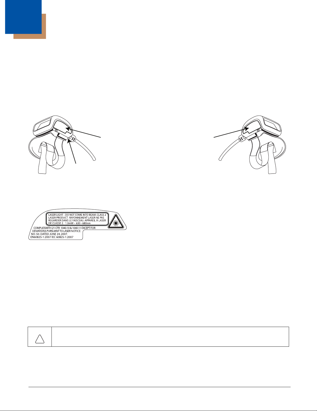
1
Laser Safety Label
Part Number and Serial Number Label
Compliance Label
!
Ring Scanner Agency Compliance
Ring bar code decoders meet or exceed the requirements of all applicable standards organizations for safe operation. However,
as with any electrical equipment, the best way to ensure safe operation is to operate them according to the agency guidelines
that follow. Read these guidelines carefully before using your Ring Scanner.
This documentation is relevant for the following models: 8600 series (861x, 862x) Ring Scanners.
Label Locations
Left Side of Scanner head Right Side of Scanner Head
Laser Label
If the following label is attached to your ring bar code decoder, it indicates the ring bar code decoder contains an engine with a
laser aimer:
Laser Safety Statement
This device has been tested in accordance with and complies with IEC60825-1:2007 and EN60825-1:2007). Complies with 21
CFR 1040.10 and 1040.11, except for deviations pursuant to Laser Notice No. 50, dated June 24, 2007.
LASER LIGHT, DO NOT STARE INTO BEAM, CLASS 2 LASER PRODUCT, 1.0 mW MAX OUTPUT: 630-680nM.
Laser Warnings
• Do not look into the laser’s lens.
• Do not stare directly into the laser beam.
• Do not remove the laser caution labels from the Ring Scanner ring bar code decoders.
• Do not connect the laser bar code aperture to any other device. The laser bar code aperture is certified for use with either the
HX2/HX3 or the Dolphin 70e Black in the Honeywell Wearable Solution only.
Caution:
Laser radiation when open. Read the caution labels. Use of controls, adjustments or performance of procedures
other than those specified herein may result in hazardous radiation exposure.
1 - 1
Page 12
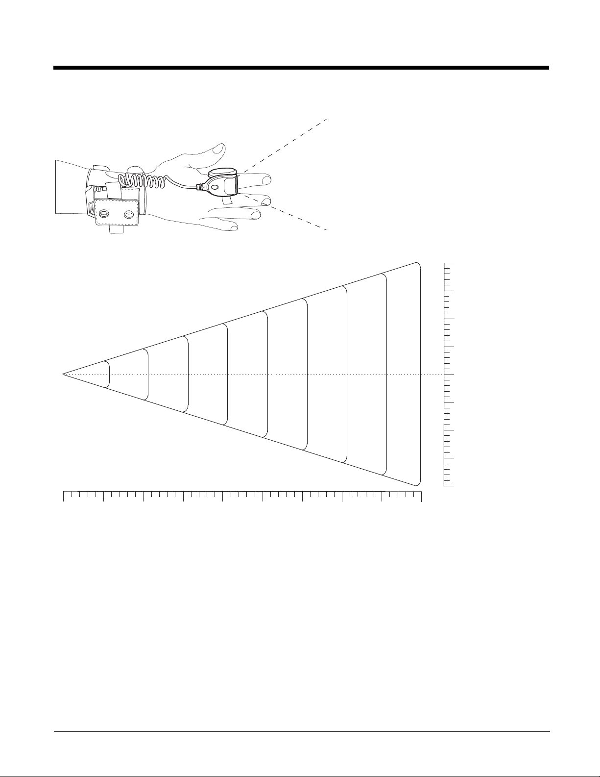
Beam Divergence
See dimension
of eld below
20” 50.8 cm
15” 38.1 cm
10” 31.6 cm
5” 12.7 cm
0” 0 cm
20” 50.8 cm
15” 38.1 cm
10” 31.6 cm
5” 12.7 cm
0”
5”
12.7 cm
10”
25.4 cm
15”
38.1 cm
20”
50.8 cm
25”
63.5 cm
30”
76.2 cm
35”
88.9 cm
40”
101.6 cm
45”
114.3 cm
Width of Field
0 cm
Depth of Field
FCC Part 15 Statement
This device has been tested and found to comply with the limits for a Class B digital device, pursuant to Part 15 of the FCC
Rules.
These limits are designed to provide reasonable protection against harmful interference in a residential installation.
This equipment generates, uses and can radiate radio frequency energy and, if not installed and used in accordance with the
instructions, may cause harmful interference to radio communications.
1 - 2
Page 13

Canadian Compliance
10
This ISM device complies with Canadian RSS-210.
Operation is subject to the following conditions:
1. This device may not cause harmful interference.
2. This device must accept any interference received, including interference that may cause undesired operation.
This Class B digital apparatus complies with Canadian ICES-003.
IMPORTANT NOTE:
Radiation Exposure Statement:
This equipment complies with IC radiation exposure limits set forth for an uncontrolled environment. End users must follow the
specific operating instructions for satisfying RF exposure compliance. To maintain compliance with IC RF exposure compliance
requirements, please follow operation instruction as documented in this manual.
CE Mark
The CE marking indicates compliance with the following directives:
• 1995/5/EC R&TTE
• 2011/65/EU RoHS (Recast)
In addition, complies to 2006/95/EC Low Voltage Directive, when shipped with recommended power supply. European contact::
Hand Held Products Europe BV
Nijverheidsweg 9-13
5627 BT Eindhoven
The Netherlands
Honeywell shall not be liable for use of our product with equipment (i.e., power supplies, personal computers, etc.) that is not CE
marked and does not comply with the Low Voltage Directive.
Honeywell Scanning & Mobility Product Environmental Information
Refer to www.honeywellaidc.com/environmental for the RoHS / REACH / WEEE information.
China RoHS
有毒有害物质名称及含量的标识 (Names and Content of Hazardous Substances or Elements)
部件名称 (Parts Name) 有毒有害物质或元素 (Toxic and Hazardous Substances or Elements)
铅 (Pb) 汞 (Hg) 镉 (Cd) 六价铬 (Cr6+) 多溴联苯 (PBB) 多溴二苯醚 (PBDE)
扫描模块 (Scanner Module)
印刷电路部件 (PCA)
外壳 (Housing)
连接线 (Cable)
o: 表示该有毒有害物质在该部件所有均质材料中的含量均在 SJ/T11363-2006 标准规定的限量要求以下 (Indicates that this toxic or hazardous substance contained in all of the
homogeneous materials for this part is below the limit requirement in China’s SJ/T11363-2006)
x: 表示该有毒有害物质至少在该部件的某一均质材料中的含量超出 SJ/T11363-2006 标准规定的限量要求 (Indicates that this toxic or hazardous substance contained in at least one of
the homogeneous materials for this part is above the limit requirement in China’s SJ/T11363-2006)
xooooo
xooooo
xooooo
xooooo
Dealer License - Republic of Singapore
1 - 3
Page 14

1 - 4
Page 15

2
Getting Started
Overview
This guide contains installation and configuration instructions for the Honeywell 8650 Ring Scanner. The Ring Scanner is
available with either a 1D laser scanner or 2D laser imager.
Bar code decoding laser engines and imager engines are designed to read, decode and collect bar coded data from any nearby
compatible bar code label that is visible and on printed media.
The ring scanner consists of a ring decoder with a cable to tether to a Honeywell HX2 or HX3. The HX2 or HX3 provides power
to the ring decoder. The hand strap assembly is designed to be worn on the back of either hand..
The Ring Scanner is compatible with the Honeywell HX2 and HX3. The ring scanner communicates to the serial port on the
HX2 or HX3 via the cable connection.
For information about other scanners, such as internal scanners, scanners connected to a COM port or Bluetooth scanners,
refer to www.honeywellaidc.com or the scanner manufacturer’s website.
About this Guide
This guide provides instruction for the end-user or system administrator to follow when setting up a new Ring Scanner bar code
decoder. This guide includes all programming bar codes and decode zones.
Out of the Box
After you open the shipping carton verify it contains the following items:
• Ring bar code decoder
• Hand strap
• Quick Start Guide
If you ordered accessories for the 8600-series Ring Scanner, verify they are also included with the order. Keep the original
packaging material in the event the Ring Scanner should need to be returned for service. For details, see Product Service and
Repair (page 7-1).
2 - 1
Page 16
Initial Setup
Following are the steps you might take when setting up a new Ring Scanner. More instruction for each step is listed later in this
guide. Contact Customer Support (page 7-1) if you need additional help.
Accessory installation or removal should be performed on a clean, well-lit surface. When necessary, protect the work surface,
the Ring Scanner, and components from electrostatic discharge.
Hardware Setup
1. Determine which hand will contain the assembly. See Determine Left or Right Orientation (page 2-3).
2. Connect the ring cable connector to the body worn computer. See Connect to Terminal (page 2-4).
Components
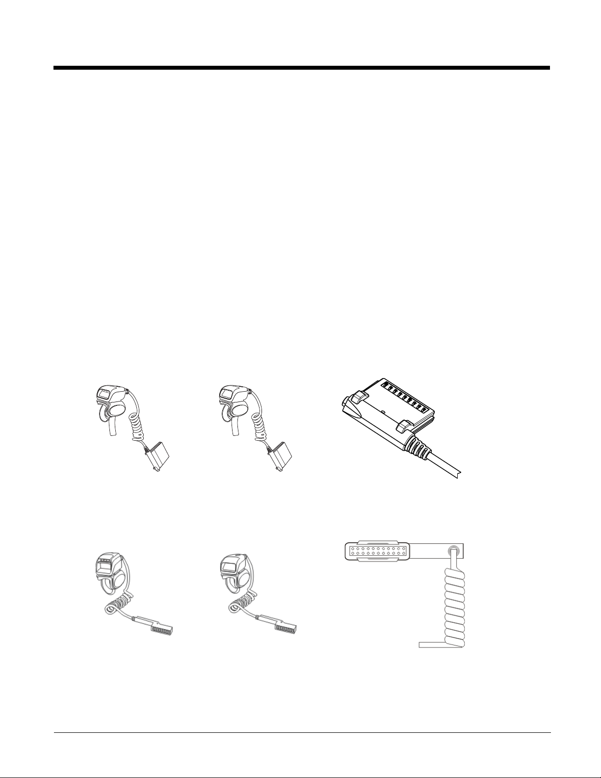
Ring Imager / Ring Scanner
The ring imager can scan and decode 1D and 2D bar codes. The imager has three small illumination LEDs at the top of the
scan window or aperture.
The ring scanner can scan and decode 1D bar codes. The scanner does not have illumination LEDs.
The ring sends the collected bar code data to the mobile computer for processing.
Do not touch, push against or brace your finger on the scan aperture at any time.
When new, there is a clear, tabbed protective film covering the ring decoder scan window. Remove and discard the clear,
tabbed protective film before scanning a bar code.
Ring Imager / Ring Scanner for Dolphin 70e Black in Wearable Sled.
2 - 2
Ring Imager Ring Scanner Cable Connector
Ring Imager / Ring Scanner for HX2 and HX3.
Ring Imager Ring Scanner Cable Connector
Page 17

Assembly
Determine Left or Right Orientation
Determining whether to wear the module assembly on the left or right has a bearing on how the ring cable is attached to the
module and the ring to the finger. The ring cable should not cross over or under the hand.
Adjusting the Ring Device Strap
The ring device finger loop is located under the ring device. The ring device has a built-in quick disconnect designed for safety
hazards. The quick disconnect is not intended for daily removal of the ring device.
1. Pull gently on the end of the finger loop strap to separate the hook and loop fabric.
2. Slide your finger into the opened loop under the ring device.
3. Grasp the end of the finger loop strap and gently pull to loosen then tighten the finger strap until the ring device is
comfortably snug and the scan aperture is in the desired location.
4. Secure the ring strap at the desired location by pressing the hook fabric to the loop fabric on the strap surrounding the finger.
2 - 3
Page 18
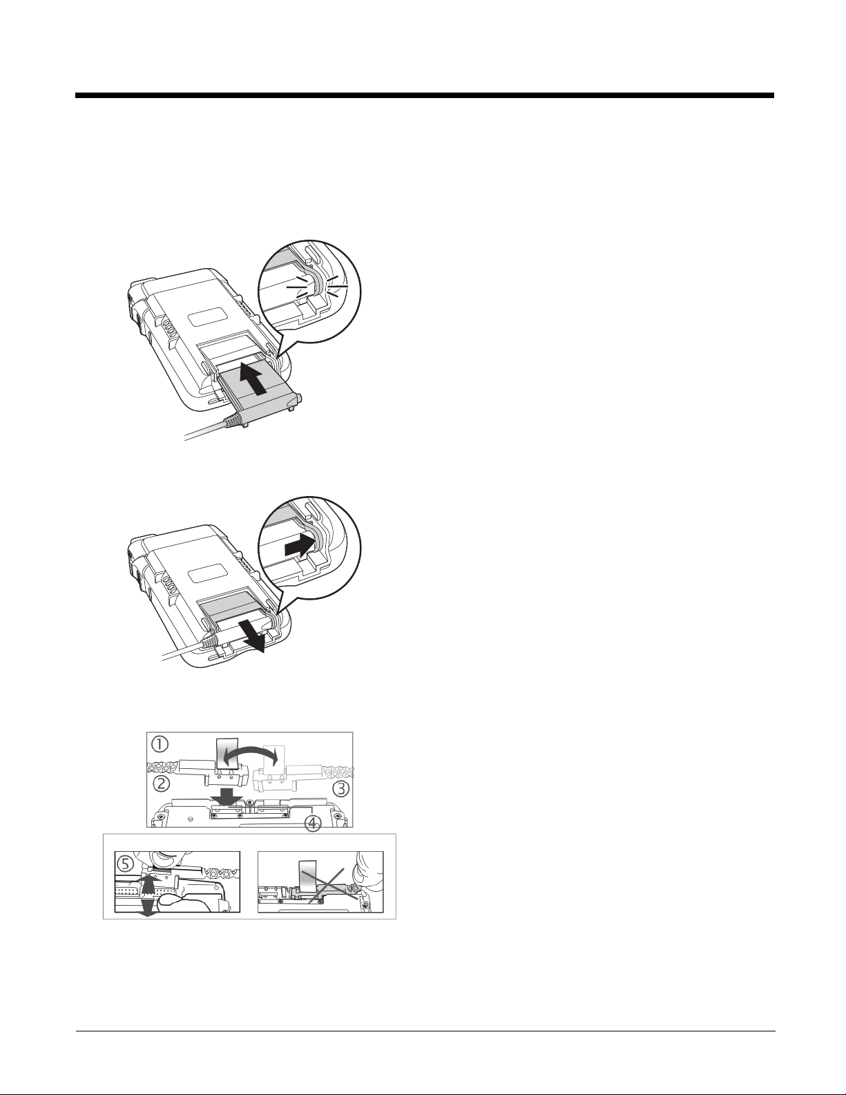
Connect to Terminal
1
2
Dolphin 70e in Wearable Sled
Connect
Disconnect
1. Slide the ring scanner cable connector into the bottom
of the sled until the connector ring clicks shut.
1. To eject the ring scanner, open the connector ring with
one hand, pulling toward the outside of the sled.
2. Push the ring scanner connector out of the sled.
HX2 / HX3
1. Connect
2. Ring on Left Hand
3. Ring on Right Hand
4. Press Down
5. Remove
When you want to switch connectors from left to right, or vice versa, first gently press downward on the Retaining Clip, then
pinch and pull the cable connector (not the cable!) straight up and away from the Ring Scanner. Do not use a metal object,
or extreme force, to remove the cable connector from the Ring Scanner.
Re-connect cables and reassemble the Ring Scanner body-worn components.
2 - 4
Page 19

Removing / Replacing the Trigger Module
Equipment Needed: Phillips screwdriver with a blade diameter of 1/8” (.4mm). Not supplied.
Caution: Do not perform the following procedures if the ring bar code reader is tethered to a mobile computer There is a
possibility the Scan button may be pressed inadvertently and the laser beam emitted. Disconnect the ring scanner before
attempting to remove or replace the trigger module.
Do not touch, push on or brace your finger against the scan aperture at any time.
Installing and removing accessories should be performed on a clean, well-lit surface. When necessary, protect the work
surface, the mobile device, and components from electrostatic discharge.
A 20-pak of full Trigger assemblies is available. Contact Customer Support (page 7-1) for the latest updates and accessories.
Remove Finger Strap Assembly
Fold the flexible liner back until the screw hole is visible.
Rotate the trigger module until the black screw is visible.
1. Using a Phillips screwdriver with a blade diameter of 1/8” (.4mm) loosen the black screw counter-clockwise and set the
screw aside in a safe place.
2. Remove the trigger module.
Replace Trigger Module
1. Position the trigger module on the base of the Ring Scanner, making sure the empty screw hole is visible.
2. Find the tiny black screw that you removed previously.
3. Using a Phillips screwdriver with a blade diameter of 1/8” (.4mm) rotate the black screw clockwise until the trigger
module is secured to the ring scanner.
4. Install the finger strap.
5. Removing / Replacing the Ring Finger Strap Assembly
Note: Do not pull on the finger strap or the flexible liner to remove the finger strap assembly. This quick disconnect function is
designed for occasional safety hazards and is not intended for daily removal.
Using the Quick Disconnect Function, grasp the finger strap and pull the finger strap out and away from the ring scanner.
Before attaching the finger strap to the trigger module, thread the finger strap first through the hinge, then under and over the pin
next to the scan button.
It should slide easily.
Cleaning the Beam Aperture
Note: These instructions are for components made of glass. If there is a removable protective film sheet on the beam aperture,
remove the film sheet before cleaning and before first use.
Keep fingers and rough, sharp or abrasive objects away from the beam aperture.
If the aperture becomes soiled or smudged, clean only with a standard household cleaner such as Windex® without vinegar or
use Isopropyl Alcohol.
Do not use paper towels or harsh-chemical-based cleaning fluids since they may result in damage to the aperture surface. Use
a clean, damp, lint-free cloth. Do not scrub optical surfaces.
If possible, clean only those areas which are soiled. Lint/particulates can be removed with clean, filtered canned air.
2 - 5
Page 20
How To Scan a Bar Code
The function to use an imager like a camera (or for OCR decoding) is not supported. Using a Continuous Scan option, if
available, to scan programming bar codes is not supported.
The linear bar codes in this guide were created using Code 128 symbology. Your Ring Scanner has been set up by Honeywell
to automatically read / decode Code 128 bar codes.
Using the bar codes contained in this guide, you can change bar code reader system parameters or reset all parameters to their
factory default values.
It is important to use the correct bar codes when programming the scanner/imager:
• 1D Laser Scanner Programming Bar Codes (page 3-1)
• 2D Laser Imager Programming Bar Codes (page 4-1)
All bar code reader parameters are programmed into and stored by the bar code reader engine.
If this guide is not in print form, locate the page in this electronic guide that contains the bar code you wish to use. Print the
page on white paper using a 600dpi laser printer (or equivalent).
Print the page containing the Reset and Cancel bar codes as well as the page containing the A – F and 0 – 9 number bar codes.
Select the parameter you want to scan. If this guide is in print form, lay it flat on a table or propped up at an angle.
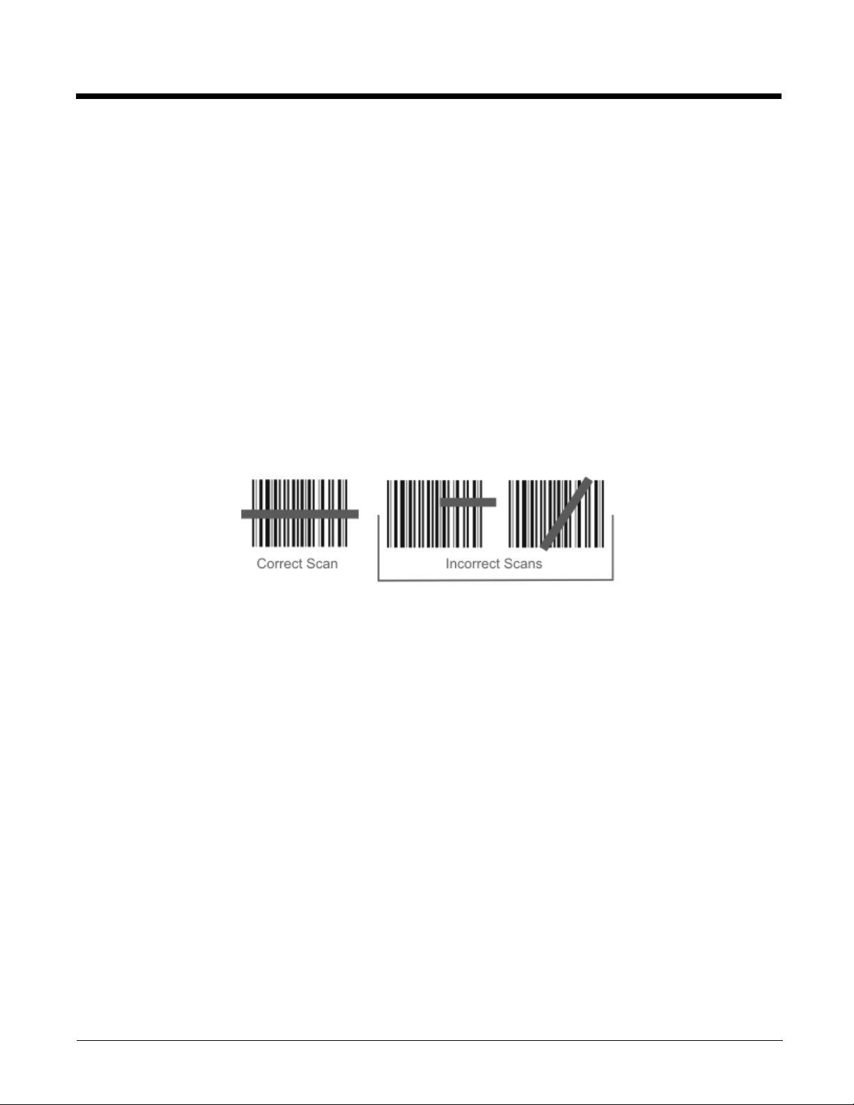
Scan a Linear Bar Code
Holding the beam aperture approximately 3 – 12 inches away from the bar code, aim the scan aperture toward the selected
bar code. Refer to the bar code reader engine type in Decode Zones later in this guide for recommended decode ranges.
Press the Scan button. Align the scan beam so that the bar code is centered within the beam. The beam must cross the
entire bar code. Move the bar code reader towards or away from the bar code so that the bar code takes up approximately
two-thirds the width of the beam.
Refer to the recommended decode zones for the ring bar code reader engine if you are having difficulty with this process.
Do not position the scan aperture exactly perpendicular to the bar code being read. In this position, light can bounce back
into the scan aperture, and possibly prevent a successful decode.
Good Read / Bad Read Indicators
The scan On indicator illuminates (usually red) when the beam is on. Following a bar code scan and “good read” the indicator turns green indicating a successful scan. The connected mobile device may also beep or play a WAV file while
decoding the signal from the ring scanner.
The laser beam and scan On indicator automatically turn off after a successful or unsuccessful read and the bar code
reader is ready to scan again.
2 - 6
Page 21

Factors That May Impact Scanner Performance
Successful scanning range of a bar code decoder is dependent upon many outside influences including size of the bar code,
quality of the bar code printing, material the bar code is printed on, condition of the scan lens (scratches) and angle of the beam
aperture relative to the bar code label. Any of these factors may result in having to re-scan the label from a different distance or
angle.
Bar Code Quality
Check the bar code for marks or physical damage e.g., ripped label, missing section, correct size for the scanner being used,
etc.
In general, the bigger the bar code the further the distance from which it can be read. If the bar code is smaller than the
specified size for the scanner being used, the distance, in almost all cases, will shrink.
Large bar codes can be scanned at the maximum distance. Hold the scanner closer to small bar codes (or with bars that are
very close together).
Do not position the scanner exactly perpendicular to the bar code being scanned. In this position, light can bounce back into the
scan aperture, and possibly prevent a successful decode.
Bar Code Source
Using a graphics program to clip/copy a bar code from an online file (e.g., Adobe, Word) will copy the bar code at your monitor's
dot per inch setting, a level too low for successful bar code scanning.
Copy a Bar Code -- Use your browser's right-click menu to download an individual bar code using the Save Picture As option.
Save the picture to a location on your computer's hard drive. The individual bar code can be added, as a file, to any delivery
vehicle e.g., email, Word document.
Bar Code Symbology
Bar codes such as UPC codes and Code 128 are more complex than Code 39 and Interleaved 2 of 5. When attempting to get
the maximum read distance possible, particularly with reflective labels, use Code 39. The use of Code 128 or other more
complex symbologies will almost always result in a reduction in maximum read distance. Scanner maximum distances (from
Decode Zones) when symbologies other than Code 39 are used are not supported.
Lens Damage
A scratched scan beam aperture can impact read rates and distances. Beam apertures should be inspected frequently,
particularly if scanning quality or distances get worse over time.
Ambient Lighting
High ambient conditions, particularly outdoor environments, will produce enough light to somewhat “blind” the scanner. This will
result in shorter read distances.
Temperature
While small deviations from room temperature will have no impact on scanner performance, severe conditions like those found
in freezers will have a negative impact on both the distance scanners can read and the speed the read is acquired.
Some scanner engines contain protection circuitry that shuts the scanner down in temperatures that exceed the recommended
operating temperature.
Bar Code Scanning Help
Notes
• Decrease decode time by disabling unused bar code types. The scan engine can store several different bar code symbologies
at the same time. This means the Ring Scanner is able to scan a Code 39 bar code, then an Interleaved 2 of 5 bar code, then
a different bar code without requiring a parameter reset.
• The mobile device Scanner (or Data Collection Wedge) panel parameters are applied to the data resulting from successful
bar code scans sent to the host (e.g., Thor VM2) for processing. The wedge panel does not affect or change the programming
bar code parameter settings in this guide.
• After scanning the Reset All to default (or equivalent) bar code with the tethered ring scanner, the next step is to open the
Scanner (or Data Collection Wedge) panel on the host, click the OK button and then close the panel. This action will
synchronize all scanner formats.
2 - 7
Page 22

Issue:
Bar codes on the printed page are too compact to be scanned, especially with a long range scanner.
Solution 1 - Printing Adobe Acrobat PDF File Pages:
When printing pages from an Adobe Acrobat PDF file, there is a difference between laser printer types and how they handle
some Adobe Acrobat print functions – specifically, the “shrink to fit” option on the Print Options screen. Before clicking Print,
make sure the “Shrink oversized pages to paper size” checkbox is unchecked. If the bar code is still too small to be read by the
scanner engine, run the printed page through the laser printer again using the laser printer’s Zoom feature until the bar code is
large enough to scan satisfactorily.
When printing pages from an on-line Web page, run the printed page through a laser copier using the laser copier's Zoom
feature until the bar code is large enough to scan satisfactorily.
Solution 2 - Printing from a Browser Page:
Use the Print button on the browser menu. Bar codes must be printed at 600 dots per inch (dpi) before they can be successfully
scanned with a bar code reader.
Miscellaneous Programmable Bar Codes
Beep After Good Decode
Audible scan progress indicators are generated by the scanner driver on mobile devices, not the bar code decoder engine.
Use the Windows wedge panel options to set up the mobile device audible indicators.
Beeper Frequency Adjustment
Audible scan progress indicators are generated by the scanner driver on mobile devices, not the bar code decoder engine.
Use the Windows wedge panel options to set up the mobile device audible indicators.
Event Reporting
Mobile devices aren’t designed to process events triggered by a bar code decoder engine. Events are processed by the
operating system resident on the mobile device. Use Windows Control Panel options to set up the mobile device event
reporting parameters.
LED Mode
This parameter is disabled/inactive as the scan LEDs are controlled by the scanner driver, not the scanner engine.
2 - 8
Page 23

Return to Factory Default Settings
Choose one of the following methods to restore factory defaults in the module, scan the Set Default Parameter (page 3-6)
or Set All Defaults/Cancel Bar Codes (page 4-5)bar code.
Important: - HX2 and HX3 only:
After resetting the module to factory default settings, the next step is to open the bar code wedge panel on the host mobile
device collecting the scanned data. Click the OK button to close the panel. This action will synchronize all scanner formats.
2 - 9
Page 24

2 - 10
Page 25

3
1D Laser Scanner Programming Bar Codes
Introduction
These bar codes, explanations and instructions are for programming the SE955 laser scanner engine in your ring scanner. Do
not scan the bar codes in this section with any other imager or laser engine.
Note: A ring scanner does not have beep / audio capability.
Assumption: The user is familiar with Windows on-screen functions.
Scan engine manufacturers may offer more bar codes and options than are contained in this chapter. Note that the bar codes in
this chapter are only those supported by Honeywell and the mobile devices it manufactures or supports. Contact Customer
Support (page 7-1) if you need help using the bar codes in this guide.
To change a parameter value: Scan the appropriate bar code in this section. The new value replaces the standard default
value in memory.
The following bar code symbologies are supported on the Ring Scanner:
Symbology
DataBar (RSS)
GS1Chinese 2 of 5
Codabar
Code 11
Code 128
Code 39
Code 93
Discrete 2 of 5
Interleaved 2 of 5
MSI Plessey
GS1 Databar (RSS) and Composite Codes
UPC/EAN
UPC-A
UPC-E
UPC-E1
EAN-8
EAN-13
3 - 1
Page 26

Aiming Modes
There are many aiming “modes” for laser bar code scanners – aiming dots, aiming patterns, aim duration, etc. All aiming
“modes” concern the length of time the beam is sent out, how wide the beam is and what happens when the timer expires. The
terms are used interchangeably and may be confusing for the novice bar code laser scanner user.
Note: Decoding algorithms released by the bar code engine manufacturer often change upon each new release. Programming
parameters that were available at one release may not be available upon a later software release. Honeywell supports
the programming bar codes for the specific engines in this guide only.
SE955 Ring Scanner
The scan engine can have it's aiming beam/aiming dot setup using these bar codes:
• Use Laser On Time (page 3-14)
• Aim Duration (page 3-7), and
• Scan Angle (SE955 only) (page 3-17)
Aiming Dot Help
How to get an aiming dot when there is no “Aiming Dot” parameter:
Set Aim Duration to .5 seconds and an aiming “dot” is sent while the scan trigger is held down. When the timer expires, the
aiming beam widens and the bar code is read.
Prefix / Suffix
Ring decoder engine prefix and suffix parameters should not be set, changed, or reset using the Prefix and Suffix bar codes
shown in this section. When the Ring Scanner module is reset to defaults, the prefix and suffix settings revert to their default
values and need to be scanned again. Use the ScanWedge NGW Power Tool (Dolphin 70e) or Scanner control panel (HX2 or
HX3) in the host computer to store prefix and suffix values.
Refer to the host computer’s user guide for information and instruction on setting up the following scanner parameters:
• Enable/Disable decoding sounds
• Imager LED Illumination
• COM1 Serial Parameters
• Code ID: AIM, Symbol, Custom
• Symbology Settings including Prefix/Suffix
• Control Character Mapping
• Custom Identifiers
• Pre-Configured Default Values
Ring Scanner Setting 955 Default
Set Default Parameter (page 3-6) All Defaults
Scanning Options
Aim Duration (page 3-7) 0.0 sec
Aiming Mode Not Supported
Beeper Volume Not Supported
Bi-Directional Redundancy (page 3-7) Disable
Laser On Time (page 3-14) 3.0 sec.
Linear Code Type Security Level (Redundancy Level) (page
3-15)
Parameter Pass Through (page 3-16) Disable
Parameter Scanning (page 3-16) Enable
Power Mode (page 3-17) Low Power
Raster Expansion Rate Not Supported
Raster Height Not Supported
1
3 - 2
Page 27

Ring Scanner Setting 955 Default
Scan Angle (SE955 only) (page 3-17) Wide
Scanning Mode Not Supported
Time Delay to Low Power Not Supported
Time-out Between Different Symbols Not Supported
Time-out Between Same Symbol Not Supported
Transmit “No Read / Decode” Message (page 3-24) Disable
Trigger Mode (page 3-25) Host
UPC/EAN
UPC-A (page 3-52) Enable
UPC-E (page 3-52) Enable
UPC-E1 (page 3-53) Disable
EAN-8 (page 3-53) Enable
EAN-13 (page 3-54) Enable
Bookland EAN (page 3-54) Disable
Bookland ISBN Format (page 3-55) Bookland ISBN-10
Decode UPC/EAN Supplementals (page 3-62) Ignore
Decode UPC/EAN Supplemental Redundancy (page 3-64) 7
Transmit UPC-A Check Digit (page 3-55) Enable
Transmit UPC-E Check Digit (page 3-56) Enable
Transmit UPC-E1 Check Digit (page 3-56) Enable
UPC-A Preamble (page 3-59) System Character
UPC-E Preamble (page 3-60) System Character
UPC-E1 Preamble (page 3-61) System Character
Convert UPC-E to UPC-A (page 3-57) Disable
Convert UPC-E1 to UPC-A (page 3-57) Disable
Convert EAN-8 to EAN-13 Type (page 3-58) Type is EAN-13
EAN-8 Zero Extend (page 3-65) Disable
UPC/EAN Security Level (page 3-66) 0
UCC Coupon Extended Code (page 3-65) Disable
Linear UPC/EAN Decode Not Supported
UPC Half Block Stitching Not Supported
UPC Composite Mode Not Supported
Code 128
Code 128 (page 3-33) Enable
GS1-128 (formerly UCC/EAN-128) (page 3-33) Enable
ISBT-128 (page 3-34) Enable
Code 128 Decode Performance Not Supported
Code 128 Decode Performance Level Not Supported
Code 39
Code 39 (page 3-35) Enable
Trioptic Code 39 (page 3-39) Disable
Convert Code 39 to Code 32 (page 3-36) Disable
Code 32 Prefix (page 3-36) Disable
Set Lengths for Code 39 (page 3-37) Length within Range: 02 – 55
3 - 3
Page 28

Ring Scanner Setting 955 Default
Code 39 Check Digit Verification (page 3-35) Disable
Transmit Code 39 Check Digit (page 3-39) Disable
Code 39 Full ASCII Conversion (page 3-37) Disable
Code 39 Decode Performance Not Supported
Code 39 Decode Performance Level Not Supported
Code 93
Code 93 (page 3-40) Disable
Set Lengths for Code 93 (page 3-40) Length within Range: 04 – 55
Code 11
Code 11 (page 3-30) Disable
Set Lengths for Code 11 (page 3-30) Length within Range: 04 – 55
Code 11 Check Digit Verification (page 3-32) Disable
Transmit Code 11 Check Digits (page 3-32) Disable
Interleaved 2 of 5
Interleaved 2 of 5 (page 3-44) Enable
Set Lengths for I 2 of 5 (page 3-45) 14
I 2 of 5 Check Digit Verification (page 3-44) Disable
Transmit I 2 of 5 Check Digit (page 3-47) Disable
Convert I 2 of 5 to EAN-13 (page 3-45) Disable
Discrete 2 of 5
Discrete 2 of 5 (page 3-42) Disable
Set Lengths for Discrete 2 of 5 (page 3-42) 12
Chinese 2 of 5
Chinese 2 of 5 (page 3-26) Disable
Codabar (page 3-27)
CLSI Editing (page 3-27) Disable
NOTIS Editing (page 3-28) Disable
Set Lengths for Codabar (page 3-28) Length within Range: 05-55
MSI Plessey
MSI Plessey (page 3-48) Disable
Set Lengths for MSI Plessey (page 3-49) Length within Range: 06-55
MSI Plessey Check Digits (page 3-49) One
Transmit MSI Plessey Check Digit (page 3-51) Disable
MSI Plessey Check Digit Algorithm (page 3-48) Mod 10/Mod 10
PDF417/MicroPDF417
PDF417 Not Supported
MicroPDF417 Not Supported
Decode Linked Symbol Not Supported
Code 128 Emulation Not Supported
GS1 DataBar (RSS) Codes
GS1 DataBar Omnidirectional (RSS-14) (page 3-67) Disable
GS1 DataBar Limited (RSS-Limited) (page 3-67) Disable
Convert GS1 DataBar (RSS) to UPC/EAN (page 3-68) Disable
3 - 4
Page 29

Ring Scanner Setting 955 Default
Convert GS1 DataBar (RSS) to UPC/EAN Disable
Composite
CC-C Not Supported
CC-AB Not Supported
TLC-39 Not Supported
Data Options
Prefix and Suffix (page 3-8) Prefix: NULL, Suffix 1: LF, Suffix 2:CR
Scan Data Transmission Format (page 3-9) Data as is
Transmit Code ID Character (page 3-11) None
Decode Buffering Not Supported
Simple Serial Interface (SSI) Options
Baud Rate (page 3-18) 9600
Parity (page 3-20) None
Check Parity Not Supported
Software Handshaking (page 3-22) Enable
Decode Data Packet Format (page 3-19) Unpacketed
Stop Bit Select (page 3-23) 1
Intercharacter Delay (page 3-20) 0
Host Serial Response Time-out (page 3-19) 2 sec
Host Character Time-out (page 3-19) 200 msec
Macro PDF
Macro PDF Transmit/Decode Mode Not Supported
Transmit Each Symbol in Codeword Format Not Supported
Transmit Unknown Codewords Not Supported
Escape Character Not Supported
ECI
Delete Character Set ECIs Not Supported
ECI Decoder Not Supported
Transmit Macro PDF User-Selected Field
Transmit File Name Not Supported
Transmit Block Count Not Supported
Transmit Time Stamp Not Supported
Transmit Sender Not Supported
Transmit Addressee Not Supported
Transmit Checksum Not Supported
Transmit File Size Not Supported
Transmit Macro PDF Control Header Not Supported
Last Block Marker Not Supported
Flush Macro Buffer Not Supported
Abort Macro PDF Entry Not Supported
3 - 5
Page 30

Set Default Parameter
Restore Defaults
If custom defaults were set by scanning Write Custom Defaults, scan Restore Defaults to retrieve and restore the scanner’s
custom default settings. If no custom defaults were set, scan Restore Defaults to restore the factory default values.
Set Factory Defaults
Restore the factory default values. If custom defaults were set, they are eliminated.
Write Custom Defaults
Store the current scanner settings as custom defaults. Once custom default settings are stored, they can be recovered at
any time by scanning the Restore Defaults bar code.
Restore Defaults
Set Factory Defaults
Write Custom Defaults
See Also: Return to Factory Default Settings (page 2-9).
3 - 6
Page 31

Scanner Parameters – General
Aim Duration
Note: For correct operation, reboot the mobile device after changing this value.
When a scanner with an aim mode is triggered either by a Scan button press, or a Start_Decode command, this parameter
sets the duration the aiming pattern is seen before a scan attempt begins. It does not apply to the aim signal or the
Aim_On command. It is programmable in 0.1 second increments from 0.0 to 9.9 seconds. No aim pattern is visible when
the value is 0.0.
To set aim duration, scan the bar code below:
Next scan two numeric bar codes that correspond to the desired aim duration. Times less than 1.0 second must have a
leading zero. For example, to set an aim duration of 0.5 seconds, scan the bar code above, then scan the “0” and “5” bar
codes on Keypad Number Symbols (page 3-72). If you make an error, or wish to change your selection, scan the Cancel
bar code.
Bi-Directional Redundancy
Use this parameter to decide whether a bar code is successfully scanned in both directions before being decoded.
Note: This parameter is only valid when a Linear Code Type Security Level (Redundancy Level) (page 3-15) has been
enabled. The default for Security Level parameter is Level 1.
Select an option by scanning either of the bar codes shown below.
Enable Bi-Directional Redundancy
* Disable Bi-Directional Redundancy
3 - 7
Page 32

Disable All Symbologies
Scan the bar code below to disable the decoding of all symbologies. Use this to simplify selecting a single symbology to
decode by scanning this bar code, then scanning the desired enable code type bar code.
Note that the decoder can still decode parameter bar codes.
Data Options
Note: SE955 ring scanner engine prefix and suffix parameters cannot be set, changed, or reset using the bar codes in this
chapter. See previous section titled Prefix / Suffix (page 3-2).
Prefix and Suffix
Ring decoder engine prefix and suffix parameters should not be set, changed, or reset using the Prefix and Suffix bar
codes shown in this section. When the Ring Scanner Module is reset to defaults, the prefix and suffix settings revert to their
default values and need to be scanned again. Use the ScanWedge NGW Power Tool (Dolphin 70e) or Scanner control
panel (HX2 or HX3) in the host computer to store prefix and suffix values.
Setting Default
Prefix (P) Null
Suffix1 (S1) LF
Suffix2 (S2) CR
Scan Data Transmission Format (page 3-9) must be set before selecting Prefix/Suffix values.
A prefix and/or one or two suffixes may be appended to scan data for use in data editing. These values are set by scanning
four bar codes (resulting in a four digit number) that correspond to key codes for various mobile devices. See the table titled
“ASCII Character Equivalents”.
If you wish to change your selection, scan this Data Format Cancel bar code:
Prefix
To begin setting Prefix values, scan this bar code:
Next, scan four numeric bar codes that correspond to the computer keycode using the Keypad Number Symbols (page
3-72).
If you wish to change your selection, scan Cancel on the Keypad Number Symbols page.
Suffix 1
To begin setting Suffix 1 value, scan this bar code:
3 - 8
Page 33

Next, scan four numeric bar codes that correspond to the computer keycode using the Keypad Number Symbols (page
3-72).
If you wish to change your selection, scan Cancel on the Keypad Number Symbols page.
Suffix 2
To begin setting Suffix 2 value, scan this bar code:
Next, scan four numeric bar codes that correspond to the computer keycode using the Keypad Number Symbols (page
3-72).
If you wish to change your numeric selection, scan Cancel on the Keypad Number Symbols page.
Scan Data Transmission Format
Note: Parameter Prefix and Suffix (page 3-8) should be set after setting this parameter.
Use this option when you want to append a prefix and suffix to the decode data.
Set this parameter by scanning one of the following bar codes.
* Data As Is
[Data] [Suffix 1]
[Data] [Suffix 2]
3 - 9
Page 34

[Data] [Suffix 1] [Suffix 2]
[Prefix] [Data]
[Prefix] [Data] [Suffix 1]
[Prefix] [Data] [Suffix 2]
[Prefix] [Data] [Suffix 1] [Suffix 2]
3 - 10
Page 35

Transmit Code ID Character
Default Value: None
A code ID character identifies the code type of a scanned bar code. This may be useful when the scanner is decoding
more than one code type. In addition to any single character prefix already selected, the code ID character is inserted
between the prefix and the decoded symbol.
Scan one of the following bar codes to select either no code ID character, a Symbol Code ID character or an AIM Code ID
character.
Transmit No Code ID Character
Transmit Symbol Code ID Character
A UPC-A, UPC-E, UPC-E1, EAN-8, EAN-13
B Code 39, Code 32
C Codabar
D Code 128, ISBT 128
E Code 93
F Interleaved 2 of 5
G Discrete 2 of 5 or Discrete 2 of 5 IATA
H Code 11
J MSI Plessey
K UCC/EAN-128
L Bookland EAN
M Trioptic Code 39
N Coupon Code
R GS1 DataBar Omnidirectional (RSS-14),
GS1 Limited (RSS-Limited),
GS1 Expanded (RSS-Expanded)
3 - 11
Page 36

Transmit AIM Code ID Character
Each AIM Code Identifier contains the three character string ]cm where:
]= Flag Character (ASCII 93)
c= Code Character
A Code 39
C Code 128
E UPC/EAN
F Codabar
G Code 93
H Code 11
I Interleaved 2 of 5
M MSI Plessey
S D2 of 5, IATA 2 of 5
X Code 39 Trioptic, Bookland EAN
e GS1 DataBar (RSS)
m= Modifier Character
The modifier character is the sum of the applicable option values based on the following table.
Code
Typ e
Code 39
0 No Check character or Full ASCII processing.
1 Reader has checked one check character.
3 Reader has checked and stripped check character.
4 Reader has performed Full ASCII character conversion.
5 Reader has performed Full ASCII character conversion and checked one check character.
7 Reader has performed Full ASCII character conversion and checked and stripped check
Example: A Full ASCII bar code with check character W,A+I+MI+DW, is transmitted as ]A7AimId
Trioptic Code 39
0 No option specified at this time. Always transmit 0.
Example: A Trioptic bar code 412356 is transmitted as ]X0412356
Code 128
0 Standard data packet, No Function code 1 in first symbol position.
1 Function code 1 in first symbol character position.
2 Function code 1 in second symbol character position.
Option
Val ue
Option
character.
where 7 = (3+4).
Example: A Code (EAN) 128 bar code with Function 1 character in the first position,
Id is transmitted as ]ClAimId
FNC1
Aim
3 - 12
Page 37

Code
Typ e
Interleaved 2 of 5
0 No check digit processing.
1 Reader has validated check digit.
3 Reader has validated and stripped check digit .
Example: An I 2 of 5 bar code without check digit, 4123, is transmitted as ]I04123
Codabar
0 No check digit processing.
1 Reader has checked check digit.
3 Reader has stripped check digit before transmission.
Example: A Codabar bar code without check digit, 4123, is transmitted as ]F04123
Code 93
0 No options specified at this time. Always transmit 0.
Example: A Code 93 bar code 012345678905 is transmitted as ]G0012345678905
MSI (Plessey)
0 Single check digit checked.
1 Two check digits checked.
2 Single check digit verified and stripped before transmission.
3 Two check digits verified and stripped before transmission.
Example: An MSI Plessey bar code 4123, with a single check digit checked, is transmitted as
Discrete 2 of 5
0 No options specified at this time. Always transmit 0.
Example: A D 2 of 5 bar code 4123, is transmitted as ]S04123
UPC/EAN
0 Standard packet in full EAN country code format, which is 13 digits for UPC-A and UPC-E (not
1 Two digit supplement data only
2 Five digit supplement data only
4 EAN-8 data packet.
Example: A UPC-A bar code 012345678905 is transmitted as ]E00012345678905
Bookland EAN
0 No options specified at this time. Always transmit 0.
Example: A Bookland EAN bar code 123456789X is transmitted as ]X0123456789X
Option
Val ue
Option
]M04123
including supplemental data).
According to AIM standards, a UPC with supplemental bar code is transmitted in the following format:
]EO (UPC chars) (terminator) ]E2 (supplemental) (terminator)
Therefore, a UPC with two supplemental characters, 01234567890510, is transmitted to the host as a 21-character
string, ]E00012345678905]E110.
3 - 13
Page 38

Laser On Time
Note: For correct operation, reboot the Bluetooth Ring Scanner after changing this value.
Default: 3.0 seconds
This parameter sets the maximum time decode processing continues during a scan attempt. It is programmable in 0.1 sec-
ond increments from 0.50 to 25.5 seconds. If a label has not been decoded before this time expires and the session is terminated, the system regards it as a failed scan attempt.
To begin setting Laser On Time, scan this bar code:
Next, scan two numeric bar codes that correspond to the desired on time using the Keypad Number Symbols (page 3-72).
Times less than 1.0 second must have a leading zero.
If you wish to change your number selection, scan Cancel on the Keypad Number Symbols page.
See Also: Laser On Time (superseded) (page 3-69)
3 - 14
Page 39

Linear Code Type Security Level (Redundancy Level)
Use this parameter to determine the security level appropriate for bar code quality. The security level indicates how many
times the bar code must be successfully read by the scanner before being decoded.
There are four security levels. Higher security levels are selected for decreasing levels of bar code quality. As security levels increase, the scanner’s aggressiveness decreases.
Select an option by scanning one of the bar codes shown below. If you wish to change your selection, scan Cancel.
Level 1 The following code types must be successfully read twice before being decoded:
Codabar : All lengths
MSI Plessey : Length of 4 characters or less
D 2 of 5 : Length of 8 characters or less
I 2 of 5 : Length of 8 characters or less
Level 2 All code types must be successfully read twice before being decoded.
Level 3 Code types other than the following must be successfully read two times before being decoded. The
following codes must be read three times:
MSI Plessey : Length of 4 characters or less
D 2 of 5 : Length of 8 characters or less
I 2 of 5 : Length of 8 characters or less
Level 4 All code types must be successfully read three times before being decoded.
Note: Linear Code Type Security does not apply to Code 128.
* Level 1
Level 2
Level 3
Level 4
3 - 15
Page 40

Parameter Pass Through
Enable Parameter Pass Through to transmit bar codes in the following format, in Code 128, to the host:
<FNC3>L<any length data>
<FNC3>B<12 characters of data>
Note that the special Code 128 character <FNC3> must appear at the beginning of this data. However, if the appropriate
data does not follow this as shown above, it does not transmit to the host device.
Enable Parameter Pass Through
* Disable Parameter Pass Through
Parameter Scanning
Use this parameter to decide whether scanner parameters can be set using the bar codes in this section.
Note: When this parameter is disabled, scan the Set Default Parameter (page 3-6) bar code to enable parameter scanning.
When disabled, either scan the Enable Parameter Scanning bar code or the Set All Defaults bar code (or set this parameter
to 01h via a serial command) to reset the parameter and bar codes in this section can then be scanned.
When enabled, scanners can be configured using the bar codes in this section.
Select a mode by scanning either of the bar codes shown below.
* Enable Parameter Scanning
Disable Parameter Scanning
3 - 16
Page 41

Power Mode
Note: Mobile devices are designed to be operated in Low Power Mode. For best results this value should remain
unchanged.
Note: A parameter setting of Continuous On means the laser scanner will not power down until the mobile device is
powered off.
A parameter setting of Low Power means the laser scanner will enter low power mode after one second of waiting for a
Scan button press. Pressing the Scan button will begin the decode sequence.
Select a Power Mode by scanning either of the bar codes shown below.
Continuous On
* Low Power
Scan Angle (SE955 only)
Choose one of the options below to set the scan angle to narrow or wide. Once the parameter bar code is scanned, the
Scan Angle setting is persistently stored.
Select an option by scanning one of the bar codes shown below.
Narrow Angle (35°)
* Wide Angle
See Also: Scan Angle (SE955 only) superseded (page 3-69)
3 - 17
Page 42

Simple Serial Interface (SSI) Options
The SSI Options bar codes are directed toward the host programmer when writing host/scanner interface programs for different hosts. Contact Customer Support (page 7-1) for technical help.
Note: Baud Rate Parameter must remain at 9600 bps at all times.
SSI Defaults
The SSI Options bar codes are directed toward the host programmer when writing host/scanner interface programs for
different hosts.
Option Default Value
Baud Rate Not Supported
Beep on < BEL > Supported
Check Parity Not Supported
Decode Data Packet Format Unpacketed
Host Character Time-out 200 msec
Host Serial Response Time out 2 sec
Intercharacter Delay 0
Parity None
Software Handshaking Enable
Stop Bit Select 1
Beep on BEL
This parameter is enabled. There is no corresponding programming bar code required.
Baud Rate
Baud rate is the number of bits of data transmitted per second. The scanners baud rate setting should match the data
rate setting of the host device. If not, data may not reach the host device or may reach it in distorted form.
Baud rate should always be set to 9600. If the baud rate is set to any other value but 9600, a transmit error will occur.
Either scan the 9600 bps bar code or reset the mobile device to factory default (or last saved good default) values.
Set this parameter by scanning this bar code.
3 - 18
9600 bps
The SSI Options bar codes are directed toward the host programmer when writing host/scanner interface programs for
different hosts. Contact Customer Support (page 7-1) for technical help.
Page 43

Decode Data Packet Format
This parameter selects whether decoded data is transmitted in raw format (unpacketed), or transmitted with the packet
format as defined by the serial protocol.
If the raw format is chosen, ACK/NAK handshaking is automatically disabled for decode data.
Set this parameter by scanning either of the following bar codes.
* Send Raw Decode Data
Send Packeted Decode Data
The SSI Options bar codes are directed toward the host programmer when writing host/scanner interface programs for
different hosts. Contact Customer Support (page 7-1) for technical help.
Host Character Time-out
Host Character Time-out Default: 200 msec
This parameter determines the maximum time the decoder waits between characters transmitted by the host before
discarding the received data and declaring an error. The time-out is set in 0.01 second increments from 0.01 seconds
to 0.99 seconds. After scanning the bar code below, scan two numerical bar codes to set the desired time-out.
To begin setting the time-out value, scan this bar code:
Next, scan two numeric bar codes that correspond to the desired value using the Keypad Number Symbols at the end
of this chapter. Single digit numbers must have a leading zero. For example, a value of 300 msec is selected by scanning the “3” and the “0” numeric bar codes. A value of 30 msec is selected by scanning the “0” and the “3” bar codes.
If you wish to change your selection, scan Cancel on Keypad Number Symbols (page 3-72).
The SSI Options bar codes are directed toward the host programmer when writing host/scanner interface programs for
different hosts.
Host Serial Response Time-out
Host Serial Response Time-out Default: 2 sec
This parameter determines the maximum time the decoder waits for an ACK or NAK before resending. Also, if the
decoder wants to send, and the host has already been granted permission to send, the decoder waits for the designated time-out before declaring an error. The delay period can range from 0.0 to 9.9 seconds in 0.1 second increments. After scanning the bar code below, scan two numerical bar codes to set the delay.
To begin setting the time-out value, scan this bar code:
3 - 19
Page 44

Next, scan two numeric bar codes that correspond to the desired value using the Keypad Number Symbols at the end
of this chapter. Time durations of less than 1.0 second require a leading zero. For example, a value of 4.5 seconds is
selected by scanning the “4” and the “5” numeric bar codes. A value of 0.3 seconds is selected by scanning the “0”
and the “3” bar codes.
If you wish to change your selection, scan Cancel on the Keypad Number Symbols page.
The SSI Options bar codes are directed toward the host programmer when writing host/scanner interface programs for
different hosts. Contact Customer Support (page 7-1) for technical help.
Intercharacter Delay
Intercharacter Delay Default: 0 msec
Select the intercharacter delay option matching host requirements. The intercharacter delay gives the host system
time to service its receiver and perform other tasks between characters.
The delay period can range from no delay to 99 msec in 1 msec increments. After scanning the bar code below, scan
two numerical bar codes to set the delay.
To begin setting the delay value, scan this bar code:
Next, scan two numeric bar codes that correspond to the desired value using the Keypad Number Symbols (page 3-
72) at the end of this chapter. Time durations of less than 1 msec require a leading zero. For example, a value of 25
msec is selected by scanning the “2” and the “5” numeric bar codes. A value of 6 msec is selected by scanning the “0”
and the “6” bar codes.
If you wish to change your selection, scan Cancel on Keypad Number Symbols (page 3-72).
The SSI Options bar codes are directed toward the host programmer when writing host/scanner interface programs for
different hosts.
Parity
A parity check bit is the most significant bit of each ASCII coded character. Select the parity type according to host
device requirements.
Set this parameter by scanning one of the following bar codes.
3 - 20
Odd Parity
The Odd parity bit has a value 0 or 1, based on data, to
ensure that an odd number of 1 bits is contained in the
coded character.
Even Parity
The Even parity bit has a value 0 or 1, based on data, to
ensure that an even number of 1 bits is contained in the
coded character.
Page 45

Mark Parity
The parity bit is always 1.
Space Parity
The parity bit is always 0.
* No Parity
No parity is required.
The SSI Options bar codes are directed toward the host programmer when writing host/scanner interface programs for
different hosts. Contact Customer Support (page 7-1) for technical help.
3 - 21
Page 46

Software Handshaking
The SSI Options bar codes are directed toward the host programmer when writing host/scanner interface programs for
different hosts. Contact Customer Support (page 7-1) for technical help.
This parameter offers control of the data transmission process in addition to that offered by hardware handshaking.
Hardware handshaking is always enabled and cannot be disabled by the user.
Scan one of the following bar codes to set software handshaking.
Disable ACK/NAK Handshaking
When this option is selected, the decoder will neither generate nor expect ACK/NAK handshaking packets.
* Enable ACK/NAK Handshaking
When this option is selected, after transmitting data, the scanner expects either an ACK or NAK response from the
host. The scanner will also ACK or NAK messages from the host when this option is selected.
The scanner waits up to the programmable Host Serial Response Time-out to receive an ACK or NAK. If the scanner
does not get a response in this time, it resends its data up to two times before discarding the data and declaring a
transmit error.
3 - 22
Page 47

Stop Bit Select
The stop bit(s) at the end of each transmitted character marks the end of transmission of one character and prepares
the receiving device for the next character in the serial data stream.
The number of stop bits selected (one or two) depends on the number the receiving computer is programmed to
accommodate. Set the number of stop bits to match host device requirements.
Set this parameter by scanning one of the following bar codes.
* One Stop Bit
Two St o p B i t s
The SSI Options bar codes are directed toward the host programmer when writing host/scanner interface programs for
different hosts. Contact Customer Support (page 7-1) for technical help.
Time-out Between Decodes, Same Symbol
Default: 1.0 second
Use this parameter to prevent the beeper from continuously beeping when a symbol is left in the scanner's field of view.
To begin setting differing symbol timeout values, scan this bar code:
Using the Keypad Number Symbols (page 3-72) section at the end of this chapter, scan two numeric bar codes that repre-
sent the desired interval, in 0.1 second increments. Valid values are between 0.0 and 9.9 seconds. Single digit values
must be predefined by a leading zero. For example, to set a timeout of 0.5 seconds, scan the Timeout/Decodes – Same
bar code, then scan the number 0 and 5 bar codes.
If you wish to change your number selection, scan Cancel on the Keypad Number Symbols page.
3 - 23
Page 48

Transmit “No Read / Decode” Message
Use this parameter to decide whether a message is sent to the host when a bar code symbol does not decode.
When enabled, and a symbol does not decode within either:
• A scan button press activates the laser and decode processing, the processing continues until a scan button release, or
• The laser decode processing continues until the Laser On Timeout is reached.
• A “NR” (No Read) is transmitted to the host. Any prefix or suffixes which have been enabled are appended around this
message.
When disabled, and a symbol does not decode, no message is sent to the host.
Select an option by scanning either of the bar codes shown below.
Enable No Read
* Disable No Read
3 - 24
Page 49

Trigger Mode
Note: The Bluetooth Ring Scanner Module with a ring scanner is designed to be operated in Host Trigger Mode. For best
results leave the Trigger Mode default value unchanged for these devices.
Use this parameter to determine when the laser is activated and decoding begins, how long the laser remains on and what
determines the cessation of the laser scan and decode process.
Trigger Mode Function
Level A trigger pull or Scan button press activates the laser and decode processing. The laser
remains on and decode processing continues until a trigger release, a valid decode or the
Laser On Time-out is reached.
Pulse A trigger pull or Scan button press activates the laser and decode processing. The laser
remains on and decode processing continues until a valid decode, or the Laser On Time-out
is reached.
Continuous The laser is always on and decoding. See Also: Time-out Between Decodes, Same Symbol
(page 3-23)
Blinking This trigger mode is used for triggerless scanning operations. Scanning range is reduced in
this mode. This mode cannot be used with scanners that support an aim mode.
Host (default) Triggering signal comes from a host command. Any actual trigger pull or Scan button press
will be interpreted by the scanner engine as a Level triggering option.
Select a trigger mode by scanning the appropriate bar code. If you wish to change your selection, scan Cancel.
Level
Pulse
Continuous
3 - 25
Page 50

Blinking
* Host
Cancel
Scanner Parameters – Bar Code Type Specific
Chinese 2 of 5
When enabled, Chinese 2 of 5 symbols will be scanned, decoded and transmitted. Set this parameter by scanning either of
the bar codes shown below.
Enable Chinese 2 of 5
* Disable Chinese 2 of 5
3 - 26
Page 51

Codabar
When enabled, Codabar symbols will be scanned, decoded and transmitted. Set this parameter by scanning either of the
bar codes shown below.
Enable Codabar
* Disable Codabar
CLSI Editing
When enabled, the start and stop characters are stripped from the bar code and a space is inserted after the 1st, 5th,
th
and 10
Set this parameter by scanning either of the bar codes shown below.
Note: Symbol length does not include start and stop characters.
characters of a 14 character Codabar symbol.
Enable CLSI Editing
* Disable CLSI Editing
3 - 27
Page 52

NOTIS Editing
When enabled, the start and stop characters are stripped from a decoded Codabar symbol. Set this parameter by
scanning either of the bar codes shown below.
Enable NOTIS Editing
* Disable NOTIS Editing
Set Lengths for Codabar
L1 Default: 5
L2 Default: 55
Lengths for Codabar may be set for:
• any length,
• one or two discrete lengths,
• or lengths within a specific range.
The length of a code refers to the number of characters, including check digits, the code contains. It also includes any
start or stop characters.
See the table titled ASCII Character Equivalents (page 6-1)
One Discrete Length (Parameter L1)
This option decodes only those codes containing a selected length. For example, when you want to scan only
Codabar symbols containing 14 characters, scan the “Codabar One Discrete Length” bar code and then “1” and
“4” bar codes using the Keypad Number Symbols (page 3-72).
To begin setting one discrete length, scan this bar code:
3 - 28
Next, scan two numeric bar codes that correspond to the desired value. Single digit numbers must have a leading
zero. If you wish to change your number selection, scan Cancel on Keypad Number Symbols (page 3-72).
Page 53

Two Discrete Lengths (Parameter L2)
This option decodes only those codes containing two selected lengths. For example, when you want to scan only
Codabar symbols containing 2 or 14 characters, scan the “Codabar Two Discrete Lengths” bar code and then “0”,
“2”, “1” and “4” bar codes using the Keypad Number Symbols (page 3-72) at the end of this chapter.
To begin setting two discrete lengths, scan this bar code:
Next, scan four numeric bar codes that correspond to the desired value. Single digit numbers must have a leading
zero. If you wish to change your number selection, scan Cancel on the Keypad Number Symbols page.
Length Within Range
This option decodes a code type within a specified minimum and maximum range. For example, when you want
to scan only Codabar symbols containing between 4 and 12 characters, scan the “Codabar Length Within Range”
bar code and then “0”, “4”, “1” and “2” bar codes.
To begin setting lengths within a range, scan this bar code:
Next, scan numeric bar codes that correspond to the desired value using the Keypad Number Symbols (page 3-
72). Single digit numbers must have a leading zero. If you wish to change your number selection, scan Cancel on
the Keypad Number Symbols page.
Any Length
This option decodes Codabar bar codes containing any number of characters.
To set any length, scan this bar code:
3 - 29
Page 54

Code 11
When enabled, Code 11 symbols will be scanned, decoded and transmitted. Set this parameter by scanning either of the
bar codes shown below.
Enable Code 11
* Disable Code 11
Set Lengths for Code 11
L1 Default: 4
L2 Default: 55
Lengths for Code 11 may be set for:
• any length,
• one or two discrete lengths,
• or lengths within a specific range.
The length of a code refers to the number of characters, including check digits, the code contains. It also includes any
start or stop characters.
See the table titled ASCII Character Equivalents (page 6-1).
One Discrete Length (Parameter L1)
This option decodes only those codes containing a selected length. For example, when you want to scan only
Code 11 symbols containing 14 characters, scan the “Code 11 One Discrete Length” bar code and then “1” and
“4” bar codes using the Keypad Number Symbols (page 3-72).
To begin setting one discrete length, scan this bar code:
3 - 30
Next, scan two numeric bar codes that correspond to the desired value. Single digit numbers must have a leading
zero. If you wish to change your number selection, scan Cancel on the Keypad Number Symbols page.
Two Discrete Lengths (Parameter L2)
This option decodes only those codes containing two selected lengths. For example, when you want to scan only
Code 11 symbols containing 2 or 14 characters, scan the “Code 11 Two Discrete Lengths” bar code and then “0”,
“2”, “1” and “4” bar codes using the Keypad Number Symbols at the end of this chapter.
To begin setting two discrete lengths, scan this bar code:
Page 55

Next, scan four numeric bar codes that correspond to the desired value. Single digit numbers must have a leading
zero. If you wish to change your number selection, scan Cancel on the Keypad Number Symbols page.
Length Within Range
This option decodes a code type within a specified minimum and maximum range. For example, when you want
to scan only Code 11 symbols containing between 4 and 12 characters, scan the “Code 11 Length Within Range”
bar code and then “0”, “4”, “1” and “2” bar codes.
To begin setting lengths within a range, scan this bar code:
Next, scan numeric bar codes that correspond to the desired value using the Keypad Number Symbols (page 3-
72). Single digit numbers must have a leading zero. If you wish to change your number selection, scan Cancel on
the Keypad Number Symbols page.
Any Length
This option decodes Code 11 bar codes containing any number of characters.
To set any length, scan this bar code:
3 - 31
Page 56

Code 11 Check Digit Verification
When enabled, this parameter checks the integrity of a Code 11 symbol to ensure it complies with the specified check
digit algorithm.
Note: Enable “Code 11 Check Digit Verification” when “Transmit Code 11 Check Digits” is enabled.
Set this parameter by scanning one of the bar codes shown below.
* Disable this feature
One Check Digit
Two Check Digits
Transmit Code 11 Check Digits
Note: Code 11 Check Digit Verification must be enabled for this parameter to function.
Transmit (Enable)
* Do Not Transmit (Disable)
3 - 32
Page 57

Code 128
Set this parameter by scanning either of the bar codes shown below.
* Enable Code 128
Disable Code 128
GS1-128 (formerly UCC/EAN-128)
Set this parameter by scanning either of the bar codes shown below.
* Enable GS1-128
Disable GS1-128
GS1-128 is a convention for printing data fields with standard Code 128 bar code symbols. GS1-128 symbols are distinguished by a leading FNC 1 character as the first or second character in the symbol. Other FNC 1 characters are
used to delineate fields.
When GS1-128 symbols are read, they are transmitted after special formatting strips off the leading FNC 1 character,
and replaces other FNC 1 characters with the ASCII 29 (GS) control character.
When AIM symbology identifiers are transmitted, the modifier character indicates the position of the leading FNC 1
character according to AIM guidelines. For example, ]c1 indicates a GS1-128 symbol with a leading FNC1 character.
Standard Code 128 bar codes which do not have a leading FNC 1 may still be used, but are not encoded according to
the GS1-128 convention. Standard Code 128 and GS1-128 may be mixed in an application. The SE955 autodiscriminates between these symbols, and can enable or disable one or both code types.
3 - 33
Page 58

The following table indicates the behavior of the SE955 in each of the four possible parameter settings.
Standard Code 128 UCC/EAN 128 Effect and Example
Disable Disable No Code 128 symbols can be read.
Disable Enable Read only symbols with leading FNC1.
Examples:
FNC1
FNC1
A
FNC1FNC1
ABCD
FNC1
ABCD
FNC1
BCD
ABCD
FNC1
E cannot be read
E are read as ABCD29E
E are read as ABCD29E
FNC1
E are read as ABCD29E
ABCDE cannot be read
Enable Disable Read only symbols without leading FNC1.
Examples:
FNC1
FNC1
A
FNC1FNC1
ABCD
FNC1
ABCD
BCD
FNC1
E cannot be read
FNC1
E cannot be read
FNC1
ABCD
E is read as ABCD29E
E cannot be read
ABCDE is read as ABCDE
Enable Enable Read both types of symbols.
Examples:
FNC1
FNC1
A
FNC1FNC1
ABCD
FNC1
ABCD
BCD
FNC1
E are read as ABCD29E
FNC1
E are read as ABCD29E
FNC1
ABCD
E is read as ABCD29E
E are read as ABCD29E
ABCDE is read as ABCDE
3 - 34
ISBT-128
Set this parameter by scanning either of the bar codes shown below.
* Enable ISBT-128
Disable ISBT-128
Lengths for Code 128
No length setting is required for Code 128. The default setting is Any Length.
Page 59

Code 39
Note: This parameter must be enabled when “Convert Code 39 to Code 32” is to be enabled.
Set this parameter by scanning either of the bar codes shown below.
* Enable Code 39
Disable Code 39
Code 39 Check Digit Verification
When enabled, this parameter checks the integrity of a Code 39 symbol to ensure it complies with specified algorithms.
Only those Code 39 symbols which include a modulo 43 check digit are decoded when this parameter is enabled.
Set this parameter by scanning either of the bar codes shown below.
Enable Code 39 Check Digit Verification
* Disable Code 39 Check Digit Verification
3 - 35
Page 60

Code 32 Prefix
This parameter adds the prefix character “A” to all Code 32 bar codes.
Note: When enabled, “Convert Code 39 to Code 32” parameter must also be enabled.
Set this parameter by scanning either of the bar codes shown below.
Enable Code 32 Prefix
* Disable Code 32 Prefix
Convert Code 39 to Code 32
Note: Code 39 must be enabled in order for this parameter to function.
Note: When parameter “Code 32 Prefix” is to be enabled, this Convert Code 39 to Code 32 (Italian Pharma Code)
parameter must also be enabled.
Set this parameter by scanning either of the bar codes shown below.
Enable Convert Code 39 to Code 32
* Disable Convert Code 39 to Code 32
3 - 36
Page 61

Code 39 Full ASCII Conversion
Note: Code 39 Full ASCII and Trioptic Code 39 should not be enabled simultaneously.
When enabled, the ASCII character set assigns a code to letter, punctuation marks, numerals, and most control keystrokes on the keyboard.
The first 32 codes are non-printable and are assigned to keyboard control characters such as [Backspace] and [Return
or Enter]. The other 96 are called printable codes because all but [Space] and [Delete] produce visible characters.
Code 39 Full ASCII interprets the bar code special character ($ + % /) preceding a Code 39 character and assigns an
ASCII character value to the pair.
See the table titled ASCII Character Equivalents (page 6-1).
Set this parameter by scanning either of the bar codes shown below.
Enable Code 39 Full ASCII Conversion
* Disable Code 39 Full ASCII Conversion
Set Lengths for Code 39
L1 Default: 2
L2 Default: 55
Lengths for Code 39 may be set for:
• any length,
• one or two discrete lengths,
• or lengths within a specific range.
The length of a code refers to the number of characters, including check digits, the code contains. If “Code 39 Full
ASCII” is enabled, “Length Within a Range” or “Any Length” are the preferred options.
See the table titled ASCII Character Equivalents (page 6-1).
Code 39 One Discrete Length (Parameter L1)
This option decodes only those codes containing a selected length. For example, when you want to scan only
Code 39 symbols containing 14 characters, scan the “Code 39 One Discrete Length” bar code and then “1” and
“4” bar codes using the Keypad Number Symbols (page 3-72) at the end of this chapter.
To begin setting one discrete length, scan this bar code:
Next, scan two numeric bar codes that correspond to the desired value. Single digit numbers must have a leading
zero. If you wish to change your number selection, scan Cancel on the Keypad Number Symbols page.
3 - 37
Page 62

Code 39 Two Discrete Lengths (Parameter L2)
This option decodes only those codes containing two selected lengths. For example, when you want to scan only
Code 39 symbols containing 2 or 14 characters, scan the “Code 39 Two Discrete Lengths” bar code and then “0”,
“2”, “1” and “4” bar codes using the Keypad Number Symbols (page 3-72) at the end of this chapter.
To begin setting two discrete lengths, scan this bar code:
Next, scan four numeric bar codes that correspond to the desired value. Single digit numbers must have a leading
zero. If you wish to change your number selection, scan Cancel on the Keypad Number Symbols page.
Code 39 Length Within Range
This option decodes a code type within a specified minimum and maximum range. For example, when you want
to scan only Code 39 symbols containing between 4 and 12 characters, scan the “Code 39 Length Within Range”
bar code and then “0”, “4”, “1” and “2” bar codes using the Keypad Number Symbols (page 3-72).
To begin setting lengths within a range, scan this bar code:
Next, scan numeric bar codes that correspond to the desired value. Single digit numbers must have a leading
zero. If you wish to change your number selection, scan Cancel on the Keypad Number Symbols page.
Code 39 Any Length
This option decodes Code 39 bar codes containing any number of characters.
To set any length, scan this bar code:
3 - 38
Page 63

Transmit Code 39 Check Digit
When enabled, the check digit is transmitted with the data.
Parameter setting for “Code 39 Check Digit Verification” has no effect on this parameter value.
Set this parameter by scanning either of the bar codes shown below.
Enable Transmit Code 39 Check Digit
* Disable Transmit
Trioptic Code 39
Trioptic Code 39 symbols always contain six characters.
When Trioptic Code 39 is enabled, set the “Code 39 Full ASCII” parameter to disabled. Both parameters should not be
enabled simultaneously.
Set this parameter by scanning either of the bar codes shown below.
Enable Trioptic Code 39
* Disable Trioptic Code 39
3 - 39
Page 64

Code 93
When enabled, Code 93 symbols will be scanned, decoded and transmitted. Set this parameter by scanning either of the
bar codes shown below.
Enable Code 93
* Disable Code 93
Set Lengths for Code 93
L1 Default: 4
L2 Default: 55
Lengths for Code 93 may be set for:
• any length,
• one or two discrete lengths,
• or lengths within a specific range.
The length of a code refers to the number of characters, including check digits, the code contains.
See the table titled ASCII Character Equivalents (page 6-1).
One Discrete Length (Parameter L1)
This option decodes only those codes containing a selected length. For example, when you want to scan only
Code 93 symbols containing 14 characters, scan the “Code 93 One Discrete Length” bar code and then “1” and
“4” bar codes using the bar codes on the Keypad Number Symbols (page 3-72).
To begin setting one discrete length, scan this bar code:
3 - 40
Next, scan two numeric bar codes that correspond to the desired value. Single digit numbers must have a leading
zero. If you wish to change your number selection, scan Cancel on the Keypad Number Symbols page.
Page 65

Two Discrete Lengths (Parameter L2)
This option decodes only those codes containing two selected lengths. For example, when you want to scan only
Code 93 symbols containing 2 or 14 characters, scan the “Code 93 Two Discrete Lengths” bar code and then “0”,
“2”, “1” and “4” bar codes using the Keypad Number Symbols (page 3-72) at the end of this chapter.
To begin setting two discrete lengths, scan this bar code:
Next, scan four numeric bar codes that correspond to the desired value. Single digit numbers must have a leading
zero. If you wish to change your number selection, scan Cancel on the Keypad Number Symbols page.
Length Within Range
This option decodes a code type within a specified minimum and maximum range. For example, when you want
to scan only Code 93 symbols containing between 4 and 12 characters, scan the “Code 93 Length Within Range”
bar code and then “0”, “4”, “1” and “2” bar codes using the Keypad Number Symbols (page 3-72) at the end of this
chapter.
To begin setting lengths within a range, scan this bar code:
Next, scan numeric bar codes that correspond to the desired value. Single digit numbers must have a leading
zero. If you wish to change your number selection, scan Cancel on the Keypad Number Symbols page.
Any Length
This option decodes Code 93 bar codes containing any number of characters.
To set any length, scan this bar code:
3 - 41
Page 66

Discrete 2 of 5
When enabled, Discrete 2 of 5 (D 2 of 5) symbols will be scanned, decoded and transmitted. Set this parameter by scanning either of the bar codes shown below.
Enable Discrete 2 of 5
* Disable Discrete 2 of 5
Set Lengths for Discrete 2 of 5
L1 Default:1 Discrete Length: 12
L2 Default : 12
Lengths for D 2 of 5 may be set for:
• any length,
• one or two discrete lengths,
• or lengths within a specific range.
The length of a code refers to the number of characters, including check digits, the code contains.
See the table titled ASCII Character Equivalents (page 6-1).
One Discrete Length (Parameter L1)
This option decodes only those codes containing a selected length. For example, when you want to scan only D 2
of 5 symbols containing 14 characters, scan the “D 2 of 5 One Discrete Length” bar code and then “1” and “4” bar
codes using the bar codes on the Keypad Number Symbols (page 3-72) page.
To begin setting one discrete length, scan this bar code:
3 - 42
Next, scan two numeric bar codes that correspond to the desired value. Single digit numbers must have a leading
zero. If you wish to change your number selection, scan Cancel on the Keypad Number Symbols page.
Page 67

Two Discrete Lengths (Parameter L2)
This option decodes only those codes containing two selected lengths. For example, when you want to scan only
D 2 of 5 symbols containing 2 or 14 characters, scan the “D 2 of 5 Two Discrete Lengths” bar code and then “0”,
“2”, “1” and “4” bar codes using the Keypad Number Symbols (page 3-72).
To begin setting two discrete lengths, scan this bar code:
Next, scan four numeric bar codes that correspond to the desired value. Single digit numbers must have a leading
zero. If you wish to change your number selection, scan Cancel on the Keypad Number Symbols page.
Length Within Range
This option decodes a code type within a specified minimum and maximum range. For example, when you want
to scan only D 2 of 5 symbols containing between 4 and 12 characters, scan the “D 2 of 5 Length Within Range”
bar code and then “0”, “4”, “1” and “2” bar codes using the Keypad Number Symbols (page 3-72).
To begin setting lengths within a range, scan this bar code:
Next, scan numeric bar codes that correspond to the desired value. Single digit numbers must have a leading
zero. If you wish to change your number selection, scan Cancel on the Keypad Number Symbols page.
Any Length
This option decodes D 2 of 5 bar codes containing any number of characters.
Note: Important: Selecting this option may lead to misdecodes for D 2 of 5 codes.
To set any length, scan this bar code:
3 - 43
Page 68

Interleaved 2 of 5
When enabled, Interleaved 2 of 5 (I 2 of 5) symbols will be scanned, decoded and transmitted.
Set this parameter by scanning either of the bar codes shown below.
* Enable Interleaved 2 of 5
Disable Interleaved 2 of 5
I 2 of 5 Check Digit Verification
When enabled, this parameter checks the integrity of an I 2 of 5 symbol to ensure it complies with a specified algorithm, either USS (Uniform Symbology Specification) or OPCC (Optical Product Code Council).
Set this parameter by scanning one of the bar codes shown below.
* Disable I 2 of 5 Check Digit Verification
USS Check Digit
OPCC Check Digit
3 - 44
Page 69

Convert I 2 of 5 to EAN-13
A successful bar code conversion requires the following to be true:
• Interleaved 2 of 5 scanning is enabled.
• One of the I 2 of 5 lengths is set to 14.
• The bar code has a leading zero.
• The bar code has a valid EAN-13 check digit.
When enabled, the parameter converts a 14 character Interleaved 2 of 5 bar code into EAN-13 and transmits it to the
host as EAN-13.
Set this parameter by scanning either of the bar codes shown below.
Enable Convert Interleaved 2 of 5 to EAN-13
* Disable Convert Interleaved 2 of 5 to EAN13
Set Lengths for I 2 of 5
L1 Default: 14
L2 Default: 14
Lengths for I 2 of 5 may be set for:
• any length,
• one or two discrete lengths,
• or lengths within a specific range.
The length of a code refers to the number of characters, including check digits, the code contains. When settings
lengths, single digit numbers must always be preceded by a leading zero.
See the table titled ASCII Character Equivalents (page 6-1).
One Discrete Length (Parameter L1)
This option decodes only those codes containing a selected length. For example, when you want to decode I 2 of
5 symbols containing only 14 characters, scan the “I 2 of 5 One Discrete Length” bar code and then the “1” and “4”
bar codes using the Keypad Number Symbols (page 3-72).
To begin setting one discrete length, scan this “I 2 of 5 One Discrete Length” bar code:
Next, scan two numeric bar codes that correspond to the desired value. Single digit numbers must have a leading
zero. If you wish to change your number selection, scan Cancel on the Keypad Number Symbols page.
3 - 45
Page 70

Two Discrete Lengths (Parameter L2)
This option decodes only those codes containing two selected lengths. For example, when you want to scan only
I 2 of 5 symbols containing 6 or 14 characters, scan the “I 2 of 5 Two Discrete Lengths” bar code and then “0”, “6”,
“1” and “4” bar codes to decode only I 2 of 5 symbols containing 6 or 14 characters. Use the Keypad Number
Symbols (page 3-72) at the end of this section.
To begin setting two discrete lengths, scan this “I 2 of 5 Two Discrete Lengths” bar code:
Next, scan four numeric bar codes that correspond to the desired value. Single digit numbers must have a leading
zero. If you wish to change your number selection, scan Cancel on the Keypad Number Symbols page.
Length Within Range
This option decodes a code type within a specified minimum and maximum range. For example, when you want
to scan only I 2 of 5 symbols containing between 4 and 12 characters, scan the “I 2 of 5 Length Within Range” bar
code and then “0”, “4”, “1” and “2” bar codes using the Keypad Number Symbols (page 3-72) at the end of this
section.
To begin setting lengths within a range, scan this “I 2 of 5 Length Within Range” bar code:
Next, scan numeric bar codes that correspond to the desired value. Single digit numbers must have a leading
zero. If you wish to change your number selection, scan Cancel on the Keypad Number Symbols page.
Any Length
This option decodes I 2 of 5 bar codes containing any number of characters.
Note: Important: Selecting this option may lead to misdecodes for I 2 of 5 codes.
To set any length, scan this “I 2 of 5 Any Length” bar code:
See Also: Set Lengths for I 2 of 5 (superseded) (page 3-70)
3 - 46
Page 71

Transmit I 2 of 5 Check Digit
When enabled, the check digit is transmitted with the data.
Parameter setting for “I 2 of 5 Check Digit Verification” has no effect on this parameter value.
Set this parameter by scanning either of the bar codes shown below.
Enable Transmit I 2 of 5 Check Digit
* Disable Transmit I 2 of 5 Check Digit
3 - 47
Page 72

MSI Plessey
When enabled, MSI Plessey symbols will be scanned, decoded and transmitted.
Set this parameter by scanning either of the bar codes shown below.
Enable MSI
* Disable MSI
MSI Plessey Check Digit Algorithm
When the “Two MSI Plessey Check Digits” option is selected, an additional verification is required to ensure integrity.
Either of the two following algorithms may be selected.
Set this parameter by scanning either of the algorithm bar codes shown below.
Mod 10/Mod 11
* Mod 10/Mod 10
3 - 48
Page 73

MSI Plessey Check Digits
Check digits placed at the end of the MSI Plessey bar code verify the integrity of the data. At least one check digit is
always required. Check digits are not automatically transmitted with the data.
Note: When Two Check Digits is selected, an “MSI Plessey Check Digit Algorithm” must also be selected.
Set the number of check digits to be included with the bar code by scanning either of the bar codes shown below.
* One MSI Plessey check digit
Two MSI Plessey check digits
Set Lengths for MSI Plessey
L1 Default: 06
L2 Default: 55
Lengths for MSI Plessey may be set for:
• any length,
• one or two discrete lengths,
• or lengths within a specific range.
The length of a code refers to the number of characters, including check digits, the code contains.
See the table titled ASCII Character Equivalents (page 6-1).
One Discrete Length (Parameter L1)
This option decodes only those codes containing a selected length. For example, when you want to scan only
MSI Plessey symbols containing 14 characters, scan the “MSI Plessey One Discrete Length” bar code and then
“1” and “4” bar codes using the Keypad Number Symbols (page 3-72).
To begin setting one discrete length, scan this bar code:
Next, scan two numeric bar codes that correspond to the desired value. Single digit numbers must have a leading
zero. If you wish to change your number selection, scan Cancel on the Keypad Number Symbols page.
3 - 49
Page 74

Two Discrete Lengths (Parameter L2)
This option decodes only those codes containing two selected lengths. For example, when you want to scan only
MSI Plessey symbols containing 2 or 14 characters, scan the “MSI Plessey Two Discrete Lengths” bar code and
then “0”, “2”, “1” and “4” bar codes using the Keypad Number Symbols (page 3-72).
To begin setting two discrete lengths, scan this bar code:
Next, scan four numeric bar codes that correspond to the desired value. Single digit numbers must have a leading
zero. If you wish to change your number selection, scan Cancel on the Keypad Number Symbols page.
Length Within Range
This option decodes a code type within a specified minimum and maximum range. For example, when you want
to scan only MSI Plessey symbols containing between 4 and 12 characters, scan the “MSI Plessey Length Within
Range” bar code and then “0”, “4”, “1” and “2” bar codes using the Keypad Number Symbols (page 3-72).
To begin setting lengths within a range, scan this bar code:
Next, scan numeric bar codes that correspond to the desired value. Single digit numbers must have a leading
zero. If you wish to change your number selection, scan Cancel on the Keypad Number Symbols page.
Any Length
This option decodes MSI Plessey bar codes containing any number of characters.
Note: Important:Selecting this option may lead to misdecodes for MSI Plessey codes.
To set any length, scan this bar code:
3 - 50
Page 75

Transmit MSI Plessey Check Digit
When enabled, the check digit is transmitted with the data.
Set this parameter by scanning either of the bar codes shown below.
Enable Transmit MSI Plessey Check Digit
* Disable Transmit MSI Plessey Check Digit
3 - 51
Page 76

UPC/EAN
UPC-A
Select an option by scanning either of the bar codes shown below.
* Enable UPC-A
Disable UPC-A
UPC-E
Select an option by scanning either of the bar codes shown below.
* Enable
Disable
3 - 52
Page 77

UPC-E1
Select an option by scanning either of the bar codes shown below.
Enable UPC-E1
* Disable UPC-E1
EAN-8
Select an option by scanning either of the bar codes shown below.
* Enable EAN-8
Disable EAN-8
3 - 53
Page 78

EAN-13
Select an option by scanning either of the bar codes shown below.
* Enable EAN-13
Disable EAN-13
Bookland EAN
Select an option by scanning either of the bar codes shown below.
Enable Bookland EAN
* Disable Bookland EAN
3 - 54
Page 79

Bookland ISBN Format
Select one of the following formats for Bookland data when Bookland EAN is enabled.
Bookland ISBN-10
The scanner reports Bookland data starting with 978 in traditional 10-digit format with the special Bookland check digit
for backward-compatibility. Data starting with 979 is not considered Bookland in this mode.
Bookland ISBN-13
The scanner reports Bookland data (starting with either 978 or 979) as EAN-13 in 13-digit format to meet the 2007
ISBN-13 protocol.
* Bookland ISBN-10
Bookland ISBN-13
For Bookland EAN to function properly, first enable Bookland EAN using Enable/Disable Bookland EAN, then select
either Decode UPC/EAN Supplementals, Autodiscriminate UPC/EAN Supplementals, or Enable 978/979 Supplemental Mode in Decode UPC/EAN Supplementals.
Check Digits
Transmit UPC-A Check Digit
This parameter determines whether the symbol will be transmitted with or without the UPC-A check digit. Select
an option by scanning either of the bar codes shown below.
* Enable Transmit UPC-A Check Digit
Disable Transmit UPC-A Check Digit
3 - 55
Page 80

Transmit UPC-E Check Digit
This parameter determines whether the symbol will be transmitted with or without the UPC-E check digit. Select
an option by scanning either of the bar codes shown below.
* Enable Transmit UPC-E Check Digit
Disable Transmit UPC-E Check Digit
Transmit UPC-E1 Check Digit
This parameter determines whether the symbol will be transmitted with or without the UPC-E1 check digit. Select
an option by scanning either of the bar codes shown below.
* Enable Transmit UPC-E1 Check Digit
Disable Transmit UPC-E1 Check Digit
3 - 56
Page 81

Conversions
Convert UPC-E to UPC-A
When this parameter is enabled, UPC-E (zero suppressed) decoded data is converted to UPC-A format before
transmission. After conversion, data follows UPC-A format and is affected by UPC-A programming selections
(e.g., Preamble, Check Digit, etc.).
When disabled, UPC-E (zero suppressed) decoded data is transmitted without conversion.
Select an option by scanning either of the bar codes shown below.
Enable UPC-E to UPC-A conversion
* Disable UPC-E to UPC-A conversion
Convert UPC-E1 to UPC-A
When this parameter is enabled, UPC-E1 (zero suppressed) decoded data is converted to UPC-A format before
transmission. After conversion, data follows UPC-A format and is affected by UPC-A programming selections
(e.g., Preamble, Check Digit, etc.).
When disabled, UPC-E1 (zero suppressed) decoded data is transmitted without conversion.
Select an option by scanning either of the bar codes shown below.
Enable UPC-E1 to UPC-A conversion
* Disable UPC-E1 to UPC-A conversion
3 - 57
Page 82

Convert EAN-8 to EAN-13 Type
When “EAN-8 Zero Extend” is enabled, this parameter setting labels the extended symbol as either an EAN-13
bar code or an EAN-8 bar code.
When “EAN-8 Zero Extend” is disabled, this parameter’s conversion setting is ignored.
Select an option by scanning either of the bar codes shown below.
* Type is EAN-13
Type is EAN-8
3 - 58
Page 83

Preambles
UPC-A Preamble
A preamble is a lead-in character for UPC-A symbols transmitted to the host device. The lead-in characters are
considered part of the symbol.
Data is sent to the host in the following format:
No Preamble [data]
System Character [schar] [data]
System Character and Country Code [country code] [schar] [data]
Select an option by scanning one of the bar codes shown below.
No UPC-A Preamble
* System Character
System Character and Country Code
(“0” for USA)
3 - 59
Page 84

UPC-E Preamble
A preamble is a lead-in character for UPC-E symbols transmitted to the host device. The lead-in characters are
considered part of the symbol.
Data is sent to the host in the following format:
No Preamble [data]
System Character [schar] [data]
System Character and Country Code [country code] [schar] [data]
Select an option by scanning one of the bar codes shown below.
No UPC-E Preamble
* System Character
System Character and Country Code
(“0” for USA)
3 - 60
Page 85

UPC-E1 Preamble
A preamble is a lead-in character for UPC-E1 symbols transmitted to the host device. The lead-in characters are
considered part of the symbol.
Data is sent to the host in the following format:
No Preamble [data]
System Character [schar] [data]
System Character and Country Code [country code] [schar] [data]
Select an option by scanning one of the bar codes shown below.
No UPC-E1 Preamble
* System Character
System Character and Country Code
(“0” for USA)
3 - 61
Page 86

Supplementals
Decode UPC/EAN Supplementals
Note: In order to minimize the risk of invalid data transmission, for best results select whether to read or ignore
supplemental characters.
Supplementals are additionally appended characters (2 or 5) according to specific code format conventions (e.g.,
UPC-A + 2).
Select an option by scanning one of the bar codes shown below.
Decode UPC/EAN with Supplementals
UPC/EAN symbols without supplemental
characters are not decoded.
* Ignore UPC/EAN with Supplementals
When a UPC/EAN plus supplemental symbol is
scanned, the UPC/EAN is decoded and the
supplemental characters ignored.
Autodiscriminate UPC/EAN Supplementals
When this option is selected you must assign a
value to the “Decode UPC/EAN Supplemental
Redundancy” parameter. A value of 5 or more is
recommended.
Enable 378/379 Supplemental Mode
The scanner will identify supplementals for EAN13 bar codes that start with a 378 or 379 prefix
only. All other UPC/EAN codes are decoded
immediately and the supplemental characters
ignored.
Enable 978/979 Supplemental Mode
If you select 978/979 Supplemental Mode and
are scanning Bookland EAN bar codes, see
Enable/Disable Bookland EAN to enable
Bookland EAN, and select a format using
Bookland ISBN Format.
3 - 62
Page 87

Enable 977 Supplemental Mode
Enable 414/419/434/439 Supplemental Mode
Enable 491 Supplemental Mode
Enable Smart Supplemental Mode
Applies to EAN-13 bar codes starting with any
prefix listed previously.
Supplemental User Programmable Type 1
Supplemental User Programmable Type 1 and 2
Smart Supplemental Plus User Programmable 1
3 - 63
Page 88

Smart Supplemental Plus User Programmable 1
and 2
User-Programmable Supplementals
When Supplemental User-Programmable option is selected from Decode UPC/EAN Supplementals, select UserProgrammable Supplemental 1 to set the 3-digit prefix. Then select the 3 digits using the Keypad Number
Symbols (page 3-72).
User-Programmable Supplemental 1
User-Programmable Supplemental 2
When Supplemental User-Programmable option is selected from Decode UPC/EAN Supplementals, select UserProgrammable Supplemental 2 to set the 3-digit prefix. Then select the 3 digits using the Keypad Number
Symbols (page 3-72).
Decode UPC/EAN Supplemental Redundancy
Default: 7 Times
With Autodiscriminate UPC/EAN Supplementals selected, this option adjusts the number of times a symbol
without supplementals will be decoded before transmission. The range is from 2 to 20 times. Five or above is
recommended when decoding a mix of UPC/EAN symbols with and without supplementals, and the
autodiscriminate option is selected.
To begin setting the decode redundancy value, scan this bar code:
3 - 64
Next, scan two numeric bar codes that correspond to the desired value using the Keypad Number Symbols (page
3-72). Single digit numbers must have a leading zero.
If you wish to change your selection, scan Cancel on the Keypad Number Symbols page.
Page 89

EAN-8 Zero Extend
When this parameter is enabled, five leading zeros are added to decoded EAN-8 symbols to make them compatible in
format to EAN-13 symbols. Use parameter “Convert EAN-8 to EAN-13 Type” to label the extended symbol.
When disabled, EAN-8 symbols are transmitted as is and parameter “Convert EAN-8 to EAN-13 Type” setting is
ignored.
Select an option by scanning either of the bar codes shown below.
Enable EAN-8 Zero Extend
* Disable EAN-8 Zero Extend
UCC Coupon Extended Code
Note: UCC Coupon Extended Code replaces UPC/EAN Coupon Code.
The UCC Coupon Extended Code is an additional bar code adjacent to a UCC Coupon Code. To enable or disable
UCC Coupon Extended Code, scan the appropriate bar code below.
Enable UCC Coupon Extended Code
* Disable UCC Coupon Extended Code
3 - 65
Page 90

UPC/EAN Security Level
Use this parameter to determine the security level appropriate for UPC/EAN bar code quality. There is an inverse relationship between security and scanner aggressiveness, so be sure to choose only that level of security necessary for
any given application.
There are four decode security levels. Higher security levels are selected for decreasing levels of bar code quality. As
security levels increase, the scanners aggressiveness decreases.
Level 0 The default setting.
Allows the scanner to operate in its most aggressive state, while providing sufficient security in
decoding "in-spec" UPC/EAN bar codes.
Level 1 Misdecode 1,2,7,8
As bar code quality levels diminish, certain characters become prone to misdecodes before others
(i.e., 1, 2, 7, 8).
Select this level upon misdecodes of poorly printed labels that are limited to 1, 2, 7 and 8.
Level 2 Misdecodes not 1,2,7,8
Select this security level upon experiencing misdecodes of poorly printed bar codes and the
misdecodes are not limited to characters 1,2,7 and 8.
Level 3 Select this security level if you have tried security level 2 and are still experiencing misdecodes.
Using this level is an extreme measure against misdecoding severely out of spec bar codes.
This level significantly impairs the decoding ability of the scanner.
If this level of security is necessary, you should try to improve the quality of your bar codes.
Select an option by scanning one of the bar codes shown below. If you wish to change your selection, scan Cancel.
* Level 0
Level 1
Level 2
Level 3
3 - 66
Page 91

Cancel
GS1 DataBar (RSS) Codes
Default: All Parameters : Disable
GS1 DataBar Omnidirectional (RSS-14)
Enable GS1 DataBar Omnidirectional (RSS-14)
* Disable GS1 DataBar Omnidirectional (RSS-14)
GS1 DataBar Limited (RSS-Limited)
Enable GS1 DataBar Limited (RSS-Limited)
* Disable GS1 DataBar Limited (RSS-Limited)
3 - 67
Page 92

GS1 DataBar Expanded (RSS-Expanded)
Enable GS1 DataBar Expanded (RSS-Expanded)
* Disable GS1 DataBar Expanded (RSS-Expanded)
Convert GS1 DataBar (RSS) to UPC/EAN
This parameter only applies to GS1 DataBar Omnidirectional (RSS-14) and GS1 DataBar Limited (RSS Limited) symbols. When this conversion is enabled, GS1 DataBar Omnidirectional (RSS-14) and GS1 DataBar Limited (RSS Limited) symbols encoding a single zero as the first digit have the leading ‘010’ stripped and the bar code reported as
EAN-13.
Bar codes beginning with two or more zeros but not six zeros have the leading ‘0100’ stripped and the bar code
reported as UPC-A. The UPC-A Preamble parameter to transmit the system character and country code applies to
converted bar codes. Note that neither the system character nor the check digit can be stripped.
Enable Convert GS1 DataBar (RSS) to UPC/
EAN
* Disable Convert GS1 DataBar (RSS) to
UPC/EAN
3 - 68
Page 93

Appendix
This appendix contains information that is superseded by newer information. It contains programming bar codes for Symbol
SE955 scan engines only.
Laser On Time (superseded)
For correct operation, reboot the Bluetooth Ring Scanner after changing this value.
The bar code on this page has been replaced with a newer bar code. See Also: Laser On Time (page 3-14).
Default: 3.0 seconds
This parameter sets the maximum time decode processing continues during a scan attempt. It is programmable in 0.1 sec-
ond increments from 0.5 to 9.9 seconds. If a label has not been decoded before this time expires and the session is terminated, the system regards it as a failed scan attempt.
To begin setting Laser On Time, scan this bar code:
Next, scan two numeric bar codes that correspond to the desired on time using the Keypad Number Symbols (page 3-72)
at the end of this section. Times less than 1.0 second must have a leading zero.
If you wish to change your number selection, scan Cancel on the Keypad Number Symbols page.
Scan Angle (SE955 only) superseded
Note: The bar code on this page has been replaced with a newer bar code. See Also: Scan Angle (SE955 only) (page 3-17).
Choose one of the options below to set the scan angle to narrow or wide. Once the parameter bar code is scanned, the
Scan Angle setting is persistently stored.
Select an option by scanning one of the bar codes shown below.
Narrow Angle (35°)
* Wide Angle
3 - 69
Page 94

Set Lengths for I 2 of 5 (superseded)
Note: The bar codes on this page have been replaced with newer bar codes. See Also: Set Lengths for I 2 of 5 (page 3-45).
L1 Default: 14
L2 Default: 14
Lengths for I 2 of 5 may be set for:
• any length,
• one or two discrete lengths,
• or lengths within a specific range.
The length of a code refers to the number of characters, including check digits, the code contains.
See the table titled ASCII Character Equivalents (page 6-1).
One Discrete Length (Parameter L1)
This option decodes only those codes containing a selected length. For example, when you want to scan only I 2 of 5
symbols containing 14 characters, scan the “I 2 of 5 One Discrete Length” bar code and then the “1” and “4” bar codes
using the Keypad Number Symbols (page 3-72).
To begin setting one discrete length, scan this “I 2 of 5 One Discrete Length” bar code:
Next, scan two numeric bar codes that correspond to the desired value. Single digit numbers must have a leading
zero. If you wish to change your number selection, scan Cancel on the Keypad Number Symbols page.
Two Discrete Lengths (Parameter L2)
This option decodes only those codes containing two selected lengths. For example, when you want to scan only I 2 of
5 symbols containing 2 or 14 characters, scan the “I 2 of 5 Two Discrete Lengths” bar code and then “0”, “2”, “1” and “4”
bar codes using the Keypad Number Symbols (page 3-72) at the end of this section.
To begin setting two discrete lengths, scan this “I 2 of 5 Two Discrete Lengths” bar code:
3 - 70
Next, scan four numeric bar codes that correspond to the desired value. Single digit numbers must have a leading
zero. If you wish to change your number selection, scan Cancel on the Keypad Number Symbols page.
Page 95

Length Within Range
This option decodes a code type within a specified minimum and maximum range. For example, when you want to
scan only I 2 of 5 symbols containing between 4 and 12 characters, scan the “I 2 of 5 Length Within Range” bar code
and then “0”, “4”, “1” and “2” bar codes using the Keypad Number Symbols (page 3-72) at the end of this section.
To begin setting lengths within a range, scan this “I 2 of 5 Length Within Range” bar code:
Next, scan numeric bar codes that correspond to the desired value. Single digit numbers must have a leading zero. If
you wish to change your number selection, scan Cancel on the Keypad Number Symbols page.
Any Length
This option decodes I 2 of 5 bar codes containing any number of characters.
Note: Important: Selecting this option may lead to misdecodes for I 2 of 5 codes.
To set any length, scan this “I 2 of 5 Any Length” bar code:
3 - 71
Page 96

Keypad Number Symbols
The bar code labels shown below represent a numeric keypad, with decimal values 0 through 9. Each label can be scanned
individually to enter a numeric value. Use these numeric value symbols to enter numeric input in the course of performing a
scan engine system configuration.
0
1
2
3
4
5
3 - 72
Page 97

6
7
8
9
Cancel
3 - 73
Page 98

3 - 74
Page 99

4
2D Laser Imager Programming Bar Codes
Introduction
These bar codes, explanations and instructions are for programming the SE4400 laser imager engine in your ring imager. Do
not scan the bar codes in this section with any other imager or laser engine.
Note: A ring imager does not have beep / audio capability.
Assumption: The user is familiar with Windows on-screen functions.
Scan engine manufacturers may offer more bar codes and options than are contained in this chapter. Note that the bar codes in
this chapter are only those supported by Honeywell and the mobile devices it manufactures or supports. ContactCustomer
Support (page 7-1) if you need help when using the bar codes in this chapter.
To change a parameter value scan the appropriate bar code in this chapter. The new value replaces the standard default value
in memory.
An asterisk (*) next to an option indicates the default setting.
Using the imager like a camera (or for OCR decoding) is not supported in this release.
The following SE4400 bar code symbologies are supported:
Symbology
Codabar Aztec / Aztec Inverse
Code 11 PDF417
Code 128 MicroPDF
Code 39 Code 128 Emulation
Code 93 Data Matrix / Data Matrix
Inverse
Composites Maxicode
Discrete 2 of 5 MicroQR
Interleaved 2 of 5 QR Code / QR Inverse
MSI Plessey GS1 DataBar (RSS)
UPC / EAN Postal Codes
Note: The default value for all Postal Code symbologies is “Enabled.” For best performance when reading a specific postal
symbology, all other postal symbologies should be disabled.
Note: Prefix / Suffix
Ring decoder engine prefix and suffix parameters should not be set, changed, or reset using the Prefix and Suffix bar codes
shown in this section. When the Ring Scanner Module is reset to defaults, the prefix and suffix settings revert to their default
values and need to be scanned again. Use the ScanWedge NGW Power Tool (Dolphin 70e) or Scanner control panel (HX2 or
HX3) in the host computer to store prefix and suffix values.
Refer to the host User’s Guide for information and instruction on setting up the following ring imager parameters:
• Enable/Disable decoding sounds
• Imager LED Illumination
• COM1 Serial Parameters
• Code ID: AIM, Symbol, Custom
• Symbology Settings including Prefix/Suffix
• Control Character Mapping
• Custom Identifiers
• Pre-Configured Defaults
4 - 1
Page 100

Ring Imager Setting 4400 Default
Set All Defaults/Cancel Bar Codes (page 4-5) All Defaults
Enable / Disable Parameter Scanning (page 4-6) Enable
Imager Parameters - General
Decode Session Timeout (page 4-6) 9.9 sec
Decode Aiming Pattern (page 4-7) Enable
Decoding Autoexposure (page 4-7) Enable
Decoding Illumination (page 4-8) Enable
Focus Mode (page 4-9) Far Focus
LED Illumination (page 4-10) (LED Illumination PL4407) Internal LED Illumination
LED Illumination (page 4-10) (LED Illumination MS4407) External LED Illumination
Operational Mode (page 4-11) Decode Mode
Power Mode (page 4-12) (Power Mode PL4407) Low Power
Power Mode (page 4-12) (Power Mode MS4407) Continuous On
Presentation Mode Session Timeout (page 4-12) 2 sec
Time Delay to Low Power Mode (page 4-13) 1 sec
Time-out between Decodes, Same Symbol (page 4-14) 0.6 sec
Trigger Modes (page 4-15) Trigger Mode PL4407) Level
Trigger Modes (page 4-15) (Trigger Mode MS4407) Presentation Mode
Report Version (page 4-16) Current Software Version
Transmit Code ID Character (page 4-16) None
Prefix / Suffix Values (page 4-22) Prefix: Null, Suffix 1 : LF, Suffix 2: CR
Scan Data Transmission Format (page 4-23) Data As Is
Transmit “No Read” Message (page 4-25) Disable
Simple Serial Interface (SSI) Options Not Supported
Event Reporting Not Supported
Serial Host Parameters Not Supported
Beep After Good Decode Not Supported
Beeper Tone Not Supported
Beeper Volume Not Supported
FN1 Substitution Values Not Supported
Prefix / Suffix Values Not Supported
Symbologies
UPC/EAN
UPC-A (page 4-26) Enable
UPC-E (page 4-26) Enable
UPC-E1 (page 4-27) Disable
EAN-8/JAN-8 (page 4-27) Enable
EAN-13/JAN-13 (page 4-28) Enable
Bookland EAN (page 4-28) Disable
Bookland Format (page 4-29) Bookland 10
Decode UPC/EAN/JAN Supplementals (2 and 5 digits) (page 4-29) Ignore Supplementals
UPC/EAN/JAN Supplemental Redundancy (page 4-31) 10
Transmit UPC-A Check Digit (page 4-31) Enable
4 - 2
 Loading...