

Page 1

Honeywell 7000 Solid State Alarm System
69-1192-1
PRODUCT DATA
APPLICATION
The Honeywell 7000 is a solid state fire/burglary and home
health care alarm system designed to protect a wide range of
private residences. This UL-listed system is easily
expandable and can be customized to meet the demanding
needs of homeowners.
FEATURES
• Can display up to 96 points of protection.
• Eight hardwire zones built into the control panel.
• Optional RF and hardwired expansion on Hbus.
• Supports keypads with custom text displays.
• Mode-based operation for simple error-free control.
• Date and time stamped event log.
• Up to 24 fully programmable outputs.
® U.S. Registered Trademark
Copyright © 1998 Honeywell Inc. • All Rights Reserved
Contents
Application .......................................................................... 1
Features .............................................................................. 1
Specifications ...................................................................... 2
Ordering Information ........................................................... 2
Installation ........................................................................... 3
Programming....................................................................... 19
Operation ............................................................................ 21
Checkout ............................................................................. 24
Troubleshooting .................................................................. 25
Regulatory Agency Statements ........................................... 26
Page 2

HONEYWELL 7000 SOLID STATE ALARM SYSTEM
SPECIFICATIONS
System 7000 Specifications
Electrical Ratings:
System Power:
115 Vac; 60 Hz, 0.5A.
Low voltage Input to Control Panel
24 Vac , 2A (50 VA, UL-listed, fused Class II Transformer)
NOTE: 24 AC Power wiring is limited to 20 feet of
No. 18 AWG wire.
Outputs:
No. 1 (Bell/Horn):
1A maximum at 13.8 Vdc.
No. 2 (AUX):
100 mA maximum at 13.8 Vdc.
Fusing:
Hbus: +13.8 Vdc, current limited at 2A.
AUX Horn: +13.8 Vdc, current limited at 2A.
Battery Charging Output:
800 mA maximum at 13.8 Vdc.
Power Consumption (at 13.8 Vdc):
Keypad 120 mA.
Point Expansion Module (PEM), 60 mA (120 mA when
both relays are on).
RF Expansion Module (RFEM), 60 mA.
Ademco Receiver, 50 mA.
Ademco Transmitters (see individual Ademco specification
sheet with each type of transmitter).
Battery Backup:
7AH Minimum, 28 AH Maximum at 12 to 13.8 Vdc.
Fuses:
One 2A, AGA2 fuse: F3 = AC.
Digital Communicator (Located on Control Panel)
Format: Modem 2E.
Line Seizure: Double Pole.
Ringer Equivalence: 1.0 B.
FCC Registration No.: B7FUSA-30171-AL-E.
Connection: RJ31X Type.
Circuit wiring:
Fire Circuit (Loop 8):
1000 feet, No. 18 AWG wire, 50 mA maximum,
for 10 two-wire smoke detectors.
Burglary circuits (Loop 1-7):
1000 feet maximum, No. 22 AWG wire.
End of Line Resistors (EOLR):
Inputs 1 through 7: 3.3 kilohm.
Input 8: 5.1 kilohm.
Four Wire HBus Interface (Cable No. 10-6608, 22 AWG)
Red: Power 13.8 VDC 1.0 amps maximum load.
Black: ground.
Yellow: (+) Data high.
Green: (-) Data low.
120 Ohm 5% 1/4 Watt end-of-line (EOL) resistor at end
of last bus device.
250 feet home run 22 AWG, 500 feet home run
18 AWG.
Environmental Ratings:
Ambient Temperature: 32°F (0°C) to 120°F (49°C).
Humidity: Less than 85% relative humidity, continuous,
noncondensing.
Dimensions:
Control Panel:
12-1/2 in. x 12-1/2 in. x 3-1/8 in.
Keypad, LCD Two Line:
6-13/32 in. x 5-11/32 in. x 29/32 in.
Point Expansion Module:
6-1/2 in. x 4-5/16 in. x 1-13/32 in.
RF Point Expansion Module:
6-1/2 in. x 4-5/16 in. x 1-13/32 in.
RF Receiver
7-3/8 in. x 4-3/8 in. x 1-7/16 in. (with antenna 10-7/8 in.
high).
Transmitters:
See individual Ademco specification sheet with each
type transmitter.
ORDERING INFORMATION
When purchasing replacement and modernization products refer to the price sheets for complete ordering number.
If you have additional questions, need further information, or would like to comment on our products or services, please write or
phone:
1. Your local Home and Building Control Sales Office (check white pages of your phone directory).
2. Home and Building Control Customer Relations
Honeywell, 1885 Douglas Drive North
Minneapolis, Minnesota 55422-4386
In Canada—Honeywell Limited/Honeywell Limitée, 35 Dynamic Drive, Scarborough, Ontario M1V 4Z9.
International Sales and Service Offices in all principal cities of the world. Manufacturing in Australia, Canada, Finland, France,
Germany, Japan, Mexico, Netherlands, Spain, Taiwan, United Kingdom, U.S.A.
69-1192—1
2
Page 3
HONEYWELL 7000 SOLID STATE ALARM SYSTEM
INSTALLATION
When Installing this Product...
1. Read these instructions carefully. Failure to follow them
can damage the product or cause a hazardous condition.
2. Check the ratings given in the instructions and marked
on the product to make sure the product is suitable for
the application.
3. Installer must be a trained, experienced service
technician.
4. After installation is complete, check out the product
operation as provided in these instructions.
Overview
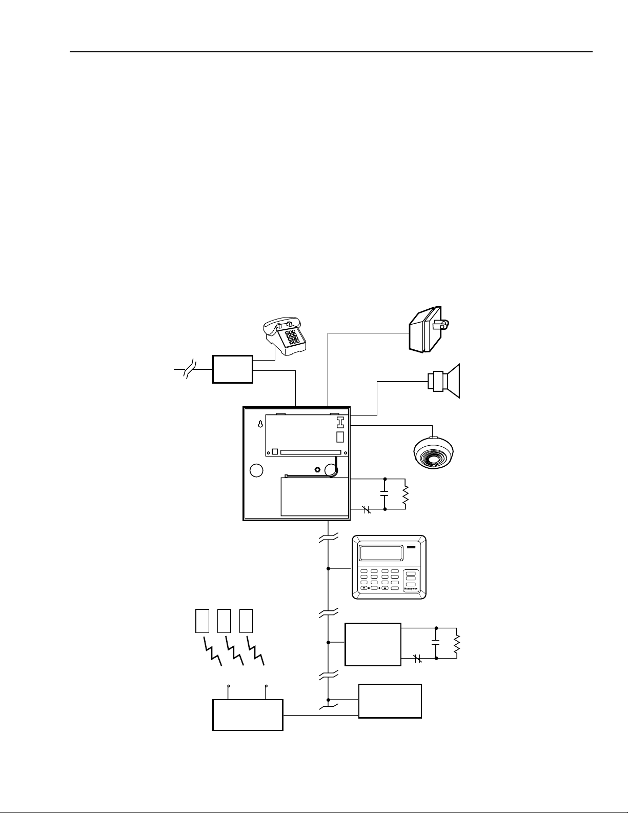
This section provides a general overview of the system
(Fig. 1) and installation and hookup instructions for the
following equipment:
1. Control Panel:
a. Enclosure.
RJ31X
b. Circuit Board.
c. Transformer.
2. Point Expansion Module.
3. RF Expansion Module.
4. RF Receiver.
5. RF Transmitter.
6. Keypad.
Control Panel
The control panel performs the main functions of the system.
The following can be found inside the control panel
enclosure:
a. Control Panel Circuit Board.
b. Batteries.
PLUG-IN
TRANSFORMER
TELCO
LINES
RF TRANSMITTERS
J1
CONTROL PANEL
BATTERY
TB1
HBUS
S1
SMOKE
DETECTOR
HARDWIRE LOOPS
1
MODES
3
2
45
6
OPTIONS
7
89
0
CANCEL
KEYPAD
POINT
EXPANSION
MODULE (PEM)
FIRE
POLICE
OK
SPECIAL
HARDWIRE LOOPS
HORN/BELL
RF EXPANSION
MODULE (RFEM)
RF RECEIVER
Fig. 1. General overview of Honeywell System 7000.
3
M10907
69-1192—1
Page 4
HONEYWELL 7000 SOLID STATE ALARM SYSTEM
Location
Locate the control panel enclosure in an area that is dry and
not subject to temperature extremes. Prolonged exposure to
temperatures below 32°F (0°C) or above 120°F (50°C) can
adversely affect the battery and some system circuits.
The location selected should be well inside the secured area
and accessible for testing and reprogramming. Allow for
routing wire runs. Locate the control panel enclosure and any
accessory equipment, such as the PEM or RFEM in:
a. Interior closet.
b. Interior wall in an untravelled area.
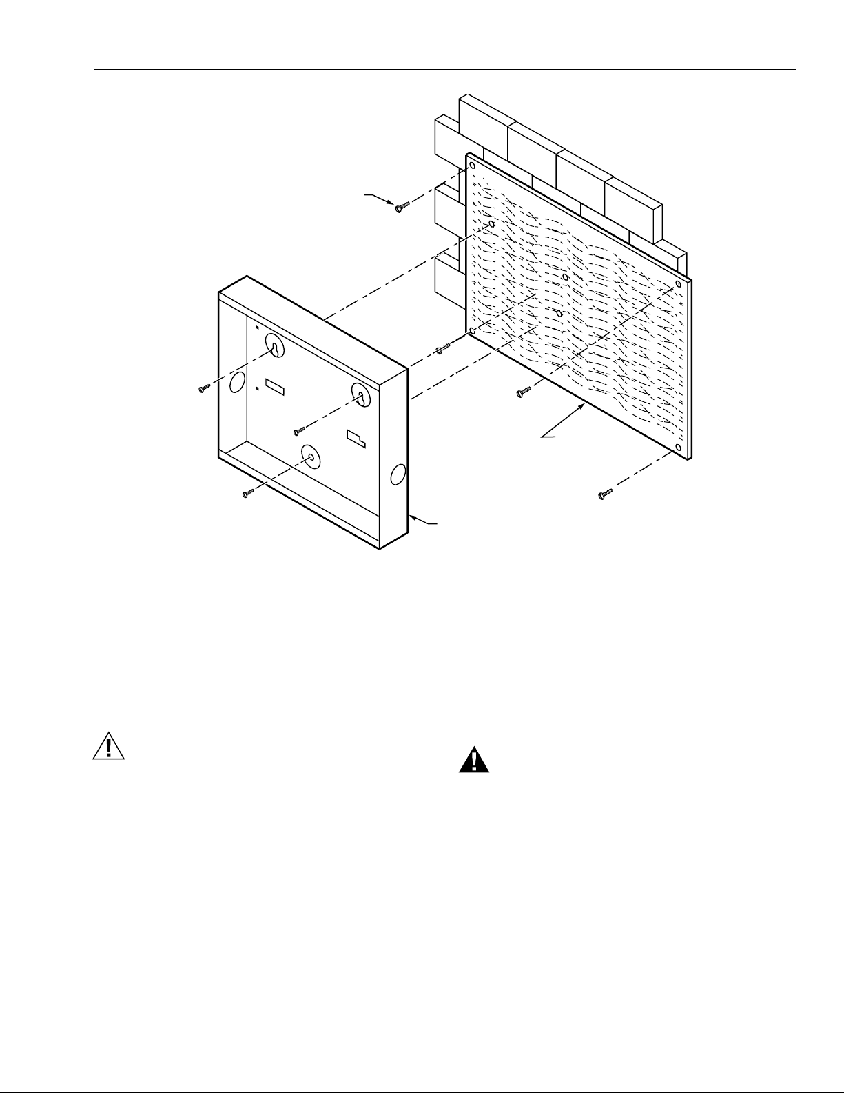
NOTE: If a cement, brick or cinderblock wall is to
be used as a mounting location, use an
appropriately sized piece of 3/4 in. (19 mm)
plywood attached to the wall with wall
anchors as a base for the system.
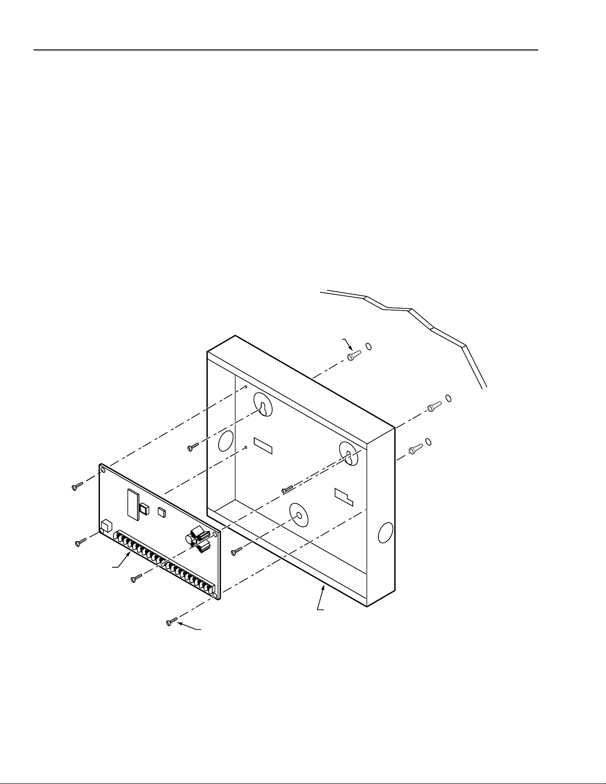
Mounting (Fig. 2 and 3)
Determine what equipment will be mounted on the wall with
the control panel box, approximate location of each device,
and probable wiring runs. This can be a rough sketch, with
approximate dimensions of the devices (see Specifications).
Based on this information, cut the 3/4 in. (19 mm) plywood, if
necessary, to the appropriate dimensions and mount the
plywood on the selected wall using wall anchors or expansion
plugs.
IMPORTANT
For RF installations, mount the RF Receiver at least
25 feet away from any other sources of RF
interference, such as garage door opener receivers.
Avoid mirrors and reflecting surfaces such as metal
heating and cooling ducts. If insufficient RF strength
is noted, move the receiver.
DRYWALL
ANCHORS
(NOT SUPPLIED)
DRYWALL
69-1192—1
CIRCUIT
BOARD
CONTROL
BOX
SUPPLIED (4)
Fig. 2. Mounting the control panel enclosure on drywall.
4
M10908
Page 5
BRICK, CONCRETE OR
CINDER BLOCK WALL
MOUNTING HARDWARE
FOR PLYWOOD
HONEYWELL 7000 SOLID STATE ALARM SYSTEM
3/4 IN. (19 MM)
PLYWOOD
Fig. 3. Mounting the control panel enclosure on plywood.
Place the empty control panel box in the correct location on
the plywood and mark the location of the mounting holes on
the plywood. If necessary, drill pilot holes at these locations.
Mount the control panel box using properly sized screw
anchors (not supplied) or other secure mounting techniques.
See Fig. 2 and 3.
CAUTION
Equipment Damage Hazard.
Static discharge can damage circuit board.
Follow ESD safety procedures when installing or
handling circuit board.
Circuit Board Installation
Mount the control panel printed circuit board in the metal
control panel box on the four standoffs and guides, using the
four screws and four lockwashers supplied.
Circuit Board Wiring
The control panel circuit board is the central wiring point for
most of the system. Connections are available for:
a. Loop wiring.
b. Smoke detector wiring.
c. Backup batteries.
CONTROL BOX
M10909
d. External bell/horn.
e. Ac connections.
f. Earth ground.
g. Telephone interface connection.
h. HBus devices (keypad, PEM, RFEM, etc.).
Wiring instructions for each of these connections or devices
are provided in the appropriate section.
WARNING
Electrical Shock Hazard
Can cause serious injury or death.
Disconnect power before wiring
General
1. Protect all wiring entering the control panel box with
strain relief and bushings.
2. Use adhesive-backed cable tie mounts and cable ties
to secure the wiring to a convenient point inside the
control panel box.
3. Use two No. 6 screws to secure the control panel box
lid after wiring is completed.
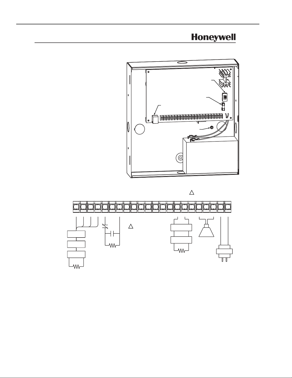
See Fig. 4 for general information on circuit board wiring.
5
69-1192—1
Page 6
HONEYWELL 7000 SOLID STATE ALARM SYSTEM
SYSTEM 7000
HOME CONTROL SYSTEM
HOME AND BUILDING CONTROL
MINNEAPOLIS, MINNESOTA
HOUSEHOLD FIRE AND BURGLARY WARNING SYSTEM.
U.L. HOME HEALTHCARE SIGNALING SYSTEM.
HOUSEHOLD BURGLARY U.L. GRADE A WHEN USED
WITH EXTERNAL AUDIBLE.
BEFORE INSTALLING, READ HONEYWELL SYSTEM 7000
INSTALLATION MANUAL, 69-1192 REV. 9/98.
BEFORE OPERATING, READ HONEYWELL SYSTEM 7000
OWNERS MANUAL.
THIS EQUIPMENT SHOULD BE INSTALLED IN
ACCORDANCE WITH CHAPTER 2 OF NFPA STANDARD 72.
NATIONAL FIRE PROTECTION ASSOCIATION,
BATTERYMARCH PARK, QUINCY, MA 02269
PRINTED INFORMATION DESCRIBING PROPER
INSTALLATION, OPERATION, TESTING, MAINTENANCE,
EVACUATION, PLANNING, AND REPAIR IS TO BE
PROVIDED WITH THIS EQUIPMENT.
THE SYSTEM IS U.L. LISTED FOR LIMITED ENERGY
INSTALLATIONS PER NEC ARTICLE 760.
USE ONLY U.L. RECOGNIZED LIMITED ENERGY CABLE.
TEST SYSTEM AT LEAST ONCE A WEEK WITH AC OFF.
SYSTEM SHOULD BE CHECKED BY A QUALIFIED
TECHNICIAN AT LEAST EVERY THREE YEARS.
STANDBY BATTERY/BATTERIES SHOULD BE REPLACED
EVERY FIVE YEARS.
DISCONNECT AC LINES AND TELEPHONE WIRES
BEFORE SERVICING.
WARNING:
OWNERS INSTRUCTION NOTICE NOT TO BE
REMOVED BY ANYONE EXCEPT OCCUPANT.
WARNING: LEAVING THE POWER SWITCH
IN THE OFF POSITION RENDERS THE SYSTEM
7000 CONTROL PANEL INOPERABLE.
WARNING: FOR CONTINUED PROTECTION
AGAINST FIRE, REPLACE FUSE WITH SAME
J1
TYPE AND RATING (AGA 2)
TELCO LINE COUPLER CORD TO RJ31X.
CONNECT PC PROGRAMMER HERE FOR LOCAL
PROGRAMMING.
CONNECT TO EARTH GROUND
STANDBY BATTERY
MINIMUM REQUIREMENTS: 12 VDC, 7 AH
REFERENCE PART NUMBER 32002215-001
REPLACE BATTERY EVERY 5 YEARS.
SYSTEM SUPPLIES 4 TO 24 HR. EMERGENCY
STANDBY CAPACITY. 24 HOURS REQUIRED
FOR FIRE PROTECTION. SEE INSTALLATION
MANUAL 69-1192 REV 9/98 FOR EQUIPMENT
AND BATTERY CONFIGURATIONS.
S 1
AC
1
HBUS-
HBUS+
COM
+13.8 VDC
P1
P2
COM
P3
P4
COM
P5
P6
COM
P7
P8-
P8+
AUX
TB 1
+
+
+
+
+
+
+
+
+
+
+
+
+
+
+
+
+
1
2
3
4
5
6
7
8
9
10
11
12
13
14
15
16
17
BLK
YEL
GRN
HSP
PEM
RFEM
EOLR
120Ω 5% 1/4W
END OF LINE RESISTOR
CONNECTED ACROSS THE
HBUS+ AND HBUS–
CONTACTS OF LAST (END)
DEVICE CONNECTED TO
THE HBUS CIRCUIT
RED
NC
NO
EOLR
3.3K 5% 1/4W
TYPICAL FOR
POINTS P1 TO P7
END-OF-LINE
RESISTOR MUST BE
AT END OF CONTACT.
AUXILIARY OUTPUT,
1
PROGRAMMABLE
VOFF = 25V MAX (FLOAT)
VON = 1.1V MAX
ISINK = 100 mA
–
SMOKE DETECTOR
–
SMOKE DETECTOR
–
5.1K 5% 1/4W
MAXIMUM OF 10 2-WIRE
SMOKE DETECTORS. REFER TO
INSTALLATION INSTRUCTIONS
69-1192 FOR A LIST OF
APPROVED DETECTORS.
SMOKE DETECTOR COMPATIBILITY
IDENTIFIER IS 7K8.
P8 MAY BE WIRED FOR 2-WIRE FIRE
OR 4-WIRE FIRE OR BURGLARY.
2-WIRE FIRE IS SHOWN. FOR
4-WIRE FIRE AND BURGLARY
WIRING, SEE INSTALLATION
INSTRUCTIONS.
EOLR
+
+
+
Fig. 4. Control panel wiring, showing TB1 and general physical layout.
HORN
COM
+
+
18
19
–
BELL / HORN
12 VDC,
1 AMP MAX.
PLUG-IN TRANSFORMER
+13.8 VDC
AC IN
AC IN
+
+
+
20
21
22
+
PART NO.: 32002143-001
INPUT 120 VAC, 60HZ
OUTPUT: 24 VAC, 50 VA
CLASS 2
DO NOT CONNECT AC
TRANSFORMER TO A
SWITCH CONTROLLED
OUTLET.
97-5790 REV.
M10910
69-1192—1
6
Page 7
HONEYWELL 7000 SOLID STATE ALARM SYSTEM
Connect loop wiring but do not run wiring within 12 in. (305
mm) of house ac wiring.
IMPORTANT
Do not run any wires or cabling behind or across the
control panel printed circuit board.
Point Expansion Module (PEM) Installation
The PEM provides additional hardwire points for the
Honeywell 7000 System and can be used in place of, or in
conjunction with, the RF transmitters and receivers. The PEM
MOUNTING SLOTS
ON BACK OF RFEM
can support normally open (NO) or normally closed (NC)
sensor contacts. The PEM has eight hardwire point
connections and two relay output connections.
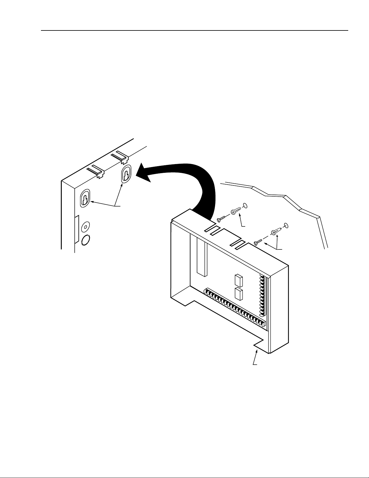
Mount the PEM plastic box within 250 feet (76 meters) of the
control panel if using 22 AWG wire or 500 feet (152 meters) if
using 18 AWG wire.
Remove the PEM circuit board from the PEM plastic box (if
installed) and use the PEM plastic box to mark the mounting
screw locations on the wall or plywood. Use two screws (not
supplied) to mount the PEM plastic box. Insert the PEM
circuit board into the PEM plastic box. See Fig. 5.
DRYWALL
OR PLYWOOD
ANCHORS
Fig. 5. Installing the PEM plastic box.
PEM (COVER
REMOVED)
NOT
SUPPLIED
M10912
7
69-1192—1
Page 8
HONEYWELL 7000 SOLID STATE ALARM SYSTEM
PEM Wiring
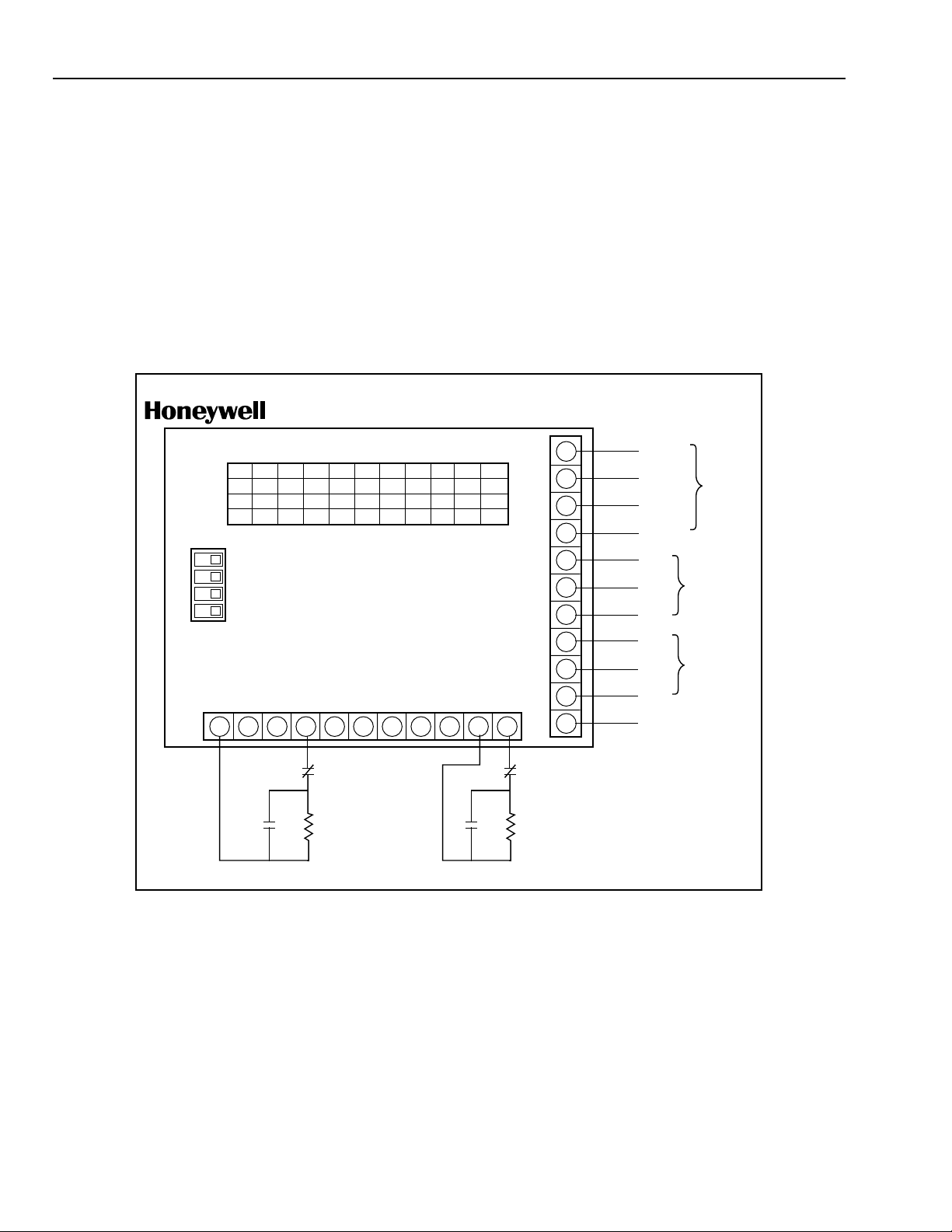
1. Use four-conductor AK4500A cable to connect the PEM
to other HBus devices.
2. Connect the PEM wires to the control panel according
to the wiring diagram with the unit. See Fig. 6.
Each PEM has a unique, four digit, address. Fig. 6 lists the
PEM address number and switch settings. The Honeywell
7000 System can support up to 11 PEM.
GOLDEN VALLEY, MINN.
P2
PEM ADDRESS #
P3
P4
NC
EOLR
ALL EOLR =
3.3K 1/4W 5%
GND
P5
12 3 456 7891011
1
ON ON ON ON ON ON ON ON
S1
2
ON ON ON ON OFF OFF OFF OFF
ON ON OFF OFF ON ON OFF OFF
3
ON OFF ON OFF OFF OFF ON OFF
4
S1
OFF ON
1
2
3
4
TB1
S1 SETS PEM ADDRESS #
S1 SHOWN SET FOR ADDRESS #1
MAXIMUM OF 11 PEMs ON A SYSTEM
GND
P1
1 2 3 4 5 6 7 8 9 10 11
NO
TYP WIRING: POINT 1-7 WIRING: POINT 8
RFEM Installation
The RFEM provides additional rf protection points for the
Honeywell 7000 System. Only one RFEM can be used per
system.
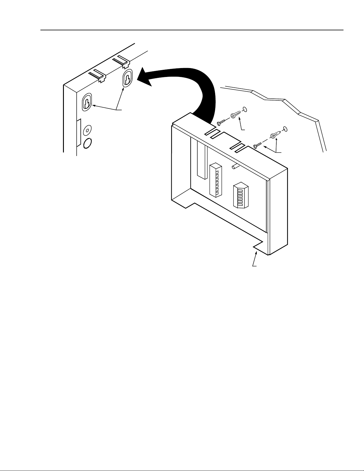
Mount the RFEM plastic box within 250 feet (76 meters) of
the control panel if using 22 AWG wire or 500 feet (152
meters) if using 18 AWG wire.
Remove the RFEM circuit board from the RFEM plastic box
(if installed) and use the RFEM plastic box to mark the
mounting screw locations on the wall or plywood. Use two
screws to mount the RFEM plastic box. Insert the RFEM
circuit board into the RFEM plastic box. See Fig. 7.
SYSTEM 7000
PEM
OFF OFF OFF
ON ON ON
ON ON OFF
ON OFF ON
P6
P7
NO
P8–
SEE INSTALLATION MANUAL
BLK
11
RED
10
GRN
9
YEL
8
7
6
5
4
3
NC
EOLR
TB2
2
1
RELAY:
CURRENT DRAIN ≤ 40 mA
CONTACT RATING:
RESISTIVE
2A @ 30 VDC
0.4A @ 30 VAC
INDUCTIVE
1A @ 30 VDC
0.2A @ 30 VAC
LABEL 2480341 REV B
P8+
GND
+13.8 VDC
HBUS–
HBUS+
NO
NC
C
NO
NC
C
GND
TO
CONTROL
PANEL
RELAY 1
RELAY 2
69-1192—1
Fig. 6. PEM wiring diagram.
8
M10902
Page 9
MOUNTING SLOTS
ON BACK OF RFEM
HONEYWELL 7000 SOLID STATE ALARM SYSTEM
DRYWALL
OR PLYWOOD
ANCHORS
NOT
SUPPLIED
Fig. 7. Installing the RFEM.
RFEM Wiring
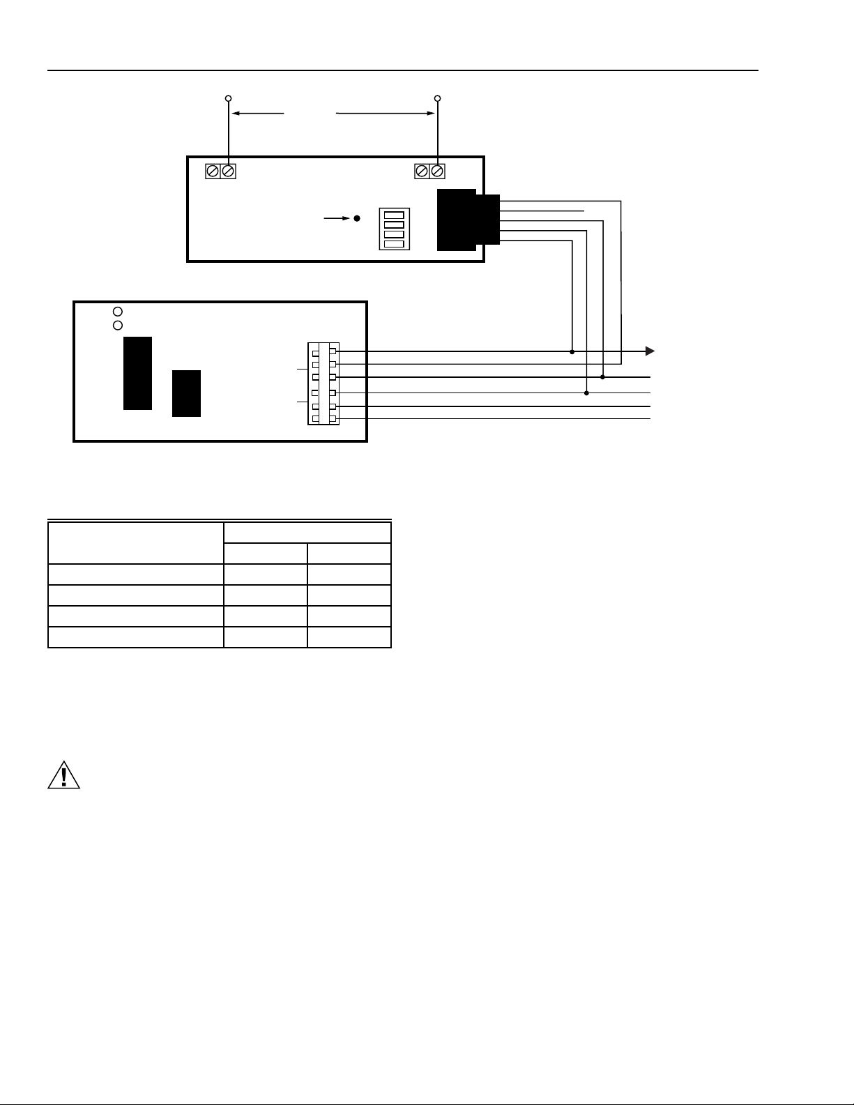
1. Use four-conductor AK4500A cable to connect the PEM
to other HBus devices.
2. Connect the RFEM wires to the control panel according
to the wiring diagram with the unit. See Fig. 8.
RF Receiver Installation
The RF Receiver receives messages from the RF
Transmitters, demodulates and transfers the data to the
RFEM for decoding. A maximum of two receivers can be
connected to an RFEM.
Perform the following steps:
1. Remove the cover from the RF Receiver (use a thinbladed screwdriver to release the cover).
RFEM (COVER
REMOVED)
M10911
2. Place the open receiver on the wall in the desired
location, leaving room for the two antennas.
3. Use a pencil or other marking device to mark the two
screw locations for the receiver.
4. Install the two screws (not supplied), leaving enough
room to hang the receiver on the screws.
5. Install the antennas in the slots as shown in Fig. 9. The
antennas go in the right-hand slot of each set.
6. Set the receiver switches as shown in Table 1.
9
69-1192—1
Page 10
HONEYWELL 7000 SOLID STATE ALARM SYSTEM
ANTENNAE
RF RECEIVER
INTERFERENCE
INDICATOR
R
PANEL
G
RF
RFEM
6
DATA
5
4
3
POWER
2
1
HBUS
TB1
Fig. 8. Connecting the RFEM to the RF Receiver.
ON - OFF
4
3
2
1
DATA I N
DATA OUT
+12V
(GND)
HBUS (+)
HBUS (–)
GREEN
YELLOW
RED
BLACK
YELLOW
GREEN
YELLOW
BLUE
RED
BLACK
GREEN
RED
BLACK
YELLOW
GREEN
TO SYSTEM 7000
CONTROL PANEL
HBUS TERMINALS
M10903
Table 1. RF Receiver switch settings.
Receiver
Switch Position 1 2
4ONOff
3 OFF ON
2 OFF OFF
1----
RF Receiver Wiring
IMPORTANT
No two receivers can have the same address
settings. Only address 1 or 2 can be used.
CAUTION
Equipment Damage Hazard.
Incorrect connections can damage hardware.
Wire the RF Receiver according to Fig. 8.
Keypad Installation (Fig. 9)
The keypad is used by the homeowner to operate the
Honeywell 7000 System. The two-line display provides
information about what is happening and the locations of any
problems. The display will automatically prompt the user with
help instructions after eight seconds of inactivity.
Locate the keypad no further than 250 feet from the control
panel if using 22 AWG cable or 500 feet if using 18 AWG
cable. Do not route keypad wiring parallel to ac wiring or
within 12 in. of ac wiring.
NOTE: A maximum of 11 keypads can be installed
on one Honeywell 7000 System.The control
panel can supply power for up to four
keypads. Additional keypads must be
powered by an external 12V power source
with backup batteries.
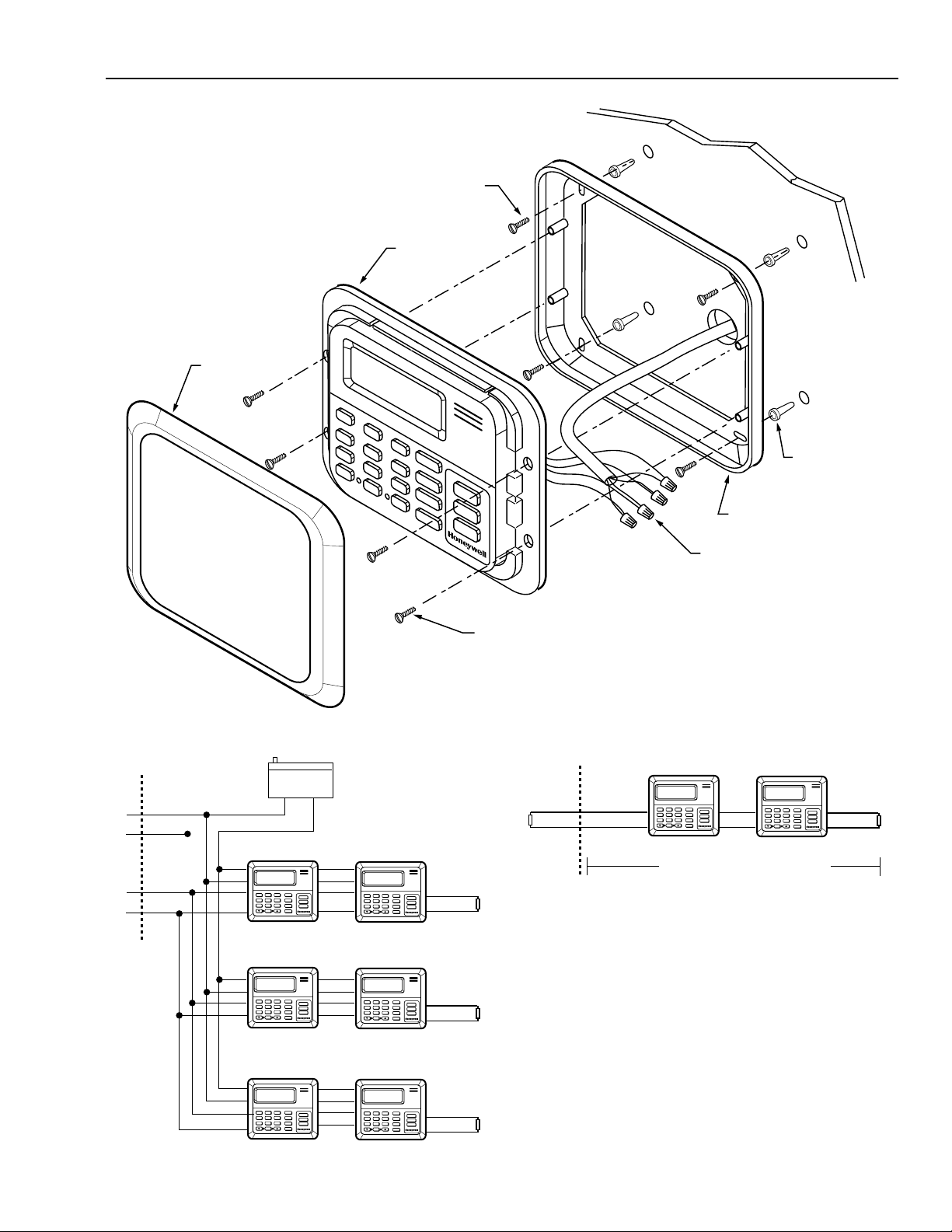
A standard plastic base is provided. To mount the keypad:
1. Secure the base to the wall.
2. Attach the wires to the keypad.
3. Fasten the keypad to the base.
4. Attach the trim ring to the keypad.
Keypad Wiring
Honeywell 7000 System keypads are connected to each
other and to the control panel via the HBus. Follow these
wiring practices:
1. Use four-conductor AK4500A cable to connect the
keypad to other HBus devices.
2. Keep maximum distance for the data line from the
control panel to the farthest device under 3000 feet.
3. Keep the maximum distance from the power source to
the farthest keypad under 250 feet.
IMPORTANT
No more than four keypads can share the same
power wiring pair.
NOTE: Separate power sources are required when
the distance exceeds 250 feet. Use Altronix
Model AIL100 or ALARM SAF Model PS-FMC12/10-BFS/UL 3/4A power supplies when ULapproved equipment is required.
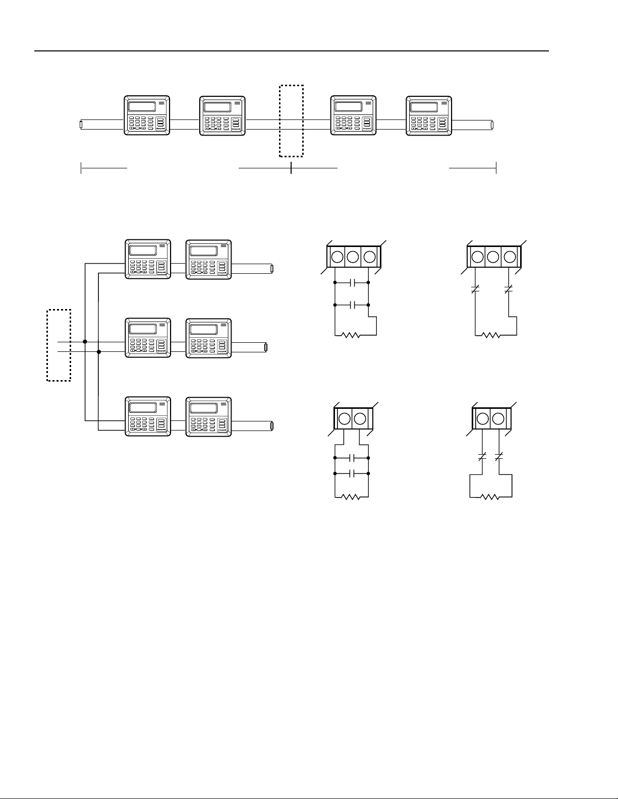
4. Always use 120 ohm end-of-line resistors (provided
with keypad) to terminate the ends of the HBus line as
shown in Fig. 10 through 13.
69-1192—1
10
Page 11
HONEYWELL 7000 SOLID STATE ALARM SYSTEM
xxxxx
xxxx
xxxxx
xxxxx
xxxxx
xxxxx
xxxxx
1
2
3
45
6
7
89
0
xxxxx
xxxx
xxxxx
xxxxx
xxxxx
xxxxx
xxxxx
1
2
3
45
6
7
89
0
M10894
120 OHM
120 OHM
KEYPAD KEYPAD
TB-1
1
2
MAXIMUM SIGNAL DISTANCE 3000 FT
SYSTEM 7000
CONTROL
TRIM RING
MOUNTING
SCREWS (4)
TOUCHPAD
SCREWS (4)
WALL
MOUNTING
BASE
FOUR WIRES
CONNECT TO HBUS
SCREW
ANCHORS (4)
M10604A
POWER
SOURCE
TB-1
CMN
(-) (+)
(+) 13.8V
KEYPAD KEYPAD
HBUS (-)
HBUS (+)
1
45
7
2
89
0
xxxxx
3
xxxxx
6
xxxx
xxxxx
xxxxx
xxxxx
xxxxx
KEYPAD KEYPAD
1
xxxxx
3
2
xxxxx
45
6
xxxx
xxxxx
7
89
xxxxx
xxxxx
0
xxxxx
KEYPAD KEYPAD
Fig. 10. External keyboard power wiring.
1
45
7
2
89
0
xxxxx
3
xxxxx
6
xxxx
xxxxx
xxxxx
xxxxx
xxxxx
Fig. 9. Standard surface mount of keypad.
1
xxxxx
3
2
xxxxx
45
6
xxxx
xxxxx
7
89
xxxxx
xxxxx
0
120 OHM
xxxxx
Fig. 11. Daisy chain HBus wiring.
5. Connect the keypad cable to the control panel four-
conductor cable using wirenuts.
6. Use adhesive-backed cable tie mounts to secure the
1
45
7
2
89
0
xxxxx
3
xxxxx
6
xxxx
xxxxx
xxxxx
xxxxx
xxxxx
120 OHM
keypad cable to the back of the keypad for strain relief.
NOTE: If power to the keypad is lost, the bell will chirp as an
audible supervision signal.
1
xxxxx
3
2
xxxxx
45
6
xxxx
xxxxx
7
89
xxxxx
xxxxx
0
120 OHM
xxxxx
M10893
11
69-1192—1
Page 12
HONEYWELL 7000 SOLID STATE ALARM SYSTEM
N
N
KEYPAD KEYPAD
SYSTEM 7000
CONTROL
TB-1
KEYPAD KEYPAD
120 OHM
45
7
2
89
0
xxxxx
6
xxxx
xxxxx
xxxxx
xxxxx
xxxxx
1
45
7
2
89
0
xxxxx
3
xxxxx
6
xxxx
xxxxx
xxxxx
xxxxx
xxxxx
1
xxxxx
3
MAXIMUM SIGNAL DISTANCE 3000 FT MAXIMUM SIGNAL DISTANCE 3000 FT
Fig. 12. Dual branch HBus wiring.
KEYPAD KEYPAD
1
xxxxx
3
SYSTEM 7000
CONTROL
TB-1
1
2
xxxxx
45
6
xxxx
xxxxx
7
89
xxxxx
xxxxx
0
xxxxx
KEYPAD KEYPAD
1
xxxxx
3
2
xxxxx
45
6
xxxx
xxxxx
7
89
xxxxx
xxxxx
0
xxxxx
1
45
7
1
45
7
2
89
0
2
89
0
xxxxx
3
xxxxx
6
xxxx
xxxxx
xxxxx
xxxxx
xxxxx
xxxxx
xxxxx
120 OHM
120 OHM
xxxxx
xxxxx
3
6
xxxx
xxxxx
xxxxx
2
KEYPAD KEYPAD
1
xxxxx
3
45
7
2
89
0
xxxxx
6
xxxx
xxxxx
xxxxx
xxxxx
xxxxx
1
45
7
2
89
0
xxxxx
3
xxxxx
6
xxxx
xxxxx
xxxxx
xxxxx
xxxxx
120 OHM
M10896
Fig. 13. Star HBus wiring.
Hardwired Detection Circuits
The Honeywell 7000 System control panel and each PEM
has eight fully supervised hardwired input loops that can be
used for zoning groups of sensors or identifying individual
points of protection. These input loops can be programmed to
respond as the point types listed in Table 2.
Burglary Circuit Wiring
1
1
45
7
2
89
0
2
P1
TB1
5 6 7
N.O.
N.O.
EOLR
3.3K 5% 1/4W
NORMALLY OPEN CONTACTS
HARDWIRE LOOP WIRING P1 THROUGH P7
P8 –
TB1
15 16
EOLR
5.1K 5% 1/4W
NORMALLY OPEN CONTACTS
P8 HARDWIRE LOOP WIRING FOR BURGLARY
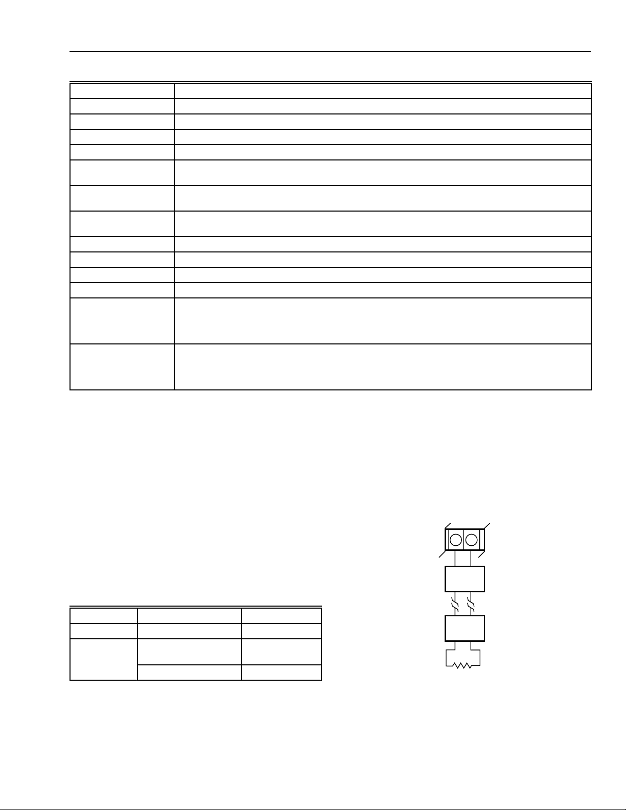
Fig. 14. Terminal Block TB1 hardwire loops.
xxxxx
3
xxxxx
6
xxxx
xxxxx
xxxxx
xxxxx
xxxxx
1
45
7
2
89
0
xxxxx
3
xxxxx
6
xxxx
xxxxx
xxxxx
xxxxx
xxxxx
120 OHM
M10895
P2
CM
TB1
N.C.
P1
P2
5 6 7
CM
N.C.
EOLR
3.3K 5% 1/4W
NORMALLY CLOSED CONTACTS
P8 +
N.O.
TB1
N.C.
P8 –
15 16
P8 +
N.C.
N.O.
EOLR
5.1K 5% 1/4W
NORMALLY CLOSED CONTACTS
(PERFERRED)
M10898
1. Use only UL-listed switches and sensors.
2. Use UL-listed wire, 22 AWG minimum.
3. Loop lengths are not to exceed 1000 feet.
4. Each circuit must be terminate with a 3.3K ohm,
1/4 watt EOLR (provided).
5. Make all connections according to the loop diagrams
that follow.
6. Program loops for type as well as NC or NO contact
operation.
69-1192—1
12
Page 13
HONEYWELL 7000 SOLID STATE ALARM SYSTEM
Table 2. Input loop point types.
Type Description
Perimeter A burglary circuit that instantly alarms on cross or break when violated.
Entry/Exit 1 A burglary circuit that signals a warning for time period 1 before alarming.
Entry/Exit 2 A burglary circuit that signals a warning for time period 2 before alarming.
Interior A burglary circuit that is ignored during the exit and entry delay periods.
Interior Delay A burglary circuit that signals a warning for time period 2 when violated and is ignored during the
Tamper A burglary circuit that is always on. Violation of this point will be reported but the local audible alarm
Police A burglary alarm that instantly alarms on cross or break when violated. The audible alarm is
Fire A fire circuit that instantly alarms on cross and signals a trouble on break.
Medical/Special A circuit that instantly alarms with a separate audible sound.
Equipment Supervisory A circuit that instantly alarms with a separate audible sound.
Strategy (Mode): An input that invokes a specified security mode.
Smart A burglary point or zone that can be part of the complete security as well as operated separately by
Pool Violation of the point causes the keypad audible to sound throughout the house for 30 seconds
normal exit and entry delay periods.
can be optioned to be silenced.
selectable separately.
Special Protection Modes. Used for protecting an isolated door (to let pets out, for example), as well
as protection for the home office, bar, gun rack, workshop, etc. This point alarms instantly when
occupants are away and sounds a warning for time period 2 when persons are at home.
when occupants are home and the keypads, bell or siren to sound for 30 seconds when occupants
are away. Requires a separate device to be installed to delay the audible on entry or briefly bypass
the audible on exit by an adult. Available from Safeguard Innovations: (612) 784-7786.
Fire Circuits
The Honeywell 7000 System directly supports certain
specified two-wire fire detectors. Four-wire detectors require
special wiring and programming arrangements for resetting
smoke detectors.
Two-Wire Smoke Detector Circuit
The Honeywell 7000 System directly supports one two-wire
fire circuit (loop 8 on the control panel). Use the following
approved smoke detector models and refer Fire Marshals to
the compatibility ID shown in Table 3. The compatability ID for
the Honeywell 7000 System is 7K8.
Table 3. Two-wire smoke detectors and compatibility ID.
Manufacturer Model Compatibility ID
Sentrol 429A, 429AT S10A
Detection
Systems
DS250, DS250TH,
DS50HD Detectors
B
MB2W, MB2WL Bases A
Two-Wire Fire Circuit Installation
1. Install smoke and heat detectors in accordance with
manufacturer instructions.
2. Use UL-listed 18 AWG energy limited cable (Signal
Cable Co. No. 98804, for example) to wire a maximum
of 10 two-wire smoke detectors within 200 feet of the
control panel.
3. Attach the 5.1 Kilohm, 1/4 watt EOLR (provided) at the
last smoke detector.
4. Wire detectors as shown in Fig. 15.
P8 –
P8 +
TB1
15 16
+
–
SMOKE
DETECTOR
+
–
+
MAXIMUM OF 10
SMOKE DETECTORS
2 WIRE
–
SMOKE
DETECTOR
+
–
EOLR
5.1 K 5% 1.4W
M10900
Fig. 15. Wiring diagram for two-wire smoke detectors.
13
69-1192—1
Page 14
HONEYWELL 7000 SOLID STATE ALARM SYSTEM
Four-Wire Smoke Detector Circuit
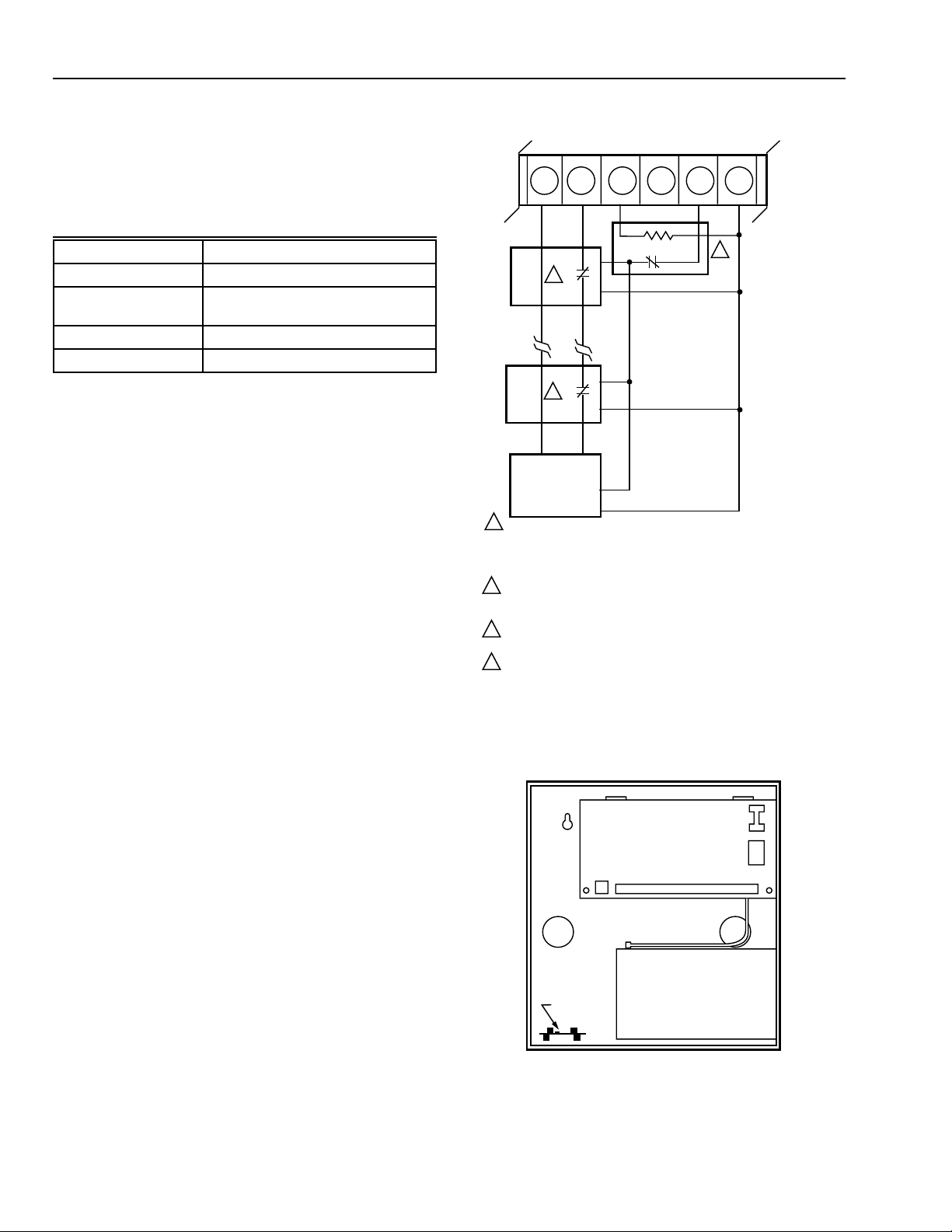
Loop 8 of the Honeywell 7000 System control panel can
supervise four-wire smoke detectors with the wiring
arrangements shown in Fig. 19. Use the approved equipment
listed in Table 4.
Table 4. Approved four-wire smoke detection devices.
Manufacturer Model
Sentrol 449CT Detector
Detection Systems DS250, DS240TH Detectors;
MB4W, MB4WL Bases
Honeywell EM100 End-of-Line Module
AlarmSaf Relay AS/BRK-624 Reset Relay
Four-Wire Circuit Installation
1. Use 18 AWG FPL cable such as Honeywell
AK4704ARE.
2. Secure the smoke alarm reset relay module in the
bottom of the Honeywell 7000 System metal box as
shown in Fig. 19 with double-sided tape (provided).
3. Install smoke and heat detectors in accordance with
manufacturer instructions.
4. Wire the circuit as shown in Fig. 16.
P8 –
TB1
15 16 17 18 19
COM
1
COM
SMOKE
DETECTOR
COM NO
1
COM NO
SMOKE
DETECTOR
VIOLET
2
HONEYWELL EM1000
P8 +
NO
NO
RED/
WHITE
BLACK
RED
–
+
–
+
AUX OUT
AS/RBK-624
BELL
4-WIRE SMOKE DETECTOR HOOK-UP
COM
+13.8 VDC
20
3
IMPORTANT
Do not exceed the +13.8V total current draw with all
detectors in alarm.
5. Connect the End-Of-Line Module at the last smoke
detector. All wire leads must be insulated with a
minimum of 0.013 in. insulation or wire nuts that cover
all exposed leads.
6. Make sure that all wire is contained within the base of
the smoke detector.
7. Program a Special Mode with the name FIRE RESET
to operate the fire reset relay from a programmable
output.
Four-Wire Circuit Reset Operation (Fig. 17).
Reset four-wire smoke detectors from the keypad by
entering the disarm code and pressing the FIRE
RESET mode numeric key.
The reset period is approximately 60 seconds, after
which the Fire loop is returned to service. During the
60 seconds, the power is removed and the Fire loop
is disabled. At the end of the 60 seconds, the alarm
condition will repeat if the detector still detects
smoke.
1
#4-WIRE SMOKE DETECTORS:
SENTORL ESL 449CT OR
DETECTION SYSTEMS INC. DS250 SENSOR AND MB4W BASE
2
END-OF-LINE MODULE:
HONEYWELL EM1000
3
SMOKE RESET RELAY:
ALARMSAF RELAY (PART NO. AS/RBK-624) IS REQUIRED AND MUST
BE PROCURED SEPARATELY FOR PROPER OPERATION OF THE
FOUR-WIRE SMOKE DETECTOR SYSTEM.
M10901
Fig. 16. Wiring diagram for four-wire hardwired smoke
detectors.
S1
AS/RBK-624
J1
TB1
BATTERY
69-1192—1
M10904
Fig. 17. Installation of smoke alarm reset relay.
14
Page 15

HONEYWELL 7000 SOLID STATE ALARM SYSTEM
RF Wireless Sensors
The Honeywell 7000 System will work with a broad line of
Series 5800 RF security and fire sensors when connected to
a 5800HK Receiver/RFEM. The system first must be
programmed to recognize the unique serial identification code
of each sensor and to bind these codes to logical 7000
System input point numbers. After the RFEM has been
connected to the HBus and a 5881H Receiver connected to
the RFEM, proceed as follows:
1. Specify the number of receivers present on the site in
the programmer database for this site (either one or two
under the UNITS: ACCOUNT INFO menu). This will
enable further programming of RF points and tell the
system to regularly poll and thereby supervise the
presence of the receivers.
2. Examine all of the RF transmitters and note the serial
numbers stamped under the bar codes. Ignore the
alpha letter (date code) and program the numeric serial
numbers in the POINTS: HOW CONNECTED menu.
3. Identify the transmitter type and select how the inputs
(loops) are used from Table 5.
NOTE: Transmitters may have up to four inputs that
can be treated as independent points by the
system.
4. Place the system into RF TEST (OPTION 8 from the
keypad). The RF receiver runs at 50 percent sensitivity
to assure adequate range for future changes to the
environment. The keypad beeps every time a
transmitter is operated and also records the operation
in the event log for later review by the installer.
5. Mount each sensor as noted in the instructions with
each device.
6. Operate each sensor several times, verifying each time
that the sound is heard at the keypads.
7. Turn the RF TEST option off after all sensors are
installed and operated.
8. Check the event log record for indications of correct
operation of each sensor.
NOTE: In the event of any RF transmission problems:
a. Move sensors away from any metal that could
obstruct RF signaling.
b. Move the transmitters two to three inches to get
them away from multi-path nulls.
Outputs
Honeywell 7000 System supports two solid state outputs on
the main control panel and two relay outputs on each PEM.
All but the HORN output are fully programmable for
maintained or momentary operation. They can be:
a. activated by events (Burglar Alarm, Fire Alarm,
Equipment Alarm, Police Alarm, Medical/Special Alarm,
System Ready, On Watch, Interior Siren, Exterior
Siren);
b. be programmed to follow the activities of any security
points, and
c. be operated by selected modes.
Control Panel Output Wiring
1. Connect the external siren to the HORN output. Use
sounding devices that draw less than 950 mA.
2. Wire a secondary output device drawing no more than
100 mA to the AUX output. When operating a relay,
connect a recirculating diode across the relay coil.
PEM Output Wiring
1. Each device has two programmable outputs that are
form C relay configurations (a NC as well as NO
contact with a shared common side).
2. Each contact is rated for operating a maximum of 1A for
a 24V load. Use the contact to drive a relay with
contacts rated for higher loads and power when
required.
External Bell/Horn Installation
The HORN output can power a 950 mA bell or siren
with a built-in driver. The control panel supervises
the wiring to the sounding device for a wire break or
ground condition. In the event of a wiring fault,
HORN FAILURE is displayed on the keypad screen.
This condition must be acknowledged by entering a
valid passcode to silence the keypad audible. When
UL-approved equipment is required, use the devices
listed in Table 6.
Table 5. RF wireless sensors.
Device Description Loop 1 Loop 2 Loop 3 Loop 4 RF Type
5801 Tabletop Transmitter Lower Right Upper Right UpperLeft Lower Left UR
5802 Panic Button Button —- —- —- UR
5804 Wireless Key (4) Lower Right Upper Right Upper Left Lower Left BR
5808 Wireless Smoke Detector Detector Alarm —- —- —- RF
5816NM 2-Point Door/Window Termnals Reed Switch —- Tamper RF
5817 3-Point Door/Window TB1 1-2 TB1 3-4 TB1 5-6 Tamper RF
5818 Recessed Door/Window Reed Switch —- —- —- RF
5849 Glass Break Detector Sound —- —- Tamper RF
5890 Passive Infrared Detector IR Detector Walk Test —- Tamper RF
15
69-1192—1
Page 16
HONEYWELL 7000 SOLID STATE ALARM SYSTEM
C
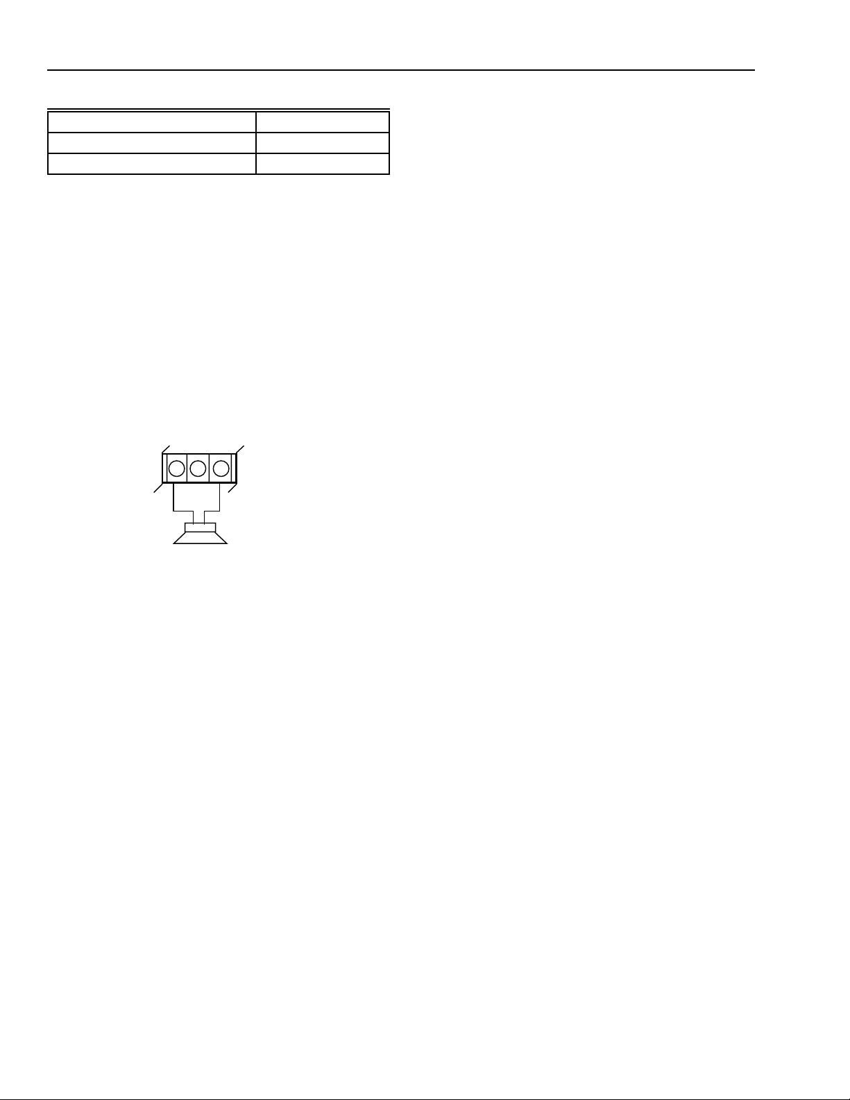
Table 6. Approved external sound devices.
Siren Manufacturer Model
Ademco 747UL
Revere R44SSD
The following are general instructions for the bell or
horn installation. Follow the instructions specified for
the device to be used.
1. Use UL-listed 18 AWG wire.
2. Locate bell or horn within 200 ft of panel.
3. Install bell or horn following manufacturer instructions.
4. Connect a 3.3K ohm, 1/4 watt, resistor across HORN
terminal (TB1-18) and +13.8V (TB1-20) when no
external sounding device is used.
For tamper-protection of a bell or siren enclosure wire, wire
two leads from the external device NC tamper switch contacts
to a loop programmed as a tamper loop.
BELL
CMN
+13.8 VD
TB1
18 19 20
–+
Plug one end into J1 on the control panel board and the other
end into the RJ-31X Phone Terminal Block. See Fig. 19.
Transformer Installation
The Honeywell 7000 System is powered by a 120 Vac to
24 Vac, 50A, plug-in transformer. Install the transformer as
follows:
1. Locate the control panel within 25 ft of a non-switched
power receptacle.
2. Make sure that S1, the control panel power switch, is
off.
3. Use UL-listed two-conductor twisted pair 18 AWG wire
to connect the transformer to the AC IN connectors
(TB1-21 and TB1-22) on the control panel.
4. Secure the transformer to the outlet with the faceplate
screw.
Battery Installation
The control panel has room for two 7 Ampere-Hour (AH)
batteries in the enclosure and can recharge up to 28AH of
battery capacity when longer standby is required. The system
supervises for the presence of battery and tests the operation
of the battery and charging system every two hours when ac
is present (every three minutes when ac is lost). A
disconnected, shorted or defective battery will indicate SYS
LOW BATTERY on the keypad display and must be
acknowledged by the user to silence the trouble audible.
Replace defective batteries.
BELL/HORN
12 VDC @ 1 AMP MAX
M10899
Fig. 18. External bell/horn hookup diagram.
NOTE: To meet CSFM requirements, the fire system must
use an ADEMCO Model 747UL Siren only.
Telephone Wiring
This connection is required for monitored installations or
whenever remote programming is desired. Proceed as
follows:
1. Install the RJ-31X Phone Terminal Block within 25 ft of
the control panel.
2. Use UL-listed 26 AWG wire or larger.
3. Connect in accordance with Fig. 11 and 12.
4. Program the Digital Receiver telephone number in the
Honeywell 7000 System panel only after all installation
and checkout has been completed, to avoid jamming
the panel buffer with repeated retries.
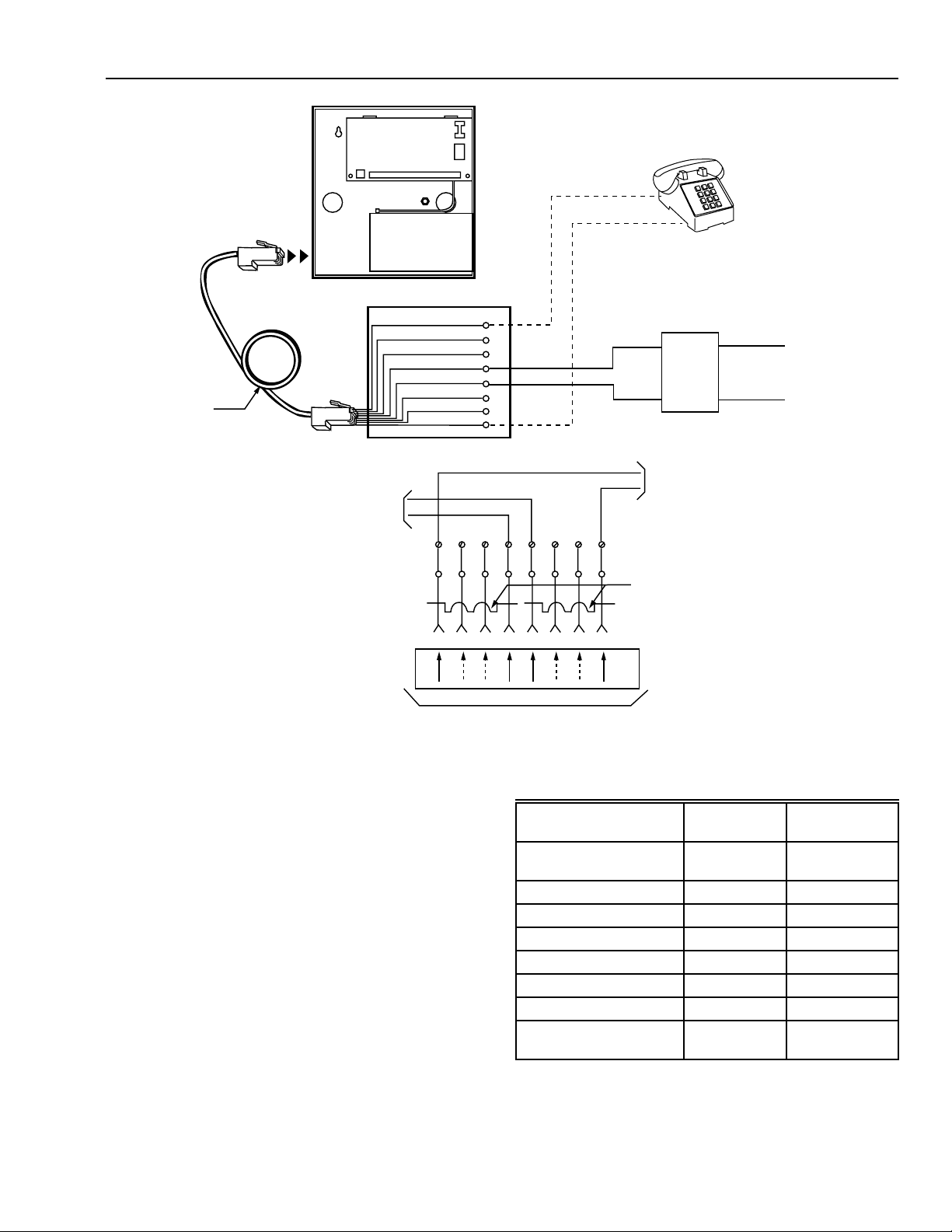
Modular Telephone Coupler Cord
This standard eight-conductor telephone cord is used to
connect the Honeywell 7000 System to the RJ-31X Phone
Terminal Block. See Fig. 19.
If not provided by the phone company, install the RF-31X
Phone Terminal Block in accordance with the wiring diagrams
in Fig. 19.
Install the battery as follows:
1. Use 12 volt, rechargeable, gel-cell batteries rated for
the appropriate AH necessary to deliver the prescribed
standby for the installation. See the battery table and
load calculations that follow.
2. Make sure that S1, the control panel power switch, is
off.
3. Connect the control panel leads to the appropriate
battery terminals.
IMPORTANT
Observe battery polarity (red to positive [+], black to
negative [-]).
Standby Battery
The Honeywell 7000 System uses 7 AH gel-cell lead-acid
batteries for standby power. UL installations require 24 hour
of standby power. This section shows how to determine the
number of batteries needed for the system being installed.
One or two batteries can be installed in the system control
panel enclosure. If three or four batteries are needed, they
must be installed in a separate enclosure. The wiring
between these remote batteries and the control panel must
be enclosed in electrical conduit.
69-1192—1
16
Page 17
HONEYWELL 7000 SOLID STATE ALARM SYSTEM
8-CONDUCTOR
CORD
RJ31X CORD
J1
TB1
BATTERY
CONTROL PANEL
TO TELCO
NETWORK
MINIATURE
8 POSITION
SERIES JACK
S1
BROWN
BLUE
YELLOW
GREEN
RED
BLACK
ORANGE
GRAY
RJ31X JACK
T
HOUSE
PHONE
8
7
6
5
4
3
2
1
87654321
TIP
(GREEN)
RING
(RED)
LIGHTING SURGE
PROTECTOR
(OPTIONAL)
R1
TO TELCO
WIRING ALL
T1
LOCAL PHONES
SHORTING BAR
SHORT REMOVED
ON PLUG INSERTION
INCOMING PHONE
LINE FROM
TELEPHONE POLE
MINIATURE
8 POSITION PLUG
R1
Fig. 19. Simplified telephone company wiring diagram.
Battery Calculations
The Honeywell 7000 System can have from one to
four 7AH standby batteries. The number of batteries
needed is a function of the size of the system. The
formula used to calculate battery capacity is:
Normal current (Amps) x 24 hours + Alarm current (Amps)
x 1/15 hours + 10% = Capacity needed (AH)
Divide the ampere-hour result by seven to obtain the
number of 7AH batteries needed for the system.
Table 8 gives current usage, normal and alarm, for
the devices in the system. Adding the normal and
alarm currents of the system and using the above
formula, determine the number of batteries needed.
TRR
TO REGISTERED TERMINAL EQUIPMENT
T1
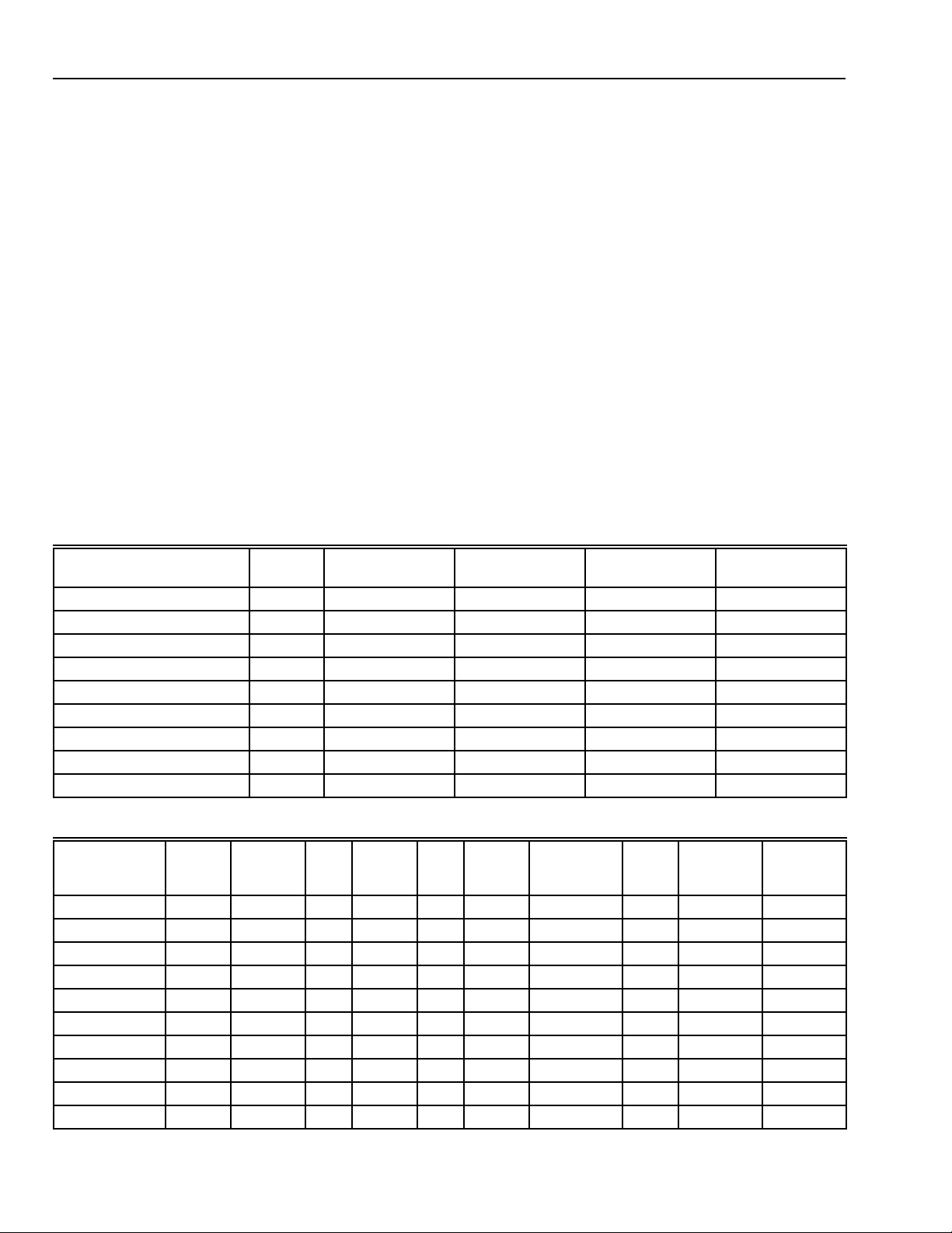
Table 7. Current use of Honeywell 7000 System devices.
Device
Control Panel with 8
Points
Keypad 120 120
PEM 60 60
RFEM 60 60
RF Receiver 50 50
Horn 0 950
2-Wire Smoke Detectors 0 25
Miscellaneous/AUX
Devices
* Miscellaneous/AUX devices can be relays, IR, etc. from the
AUX terminal, additional HBus devices (HSP, PEM, etc.), or
four-wire smoke detectors. Use the manufacturer current
ratings for this calculation.
M10906
Normal
Current (mA)
90 90
**
Alarm Current
(mA)
17
69-1192—1
Page 18
HONEYWELL 7000 SOLID STATE ALARM SYSTEM
IMPORTANT
The following limits must not be exceeded:
1. Maximum normal total current: 1.05A.
2. Maximum alarm current on TB1-18 (HORN):
950 mA.
3. Maximum alarm current on TB1-17 (AUX):
100 mA.
4. Maximum number of batteries: 4 (28 AH total
capacity).
5. Total current drawn from TB1-20 (+13.8 Vdc):
1.0A.
Minimum System
The minimum UL system is:
1. One control panel.
2. One keypad.
3. Up to 10 two-wire smoke detectors (or equivalent four-
wire smoke detectors).
4. One siren (950 mA model).
Table 8 summarizes the power calculations for this system.
Using the battery calculation formula:
(0.210A X 24 hours) + (1.185A X 1/15 hour) + 10% =
5.64 AH.
Table 8. Power calculations.
Normal Current
Device Quantity
Control Panel with 8 Points 1 90 90 90 90
Keypad 1 120 120 120 120
PEM 0 60 0 60 0
RFEM 0 60 0 60 0
5881 RF Receiver 0 50 0 50 0
Horn 1 0 0 950 950
Smoke Detectors 10 0 0 25 25
Miscellaneous/AUX Devices 0 0000
TOTALS 210 1185
Each
This configuration requires one 7AH battery.
Maximum System
The maximum system is any configuration that requires 28AH
of standby battery power.
Sample Configurations
Table 9 lists sample configurations. Any of these
configurations can be downsized (less modules or
components) and still meet the battery standby times for that
configuration. Installation per these guidelines will meet the
California State Fire Marshal (CFSM) 24-hour battery backup
requirement.
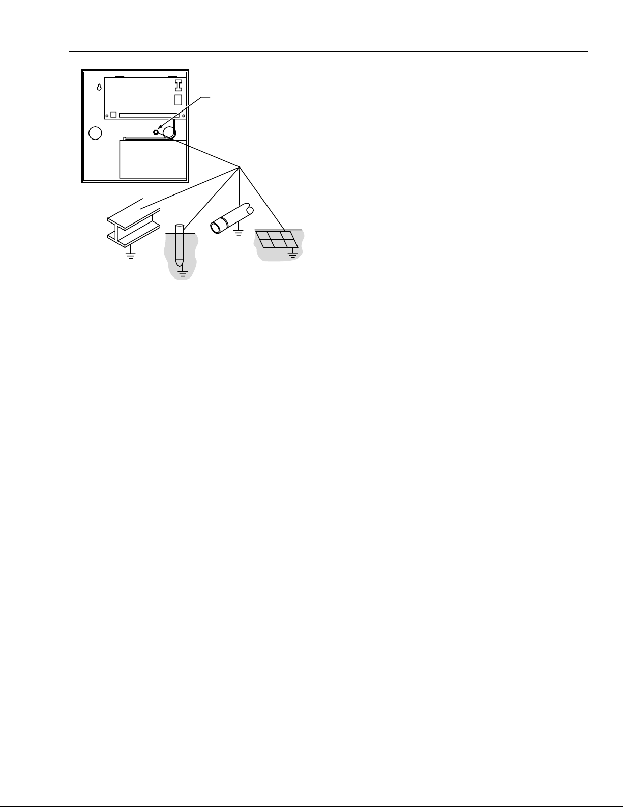
Earth Wire Grounding
An earth ground can be a cold water pipe, a ground rod, the
metal framework of a building, or the reinforcing rod (concrete
rebar) of a building as shown in Fig 20. The third wire ground
in building electrical wiring should not be used as earth
ground as it is difficult to establish reliability as an earth
ground.
Normal Current
Total
Alarm Current
Each
Alarm Current
Total
Table 9. Sample system configurations.
Configuration
No.
12417No1 11019263 1455
22418No0 21027301 1398
32418Yes 0 1 10 7 301 1405
424214 No 1 4 10 13 527 1865
524214 Yes 0 3 10 53 527 1870
624214 Yes 2 2 10 23 527 1870
*7 4 1 7 Yes 4 5 None 10 900 2000
*8 4 1 7 Yes 0 7 None 10 840 2000
*9 4 1 7 No 0 8 None 0 810 2000
*10 4 1 7 No 4 6 None 0 870 2000
*These configurations are for non-fire applications.
69-1192—1
Standby
Battery
Hours
Number of
Batteries
Total
AH
RF
RFEM +
RCVR PEM Keypad
18
2-Wire Smoke
Detectors
(Maximum)
Aux.
Power
(mA)
Maximum
Normal
Current (mA)
Maximum
Alarm
Current (mA)
Page 19
HONEYWELL 7000 SOLID STATE ALARM SYSTEM
PROGRAMMING
J1
BATTERY
S1
TB1
GROUND STUD
M10905
Fig. 20. Earth ground connection.
1. Make the connection to earth ground with a single No.
18 AWG wire connected to the control panel box
ground stud. Secure the wire to earth ground with a
suitable clamp to make sure that it is a solid mechanical
and electrical ground.
2. Avoid ground loops by connecting the shield of shielded
cables to the control panel box ground stud.
3. Secure the corners of the control panel circuit board to
the metal box and connect a single earth ground wire to
the metal box ground stud located on the center righthand side. Do not loop or daisy-chain any wires on the
circuit board terminal blocks to this ground stud.
The following steps will enable Programming. Refer to
Programming Instructions, form 24510169, for details.
Setup
NOTE: The following procedure steps apply to local
programming with a PC. If remote programming
(Downloading a program from the CSC) is
applicable skip steps 2 and 3: complete steps 4
through 7 to enable remote programming. The
system will be ready for the CSC to call, and the
system will connect, and the CSC program can be
downloaded. When complete select option 5 and
toggle the programming option to OFF.
1. Disconnect the Telco connection at the Telco jack, J1,
on the Control Panel circuit board.
2. Connect the PC (standard telephone) interface cable
from the PC Modem to the Telco Jack, J1, on the
Control Panel.
3. Enter a valid passcode and verify the system disarmed.
Factory default passcode is 1379. Have user select a
new master passcode after installation is complete.
4. Press the OPTIONS key and use the arrow keys to
scroll down to Option 5 “ALLOW PROGRAM”.
5. Press “5” to allow programming. Enable Programming
will last 15 minutes then the system automatically
returns to disable local programming.
6. Repeat the above procedure and press OPTIONS 6 to
enable the SERVICE Passcode to view EVENT LOG
records.
7. Repeat the above steps 1 through 7 and press
OPTIONS 8 if RF testing or verification will be required.
Powering Up and Disarming the System
1. Power up the system. Make sure all keypad LED are off
and the keypad displays either FACTORY TEST or
MASTER ARM.
2. If the keypad displays FACTORY TEST, program the
data base and download per instructions in the
Programming section.
NOTE: After downloading is complete, enter a valid
passcode into the Honeywell 7000 System to
activate the new data base.
3. Disarm the system by entering the programmed disarm
code (1 3 7 9) on any keypad. The keypad will indicate
SYSTEM DISARMED and READY.
The keypad will display AC POWER OFF if the ac is not
applied to the control panel.
The PEM has a status LED that is on steady when power is
first applied. After about 40 seconds, if the control panel
communicates successfully with the PEM, the LED will blink
at a one second on/off rate, after which the LED will blink five
times rapidly every time it communicates successfully with a
poll from the control panel.
This completes the physical installation of the system and
application of power. Proceed to the next section on
programming instructions.
Powerup
1. Turn on the PC.
2. Load and execute the System 7000 Programming
program.
3. In the program set all customer options and system
values per the instructions in the next section.
4. Download the data into the customers premise unit.
The panel will display: PROGRAMMING DONE
ENTER PASSCODE
5. Enter Passcode and system will reset with the new data
base active. The system will come up MASTER ARM.
Enter passcode a second time to disarm.
6. Repeat Option 7 to disable RF TEST MODE if
applicable.
NOTE: Remote program changes after downloading will
only take effect after the passcode resets the
system.
Disconnect the PC Interface cable and reconnect the telco
line to the RJ31 phone service when finished with
programming (see next section).
19
69-1192—1
Page 20

HONEYWELL 7000 SOLID STATE ALARM SYSTEM
Customer Data Entry:
The following control panel options are listed as a checklist to
make sure customer database information is not left out.
Refer to Programming Instructions, form 24510169, for stepby-step instructions with illustrations.
IMPORTANT
Do not program the Honeywell 7000 System to call a
fire or police station number unless authorized by
that fire or police station.
1. Open the customers program or a new one if the
program doesn’t exist (default program).
2. Establish or verify a customer three-digit ID (account)
number.
3. Fill in the Customer information.
4. Proceed to programmer options and fill in the name.
5. Fill in CSC dial out prefix if applicable.
6. Verify or add call-back number 1 to call the Central
Station.
7. Verify or add call-back number 2 to call the Central
Station.
8. Set city in the data base.
9. Select Programmer type - Local or by modem remote.
10. Enter the Comm. port of modem on PC.
11. Verify or select Dial Method Tone or Pulse.
12. Enter Modem Type.
13. Enter R-Dial Type yes or no.
14. Enter Modem speed - 300 or 1200.
IMPORTANT
The next step will send the program to the
customers Control Panel. Proceed to step 16 unless
you are ready to download information to the
System 7000.
15. At Transfer Main Menu Programming Information
submenu enter the Customer’s Phone Number. This is
not required for local programming.
16. Enter Customer’s Unit Account number - 001-999
17. Enter Passcode length 4,5, or 6.
18. Enter Duress Digit - 0-9.
19. Select passcode required for MODES yes or no.
20. Enter number of RF receivers - 0-2.
21. Select allow remote programming. Yes or No.
22. Select special Needs - Yes or No.
23. Add the CSC Receiver telephone Number 1
24. Specify delay seconds of report to CSC. - 00 to 99.
NOTE: UL Requires this to be set to 0.
25. Set dialing method pulse or tone.
26. Force 6500 Transmission to ZONEX - yes or no. See
programming guide for details.
27. Select if RF Troubles will be Reported. Yes or no.
28. Fill in the Callback phone number 1. Number of CSC
modem phone line.
29. Fill in the Callback phone number 2. Number of CSC
modem phone line. (Optional)
30. Enter the Pick up phone after how many rings. 1 to 15.
IMPORTANT
Watch out for other devices on the line such as
answering machines, FAX machines and local
telephone company options.
31. Enter the FIRE, POLICE, and SPECIAL Keypad point
numbers.
32. Enter Fire Audible Shutoff. UL requires this to be set to
4 minutes or greater.
33. Set Police, Special, and Tamper Audibles. Silent or not
silent.
34. Set the Entry/ Delay times. 0 to 255 seconds.
35. Pick customer city.
36. If necessary, pick time zone. Previous step should
exclude need for this entry.
37. Set daylight savings parameters. See Programming
guide.
38. Set EVENT TRIGGERS OUTPUT for each customer
output. See Programming Guide.
39. Set OUTPUT OPTIONS. Continuous or Momentary for
1 to 15 seconds. Bell/Horn output 1 is fixed continuous.
40. Set up the 8 AREA names.
41. Enter the points and how connected on each area/
zone.
42. Define Point Type (Hardwire or RF), Hardwire Use, and
Loop Type.
43. Enter each Serial Number for each RF Point Type
Transmitter. See marking on transmitter.
44. Enter Loop Number for RF Point Types.
45. Select RF Transmitter Type - Supervised, Non-sup or
Button.
46. Attach points to areas and select Point Names for the
points.
IMPORTANT
Use only Ademco 5800 Series Transmitters on the
Honeywell 7000 Control Panel.
47. Define Point Type (17 selections) see Programming
Guide.
48. Define OUTPUT and MODES for each point. See
Programming Guide for details on Modes on points that
are Strategy Point Types.
49. Repeat steps above as necessary to enter all points
into all zones in the system.
50. In the MODES Menu select the first mode and define it.
MODES can be Special or Normal. The following two
steps are for Special Points. Skip to step 53 for Normal
MODES.
51. Set Mode NAME, TYPE, PASSCODE LEVEL,
SPECIAL NEEDS, and OUTPUT ACTIVATION.
52. If Mode is to have a Smart Point select which Smart
Point, then select CHANGE POINT and set the point to
ARM, DISARM, ON WATCH, or NO CHANGE.
53. Set Normal Mode NAME, TYPE, PASSCODE LEVEL,
SPECIAL NEEDS, OUTPUT ACTIVATION, DELAY,
OCCUPANCY STATE, CHANGE POINT TO STATUS,
and CHANGE POINT STATUS TO.
54. In the Passcodes Menus set up all 10 passscodes plus
the inactive or temporary, and attach an authority level.
(See Programming Guide for details)
55. Download the Customer Data into the 7000 System by
selecting SEND PROGRAM in the TRANSFER MAIN
Menu.
56. Wait for the message “PROGRAMMING
SUCCESSFUL”.
57. Print out a hard copy of the Customer Data to verify
that all the sales options have been entered. Keep this
copy for history records. Save the customer data on the
PC’s hard disk.
69-1192—1
20
Page 21
HONEYWELL 7000 SOLID STATE ALARM SYSTEM
NOTE:
1. Data must be read by an external text reader after it
is saved on the hard disk drive.
2. After programming system will require a valid
passcode to be entered to activate the new data
base.
58. If programming is complete disconnect the PC
Programmer and reconnect the Telco connections to
the RJ-31X block. See Figure 27.
OPERATION
This section provides general operation instructions for the
Honeywell 7000 Solid State Alarm System. All operating
procedures can be done from the keypad.
Keypad
The system can include more than one keypad. If so, each
keypad operates in conjunction with the others and the
system can be controlled from any one of them. Messages
and any user requested operation will appear the same way
on every two-line display at the same time. The non-alarm
sounds can be silenced on selective displays to avoid waking
people up when returning home late.
c. Arrow Keys
Used to scroll through menus having more than 2 selections.
The Display shows the current mode, and the down arrow,
when pressed, will show all points that are not ready. The up
arrow key shows the points that are bypassed and the special
protection points that are disarmed.
d. Audible Feedback
Each time you press any key, an audible tone will sound to
confirm successful entry of a digit or function.
e. LED’s
Two LED’s between arrow keys. The LED next to the UP
arrow, when lit, indicates that some Special Protection is
turned off or Security Points have been bypassed. The LED
next to the DOWN arrow, when lit, indicates a Point of
Protection such as a window or door is open.
FIRE
Press and hold this key for two seconds anytime regardless
of mode or security status, and an instant fire alarm is
transmitted to the CSC, which will dispatch the fire
department and notify the first available person on the call
list.
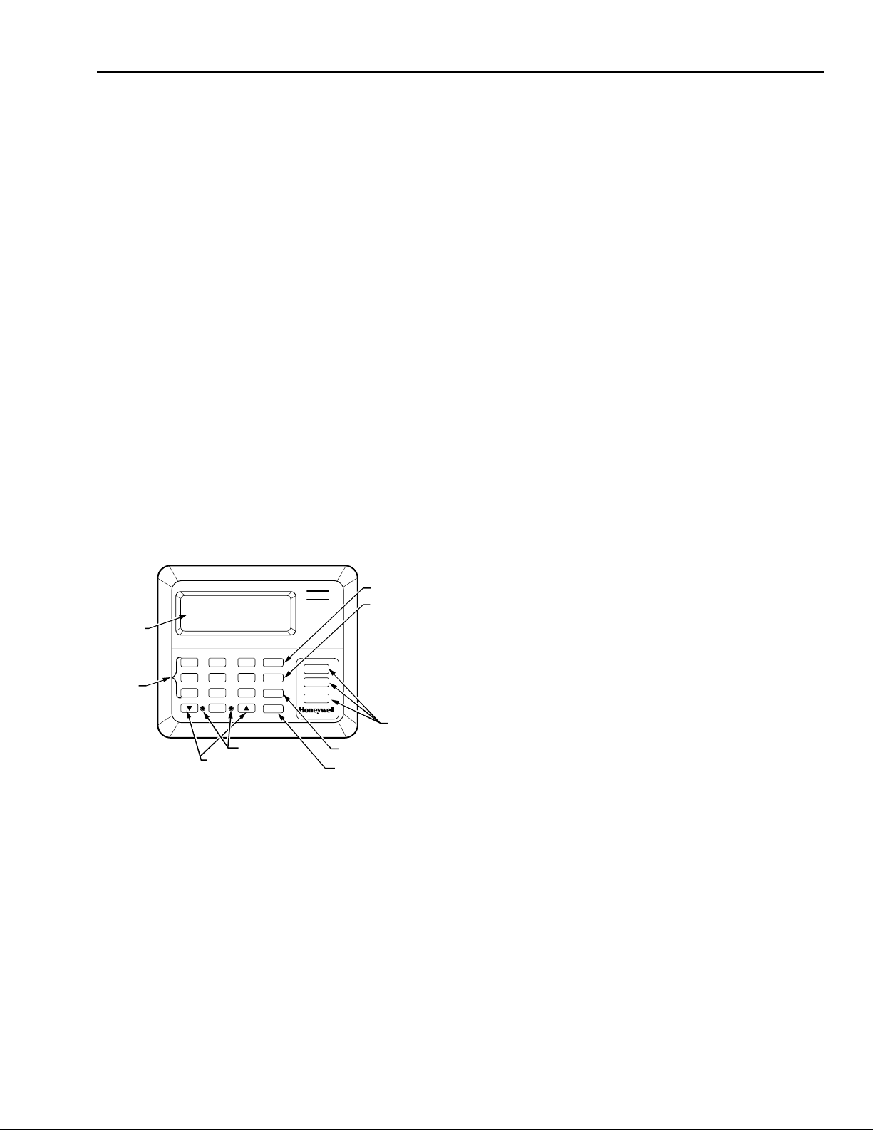
Fig. 21 shows the keypad and the following provides a brief
description of the display and key functions.
MODES KEY
OPTIONS
DISPLAY
NUMBER
KEYS
1
2
45
7
89
0
ARROW KEYS
3
6
LED
MODES
OPTIONS
OK
CANCEL
FIRE
POLICE
SPECIAL
KEY
OK KEY
CANCEL KEY
SPECIAL
KEYS
M10897
Fig. 21. Keypad layout.
a. Two-Line Display
Words appear here to offer menu choices and tell you what’s
happening with the system, including system status and
location of alarms, open points or system troubles. More than
2 lines can be displayed by scrolling information 2 lines at a
time.
b. Numbered Keys
Used to enter passcodes and make menu selections.
POLICE
Press and hold this key for two seconds anytime regardless
of mode or security system status and an immediate alarm is
transmitted to the CSC, which will dispatch the police and
notify the first available person on the call list. Police can be
programmed to be silent, however the Keypad will still display
POLICE ALARM.
SPECIAL
The emergency function of the system was determined at the
time of installation. When monitoring of this button is
included, you need to press and hold this key for two seconds
and an immediate alarm is transmitted to the CSC, which will
dispatch the pre-determined help and notify the first available
person on the call list. The Special button can be
programmed to be silent, however the Keypad will still display
SPECIAL ALARM.
MODES
Press to display a menu of the modes pre-programmed for
the system. Arrow keys allow scrolling up or down to see
additional selections. Use the number keys to make the
selection.
OPTIONS
Press to display the options menu. Use arrow and number
keys to locate and make selections.
OK
Press this key to confirm selections.
21
69-1192—1
Page 22
HONEYWELL 7000 SOLID STATE ALARM SYSTEM
CANCEL
Press this key to cancel a menu selection or operation. If you
are at a menu selection the cancel key allows you to backup
to the previous screen.
CONTEXT SENSITIVE HELP
During any keypad interaction if you pause more than 7
seconds without hitting a key the system assumes that help is
appropriate at that time. The Keypad will then provide help
for the specific function you are performing. After help is
provided the display returns to the current function. Seven
seconds later the cycle is repeated and the specific help
message is presented two more times. The messages are
always pertinent to the area of the system you are currently
effecting.
Modes
1. The System 7000 system allows you to manage
numerous security appliances with one control. In order
to simplify the choices and make the system quick and
easy to operate, a group of pre-programmed
commands have been organized into modes.
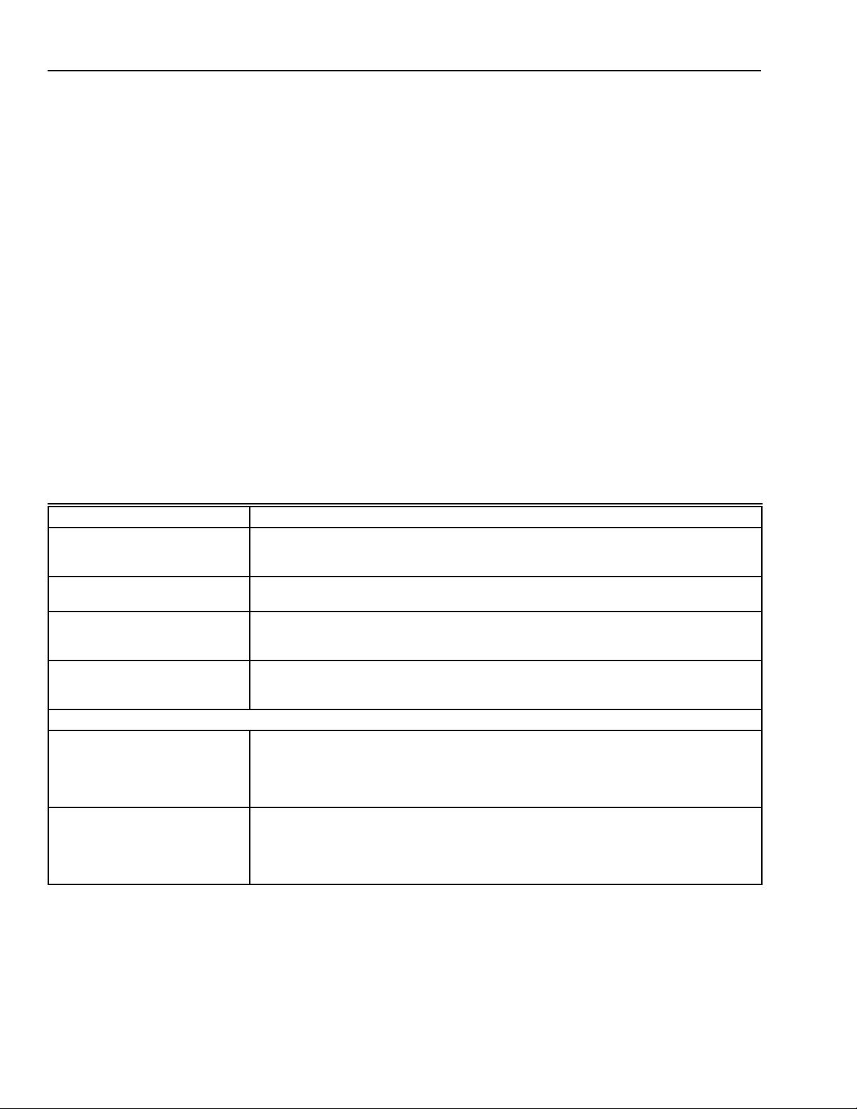
Table 10. Examples of Security Modes.
2. A Security mode activates a particular arrangement of
sensors and instructions that tell the security system
what to do which you and the Honeywell representative
selected when the system was installed. A Special
Protection mode changes the protection for special
areas or objects such as the home office, safe,
workshop, liquor cabinet, gun rack etc. Up to eight
security and eight special protection modes are
available. Each can be described by 12 character that
are convenient for the use.
Examples of possible Security modes are listed in Table 10.
Alarm and Trouble Indications on the Keypad
1. Entry/Exit Delay:
Pulsed low tone one second ON, 0.1 second OFF for
the duration of the programmed Entry 1 or 2, or the Exit
delay timer. “EXIT NOW” is displayed on line 1 of the
LCD. Audible Increases in speed for the last 10
seconds. Exit audible is silent for home occupancy
modes.
2. Burglary Alarm:
Continuous loud tone, the point alarm description is
displayed on line 1, the BURGLARY warning message
on line 2. The outside siren is delayed 15 seconds.
Mode Description
SLEEP • All security armed except for bedroom area motion detector.
• Living room motion detector is ON WATCH.
• Special Protection for the home office is turned on.
AWAY • All perimeter and security is armed.
• Special Protection for the home office is turned on.
HOME ALONE • Interior motion detectors are off.
• Perimeter security is ON WATCH.
• Special Protection for the home office is turned on.
ON WATCH • All perimeter is ON WATCH and will chime when violated.
• Interior protection is off.
• Special Protection for the home office remains as previously set.
Examples of Special Protection modes include:
OPEN OFFICE • Special Protection for the home office is turned off.
• OPEN OFFICE is momentarily displayed on the keypad.
• The LED next to the UP arrow lights.
• The name of the previously selected Security mode is displayed.
• All other security from previously selected Security modes remains in effect.
CLOSE OFFICE • Special Protection for the home office is turned on.
• CLOSE OFFICE is momentarily displayed on the keypad.
• The LED next to the UP arrow goes out.
• The name of the previously selected Security mode is displayed.
• All other security from previously selected Security modes remains in effect.
69-1192—1
22
Page 23

HONEYWELL 7000 SOLID STATE ALARM SYSTEM
3. Fire Alarm:
Pulsed loud evacuation tone sequence. Three bursts
ON then, OFF for three burst periods, and then repeats.
Outside siren is delayed 15 seconds. The Fire point
description that triggered the alarm is displayed on line
and the FIRE warning message is displayed on line 2.
4. Fire Trouble:
Pulsed low tone, 0.1 second ON, 0.1 second OFF. Fire
trouble point description is displayed on line 2 with the
FIRE TROUBLE warning message on line 1 There is
no outside siren annunciation.
5. Police Alarm:
Pulsed loud tone, one second ON, 0.1 second OFF,
and the outside siren is instant (if programmed as an
audible). The police point description is displayed on
line 1 with the POLICE warning message on line 2.
6. Police Duress:
The duress feature is inactive if there is any keypad
activity 10 seconds prior to pressing the duress digit.
The Duress alarm is available on all Honeywell 7000
Control Panels. The duress digit is a programmable
feature that can be selected at the time of installation.
Pressing the duress digit followed by a valid disarm
code activates the silent duress alarm; however the
system disarms normally. There are no audible or
visible alarm indications at the keypad.
7. Special Alarm:
Pulsed loud tone, 0.5 second ON, 0.5 second OFF, the
outside siren is instant (if programmed as an audible).
The special point description is displayed on line 1 with
the SPECIAL warning message on line 2.
8. Transmitter In Trouble:
The Transmitter In Trouble condition is due to the loss
of the supervisory test message sent to the RF
Receiver. The Control Panel dials the CSC if
programmed to do so.
The system will remember all transmitters in a trouble
condition and display them. For example, the KEYPAD
display will show:
1. TROUBLE TX.
2. GROUP NAME.
3. POINT DESCRIPTION.
The above display will scroll through several times as
necessary if multiple transmitters are in trouble.
The above message will appear after a transmitter goes into
trouble AND a one second tone (similar to the ON WATCH
tone) will annunciate once every minute. To quite the one
second per minute audible, enter the disarm code. The
display is reset by sending a valid signal from the troubled
transmitter.
9. On Watch:
The ON WATCH Feature sounds a one second low
tone and hardwire/transmitter point description is
displayed on line 2 for 20 seconds.
10. System Low Battery:
System Low Battery condition occurs when the control
panel senses the battery voltage drifting through 11.5
volts and resets when the control panel senses the
battery rising through 12.0 volts.
11.Tamper Alarm:
Continuous loud tone displayed the same as any other
burglary point. This hardwire point is programmed as a
24 hour burglary zone. External Siren is delayed 15
seconds.
12. Transmitter Low Battery:
A tone will be heard between 8 AM and 8 PM. This
could be up to 12 hours after displaying the message.
The tone delay is to avoid annunciation during sleeping
hours. Each time the transmitter is activated while in a
low battery state (either by the supervisory transmission
or transmitter activation), the control panel will display
this condition and start the 12 hour tone delay. The low
battery condition will occur at a voltage of
approximately 8.0 volts (7.5 +/- 0.4 volts while
transmitting). The KEYPAD display can be cleared from
the KEYPAD by replacing the battery and then entering
the disarm code.
13. Horn Failure:
A Horn Failure condition occurs when the system
senses that the wiring to the external horn is open or
shorted to ground.
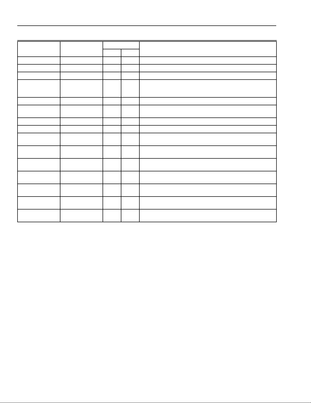
Table 11 provides a listing of keypad LCD and LED
responses to system operation.
Emergency System Shutoff:
This procedure will completely disable the entire security
system including the 24 hour protected points, the display
Keypads, and outputs.
Use this procedure only as a last resort if:
1. All efforts to turn off the audible alarms fail, or
2. You cannot disarm the security portion of the system by
any other means, or
3. You want to turn off the System 7000 System for any
other reason.
To shut off the system, unlock and open the Control Panel.
Locate the POWER switch near the right end of the circuit
board. Slide the switch to the OFF position.
IMPORTANT
Call the Honeywell Customer Service Center
immediately, provide the passcard number and
describe the problem.
Power Failure
To keep the System 7000 system functioning during a power
failure it is equipped with a rechargeable back-up battery.
This battery will operate for a minimum of four hours (24
hours for fire). While the security system is on battery power,
the security system will function normally. You will see an “AC
POWER OFF” message on the Keypad panels.
If a power failure lasts longer than the charge in the
battery(s), the entire security system including the 24 hour
protected points, the KEYPAD Panels and programmed
outputs will be disabled. Alarms will not sound in the event of
a burglary, fire or intrusion, and the CSC will not receive
signals from the system.
The modes, passcodes and information programmed into the
System 7000 system will not be affected, and once power is
restored the system will begin operation immediately. Open
and close all points protected by RF transmitters once and
the system resets itself and is fully operational. If the
installation does not have any RF transmitters, it will reset
itself automatically.
23
69-1192—1
Page 24
HONEYWELL 7000 SOLID STATE ALARM SYSTEM
Table 11. Keypad LCD and LED response to system operation.
Keypad LED
Keypad Display Audible Left Right Comments/Interpretations
System Off None Off off System in Standby Mode; 24-Hour Points and Fire active.
Mode None Off Off System in selected Mode.
Alarm ON Off On System in Alarm Mode; see second line of display for alarm type.
Fire Alarm On (External
Police Alarm On or Silent Off Off System normal if silent; otherwise in Alarm.
Special Alarm
Message
System Trouble ON off Off Message identifies type of trouble; see message.
Ac Power Failure None Off Off Problem displayed; resets when power restored.
Low Battery Low tone once a
Fire Trouble Low tone
Comm CSC
Failure
RFEM Trouble Low tone once a
ON Watch Low tone when
Pool Point On for 30 seconds
Horn Failure Low tone
delayed for 15
seconds)
On or Silent. off Off System displays Alarm; see second line of display for alarm type.
minute.
repeating.
Low tone once a
minute.
minute.
tripped.
if away.
repeating.
Off Off System in Alarm Mode; see second line of display for alarm type.
Off Off Problem displayed; resets when battery replaced.
Off Off Problem displayed until circuit restored.
Off Off Problem displayed until message received at CSC.
Off Off Message displayed until RF service restored.
Off On Point ID Message on for 10 seconds.
Off On Can be ON-WATCH or Armed.
Off Off Problem displayed; reset when problem resolved and password
entered.
Emergency System Shutoff
This procedure will completely disable your entire security
system including the 24 hour protected points, the display
Keypads, and outputs.
Use this procedure only as a last resort if:
1. All efforts to turn off the audible alarms fail, or
2. You cannot disarm the security portion of the system by
any other means, or
3. You want to turn off your System 7000 System for any
other reason.
To shut off the system, unlock and open the Control Panel.
Locate the POWER switch near the right end of the circuit
board. Slide the switch to the OFF position.
IMPORTANT
Call the Honeywell Customer Service
Center immediately, provide your passcard
number and describe the problem.
CHECKOUT
System Installation Test
Local Test Sequence
NOTE: After performing this test and verifying that the
system is working properly, repeat the test with the
customer/home-owner to show him how that the
system operates as intended.
1. Power up the system and verify the KEYPAD(s) are
displaying MASTER ARM .and both LED’s are OFF.
2. Verify there were no alarm audibles. (Hardwire points in
the alarm state will go into alarm within 45 seconds
after power-up, Fire after 20 seconds).
3. With the arrow keys verify that all points are normal. If
any are open , correct and proceed.
4. Enter a valid passcode and verify that the System goes
into the default Mode (disarmed).
5. Push the MODES key and select a mode with points in
ON WATCH. (If some points in this mode are
programmed for ALARM, they will go into ALARM.)
69-1192—1
24
Page 25

CAUTION
Personal Injury Hazard.
Can cause hearing damage.
Wear hearing protection devices when testing bells,
horns or sirens. If hearing protection is not available,
muffle the audible devices until after the test.
6. Exercise each Perimeter point and verify that the
correct description is displayed along with a one
second tone. When opening the contacts, the right LED
lights.
7. Exercise each Entry/Exit point and verify that the
correct description is displayed.
8. Exercise each Interior point and verify that the correct
description is displayed for the interior zone selected.
When opening the contacts, the right LED lights.
9. Exercise each Fire sensor and verify that the correct
description is displayed. The only hardwire Fire point is
P8. The KEYPAD will alarm locally, immediately and the
external siren or bell turns on.
10. Exercise any SPECIAL or POLICE points in the system
and verify the correct descriptions. The hardwire Police
and Special loops on TB1 display the same description
as their respective KEYPAD keys. The READY display
on the KEYPAD is replaced with the special or police
alarm message. The KEYPAD audible and outside
siren are both instant if programmed as audible.
NOTE: After a power outage long enough to fully
discharge the battery, or if the Control Panel is
turned OFF, the user must test all points of
protection to update the status of each RF
point in the Control Panel memory.
11. Enter a mode with points armed and exercise a point.
12. Verify the External Bell and output options function as
programmed.
HONEYWELL 7000 SOLID STATE ALARM SYSTEM
Customer Service Center (CSC) Test
1. Call the CSC to coordinate testing of the system.
2. Reconnect the telephone cord from the Control Panel
to the RJ-31X jack.
3. Press the MODES key and arm the system.
4. Cause a point to alarm, and enter the disarm code.
NOTE: After the first disarm, the Control Panel sends the
restore message to the CSC.
Testing The Duress Code
1. Put the system into the AWAY mode as described in the
“User Guide”.
2. Wait 10 seconds in between any KEYPAD activity
before trying the duress code.
3. Enter the duress digit followed by the master disarm
code. Verify the control panel seizes the phone line and
dials out the police alarm and that the Honeywell 7000
does not send in a restore message to the CSC.
4. Call the CSC and confirm correct reception of all alarms
and restore messages that should have been received.
Testing Local Telephone Connections
1. While the dialer communication is in progress, all of the
telephones in the house are seized by the Control
Panel. To verify that the RJ-31X jack is wired correctly,
go to each telephone, pick up the receiver and listen.
No dial tone or other dialing sound should be heard.
2. Unplug the telephone cord from the RJ-31X module
and ensure that the house phones work properly.
Final Configuration Form
Help the customer fill out the configuration form in the User
Manual.
To Verify Or Test RF Points And Descriptions
1. Press the MODES key, scroll and select number 8, the
RF TEST Option. Press 0, then OK, to put the System
into RF Test (receiver sensitivity reduced 12 dB).
NOTE: If the next step does not occur in three
2. Trip the RF Transmitter to be tested twice within 8
seconds. The Transmitter Point ID description will
appear, and the KEYPAD will annunciate a one second
tone.
IMPORTANT
1
minutes, the system will automatically return to
the Default mode.
Use only Ademco 5800 transmitters on the
Honeywell 7000 System control panel.
TROUBLESHOOTING
The security portion of the Honeywell 7000 System is
constantly checking itself and will report problems the Keypad
display.
The system test should be performed locally, and then a CSC
communication test should be performed.
Your system may or may not include radio frequency
transmitters. If it does not, the RF transmitter information
below does not apply.
NOTE: Disconnect the phone cord from the RJ-31X
phone jack until local testing is completed.
Table 12 lists trouble messages, indications and possible
solutions. Follow the What You Should Do instructions in
order.
25
69-1192—1
Page 26

HONEYWELL 7000 SOLID STATE ALARM SYSTEM
Table 12. Troubleshooting guide.
What You See What is Wrong What You Should Do
HOME NOT READY
FORCE ARM? These
Points not ready.
HOME FIRE TROUBLE
SMOKE DETECTOR
(NOTE: A warning tone will
also sound.)
HOME TROUBLE TX
GUEST WINDOW
HOME AC POWER FAIL 1. The low voltage ac
HOME SYS LOW
BATTERY
No display is showing. There is no ac or backup battery
1. A protected point is open
and/or:
2. A transmitter cover is open.
Wire to fire sensors is damaged. 1. Check for signs of fire. If none:
1. Defective battery.
2. Loose battery lead(s).
3. Transmitter malfunction.
4. Receiver malfunction.
transformer is loose or
unplugged.
2. Power failure.
The Control Panel system backup
battery is defective or weakened
after extended ac failure.*
power to the system.
1. Press the right arrow button to look at open points.
2. Open and close the named door or window and leave it
closed.
3. If your system includes rf transmitters, check the
transmitter at the named location and make sure the
cover is tightly closed.
2. Enter your passcode to silence the warning tone.
3. Call Honeywell for service.
1. Clean the battery connections. if this fails, replace the
battery.
2. Tighten the battery and the battery clip. Reconnect the
battery and test the system.
3. If replacing the transmitter battery does not solve the
problem, call Honeywell for service.
4. If the keypad display indicates that all points are in
trouble, the receiver may be defective. Call Honeywell
for service.
1. Check the low voltage transformer usually located near
the control panel.
2. Restore house power. If there has not been a power
failure, call Honeywell for service.
Call Honeywell for service.
1. If only some lights are out in your home, check house
circuit breakers or fuses and restore as necessary.
2. Make sure the low voltage transformer near the Control
Panel is securely plugged into an ac outlet.
3. Call Honeywell for service.
*NOTE: The CSC receives a signal from your system when
low battery problems occur, and notifies the first
available person on your call list.
Telephone Problems
In the event of telephone problems, disconnect the control
panel by removing the plug from the RJ31X (CA38A in
Canada) wall jack. This should leave the rest of the House
phones in service if the problem is with the security
equipment. Do not disconnect the phone connection inside
the control panel or the local phones will be out of service. If
the telephone service is still out after disconnecting the
security system the problem is with the phone system and
they should be contacted for service. If the phones service
returns when the security system is disconnected then
Honeywell should be contacted for service.
REGULATORY AGENCY STATEMENTS
UL Installation Requirements
The following installation requirements apply to UL - 1023 Grade A Household Burglar Alarm, for UL 985 Household
Fire, and UL 1635 - Digital Burglar Alarm Communicator
System Units, and UL 1637 Home Health Care Signaling:
1. All wiring and interconnections must be owned and
managed by the same person(s).
2. All wiring and interconnections must be located at one
address.
3. At least one audible alarm device must be placed
where it can be heard at the installation location.
4. Per NFPA72, Battery backup capabilities must be
provided for 24 hours of normal service followed by at
least 4 minutes of File Alarm signaling.
5. The maximum Ampere Hour Battery load for
System 7000 is 28 AG without a Listed Auxiliary Power
Supply.
6. The minimum Ampere Hour Battery is 7 AH and current
load is restricted to 210 milliamps normal standby and
1.185 amperes of alarm for 4 minutes for 24 hours of
battery backup.
7. Use ALARM-SAF AP/PS5BF 12-UL when auxiliary
power is required.
69-1192—1
26
Page 27

HONEYWELL 7000 SOLID STATE ALARM SYSTEM
California State Fire Marshal (CSFM)
Requirements
24 hour battery back-up:
1. Per NFPA72, Battery backup capabilities must be
provided for 24 hours of normal service followed by at
least 4 minutes of File Alarm signaling
2. The maximum Ampere Hour Battery load for System
7000 is 28 AH without a Listed Auxiliary Power Supply.
3. The minimum Ampere Hour Battery is 7 AH and current
load is restricted to 210 milliamps normal standby and
1.185 amperes of alarm for 4 minutes for 24 hours of
battery backup.
4. Use ALARM-SAF AP/PS5BF12-UL when auxiliary
power is required on CSFM installations.
5. Use ADEMCO 747UL Sirens for audible
requirements.
Federal Communications Commission (FCC)
Statement
This equipment has been tested to FCC requirements and
has been found acceptable for use. The FCC requires the
following statement for your information:
This equipment generates and uses radio frequency energy
and if not installed and used properly, that is, in strict
accordance with the manufacturer’s instructions, may cause
interference to radio and television reception. It has been type
tested and found to comply with the limits for Class B
computing device in accordance with the specifications in
Part 15 of FCC Rules, which are designed to provide
reasonable protection against such interference in a
residential installation. However, there is no guarantee that
interference will not occur in a particular installation. If this
equipment does cause interference to radio or television
reception, which can be determined by turning the equipment
off and on, the user is encouraged to try to correct the
interference by one or more of the following measures:
1. If using an indoor antenna, have a quality outdoor
antenna installed.
2. Reorient the receiving antenna until interference is
reduced or eliminated.
3. Move the receiver away from the control/communicator.
4. Move the antenna leads away from ant wire runs to the
control/communicator.
5. Plug the control/communicator into a different power
outlet so that it and the receiver are on different branch
circuits.
6. If necessary, the user should consult the dealer or an
experienced radio/television technician for additional
suggestions.
7. If necessary, consult the booklet entitled “Interference
Handbook”, prepared by the FCC. It is available from
the U.S. Government Printing Office, Washington, DC
20402.
This equipment complies with Part 68 of the FCC rules. On
the front cover of this equipment is a label that contains,
among other information, the FCC registration number and
ringer equivalence number (REN) for this equipment. If
requested, this information must be provided to the telephone
company.
The REN is needed to determine the quantity of devices that
may be connected to the telephone line. Excessive REN on
the telephone line may result in the devices not ringing in
response to an incoming call. In most, but not all areas, the
sum of the REN should not exceed five (5). To be certain of
the number of REN that may be connected to your telephone
line, add up the REN on your line and call the local telephone
company and verify that you are below the maximum limit for
your area.
If this equipment causes harm to the telephone network, the
telephone company will notify you in advance that temporary
discontinuance of service may be required. If advance notice
is not practical, the telephone company will notify the
customer as soon as possible. Also, you will be advised of
your right to file a complaint with the FCC if you believe
necessary.
The telephone company may make changes in its facilities,
equipment, operations, or procedures that could affect the
operation of the equipment. If this happens, the telephone
company will provide advance notice in order for you to make
the necessary modifications in order to maintain uninterrupted
service.
If trouble is experienced with this equipment, please contact
the manufacturer for repair and warrantee information.
If the trouble is causing harm to the telephone network, the
telephone company may request you to remove the
equipment from the network until the problem is resolved.
This equipment uses a RJ31X to connect the System 7000 to
the telephone network.
There are no user serviceable components in this product,
and all necessary repairs must be made by the manufacturer.
Other repair methods may invalidate the FCC registration on
this product.
This equipment cannot be used on telephone companyprovided coin service. Connection to Party Line Service is
subject to state tariffs.
This equipment is hearing-aid compatible.
When programming or making test calls to an emergency
number, prior to initiating alarms, briefly explain to the
Monitoring dispatcher the reason for the call. Perform such
test activities in the off-peak hours; such as early morning or
late evening.
The user shall not make any changes or modifications to the
equipment unless authorized by the Installation Instructions
or User’s Manual. Unauthorized changes or modifications
could void the user’s authority to operate the equipment.
27
69-1192—1
Page 28

HONEYWELL 7000 SOLID STATE ALARM SYSTEM
Home and Building Control
Honeywell Inc.
Honeywell Plaza
P.O. Box 524
Minneapolis MN 55408-0524
Honeywell Latin American Region
480 Sawgrass Corporate Parkway
Suite 200
Sunrise FL 33325
69-1192—1 G.R. Rev. 9-98
69-1192—1
Home and Building Control
Honeywell Limited-Honeywell Limitée
155 Gordon Baker Road
North York, Ontario
M2H 3N7
Honeywell Europe S.A.
3 Avenue du Bourget
1140 Brussels
Belgium
Printed in U.S.A. on recycled
paper containing at least 10%
post-consumer paper fibers.
28
Honeywell Asia Pacific Inc.
Room 3213-3225
Sun Hung Kai Centre
No. 30 Harbour Road
Wanchai
Hong Kong
www.honeywell.com/yourhome
 Loading...