

Page 1
Under no circumstances should the outer wall of the
window frame be penetrated by the Forstner bit.
Figure 1
Using a 3/4" Forstner Drill Bit
with a stop collar, drill into the
vinyl window mainframe.
5800MICRA
Wireless Recessed
Transmitter
Installation Instructions
GENERAL INFORMATION
The 5800MICRA wireless recessed transmitter is a reed switch magnetic contact
transmitter that allows the transmitter to be concealed from view when installed
in a window. It is intended for use only with alarm systems that support 5800 series
devices. The transmitter is powered by a long-life lithium battery that is easily
replaceable when a low battery is indicated by the control panel.
Programming the ID Number
Each 5800MICRA has its own unique identification code (serial number)
permanently assigned during manufacturing.
The control panel is required to "enroll" the transmitter's ID during installation of
the alarm system. The zones input type should be enrolled as "RF" (i.e. Supervised
RF) Type (mandatory for all UL installations).
Refer to the control panel's installation instructions for further details.
PRELIMINARY CONSlDERATlONS
Read all of this and the next section before installing the unit.
1. Select a location for the transmitter on the frame of the window.
Do not use on metal frame doors or windows.
5800MICRA TRANSMITTER
The 5800MICRA transmitter will require a 3/4" diameter hole (using
a 3/4" Forstner bit) drilled into the edge of the window frame no more
than 11/32" deep. Its accompanying magnet will need a 3/4" diameter
hole drilled in the side of the window sash, no more than 11/32" deep.
BEFORE DRlLLlNG ANY HOLES, SEE ITEM 2 BELOW AND MOUNTlNG
SECTION ON PAGE 2.
FOR VINYL SLIDING WINDOWS the preferred direction of mounting is vertical.
FOR HUNG WINDOWS the 5800MICRA must be mounted horizontally in the
window sill with the accompanying magnet mounted in the lower window sash.
(see Step 1 - Measure & Drill in Figure 1)
2. Before drilling any holes, tape the transmitter and magnet in their
approximate locations (with battery installed and unit together as
described under BATTERY INSTALLATION / REPLACEMENT (see Page 2)
and conduct Go/No Go tests (see control's instructions) to verify
adequate signal strength. Reorient or relocate the transmitter if necessary.
Make sure that no more than a 1/2" gap will be present between the faces
of the transmitter and magnet cases when they are installed and set. Also make
sure the 'iON' graphic on the transmitter and magnet are aligned with each
other as per Step 3 - Sash Magnet Placement in Figure 1.
When installed, an alarm signal must be obtained before a clear space of 2"
is reached as the window is opened.
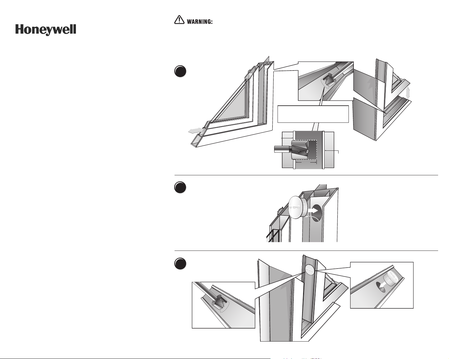
Measure & Drill
1
Horizontal
Sliding Sash
Measure 3" down from the inside top corner of the
mainframe and mark the center point for the hole the
5800MICRA transmitter will be inserted into.
Place a corresponding mark also on the sash insert that
will be used in this position.
Place and Set
2
Sash Magnet
3
Placement
Using a 3/4" Forstner Drill Bit, drill into the
window sash to a depth of 11/32" only.
Side mount
transmitter
on Vinyl
Sliders
WARNING: under no circumstances
should the outer wall of the window
frame be penetrated by the Forstner bit.
inner wall
of window
frame
3/4" Forstner
drill bit
0.5"
< extrusion hollow >
11/32"
core depth
Sill mount transmitter
on Hung Windows
outer
wall of
window
frame
Insert the 5800MICRA's antenna into the
extrusion hollow then press the transmitter
body into the cored opening. Insure that the
antenna moves freely in the window channel
during installation.
NOTE: It is essential to the systems operation
that the positioning of the iON icon on the
transmitter point in the same direction as its
corresponding sash magnet.
Sash Magnet
Press the 5800MICRA transmitter's corresponding
magnet into the cavity now drilled into the sash,
making sure to position the iON icons to point in the
same direction.
the systems proper operation.
NOTE: This point is essential to
Vertical Sliding
Sash
Page 1
Page 2
Page 2
5800MICRA
Wireless Recessed
Transmitter
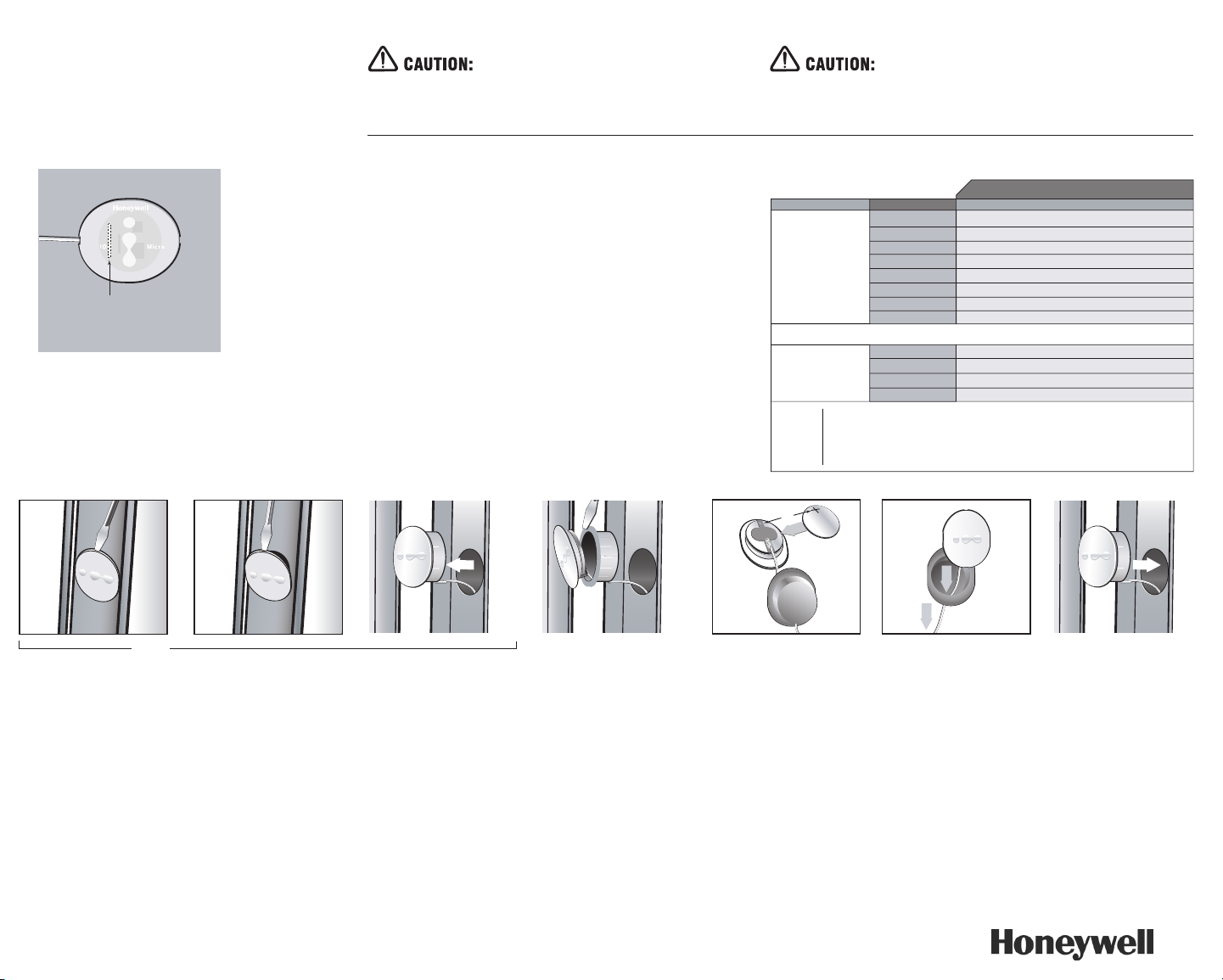
Reed Switch on
top side of PC board
(inside cap)
Reed Switch Positioning - insure that logos on
switch and magnet are aligned identically.
Figure 3
Before drilling any holes, make sure that successful
Go/No Go transmission reception tests have been conducted as called for in the
5800MICRA transmitter section.
MOUNTING
1. Mark the selected location for the transmitter on the frame of the window.
2. Mark the location for the magnet on the window sash, directly opposite the
3. Drill holes at the locations marked, for the transmitter (3/4" diameter, no
4. lnsert the transmitter and magnet cases into their respective holes so that
DO NOT hammer the transmitter or the magnet in place with hard blows.
Press them into their respective holes by hand.
The 5800MICRA uses a santaprene case that, once placed, is designed to selfseal in the mounting hole. However, if desired, a thin bead of silicon may be
applied for additional moisture protection.
(See Figure 1)
transmitter location. Before drilling any holes, make sure that the successful
Go/No Go reception tests have been conducted as called for in the 5800
MICRA transmitter section. (see Page 1)
more than 11/32" deep) and magnet (3/4" diameter, no more than 11/32"
deep using a 3/4 Forstner bit).
their caps are flush with the surface. Make sure the antenna goes into the
cavity as straight as possible.
BATTERY CAUTION: Risk of fire, explosion and burns.
Do not recharge, disassemble, heat above 212"F (100"C) or incinerate. Dispose
of used batteries promptly. Keep away from children.
Figure 2
SPECIFICATIONS 5800MICRA transmitters
Dimensions Dowel Package 0.750" diameter (3/4")
Power Source 3.0V Lithium Coin Cell Battery CR1620
Transmit Range Typically >500 ft. open air
Temperature Range 10º to 120º F (-12º to 49º C)
Operating Gap 0.5"
Compatibility Windows All Vinyl Window Types, Wood Casement, Awning,
IC number 4488A-5800M
FCC Identification QN35800M
FCC
Notice
Additional Info Dowel Lid 0.850" diameter x 0.060" thick
Wire Antenna 11" x 0.050" diameter (24 gauge)
Fits Cavity Depth 0.330" depth (11/32")
Double-Hung and Access
This device complies with FCC Rules Part 15. Operation is subject to the following two conditions:
1. This device may not cause harmful inter ference.
2. This device must accept any interference that may be received, including inter ference that may
cause undesired operation.
Changes or modifications not expressly approved by the Honeywell Corporation can void the user’s
authority to operate the equipment.
+
STEP 1 STEP 2 STEP 3 & 4 STEP 5 & 6 STEP 7
TO THE INSTALLER
Regular maintenance and inspection (at least
annually) by the installer and frequent testing by the
user are vital to continuous satisfactory operation of
any alarm system. The installer should assume the
responsibility of developing and offering a regular
maintenance program to the user, as well as
acquainting the user with the proper operation and
limitations of the alarm system and its component
parts. Recommendations must be included for a
specific program of frequent testing (at least weekly)
to insure the system's operation at all times.
REFER TO THE lNSTALLATlON lNSTRUCTlONS FOR
THE RECEIVER / CONTROL WlTH WHlCH THlS DEVlCE
lS USED, FOR WARRANTY lNFORMATlON AND FOR
DETAlLS REGARDlNG LlMlTATlONS OF THE ENTlRE
ALARM SYSTEM.
BATTERY INSTALLATION & REPLACEMENT
1. Remove the transmitter from the window by inserting the flat blade of
a small screwdriver into the pry-slot on the cap end and twisting slightly
counter-clockwise. The transmitter must be removed from the window
completely in order to refit the transmitter properly back into the hole
once the internal battery has been replaced.
2. Using the flat blade of a small screwdriver in the pry-slot again, separate
the white cap from the orange base with a slight counter-clockwise twist.
Once open, slide the cap with the transmitter PC board assembly apart
from the orange base. Pull the antenna through the hole in the orange
base just enough to allow the battery to be replaced. Do not pull the
antenna completely out of the orange base.
3. Remove the old battery from it's battery holder on the bottom of the
PC board.
US Patent No. 6,737,969 Copyright © 2004 Honeywell Corporation
4. Observe correct polarity (see Figure 3 Step 3 & 4) and insert the fresh
battery into the battery holder (positive polarity indicator is shown on the
battery holder).
5. Slide the cap with the PC board assembly back into its orange base by
gently pulling on the antenna, easing the transmitter cap into place.
6. Snap the transmitter cap back onto the orange base, locking it into place.
7. Placing the antenna into the cavity first, reinsert the transmitter into its
original mounting hole in the window. Be sure to point the 'iON' graphic
on the cap in the same direction as the 'iON' graphic on the accompanying
sash-mounted magnet.
165 Eileen Way
Syosset, NY, 11791
Printed in Canada
 Loading...