

Page 1

Airport Systems
Installation and Operation Guide
Programmable Logic Controller
Manual Number EPM40002083-001
for
Health Monitoring System
Model 40002083
Honeywell Airport Systems
550 State Route
Urbana, OH 43078
Phone (937) 484-2000
Fax (937) 484-2101
www.oblighting.com
Copyright 2007 Honeywell International
All Rights Reserved
Page 2

Airport Systems
HISTORY OF REVISIONS
Rev. Comment ECO# Approved Date
1 Preliminary
The integrity and reliability of Honeywell airport lighting systems are dependent on the use of Honeywell parts and components. To ensure
the optimum performance and reliability of your Honeywell system, it is strongly advised that only components and modules provided by
Honeywell be used.
The following is Honeywell’s standard Limited Warranty for Airport Systems Products (“Products”). This warranty applies unless a
different warranty has been specifically agreed to and signed by Honeywell’s authorized representative.
1.1 LIMITED WARRANTY
(a) “Nonconformance” means a defect in workmanship or material; a failure to comply with applicable Honeywell drawings; or a
failure to comply with applicable FAA specifications. Normal wear and tear (including but not limited to incandescent lamp failure) or
the need for periodic maintenance shall not constitute a Nonconformance.
(b) Honeywell warrants that at time of delivery to Buyer, its Products will comply with applicable Honeywell drawings and FAA
specifications and will be free from defects in workmanship and material. These warranties shall run to Buyer, its successors and
NOTICE
assigns. The duration of these warranties shall be as follows:
(c) Buyer must notify Honeywell in writing of a Nonconformance within the warranty period and return the Product to Honeywell
within thirty (30) calendar days after such notice, in accordance with instructions which shall be issued by Honeywell. Honeywell's
obligation and Buyer's remedy under this warranty is limited to either repair or replacement, at Honeywell’s option, of the
nonconforming Product. All Products repaired or replaced hereunder shall be warranted only for the unexpired portion of the original
warranty period. Honeywell agrees to assume round trip transportation costs for a nonconforming Product in an amount not to
exceed normal ground shipping charges to the warranty service facility designated by Honeywell. The risk of loss or damage to all
Products in transit shall be borne by the Party initiating the transportation of such Products.
(d) Honeywell shall not be liable under this warranty if the Product has been exposed or subjected to (1) any maintenance, repair,
installation, handling, transportation, storage, operation or use which is improper or otherwise is not in compliance with Honeywell's
instructions; or (2) any alteration, modification or repair by anyone other than Honeywell or those specifically authorized in writing by
Honeywell; or (3) any accident, contamination, foreign object damage, abuse, neglect or negligence after delivery to Buyer; or (4)
any damage precipitated by failure of a Honeywell supplied Product not under warranty or by any product not supplied by Honeywell.
(e) THIS WARRANTY IS EXCLUSIVE AND IN LIEU OF ALL OTHER WARRANTIES, WHETHER WRITTEN OR ORAL, EXPRESS,
IMPLIED OR STATUTORY, INCLUDING, WITHOUT LIMITATION, ANY IMPLIED WARRANTIES OF MERCHANTABILITY,
FITNESS FOR PARTICULAR PURPOSE, OR NON-INFRINGEMENT, ALL OF WHICH ARE HEREBY EXPRESSLY DISCLAIMED.
NO EXTENSION OR EXPANSION OF THIS WARRANTY SHALL BE BINDING UPON HONEYWELL UNLESS SET FORTH IN
WRITING AND SIGNED BY HONEYWELL’S AUTHORIZED REPRESENTATIVE.
(f) IN NO EVENT SHALL HONEYWELL BE LIABLE FOR SPECIAL, INDIRECT, INCIDENTAL OR CONSEQUENTIAL DAMAGES
UNDER THIS WARRANTY EVEN IF ADVISED OF THE POSSIBILITY OF SUCH DAMAGES INCLUDING, WITHOUT LIMITATION,
INTERRUPTION OF BUSINESS, LOSS OF PROFITS, OR LOSS OF USE. THE EXCLUSION OF INCIDENTAL AND
CONSEQUENTIAL DAMAGES AS SET FORTH IN THIS WARRANTY SHALL BE DEEMED INDEPENDENT OF, AND SHALL
SURVIVE, ANY FAILURE OF THE ESSENTIAL PURPOSE OF ANY LIMITED REMEDY UNDER THE TERMS OF THIS
WARRANTY
(1) for non-LED-based obstruction lights, twenty-four (24) months after shipment of the Product;
(2) for non-LED-based airfield lights and for Control and Monitoring Systems (excluding software and third-party
components), twenty-four (24) months after shipment of the Product or twelve (12) months after date of first use,
whichever occurs first;
(3) for LED-based airfield and obstruction lights, five (5) years after shipment of the Product;
(4) for Control and Monitoring System software developed by Honeywell, ninety (90) days from date of first use; and
(5) for third party hardware and software components of Control and Monitoring Systems, in accordance with the warranty
from the third party.
PLC Health Monitoring & Reporting Sys i Manual EPM40002083-001 Rev -
Page 3

Airport Systems
DISCLAIMERS
This manual could contain technical inaccuracies or typographical errors. Honeywell
reserves the right to revise this manual from time to time of the contents thereof without
obligation of Honeywell to notify any person of such revision or change. Details and
values given in this manual are average values and have been compiled with care. They
are not binding, however, and Honeywell disclaims any liability for damages or
detriments suffered as a result of reliance on the information given herein or the use of
product, processes or equipment to which this manual refers. No warranty is made that
the use of the information or of the products processes or equipment to which this
manual refers will not infringe any third party’s patents or rights. The information given
does not release the buyers from making their own experiments and tests.
PLC Health Monitoring & Reporting Sys ii Manual EPM40002083-001 Rev -
Page 4

Airport Systems
TABLE OF CONTENTS
1.1 LIMITED WARRANTY ..................................................................................................................I
SAFETY INFORMATION................................................................................................V
SECTION 2. GENERAL INFORMATION..................................................................... 2-1
2.1 SCOPE .......................................................................................................................................2-1
2.2 GENERAL DESCRIPTION...............................................................................................................2-1
2.2.1 PLCHMR System Module......................................................................................................2-1
2.2.2 Model SGC-60 Master Controller replacement Micro-Controller Unit....................................2-1
2.2.3 Model SGF-60-E Flash-head replacement Micro-Controller Unit ..........................................2-2
SAFETY PRECAUTIONS .............................................................................................................................2-6
2.3 SPECIFICATIONS .........................................................................................................................2-9
SECTION 3. INSTALLATION & POWER UP .............................................................. 3-1
3.1 UNPACKING ................................................................................................................................3-1
3.2 USER SUPPLIED TOOLS ...............................................................................................................3-1
3.2.1 Master Controls Switch Setting For Installation ...................................................................3-1
3.2.2 Power Configuration.............................................................................................................3-2
3.3 INSTALLATION .............................................................................................................................3-2
3.3.1 Installation Overview ............................................................................................................3-2
3.3.2 SGC-60 Master Controller MCU Upgrade ...........................................................................3-2
3.3.3 PLCHMR Module Installation ...............................................................................................3-5
3.3.4 SGF-60-E Flash-head Digital Controller MCU Upgrade ......................................................3-8
3.4 FLASH HEAD STATUS REPORTING RELAY INSTALLATION WIRING .................................................3-11
3.5 FINAL INSTALLATION CHECK ......................................................................................................3-13
3.5.1 Preliminary..........................................................................................................................3-13
3.5.2 Verify Correct Wiring from the PLCHMR Module to Master Controller..............................3-13
3.6 POWER UP AND SYSTEM TESTS.................................................................................................3-13
3.6.1 PLCHMR Status Indicators ................................................................................................3-13
3.6.2 System Power Up...............................................................................................................3-13
3.7 PLCHMR SYSTEM MAINTENANCE AND CONFIGURATION MENUS ...................................................3-16
3.7.1 PLCHMR System Maintenance & Configuration Menus Overview ...................................3-16
3.7.2 HMS Maintenance Menu Login..........................................................................................3-18
3.7.3 HMS Light Configuration Menu ..........................................................................................3-19
3.7.4 PLCHMR Report Configuration Menu................................................................................3-21
3.7.5 PLCHMR Facility Configuration Menu ...............................................................................3-22
3.7.6 Verify Local Mode Operation..............................................................................................3-23
SECTION 4. PRINCIPLES OF OPERATION............................................................... 4-1
4.1 OVERALL DESCRIPTION ...............................................................................................................4-1
SECTION 5. MAINTENANCE...................................................................................... 5-1
5.1 PLCHMR MODULE .....................................................................................................................5-1
SECTION 6. REPLACEMENT PARTS ........................................................................ 6-1
SECTION 7. APPENDIX A – EXAMPLES...................................................................7-1
7.1 LIGHT CONFIGURATION EXAMPLES...............................................................................................7-1
PLC Health Monitoring & Reporting Sys iii Manual EPM40002083-001 Rev -
Page 5

Airport Systems
TABLE OF FIGURES
Figure 2.2-1 PLCHMR Module .....................................................................................2-3
Figure 2.2-2 Master Controller with PLCHMR Module Installed ...................................2-4
Figure 2.2-3: Model SGF-60E Flash Head ................................................................... 2-5
Figure 3.3-1 Model SGC-60 Master Controller with MCU High-lighted .......................3-4
Figure 3.3-2 PLCHMR Module Mounted on and Wired to Master Controller................ 3-6
Figure 3.3-3 Terminal Block- 8 +16V - Red and GND –Black Wire Connections ......... 3-7
Figure 3.3-4 StrobeGuard Control & Status Network Wiring Connections ...................3-8
Figure 3.3-5 MCU Location on Flash Head Digital Logic Controler ............................ 3-10
Figure 3.4-1 PLCHMR's Output Relay connection Diagram.......................................3-12
Figure 3.6-1 Master Controller Circuit Board..............................................................3-15
Figure 3.7-1 PC to PLCHMR RS-232 Serial Port Interface Cable Connections .........3-17
Figure 3.7-2 HMS Maintenance Menu Hierarchy ....................................................... 3-18
Figure 3.7-3 HMS Maintenance Menu........................................................................3-19
Figure 3.7-4 HMS Light Configuration Menu .............................................................. 3-20
Figure 3.7-5 HMS Modify Light Menu.........................................................................3-21
Figure 3.7-6 HMS Report Confguration Menu............................................................ 3-22
Figure 3.7-7 HMS Facility Conguration Menu ............................................................3-22
Figure 7.1-1 Tower Example with 9 Flash Heads on Three Physical Tiers .................. 7-2
Figure 7.1-2 Light Configuration Menus Settings for 9 Lights and 7 Relay Outputs ..... 7-3
Figure 7.1-3 System Configuration with 9 Flash Heads using 7 relays ........................7-4
Figure 7.1-4 Light Configuration Menus Settings for 24 Light and 8 Relay Outputs.....7-5
Figure 7.1-5 System Configuration with 24 Flash Heads using 8 relays ......................7-6
PLC Health Monitoring & Reporting Sys iv Manual EPM40002083-001 Rev -
Page 6

Airport Systems
SAFETY INFORMATION
This section contains general safety instructions for using your Honeywell equipment. Task
and equipment-specific Warnings are included in other sections of this manual where
appropriate. Read all Warnings and follow all instructions carefully. Failure to do so may
result in personal injury, death, or property damage. To use this equipment safely, refer to
the following:
1. Refer to the FAA Advisory Circular AC 150/5340-26, Maintenance of Airport Visual
Aids Facilities, for instructions on safety precautions.
2. Observe all safety regulations. To avoid injuries, always remove power prior to
making any wire connections and/or touching any parts. Refer to FAA Advisory
Circular AC 150/5340-26.
3. Read and become familiar with the general safety instructions provided in this section
of the manual before installing, operating, maintaining, or repairing this equipment.
4. Read and carefully follow the instructions given throughout this manual before
performing specific tasks and working with specific equipment.
5. Store this manual within easy reach of personnel installing, operating, maintaining, or
repairing this equipment.
6. Follow all applicable safety procedures required by your company, industry standards,
and government or other regulatory agencies.
7. Obtain and read Material Safety Data Sheets (MSDS) for all materials used.
SAFETY AND WORKMANSHIP ALERTS
This manual uses two types of markings when giving instructions requiring special
attention. The markings will be followed by indented text:
WARNING!
The WARNING sign in this manual denotes a hazard. The WARNING
calls attention to a procedure or practice which, if not correctly
performed or adhered to, could result in property damage, injury or
death. Do not proceed beyond a WARNING sign until the indicated
conditions are fully understood and met.
.
CAUTION
Failure to obey the instructions following a CAUTION marking may
result in equipment damage.
PLC Health Monitoring & Reporting Sys v Manual EPM40002083-001 Rev -
Page 7

Airport Systems
QUALIFIED PERSONNEL
The term “qualified personnel” is defined here as individuals who thoroughly understand
the equipment and its safe operation, maintenance, and repair. Qualified personnel are
physically capable of performing the required tasks, familiar with all relevant safety rules
and regulations and have been trained to safely install, operate, maintain, and repair the
equipment. It is the responsibility of the company operating this equipment to see that
its personnel meet these requirements.
INTERLOCKS
This equipment contains interlocks for your protection. To ensure safety, always
remove power from the equipment prior to opening access panels or doors if possible.
Do not depend on the interlocks or door switches when working with the equipment. Do
not short-circuit or tamper with any access gate, door or other safety interlock switch.
Discharge capacitors with an approved insulated grounding rod prior to touching any
part. When it is absolutely mandatory that an interlock be bypassed for the purpose of
tracing or correcting a malfunction, authorized maintenance personnel may perform the
bypass for the specific test to be made. Immediately after completing the test, restore
the interlock to working condition.
WARNING!
INTENDED USE
HONEYWELL IS NOT RESPONSIBLE FOR INJURIES OR DAMAGES
RESULTING FROM NONSTANDARD, UNINTENDED APPLICATIONS OF
ITS EQUIPMENT. THIS EQUIPMENT IS DESIGNED AND INTENDED
ONLY FOR THE PURPOSE DESCRIBED IN THIS MANUAL. USES NOT
DESCRIBED IN THIS MANUAL ARE CONSIDERED UNINTENDED USES
AND MAY RESULT IN SERIOUS PERSONAL INJURY, DEATH OR
PROPERTY DAMAGE. UNINTENDED USES MAY RESULT FROM
TAKING ANY OF THE ACTIONS LISTED BELOW.
1. Making changes to the equipment that have not been recommended
or described in this manual, or using parts that are not genuine
Honeywell replacement parts.
2. Failing to make sure that auxiliary equipment complies with
approval agency requirements, local codes, and all applicable
safety standards.
3. Using materials or auxiliary equipment that are inappropriate or
incompatible with your Honeywell equipment.
4. Allowing unqualified personnel to perform any task.
PLC Health Monitoring & Reporting Sys vi Manual EPM40002083-001 Rev -
Page 8

Airport Systems
KEEP AWAY FROM LIVE CIRCUITS. OPERATION AND MAINTENANCE
PERSONNEL MUST OBSERVE ALL SAFETY REGULATIONS AT ALL
TIMES. DO NOT CHANGE PLUG-IN COMPONENTS OR MAKE
ADJUSTMENTS INSIDE EQUIPMENT WITH THE HIGH VOLTAGE
SUPPLY ON. UNDER CERTAIN CONDITIONS, THERE IS A POTENTIAL
FOR SERIOUS INJURY FROM CIRCUITS WITH POWER CONTROLS IN
THE OFF POSITION. THIS IS DUE TO CHARGES RETAINED BY THE
CAPACITORS. TO AVOID SERIOUS INJURY, ALWAYS DISCONNECT
POWER, THEN DISCHARGE CAPACITORS BY USING AN APPROVED
GROUNDING ROD PRIOR TO TOUCHING ANY PART.
RESUSCITATION. MAINTENANCE PERSONNEL SHOULD BE TRAINED
IN CARDIOPULMONARY RESUSCITATION (CPR).
WARNING!
CAUTION
This equipment contains static sensitive semiconductor devices and
integrated circuits that may be damaged by Electro-Static Discharge
(ESD). Take the necessary precautions before attempting service.
Any replacement circuit boards should be kept in metallized anti-static
bags until immediately before installation. Ground yourself (touch the
outside of a grounded metal enclosure) before removing circuit boards
from their protective bags. Avoid touching components when handling
the boards.
PLC Health Monitoring & Reporting Sys vii Manual EPM40002083-001 Rev -
Page 9

Airport Systems
SECTION 2. GENERAL INFORMATION
2.1 Scope
This manual provides information about the installation, operation, and maintenance of
the Programmable Logic Controller Health Monitoring and Reporting (PLCHMR) System
manufactured by Honeywell.
2.2 General Description
The PLCHMR system is a retrofitable health monitoring and reporting system for
Honeywell’s high intensity flashing white obstruction lighting system. A majority of the
system’s functionality is contributed by the PLCHMR module. It is designed for use with
the StrobeGuard, Model SG-60E High Intensity Obstruction Lighting System. The
system is designed and manufactured in compliance with Federal Aviation
Administration Advisory Circular 150/5345-43E. The PLCHMR system will monitor and
report on up to 24 flash-heads controlled by a single controller at distances up to 2500
feet.
The PLCHMR System module is shown in Figure 2.2-1. The major components of the
retrofit kit consist of the following:
• PLCHMR System Module P/N 40002083-001
• Model SGC-60 Master Controller replacement Micro-Controller Unit (MCU P/N
40002085-001)
• Model SGF-60 Flash-head replacement micro-controller units (one for every flash
head P/N 40002084-001)
2.2.1 PLCHMR System Module
The PLCHMR module (see Figure 2.2-1) is a configurable microprocessor-based
system that monitors a StrobeGuard, Model SG-60E High Intensity Obstruction
Lighting system via the RS485 control and status network. The PLCHMR outputs alarm
status via dry contact relays to a remote alarm monitoring system. The PLCHMR
module is preassembled and consists of three circuit card assemblies affixed to
mounting plate. The module provides 2 wiring harnesses that must be attached to two
terminal connectors located on the Model SGC-60 Master Controller (See Figure 2.2-2).
2.2.2 Model SGC-60 Master Controller replacement Micro-Controller Unit
The Master Controller (see Figure 3.3-1) is a micro-controller based system that
controls the flash interval and timing, flash intensity, and monitors the complete
StrobeGuard system via the StrobeGuard RS485 control and status network
(SCSN). The MCU must be replaced during the installation process in order for the
PLCHMR to monitor the SCSN. Software in the new micro controller changes the baud
rate of the SCSN from 300 to 9600 baud. A replacement MCU is provided as part of the
upgrade kit (P/N 40002085-001 and replaces P/N40000328-001).
PLC Health Monitoring & Reporting Sys 2-1 Manual EPM40002083-001 Rev -
Page 10

Airport Systems
2.2.3 Model SGF-60-E Flash-head replacement Micro-Controller Unit
The SGF-60E Flash-head (see Figure 2.2-3) is a micro-controller based system that is
designed to control a capacitor discharge xenon flash tube unit. The Flash-head
receives its flash interval, timing, flash intensity commands from, and returns status to
the Master Controller via the SCSM. Replacement MCUs are provided as part of the
upgrade kit (P/N 40002084-001 and replaces old MCU P/N40000324-001).
PLC Health Monitoring & Reporting Sys 2-2 Manual EPM40002083-001 Rev -
Page 11
Airport Systems
Power On LED
PLCHMR
Configuration
Serial Port
Power Supply
Single Board
Top view Side view
Mounting Plate
Computer
Relay Interface
Card
StrobeGuard
Control and
Status Network
wiring.
Figure 2.2-1 PLCHMR Module
PLC Health Monitoring & Reporting Sys 2-3 Manual EPM40002083-001 Rev -
Page 12
Airport Systems
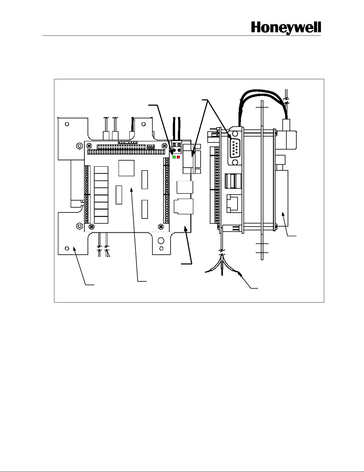
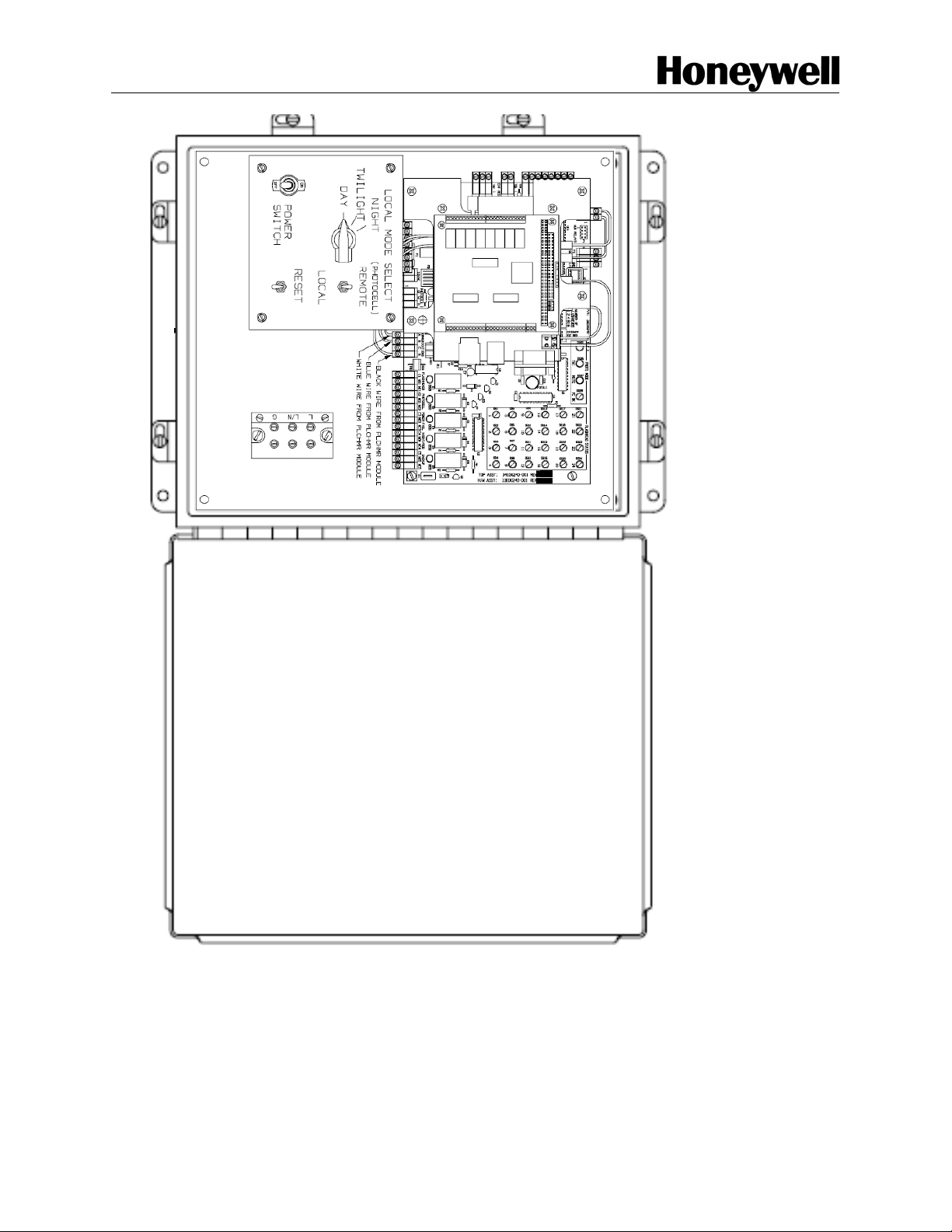
Figure 2.2-2 Master Controller with PLCHMR Module Installed
PLC Health Monitoring & Reporting Sys 2-4 Manual EPM40002083-001 Rev -
Page 13
Airport Systems
NO
NO
NC
C
NC
C
NO
+
AC
NC
C
AC
-
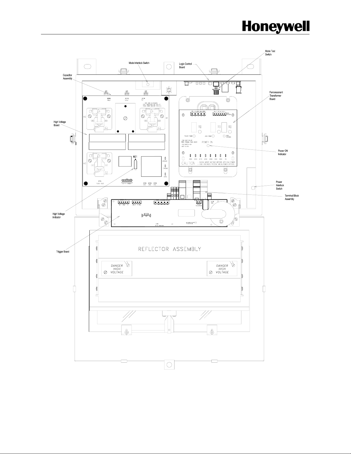
Figure 2.2-3: Model SGF-60E Flash Head
PLC Health Monitoring & Reporting Sys 2-5 Manual EPM40002083-001 Rev -
Page 14

Airport Systems
Safety Precautions
The following general safety precautions must be observed during all phases of operation,
service, and repair of this equipment. Failure to comply with these precautions or with
specific warnings elsewhere in this manual violates safety standards of design,
manufacture, and intended use of this equipment. Honeywell assumes no liability for the
customer’s failure to comply with these requirements, as listed below.
1. Any interruption of the protective grounding conductor (inside or
outside the instrument) or disconnecting the protective earth ground
terminal is likely to make this equipment dangerous. Intentional
interruption is prohibited.
2. Whenever it is likely that the ground protection has been impaired, the
equipment must be made inoperative by removing AC line power, and
then shall be secured against any unintended operation.
3. Ensure that only fuse / Breakers with the required rated current and of
the specified type (normal blow, time delay, etc.) are used for
replacement. The use of repaired fuses and the short-circuiting of fuse
holders must be avoided.
4. Electrical energy available at many points may result in personal injury
or death if touched. Any adjustment, maintenance, and repair of the
opened equipment while power is applied shall be avoided as much as
possible, however some maintenance described in this manual is
performed with power supplied to the equipment while protective
covers are removed. When repair with power applied is unavoidable,
only a skilled person who is aware of the hazard involved shall carry
out maintenance. Do not attempt internal service or adjustment unless
another person, capable of rendering first aid and resuscitation, is
present.
5. Do not install, substitute parts or perform any unauthorized
modification to the equipment.
6. Make sure the input voltage selection on the Ferroresonant
transformer assembly matches the line voltage before applying power
to the unit.
Capacitors inside the equipment may still be charged after the equipment has
been disconnected from its power source, even though the equipment was
designed to drain charge from the capacitors when power is removed. Do not put
hands or tools in the Flash-head if the High Voltage Indicator neon lamp NE1 is
ON, which is located on the High Voltage Circuit Board. (Refer to Figure 2.2-3)
7. Do not confuse the High Voltage Indicator NE1, with the POWER ON
Indicator located on the Ferro resonant Transformer Assembly. It is
possible for the High Voltage Indicator NE1 to be ON After the main
AC power to the unit is turned OFF (POWER ON Indicator is OFF). If
this happens, the energy stored in the capacitor Assembly must be
discharged before performing maintenance.
PLC Health Monitoring & Reporting Sys 2-6 Manual EPM40002083-001 Rev -
Page 15

Airport Systems
8. Capacitor Discharge Procedure. Attach one end of the capacitor
discharge tool to chassis ground first, then the other end to any of the
relay terminals. Hold for 3 seconds, or until the indicator turns off.
PLC Health Monitoring & Reporting Sys 2-7 Manual EPM40002083-001 Rev -
Page 16

Airport Systems
This system uses lethal voltages in the Flash-head. Unless absolutely
necessary, do not attempt to service or adjust the equipment with AC
line power applied.
Safety interlock switches are provided in the Flash-head enclosure to
interrupt main AC power to the power supply. These interlock switches
are activated when the Flash-head door is opened in a conventional
manner. No interlock is provided when other means of access are
used. Do not tamper with the interlocks by opening or shorting the
terminals.
The POWER ON Indicator is ON when the Ferroresonant Transformer is
powered. If the POWER ON Indicator is OFF, Line input AC power may
still be present in the system.
WARNING!
AC LINE VOLTAGE IS STILL PRESENT WHEN INTERLOCKS ARE
ACTIVATED. DISCONNECT POWER AT THE MAIN AC CIRCUIT
BREAKERS BEFORE INSPECTING OR SERVICING, UNLESS
ABSOLUTELY NECESSARY TO PERFORM MAINTENANCE WITH
POWER ON.
WARNING!
Flash tubes in this lighting system produce brilliant flashes of light
containing some ultraviolet radiation that can cause temporary or
permanent eye damage.
DO NOT LOOK DIRECTLY AT THE FLASH-HEAD WHILE IT IS IN
OPERATION.
PLC Health Monitoring & Reporting Sys 2-8 Manual EPM40002083-001 Rev -
Page 17

Airport Systems
2.3 Specifications
Electrical Input:
PLCHMR Module .................................................................................... 3 Watts. 5 VDC.
Mechanical Properties:
PLCHMR Module
Weight.............................................................................................2 pounds (4.4 kg)
Dimensions ......................................5.6"w (142mm) x 5.7"h (145mm) x 2"d (51mm)
Operating Environment:
Operating Temperature ............................................................................. -55ºC to +55ºC
Humidity...........................................................................................95% relative humidity
System Operating Status Indicators:
PLCHMR, DC line power present .............................. Green LED POWER ON Indicator
PLC Health Monitoring & Reporting Sys 2-9 Manual EPM40002083-001 Rev -
Page 18

Airport Systems
SECTION 3. INSTALLATION & POWER UP
WARNING!
Modifications to the Power Supply are required for certain applications.
Remove input power at circuit breakers and discharge capacitors with
an approved grounding rod before attempting any necessary
modifications.
3.1 Unpacking
Carefully unpack each item and remove any internal packing material from the
PLCHMR. Carefully check the supplied materials with the PLCHMR bill of materials.
There are many small items that should be supplied inside clear plastic bags, verify
each of these bags contain the proper amount of parts per the bill of materials. Report
any shortages of materials immediately to the Honeywell Technical Support.
Examine each item for obvious physical damage. Report any claims to the carrier
immediately. Pertinent information such as installation drawings, schematics,
interconnection drawings, and operation manuals are included in the carton. The
upgraded 8051 micro-controllers (MCU) replacements for the master control and each
flash head are in a separate package(s) inside the carton. Do not remove 8051 MCUs
from their respective packaging until you are ready to install them.
3.2 User Supplied Tools
PC computer with RS232 serial port,
Serial port parameters: 115200 baud, 8 data bits, no parity, 1 stop bit.
Terminal Emulator – MS Windows Hyper Terminal, Tera Term
Screwdriver ¼:” slot-type
Screwdriver 1/16” slot-type
Small Phillips screwdriver
DB9 to DB9 Female/Female RS2232 Null Modem Serial Interface Cable (Radio
Shack Model 03044 Catalog # 55010600 or equivalent)
3.2.1 Master Controls Switch Setting For Installation
Set Master Controller switches (Shown in Figure 2.2-2) as follows:
POWER SWITCH --------------------------------------------------------------------------- OFF
LOCAL / REMOTE Switch ------------------------------------------------------------ LOCAL
MODE Switch -------------------------------------------------------------------------------- DAY
The Master Controller has the following control switches (Figure 2.2-2):
PLC Health Monitoring & Reporting Sys 3-1 Manual EPM40002083-001 Rev -
Page 19

Airport Systems
• POWER SWITCH: Toggle switch that turns input AC line power on/off in the Master
Controller. Does not affect AC power to the Flash-heads. Input voltage is present
at terminal block PB1, even with the power switch turned off.
• RESET Switch: Momentary pushbutton that resets the Master Controller. Switch
must be held for about one second to activate.
• REMOTE / LOCAL Mode Switch: Two-position toggle switch that permits manual
(local) selection of the flash intensity level using the DAY / TWILIGHT / NIGHT
rotary switch. In normal (remote) operation, permits automatic operation controlled
by the Ambient Light Sensor photocell.
• DAY / TWILIGHT / NIGHT Switch: Three-position rotary switch that allows manual
selection of three light intensities of the system (DAY = high, TWILIGHT =
intermediate, and NIGHT = low). The REMOTE / LOCAL Mode Switch must be in
the LOCAL position to use this switch.
3.2.2 Power Configuration
The PLCHMR input voltage selection is set at the factory prior to shipping.
3.3 Installation
3.3.1 Installation Overview
The installation has four major activities:
First, replace the Master controller’s MCU with the one MCU provided by the kit
Second, mount and wire the PLCHMR module.
Third, replace the MCU in each Flash-head’s digital control board with the MCU
provided by the kit.
Fourth, the PLCHMR’s site specific configuration table must be edited to match
the configuration of the high intensity strobe system; this activity is described in
Section 3.7.
The following sub-sections feature detailed instructions for completing the installation
outlined above.
3.3.2 SGC-60 Master Controller MCU Upgrade
The installation kit provides one new MCU P/N 40002085-001 to replace the old MCU
P/N 40000328-001. It is important to install the MCU with the proper orientation since,
more often than not installing a MCU backwards will result in damage to the chip and/or
surrounding circuitry. First note the location of pin 1. To find pin 1 look for a small
rectangular notch on one of its short ends this denotes the top side of MCU; the first pin
counter-clockwise from this notch is pin 1
. The MCU is pressed into a socket. The
PLC Health Monitoring & Reporting Sys 3-2 Manual EPM40002083-001 Rev -
Page 20

Airport Systems
MCU’s socket has a notch along the outside edge on one of the short sides this is the
top side of the socket.
CAUTION!
Do not use excessive force when you remove or install the chip
from/into its socket. Excessive force can bend or damage the MCU
Pins or the socket.
Step 1
Gently remove the old MCU using a small flat head screwdriver to pry it free of its
socket. Set aside the old MCU.
Step 2
Carefully place the new MCU in the empty socket with top of the MCU and pin 1
in the same locations as noted earlier. Inspect all of MCU’s pins checking that
each pin is inserted into its respective contact and that none of the pins of have
"roll under" or "bend out" of the socket.
Step 3
Carefully press the new MCU into the empty socket until it is firmly seated on the
socket.
Step 4
Place the old MCU into the new MCUs empty shipping container.
A detailed drawing showing the location of the MCU in the Master Controller is shown in
Figure 3.3-1.
PLC Health Monitoring & Reporting Sys 3-3 Manual EPM40002083-001 Rev -
Page 21

Airport Systems
Replace existing
MCU PN40000328 with
new MCU PN40002085
40000328-001
Location of 4
Screws to be
removed for the
PLCHMR Module
Standoffs
Figure 3.3-1 Model SGC-60 Master Controller with MCU High-lighted
PLC Health Monitoring & Reporting Sys 3-4 Manual EPM40002083-001 Rev -
Page 22

Airport Systems
3.3.3 PLCHMR Module Installation
The installation kit provides a PLCHMR module P/N 40002083 that is mounted inside
the Master Controller Enclosure. This module is mounted to four 2.5” high standoffs
and has five (5) wires to connect to the Master Controller board.
3.3.3.1 PLCHMR Module 2.5” Standoff Installation
Remove and save the four (4) 6-32 screws that secure the Master Controller to the enclosure’s
bottom panel (Refer to
used in a later step to secure the PLCHMR module mounting plate to the standoffs.
Figure 3.3-1 for exact screw locations). The four saved screws will be
3.3.3.2 PLCHMR Module Power Supply Connections
The PLCHMR module receives 16VDC power from Terminal Block-8 located on the top left
hand corner of the Master Controller PCB as shown in
locations of the two positions on the plug-in terminal with respect to the +16 and GND Labels
shown on the Master Controller PCB. Remove the two position plug-in terminal and loosen both
of the plug-in terminal’s screw sufficiently to install the PLCHMR module’s red and black wires.
The red wire should be inserted into the screw terminal position labeled #2 as shown
Figure 3.3-2. Note the orientation and
Figure
3.3-3 which connects to the +16 contact on the Master Controller PCB. The black wire should
be inserted into the screw terminal position labeled #1 as shown
to the GND contact on the Master Controller PCB.
Figure 3.3-3 which connects
PLC Health Monitoring & Reporting Sys 3-5 Manual EPM40002083-001 Rev -
Page 23

Airport Systems
Output Relay
Terminal Blocks
TB8
Red
Black
PLCHMR
Module
TB-5
Figure 3.3-2 PLCHMR Module Mounted on and Wired to Master Controller
PLC Health Monitoring & Reporting Sys 3-6 Manual EPM40002083-001 Rev -
Page 24

Airport Systems
Black Wire
Red Wire
Figure 3.3-3 Terminal Block- 8 +16V - Red and GND –Black Wire Connections
3.3.3.3 PLCHMR Module Mount
The PLCHMR module mounts to the four 2.5” high standoffs that were installed per directions in
Section 3.3.3.1. Note the location and orientation of the PLCHMR module as shown in
Figure
3.3-2 relative to the Master Controller. Oriented the PLCHMR module and place it
approximately as shown per
position PLCHMR power supply plug-in with its mating header block on the Master Controller.
Carefully position the PLCHMR module so that the four (4) mounting plate holes line-up with
four tapped bores in the 2.5” standoff. Secure the mounting plate to the standoff by installing
the four (4) 6-32 screws removed during the Section 3.3.3.1 activities.
Figure 3.3-2 on the 2.5” high standoffs. Then re-connect the two
3.3.3.4 PLCHMR Module StrobeGuard Control and Status Network Connections
The PLCHMR module connects to the StrobeGuard Control and Status Network via
Terminal Block-5 which is located near the bottom center of the Master Controller PCB as
shown in
with their orientation and locations relative to the four position plug-in terminal connected to the
Master Controller. Remove the four position plug-in terminal. Install the White, Blue, and Black
PLCHMR’s network wires as directed:
Figure 3.3-2. Before starting this task, note any existing wiring connections along
a) Loosen the plug-in terminal’s screw labeled #1 as shown in
insert the PLCHMR module’s White wire into terminal position along with maintaining
any existing wiring connections.
PLC Health Monitoring & Reporting Sys 3-7 Manual EPM40002083-001 Rev -
Figure 3.3-4 sufficiently to
Page 25

Airport Systems
b) Next, loosen the plug-in terminal’s screw labeled #2 as shown in Figure 3.3-4
sufficiently to insert the PLCHMR module’s Blue wire into this terminal position along
with maintaining any existing wiring connections.
c) Finally, sufficiently loosen the plug-in terminal’s screw labeled #4 as shown in
and insert the PLCHMR module’s Black wire into the terminal position while
3.3-4
maintaining any existing wiring connections.
Reinstall the plug-in terminal onto its corresponding fixed mating header located on the Master
Controller.
Figure
1 2 3 4
Black WireWhite Wire
Blue Wire
Figure 3.3-4 StrobeGuard Control & Status Network Wiring Connections
3.3.4 SGF-60-E Flash-head Digital Controller MCU Upgrade
The installation kit provides new MCUs P/N 40002084-001 to replace all existing old
MCUs P/N 40000324-001 in Flash Head Logic Control Board. See Figure 2.2-3 for the
location of Logic Control Board in the Flash Head Enclosure. It is important to install the
MCU with the proper orientation since more often than not installing a MCU backwards
will result in damage to the chip and/or surrounding circuitry. First note the location of
pin 1. To find pin 1 look for a small rectangular notch on one of its short ends this
denotes the top side of MCU; the first pin counter-clockwise from this notch is pin 1
.
PLC Health Monitoring & Reporting Sys 3-8 Manual EPM40002083-001 Rev -
Page 26

Airport Systems
The MCU is pressed into a rectangular socket. This socket has a notch along the
outside edge on one of the short sides this is the top side of the socket.
CAUTION!
Do not use excessive force when you remove or install the chip
from/into its socket. Excessive force can bend or damage the MCU
Pins or the socket.
Step 1
Gently remove the old MCU using a small flat head screwdriver to pry it free of its
socket. Set aside the old MCU.
Step 2
Carefully place the new MCU in the empty socket with top of the MCU and pin 1
in the same locations as noted earlier. Inspect all of MCU’s pins checking that
each pin is inserted into its respective contact and that none of the pins of have
been "rolled under" or "bent out" of the socket.
Step 3
Carefully press the new MCU into the empty socket until it is firmly seated on the
socket.
Step 4
Place the old MCU into its replacement’s empty shipping container.
A detailed drawing showing the location of the MCU in the Flash-Head’s Digital Master
Controller is shown in Figure 3.3-5.
PLC Health Monitoring & Reporting Sys 3-9 Manual EPM40002083-001 Rev -
Page 27

Airport Systems
40000324-001
Figure 3.3-5 MCU Location on Flash Head Digital Logic Controler
PLC Health Monitoring & Reporting Sys 3-10 Manual EPM40002083-001 Rev -
Page 28

Airport Systems
3.4 Flash Head Status Reporting Relay Installation Wiring
The PLCHMR features eight (8) configurable status reporting outputs. Each output
connects to a form-c relay via three screw terminal connections. Each screw terminal
connection is uniquely tied to one of the relay’s contacts. In accordance with Figure
3.4-1:
1) Terminal labeled #1 connects to the normally-open contact
2) Terminal labeled #2 connects to the common contact
3) Terminal labeled #3 connects to the normally-closed contact,
Typically each discrete alarm reporting connections is made to the site’s alarm
monitoring system uses terminals 1 & 2. Using the typical connection ensures that a
fail/fault indication is reported in the event that power is interrupted to the SG-60 High
Intensity Strobe Light System.
Each relay’s state is controlled uniquely by its software Tier Reporting Mechanism
(TRM). The TRM is software configurable and enables the operator via a menu to
combine tier related flash-heads into a group that can be associated with a TRM. (See
Section 3.7.3 for additional details on software configuration)
The two operating states (activated/deactivated) of each relay represent the state of its
corresponding TRM. The TRM’s two states are Flash/OK and Fail/Fault. The TRM
state FLASH/OK represents a normal operation alarm level and is indicated by an
activated relay. The TRM state Fail/Fault represents an abnormal operation alarm level
and is indicated by a deactivated relay.
For example:
Assume that all the flash-heads on tier #1 are operating normally when some event
causes a tier’s flash-head to malfunction. While all of the flash-heads on tier 1 are ok,
TRM #1 is set to FLASH/OK and relay #1 is activated. After the fault event occurs
causing a flash-head on the tier to malfunction, then TRM #1 would automatically
change to the Fail/Fault state which would de-activate relay #1.
An activated relay cause the normally-open contact to be closed allowing any signal
applied to the common contact(#2) to appear on the normally-open contact (#1). For a
deactivated relay the normally-close contact is closed allowing any signal applied to the
common contact (#2) to appear normally-closed contact (#3).
PLC Health Monitoring & Reporting Sys 3-11 Manual EPM40002083-001 Rev -
Page 29

Airport Systems
Relay 1
Relay 2
Relay 3
Relay 4
Relay 5
Relay 6
Relay 7
Relay 8
-
1
2
3
1
2
3
1
2
3
1
2
3
1
2
3
1
2
3
1
2
3
1
2
3
R104-V2 0896
http://www.Tri-M.com
Tri-M Engineering
Figure 3.4-1 PLCHMR's Output Relay connection Diagram
Digital Inputs
Do Not Use
PLC Health Monitoring & Reporting Sys 3-12 Manual EPM40002083-001 Rev -
Page 30

Airport Systems
3.5 Final Installation Check
Before applying power to the equipment, perform the procedures in the following
sections. If any test does not pass, please consult Sections 3.3.3.2 and 3.3.3.4 in this
manual or call Honeywell Technical Support at (805) 581-5591.
3.5.1 Preliminary
1. Verify that all AC input power circuit breakers are turned off.
2. Check that the MCU on the Master Controller’s printed circuit boards is
properly seated in its socket.
3. Check that any user-installed wiring does not interfere with relay operation
when covers are closed.
4. Check that replacement MCUs have been installed in all Flash-heads.
Check that all Flash-head covers are shut properly for a weather-tight seal
with all latches closed.
5. Set Master Controller switches as follows:
POWER SWITCH ------------------------------------------------------------------ OFF
LOCAL / REMOTE Switch --------------------------------------------------- LOCAL
MODE Switch ----------------------------------------------------------------------- DAY
3.5.2 Verify Correct Wiring from the PLCHMR Module to Master Controller
Check that power supply and StrobeGuard Network connectors on the printed circuit
boards are properly seated in their sockets (Re-Verify that Sections 3.3.3.2 and 3.3.3.4
were performed correctly).
3.6 Power Up and System Tests
During the power up of the system, there are two LED lights, which will be checked to
verify correct operation and installation. The following is a description of all the
indicators on PLCHMR.
3.6.1 PLCHMR Status Indicators
• Power Status Indicators (Figure 2.2-1)
Red LED after power-up indicates Single Board Computer Fault
Green LED indicates Power is OK
3.6.2 System Power Up
All switches and indicators listed in this section are in the Master Controller, except for
the external system circuit breakers.
PLC Health Monitoring & Reporting Sys 3-13 Manual EPM40002083-001 Rev -
Page 31

Airport Systems
1. Verify POWER SWITCH is turned OFF.
2. Verify LOCAL / REMOTE switch is set to LOCAL.
3. Verify MODE switch is set to DAY.
4. Turn on circuit breaker to apply power to Master Controller.
5. Turn on circuit breaker to apply power to Flash-heads.
6. Turn POWER SWITCH to ON.
7. Verify that the Master Controller LED test sequence has started (See
EPM-00001152 - Installation and Operating Guide for High Intensity
Obstruction lighting). The test sequence will exercise every LED and relay
(e.g. it will quickly sweep through the Flash-head Status LEDs in red and
green mode).
After the test sequence completes, the Flash-head status LEDs for the
selected number of Flash-heads shall be lit red then change to green as
the Flash-heads report (DS1 - DS24, Figure 3.6-1 Item 4).
8. After 1 minute, verify the number of Flash-head status LEDs (DS1 - DS24,
Figure 3.6-1 Item 4) that are lit green matches the total number of white
Flash-head lights (including AOL) on the tower (if there are n Flash-heads
on the tower, Flash-head status LEDs DS1 - DSn shall be lit green). Verify
that the remaining unused Flash-head status LEDs (DSn+1 - DS24) are
turned off.
9. After all the flash-heads report good (green), check the Master Control
board’s relay monitoring LEDs which should display following:
i. DS29-DS32 GREEN,
ii. DS33 OFF (DS29 - DS33, Figure 3.6-1 Item 5.) Verify Photocell
status LED DS28 (Figure 3.6-1, Item 3) is lit green.
iii. Verify Day Mode LED DS25 (Figure 3.6-1, Item 3) is lit red, and
the Twilight and Night LEDs (DS26 and DS27 respectively Figure
3.6-1, Item 3) are not lit.
iv. Hold down the RESET switch for approximately 1 second and
verify the LED test sequence has restarted.
PLC Health Monitoring & Reporting Sys 3-14 Manual EPM40002083-001 Rev -
Page 32

Airport Systems
Wait 1 minute and measure the voltage between TB1-1 and TB1-2 to verify the voltage
is 12-18 VAC. Repeat steps 7 - 10 to assure proper recovery after reset.
Figure 3.6-1 Master Controller Circuit Board
PLC Health Monitoring & Reporting Sys 3-15 Manual EPM40002083-001 Rev -
Page 33

Airport Systems
Note: Before performing any tests of the Flash Head
Reporting Relay wiring the system must be configured
using the PLCHMR System Maintenance and
Configuration Menus.
3.7 PLCHMR System Maintenance and Configuration Menus
3.7.1 PLCHMR System Maintenance & Configuration Menus Overview
The PLCHMR system must be configured as part of the on-site installation. The
PLCHMR’s maintenance menus are used to view and modify the site specific
configuration data. The maintenance menus use a text window interface along with a
command entry prompt. The command entry prompt is posted at the bottom of terminal
window and is marked with “maint>”. Configuration data in the maintenance menus
contains information about the site’s lights, its reporting mechanism, and the facility
information. The site’s light configuration data contains information on how many lights,
which tiers the lights are located, and height above ground level. The reporting
configuration will specify if the reports are to be made via Ethernet or relays. The facility
information will include: the owner, contact number, address, FCC number, Altitude,
Longitude, and Latitude.
The maintenance menu system has a hierarchical structure which begins with the
Health Monitoring System (HMS) home maintenance menu (see Figure 3.7-2). The
home maintenance menu is the initial menu presented after the maintenance login is
completed. The home maintenance menu can be recognized by the “HMS
Maintenance Menu” title along with its four numbered menu items (See Figure 3.7-3).
PLC Health Monitoring & Reporting Sys 3-16 Manual EPM40002083-001 Rev -
Page 34

Airport Systems
Figure 3.7-1 PC to PLCHMR RS-232 Serial Port Interface Cable Connections
PLC Health Monitoring & Reporting Sys 3-17 Manual EPM40002083-001 Rev -
Page 35

Airport Systems
Press 1
Press 25
HMS Light Configuration Menu
Lamp_ID Tier_Lvl Height Facing_Dir Priority
1) 1 1 151 NW 1
2) 1 1 152 SE 2
3) 1 1 151 SW 1
25) Exit
HMS Maintenance Menu
1) Light Configuration
2) Report Configuration
3) Facility Information
4) Exit
Press 2
HMS Report Configuration Menu
Current Report Method: Relays + ETHERNET
1) NONE – Change report method to none
2) Relays – Change report method to relays
3) ETHERNET – Change report to ethernet
4) Relays & ETHERNET – Change report method to include both
5) Exit
Press 1
Press 5
Press 3
Press 9
HMS Facility Configuration Menu
1) OWNER
2) CONTACT NUMBER
3) ADDRESS LINE 1
4) FCC NUMBER
5) Altitude
7) Longitude
8) Latitude
9) Exit
HMS Modify Light Menu
1) Lamp ID: 1
2) Tier Level: 1
3) Height : 151 Feet AGL
4) Direction: NW
6 Clear All fields
Press 7
7)Exit
maint>1
Figure 3.7-2 HMS Maintenance Menu Hierarchy
The following is a detailed set of instructions for navigating and utilizing PLCHMR’s
maintenance menu system.
3.7.2 HMS Maintenance Menu Login
Access to the Maintenance Mode menus is restricted. A login id and password are
used to control access to the Maintenance Mode Menus. To gain access to the
maintenance mode menu use the following steps:
a) Connect one of the PC/Laptop’s serial ports to the PLCHMR’s serial port using a
female/female null modem serial interface cable as shown in Figure 3.7-1 (Radio
Shack Model 03044 Catalog # 55010600 or equivalent). The PLCHMR’s serial
port connection requires a DB-9 female connector.
b) On the PC/Laptop start a terminal emulator. Either HyperTerminal or Tera Term
is a suitable terminal emulator.
c) Configure the PC/Laptop’s terminal emulator’s serial port parameters to:
i) 115200 baud,
ii) 8 data bits,
PLC Health Monitoring & Reporting Sys 3-18 Manual EPM40002083-001 Rev -
Page 36

Airport Systems
iii) no parity,
iv) 1 stop bit.
d) Apply power and wait for login prompt. If power is already applied and a login
prompt is not shown press the enter key.
e) After the login prompt “login >” is displayed then type “maint” and wait for the
password prompt.
f) At the password prompt “password>” type “grimes” and wait for Home
Maintenance Window to be displayed (See Figure 3.7-3 ).
HMS Maintenance Menu
1) Light Configuration
2) Report Configuration
3) Facility Information
4) Exit Maintenance Mode
maint>
Command
Prompt
Menu Title
Menu Item
Figure 3.7-3 HMS Maintenance Menu
3.7.3 HMS Light Configuration Menu
The Light Configuration menu displays the current light configuration and allows the
user to modify the configuration lines by selecting a line number at the User Prompt
(See Figure 3.7-4). The Light Configuration menu can be recognized by the “HMS Light
Configuration Menu” title along with its 24 numbered rows of light data. The light
configuration menu is a table with six columns and 25 rows. The first column contains
the row number the remaining five columns have a unique heading. Each row
represents the location, orientation and priority data for a particular Flash head as
identified by the number in the Lamp Id column its row.
The column heading definitions are:
i. Lamp_ID – The unique address or ID# as set on Flash Head’s digital logic
board SW3. The maximum value for this entry is 24.
ii. Tier_Lvl – The tier or level number for the Flash Head defined s. Typically the
top tier of flash heads is numbered 1. The maximum value for this entry is 8.
Each Tier_Lvl is associated with a Tier Report Mechanism (TRM) which
controls the state of its reporting relay. The status of Tier_Lvl #1 is reported
via relay #1. Up to 24 flash heads could be assigned to one tier. Typically 3-
PLC Health Monitoring & Reporting Sys 3-19 Manual EPM40002083-001 Rev -
Page 37

Airport Systems
4 flash heads are assigned to a tier as this would represent the physical
installation of the flash heads on one tier of a tower.
iii. Height – The height as measured from ground level of the obstruction/tower.
iv. Facing_Dir – Nearest facing cardinal compass direction of the Flash Head.
System defines eight (8) valid cardinal directions and they are:
i. N
ii. NW
iii. E
iv. SE
v. S
vi. S
vii. SW
viii. W
ix. NW
v. Priority – Maintenance Priority associated with Flash Head. The range of
valid values is 0-25. Typically a value of 1 is used to represent the highest
priority maintenance issue.
HMS Light Configuration Menu
Lamp_ID Tier_Lvl Height Facing_Dir Priority
1) 1 1 151 NW 1
2) 2 2 152 SE 2
3) 3 2 153 SW 1
4) 4 3 164 N 1
5) 0 0 0 0
6) 0 0 0 0
7) 0 0 0 0
8) 0 0 0 0
9) 0 0 0 0
10) 0 0 0 0
11) 0 0 0 0
12) 0 0 0 0
13) 0 0 0 0
14) 0 0 0 0
15) 0 0 0 0
16) 0 0 0 0
17) 0 0 0 0
18) 0 0 0 0
19) 0 0 0 0
20) 0 0 0 0
21) 0 0 0 0
22) 0 0 0 0
23) 0 0 0 0
24) 0 0 0 0
25) Exit
maint>
Figure 3.7-4 HMS Light Configuration Menu
To edit the contents of a specific row in the HMS Light Configuration Menu, enter the
row number and press the enter key. This action will bring up the HMS Modify Light
PLC Health Monitoring & Reporting Sys 3-20 Manual EPM40002083-001 Rev -
Page 38

Airport Systems
Menu (see Figure 3.7-5. Once in the Modify Light Menus select the menu item to edit
by entering the row number of the menu item and pressing enter.
To erase all configuration data for a specific light listed in the HMS Light Configuration
Menu enter the row number of the light. This action brings up the HMS Modify Light
Menu. Next input the number 6 followed by the “Enter” key. After clearing all data
values input the number 7 along with an “Enter” key to exit to the HMS Light
Configuration Menu. Selecting the “Exit” menu option commits any changes made in
that menu to memory.
HMS Modify Light Menu
1) Lamp ID: 1
2) Tier Level: 1
3) Height: 151 Feet AGL
4) Direction: NW
5) Priority: 1
6) Clear all fields
7) Exit
maint>l
Figure 3.7-5 HMS Modify Light Menu
3.7.4 PLCHMR Report Configuration Menu
The Report Configuration Menu displays the current reporting configuration and allows
the user to select one of four reporting methods (See Figure 3.7-6). Do not change this
setting.
PLC Health Monitoring & Reporting Sys 3-21 Manual EPM40002083-001 Rev -
Page 39

Airport Systems
HMS Report Configuration Menu
Current Report Method: RELAYS + ETHERNET
1) NONE - Change Report method to none.
2) RELAYS - Change Report method to relays.
3) ETHERNET - Change Report method to ethernet.
4) RELAYS+ETHERNET - Change Report method to include both.
5) Exit
maint>
Figure 3.7-6 HMS Report Confguration Menu
3.7.5 PLCHMR Facility Configuration Menu
The Facility Configuration menu displays data about the facility’s operator and its
location. With this menu the user may edit any data line by selecting its line number at
the User Prompt and pressing the enter key (See Figure 3.7-7). The Facility
Configuration menu can be recognized by the “HMS Facility Configuration Menu” title
along with its 9 numbered rows of facility data.
HMS Facility Configuration Menu
1) OWNER: Obstruction Lighting
2) CONTACT NUMBER: 937-484-2000
3) ADDRESS LINE 1: 550 State Route 55
4) ADDRESS LINE 2: Urbana Oh 43078
5) FCC NUMBER: 10108227
6) Altitude: 1500.00
7) Longitude: 40.16
8) Latitude: -83.8
9) Exit
maint>
Figure 3.7-7 HMS Facility Conguration Menu
PLC Health Monitoring & Reporting Sys 3-22 Manual EPM40002083-001 Rev -
Page 40

Airport Systems
3.7.6 Verify Local Mode Operation
All switches and indicators listed in this section are in the Master Controller.
3.7.6.1 Day Mode:
1. Verify MODE Switch is set to DAY.
2. Verify Day mode LED DS25 (Figure 3.6-1, Item 3) is lit red.
3. After about 6 seconds, verify all Flash-heads are flashing in sync and in
Day mode (maximum brightness).
4. Verify that the Flash-head Status LED for each Flash-head on the tower is
lit green (including any AOL). Unused Flash-head status LEDs shall be
off. (DS1 - DS24: Figure 3.6-1, Item 4)
5. Verify relay status LEDs DS29-DS32 are lit green, and DS33 is OFF.
(Figure 3.6-1, Item 5)
6. If you have a Dual (Red/White) System
, the Red Lights should be OFF.
3.7.6.2 Twilight Mode:
1. Set MODE Switch to TWILIGHT.
2. Verify Day and Night mode LEDs (DS25 and DS27 respectively Figure
3.6-1, Item 3) are unlit and the Twilight mode LED DS26 is lit red.
3. After 6 seconds, Verify all Flash-heads are flashing in sync and in Twilight
mode (medium brightness).
4. Verify that the Flash-head Status LED for each Flash-head on the tower is
lit green (including any AOL). Unused Flash-head status LEDs shall be
off. (DS1 - DS24: Figure 3.6-1, Item 4)
5. Verify relay status LEDs DS29 - DS32 are lit green, and DS33 is off.
(Figure 3.6-1, Item 5)
6. If you have a Dual (Red/White) System, the Red Lights should be OFF.
3.7.6.3 Night Mode
1. Set MODE Switch to NIGHT.
2.
3. Verify Day and Twilight mode LEDs (DS25 and DS26 respectively (Figure
3.6-1, Item 3) are unlit and Night mode LED DS27 is lit red.
4. Verify that the Flash-head Status LED for each Flash-head on the tower is
lit green (including any AOL). Unused Flash-head status LEDs shall be
off. (DS1 - DS24: Figure 3.6-1, Item 4)
PLC Health Monitoring & Reporting Sys 3-23 Manual EPM40002083-001 Rev -
Page 41

Airport Systems
5. Verify relay status LEDs DS29-DS31 are lit green, and DS32 and DS33
are off. (DS29 - DS33: Figure 3.6-1, Item, 5,)
6. If you have a White-Only System: After 6 seconds, Verify all Flash-heads
are flashing in sync and in Night mode (lowest brightness, ~1/8 second
duration bursts at 40 bursts per minute).
7. If you have a Dual (Red/White) System: Verify normal red night mode
operation.
(a) Verify that all Flash-heads are OFF
(b) Verify that all Red Lights are ON and flashing properly, and the Red
(c) Verify that LED DS36 (EXT RED READY) is lit green (See Item 10,
8. If you have a Dual (Red/White) System: Perform the following steps to
check white night backup operation.
Light Controller does not indicate any alarms in the top-most Red
Beacons.
Figure 3.6-1).
(a) Simulate a Top Red Beacon failure.
On a Honeywell 9LCA Series Control, this may be done with the B1
circuit breaker in the Control. Turn the B1 breaker off to activate
the 9LCA Beacon Failure Alarm, or toggle the breaker momentarily
to activate the 9LCA Flasher Bypass Alarm.
Other Redlight systems have different controls, and may require
removing Red Beacon power at the input power circuit breakers.
(b) Verify that the DS36 (External Red Ready) LED is OFF.
(c) Verify that the DS32 (Night/Red) LED is ON
(d) Verify that the DS33 (Backup) LED is ON
(e) Verify that all the Red Lights are OFF
(f) Verify that all Flash-heads are flashing in sync and in Night mode
(lowest brightness, ~1/8 second duration bursts at 40 bursts per
minute).
(g) Repair the simulated Red Beacon failure.
(h) Verify that DS36 (External Red Ready) LED is ON.
(i) Verify that the lighting system is still operating white strobes, and
not red-lights.
(j) Set the MODE switch to DAY. Wait for the Flash-heads to switch to
DAY mode (about 6 seconds). Set the MODE switch back to
NIGHT. Wait for the Flash-heads to switch to OFF mode (about 6
seconds).
(k) Verify normal red night mode operation per Step 6 above.
PLC Health Monitoring & Reporting Sys 3-24 Manual EPM40002083-001 Rev -
Page 42

Airport Systems
(l) If you have more than one Red Beacon at the top level, repeat the
simulated failure test for each Red Beacon.
PLC Health Monitoring & Reporting Sys 3-25 Manual EPM40002083-001 Rev -
Page 43

Airport Systems
SECTION 4. PRINCIPLES OF OPERATION
4.1 Overall Description
The PLCHMR is a product that consists of hardware and software to provide health
monitoring and remote reporting services. PLCHMR is integrated into the
StrobeGuard® System. The PLCHMR uses a single board computer; manufactured by
a respected industrial supplier of single board computers (SBC). The SBC provides
sufficient processor bandwidth and memory support the intended health monitoring and
reporting tasks. The SBC has an industry standard PC/104 bus to provide a common
interface bus for a variety of off-the-shelf daughter boards. Industry standard daughter
boards have been selected to provide the required input/output interfaces consistent
with the demand of customer provided monitoring systems. In addition the SBC
provides a 10/100 Ethernet interface and an RS-485 serial port interface. The PLCHMR
will use its RS-485 serial network connection to receive and process health status data
from the SGC-60. The RS-485 serial network bus will be referred to as the
StrobeGuard Control and Status Network (SCSN). SCSN will be used to send
commands and collect status data from each SGF-60 Flash Head connected to the RS485 network. The PLCHMR is collocated within the SGC-60 Master Controller
enclosure.
The PLCHMR reports each flash heads’ health status via discrete outputs. Each flash
heads’ discretely reported status data will be a Flash/Fail report. PLCHMR System
uses a uniquely configured relay output daughter board. This daughter board drives
logic inputs provide by the customer at the remote facility. The relay output daughter
board will provides 8 Form C relays to report the system’s status. Screw terminals on
the relay output board will enable setting the relay’s output voltage. The normally
closed relay contact will be used to report the fail condition.
The PLCHMR provides an interactive character based menu -oriented Maintenance
Mode Service (MMS). The MMS is accessed via the SBC’s Serial RS232 interface.
The MMS is an interactive character-oriented communications session. A PC based
client terminal service initiates a MMS session by logging onto the system as the “maint”
user. The MMS validates the “maint” user via a password; it proceeds to establish a
session with the client terminal service by initially presenting the Maintenance Mode
menu.
4.1.1.1 Power Supply
The PLCHMR receive 16VDC power from the Master Controllers TB8 terminal
connector. The 16VDC power is fed to a single output DC/DC Converter which
produces 5VDC for the SBC.
4.1.1.2 Communications
The PLCHMR monitors commands from the Master Controller and Flash Head status
reports via the RS485 serial link.
PLC Health Monitoring & Reporting Sys 4-1 Manual EPM40002083-001 Rev -
Page 44

Airport Systems
SECTION 5. MAINTENANCE
5.1 PLCHMR Module
The PLCHMR module requires no periodic maintenance.
PLC Health Monitoring & Reporting Sys 5-1 Manual EPM40002083-001 Rev -
Page 45

Airport Systems
SECTION 6. REPLACEMENT PARTS
Description Part Number
SGC-60 Master Controller
Master Controller Replacement MCU-------------------- 40002085-001
SGF-60-E Flash-head
Digital Controller, Replacement MCU-------------------- 40002084-001
PLCHMR Module
Module, Assembly -------------------------------------------- 40002083-001
PLC Health Monitoring & Reporting Sys 6-1 Manual EPM40002083-001 Rev -
Page 46

Airport Systems
SECTION 7. APPENDIX A – EXAMPLES
7.1 Light Configuration Examples
The HMS Light Configuration Menu provides the flexibility and configurability to address
most field installations. This section provides specific examples that demonstrate some
possible configuration values that are the results of choices made in the Light
Configuration Menu. The PLCHMR system has eight (8) relays that can report the
status of up to 24 Flash Heads. The Light Configuration menu enables the user to map
the status reporting from any combination of Flash Heads to any one or all 8 of the
relays. In section 3.4 it was declared that the relay’s state is controlled by the software
configured Tier Reporting Mechanism (TRM). Section 3.4 also indicated the TRM has
two states FLASH/OK and FAIL/FAULT. Software configuration of the TRM is
performed through the HMS Light Configuration Menu. Each TRM can be assigned
from zero to 24 Flash Heads. A Flash Head is assigned to a specific TRM via a
numeric entry in its corresponding Tier_Lvl column in the Light Configuration Menu. For
a TRM to activate its relay the status reported of all Flash Heads assigned to that tier
must be FLASH/OK. The TRM will deactivate its relay if any Flash Head assigned to it
reports a FAIL/FAULT status.
For instance consider the following example on how a system with 24 Flash Heads
could be configured:
In the following example consider a system with nine Flash Heads arrange on 3 physical
tiers as shown in Figure 7.1-1.
A typical configuration could use seven Tier Reporting Mechanisms TRMs. Each of the
top six Flash Heads could be assigned to its own individual TRM. The three lowest
Flash Heads would be assigned to one of the remaining TRMs. The Flash/Fail status
for the top six Flash Head would be collected by their assigned TRM and then reported
by a relay whose number identifies the tier or (TRM) number. This would result in the
top six Flash Heads having individualized status reports and the bottom three flash
Heads having a collective status report. The Light Configuration Menu setting would
appear as shown in Figure 7.1-2. An alternative view is presented in Figure 7.1-3 which
shows the individual groups Flash Head groups reporting status to their assigned TRM
which is connected to the reporting relay.
PLC Health Monitoring & Reporting Sys 7-1 Manual EPM40002083-001 Rev -
Page 47

Airport Systems
Tier 3
Tier 2
23Tier 1
56
9
8
1
Flash Head Installation
with 9 Flash Heads, installed on
three tiers (levels). Each tier has
three Flash Heads. Flash Heads
4
7
numbers correspond to the unique
ID or address set on the Flash
Head’s digital logic board switch
#3.
Flash
Head #
Figure 7.1-1 Tower Example with 9 Flash Heads on Three Physical Tiers
PLC Health Monitoring & Reporting Sys 7-2 Manual EPM40002083-001 Rev -
Page 48

Airport Systems
HMS Light Configuration Menu
Lamp_ID Tier_Lvl Height Facing_Dir Priority
1) 1 1 151 NW 1
2) 2 2 152 SE 1
3) 3 3 153 SW 1
4) 4 4 133 NW 2
5) 5 5 133 SE 2
6) 6 6 133 SW 2
7) 7 7 113 NW 5
8) 8 7 113 SE 5
9) 9 7 113 SW 5
10)
11)
12)
13)
14)
15)
16)
17)
18)
19)
20)
21)
22)
23)
24)
25) Exit
maint>
Figure 7.1-2 Light Configuration Menus Settings for 9 Lights and 7 Relay Outputs
PLC Health Monitoring & Reporting Sys 7-3 Manual EPM40002083-001 Rev -
Page 49

Airport Systems
FLASH
HEAD 1
FLASH
HEAD 2
FLASH
HEAD 3
FLASH
HEAD 4
FLASH
HEAD 5
Flash/Fail Status
Flash/Fail Status
Flash/Fail Status
Flash/Fail Status
Flash/Fail Status
TRM
#1
TRM
#2
TRM
#3
TRM
#4
TRM
#5
Relay
State
Relay
State
Relay
State
Relay
State
Relay
State
Relay #1
Relay #2
Relay #3
Relay #4
Relay #5
132
132
132
132
132
FLASH
HEAD 6
FLASH
HEAD 7
FLASH
HEAD 8
FLASH
HEAD 9
Flash/Fail Status
Flash/Fail Status
TRM
#6
&
7
8
9
TRM #7
Relay #6
Relay
State
Relay #7
Relay
State
132
132
Figure 7.1-3 System Configuration with 9 Flash Heads using 7 relays
PLC Health Monitoring & Reporting Sys 7-4 Manual EPM40002083-001 Rev -
Page 50

Airport Systems
A typical configuration would be to create eight tiers (or groups). Each tier would be a
collection of three Flash Heads. Each tier’s status would be collect by its assigned TRM
and then reported by the relay whose number identifies the tier or (TRM) number. The
Light Configuration Menu setting would appear as shown in Figure 7.1-4. An alternative
view is presented in Figure 7.1-5 which shows the individual groups Flash Head groups
reporting status to their assigned TRM which is connected to the reporting relay.
HMS Light Configuration Menu
Lamp_ID Tier_Lvl Height Facing_Dir Priority
1) 1 1 1510 NW 1
2) 2 1 1520 SE 1
3) 3 1 1530 SW 1
4) 4 2 1330 Nw 2
5) 5 2 1330 SE 2
6) 6 2 1330 SW 2
7) 7 3 1130 NW 2
8) 8 3 1130 SE 2
9) 9 3 1130 SW 2
10) 10 4 1030 NW 3
11) 11 4 1030 SE 3
12) 12 4 1030 SW 3
13) 13 5 930 NW 3
14) 14 5 930 SE 3
15) 15 5 930 SW 3
16) 16 6 830 NW 4
17) 17 6 830 SE 4
18) 18 6 830 SW 4
19) 19 7 530 NW 5
20) 20 7 530 SE 5
21) 21 7 530 SW 5
22) 22 8 230 NW 5
23) 23 8 230 SE 5
24) 24 8 230 SW 5
25) Exit
maint>
Figure 7.1-4 Light Configuration Menus Settings for 24 Light and 8 Relay Outputs
PLC Health Monitoring & Reporting Sys 7-5 Manual EPM40002083-001 Rev -
Page 51

Airport Systems
FLASH
HEAD 1
FLASH
HEAD 2
FLASH
HEAD 3
FLASH
HEAD 4
FLASH
HEAD 5
FLASH
HEAD 6
FLASH
HEAD7
FLASH
HEAD 8
FLASH
HEAD 9
FLASH
HEAD
10
FLASH
HEAD
11
FLASH
HEAD
12
Flash/Fail Status
Flash/Fail Status
Flash/Fail Status
Flash/Fail Status
&
1
20
3
TRM #1
&
4
5
6
Relay
State
TRM #2
&
7
80
9
Relay
State
TRM #3
&
10
11 0
12
Relay
State
TRM #4
Relay
State
Relay #1
Relay #2
Relay #3
Relay #4
FLASH
HEAD
13
FLASH
132
HEAD
14
FLASH
HEAD
15
FLASH
HEAD
16
FLASH
132
132
132
HEAD
17
FLASH
HEAD
18
FLASH
HEAD
19
FLASH
HEAD
20
FLASH
HEAD
21
FLASH
HEAD
22
FLASH
HEAD
23
FLASH
HEAD
24
Flash/Fail Status
Flash/Fail Status
Flash/Fail Status
Flash/Fail Status
&
13
14
15
TRM #5
&
16
17
18
TRM #6
&
19
20
21
TRM #7
&
22
23 0
24
TRM #8
Relay
State
Relay
State
Relay
State
Relay
State
Relay #5
Relay #6
Relay #7
Relay #8
132
132
132
132
Figure 7.1-5 System Configuration with 24 Flash Heads using 8 relays
PLC Health Monitoring & Reporting Sys 7-6 Manual EPM40002083-001 Rev -
 Loading...