

Page 1
Galaxy 2 Series Quick-start Guide
NOTE: It is strongly recommended that any personnel installing
a Galaxy 2 Series panel undertake appropriate training. A full
installation manual should be obtained from your branch.
A full technical installation manual will be given to each installer
at the training session. Additional manuals can be purchased
from your distributor.
Additionally, the installation manual is available from the
Honeywell Security website: www.honeywell.com/security
Variants
The Galaxy 2 Series is available as two different variants.
The variants are shown in the table below:
Model No of zones
on-board
2-20 12 20 22
2-44+ 12 44 22
*Excluding Master and Engineer
Zones
(MAX)
STD
Users*
Setup
In order to get the system up and running, mount the panel
and connect and address all peripherals as described
below, before finally powering the system.
Peripheral Wiring
The following peripherals can be connected to the panel:
RS485 Bus: Mk7 LCD Keypad/Keyprox; MAX
PSU; Ethernet Module; RF Portal.
NOTE: The system must be wired in a daisy-chain
configuration. Spur and star configurations must
not be used. The recommended cable used to
connect the RS485 (AB) line is twisted pair
screened cable (Belden 8723 equivalent).
However, for cable runs of less than 100m in
normal environments, standard 4-core cable can
be used.
Panel Peripheral
AUX+ +
AUX– –
A A
B B
RS485 Peripheral Wiring
ECP Bus (2–44+ only): 6160 Keypad/Keyprox; 5882H
RF receiver; ECP zone expander.
NOTE: Keypads can be wired to the control panel
independently, in series or in star configuration. The
maximum total cable length for peripherals connected to
this line is 100 m.
Panel
AUX+ + + (red) +12V I/P
AUX– – – (black) –
DO YV DO (yellow) DO
DI GU DI (green) DI
6160
Keypad
5800
Receiver
ECP Peripheral Wiring (2-44+ only)
3
; RIO;
ECP 8-Zone
Expander
Peripheral Addressing
The address on most peripherals is set by either jumpers or
a rotary switch. These must be set before the system is
powered up. See the instructions with the peripheral for
details.
The following table identifies the available peripheral
addresses:
Valid addresses
Peripheral G2-20 G2-44+
Mk7 Keypad
& Keyprox
MAX3** 0, 1, 2, 3 0, 1, 2, 3
RIO 2 2, 3, 4, 5
PSU 2 2, 3, 4, 5
RF Portal* 4, 5 4, 5
6160 Keypad - 0, 1, 2, 3
6160 Keyprox
Keypad
keyprox
5882H RF
Receiver*
ECP 8-zone
expander
0, 1, 2, 3 0, 1, 2, 3
- 0, 1
- 4, 5
- 4, 5
- 2, 3, 4
Peripheral Addresses
* Adding one wireless receiver allows all zones to become
wireless, up to the maximum for the panel type. Adding a second
receiver allows for greater reception coverage.
**
The number of MAX3 s available on the system is limited to 1.
Mains Supply Wiring
This product is not suitable for installation, maintenance or
connection by the user. A competent, qualified engineer,
with for example NSI approval, must carry out installation
and maintenance.
Warning: A means of isolation from the mains supply
must be provided within two metres of the
control panel. Where live and neutral
supplies can be identified, a fused spur with
a 3A fuse must be fitted on the live circuit.
Where live and neutral circuits cannot be
readily identified, 3A fuses must be fitted to
both circuits.
Connect the wires to the mains terminal block in the panel
as follows:
• Blue (neutral) – connect to terminal N
• Green/Yellow (earth) – connect to terminal E
• Brown (live) – connect to terminal L
1
Page 2
Zone Address Format
1 0 1 5
Bus Line Zone number
Galaxy zones are given addresses rather than zone
numbers. This is because the zones are grouped into
blocks of 8 called ‘RIOs’. The left hand digit is the data
bus line number. The second and third digits are the RIO
address, which can be 00 to 05. The right hand digit is the
individual zone number on the RIO (1-8). Each zone can
also be given a text descriptor. By default, it is blank.
There are 2 RIOs on board the panel (Line 1). The first
RIO (00) has 4 zones addressed 1001 to 1004 and the
second RIO (01) has 8 zones addressed 1011 to 1018.
All individual zone programming is done in menu 52.
Zone Wiring
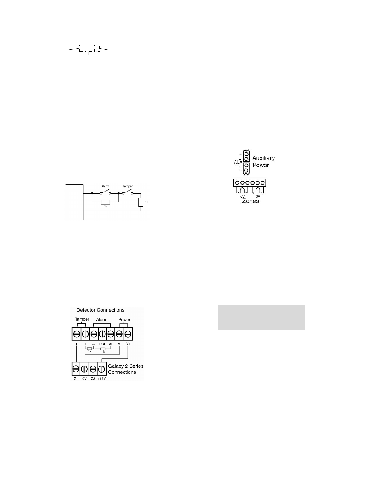
The default zone configuration is 1k double-balanced as
shown below:
RIO Address
Output Wiring
The on-board outputs are all open-collector switched
negative. The load that is to be controlled by an output
should be connected between +12 V and the output
terminal.
Note: Output 1002 is set up by default as a 16-ohm
speaker driver. That means that it gives an AC audio
signal. This is not suitable for driving a normal sounder,
relay, LED, etc. However, the mode can be changed in
menu 51.15 if a normal output mode is needed.
Power Wiring
Auxiliary power can be drawn from the terminals shown.
The‘common’ terminals on the zones are 0 volts.
Any unused hardwire zones should always have a 1k
resistor wired across the zone terminals to terminate them.
The configuration for the zones and the resistance values
used can be reprogrammed from menu option 51.46 =
Parameters. Zone Resistance. The cable run on each
zone should be no more than 100 m.
Detector wiring
Detectors are wired to a zone as in the following diagram:
Output Address Format
Galaxy outputs are addressed in the same way as the
zones. However, there are only 4 outputs on each RIO.
The on-board outputs are all on RIO 0 and have the
addresses 1001 to 1004. RIO 1 on-board does not have
programmable outputs.
All individual output programming is done in menu 53.
Operation
Default User Codes
Default User Code: 1234
Default Engineer Code: 112233
First Boot-up
After all the peripherals have been wired and addressed,
apply power to the system. The keypads will configure and
show the panel type and software version. A typical
banner display is shown below.
Galaxy 44 V1.4
09:00 SAT 01 JAN
Menu Access Operation/Navigation
Only valid codes can access the Galaxy 2 Series menu
options. Type the code then press ent to access the menu.
Data entry is via the 0-9 function keys and the * and # on
the keypad.
The A> and <B keys are cursor or scroll keys and are used
to scroll through options in menus.
The ent key is used to enter a PIN code and to accept
screen information.
The esc key is used to cancel or exit from the current
operation.
NOTE: Users cannot view or access options for which
they are not authorised.
2
Page 3
How to get into Engineer Mode
Entry to Engineer Mode is authorised by a user in menu
option 48 = Engineer Access. Following this, the
engineer will have 5 minutes in which to enter his code.
When the engineer code is entered four things happen:
• All system tampers become isolated.
• All fault signalling is suppressed and indications are
silent.
• The engineer is given access to the full menu.
• The banner message is changed to indicate Engineer
Mode.
How to get out of Engineer Mode
To bring the system back out of Engineer Mode and
reinstate all the tampers, from the banner, the engineer
enters his code, but then presses the esc key rather than the
ent key. A 30-minute window is activated to allow the
engineer back into engineer mode without re-authorisation
by a user.
NOTE: If there are faults or tampers that have not been
restored, the panel will not exit from Engineer Mode. Press
esc to get back to the Engineer banner and then restore the
faults as detailed below. Once all faults and tampers are
restored, the panel can be brought out of Engineer mode.
How to Set and Unset
To Full Set the system, the user types their code then
presses the A key.
To Part or Night Set the system, the user types their code
then presses the B key. The user now has a choice of
pressing 1 to Part Set or 2 to Night Set.
To Unset the system, the user types their code then presses
ent. Alternatively, presenting a valid tag at a prox reader
or pressing the ‘Off’ key on a wireless keyfob can also
unset the system.
NOTE: In the UK, on DD243 compliant systems, a user
code cannot normally be used to unset the system. A prox
tag must be used. A code can only be used after an alarm
condition has occurred. This can be altered in menu
51.55.3=Restrict Keypad.
How to Cancel an Alarm, Tamper or Fault
Alarms, tampers and fault conditions can be cancelled by
entering a user code at a keypad. When the code is entered,
the conditions activated will be displayed. The scroll keys
(A> and <B) can be used to view all the events. Alarm
conditions can also be cancelled by pressing the ‘Off’
button on a wireless keyfob or by presenting a valid tag at
a proximity reader. However, a code will need to be
entered at a keypad in order to see and restore the alarms.
How to Restore an Alarm, Tamper or
Fault
Alarms, tampers and fault conditions will be restored
provided:
• The cause has cleared and then;
• A user with sufficient authority has typed their code at
the banner and viewed the condition on a keypad (any user
if Technistore is used).
If a user is unable to restore an alarm, then a manager or
engineer will have to be called.
Code Tampers
When enabled (see menu option 51.14 = Parameters.
Lockouts), and 10 wrong codes are entered in succession,
the device is locked. The lockout lasts for 2 minutes. After
a further 10 wrong code entries, a tamper is logged and a
signal is given. The device is again locked out for 2
minutes.
NOTE: Wireless keyfobs and tags can still operate.
Conversely, if a wrong tag is presented to a prox or an
invalid wireless fob is activated for the same number of
attempts, the prox and receiver devices are locked out, but
the keypads still operate.
Menu Summary
All the functions of the panel are accessible via the menu.
The top level of the menu is summarised below:
10 = Setting 20 = Display 30 = Test
11 = Omit Zones 21 = Zone Status 31 = Walk Test
12 = Timed Set 22 = View Log 32 = Output Test
13 = Part Set 23 = System Version
14 = Night Set 24 = Print
15 = Chime 26 = Trace
40 = Modify 50 = Engineer 1 60 = Engineer 2
41 = Time/Date 51 = Parameters 61 = Diagnostics
42 = Users 52 = Zones 62 = Full Test
44 = Mobile Nos. 53 = Outputs 63 = Options
47 = Remote Access 56 = Comms
48 = Level 3 Access 57 = System Print
58 = Keypad Groups
Each of these headings has its own sub options that can be
accessed using the ent, esc and scroll keys. The most
important menu options are summarised below:
63=Options
Start with this menu to select Group mode. Group mode
needs to be turned on if the system is to be split into
independent groups.
51=Parameters
In this menu, all the general parameters are set up, such as
Bell time, entry/exit time and reset levels. Select each
particular parameter by using the scroll keys (A> and <B)
and press ent to edit the settings for that parameter. Some
parameters can have different settings for each group.
52=Zones
In this menu, the function of each individual zone input
can be customised. Select the zone address using the scroll
keys (A> and <B) and press ent to access the parameters
3
Page 4

for that zone. Wireless detectors are configured within the
programming of the individual zones in this menu.
53=Outputs
In this menu, the function of each individual output can be
customised. Select the output address using the scroll keys
(A> and <B) and press ent to access the parameters for
that output.
56=Communications
In this menu, Alarm signalling to the ARC can be
configured. First, select the module type from the list using
the scroll keys (A> and <B) then press ent to access the
parameters for that module. The account number,
Telephone nos/IP address and format need to be
programmed to enable basic communications.
A sub option called parameters allows all signalling
parameters to be configured. This include part set
signalling options and signalling delays. 42=Users
In this menu, use the further sub menu called User Codes
to program the attributes of individual users. Each user on
the system can have the following assigned: PIN code,
Prox tag, Type (authority level) and Group.
To program a prox tag, select the user required then select
option 6 Prox Tags. On a keyprox, press 1 & A together
then present the user’s tag to the prox symbol at the
bottom of the keypad. The number will enter
automatically. Press ent to save.
For use on a MAX
3
simply type in the number printed on
the max tag.
The tag can then be used for setting and unsetting.
Holding tag briefly in front of prox symbol/max reader
will unset, holding tag for 3 seconds in front of prox
symbol will begin setting procedure as long as there are no
outstanding resets required.
Text programming
Communications
Built-in Comms
The Galaxy 2 Series has a built-in telephone dialler. The
incoming telephone line should be wired to the ‘Line In A
B’ terminals. The alarm panel should always be the first
device on the phone line. Additional extensions should be
connected to the serial terminals marked ‘A B’ next to the
phone symbol. This will allow the panel to snatch the line
when it needs to dial out.
All comms programming is done in menu 56.1.
GSM Module Option (2–44+ only)
As an option, a GSM comms module can be added to provide a
backup communication path in the event of failure of the
telephone line. Please see the installation instructions supplied
with the GSM module.
All programming for the GSM module is done in menu 56.6
External Stand-alone Dialler
An additional external dialler can be connected to the
Galaxy 2 Series by way of the Trigger header. The
connection comprises a cable that plugs on to the 12-way
header in the centre of the main PCB. The other end of the
cable connects to the terminal board which contains screw
terminals for each core. The pins of the 12-way header
have the following functions:
Certain options allow text to be entered. In these options,
text is entered in the similar way to text messaging on
mobile phones, by repeated presses of the number keys to
select the appropriate letters. The keys have the following
functions in text programming mode:
Key Output
1 & - 1 @ ‘ ( ) full stop, comma, # * +
2 A, B, Ä, Å, Æ, C, 2, a, b, c, ä, å, æ
3 D, E, F, 3, d, e, f
4 G, H, I, 4, g, h, i
5 J, K, L, 5, j, k, l
6 M, N, O, Ö, ø, 6, m, n, o, ö
7 P, Q, R, 7, p, q, r, s
8 T, U, V, 8, t, u, v, ü
9 W, X, Y, 9, w, x, y, z
0 <space>, 0
esc Cancels the edit without saving changes
ent Save string entry and exit
* Deletes character to left of cursor
# Deletes character at the cursor
The +12 V supply can supply a maximum of 100 mA but
this reduces the total capacity of the panel’s PSU by the
same amount.
The function of the trigger outputs can be programmed in
menu 53, under the output addresses 0001 to 0008.
Dual-path Signalling
When more than one comms device is fitted to the panel,
one can be programmed as the main comms device and the
other can be programmed as the backup/fail-safe that will
only signal if the main device fails (line fault). This is
controlled by menu 56.7. Each device can be given a
hardware priority. Setting the priority to 0 means that
device will never signal. Setting it to 1 means that it will
always signal. Setting it to 2 means that it will only signal
if the main device fails.
4
Page 5

Panel Specifications
Physical
2-20: Metal box - 1.2 mm steel Width: 300 mm
Height: 255 mm
Depth: 115 mm
Weight: 3.9 kg
(with mains transformer and PCB installed)
2-44+ : Metal box - 1.2 mm steel Width: 370 mm
Height: 320 mm
Depth: 85 mm
Weight: 4.5 kg
(with mains transformer and PCB installed)
Operating temperature -10
Electrical
PSU Type A
Mains Input: 230 V ac (+10%, -15%), 50 Hz
Back-up Battery (not supplied):
2-20: Up to 12 Ah 12 V Sealed Lead-Acid (metal encl.).
2-44+: Up to 17 Ah 12 V Sealed Lead-Acid (metal encl.)
Panel current consumption: 120 mA (max)
2-20
PSU Max total load: 1.0 A (nominal temp. and
mains supply
2-44+
PSU Max total load: 1.4 A (nominal temp. and
mains supply
2-20
Grade 2 Rating: 600 mA
Max continuous ripple voltage: 0.5V at max load.
2-44+
Grade 2 Rating: 1.0 A
Max continuous ripple voltage: 0.5V at max load
Individual 12 V outputs
Bell +12 V 500 mA max
Both Aux+ combined 500 mA max
Trigger Header +12 V 100 mA max
Switched Outputs
Trigger Header Outputs Can sink 30 mA each
Bell Trigger 1003 Can sink 500 mA max
Strobe Trigger 1004 Can sink 500 mA max
Trig output 1001 Can sink 300 mA max
Speaker Output 1002 8 to 32 ohms or 100 mA in
switched DC mode
o
C to +40oC
Fuses
Mains 200 mA, 20 mm Anti-surge (IEC 127)
Battery (F1) 1 A, 20 mm Anti-surge
AUX (F2) 500 mA, 20 mm Anti-surge
Bell (F3) 500 mA, 20 mm Anti-surge
5
Page 6

EN50131 Compliance
This product is suitable for use in systems designed to comply
with PD6662:2004 and EN50131-1:2004.
Security Grade - 2
Environmental Class - II
Alarm Transmission System - 2 (options A, B, C & X)
Power Supply Type - A
This product is also suitable for use in alarm systems designed to
comply with EN50131-1:1997.
Security Grade - 2
Environmental Class - II
Alarm Transmission System - D2, T2, A2, I0, S0
Power Supply Type - A
Compliance and Approvals
The Galaxy 2 Series is compatible with the relevant parts
of the following standards:
• 99/05/EEC R&TTE Directive
• EN50130-5:1998 Alarm systems. Environmental test methods
Public Switched Telephone Network (PSTN) Approval
The equipment has been approved to Council Decision 98/482/EC for
Pan -European single terminal connection to the Public Switched
Telephone Network (PSTN). However due to differences between the
individual PSTNs provided in different countries the approval does not,
of itself, give an unconditional assurance of successful operation on every
PSTN network termination point. In the event of problems contact the
equipment supplier in the first instance. The Galaxy 2 Series is designed
to interwork with the following networks:
Austria France Italy Norway
Belgium Greece Liechtenstein Portugal
United Kingdom Denmark Iceland Luxembourg
Spain Finland Ireland The Netherlands
Sweden
NOTE: Contact the equipment supplier before using the Galaxy 2 Series
on any network not listed.
HONEYWELL SECURITY LIMITED
WARRANTY
Honeywell Security, and its divisions, subsidiaries and affiliates
(“Seller”), 165 Eileen Way, Syosset, New York, 11791, warrants its
products to be in conformance with its own plans and specifications and
to be free from defects in materials and workmanship under normal use
and service for 24 months from the date stamp control on the product.
Seller’s obligation shall be limited to repairing or replacing, at its option,
free of charge for materials or labour, any product that is proved not in
compliance with Seller’s specifications or proves defective in materials or
workmanship under normal use and service. Seller shall have no
obligation under this Limited Warranty or otherwise if the product is
altered or improperly repaired or serviced by anyone other than
Honeywell factory service. For warranty service, return product
transportation prepaid to:
Honeywell Security, 6 Aston Fields Road, Whitehouse Industrial
Estate, Runcorn, Cheshire WA7 3DL
THERE ARE NO WARRANTIES, EXPRESS OR IMPLIED, OF
MERCHANTABILITY, OR FITNESS FOR A PARTICULAR
PURPOSE OR OTHERWISE, WHICH EXTEND BEYOND THE
DESCRIPTION ON THE FACE HERE OF. IN NO CASE SHALL
SELLER BE LIABLE TO ANYONE FOR ANY CONSEQUENTIAL
OR INCIDENTAL DAMAGES FOR BREACH OF THIS OR ANY
OTHER WARRANTY, EXPRESS OR IMPLIED, OR UPON ANY
OTHER BASIS OF LIABILITY WHATSOEVER, EVEN IF THE LOSS
OR DAMAGE IS CAUSED BY THE SELLER’S OWN NEGLIGENCE
OR FAULT.
Seller does not represent that the products it sells may not be
compromised or circumvented; that the products will prevent any
personal injury or property loss by burglary, robbery, fire or otherwise; or
that the products will in all cases provide adequate warning or protection.
Customer understands that a properly installed and maintained alarm may
only reduce the risk of a burglary, robbery, fire or other events occurring
without providing an alarm, but it is not insurance or a guarantee that
such will not occur or that there will be no personal injury or property
loss as a result.
CONSEQUENTLY, SELLER SHALL HAVE NO LIABILITY FOR
ANY PERSONAL INJURY, PROPERTY DAMAGE OR OTHER LOSS
BASED ON A CLAIM THE PRODUCT FAILED TO GIVE
WARNING. HOWEVER, IF SELLER IS HELD LIABLE, WHETHER
DIRECTLY OR INDIRECTLY, FOR ANY LOSS OR DAMAGE
ARISING UNDER THIS LIMITED WARRANTY OR OTHERWISE,
REGARDLESS OF CAUSE OR ORIGIN, SELLER’S MAXIMUM
LIABILITY SHALL NOT IN ANY CASE EXCEED THE PURCHASE
PRICE OF THE PRODUCT, WHICH SHALL BE THE COMPLETE
AND EXCLUSIVE REMEDY AGAINST SELLER.
This warranty replaces any previous warranties and is the only warranty
made by Seller on this product. No increase or alteration, written or
verbal, of the obligations of this Limited Warranty is authorized.
Honeywell Security
Newhouse Industrial Estate (UK64)
Motherwell
Lanarkshire
ML1 5SB
UK
IG1-0036 Rev 1.0
6
 Loading...