

Page 1
Q7300A,C,D,G Series 2000
Commercial Thermostat Subbases
INSTALLATION INSTRUCTIONS
APPLICATION
The Q7300 Thermostat Subbases are used with T7300
Thermostats to provide electronic control of commercial
Table 1. Description of Q7300 Subbases.
Model Applications Thermostat Required Heat Cool Hookup Drawing
Q7300A Conventional T7300D, F 2 2 9-12
Q7300C Heat Pump T7300E, F 3 2 13-15
Q7300D Heat Pump T7300E, F 3 2 16
Q7300G Conventional T7300D, F 3 3 17
a
Depends on model.
RECYCLING NOTICE
If this control is replacing a control that contains
mercury in a sealed tube, do n
control in the trash
Contact your local waste management authority for
instructions regarding recycling and the proper
disposal of the old thermostat.
ot
place your old
INSTALLATION
When Installing this Product…
1. Read these instructions carefully. Failure to follow
the instructions can damage the product or cause a
hazardous condition.
2. Check the ratings given in the instructions and on
the product to make sure the product is suitable for
your application.
3. Installer must be a trained, experienced service
technician.
4. After completing installation, use these instructions
to check out the product operation.
24 Vac single or multistage heat pump or conventional
heating and cooling systems. Select models have terminals for LEDs and remote temperature sensors. Refer to
Table 1. All Q7300 Thermostat Subbases require a
common wire to the supply power.
Maximum Stages
a
Location
Subbase without Remote-Mounted
Temperature Sensor
Install the thermostat about 5 ft (1.5m) above the floor in
an area with good air circulation at average temperature.
See Fig. 1.
Do not install the thermostat where it can be affected by:
— drafts, or dead spots behind doors and in corners.
— hot or cold air from ducts.
— radiant heat from sun or appliances.
— concealed pipes and chimneys.
— unheated (uncooled) areas such as an outside wall
behind the thermostat.
Subbase with Remote-Mounted
Temperature Sensor(s)
If only the remote-mounted temperature sensor(s) is used
to sense and control room temperature, then install the
thermostat in an area that is accessible for setting and
adjusting the temperature and settings.
If both the subbase and remote-mounted temperature
sensor(s) are used to sense and control room temperature, then install the subbase about 5 ft above the floor in
an area with good air circulation.
® U.S. Registered Trademark
Copyright © 1996 Honeywell Inc. • • All Rights Reserved
X-XX UL
62-0135
Page 2
Q7300A,C,D,G SERIES 2000 COMMERCIAL THERMOSTAT SUBBASES
NO
NO
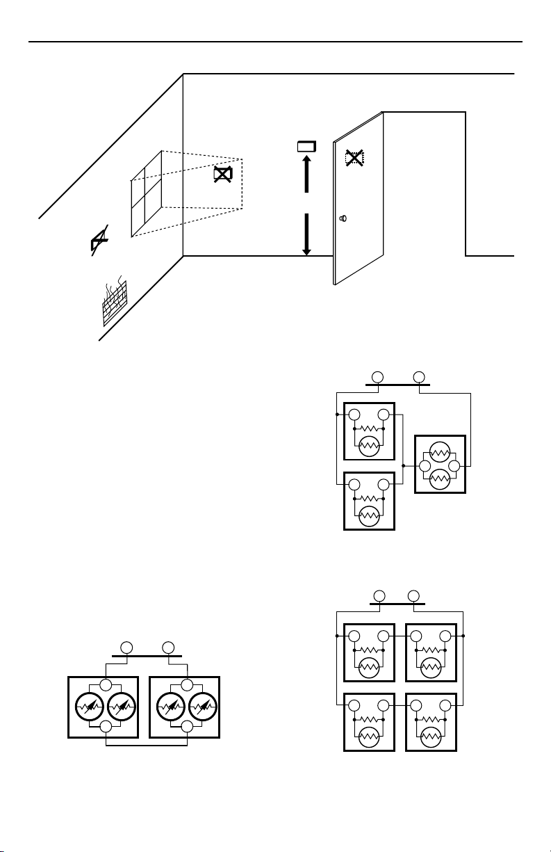
Fig. 1. Typical location of thermostat or remote-mounted sensor.
Install the remote-mounted sensor(s) about 5 ft (1.5m)
above the floor in an area with good air circulation at
average temperature. See Fig. 1.
Do not mount the sensor(s) where it can be affected by:
— drafts, or dead spots behind doors and in corners.
— hot or cold air from ducts.
— radiant heat from sun or appliances.
— concealed pipes and chimneys.
— unheated (uncooled) areas such as an outside wall
behind the thermostat.
If more than one remote sensor are required, they must be
arranged in a temperature averaging network consisting of
two, three, four, five or nine sensors. See Fig. 2 through 6.
IMPORTANT
To avoid electrical interference, which can cause
erratic performance, keep wiring runs as short as
possible and do not run thermostat wires
adjacent to the line voltage electrical distribution
systems. Use shielded cable (Belden type 8762
or equivalent for 2-wire and Belden type 8772 or
equivalent for 3-wire). The cable shield must be
grounded only at the controlled equipment case.
SUBBASE
TT
YES
5 FEET
(1.5 METERS)
Fig. 3. Two T7047C Sensors and one T7047G Sensor
providing temperature averaging network for
NO
M4823A
SUBBASE
TT
T7047C
TT
T7047G
T7047C
TT
TT
M4839
T7300/Q7300 Thermostat/Subbase.
SUBBASE
TT
T7047C
TT
T7047C
TT
T
T
Fig. 2. Two T7047G Sensors providing
temperature averaging network for
T7300/Q7300 Thermostat/Subbase.
62-0135
T7047GT7047G
T
T
M4838
T7047C
TT
Fig. 4. Four T7047C Sensors providing
temperature averaging network for
T7300/Q7300 Thermostat/Subbase.
T7047C
TT
M4840
2
Page 3
T7047G
T
T7047G
SUBBASE
TT
T7047G
T
T
T7047G
Q7300A,C,D,G SERIES 2000 COMMERCIAL THERMOSTAT SUBBASES
WALL
WIRES
THROUGH WALL
T
T7047G
WALL
ANCHORS
T
T
(2)
T
T7047C
T7047C
T7047C
T
T
SUBBASE
TT
T7047C
TT
T7047C
TT
T7047C
TT
M4841
TT
TT
TT
M4842
T
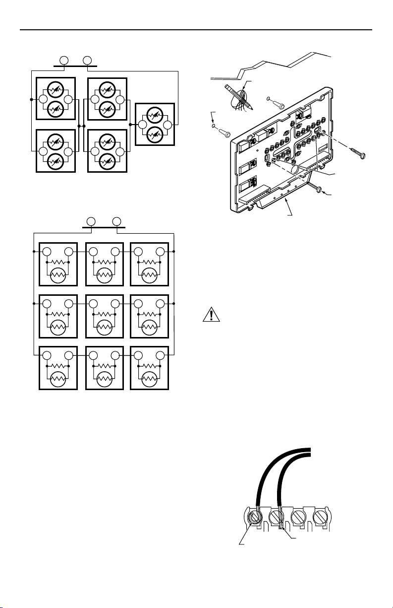
Fig. 5. Five T7047G Sensors providing
temperature averaging network for
T7300/Q7300 Thermostat/Subbase.
T7047C
TT
T7047C
TT
T7047C
TT
Fig. 6. Nine T7047C Sensors providing
temperature averaging network for
T7300/Q7300 Thermostat/Subbase.
Mounting Subbase
The subbase mounts horizontally on the wall or a 2 in. x 4 in.
wiring box. Position the subbase horizontally on the wall or
on a 2 in. x 4 in. wiring box.
쐃 Position and level the subbase or wallplate (for
appearance only). The thermostat functions properly
even when not level.
쐇 Use a pencil to mark the mounting holes. See Fig. 7.
쐋 Remove the subbase or wallplate from the wall and
drill two 3/16 inch holes in the wall (if drywall) as
marked. For firmer material such as plaster or wood,
drill two 7/32 inch holes. Gently tap anchors (provided) into the drilled holes until flush with the wall.
쐏 Position the subbase over the holes, pulling wires
through the wiring opening.
쐄 Loosely insert the mounting screws into the holes.
쐂 Tighten mounting screws.
MOUNTING
HOLES
MOUNTING
SCREWS
LEDS
M10237
Fig. 7. Mounting the subbase.
WIRING SUBBASE
All wiring must comply with local electrical codes and
ordinances. Follow equipment manufacturer wiring
instructions when available. Refer to Fig. 9 through 17 for
typical hookups. A letter code is located near each
terminal for identification.
CAUTION
Disconnect power before wiring to prevent
electrical shock or equipment damage.
쐃 Loosen the terminal screws on the subbase and
connect the system wires. See Fig. 8.
IMPORTANT
Use 18-gauge, solid-conductor color-coded
thermostat cable for proper wiring. If using 18gauge stranded wire, no more than ten wires can
be used. Do not use larger than 18-gauge wire.
쐇 Securely tighten each terminal screw.
쐋 Push excess wire back into the hole.
쐏 Plug the hole with nonflammable insulation to
prevent drafts from affecting the thermostat.
FOR STRAIGHT
FOR WRAPAROUND
INSERTION STRIP
7/16 IN. (11 MM).
Fig. 8. Proper wiring technique.
INSERTION STRIP
5/16 IN. (8 MM).
M4826
3
62-0135
Page 4
Q7300A,C,D,G SERIES 2000 COMMERCIAL THERMOSTAT SUBBASES
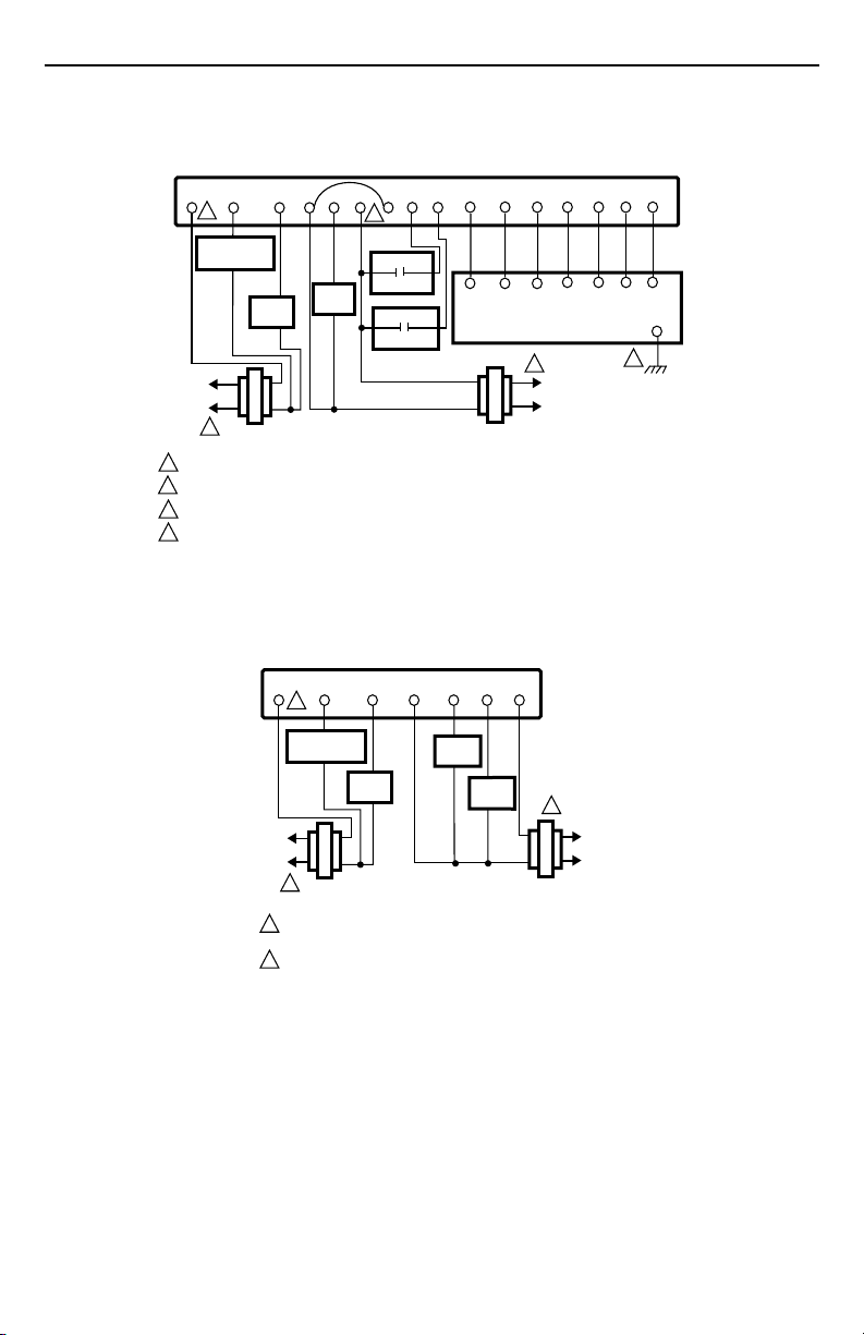
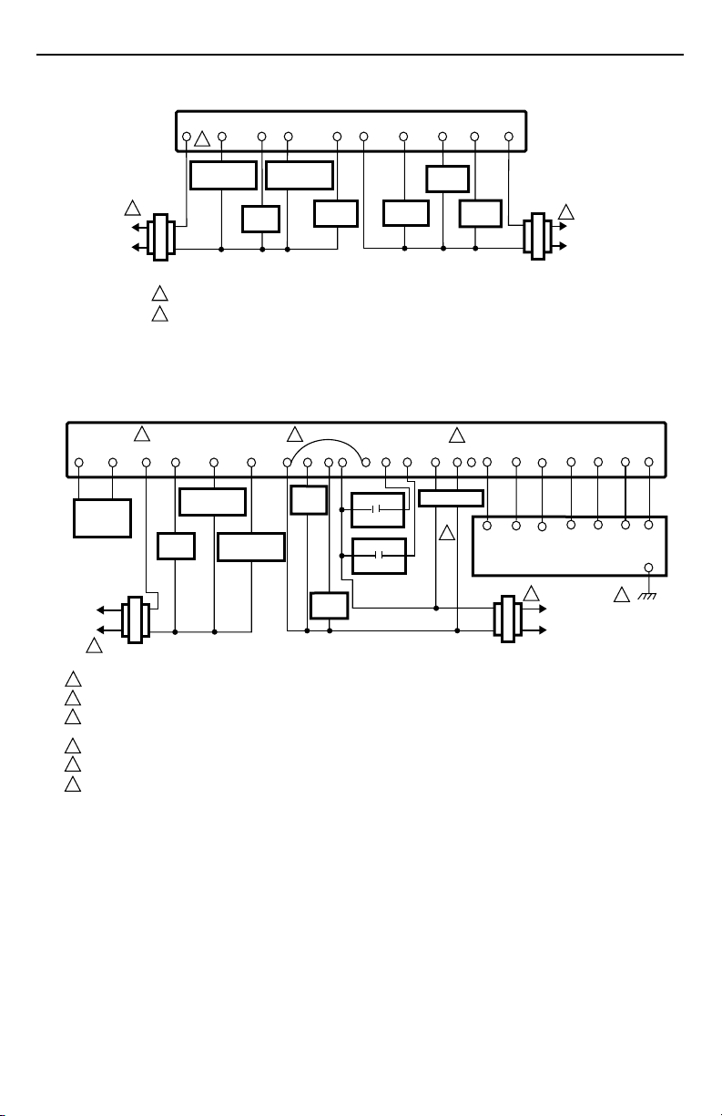
Typical Wiring Hookups
SUBBASE
C2
Y1 G X
RC
2
COMPRESSOR
CONTACTOR
FAN
RELAY
L1
(HOT)
L2
1
COOLING
1
2
3
4
TRANSFORMER
POWER SUPPLY. PROVIDE DISCONNECT MEANS AND OVERLOAD PROTECTION AS REQUIRED.
JUMPER RC TERMINAL TO RH TERMINAL WHEN INSTALLED ON A SYSTEM WITH ONE TRANSFORMER.
CONNECT GND TO EARTH GROUND.
INSTALL FIELD JUMPER BETWEEN X4 AND X TO POWER LEDS.
Fig. 9. Typical hookup of T7300D,F/Q7300A in one-stage heat and
one-stage cool conventional system with two transformers.
RC
2
W1
HEAT
RELAY
Y1 G X
RH
4
EQUIPMENT
MONITOR 2
EQUIPMENT
MONITOR 1
SUBBASE
X3 X1X4
C4 C3C5
CA2
CA4 CA3CA5
T7147 REMOTE COMFORT ADJUST MODULE
1
L1
(HOT)
L2
HEATING
TRANSFORMER
W2
RHW1
C1 T
CA1
M4939A
T
T
T
GND
3
62-0135
COMPRESSOR
CONTACTOR 1
FAN
RELAY
L1
(HOT)
L2
1
COOLING
TRANSFORMER
1
POWER SUPPLY. PROVIDE DISCONNECT MEANS AND
OVERLOAD PROTECTION AS REQUIRED.
2
JUMPER RC TERMINAL TO RH TERMINAL WHEN INSTALLED
ON A SYSTEM WITH ONE TRANSFORMER.
Fig. 10. Typical hookup of T7300D,F/Q7300A in two-stage heat and
one-stage cool conventional system with two transformers.
HEAT
RELAY 2
HEAT
RELAY 1
1
HEATING
TRANSFORMER
M10230
L1
(HOT)
L2
4
Page 5
AS AS
L1
(HOT)
L2
1
Q7300A,C,D,G SERIES 2000 COMMERCIAL THERMOSTAT SUBBASES
SUBBASE
Y1 G X
RC
2
COMPRESSOR
CONTACTOR 1
COOLING
TRANSFORMER
1
POWER SUPPLY. PROVIDE DISCONNECT MEANS AND OVERLOAD PROTECTION AS REQUIRED.
2
JUMPER RC TERMINAL TO RH TERMINAL WHEN INSTALLED ON A SYSTEM WITH ONE TRANSFORMER.
Fig. 11. Typical hookup of T7300D,F/Q7300A in two-stage heat and
two-stage cool conventional system with two transformers.
2
RC
Y1GX
FAN
RELAY
Y2
Y2
COMPRESSOR
CONTACTOR 2
5
W2
COOL
DAMPER
RH
W1
SUBBASE
BO
HEAT
DAMPER
W2
HEAT
RELAY 2
3
A2 A3A1X3 X1X4
HEAT
RELAY 1
C5
RHW1
HEATING
TRANSFORMER
C4
1
L1
(HOT)
L2
M10236
C1 T
C2
C3
T
COMPRESSOR
DISCHARGE
AIR
SENSOR
L1
(HOT)
L2
1
COOLING
TRANSFORMER
1
POWER SUPPLY. PROVIDE DISCONNECT MEANS AND OVERLOAD PROTECTION AS REQUIRED.
2
JUMPER RC TERMINAL TO RH TERMINAL WHEN INSTALLED ON A SYSTEM WITH ONE TRANSFORMER.
3
USE A1 AND A2 WHEN THE CONTACTS SHOULD BE NORMALLY CLOSED IN OCCUPIED MODE. USE A2 AND A3 WHEN
THE CONTACTS SHOULD BE NORMALLY OPEN IN OCCUPIED MODE.
4
CONNECT GND TO EARTH GROUND.
5
INSTALL FIELD JUMPER BETWEEN X4 AND X TO POWER LEDS.
6
USE ECONOMIZER INSTRUCTIONS FOR INSTALLATION DIRECTIONS.
CONTACTOR 1
FAN
RELAY
COMPRESSOR
CONTACTOR 2
Fig. 12. Typical hookup of T7300D,F/Q7300A in two-stage heat and
two-stage cool conventional system with two transformers.
HEAT
RELAY 2
HEAT
RELAY 1
EQUIPMENT
MONITOR 2
EQUIPMENT
MONITOR 1
ECONOMIZER
6
CA5
T7147 REMOTE COMFORT ADJUST MODULE
HEATING
TRANSFORMER
CA4
CA1
CA2
CA3
1
L1
(HOT)
L2
4
M4945A
T
T
GND
5
62-0135
Page 6
Q7300A,C,D,G SERIES 2000 COMMERCIAL THERMOSTAT SUBBASES
SUBBASE
AS AS
5
Y1 O G
X
R
E
B
W2
3
X3 X1X4
A2A1
C4 C3C5
T
C1 T
C2
FAN
EM. HT.
RELAY
RELAY
HEAT
RELAY 2
DISCHARGE
AIR
SENSOR
COMPRESSOR
CONTACTOR 1
COOL
CHANGEOVER
VALVE
1
POWER SUPPLY. PROVIDE DISCONNECT MEANS AND OVERLOAD PROTECTION AS REQUIRED.
2
USE ECONOMIZER INSTRUCTIONS FOR INSTALLATION DIRECTIONS.
3
USE A1 AND A2 WHEN THE CONTRACT SHOULD BE NORMALLY CLOSED IN OCCUPIED MODE.
CONNECT GND TO EARTH GROUND.
4
INSTALL FIELD JUMPER BETWEEN X4 AND X TO POWER LEDS.
5
HEAT
CHANGEOVER
VALVE
EQUIPMENT
MONITOR 2
EQUIPMENT
MONITOR 1
CA4 CA3CA5
T7147 REMOTE COMFORT ADJUST MODULE
ECONOMIZER
2
TRANSFORMER
CA2
M4946A
CA1
1
L1
(HOT)
L2
T
4
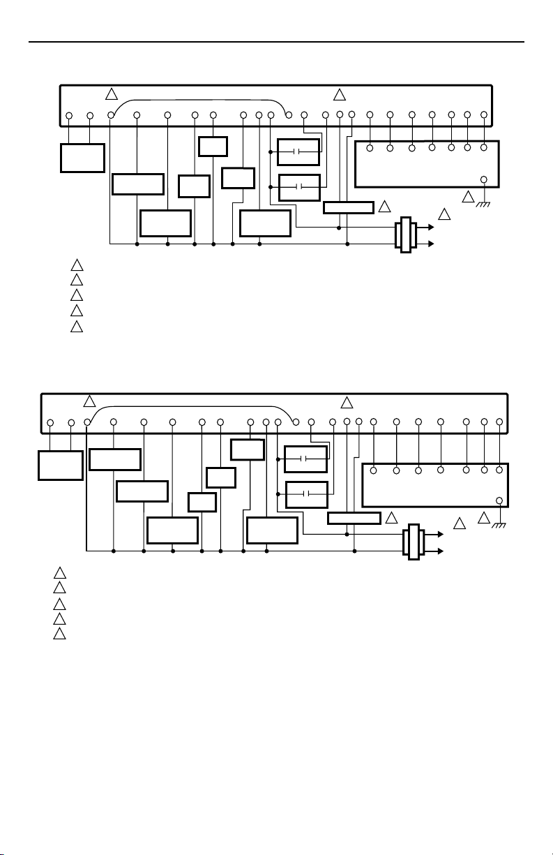
Fig. 13. Typical hookup of T7300E,F/Q7300C in two-stage heat and one-stage cool heat pump system.
SUBBASE
5
Y2
X
AS AS
DISCHARGE
AIR
SENSOR
COMPRESSOR
CONTACTOR 2
1
POWER SUPPLY. PROVIDE DISCONNECT MEANS AND OVERLOAD PROTECTION AS REQUIRED.
2
USE ECONOMIZER INSTRUCTIONS FOR INSTALLATION INSTRUCTIONS.
USE A1 AND A2 WHEN THE CONTACTS ARE NORMALLY CLOSE IN OCCUPIED MODE.
3
CONNECT GND TO EARTH GROUND.
4
INSTALL FIELD JUMPER BETWEEN X4 AND X POWER LEDS.
5
Y1 O G
COMPRESSOR
CONTACTOR 1
COOL
CHANGEOVER
VALVE
E
EM. HT.
RELAY
FAN
RELAY
W1
HEAT
RELAY 3
HEAT
CHANGEOVER
VALVE
B
R
EQUIPMENT
MONITOR 2
EQUIPMENT
MONITOR 1
X3 X1X4
3
A2A1
C4 C3C5
CA4 CA3CA5
T7147 REMOTE COMFORT ADJUST MODULE
ECONOMIZER
2
TRANSFORMER
CA2
C1 T
C2
CA1
1
L1
(HOT)
L2
M4947A
Fig. 14. Typical hookup of T7300E,F/Q7300C in three-stage heat and two-stage cool heat pump system.
GND
T
T
T
T
GND
4
62-0135
6
Page 7
Q7300A,C,D,G SERIES 2000 COMMERCIAL THERMOSTAT SUBBASES
SUBBASE
X
YO G
2
Y2
3
W3E
W2
RB
X1 X2L
HEAT
RELAY 3
HEAT
RELAY 2
HEAT
CHANGEOVER
VALVE
EQUIPMENT
MONITOR 2
EQUIPMENT
MONITOR 1
TRANSFORMER
1
M4940A
L1
(HOT)
L2
EM.
MODE
COMPRESSOR
CONTACTOR 1
1
POWER SUPPLY. PROVIDE DISCONNECT MEANS AND OVERLOAD PROTECTION AS REQUIRED.
2
EM. MODE IS ON CONTINUOUSLY IN EMERGENCY HEAT MODE.
3
EM. HT. RELAY CYCLES IN EMERGENCY HEAT MODE.
COMPRESSOR
CONTACTOR 2
COOL
CHANGEOVER
VALVE
EM. HT.
RELAY
FAN
RELAY
Fig. 15. Typical hookup of T7300E,F/Q7300C in three-stage heat and two-stage cool heat pump system.
SUBBASE
4
AS AS
DISCHARGE
AIR
SENSOR
1
POWER SUPPLY. PROVIDE DISCONNECT MEANS AND OVERLOAD PROTECTION AS REQUIRED.
2
USE A1 AND A2 WHEN THE CONTACTS SHOULD BE NORMALLY CLOSED IN OCCUPIED MODE. USE A2 AND A3 WHEN THE
CONTACTS SHOULD BE NORMALLY OPEN IN OCCUPIED MODE.
3
CONNECT GND TO EARTH GROUND.
4
INSTALL FIELD JUMPER BETWEEN X4 AND X TO POWER LEDS.
5
USE ECONOMIZER INSTRUCTIONS FOR INSTALLATION DIRECTIONS.
Y1 G
X R
COMPRESSOR
CONTACTOR 1
FAN
RELAY
COMPRESSOR
CONTACTOR 2
W3E
W2
HEAT
RELAY 3
HEAT
RELAY 2
W1
HEAT
RELAY 1
EQUIPMENT
MONITOR 2
EQUIPMENT
MONITOR 1
Y2
EM. HT.
RELAY
2
A2 A3A1X3 X1X4
ECONOMIZER
5
C4 C3C5
CA2
CA4 CA3CA5
T7147 REMOTE COMFORT ADJUST MODULE
1
TRANSFORMER
CA1
L1
(HOT)
L2
T
T
T
GND
3
M4948A
C1 T
C2
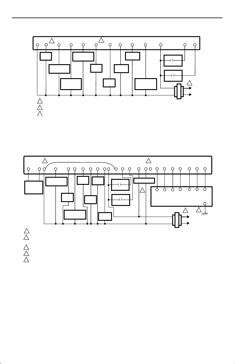
Fig. 16. Typical hookup of T7300E,F/Q7300D in three-stage heat and two-stage cool heat pump system.
7
62-0135
Page 8

Q7300A,C,D,G SERIES 2000 COMMERCIAL THERMOSTAT SUBBASES
SUBBASE
5
Y1 G X
RC RH
AS AS
DISCHARGE
AIR
SENSOR
1
2
3
4
5
6
2
COMPRESSOR
CONTACTOR 1
L1
(HOT)
L2
1
COOLING
TRANSFORMER
POWER SUPPLY. PROVIDE DISCONNECT MEANS AND OVERLOAD PROTECTION AS REQUIRED.
JUMPER RC TERMINAL TO RH TERMINAL WHEN INSTALLED ON A SYSTEM WITH ONE TRANSFORMER.
USE A1 AND A2 WHEN THE CONTACTS SHOULD BE NORMALLY CLOSED IN OCCUPIED MODE. USE A2 AND A3 WHEN CONTACTS
SHOULD BE NORMALLY OPEN IN OCCUPIED MODE.
CONNECT GND TO EARTH GROUND.
INSTALL FIELD JUMPER BETWEEN X4 AND X TO POWER LEDS.
USE ECONOMIZER INSTRUCTIONS FOR INSTALLATION DIRECTIONS.
FAN
RELAY
Y2
COMPRESSOR
CONTACTOR 2
COMPRESSOR
CONTACTOR 3
W3Y3
HEAT
RELAY 3
W2
HEAT
RELAY 2
W1
HEAT
RELAY 1
EQUIPMENT
MONITOR 2
EQUIPMENT
MONITOR 1
Fig. 17. Typical hookup of T7300D,F/Q7300G in three-stage heat and three-stage cool conventional system.
A.
Mounting Thermostat on Subbase
Mount the thermostat on the subbase after the subbase is
installed.
쐃 Engage tabs at the top of the thermostat and
subbase. Fig. 18.
쐇 Press lower edge of case to latch.
NOTE: To remove the thermostat from the wall,
first pull out at the bottom of the thermostat; then remove the top.
IMPORTANT
Refer to the thermostat installation instructions for
Installer Setup, Settings, Installer Self-Test and
Troubleshooting information.
ENGAGE TABS AT TOP OF THERMOSTAT AND SUBBASE OR WALLPLATE.
3
A2 A3A1X3 X1X4
ECONOMIZER
6
B.
PRESS LOWER EDGE OF CASE TO LATCH.
C4 C3C5
CA4 CA3CA5
T7147 REMOTE COMFORT ADJUST MODULE
1
HEATING
TRANSFORMER
L1
(HOT)
L2
C2
CA2
C1 T
CA1
M4949A
T
T
T
GND
4
Home and Building Control
Honeywell Inc.
Honeywell Plaza
P.O. Box 524
Minneapolis, MN 55408-0524
62-0135
62-0135 J.H. Rev. 12-96
Fig. 18 Mounting thermostat on subbase.
Home and Building Control
Honeywell Limited-Honeywell Limitée
155 Gordon Baker Road
North York, Ontario
M2H 2C9
8
M4824A
www.honeywell.com/building/components
 Loading...