

Page 1

Voyager™ 1200g/1202g
Single-Line Laser Bar Code Scanner
User’s Guide
Page 2

Disclaimer
Honeywell International Inc. (“HII”) reserves the right to make changes in specifications and other information contained in this
document without prior notice, and the reader should in all cases consult HII to determine whether any such changes have been
made. The information in this publication does not represent a commitment on the part of HII.
HII shall not be liable for technical or editorial errors or omissions contained herein; nor for incidental or consequential damages
resulting from the furnishing, performance, or use of this material.
This document contains proprietary information that is protected by copyright. All rights are reserved. No part of this document
may be photocopied, reproduced, or translated into another language without the prior written consent of HII.
2010-2013 Honeywell International Inc. All rights reserved.
Other product names or marks mentioned in this document may be trademarks or registered trademarks of other companies
and are the property of their respective owners.
Web Address:
Microsoft® Windows® and the Windows logo are trademarks or registered trademarks of Microsoft Corporation.
The Bluetooth® word mark and logos are owned by Bluetooth SIG, Inc.
Other product names or marks mentioned in this document may be trademarks or registered trademarks of other companies
and are the property of their respective owners.
www.honeywellaidc.com
Page 3

Product Agency Compliance - Voyager 1200g
USA
FCC Part 15 Subpart B Class B
This device complies with part 15 of the FCC Rules. Operation is subject to the following two conditions:
1. This device may not cause harmful interference.
2. This device must accept any interference received, including interference that may cause undesired operation.
This equipment has been tested and found to comply with the limits for a Class B digital device pursuant to part 15 of the
FCC Rules. These limits are designed to provide reasonable protection against harmful interference in a residential installation. This equipment generates, uses, and can radiate radio frequency energy and, if not installed and used in accordance with the instructions, may cause harmful interference to radio communications. However, there is no guarantee that
interference will not occur in a particular installation. If this equipment does cause harmful interference to radio or television
reception, which can be determined by turning the equipment off and on, the user is encouraged to try to correct the interference by one or more of the following measures:
• Reorient or relocate the receiving antenna.
• Increase the separation between the equipment and receiver.
• Connect the equipment into an outlet on a circuit different from that to which the receiver is connected.
• Consult the dealer or an experienced radio or television technician for help.
If necessary, the user should consult the dealer or an experienced radio/television technician for additional suggestions.
The user may find the following booklet helpful: “Something About Interference.” This is available at FCC local regional
offices. Honeywell is not responsible for any radio or television interference caused by unauthorized modifications of this
equipment or the substitution or attachment of connecting cables and equipment other than those specified by Honeywell.
The correction is the responsibility of the user.
Use only shielded data cables with this system. This unit has been tested with cables less than 3 meters. Cables greater
than 3 meters may not meet class B performance.
Caution: Any changes or modifications made to this equipment not expressly approved by Honeywell may void the FCC
authorization to operate this equipment.
UL Statement
UL listed: UL60950-1, 2nd Edition.
Canada
Industry Canada ICES-003
This Class B digital apparatus complies with Canadian ICES-003. Operation is subject to the following conditions:
1. This device may not cause harmful interference.
2. This device must accept any interference received, including interference that may cause undesired operation.
Conformité à la règlementation canadienne
Cet appareil numérique de la Classe B est conforme à la norme NMB-003 du Canada. Son fonctionnement est assujetti
aux conditions suivantes :
1. Cet appareil ne doit pas causer de brouillage préjudiciable.
2. Cet appareil doit pouvoir accepter tout brouillage reçu, y compris le brouillage pouvant causer un fonctionnement
indésirable.
C-UL Statement
C-UL listed: CSA C22.2 No.60950-1-07, Second Edition.
Page 4

Europe
The CE marking indicates compliance with the following directives:
• 2004/108/EC EMC
• 2011/65/EU RoHS (Recast)
In addition, complies to 2006/95/EC Low Voltage Directive, when shipped with recommended power supply. European
contact:
Hand Held Products Europe B.V.
Nijverheidsweg 9-13
5627 BT Eindhoven
The Netherlands
Honeywell International Inc. shall not be liable for use of our product with equipment (i.e., power supplies, personal computers, etc.) that is not CE marked and does not comply with the Low Voltage Directive.
Honeywell Scanning & Mobility Product Environmental Information
Refer to www.honeywellaidc.com/environmental for the RoHS / REACH / WEEE information.
Australia/NZ
C-Tick Statement
Conforms to AS/NZS 3548 EMC requirement
Mexico
Conforms to NOM-019.
Russia
Gost-R certificate
South Korea
This product meets Korean agency approval.
Taiwan
If the following label is attached to your product, the product meets Taiwan agency approval:
BSMI Standard: CNS13438, CNS 14336
依據標準
: CNS13438, CNS14336
International
LED Safety Statement
LEDs have been tested and classified as “EXEMPT RISK GROUP” to the standard: IEC 62471:2006.
Page 5

CB Scheme
Certified to CB Scheme IEC 60950-1, Second Edition.
Laser Safety Statement
LASER LIGHT: DO NOT STARE INTO
BEAM. CLASS 2 LASER PRODUCT.
LASERSTRAHLUNG: NICHT IN DEN
STRAHL BLICKEN. LASER KLASSE 2.
LUMIERE LASER: NE PAS REGARDER
DANS LE FAISCEAU. APPAREIL A LASER.
DE CLASSE 2 630-650nm, 1mW.
This device has been tested in accordance with and complies with IEC60825-1 ed2.0 and 21 CFR 1040.10 and 1040.11,
except for deviations pursuant to Laser Notice No. 50, dated June 24, 2007.
LASER LIGHT, DO NOT STARE INTO BEAM, CLASS 2 LASER PRODUCT, 1.0 mW MAX OUTPUT: 630-650nM.
Scanner Laser Beam
Wavelength 645 - 660 nm
Divergence < 1.5 mrad. per IEC 60825-1 worst case
Max power output < 1mw
The laser diode is considered an embedded laser. Intrabeam viewing of the laser shall be prevented.
Embedded Laser
Wavelength 645- 660 nm
Divergence < 1.5 mrad, per IEC 60825-1 worst case
Max power output < 10 mw
Caution - use of controls or adjustments or performance of procedures other than those specified herein may result in hazardous radiation exposure.
Patents
For patent information, please refer to www.honeywellaidc.com/patents.
Solids and Water Protection
The Voyager 1200g has a rating of IP42, immunity of foreign particles and dripping water.
Page 6

Product Agency Compliance - Voyager 1202g and CCB00-010BT
USA
FCC Part 15 Subpart C
This device complies with part 15 of the FCC Rules. Operation is subject to the following two conditions:
1. This device may not cause harmful interference.
2. This device must accept any interference received, including interference that may cause undesired operation.
Caution: Any changes or modifications made to this equipment not expressly approved by Honeywell may void the
FCC authorization to operate this equipment.
Use only shielded data cables with this system. This unit has been tested with cables less than 3 meters. Cables greater
than 3 meters may not meet class B performance.
UL Statement
UL listed: UL60950-1, Second Edition.
Canada
Industry Canada
This device complies with Canadian RSS-210. Operation is subject to the following conditions:
1. This device may not cause interference.
2. This device must accept any interference, including interference that may cause undesired operation.
Conformité à la règlementation canadienne
Cet appareil ISM est conforme à la norme CNR-210 du Canada. Son fonctionnement est assujetti aux conditions suivantes
:
1. Cet appareil ne doit pas causer de brouillage préjudiciable.
2. Cet appareil doit pouvoir accepter tout brouillage reçu, y compris le brouillage pouvant causer un fonctionnement
indésirable.
C-UL Statement
C-UL listed: CSA C22.2 No.60950-1-07, 2nd Edition for I.T.E. product safety.
Europe
The CE marking indicates compliance with the following directives:
• 1995/5/EC R&TTE
• 2011/65/EU RoHS (Recast)
In addition, complies to 2006/95/EC Low Voltage Directive, when shipped with recommended power supply. European
contact:
Hand Held Products Europe B.V.
Nijverheidsweg 9-13
5627 BT Eindhoven
The Netherlands
Honeywell shall not be liable for use of our product with equipment (i.e., power supplies, personal computers, etc.) that is
not CE marked and does not comply with the Low Voltage Directive.
Page 7

Honeywell Scanning & Mobility Product Environmental Information
Refer to www.honeywellaidc.com/environmental for the RoHS / REACH / WEEE information.
Australia/NZ
C-Tick Statement
Conforms to AS/NZS 3548 EMC requirements.
China
SRRC Radio Certificate.
CCC safety (CCB00-010BT base only)
Japan
Complies with Technical Regulations Conformity Certification of Specified Radio equipment.
Korea
This product meets Korean agency approval.
Mexico
Mexico Certificate of Compliance certifies this product meets UL60950-1, 2nd Edition, safety standard.
Russia
Gost-R certificate
Taiwan
If the following label is attached to your product, the product meets Taiwan agency approval:
BSMI Standard: CNS13438, CNS14336 (Voyager 1202 only)
依據標準
NCC standard: Low power frequency electric machineries technical standard: LP0002
: CNS13438, CNS14336
Page 8
International
LED Safety Statement
LEDs have been tested and classified as “EXEMPT RISK GROUP” to the standard: IEC 62471:2006.
Radio Technology
Class II
CB Scheme
Certified to CB Scheme IEC 60950-1, Second Edition.
Laser Safety Statement
LASER LIGHT: DO NOT STARE INTO
BEAM. CLASS 2 LASER PRODUCT.
LASERSTRAHLUNG: NICHT IN DEN
STRAHL BLICKEN. LASER KLASSE 2.
LUMIERE LASER: NE PAS REGARDER
DANS LE FAISCEAU. APPAREIL A LASER.
DE CLASSE 2 630-650nm, 1mW.
This device has been tested in accordance with and complies with IEC60825-1 ed2.0 and 21 CFR 1040.10 and 1040.11,
except for deviations pursuant to Laser Notice No. 50, dated June 24, 2007.
LASER LIGHT, DO NOT STARE INTO BEAM, CLASS 2 LASER PRODUCT, 1.0 mW MAX OUTPUT: 630-650nM.
Scanner Laser Beam
Wavelength 645 - 660 nm
Divergence < 1.5 mrad. per IEC 60825-1 worst case
Max power output < 1mw
The laser diode is considered an embedded laser. Intrabeam viewing of the laser shall be prevented.
Embedded Laser
Wavelength 645- 660 nm
Divergence < 1.5 mrad, per IEC 60825-1 worst case
Max power output < 10 mw
Caution - use of controls or adjustments or performance of procedures other than those specified herein may result in hazardous radiation exposure.
Patents
For patent information, please refer to www.honeywellaidc.com/patents.
Solids and Water Protection
The Voyager 1202g has a rating of IP42, immunity of foreign particles and dripping water.
Page 9

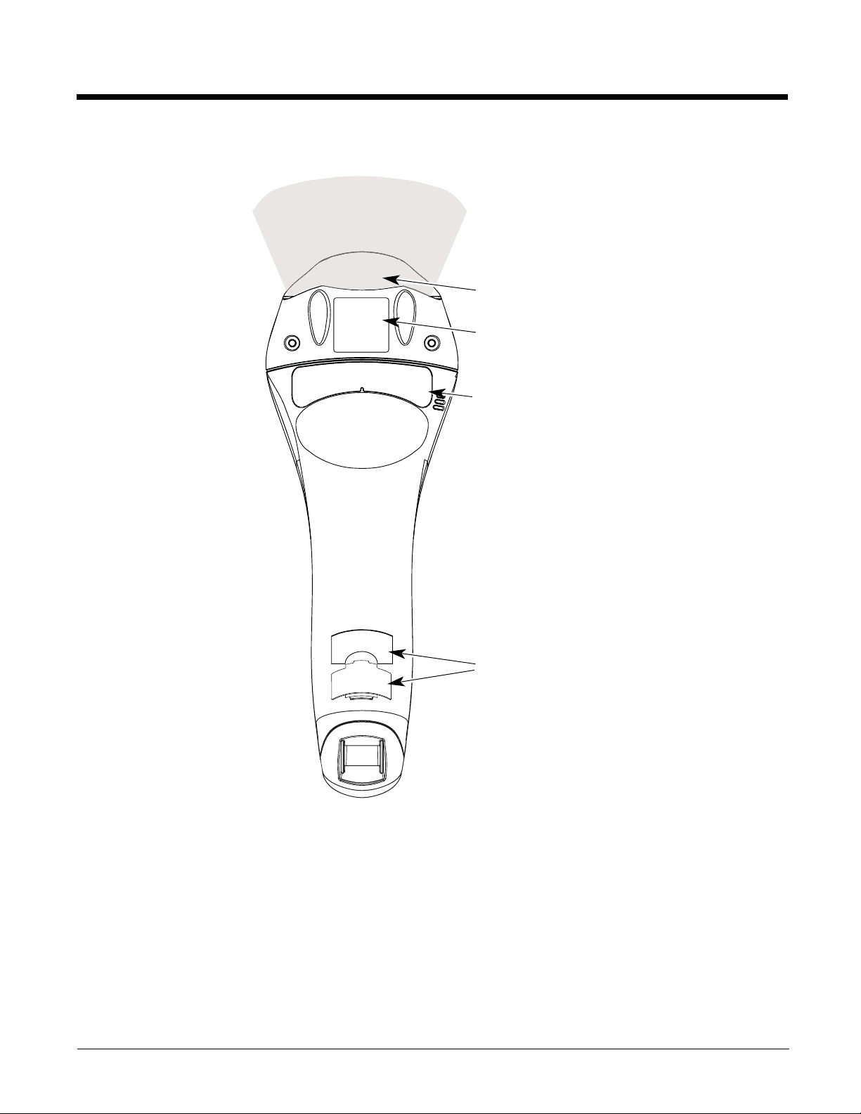
Voyager 1200g Safety Label Locations
Laser Output
Compliance Markings
information, Part Number,
and Serial Number
information
Compliance Markings
information
Internal Laser Cautions
Page 10
Voyager 1202g Safety Label Locations
Laser Output
Compliance Markings
information, Part Number,
and Serial Number
information
Compliance Markings
information
Internal Laser Cautions
Laser Safety Information
Page 11
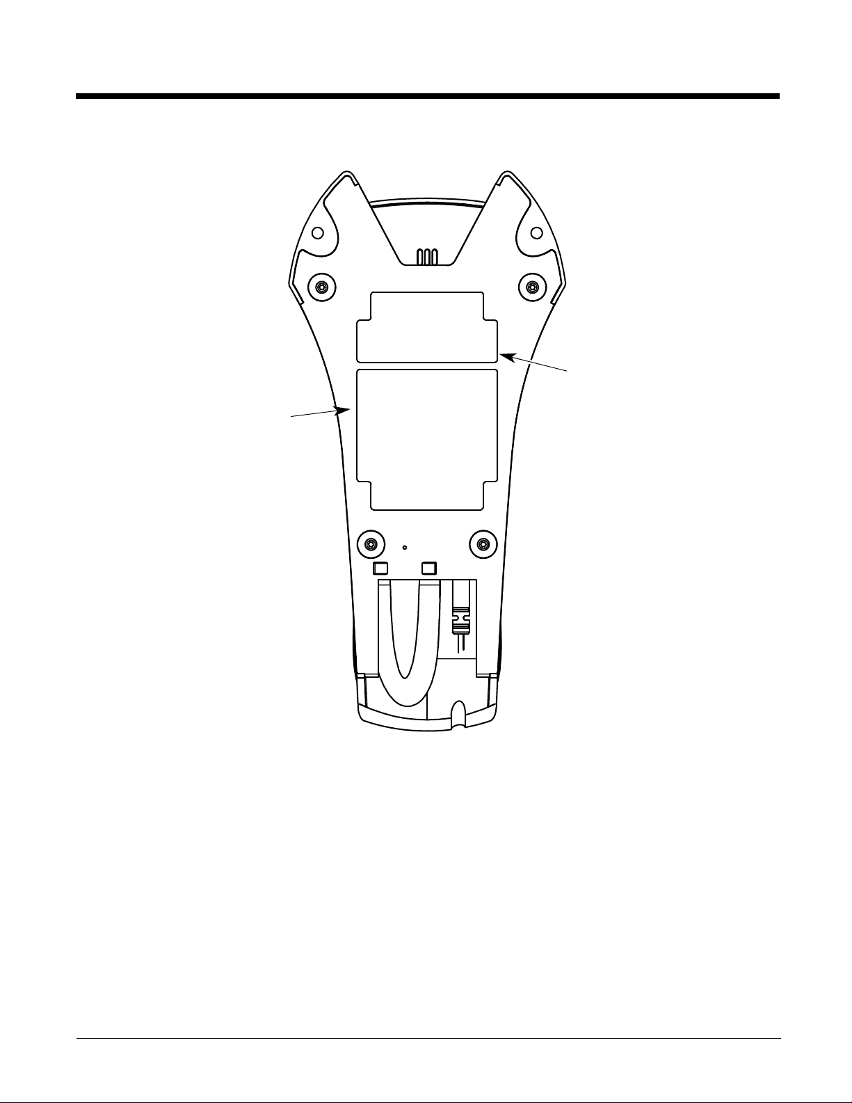
CCB00-010BT Safety Label Locations
Item Number,
Serial
Number, and
Compliance
Markings
information
Compliance
Markings
information
Page 12

Page 13

Table of Contents
Chapter 1 - Getting Started
About This Manual...............................................................................................................1-1
Unpacking Your Device .......................................................................................................1-1
Connecting the Device.........................................................................................................1-1
Connecting with USB .....................................................................................................1-1
Connecting with Keyboard Wedge.................................................................................1-2
Connecting with RS232 Serial Port................................................................................1-3
Connecting with RS485..................................................................................................1-4
Reading Techniques............................................................................................................1-5
Menu Bar Code Security Settings........................................................................................1-5
Setting Custom Defaults ......................................................................................................1-5
Resetting the Custom Defaults ............................................................................................1-6
Chapter 2 - Programming the Interface
Introduction ..........................................................................................................................2-1
Programming the Interface - Plug and Play.........................................................................2-1
Keyboard Wedge ...........................................................................................................2-1
IBM PS2 Keyboard.........................................................................................................2-1
RS232 Serial Port ..........................................................................................................2-1
RS485 ............................................................................................................................2-1
OPOS Mode...................................................................................................................2-2
USB IBM SurePos..........................................................................................................2-3
IBM Secondary Interface................................................................................................2-3
USB PC or Macintosh Keyboard....................................................................................2-4
USB HID.........................................................................................................................2-4
HID Fallback Mode.........................................................................................................2-4
USB Serial Commands ........................................................................................................2-4
USB Serial Emulation.....................................................................................................2-4
CTS/RTS Emulation.......................................................................................................2-5
ACK/NAK Mode .............................................................................................................2-5
Communication Timeout ................................................................................................2-5
NAK Retries ...................................................................................................................2-6
Support BEL/CAN in ACK/NAK......................................................................................2-6
Verifone
Gilbarco
Honeywell Bioptic Aux Port Configuration ...........................................................................2-7
Datalogic™ Magellan
NCR Bioptic Aux Port Configuration ....................................................................................2-8
Wincor Nixdorf Terminal Default Settings ............................................................................2-8
Wincor Nixdorf Beetle™ Terminal Default Settings .............................................................2-9
Wincor Nixdorf RS232 Mode A ............................................................................................2-9
Keyboard Country Layout ....................................................................................................2-9
®
Ruby Terminal Default Settings...........................................................................2-7
®
Terminal Default Settings ....................................................................................2-7
©
Bioptic Aux Port Configuration........................................................2-8
i
Page 14

Keyboard Wedge Modifiers ............................................................................................... 2-18
ALT Mode .................................................................................................................... 2-18
Keyboard Style ............................................................................................................2-18
Keyboard Conversion ..................................................................................................2-19
Keyboard Modifiers......................................................................................................2-19
Inter-Scan Code Delay ................................................................................................ 2-20
<F0> Break Character ................................................................................................. 2-21
Keyboard Wedge Defaults...........................................................................................2-21
RS232 Modifiers................................................................................................................2-22
RS232 Baud Rate........................................................................................................2-22
RS232 Word Length: Data Bits, Stop Bits, and Parity.................................................2-23
RS232 Handshaking....................................................................................................2-24
RS232 Timeout............................................................................................................2-25
XON/XOFF .................................................................................................................. 2-25
ACK/NAK ..................................................................................................................... 2-26
Communication Timeout.............................................................................................. 2-26
NAK Retries ................................................................................................................. 2-27
Support BEL/CAN in ACK/NAK ................................................................................... 2-27
RS232 Defaults............................................................................................................2-27
NCR Modifiers ...................................................................................................................2-27
NCR ACK/NAK ............................................................................................................2-27
Block Check Character ................................................................................................ 2-28
NCR Prefix................................................................................................................... 2-28
NCR Suffix...................................................................................................................2-28
NCR Prefix/Suffix.........................................................................................................2-28
NCR NOF (Not-on-File) Error ......................................................................................2-29
Scanner to Bioptic Communication ...................................................................................2-29
Scanner-Bioptic Packet Mode .....................................................................................2-29
ACK/NAK ..................................................................................................................... 2-29
Communication Timeout.............................................................................................. 2-30
Chapter 3 - Cordless System Operation
How the Charge and Communications Base Works ........................................................... 3-1
Linking the Scanner to a Base............................................................................................. 3-1
Communication Between the Cordless System
and the Host ......................................................................................................................3-1
RF (Radio Frequency) Module Operation ...........................................................................3-2
System Conditions...............................................................................................................3-2
Linking Process ............................................................................................................. 3-2
Scanner Is Out of Range...............................................................................................3-2
Scanner Is Moved Back Into Range ..............................................................................3-2
Out of Range and Back into Range with Batch Mode On..............................................3-2
Page Button.........................................................................................................................3-3
About the Battery................................................................................................................. 3-3
Voyager 1202g Battery Removal.........................................................................................3-3
Charging Information ..................................................................................................... 3-3
Battery Recommendations ............................................................................................3-4
Proper Disposal of the Battery.......................................................................................3-4
ii
Page 15

Flash Updates .....................................................................................................................3-4
Beeper and LED Sequences and Meaning .........................................................................3-4
Scanner LED Sequences and Meaning.........................................................................3-5
Base LED Sequences and Meaning..............................................................................3-5
Base Power Communication Indicator........................................................................... 3-5
Reset Scanner..................................................................................................................... 3-6
Scanning While in Base Cradle ........................................................................................... 3-6
Paging ................................................................................................................................. 3-6
Paging Mode.................................................................................................................. 3-6
Paging Pitch.................................................................................................................. 3-7
Error Indicators .................................................................................................................... 3-7
Scanner Address.................................................................................................................3-7
Base Address ...................................................................................................................... 3-7
Scanner Modes ...................................................................................................................3-7
Charge Only Mode......................................................................................................... 3-7
Linked Modes ................................................................................................................3-8
Unlinking the Scanner .........................................................................................................3-9
Override Locked Scanner .................................................................................................... 3-9
Out-of-Range Alarm ............................................................................................................ 3-9
Alarm Sound Type.........................................................................................................3-9
Alarm Duration............................................................................................................... 3-9
Scanner Power Time-Out Timer..........................................................................................3-9
RangeGate ........................................................................................................................ 3-10
Batch Mode ....................................................................................................................... 3-10
Batch Mode Beep ........................................................................................................ 3-11
Batch Mode Quantity ...................................................................................................3-11
Delete Last Code ......................................................................................................... 3-13
Record Counter ...........................................................................................................3-13
Total Records .............................................................................................................. 3-13
Batch Mode Output Order............................................................................................ 3-13
Clear All Codes After Transmission.............................................................................3-14
Clear All Codes............................................................................................................3-14
Transmit Records Automatically.................................................................................. 3-14
Transmit Records to Host ............................................................................................ 3-15
Batch Mode Transmit Delay ........................................................................................3-15
Scanner Name...................................................................................................................3-15
Using the Scanner with Bluetooth Devices........................................................................ 3-16
Changing the Scanner’s Bluetooth PIN Code.............................................................. 3-17
Minimizing Bluetooth/ISM Band Network Activity..............................................................3-17
Auto Reconnect Mode ................................................................................................. 3-17
Maximum Link Attempts .............................................................................................. 3-18
Relink Time-Out........................................................................................................... 3-18
Bluetooth/ISM Network Activity Examples................................................................... 3-18
Reset Scanner and Base...................................................................................................3-19
Chapter 4 - Input/Output Settings
Power Up Beeper ................................................................................................................4-1
Beep on BEL Character....................................................................................................... 4-1
iii
Page 16

Good Read and Error Indicators..........................................................................................4-1
Beeper – Good Read.....................................................................................................4-1
Beeper Volume – Good Read........................................................................................4-2
Beeper Pitch – Good Read............................................................................................4-2
Beeper - Transmit Order................................................................................................ 4-2
Beeper Pitch – Error ...................................................................................................... 4-3
Beeper Duration – Good Read ......................................................................................4-3
Number of Beeps – Good Read ....................................................................................4-3
Number of Beeps – Error............................................................................................... 4-3
LED Indicators ..................................................................................................................... 4-4
LED Settings.................................................................................................................. 4-4
LED Brightness.............................................................................................................. 4-5
In-Stand and Out-Of-Stand Settings....................................................................................4-6
In-Stand and Out-of-Stand Defaults ..............................................................................4-6
Presentation Modes.......................................................................................................4-6
Manual Activation Mode ................................................................................................4-7
End Manual Activation After Good Read.......................................................................4-7
Manual Activation Laser Timeout - Button Settings.......................................................4-8
CodeGate ......................................................................................................................4-9
Button Function.............................................................................................................. 4-9
Object Detection Mode .................................................................................................. 4-9
End Object Detection After Good Read.......................................................................4-10
Object Detection Laser Timeout..................................................................................4-11
Object Detection Distance ........................................................................................... 4-11
Character Activation Mode ................................................................................................ 4-11
Activation Character .................................................................................................... 4-12
End Character Activation After Good Read.................................................................4-12
Character Activation Laser Timeout ............................................................................4-12
Character Deactivation Mode ............................................................................................ 4-12
Deactivation Character ................................................................................................ 4-13
Reread Delay.....................................................................................................................4-13
User-Specified Reread Delay............................................................................................4-13
Output Sequence Overview...............................................................................................4-14
Output Sequence Editor ..............................................................................................4-14
To Add an Output Sequence .......................................................................................4-14
Other Programming Selections.................................................................................... 4-14
Output Sequence Editor ..............................................................................................4-16
Sequence Timeout.......................................................................................................4-16
Sequence Match Beeper .............................................................................................4-16
Partial Sequence .........................................................................................................4-16
Require Output Sequence...........................................................................................4-17
No Read ............................................................................................................................4-17
Chapter 5 - Data Editing
Prefix/Suffix Overview ......................................................................................................... 5-1
To Add a Prefix or Suffix:............................................................................................... 5-1
To Clear One or All Prefixes or Suffixes........................................................................ 5-2
To Add a Carriage Return Suffix to All Symbologies..................................................... 5-2
iv
Page 17

Prefix Selections.................................................................................................................. 5-2
Suffix Selections .................................................................................................................. 5-3
Transmit Alternate Extended ASCII Characters..................................................................5-3
Function Code Transmit ......................................................................................................5-4
Communication Check Character........................................................................................ 5-4
Intercharacter, Interfunction, and Intermessage Delays......................................................5-5
Intercharacter Delay ...................................................................................................... 5-5
User Specified Intercharacter Delay .............................................................................. 5-5
Interfunction Delay......................................................................................................... 5-6
Intermessage Delay....................................................................................................... 5-6
Chapter 6 - Data Formatting
Data Format Editor Introduction ..........................................................................................6-1
To Add a Data Format ......................................................................................................... 6-1
Other Programming Selections...................................................................................... 6-2
Terminal ID Table ................................................................................................................ 6-3
Data Format Editor Commands........................................................................................... 6-3
Move Commands........................................................................................................... 6-5
Search Commands........................................................................................................ 6-6
Miscellaneous Commands.............................................................................................6-8
Data Formatter ..................................................................................................................6-10
Data Format Non-Match Error Tone............................................................................ 6-11
Primary/Alternate Data Formats ........................................................................................ 6-11
Single Scan Data Format Change...............................................................................6-12
Chapter 7 - Symbologies
All Symbologies ................................................................................................................... 7-1
Message Length Description...............................................................................................7-1
Codabar............................................................................................................................... 7-2
Codabar Concatenation.................................................................................................7-3
Code 39 ............................................................................................................................... 7-5
Code 32 Pharmaceutical (PARAF)................................................................................7-6
Full ASCII....................................................................................................................... 7-7
Interleaved 2 of 5................................................................................................................. 7-8
NEC 2 of 5 ...........................................................................................................................7-9
Code 93 ............................................................................................................................. 7-11
Straight 2 of 5 Industrial (three-bar start/stop)................................................................... 7-12
Straight 2 of 5 IATA (two-bar start/stop) ............................................................................ 7-13
Matrix 2 of 5....................................................................................................................... 7-14
Code 11 ............................................................................................................................. 7-15
Code 128 ...........................................................................................................................7-17
ISBT 128 Concatenation..............................................................................................7-18
GS1-128 ............................................................................................................................7-23
Telepen.............................................................................................................................. 7-24
UPC-A ............................................................................................................................... 7-25
UPC-A/EAN-13 with Extended Coupon Code...................................................................7-28
UPC-A Number System 5 Addenda Required............................................................. 7-29
v
Page 18

UPC-E0 .............................................................................................................................7-30
EAN/JAN-13 ......................................................................................................................7-33
Convert UPC-A to EAN-13 .......................................................................................... 7-33
ISBN Translate ............................................................................................................ 7-39
ISSN Translate ............................................................................................................ 7-40
EAN/JAN-8 ........................................................................................................................ 7-41
MSI .................................................................................................................................... 7-43
Plessey Code ....................................................................................................................7-45
GS1 DataBar Omnidirectional ........................................................................................... 7-46
GS1 DataBar Limited......................................................................................................... 7-47
GS1 DataBar Expanded....................................................................................................7-48
Trioptic Code ..................................................................................................................... 7-48
GS1 Emulation .................................................................................................................. 7-49
Postal Codes ..................................................................................................................... 7-49
China Post (Hong Kong 2 of 5).................................................................................... 7-50
Chapter 8 - Interface Keys
Keyboard Function Relationships........................................................................................8-1
Supported Interface Keys .................................................................................................... 8-2
Chapter 9 - Utilities
To Add a Test Code I.D. Prefix to All Symbologies.............................................................9-1
Show Software Revision...................................................................................................... 9-1
Show Data Format............................................................................................................... 9-1
Test Menu............................................................................................................................ 9-1
EZConfig-Scanning Introduction..........................................................................................9-1
Installing EZConfig-Scanning from the Web..................................................................9-2
Resetting the Factory Defaults ............................................................................................ 9-3
Chapter 10 - Serial Programming Commands
Conventions.......................................................................................................................10-1
Menu Command Syntax ....................................................................................................10-1
Query Commands .............................................................................................................10-1
Responses...................................................................................................................10-2
Serial Trigger Commands..................................................................................................10-3
Read Time-Out ............................................................................................................10-3
Resetting the Standard Product Defaults ..........................................................................10-3
Menu Commands ..............................................................................................................10-4
Chapter 11 - Product Specifications
Voyager 1200g Product Specifications..............................................................................11-1
Voyager 1202g Product Specifications..............................................................................11-2
CCB00-010BT Product Specifications...............................................................................11-3
CCB00-010BT Mounting ...................................................................................................11-4
vi
Page 19

Standard Cable Pinouts.....................................................................................................11-5
Keyboard Wedge.........................................................................................................11-5
Serial Output ............................................................................................................... 11-5
RS485 Output .............................................................................................................11-6
USB ............................................................................................................................. 11-6
Chapter 12 - Maintenance
Repairs .............................................................................................................................. 12-1
Maintenance......................................................................................................................12-1
Cleaning the Device.....................................................................................................12-1
Inspecting Cords and Connectors ...............................................................................12-1
Replacing Cables in Corded Scanners.............................................................................. 12-1
Replacing an Interface Cable in a Corded Scanner ....................................................12-2
Replacing Cables in Cordless Systems............................................................................. 12-2
Replacing an Interface Cable in a Base ...................................................................... 12-2
Troubleshooting a Voyager Scanner.................................................................................12-3
Troubleshooting a Cordless System..................................................................................12-4
Troubleshooting a Base...............................................................................................12-4
Troubleshooting a Cordless Scanner .......................................................................... 12-4
Chapter 13 - Customer Support
Technical Assistance......................................................................................................... 13-1
Product Service and Repair...............................................................................................13-1
Limited Warranty ............................................................................................................... 13-1
Appendix A - Reference Charts
Symbology Charts ...............................................................................................................A-1
Linear Symbologies .......................................................................................................A-1
Postal Symbologies .......................................................................................................A-2
ASCII Conversion Chart (Code Page 1252)........................................................................A-2
Lower ASCII Reference Table.............................................................................................A-3
ISO 2022/ISO 646 Character Replacements ......................................................................A-7
Unicode Key Maps ..............................................................................................................A-9
Sample Symbols
Programming Chart
vii
Page 20

viii
Page 21
1
Charge and
Communications
Base USB
Connection:
Getting Started
About This Manual
This User’s Guide provides installation and programming instructions for the Voyager 1200g/1202g linear scanner. Product
specifications, dimensions, warranty, and customer support information are also included.
Honeywell bar code scanners are factory programmed for the most common terminal and communications settings. If you need
to change these settings, programming is accomplished by scanning the bar codes in this guide.
An asterisk (*) next to an option indicates the default setting.
Unpacking Your Device
After you open the shipping carton containing the product, take the following steps:
• Check for damage during shipment. Report damage immediately to the carrier who delivered the carton.
• Make sure the items in the carton match your order.
• Save the shipping container for later storage or shipping.
Connecting the Device
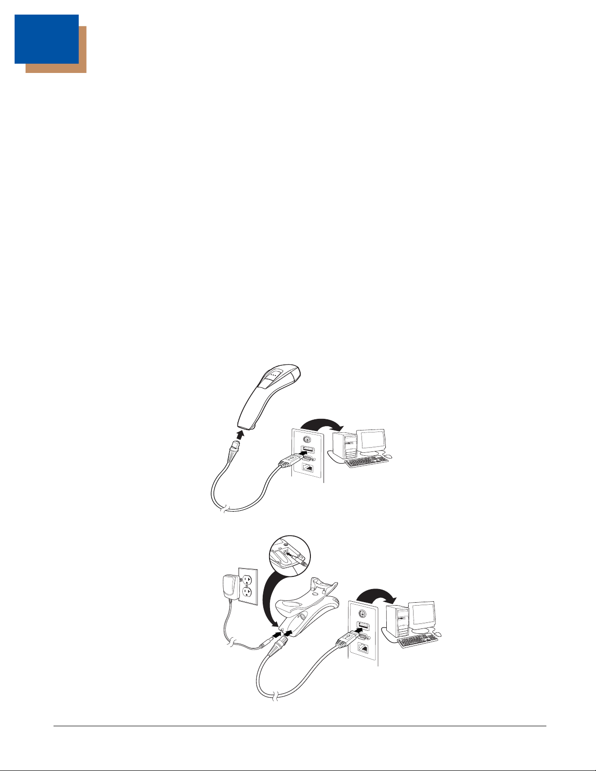
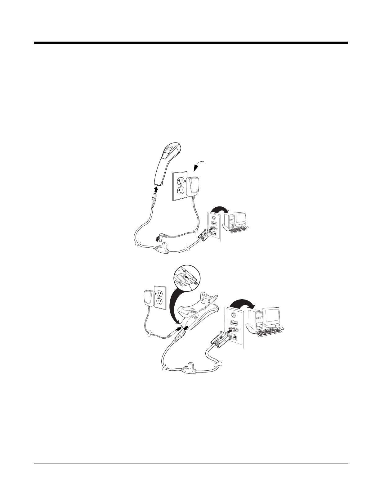
Connecting with USB
A scanner or a base can be connected to the USB port of a computer.
1. Connect the appropriate interface cable to the scanner first, then to the computer.
1 - 1
Page 22

2. Make sure the cables are secured in the wireways in the bottom of the base and that the base sits flat on a horizontal
only if
power
supply is
included
Charge and
Communications Base
Keyboard Wedge
Connection:
surface.
3. The scanner beeps.
4. Verify the scanner or base operation by scanning a bar code from the Sample Symbols in the back of this manual.
The unit defaults to a USB PC Keyboard. Refer to page 2-4 for other USB terminal settings.
For additional USB programming and technical information, refer to “USB Application Note,” available at www.honey-
wellaidc.com.
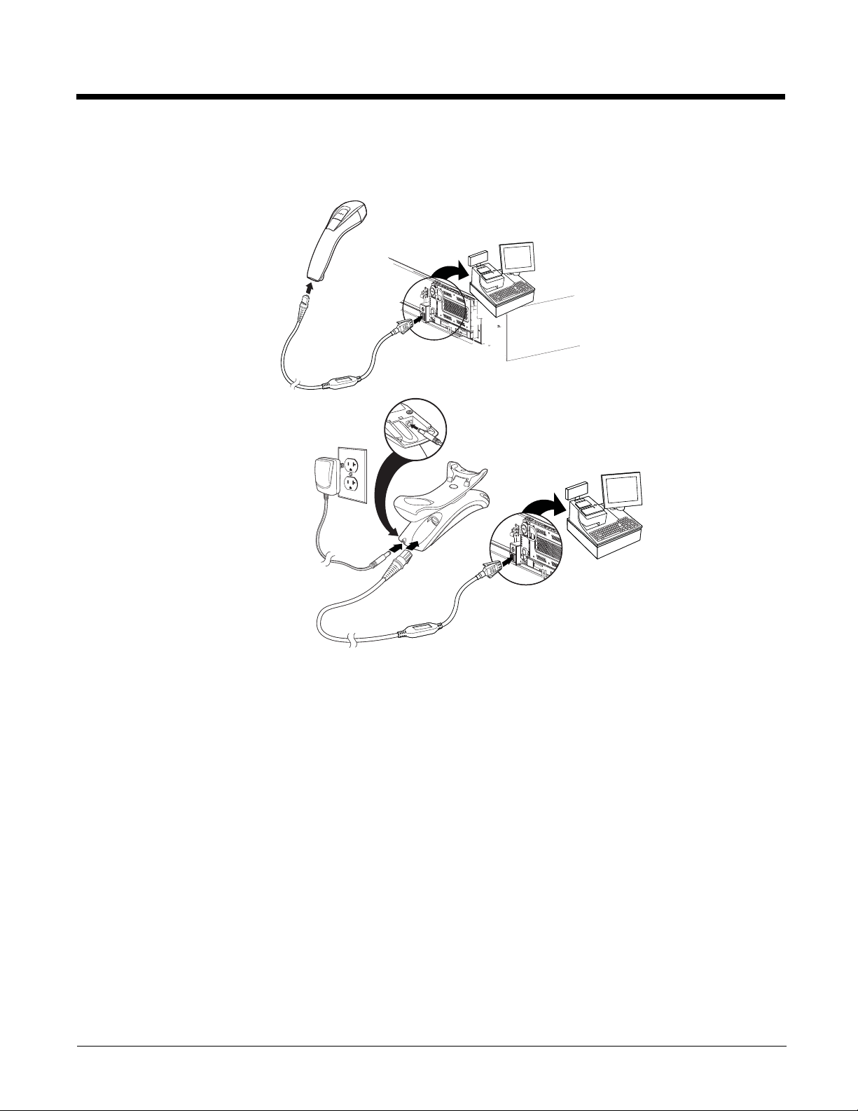
Connecting with Keyboard Wedge
A scanner or base can be connected between the keyboard and PC as a “keyboard wedge,” where the scanner provides
data output that is similar to keyboard entries. The following is an example of a keyboard wedge connection:
1. Turn off power and disconnect the keyboard cable from the back of the terminal/computer.
2. Connect the appropriate interface cable to the scanner and to the terminal/computer.
3. Make sure the cables are secured in the wireways in the bottom of the base and that the base sits flat on a horizontal
surface.
4. Turn the terminal/computer power back on. The scanner beeps.
1 - 2
Page 23
5. Verify the scanner or base operation by scanning a bar code from the Sample Symbols in the back of this manual. The
only if
power
supply is
included
Charge and
Communications
Base RS232
Serial Port
Connection:
scanner beeps once.
The unit defaults to an IBM PC AT and compatibles keyboard wedge interface with a USA keyboard. A carriage return (CR)
suffix is added to bar code data.
Connecting with RS232 Serial Port
1. Turn off power to the terminal/computer.
2. Connect the appropriate interface cable to the scanner.
Note: For the scanner or base to work properly, you must have the correct cable for your type of terminal/computer.
3. Make sure the cables are secured in the wireways in the bottom of the base and that the base sits flat on a horizontal
surface.
4. Plug the serial connector into the serial port on your computer. Tighten the two screws to secure the connector to the
port.
5. Once the scanner or base has been fully connected, power up the computer.
This interface programs 9600 baud, 8 data bits, no parity, and 1 stop bit.
1 - 3
Page 24
Connecting with RS485
Charge and
Communications
Base RS485
Connection:
A scanner or base can be connected for an IBM POS terminal interface.
1. Connect the appropriate interface cable to the device, then to the computer.
2. Make sure the cables are secured in the wireways in the bottom of the base and that the base sits flat on a horizontal
surface.
3. Turn the terminal/computer power back on. The scanner beeps.
4. Verify the scanner or base operation by scanning a bar code from the Sample Symbols in the back of this manual. The
scanner beeps once.
For further RS485 settings, refer to RS485, page 2-1.
1 - 4
Page 25

Reading Techniques
Good Read Bad Read
Set Custom Defaults
Save Custom Defaults
The scanner has a view finder that projects a bright red aiming beam that corresponds to the scanner’s horizontal field of view.
The aiming beam should be centered horizontally over the bar code and must highlight all the vertical bars of the bar code. It
will not read if the aiming beam is in any other direction.
The aiming beam is smaller when the scanner is closer to the code and larger when it is farther from the code. Symbologies
with smaller bars or elements (mil size) should be read closer to the unit. Symbologies with larger bars or elements (mil size)
should be read farther from the unit. To read single or multiple symbols (on a page or on an object), hold the scanner at an
appropriate distance from the target, press the button, and center the aiming beam on the symbol. If the code being scanned is
highly reflective (e.g., laminated), it may be necessary to tilt the code up 15° to 18° to prevent unwanted reflection.
Menu Bar Code Security Settings
Honeywell scanners are programmed by scanning menu bar codes or by sending serial commands to the scanner. If you want
to restrict the ability to scan menu codes, you can use the Menu Bar Code Security settings. Please contact the nearest technical support office (see Limited Warranty on page 13-1) for further information.
Setting Custom Defaults
You have the ability to create a set of menu commands as your own, custom defaults. To do so, scan the Set Custom Defaults
bar code below before each menu command or sequence you want saved. If your command requires scanning numeric codes
from the back cover, then a Save code, that entire sequence will be saved to your custom defaults. Scan the Set Custom
Defaults code again before the next command you want saved to your custom defaults.
When you have entered all the commands you want to save for your custom defaults, scan the Save Custom Defaults bar
code.
Note: If using a cordless system, scanning the Save Defaults bar code also causes both the scanner and the base to perform
a reset and become unlinked. The scanner must be placed in its base to re-establish the link before any setup codes are
entered. See Cordless System Operation beginning on page 3-1 for additional information.
You may have a series of custom settings and want to correct a single setting. To do so, just scan the new setting to overwrite
the old one. For example, if you had previously saved the setting for Beeper Volume at Low to your custom defaults, and decide
you want the beeper volume set to High, just scan the Set Custom Defaults bar code, then scan the Beeper Volume High
menu code, and then Save Custom Defaults. The rest of the custom defaults will remain, but the beeper volume setting will be
updated.
1 - 5
Page 26

Resetting the Custom Defaults
Activate Custom Defaults
If you want the custom default settings restored to your scanner, scan the Activate Custom Defaults bar code below. This
resets the scanner to the custom default settings. If there are no custom defaults, it will reset the scanner to the factory default
settings. Any settings that have not been specified through the custom defaults will be defaulted to the factory default settings.
Note: If using a cordless system, scanning this bar code also causes both the scanner and the base to perform a reset and
become unlinked. The scanner must be placed in its base to re-establish the link before any setup codes are entered.
See Cordless System Operation beginning on page 3-1 for additional information.
1 - 6
Page 27

2
IBM PC AT and Compatibles with CR Suffix
IBM PS2 with CR Suffix
RS232 Interface
IBM Port 5B Interface
Programming the Interface
Introduction
This chapter describes how to program your system for the desired interface.
Programming the Interface - Plug and Play
Plug and Play bar codes provide instant scanner set up for commonly used interfaces.
Note: After you scan one of the codes, power cycle the host terminal to have the interface in effect.
Keyboard Wedge
If you want your system programmed for an IBM PC AT and compatibles keyboard wedge interface with a USA keyboard,
scan the bar code below. Keyboard wedge is the default interface.
Note: The following bar code also programs a carriage return (CR) suffix.
IBM PS2 Keyboard
The following bar code programs you scanner for an IBM PS2 keyboard wedge interface with a USA keyboard.
Note: The following bar code also programs a carriage return (CR) suffix.
RS232 Serial Port
The RS232 Interface bar code is used when connecting to the serial port of a PC or terminal. The following RS232 Interface bar code also programs a carriage return (CR) and a line feed (LF) suffix, baud rate, and data format as indicated
below.
Option Setting
Baud Rate 115,200 bps
Data Format 8 data bits, no parity bit, 1 stop bit
RS485
Scan one of the following “Plug and Play” codes to program the scanner for an IBM POS terminal interface.
Note: After scanning one of these codes, you must power cycle the cash register.
2 - 1
Page 28
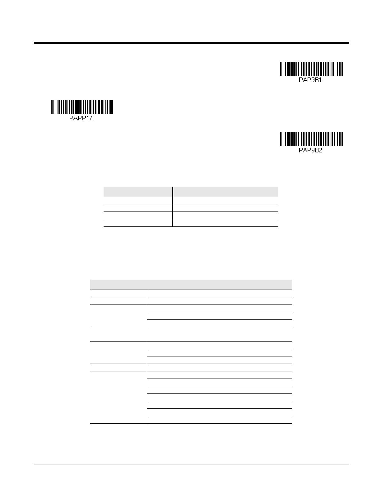
Each bar code above also programs the following suffixes for each symbology:
IBM Port 9B
HHBCR-1 Interface
IBM Port 17 Interface
IBM Port 9B
HHBCR-2 Interface
Symbology Suffix Symbology Suffix
EAN 8 0C Code 39 00 0A 0B
EAN 13 16 Interleaved 2 of 5 00 0D 0B
UPC A 0D Code 128 * 00 0A 0B
UPC E 0A Code 128 ** 00 18 0B
* Suffixes programmed for Code 128 with IBM 4683 Port 5B, IBM 4683 Port 9B HHBCR-1, and IBM 4683 Port 17 Interfaces
**Suffixes programmed for Code 128 with IBM 4683 Port 9 HHBCR-2 Interface
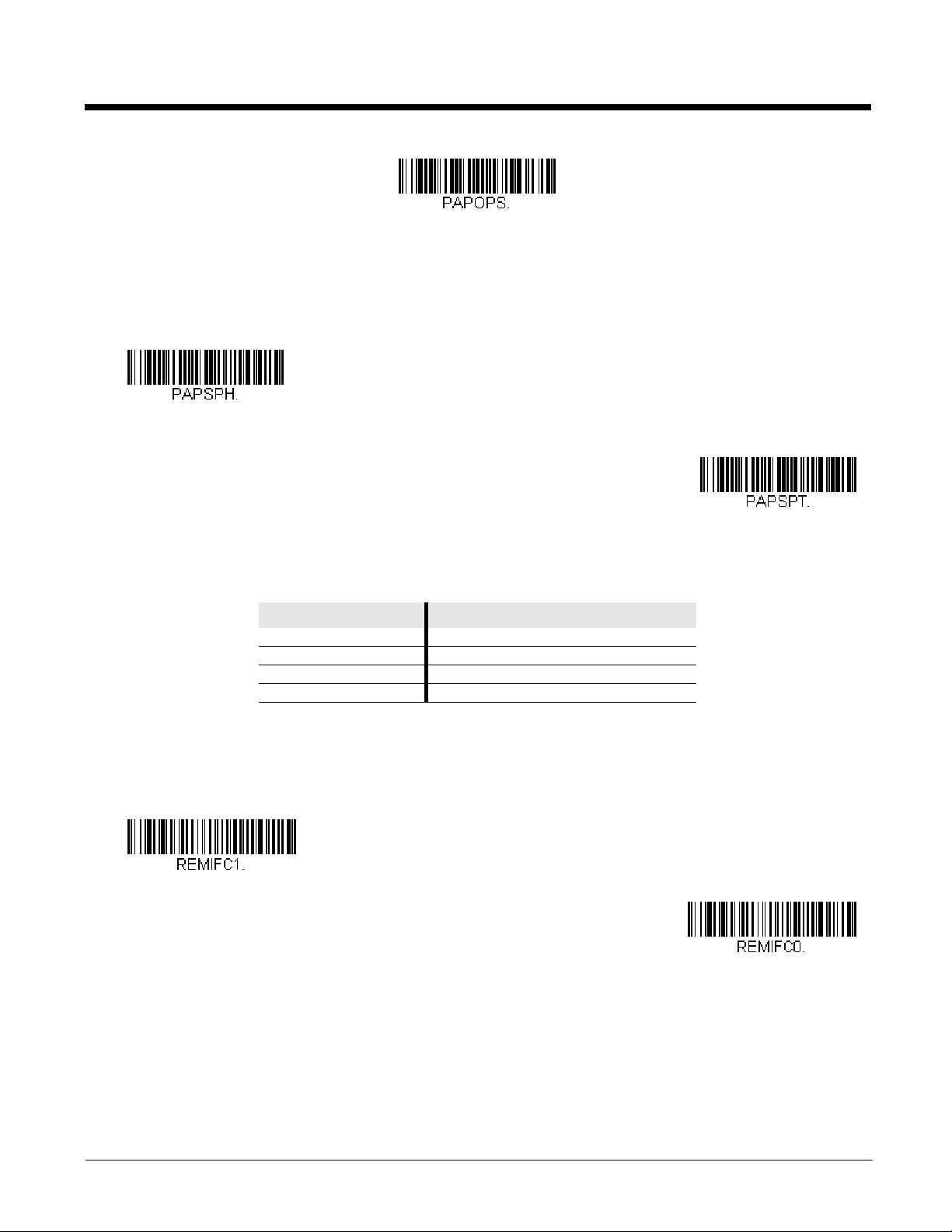
OPOS Mode
The following bar code configures your scanner for OPOS (OLE for Retail Point of Sale) by modifying the following OPOSrelated settings:
Option Setting
Interface RS232
Baud Rate 38400
RS232 Handshaking Flow Control, No Timeout
XON/XOFF Off
ACK/NAK Off
Data Bits, Stop Bits,
and Parity
Prefix/Suffix
Intercharacter Delay Off
Symbologies Enable UPC-A with check digit and number system
8 Data, 1 Stop, Parity None
Clear All Prefixes and Suffixes
Add Code ID and AIM ID Prefix
Add CR Suffix
Enable UPC-E0 with check digit
Enable EAN/JAN-8 with check digit
Enable EAN/JAN-13 with check digit
Enable Code 128
Enable Code 39
Enable OPOS with automatic disable off
2 - 2
Page 29
USB IBM SurePos
OPOS Mode
USB IBM SurePos
(USB Handheld Scanner)
Interface
USB IBM SurePos
(USB Tabletop Scanner)
Interface
*Enable Secondary Interface
Disable Secondary Interface
Scan one of the following “Plug and Play” codes to program the scanner for an IBM SurePos (USB handheld scanner) or
IBM SurePos (USB tabletop scanner) interface.
Note: After scanning one of these codes, you must power cycle the cash register.
Each bar code above also programs the following suffixes for each symbology:
Symbology Suffix Symbology Suffix
EAN 8 0C Code 39 00 0A 0B
EAN 13 16 Interleaved 2 of 5 00 0D 0B
UPC A 0D Code 128 00 18 0B
UPC E 0A Code 39 00 0A 0B
IBM Secondary Interface
On some older IBM cash registers, it may be necessary to disable the secondary or management interface. In particular, it
has been found necessary on IBM registers using the 4690 V2R4 operating system. The following bar codes are used for
this purpose. Default = Enable Secondary Interface.
2 - 3
Page 30
USB PC or Macintosh Keyboard
U
S
B
K
e
y
b
o
a
r
d
(
P
C
)
USB Keyboard (Mac)
USB Japanese Keyboard (PC)
USB HID Bar Code Scanner
HID Fallback Mode
Scan one of the following codes to program the scanner for USB PC Keyboard or USB Macintosh Keyboard. Scanning
these codes also adds a CR and LF.
USB HID
Scan the following code to program the scanner for USB HID bar code scanners.
HID Fallback Mode
If you attempt to set a USB interface for your scanner, but the setup fails on the host system, you can program the scanner
to fall back to a HID keyboard interface after a set length of time. For example, if the scanner is configured for Serial Emulation Mode, but the host system does not have the correct driver, the scanner would fail. If you set the HID Fallback Mode
for a set length of time, for example, 5 minutes, the scanner would change to a HID keyboard interface after 5 minutes of
trying to configure as serial emulation.
A unique beep sequence indicates that this mode has been entered. While in HID Fallback Mode, the scanner will not scan
normal bar codes and sounds a unique beep sequence that indicates the scanner is in Fallback Mode. Menu codes can
still be scanned while in HID Fallback Mode, allowing you to change the scanner’s programming.
Scan the bar code below, then set the length for the HID Fallback (from 0-60 minutes) by scanning digits from the
Programming Chart, then scanning Save. Default = 5 minutes.
USB Serial Commands
USB Serial Emulation
Scan one of the following codes to program the scanner to emulate a regular RS232-based COM Port. If you are using a
Microsoft® Windows® PC, you will need to download a driver from the Honeywell website (www.honeywellaidc.com). The
driver will use the next available COM Port number. Apple® Macintosh computers recognize the scanner as a USB CDC
class device and automatically uses a class driver.
2 - 4
Page 31

Scanning either of these codes also adds a CR and LF.
USB Serial Emulation for
Windows XP, Windows Server
2003, and later
USB Serial Emulation for Windows 2000
CTS/RTS Emulation On
* CTS/RTS Emulation Off
ACK/NAK Mode On
* ACK/NAK Mode Off
Communication Timeout
Note: No extra configuration (e.g., baud rate) is necessary.
CTS/RTS Emulation
ACK/NAK Mode
Communication Timeout
This allows you to set the length (in milliseconds) for a timeout for the host ACK/NAK response. Scan the bar code below,
then set the timeout (from 0-65535 milliseconds) by scanning digits from the Programming Chart, then scanning Save.
Default = 2000 ms.
2 - 5
Page 32

Timeout Retries
Timeout Retries
O
f
f
* On
NAK Retries
BEL/CAN On
* BEL/CAN Off
This setting limits the number of Communication Timeout retries. If the Timeout Retries is set to 0, the transmission is
terminated after the initial Communication Timeout. Scan the bar code below, then set the number of retries (from 0-
255) by scanning digits from the Programming Chart, then scanning Save. (5 is the recommended setting.) Default =
0.
Communication Timeout Beeper
This selection programs the scanner to issue an error beep when a communication timeout has occurred. The error
beep sound is programmed using Number of Beeps – Error (page 4-3). Default = On.
NAK Retries
This selection limits the number of NAK retries that can occur in ACK/NAK mode. Scan the bar code below, then set the
number of retries (from 0-255) by scanning digits from the Programming Chart, then scanning Save. (5 is the recommended setting.) Default = 0, or disabled.
Support BEL/CAN in ACK/NAK
This protocol responds to <BEL> and <CAN> commands when in ACK/NAK mode. The scanner sounds an error tone
when a <BEL> command is sent from the host. <CAN> terminates the transmission. Default = BEL/CAN Off.
2 - 6
Page 33

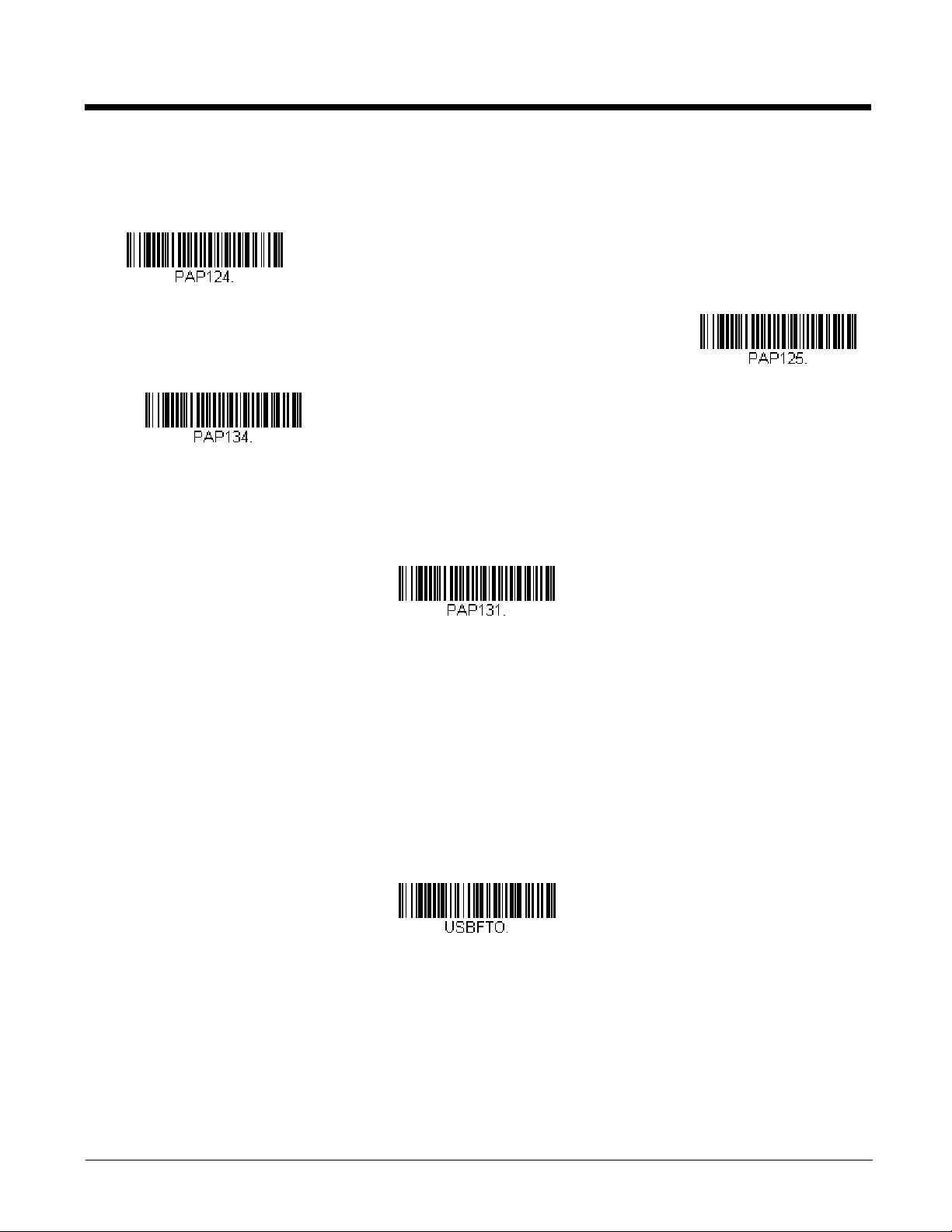
Verifone® Ruby Terminal Default Settings
Verifone Ruby Settings
Gilbarco Settings
Honeywell Bioptic Settings
Scan the following Plug and Play code to program the scanner for a Verifone Ruby terminal. This bar code sets the baud rate to
1200 bps and the data format to 8 data bits, Mark parity, 1 stop bit and RTS/CTS no timeout. It also adds a line feed (LF) suffix
and programs the following prefixes for each symbology:
Symbology Prefix
UPC-A A
UPC-E A
EAN-8 FF
EAN-13 F
Note: If you are having unexpected results with this programming code, scan the Resetting the Custom Defaults bar code on
page 1-6 first, then scan the programming code above.
Gilbarco® Terminal Default Settings
Scan the following Plug and Play code to program the scanner for a Gilbarco terminal. This bar code sets the baud rate to 2400
bps and the data format to 7 data bits, even parity, 2 stop bits. It also adds a carriage return (CR) suffix and programs the following prefixes for each symbology:
Symbology Prefix
UPC-A A
UPC-E E0
EAN-8 FF
EAN-13 F
Note: If you are having unexpected results with this programming code, scan the Resetting the Custom Defaults bar code on
page 1-6 first, then scan the programming code above.
Honeywell Bioptic Aux Port Configuration
Scan the following Plug and Play code to program the scanner for a Honeywell bioptic scanner auxiliary port configuration. This
bar code sets the baud rate to 38400 bps and the data format to 8 data bits, no parity, 1 stop bit. Character RTS/CTS with timeout and 232 ACK/NAK are also enabled.
Note: If you are having unexpected results with this programming code, scan the Resetting the Custom Defaults bar code on
page 1-6 first, then scan the programming code above.
2 - 7
Page 34

Datalogic™ Magellan©Bioptic Aux Port Configuration
Datalogic Magellan Bioptic Settings
NCR Bioptic Settings
Wincor Nixdorf Terminal Settings
Scan the following Plug and Play code to program the scanner for a Datalogic Magellan bioptic scanner auxiliary port configuration. This bar code sets the baud rate to 9600 bps and the data format to 8 data bits, no parity, 1 stop bit.
Note: If you are having unexpected results with this programming code, scan the Resetting the Custom Defaults bar code on
page 1-6 first, then scan the programming code above.
NCR Bioptic Aux Port Configuration
Scan the following Plug and Play code to program the scanner for an NCR bioptic scanner auxiliary port configuration. This bar
code sets the baud rate to 9600 bps and the data format to 7 data bits, Even parity, 1 stop bit and Message RTS/CTS with timeout. The following prefixes are programmed for each symbology:
Symbology Prefix Symbology Prefix
UPC-A A Code 39 B1
UPC-E E0 Interleaved 2 of 5 B2
EAN-8 FF All other bar
codes
EAN-13 F
B3
Note: If you are having unexpected results with this programming code, scan the Resetting the Custom Defaults bar code on
page 1-6 first, then scan the programming code above.
Wincor Nixdorf Terminal Default Settings
Scan the following Plug and Play code to program the scanner for a Wincor Nixdorf terminal. This bar code sets the baud rate
to 9600 bps and the data format to 8 data bits, no parity, 1 stop bit.
Note: If you are having unexpected results with this programming code, scan the Resetting the Custom Defaults bar code on
page 1-6 first, then scan the programming code above.
2 - 8
Page 35

Wincor Nixdorf Beetle™ Terminal Default Settings
Wincor Nixdorf Beetle Settings
Wincor Nixdorf RS232 Mode A
Settings
* United States
Scan the following Plug and Play code to program the scanner for a Wincor Nixdorf Beetle terminal. The following prefixes are
programmed for each symbology:
Symbology Prefix Symbology Prefix
Code 128 K EAN-13 A
Code 93 L GS1-128 P
Codabar N Interleaved 2 of 5 I
UPC-A A0 Plessey O
UPC-E C Straight 2 of 5 IATA H
EAN-8 B All other bar codes M
Note: If you are having unexpected results with this programming code, scan the Resetting the Custom Defaults bar code on
page 1-6 first, then scan the programming code above.
Wincor Nixdorf RS232 Mode A
Scan the following Plug and Play code to program the scanner for a Wincor Nixdorf RS232 Mode A terminal. The following prefixes are programmed for each symbology:
Symbology Prefix Symbology Prefix
Code 128 K EAN-13 A
Code 93 L GS1-128 K
Codabar N Interleaved 2 of 5 I
UPC-A A0 Plessey O
UPC-E C Straight 2 of 5 IATA H
EAN-8 B GS1 DataBar E
All other bar codes M
Keyboard Country Layout
Scan the appropriate country code below to program the keyboard layout for your country or language. As a general rule, the
following characters are supported, but need special care for countries other than the United States:
@ | $ # { } [ ] = / ‘ \ < > ~
Keyboard Countries
2 - 9
Page 36

Keyboard Countries (Continued)
Albania
Arabic
Azeri (Cyrillic)
Azeri (Latin)
Belarus
Belgium
Bosnia
Brazil
Brazil (MS)
Bulgaria (Cyrillic)
Bulgaria (Latin)
2 - 10
Page 37

Keyboard Countries (Continued)
Canada (French legacy)
Canada (French)
Canada (Multilingual)
China
Croatia
Czech
Czech (Programmers)
Czech (QWERTY)
Czech (QWERTZ)
Denmark
Dutch (Netherlands)
2 - 11
Page 38

Keyboard Countries (Continued)
Estonia
Faroese
Finland
France
Gaelic
Germany
Greek
Greek (220 Latin)
Greek (220)
Greek (319 Latin)
Greek (319)
2 - 12
Page 39

Keyboard Countries (Continued)
Greek (Latin)
Greek (MS)
Greek (Polytonic)
Hebrew
Hungarian (101 key)
Hungary
Iceland
Irish
Italian (142)
Italy
Japan ASCII
2 - 13
Page 40

Keyboard Countries (Continued)
Korea
Kazakh
Kyrgyz (Cyrillic)
Latin America
Latvia
Latvia (QWERTY)
Lithuania
Lithuania (IBM)
Macedonia
Malta
Mongolian (Cyrillic)
2 - 14
Page 41

Keyboard Countries (Continued)
Norway
Poland
Polish (214)
Polish (Programmers)
Portugal
Romania
Russia
Russian (MS)
Russian (Typewriter)
SCS
Serbia (Cyrillic)
2 - 15
Page 42

Keyboard Countries (Continued)
Serbia (Latin)
Slovakia
Slovakia (QWERTY)
Slovakia (QWERTZ)
Slovenia
Spain
Spanish variation
Sweden
Switzerland (French)
Switzerland (German)
Tatar
2 - 16
Page 43

Keyboard Countries (Continued)
Thailand
Turkey F
Turkey Q
Ukrainian
United Kingdom
United States (Dvorak)
United States (Dvorak left)
United Stated (Dvorak right)
United States (International)
Uzbek (Cyrillic)
Vietnam
2 - 17
Page 44

Keyboard Wedge Modifiers
* Off
3 Characters
4 Characters
* Regular
Caps Lock
Shift Lock
ALT Mode
If your bar code contains special characters from the extended ASCII chart for example, an e with an accent grave (è), you
will use ALT Mode. (See "Extended ASCII Characters" on page A-4.)
Note: Scan the ALT mode bar code after scanning the appropriate Keyboard Country code.
If your keystrokes require using the ALT key and 3 characters, scan the 3 Characters bar code. If your keystrokes require
the ALT key and 4 characters, scan the 4 Characters bar code. The data is then output with the special character(s).
Default = Off.
Keyboard Style
This programs keyboard styles, such as Caps Lock and Shift Lock. If you have used Keyboard Conversion settings, they
will override any of the following Keyboard Style settings. Default = Regular.
Regular is used when you normally have the Caps Lock key off.
Caps Lock is used when you normally have the Caps Lock key on.
Shift Lock is used when you normally have the Shift Lock key on (not common to U.S. keyboards).
2 - 18
Page 45

Autocaps via NumLock bar code should be scanned in countries (e.g., Germany, France) where the Caps Lock key can-
Autocaps via NumLock
Emulate External Keyboard
* Keyboard Conversion Off
Convert All Characters to Upper
Case
Convert All Characters to Lower
Case
not be used to toggle Caps Lock. The NumLock option works similarly to the regular Autocaps, but uses the NumLock key
to retrieve the current state of the Caps Lock.
Emulate External Keyboard should be scanned if you do not have an external keyboard (IBM AT or equivalent).
Note: After scanning the Emulate External Keyboard bar code, you must power cycle your computer.
Keyboard Conversion
Alphabetic keyboard characters can be forced to be all upper case or all lowercase. So if you have the following bar code:
“abc569GK,” you can make the output “ABC569GK” by scanning Convert All Characters to Upper Case, or to “abc569gk”
by scanning Convert All Characters to Lower Case. These settings override Keyboard Style selections.
Default = Keyboard Conversion Off.
Keyboard Modifiers
This modifies special keyboard features, such as CTRL+ ASCII codes and Turbo Mode.
Control + ASCII Mode On: The scanner sends key combinations for ASCII control characters for values 00-1F (refer to the
ASCII Conversion Chart (Code Page 1252), page A-2). Windows is the preferred mode. All keyboard country codes are
supported. DOS mode is a legacy mode, and it does not support all keyboard country codes. New users should use the
Windows mode.
Windows Mode Prefix/Suffix Off: The scanner sends key combinations for ASCII control characters for values 00-1F
(refer to the ASCII Conversion Chart (Code Page 1252), page A-2), but it does not transmit any prefix or suffix information.
2 - 19
Page 46

Default = Control + ASCII Mode Off.
Windows Mode Control + ASCII
Mode On
* Control + ASCII Mode Off
DOS Mode Control + ASCII Mode
On
Windows Mode Prefix/Suffix Off
Numeric Keypad Mode On
* Numeric Keypad Mode Off
Inter-Scan Code Delay
Numeric Keypad Mode: Sends numeric characters as if entered from a numeric keypad. Default = Off.
Inter-Scan Code Delay
When your keyboard detects that any key is being pressed, released, or held down, the keyboard sends a packet of information known as a “scan code” to your computer. This selection allows you to adjust the delay between scan codes. Set
the length (in milliseconds) for a delay by scanning the bar code below, then setting the delay (from 1-30) by scanning digits
from the Programming Chart, then scanning Save. Default = 0 (800 µs).
2 - 20
Page 47

<F0> Break Character
Suppress
* Transmit
Keyboard Wedge Defaults
When your keyboard detects that any key is being pressed, released, or held down, the keyboard sends a packet of information known as a “scan code” to your computer. There are two different types of scan codes: “make codes” and “break
codes.” A make code is sent when a key is pressed or held down. A break code is sent when a key is released. The fol-
lowing selections allow you to suppress or transmit the character sequence of the break code. Default = Transmit.
Keyboard Wedge Defaults
If you want the custom keyboard wedge default settings restored to your scanner, scan the Keyboard Wedge Defaults bar
code below. This resets the scanner to the custom default settings (see Setting Custom Defaults on page 1-5). If there are
no custom defaults, it will reset the scanner to the factory default settings. Any settings that have not been specified
through the custom defaults will be defaulted to the factory default settings.
2 - 21
Page 48

RS232 Modifiers
300
600
1200
2400
4800
* 9600
19200
38400
57,600
115,200
RS232 Baud Rate
Baud Rate sends the data from the scanner to the terminal at the specified rate. The host terminal must be set for the
same baud rate as the scanner. Default = 9600.
2 - 22
Page 49

RS232 Word Length: Data Bits, Stop Bits, and Parity
7 Data, 1 Stop, Parity Even
7 Data, 1 Stop, Parity None
7 Data, 1 Stop, Parity Odd
7 Data, 2 Stop, Parity Even
7 Data, 2 Stop Parity None
7 Data, 2 Stop, Parity Odd
8 Data, 1 Stop, Parity Even
* 8 Data, 1 Stop, Parity None
8 Data, 1 Stop, Parity Odd
7 Data, 1 Stop, Parity Space
Data Bits sets the word length at 7 or 8 bits of data per character. If an application requires only ASCII Hex characters 0
through 7F decimal (text, digits, and punctuation), select 7 data bits. For applications that require use of the full ASCII set,
select 8 data bits per character. Default = 8.
Stop Bits sets the stop bits at 1 or 2. Default = 1.
Parity provides a means of checking character bit patterns for validity.
Default = None.
2 - 23
Page 50

RS232 Handshaking
7 Data, 2 Stop, Parity Space
8 Data, 1 Stop, Parity Space
7 Data, 1 Stop, Parity Mark
7 Data, 2 Stop, Parity Mark
8 Data, 1 Stop Parity Mark
* RTS/CTS Off
* RTS/CTS Off, RTS Inactive
RS232 Handshaking allows control of data transmission from the scanner using software commands from the host device.
RTS/CTS Off: RTS/CTS is turned off so no data flow control is used, but RTS is still active.
RTS/CTS Off, RTS Inactive: RTS/CTS is turned off so no data flow control is used and RTS is inactive.
Flow Control, No Timeout: The scanner asserts RTS when it has data to send, and will wait indefinitely for CTS to be
asserted by the host.
Character-Based Flow Control, No Timeout: The scanner asserts RTS when it has a character to send, and will wait
indefinitely for CTS to be asserted by the host
Two-Direction Flow Control: The scanner asserts RTS when it is OK for the host to transmit. The host asserts CTS
when it is OK for the device to transmit.
Flow Control with Timeout: The scanner asserts RTS when it has data to send and waits for a delay (see RS232
Timeout on page 2-25) for CTS to be asserted by the host. If the delay time expires and CTS is not asserted, the device
transmit buffer is cleared and scanning may resume.
Character-Based Flow Control with Timeout: The scanner asserts RTS when it has a character to send and waits for a
delay (see RS232 Timeout on page 2-25) for CTS to be asserted by the host. If the delay time expires and CTS is not
asserted, the device transmit buffer is cleared and scanning may resume.
Default = RTS/CTS Off, RTS Inactive (Voyager 1200)
RTS/CTS Off (Voyager 1202)
2 - 24
Page 51

RS232 Timeout
Flow Control, No Timeout
Character-Based Flow Control,
No Timeout
Two-Direction Flow Control
Flow Control with Timeout
Character-Based Flow Control
with Timeout
RS232 Timeout
XON/XOFF On
* XON/XOFF Off
When using Flow Control with Timeout, you must program the length of the delay you want to wait for CTS from the host.
Set the length (in milliseconds) for a timeout by scanning the bar code below, then setting the timeout (from 1-5100 milliseconds) by scanning digits from the Programming Chart, then scanning Save. Default = 1000 ms (1 second).
XON/XOFF
Standard ASCII control characters can be used to tell the scanner to start sending data (XON/XOFF On) or to stop sending
data (XON/XOFF Off). When the host sends the XOFF character (DC3, hex 13) to the scanner, data transmission stops.
To resume transmission, the host sends the XON character (DC1, hex 11). Data transmission continues where it left off
when XOFF was sent. Default = XON/XOFF Off.
2 - 25
Page 52

ACK/NAK
ACK/NAK On
* ACK/NAK Off
Communication Timeout
Timeout Retries
O
f
f
* On
After transmitting data, the scanner waits for an ACK character (hex 06) or a NAK character (hex 15) response from the
host. If ACK is received, the communications cycle is completed and the scanner looks for more bar codes. If NAK is
received, the last set of bar code data is retransmitted and the scanner waits for ACK/NAK again. Turn on the ACK/NAK
protocol by scanning the ACK/NAK On bar code below. To turn off the protocol, scan ACK/NAK Off. Default = ACK/NAK
Off.
Communication Timeout
This allows you to set the length (in milliseconds) for a timeout for the host ACK/NAK response. Scan the bar code below,
then set the timeout (from 1-65535 milliseconds) by scanning digits from the Programming Chart, then scanning Save.
Default = 2000 ms.
Timeout Retries
This setting limits the number of Communication Timeout retries. If the Timeout Retries is set to 0, the transmission is
terminated after the initial Communication Timeout. Scan the bar code below, then set the number of retries (from 0-
255) by scanning digits from the Programming Chart, then scanning Save. (5 is the recommended setting.) Default =
0.
Communication Timeout Beeper
This selection programs the scanner to issue an error beep when a communication timeout has occurred. The error
beep sound is programmed using Number of Beeps – Error (page 4-3). Default = On.
2 - 26
Page 53

NAK Retries
NAK Retries
BEL/CAN On
* BEL/CAN Off
RS232 Defaults
* NCR ACK/NAK Off
NCR ACK/NAK On
This selection limits the number of NAK retries that can occur in ACK/NAK mode. Scan the bar code below, then set the
number of retries (from 0-255) by scanning digits from the Programming Chart, then scanning Save. (5 is the recommended setting.) Default = 0, or disabled.
Support BEL/CAN in ACK/NAK
This protocol responds to <BEL> and <CAN> commands when in ACK/NAK mode. The scanner sounds an error tone
when a <BEL> command is sent from the host. <CAN> terminates the transmission. Default = BEL/CAN Off.
RS232 Defaults
If you want the custom RS232 default settings restored to your scanner, scan the RS232 Defaults bar code below. This
resets the scanner to the custom default settings (see Setting Custom Defaults on page 1-5). If there are no custom
defaults, it will reset the scanner to the factory default settings. Any settings that have not been specified through the custom defaults will be restored to the factory default settings.
NCR Modifiers
NCR ACK/NAK
This is an NCR communication protocol for ACK/NAK processing. Default = NCR ACK/NAK Off.
2 - 27
Page 54

Block Check Character
* Transmit
Don’t Transmit
NCR Prefix
NCR Suffix
Transmit
* Don’t Transmit
When this selection is set to Transmit, the NCR Block Check Character (BCC) is expected with incoming messages and
transmitted with outgoing messages. Default = Transmit.
NCR Prefix
This selection allows you to program an NCR-specific prefix. Refer to the ASCII Conversion Chart (Code Page
1252), page A-2 to find the hex equivalent for the characters you want for the NCR prefix (typically, 02 for STX). Scan the
bar code below, then set the hex number (from 0-FF) by scanning digits from the Programming Chart, then scanning Save.
Default = 0.
NCR Suffix
This selection allows you to program an NCR-specific suffix. Refer to the ASCII Conversion Chart (Code Page 1252), page
A-2 to find the hex equivalent for the characters you want for the NCR suffix (typically, 03 for ETX). Scan the bar code
below, then set the hex number (from 0-FF) by scanning digits from the Programming Chart, then scanning Save. Default
= 0.
NCR Prefix/Suffix
When set to Transmit, both the NCR prefix and suffix are transmitted with bar codes. Usually, prefixes and suffixes are
programmed using the Data Editing selections (see Data Editing beginning on page 5-1), however, the following commands
override any other prefix/suffix settings. Default = Don’t Transmit.
2 - 28
Page 55

NCR NOF (Not-on-File) Error
On
* Off
* Packet Mode Off
Packet Mode On
ACK/NAK On
* ACK/NAK Off
A scanner receives an NOF (Not on File) command from the POS whenever it cannot cross-reference the bar code to a
price parameter. When set to On, the error tone sounds (set via Number of Beeps – Error, page 4-3) for an NOF, and dis-
ables the scanner while the cashier looks up the price manually. When set to Off, no sound is emitted for an NOF. Default
= Off.
Scanner to Bioptic Communication
The following settings are used to set up communication between Honeywell scanners and bioptic scanners.
Note: The scanner’s baud rate must be set to 38400 and the RS232 Timeout must be set to 3000 in order to communicate with
a bioptic scanner. See "RS232 Modifiers" on page 2-22, and RS232 Timeout on page 2-25 for further information.
Scanner-Bioptic Packet Mode
Packet Mode On must be scanned to set the scanner’s format so it is compatible with a bioptic scanner. Default = Packet
Mode Off.
ACK/NAK
After transmitting data, the scanner waits for an ACK character (hex 06) or a NAK character (hex 15) response from the
host. If ACK is received, the communications cycle is completed and the scanner looks for more bar codes. If NAK is
received, the last set of bar code data is retransmitted and the scanner waits for ACK/NAK again. Turn on the ACK/NAK
protocol by scanning the ACK/NAK On bar code below. To turn off the protocol, scan ACK/NAK Off. Default = ACK/NAK
Off.
2 - 29
Page 56

Communication Timeout
Communication Timeout
This allows you to set the length (in milliseconds) for a timeout for the host ACK/NAK response. Scan the bar code below,
then set the timeout (from 1-65535 milliseconds) by scanning digits from the Programming Chart, then scanning Save.
Default = 2000 ms.
2 - 30
Page 57

3
Scanner
Charge Base
Base LEDs
Page Button
Cordless System Operation
Note: This chapter applies only to cordless scanning systems. It does not apply to corded scanners.
How the Charge and Communications Base Works
A cordless charge and communications base provides the link between the cordless scanner and the host system. The base
contains an interface assembly and an RF communication module. The RF communication module performs the data
exchange between the cordless scanner and the interface assembly. The control assembly coordinates the central interface
activities including: transmitting/receiving commands and data to/from the host system, performing software activities (parameter menuing, visual indicator support, power-on diagnostics), and data translation required for the host system.
The cordless charge base is also a scanner’s battery charger. Refer to Charging Information, page 3-3, for additional information.
Linking the Scanner to a Base
Turn off power before connecting a base, then power up the computer once the base is fully connected. When the base is connected and powered up, put the scanner in the base to establish a link. The red LED on the base lights to indicate power, and
the green LED flashes to indicate the scanner’s battery is charging.
If the scanner and base have previously been linked, you do not receive any feedback. If this is the first time that the scanner
and base are linked, both devices emit a short chirp when their radios link. That indicates that the scanner is linked to the base.
To determine if your cordless system is set up correctly, scan one of the sample bar codes in the back of this manual. If the
scanner provides a single good read beep and the green LED lights, the scanner has successfully linked to the base. If you
receive an error tone and the red LED lights, the scanner has not linked to the base. Refer to page 12-4 for troubleshooting
information.
Communication Between the Cordless System and the Host
The cordless scanner provides immediate feedback in the form of a “good read” indication (a green LED on the scanner and an
audible beep) after a bar code is scanned correctly and the base has acknowledged receiving the data. This is possible since
the cordless system provides two-way communication between the scanner and the base.
3 - 1
Page 58

When data is scanned, the data is sent to the host system via the base. The cordless scanner recognizes data acknowledge-
1
)
G
o
o
d
R
e
a
d
2
)
A
C
K
f
r
o
m
b
a
s
e
3
)
B
a
s
e
s
e
n
d
s
d
a
t
a
t
o
h
o
s
t
ment (ACK) from the base. If it cannot be determined that the data has been properly sent to the base, the scanner issues an
error indication. You must then check to see if the scanned data was received by the host system.
RF (Radio Frequency) Module Operation
The cordless system uses a two-way Bluetooth® radio to transmit and receive data between the scanner and the base.
Designed for point-to-point and multipoint-to-single point applications, the radio operates using a license free ISM band. This
band sends relatively small data packets at a fast data rate over a radio signal with randomly changing frequencies. This makes
the cordless system highly responsive to a wide variety of data collection applications and resistant to noisy RF environments.
The Bluetooth Class 2 power level provides a communication range of 33 feet (10m) between the scanner and base, depending
on the environment.
System Conditions
The components of the cordless system interact in specific ways as you associate the scanner with its base, as you move a
scanner out of range, or bring a scanner back in range. The following information explains the cordless system operating conditions.
Linking Process
Once a scanner is placed into a cordless charge base, the scanner’s battery charge status is checked, and software automatically detects the scanner and links it to the base depending on the selected link mode.
Scanner Is Out of Range
The cordless scanner is in communication with its base, even when it is not transmitting bar code data. Whenever the
scanner can’t communicate with the base for a few seconds, it is out of range. If the scanner is out of range and you scan
a bar code, the scanner issues an error tone indicating no communication with the base. A cordless charge base can also
sound an alarm. Refer to Out-of-Range Alarm, page 3-9.
Scanner Is Moved Back Into Range
The scanner relinks if the scanner or the base have been reset, or the scanner comes back into range. If the scanner
relinks, you will hear a single chirp when the relinking process is complete. Refer to Out-of-Range Alarm on page 3-9 for
further information.
Out of Range and Back into Range with Batch Mode On
The scanner may store a number of symbols (approximately 14,000 U.P.C. symbols; others may vary) when it is out of
range and then send them to the base when back in range (see Batch Mode on page 3-10).
3 - 2
Page 59

You will not hear a communication error tone in this mode, but you will hear a short buzz when you press the button if the
!
radio communication is not working. Once the radio connection is made, the scanner produces a series of beeps while the
data is being transferred to the base.
Page Button
When you press the Page button on the base, the scanner associated with that base will begin beeping (3 short and 1 long
beep). If you press the button on a scanner that is beeping in response, or press the Page button on the base a second
time, the scanner will stop beeping. See Paging on page 3-6 for further information about Page Button settings.
About the Battery
There is a danger of explosion if the batteries are incorrectly replaced. Replace the batteries with only the same or
equivalent type recommended by the manufacturer. Dispose of used batteries according to the recycle program for
batteries as directed by the governing agency for the country where the batteries are to be discarded.
Power is supplied to the cordless scanner by a rechargeable battery that is integrated in the scanner handle. Batteries
are shipped approximately 30% to 60% charged. The battery should be charged for a minimum of 4 hours before initial use to
ensure optimal performance.
Voyager 1202g Battery Removal
Charging Information
The battery is designed to charge while the scanner is positioned in the base unit. Refer to Base LED Sequences and
Meaning, page 3-5, for an interpretation of the Charge Status indicators. Refer to Charge Only Mode (page 3-7) if you
need to charge a scanner without linking it to the base.
The model Voyager 1202g is designed for use with Honeywell battery pack model 100000495 (Li-ion 3.7Vdc, 7.4 watt
hour), or model BAT-SCN01 (Li-ion 3.75Vdc, 9.0 watt hour).
3 - 3
Page 60

Place the scanner in the base that is connected to an appropriate power supply. Use only a Listed Limited Power Source
!
!
(LPS) or Class 2 type power supply with output rated 5 to 5.2Vdc, 1A.
Note: If you are powering the base through the interface cable (for example, a USB cable) and not using an external power
supply plugged into the aux port, the current available for charging is reduced and the charge time is increased.
Battery Recommendations
• The battery is a lithium ion cell and can be used without a full charge, and can also be charged without fully discharging,
without impacting the battery life. There is no need to perform any charge/discharge conditioning on this type of battery.
• Keep the base connected to power when the host is not in use.
• Replace a defective battery immediately since it could damage the scanner.
• Although your battery can be recharged many times, it will eventually be depleted. Replace it after the battery is unable
to hold an adequate charge.
• If you are not sure if the battery or charger is working properly, send it to Honeywell International Inc. or an authorized
service center for inspection. Refer to Customer Support on page 13-1 for additional information.
Caution:
The model CCB00-010BT base is designed for use with the Honeywell model Voyager 1202g scanner. Use of
any non-Honeywell battery may result in damage not covered by the warranty.
Safety Precautions for Lithium Batteries
• Do not place batteries in fire or heat the batteries.
• Do not store batteries near fire or other high temperature locations.
• Do not store or carry batteries together with metal objects.
• Do not expose batteries to water or allow the batteries to get wet.
• Do not connect (short) the positive and negative terminals, of the batteries, to each other with any metal object.
• Do not pierce, strike or step on batteries or subject batteries to strong impacts or shocks.
• Do not disassemble or modify batteries.
Caution:
Danger of explosion if batteries are incorrectly replaced. Dispose of used batteries according to the recycle
program for batteries as directed by the governing agency for the country where the batteries are to be
discarded.
Proper Disposal of the Battery
When the battery has reached the end of its useful life, the battery should be disposed of by a qualified
recycler or hazardous materials handler. Do not incinerate the battery or dispose of the battery with general waste materials. You may send the scanner’s battery to us. (postage paid). The shipper is responsible for complying with all federal, state, and local laws and regulations related to the packing, labeling,
manifesting, and shipping of spent batteries. Contact the Product Service Department (page 13-1) for
recycling or disposal information. Since you may find that your cost of returning the batteries significant,
it may be more cost effective to locate a local recycle/disposal company.
Flash Updates
The scanner can be flashed either in the base or out of the base, however, it is recommended that you flash the scanner while it
is in the base. Flash updates cannot be completed when the scanner is out of the base and the battery is low, or when the
scanner is out of range.
Beeper and LED Sequences and Meaning
The scanner contains LEDs on the top that indicate linking status, decoding state, and battery condition. The base has LEDs
on the front that indicate its power up, communication, and battery charge condition. The unit’s audible indicators have meaning
as well. The following table lists the indication and cause of the LED illumination and beeps for the scanner and charge base.
3 - 4
Page 61

Scanner LED Sequences and Meaning
* Base Power Communication
Indicator On
Base Power Communication
Indicator Off
Note: Pressing the button on the scanner causes the LED to glow red until it communicates successfully with the base.
LED Indication Beeper Indication Cause
Normal Operation
Red Flash None Battery low
Green Flash 1 beep Successful communication or linking
Red, blinking Razz or error tone Failed communication
Menu Operation
Green Flash 2 beeps Successful menu change
Red, blinking Razz or error tone Unsuccessful menu change
Base LED Sequences and Meaning
The base contains a red LED that indicate the status of the unit and verifies its communication with the host system. The
base also has a green LED that indicates the scanner battery charge condition.
Red LED - Host Communication
Red LED Communication Condition
Off Power off, USB suspend
On continuously Power on, system idle
Short blinks. Occurs while transferring data to/from the RF module
or the host port.
Green LED - Scanner Battery
Receiving data
Green LED Charge Condition
Off Battery not detected or charge suspended
Slow flash, 1 second on, 1 second off Pre-charge and charging
On continuously Charge complete
Fast flash, 300 mSec on, 300 mSec off Charge Error
Base Power Communication Indicator
To display the power indicator on the base, scan the Base Power Communication Indicator On bar code. To turn off the
power indicator, scan the Off bar code. Default = On.
3 - 5
Page 62

Reset Scanner
Reset Scanner
Scanning in Cradle Off
* Scanning in Cradle On
* Paging Mode On
Paging Mode Off
Scanning this bar code reboots the scanner and causes it to relink with the base.
Scanning While in Base Cradle
If you want to be able to scan bar codes while the scanner is in the base, scan the following Scanning in Cradle On bar code.
If you want to only allow scanning when the scanner is out of the base, scan Scanning in Cradle Off. Default = Scanning in
Cradle On.
Note: When Scanning in Cradle Off is selected, the scanner will not scan any bar codes while it is in the base. It will only scan
when removed from the base.
Paging
Paging Mode
By default, the paging button on the base pages the scanner associated with that base. If you want the paging button on
your base to be disabled, scan the following Paging Mode Off bar code. When Paging Mode is off, the base will no longer
page the scanner when the button is pressed. The red LED on the base will remain lit to indicate that Paging Mode is off.
(This light will go out when the button is pressed, then back on when it’s released.) Default = Paging Mode On.
3 - 6
Page 63

Paging
* Low (1000 Hz)
Medium (3250 Hz)
High (4200 Hz)
Scanner Address
Base Address
When you press the Page button on the base, the scanner associated with that base will begin beeping (see Page Button
on page 3-3). You can set the pitch of the paging beep for the scanner by scanning one of the following bar codes. Default
= Low.
Pitch
Error Indicators
Scanner Address
Scan the following bar code to determine the address of the scanner you are using.
Base Address
Scan the following bar code to determine the address of the base you are using.
Scanner Modes
The Voyager is capable of working with Bluetooth devices other than the CCB00-010BT charge base.
Charge Only Mode
There may be times when you want to charge your scanner, but not link to the base. For example, if a scanner is linked to
a Bluetooth device and you need to charge the scanner, but want to retain your existing link.
3 - 7
Page 64

In order to program the base for Charge Only Mode, you must link a scanner to it. Once the scanner is linked to the base,
Charge Only Mode
* Charge and Link Mode
Locked Link Mode
(Single Scanner)
* Open Link Mode
(Single Scanner)
scan the Charge Only Mode bar code. Any subsequent scanners placed in that base will charge without linking to it. The
scanner used to program the base remains linked to the base. To unlink this scanner, scan Unlink Scanner on page 3-9.
Note: When in Charge Only Mode, the scanner periodically wakes up and beeps. See "Power Up Beeper" on page 4-1 to
change this setting.
If you want to charge a scanner and link to the base, use Charge and Link Mode. If the base is programmed for Charge
Only Mode, you must link a scanner to it first in order to program it for Charge and Link Mode. Scan the linking bar code on
the base to link the scanner, then scan Charge and Link Mode. Default = Charge and Link Mode.
Linked Modes
Locked Link Mode and Open Link Mode are the link modes that accommodate different applications. Scan the appropriate
bar codes included in the Open Link and Locked Link Mode explanations that follow to switch from one mode to another.
Default = Open Link Mode.
Locked Link Mode - Single Scanner
If you link a scanner to a base using the Locked Link Mode, other scanners are blocked from being linked if they are
inadvertently placed into the base. If you do place a different scanner into a base, it will charge the scanner, but the
scanner will not be linked.
To use a different scanner, you need to unlink the original scanner by scanning the Unlink Scanner bar code. (See
Scanner Modes, page 3-7.)
Open Link Mode - Single Scanner
When newly shipped or defaulted to factory settings, a scanner is not linked to a base. A link is established when the
scanner is placed into a base. When in Open Link Mode, a new link is established when a new scanner is placed in
the base. Each time a scanner is placed into a base, the scanner becomes the linked to the base and the old scanner
is unlinked.
3 - 8
Page 65

Unlinking the Scanner
Unlink Scanner
Override Locked Scanner
(Single Scanner)
Alarm Off
* Alarm On
Scanner Alarm Duration
If a base has a scanner linked to it, that scanner must be unlinked before a new scanner can be linked. Once the previous scanner is unlinked, it will no longer communicate with the base. To unlink the scanner from a base, scan the following Unlink Scan-
ner bar code.
Override Locked Scanner
If you need to replace a broken or lost scanner that is linked to a base, scan the following Override Locked Scanner bar code
with a new scanner and place that scanner in the base. The locked link will be overridden, the broken or lost scanner’s link with
the base will be removed, and the new scanner will be linked.
Out-of-Range Alarm
If your scanner is out range of the base, an alarm sounds from the scanner. The alarm stops when the scanner is moved closer
to the base, when the base connects to another scanner, or when the alarm duration expires.
Note: If you are out of range when you scan a bar code, you will receive an error tone even if you do not have the alarm set.
You receive the error tone since the data could not be communicated to the base or the host.
Alarm Sound Type
Set the alarm type for the scanner by scanning the following appropriate bar code. If the alarm is on, the scanner will emit
3 long, high pitched beeps. Default = Alarm On.
Alarm Duration
To set the the length of time you want the Out-of-Range alarm to sound, scan the following bar code and then set the timeout duration (from 0-3000 seconds) by scanning digits on the Programming Chart inside the back cover, then scanning
Save. Default = 1 sec.
Scanner Power Time-Out Timer
Note: Scanner Power Time-out Timer only applies to cordless systems. It does not apply to corded scanners.
3 - 9
Page 66

When there is no activity within a specified time period, the scanner enters low power mode. Scan the appropriate scanner
Timer Off
200 seconds
400 seconds
900 seconds
* 3600 seconds
7200 seconds
power time-out bar code to change the time-out duration (in seconds).
If the scanner is not activated during the timer interval, the scanner goes into power down mode. Whenever the scanner is acti-
vated, the timer is reset. If Scanning While in Base Cradle (page 3-6) is disabled, the scanner will still go into power down
mode. Default = 3600 seconds.
Note: When the scanner is in power down mode, press the scanner’s button to power the unit back up. There will be a set of
power up beeps and a delay of up to a few seconds for the radio to join. The scanner will then be ready to use.
RangeGate
If you need RangeGate functionality, the scanner can be programmed for Automatic Batch Mode (page 3-11), which offers
equivalent capabilities.
Batch Mode
Batch mode is used to store bar code data when a scanner is out of range of its base, or when performing inventory. The data
is transmitted to the base once the scanner is back in range or when the records are manually transmitted.
Automatic Batch Mode stores bar code data when the scanner is out of range of the base. The data is automatically transmitted to the base once the scanner is back in range. When the scanner’s buffer space is full, any bar codes scanned generate an
error tone. In order to scan bar codes again, the scanner must be moved back into range of the base so data can be transmitted.
Inventory Batch Mode stores bar code data, whether or not you are in range of the base. To transmit the stored data to the
base, either place the scanner in the base, or scan Transmit Inventory Records (page 3-15). When the scanner’s buffer space
is full, any bar codes scanned generate an error tone. In order to scan bar codes again, the data must be transmitted to the
base.
3 - 10
Page 67

Default = Batch Mode Off.
* Batch Mode Off
Automatic Batch Mode
Inventory Batch Mode
* Batch Mode Beep Off
Batch Mode Beep On
* Batch Mode Quantity Off
Batch Mode Quantity On
[
Batch Mode Beep
When scanning in Batch Mode, the scanner beeps every time a bar code is scanned. When Batch Mode Beep is On, you
will also hear a click when each bar code is sent to the host. If you do not want to hear these clicks, scan Batch Mode
Beep Off. Default = Batch Mode Beep Off.
Batch Mode Quantity
When in Inventory Batch Mode (page 3-11), you may wish to transmit the number of multiple bar codes scanned, rather
than a single bar code multiple times. For example, if you scan three bar codes called XYZ with Batch Mode Quantity Off,
when you transmit your data it will appear as XYZ three times. Using Batch Mode Quantity On and the Quantity Codes
(page 3-12), you could output your data as “00003, XYZ” instead. Default = Batch Mode Quantity Off.
Entering Quantities
Quantity Codes (page 3-12) allow you to enter a quantity for the last item scanned, up to 9999 (default = 1). Quantity digits
are shifted from right to left, so if a 5th digit is scanned, the 1st digit scanned is discarded and the 2nd, 3rd and 4th digits
are moved to the left to accommodate the new digit.
For example, if the Quantity 5 bar code is scanned after the quantity has been set to 1234, then the 1 is dropped, the quantity will be 2345.
3 - 11
Page 68

Example: Add a quantity of 5 for the last item scanned.
012
34567
1. Scan the item's bar code.
2. Scan the quantity 5 bar code.
Example: Add a quantity of 1,500 for the last item scanned.
1. Scan the item's bar code.
2. Scan the quantity 1 bar code.
3. Scan the quantity 5 bar code.
4. Scan the quantity 0 bar code.
5. Scan the quantity 0 bar code.
Example: Change a quantity of 103 to 10.
To correct an incorrect quantity, scan the quantity 0 bar code to replace the incorrect digits, then scan the correct quantity
bar codes.
1. Scan the quantity 0 bar code to change the quantity to 1030.
2. Scan the quantity 0 bar code to change the quantity to 0300.
3. Scan the quantity 1 bar code to change the quantity to 3001.
4. Scan the quantity 0 bar code to change the quantity to 0010.
Quantity Codes
3 - 12
Page 69

Delete Last Code
8
9
Delete Last Code
* Record Counter Off
Record Counter On
Total Records
* Batch Mode FIFO
If you want to delete the last bar code scanned when in Batch Mode, scan Delete Last Code.
Record Counter
If you wish to add a record counter to each bar code scanned in Batch Mode, scan Record Counter On. Your batch output
would add a sequential number before each bar code, for example:
00001,bar code 1
00002,bar code 2
Default = Record Counter Off.
Total Records
If you wish to output the total number of bar codes scanned when in Batch Mode, scan Total Records.
Batch Mode Output Order
When batch data is transmitted, select whether you want that data sent as FIFO (first-in first-out), or LIFO (last-in first-out).
Default = Batch Mode FIFO.
3 - 13
Page 70

Clear All Codes After Transmission
Batch Mode LIFO
* Don’t Clear All Codes After
Transmission
Clear All Codes After
Transmission
Clear All Codes
* Don’t Transmit Records
Automatically
Transmit Records Automatically
If you want to clear the scanner’s buffer of all data accumulated in Batch Mode after the data has been transmitted to the
host system, scan Clear All Codes After Transmission. If you do not want the buffer cleared after transmission, scan
Don’t Clear All Codes After Transmission. Default = Don’t Clear All Codes After Transmission.
Clear All Codes
If you want to clear the scanner’s buffer of all data accumulated in Batch Mode, scan Clear All Codes.
Transmit Records Automatically
If you are operating in Inventory Batch Mode (see Inventory Batch Mode on page 3-11), you can transmit all stored data to
the host system when the scanner is placed in the base. If you don’t want the records transmitted when the scanner is
placed in the base, scan the Don’t Transmit Records Automatically bar code. Default = Don’t Transmit Records Auto-
matically.
3 - 14
Page 71

Transmit Records to Host
Transmit Inventory Records
* Batch Mode Transmit Delay Off
(No Delay)
Batch Mode Transmit Delay Short
(250 ms)
Batch Mode Transmit Delay Medium
(500 ms)
Batch Mode Transmit Delay Long
(1000 ms)
0001
If you are operating in Inventory Batch Mode (see Inventory Batch Mode on page 3-11), and your scanner is set to Don’t
Transmit Records Automatically, you must scan the following bar code to transmit all stored records to the host system.
Batch Mode Transmit Delay
Sometimes when accumulated scans are sent to the host system, the transmission of those scans is too fast for the application to process. To program a transmit delay between accumulated scans, scan one of the following delays. Default =
Off.
Note: In most cases, a short (250 ms (milliseconds)) delay is ideal, however, longer delays may be programmed. Contact
Technical Support (page 13-1) for additional information.
Scanner Name
You may assign a name to each scanner you are using for identification purposes. The default name is “Voyager.”
Perform the rename operation using either the bar codes on page 3-16, or by sending the serial command :Voyager:BT_NAM-
name. where name is the new name for the scanner. If you wish to change the names of additional scanners, link them to the
base one at a time and repeat the :Voyager:BT_NAMname. command for each scanner.
To rename scanners with sequential, numeric names, scan the following bar codes. Scan the Reset code after each name
change and wait for the scanner to relink to the base.
3 - 15
Page 72

You may also scan the following Scanner Name bar code and scan up to 30 numbers and/or letters for the scanner name. For
0002
0003
0004
0005
0006
0007
Reset
Scanner Name
example, if you wanted to name the linked scanner “312,” you would scan the following bar code, scan the 3, 1, and 2 bar codes
on the Programming Chart inside the back cover of this manual, then scan Save. Scan the Reset bar code and wait for the
scanner to relink to the base.
To output the name of the scanner, scan the following bar code. The name will be output showing the product name, model
number, and the scanner’s 10-digit serial number.
Using the Scanner with Bluetooth Devices
The scanner can be used either with the CCB00-010BT charge base or with other Bluetooth devices. Those devices include
personal computers and laptops.
Scanning the following Non-Base BT Connection bar code allows the scanner to be used with other Bluetooth devices (e.g.,
PC/laptop). After you scan the Non-Base BT Connection bar code, follow the instructions supplied with your Bluetooth device
to locate the scanner and connect to it.
Note: If you go out of range with your scanner, the scanner will not reconnect to the Bluetooth device when it is back in range.
3 - 16
Page 73

To relink to the charge base, scan the Base BT Connection bar code.
Non-Base BT Connection
Base BT Connection
Bluetooth PIN
* Auto Reconnect On
Auto Reconnect Off
Changing the Scanner’s Bluetooth PIN Code
Some devices require a PIN code as part of the Bluetooth security features. Your scanner’s default PIN is 0000, which you
may need to enter the first time you connect to your non-base Bluetooth device. To change the PIN, scan the following bar
code and then scan the appropriate numeric bar codes from the Programming Chart inside the back cover of this manual.
(The PIN code must be between 1 and 16 characters.) Scan Save to save your selection. Default = 0000.
Minimizing Bluetooth/ISM Band Network Activity
The following settings can help you customize the relinking behavior of the cordless system to obtain the best compromise
between convenience and low interference.
Note: ISM band refers to the 2.4 to 2.48 GHz frequency band used by wireless networks, cordless phones, and Bluetooth.
Auto Reconnect Mode
Auto Reconnect controls whether or not the scanner automatically begins the relink process when a loss of connection is
detected. When the Auto Reconnect On bar code is scanned, the scanner begins the relink process immediately, without
user intervention. Default = Auto Reconnect On.
The following table shows the results of the Auto Reconnect On and Off settings:
Event Auto Reconnect On Auto Reconnect Off
Scanner out of range Relink occurs automatically. If maximum
number of link attempts is unsuccessful,
then the scanner must be relinked by
either pressing the scanner’s button or
placing the scanner in the base. (See
"Maximum Link Attempts" on page 3-18.)
The scanner is relinked by pressing
the button.
3 - 17
Page 74

Event Auto Reconnect On Auto Reconnect Off
Maximum Link Attempts
Relink Time-Out
Base reset (firmware upgrade or
power cycle)
Scanner reset due to firmware
upgrade
Scanner reset due to battery
change
Scanner placed in different base
unit
Scanner behaves as if out of range. No attempt to relink made while base
is powered off. Button must be
pressed to initiate relinking.
Relink occurs automatically.
Relink occurs automatically.
Relink to new base occurs automatically.
Maximum Link Attempts
The Maximum Link Attempts setting controls the number of times the scanner tries to form a connection with a base.
During the connection setup process, the scanner transmits in order to search for and connect to a base. In order to prevent continuous transmissions that could interfere with other users of the ISM band, the number of attempts to connect is
limited by this setting. After the maximum number of attempts is reached, the scanner will not attempt to reconnect to a
base. Pressing the scanner’s button or placing the scanner in the base resets the attempt count and the scanner will again
try to link.
Scan the Maximum Link Attempts bar code, then scan the number of attempts for the setting (from 0-255) from the inside
back cover. Scan Save to save the setting. Default = 0.
Note: When Auto Reconnect Mode is On, setting Maximum Link Attempts to zero will cause the scanner to try to link until
the Power Time-Out Timer setting (see page 3-9) expires. When Auto Reconnect Mode is Off, setting Maximum Link
Attempts to zero will cause the scanner to only attempt linking one time after a button press.
Relink Time-Out
Relink Time-Out controls the idle time between relink attempts. An attempt to link a scanner to a base typically lasts up to
5 seconds. This is the time when the scanner is actually attempting a contact . Relink Time-Out controls the amount of
time, in seconds, that elapses between the end of one connection attempt and the start of the next.
Scan the Relink Time-Out bar code, then scan the number of seconds for the setting (from 1-100) from the inside back
cover. Scan Save to save the setting. Default = 3 seconds.
Bluetooth/ISM Network Activity Examples
Default values
When the scanner goes out of range, the scanner repeatedly attempts to connect to the base unit. Each attempt consists
of approximately 5 seconds of active time followed by 3 seconds of idle time. After one hour, the scanner powers off and
batch mode data is lost.
Maximum Link Attempts set to 15
Other values at default settings
3 - 18
Page 75

When the scanner goes out of range, 15 attempts are made to link to the base unit. Each attempt consists of approximately
Reset Scanner
:*:RESET_.³
Reset Base
5 seconds of active time followed by 3 seconds of idle time. After 15 cycles (8*15 =120), or about 2 minutes, the scanner
stops trying to connect to the base, but retains any bar codes that may have been saved in batch mode. After one hour, the
scanner powers off and batch mode data is lost.
Auto Reconnect Mode set to 0
Maximum Link Attempts set to 15
Other values at default settings
When the scanner goes out of range, no action is taken to relink. When the scanner’s button is pressed, 15 attempts are
made to link to the base. Each attempt consists of approximately 5 seconds of active time followed by 3 seconds of idle
time. After 15 cycles (8*15 =120), or about 2 minutes, the scanner stops trying to connect to the base, but retains any bar
codes that may have been saved in batch mode. After one hour, the scanner powers off and batch mode data is lost. Refer
to Auto Reconnect Mode, page 3-17, to review other events that can start the relink process.
Reset Scanner and Base
After changing settings, you may need to reset your scanner and base. Scan the Reset Base bar code and wait for the scanner
to unlink and relink to a base. Once that is done, scan the Reset Scanner bar code and wait for the base to unlink and relink to
the scanner.
3 - 19
Page 76

3 - 20
Page 77

4
Power Up Beeper Off -
Scanner
* Power Up Beeper On -
Scanner
*Beep on BEL Off
Beep on BEL On
Beeper - Good Read Off
* Beeper - Good Read On
Input/Output Settings
Power Up Beeper
The scanner can be programmed to beep when it’s powered up. Scan the Off bar code(s) if you don’t want a power up beep.
Default = Power Up Beeper On - Scanner.
Beep on BEL Character
You may wish to force the scanner to beep upon a command sent from the host. If you scan the following Beep on BEL On bar
code, the scanner will beep every time a BEL character is received from the host. Default = Beep on BEL Off.
Good Read and Error Indicators
Beeper – Good Read
The beeper may be programmed On or Off in response to a good read. Turning this option off, only turns off the beeper
response to a good read indication. All error and menu beeps are still audible. Default = Beeper - Good Read On.
4 - 1
Page 78

Beeper Volume – Good Read
Low
Medium
* High
Off
Low (1600 Hz)
* Medium (2350 Hz)
High (4200 Hz)
* Before Transmission
After Transmission
The beeper volume codes modify the volume of the beep the scanner emits on a good read. Default = High.
Beeper Pitch – Good Read
The beeper pitch codes modify the pitch (frequency) of the beep the scanner emits on a good read. Default = Medium.
Beeper - Transmit Order
The beeper transmit order determines when the good read beep occurs. The scanner can be set to emit the good read
beep either before or after data transmission. Default = Before Transmission.
4 - 2
Page 79

Beeper Pitch – Error
* Razz (100 Hz)
Medium (2000 Hz)
High (4200 Hz)
* Normal Beep
Short BeepShort Beep
Number of Good Read Beeps/LED Flashes
The beeper pitch codes modify the pitch (frequency) of the sound the scanner emits when there is a bad read or error.
Default = Razz.
Beeper Duration – Good Read
The beeper duration codes modify the length of the beep the scanner emits on a good read. Default = Normal.
Number of Beeps – Good Read
The number of beeps of a good read can be programmed from 1 - 9. The same number of beeps will be applied to the
beeper and LED in response to a good read. For example, if you program this option to have five beeps, there will be five
beeps and five LED flashes in response to a good read. The beeps and LED flashes are in sync with one another.
Note: The LEDs can also be programmed separately. See LED Settings on page 4-4.
To change the number of beeps, scan the following bar code and then scan a digit (1-9) bar code and the Save bar code on
the Programming Chart inside the back cover of this manual. Default = 1.
Number of Beeps – Error
The number of beeps and LED flashes emitted by the scanner for a bad read or error can be programmed from 1 - 9. For
example, if you program this option to have five error beeps, there will be five error beeps and five LED flashes in response
to an error.
Note: The LEDs can also be programmed separately. See LED Settings on page 4-4.
4 - 3
Page 80

To change the number of error beeps, scan the following bar code and then scan a digit (1-9) bar code and the Save bar
Number of Error Beeps/LED Flashes
Red LED Off
Green LED Off
Red LED On with Good Scan
* Green LED On with Good Scan
Red LED On with Laser
* Red LED On with Laser/
Red LED Blinks when Battery is Low
Green LED On with Laser
Red LED On when CodeGate
Disabled
code on the Programming Chart inside the back cover of this manual. Default = 1.
LED Indicators
The green and red LEDs can be programmed to be On or Off and at different brightness levels to indicate various scanner
states. Use the following bar codes to program the LED indicators.
LED Settings
Default = Red LED On with Laser/Red LED Blinks when Battery is Low, Green LED On with Good Scan.
4 - 4
Page 81

LED Brightness
Green LED On when CodeGate
Disabled
Red LED On when In-Stand
Green LED On when In-Stand
Red LED On with CTS
Green LED On with CTS
Red LED On when Battery is Low
Green LED On when Battery is Low
Red Off
Green Off
Red Low
Green Low
Default = Red High, Green High.
4 - 5
Page 82

In-Stand and Out-Of-Stand Settings
Red Medium
Green Medium
* Red High
* Green High
In-Stand Defaults
Out-of-Stand Defaults
The following settings program the scanner’s behavior when it is either in the stand, or out of the stand (hand-held).
Caution: When working with In-Stand and Out-of-Stand settings, enable the settings you want before disabling those
you do not want to use. If you disable settings first, you may program the scanner so it is unable to read bar
codes. if this happens, power cycle the scanner and scan the defaults bar code on page 1-6.
In-Stand and Out-of-Stand Defaults
If you want the In-Stand or Out-of-Stand default settings restored to your scanner, scan the appropriate Defaults bar code
below. They reset the scanner to the custom default settings (see Setting Custom Defaults on page 1-5). If there are no
custom defaults, it will reset the scanner to the factory default settings. Any settings that have not been specified through
the custom defaults will be defaulted to the factory default settings.
Presentation Modes
When the scanner is in the stand, by default, bar codes are automatically read when they are detected in the scanner’s field
of view. When the scanner is out of the stand, by default you must push the button on top of the scanner to read a bar code.
Use the following commands to adjust how the scanner behaves when it is out of the stand.
Note: If you are using a cordless charge base in Presentation Mode, the battery will not charge unless the power supply is
plugged into the base’s auxiliary power port.
Presentation Mode Out-of-Stand: When the scanner is not in the stand, it automatically detects bar codes, then scans
and transmits the data. The laser turns off afterward. (If you are accustomed to a Voyager 9520, this setting is the same as
the 9520’s default.)
4 - 6
Page 83

Presentation Mode with CodeGate Out-of-Stand: When the scanner is not in the stand, it automatically detects bar
Presentation Mode
Out-of-Stand
Presentation Mode with
CodeGate Out-of-Stand
Manual Activation Mode Off
In-Stand
* Manual Activation Mode On
In-Stand
Manual Activation Mode Off
Out-of-Stand
* Manual Activation Mode On
Out-of-Stand
Do Not End Manual Activation
After Good Read In-Stand
codes and decodes them. However, the data is not transmitted until you press the button. The laser remains on briefly
after the transmission. (If you are accustomed to a Voyager 9540, this setting is the same as the 9540’s default.)
Manual Activation Mode
In Manual Activation Mode, you must press the button to scan a bar code. The scanner scans until a bar code is read, or
until the button is released. Default = Manual Activation Mode On In-Stand, Manual Activation On Out-of-Stand.
End Manual Activation After Good Read
After a bar code is successfully read, the laser can be programmed either to remain on and scanning, or to turn off. When
End Manual Activation After Good Read is enabled, the laser turns off and stops scanning after a good read. If you scan
Do Not End Manual Activation After Good Read, the laser remains on after a good read, but the button must be pressed
to scan the next bar code. Default = End Manual Activation After Good Read.
4 - 7
Page 84

Manual Activation Laser Timeout - Button Settings
* End Manual Activation After
Good Read In-Stand
Do Not End Manual Activation
After Good Read Out-of-Stand
* End Manual Activation After
Good Read Out-of-Stand
Laser Timeout - Button Hold
In-Stand
Laser Timeout - Button
Release In-Stand
Laser Timeout - Button Hold
Out-of-Stand
Laser Timeout - Button
Release Out-of-Stand
You can set a timeout for the length of time the laser remains on and attempting to decode bar codes when the button is
held down, and after it is released. Set the length (in milliseconds) for a timeout by scanning one of the following bar codes,
then setting the timeout (from 1-65535 milliseconds) by scanning digits from the Programming Chart, then scanning Save.
Default = Button Hold In-Stand 5000 ms, Button Hold Out-of-Stand 5000 ms, Button Release In or Out-of-Stand 0.
4 - 8
Page 85

CodeGate
* CodeGate Off
In-Stand
CodeGate On
In-Stand
CodeGate Off
Out-of-Stand
* CodeGate On
Out-of-Stand
* Button Function Off
Button Function On
Object Detection Mode Off
In-Stand
When CodeGate is On, the button is used to allow decoded data to be transmitted to the host system. The scanner
remains on, scanning and decoding bar codes, but the bar code data is not transmitted until the button is pressed. When
CodeGate is Off, bar code data is transmitted when it is decoded. Default = CodeGate Off in-Stand, CodeGate On Out-of-
Stand.
Button Function
Note: Button Function applies only to the Voyager 1202. It is not supported in the Voyager 1200.
When Button Function is set to On, press and hold the button for 7 seconds to change the CodeGate setting from CodeGate Off Out-of-Stand to CodeGate On Out-of-Stand. When the scanner is power cycled, the CodeGate function reverts
to the saved CodeGate setting. When Button Function is set to Off, holding the button down for 7 seconds shuts down the
scanner. Default = Off.
Object Detection Mode
Object Detection Mode uses an LED to detect when an object is in the scanner’s field of view. When an object is detected,
the laser turns on and the scanner attempts to scan the bar code. Default = Object Detection Mode On In-Stand.
4 - 9
Page 86

End Object Detection After Good Read
* Object Detection Mode On
In-Stand
* Object Detection Mode Off
Out-of-Stand
Object Detection Mode On
Out-of-Stand
Do Not End Object Detection
After Good Read In-Stand
* End Object Detection After
Good Read In-Stand
Do Not End Object Detection
After Good Read Out-of-Stand
* End Object Detection After
Good Read Out-of-Stand
After a bar code is successfully detected and read from the scanner, the laser can be programmed either to remain on and
scanning, or to turn off. When End Object Detection After Good Read is enabled, the laser turns off and stops scanning
after a good read. If you scan Do Not End Object Detection After Good Read, the laser remains on after a good read.
Default = End Object Detection After Good Read.
4 - 10
Page 87

Object Detection Laser Timeout
Object Detection Laser
Timeout In-Stand
Object Detection Laser
Timeout Out-of-Stand
* Short
In-Stand
Long
In-Stand
Short
Out-of-Stand
* Long
Out-of-Stand
* Off
You can set a timeout for the length of time the laser remains on and attempting to decode bar codes after an object is
detected. Set the length (in milliseconds) for a timeout by scanning the following bar code, then setting the timeout (from 1-
65535 milliseconds) by scanning digits from the Programming Chart, then scanning Save. Default = 5000 ms.
Object Detection Distance
When the scanner is in the stand and you are using Object Detection Mode, you can set the distance range for detecting
objects. Short sets the scanner to detect objects approximately 5 inches (12.7cm) away from the nose. Long sets it to
detect objects approximately 10 inches (25.4cm) away. Default = Short In-Stand, Long Out-of-Stand.
Character Activation Mode
You may use a character sent from the host to trigger the scanner to begin scanning. When the activation character is received,
the scanner continues scanning until either the Character Activation Laser Timeout (page 4-12), the deactivation character is
received (see Deactivation Character on page 4-13), or a bar code is transmitted. Scan the following On bar code to use char-
acter activation, then use Activation Character (following) to select the character you will send from the host to start scanning.
Default = Off.
4 - 11
Page 88

Activation Character
On
Activation Character
Do Not End Character Activation
After Good Read
* End Character Activation After
Good Read
Character Activation Laser
Timeout
* Off
This sets the character used to trigger scanning when using Character Activation Mode. On the ASCII Conversion Chart
(Code Page 1252), page A-2, find the hex value that represents the character you want to use to trigger scanning. Scan
the following bar code, then use the Programming Chart to read the alphanumeric combination that represents that ASCII
character. Scan Save to finish.
End Character Activation After Good Read
After a bar code is successfully detected and read from the scanner, the laser can be programmed either to remain on and
scanning, or to turn off. When End Character Activation After Good Read is enabled, the laser turns off and stops scan-
ning after a good read. If you scan Do Not End Character Activation After Good Read, the laser remains on after a good
read. Default = End Character Activation After Good Read.
Character Activation Laser Timeout
You can set a timeout for the length of time the laser remains on and attempting to decode bar codes when using Character
Activation Mode. Set the length (in milliseconds) for a timeout by scanning the following bar code, then setting the timeout
(from 1-65535 milliseconds) by scanning digits from the Programming Chart, then scanning Save. Default = 5000 ms.
Character Deactivation Mode
If you have sent a character from the host to trigger the scanner to begin scanning, you can also send a deactivation character
to stop scanning. Scan the following On bar code to use character deactivation, then use Deactivation Character (following) to
select the character you will send from the host to terminate scanning. Default = Off.
4 - 12
Page 89

Deactivation Character
On
Deactivation Character
Short (500 ms)
* Medium (750 ms)
Long (1000 ms)
Extra Long (2000 ms)
User-Specified Reread Delay
This sets the character used to terminate scanning when using Character Deactivation Mode. On the ASCII Conversion
Chart (Code Page 1252), page A-2, find the hex value that represents the character you want to use to terminate scanning.
Scan the following bar code, then use the Programming Chart to read the alphanumeric combination that represents that
ASCII character. Scan Save to finish.
Reread Delay
This sets the time period before the scanner can read the same bar code a second time. Setting a reread delay protects against
accidental rereads of the same bar code. Longer delays are effective in minimizing accidental rereads. Use shorter delays in
applications where repetitive bar code scanning is required. Default = Medium.
User-Specified Reread Delay
If you want to set your own length for the reread delay, scan the following bar code, then set the delay (from 0-30,000 milliseconds) by scanning digits from the Programming Chart, then scanning Save.
4 - 13
Page 90

Output Sequence Overview
A - Code 39
B - Code 128
C - Code 93
Output Sequence Editor
This programming selection allows you to program the scanner to output data (when scanning more than one symbol) in
whatever order your application requires, regardless of the order in which the bar codes are scanned. Reading the Default
Sequence symbol programs the scanner to the following Universal values. These are the defaults. Be certain you want to
delete or clear all formats before you read the Default Sequence symbol.
Note: If CodeGate is enabled, you must hold the button down while reading each bar code in a sequence.
Note: To make Output Sequence Editor selections, you’ll need to know the code I.D., code length, and character match(es)
your application requires. Use the Alphanumeric symbols on the Programming Chart to read these options.
To Add an Output Sequence
1. Scan the Enter Sequence symbol (see Require Output Sequence, page 4-17).
2. Code I.D.
On the Symbology Charts on page A-1, find the symbology to which you want to apply the output sequence format.
Locate the Hex value for that symbology and scan the 2 digit hex value from the Programming Chart (inside back
cover).
3. Length
Specify what length (up to 9999 characters) of data output will be acceptable for this symbology. Scan the four digit
data length from the Programming Chart. (Note: 50 characters is entered as 0050. 9999 is a universal number,
indicating all lengths.) When calculating the length, you must count any programmed prefixes, suffixes, or formatted
characters as part of the length (unless using 9999).
4. Character Match Sequences
On the ASCII Conversion Chart (Code Page 1252), page A-2, find the Hex value that represents the character(s) you
want to match. Use the Programming Chart to read the alphanumeric combination that represents the ASCII
characters. (99 is the Universal number, indicating all characters.)
5. End Output Sequence Editor
Scan F F to enter an Output Sequence for an additional symbology, or Save to save your entries.
Other Programming Selections
• Discard
This exits without saving any Output Sequence changes.
Output Sequence Example
In this example, you are scanning Code 93, Code 128, and Code 39 bar codes, but you want the scanner to output Code 39
1st, Code 128 2nd, and Code 93 3rd, as shown below.
Note: Code 93 must be enabled to use this example.
You would set up the sequence editor with the following command line:
SEQBLK62999941FF6A999942FF69999943FF
The breakdown of the command line follows:
4 - 14
Page 91

SEQBLKsequence editor start command
62 code identifier for Code 39
9999 code length that must match for Code 39, 9999 = all lengths
41 start character match for Code 39, 41h = “A”
FF termination string for first code
6A code identifier for Code 128
9999 code length that must match for Code 128, 9999 = all lengths
42 start character match for Code 128, 42h = “B”
FF termination string for second code
69 code identifier for Code 93
9999 code length that must match for Code 93, 9999 = all lengths
43 start character match for Code 93, 43h = “C”
FF termination string for third code
To program the previous example using specific lengths, you would have to count any programmed prefixes, suffixes, or for-
matted characters as part of the length. If you use the example on page 4-14, but assume a <CR> suffix and specific code
lengths, you would use the following command line:
SEQBLK62001241FF6A001342FF69001243FF
The breakdown of the command line follows:
SEQBLKsequence editor start command
62 code identifier for Code 39
0012 A - Code 39 sample length (11) plus CR suffix (1) = 12
41 start character match for Code 39, 41h = “A”
FF termination string for first code
6A code identifier for Code 128
0013 B - Code 128 sample length (12) plus CR suffix (1) = 13
42 start character match for Code 128, 42h = “B”
FF termination string for second code
69 code identifier for Code 93
0012 C - Code 93 sample length (11) plus CR suffix (1) = 12
43 start character match for Code 93, 43h = “C”
FF termination string for third code
4 - 15
Page 92

Output Sequence Editor
Enter Sequence
Default Sequence
Sequence Timeout
Sequence Match Beeper Off
* Sequence Match Beeper On
Transmit Partial Sequence
Sequence Timeout
You may wish to set the maximum time between bar code scans in an output sequence. If that maximum time is not met,
the output sequence operation is terminated. Set the length (in milliseconds) for a timeout by scanning the following bar
code, then setting the timeout (from 1-65535 milliseconds) by scanning digits from the Programming Chart, then scanning
Save. Default = 5000 msec.
Sequence Match Beeper
By default, the scanner beeps when a sequence match is found. If you want the scanner to remain silent, scan the following Sequence Match Beeper Off bar code. Default = Sequence Match Beeper On.
Partial Sequence
If an output sequence operation is terminated before all your output sequence criteria are met, the bar code data acquired
to that point is a “partial sequence.”
Scan Discard Partial Sequence to discard partial sequences when the output sequence operation is terminated before
completion.
Scan Transmit Partial Sequence to transmit partial sequences. (Any fields in the sequence where no data match
occurred will be skipped in the output.)
reached, the partial sequence is transmitted. Default = Discard Partial Sequence.
4 - 16
If you have programmed a Sequence Timeout (page 4-16) and the timeout is
Page 93

Require Output Sequence
* Discard Partial Sequence
Required
On/Not Required
*Off
On
* Off
When an output sequence is Required, all output data must conform to an edited sequence or the scanner will not transmit
the output data to the host device. When it’s On/Not Required, the scanner will attempt to get the output data to conform
to an edited sequence but, if it cannot, the scanner transmits all output data to the host device as is.
When the output sequence is Off, the bar code data is output to the host as the scanner decodes it. Default = Off.
No Read
With No Read turned On, the scanner notifies you if a code cannot be read. If using an EZConfig-Scanning Tool Scan Data
Window (see page 9-1), an “NR” appears when a code cannot be read. If No Read is turned Off, the “NR” will not appear.
Default = Off.
If you want a different notation than “NR,” for example, “Error,” or “Bad Code,” you can edit the output message (see Data
Formatting beginning on page 6-1). The hex code for the No Read symbol is 9C.
4 - 17
Page 94

4 - 18
Page 95

5
Prefix
Scanned Data
Suffix
1-11
alpha numeric &
control characters
variable length1-11
alpha numeric &
control characters
Data Editing
Prefix/Suffix Overview
When a bar code is scanned, additional information is sent to the host computer along with the bar code data. This group of bar
code data and additional, user-defined data is called a “message string.” The selections in this section are used to build the
user-defined data into the message string.
Prefix and Suffix characters are data characters that can be sent before and after scanned data. You can specify if they should
be sent with all symbologies, or only with specific symbologies. The following illustration shows the breakdown of a message
string:
Points to Keep In Mind
• It is not necessary to build a message string. The selections in this chapter are only used if you wish to alter the default
settings. Default prefix = None. Default suffix is dependent on interface.
• A prefix or suffix may be added or cleared from one symbology or all symbologies.
• You can add any prefix or suffix from the ASCII Conversion Chart (Code Page 1252), page A-2, plus Code I.D. and AIM
I.D.
• You can string together several entries for several symbologies at one time.
• Enter prefixes and suffixes in the order in which you want them to appear on the output.
• When setting up for specific symbologies (as opposed to all symbologies), the specific symbology ID value counts as an
added prefix or suffix character.
• The maximum size of a prefix or suffix configuration is 32 characters, which includes header information.
To Add a Prefix or Suffix:
Step 1. Scan the Add Prefix or Add Suffix symbol (page 5-2).
Step 2. Determine the 2 digit Hex value from the Symbology Chart (included in the Symbology Charts, beginning on page
A-1) for the symbology to which you want to apply the prefix or suffix. For example, for Code 128, Code ID is “j” and
Hex ID is “6A”.
Step 3. Scan the 2 hex digits from the Programming Chart inside the back cover of this manual or scan 9, 9 for all
symbologies.
Step 4. Determine the hex value from the ASCII Conversion Chart (Code Page 1252), page A-2, for the prefix or suffix you
wish to enter.
Step 5. Scan the 2 digit hex value from the Programming Chart inside the back cover of this manual.
Step 6. Repeat Steps 4 and 5 for every prefix or suffix character.
Step 7. To add the Code I.D., scan 5, C, 8, 0.
To add AIM I.D., scan 5, C, 8, 1.
To add a backslash (\), scan 5, C, 5, C.
Note: To add a backslash (\) as in Step 7, you must scan 5C twice – once to create the leading backslash and then to create
the backslash itself.
Step 8. Scan Save to exit and save, or scan Discard to exit without saving.
Repeat Steps 1-6 to add a prefix or suffix for another symbology.
5 - 1
Page 96

Example: Add a Suffix to a specific symbology
Add CR Suffix
All Symbologies
Add Prefix
Clear One Prefix
Clear All Prefixes
To send a CR (carriage return)Suffix for U.P.C. only:
Step 1. Scan Add Suffix.
Step 2. Determine the 2 digit hex value from the Symbology Chart (included in the Symbology Charts, beginning on page
A-1) for U.P.C.
Step 3. Scan 6, 3 from the Programming Chart inside the back cover of this manual.
Step 4. Determine the hex value from the ASCII Conversion Chart (Code Page 1252), page A-2, for the CR (carriage
return).
Step 5. Scan 0, D from the Programming Chart inside the back cover of this manual.
Step 6. Scan Save, or scan Discard to exit without saving.
To Clear One or All Prefixes or Suffixes
You can clear a single prefix or suffix, or clear all prefixes/suffixes for a symbology. If you have been entering prefixes and
suffixes for single symbologies, you can use Clear One Prefix (Suffix) to delete a specific character from a symbology.
When you Clear All Prefixes (Suffixes), all the prefixes or suffixes for a symbology are deleted.
Step 1. Scan the Clear One Prefix or Clear One Suffix symbol.
Step 2. Determine the 2 digit Hex value from the Symbology Chart (included in the Symbology Charts, beginning on page
A-1) for the symbology from which you want to clear the prefix or suffix.
Step 3. Scan the 2 digit hex value from the Programming Chart inside the back cover of this manual or scan 9, 9 for all
symbologies.
Your change is automatically saved.
To Add a Carriage Return Suffix to All Symbologies
Scan the following bar code if you wish to add a carriage return suffix to all symbologies at once. This action first clears all
current suffixes, then programs a carriage return suffix for all symbologies.
Prefix Selections
5 - 2
Page 97

Suffix Selections
Add Suffix
Clear One Suffix
Clear All Suffixes
* Transmit Alternate Extended
ASCII
Transmit Normal Extended
ASCII
Transmit Alternate Extended ASCII Characters
You may need to emulate special keyboard functions, such as up or down arrows, Alt/Make or Alt/Break commands, that are not
supported in the Extended ASCII Character table. Refer to Alternate Extended ASCII Characters (page 5-3) for a range of key-
board function keys and corresponding decimal and hex characters. If you scan the Transmit Alternate Extended ASCII code,
any hex entries in a prefix or suffix will result in the corresponding Keyboard Function output.
Example: Transmit Alternate Extended ASCII is enabled, and you scan Add Suffix, then scan 9 9 8 9. All symbologies (99)
When Transmit Normal Extended ASCII is selected, the normal extended ASCII character is transmitted ASCII Conversion
Chart (Code Page 1252), page A-2.
Example: Transmit Normal Extended ASCII is enabled, and you scan Add Suffix, then scan 9 9 8 9. All symbologies (99)
Default = Transmit Alternate Extended ASCII.
would have a suffix of a Page Down (hex 89) added to them.
would have a suffix of a ‰ character added to them.
Alternate Extended ASCII Characters
DEC HEX Keyboard Function DEC HEX Keyboard Function
128 80
129 81
130 82
131 83
132 84 Insert 156 9C Numeric Keypad +
133 85 Delete 157 9D Numeric Keypad 134 86 Home 158 9E Numeric Keypad *
up arrow
down arrow
right arrow
left arrow
↑
←
↓
→
152 98 F9
153 99 F10
154 9A F11
155 9B F12
5 - 3
Page 98

Alternate Extended ASCII Characters (Continued)
* Enable
Disable
* None
LRC Starts on 1st Character
DEC HEX Keyboard Function DEC HEX Keyboard Function
135 87 End 159 9F Caps Lock
136 88 Page Up 160 A0 Num Lock
137 89 Page Down 161 A1 Left Alt
138 8A Right ALT 162 A2 Left Ctrl
139 8B Right CTRL 163 A3 Left Shift
140 8C Reserved 164 A4 Right Shift
141 8D Reserved 165 A5 Print Screen
142 8E Numeric Keypad Enter 166 A6 Ta b
143 8F Numeric Keypad / 167 A7 Shift Tab
144 90 F1 168 A8 Enter
145 91 F2 169 A9 Esc
146 92 F3 170 AA Alt Make
147 93 F4 171 AB Alt Break
148 94 F5 172 AC Control Make
149 95 F6 173 AD Control Break
150 96 F7 174 AE Alt Sequence with 1 Character
151 97 F8 175 AF Ctrl Sequence with 1 Character
Function Code Transmit
When this selection is enabled and function codes are contained within the scanned data, the scanner transmits the function
code to the terminal. Charts of these function codes are provided in Supported Interface Keys starting on page 8-2. When the
scanner is in keyboard wedge mode, the scan code is converted to a key code before it is transmitted. Default = Enable.
Communication Check Character
To enhance security, you can specify the transmission type of a check character; either LRC where the calculation starts on the
first transmitted character, LRC where the calculation starts on the second transmitted character, or CRC.
Note: This option adds a check character to the bar code data for all symbologies. If you need to enable or disable check
characters for individual symbologies, see Symbologies beginning on page 7-1.
Scan the following bar code to set the communication check character type. Default = None.
5 - 4
Page 99

Intercharacter, Interfunction, and Intermessage Delays
LRC Starts on 2nd Character
CRC
1 2345
Intercharacter Delay
Prefix Scanned Data Suffix
Intercharacter Delay
Delay Length
Character to Trigger Delay
Some terminals drop information (characters) if data comes through too quickly. Intercharacter, interfunction, and intermessage
delays slow the transmission of data, increasing data integrity.
Intercharacter Delay
An intercharacter delay of up to 5000 milliseconds (in 5ms increments) may be placed between the transmission of each
character of scanned data. Scan the following Intercharacter Delay bar code, then scan the number of 5ms delays, and
the Save bar code using the Programming Chart inside the back cover of this manual.
To remove this delay, scan the Intercharacter Delay bar code, then set the number of delays to 0. Scan the Save bar code
using the Programming Chart inside the back cover of this manual.
Note: Intercharacter delays are not supported in USB serial emulation.
User Specified Intercharacter Delay
An intercharacter delay of up to 5000 milliseconds (in 5ms increments) may be placed after the transmission of a particular
character of scanned data. Scan the following Delay Length bar code, then scan the number of 5ms delays, and the Save
bar code using the Programming Chart inside the back cover of this manual.
Next, scan the Character to Trigger Delay bar code, then the 2-digit hex value for the ASCII character that will trigger the
delay ASCII Conversion Chart (Code Page 1252), page A-2.
To remove this delay, scan the Delay Length bar code, and set the number of delays to 0. Scan the Save bar code using
the Programming Chart inside the back cover of this manual.
5 - 5
Page 100

Interfunction Delay
Interfunction Delays
Prefix Scanned Data Suffix
1 2345STX HT CR LF
Interfunction Delay
2nd Scan Transmission1st Scan Transmission
Intermessage Delay
Intermessage Delay
An interfunction delay of up to 5000 milliseconds (in 5ms increments) may be placed between the transmission of each
segment of the message string. Scan the following Interfunction Delay bar code, then scan the number of 5ms delays,
and the Save bar code using the Programming Chart inside the back cover of this manual.
To remove this delay, scan the Interfunction Delay bar code, then set the number of delays to 0. Scan the Save bar code
using the Programming Chart inside the back cover of this manual.
Intermessage Delay
An intermessage delay of up to 5000 milliseconds (in 5ms increments) may be placed between each scan transmission.
Scan the following Intermessage Delay bar code, then scan the number of 5ms delays, and the Save bar code using the
Programming Chart inside the back cover of this manual.
To remove this delay, scan the Intermessage Delay bar code, then set the number of delays to 0. Scan the Save bar code
using the Programming Chart inside the back cover of this manual.
5 - 6
 Loading...