

Page 1
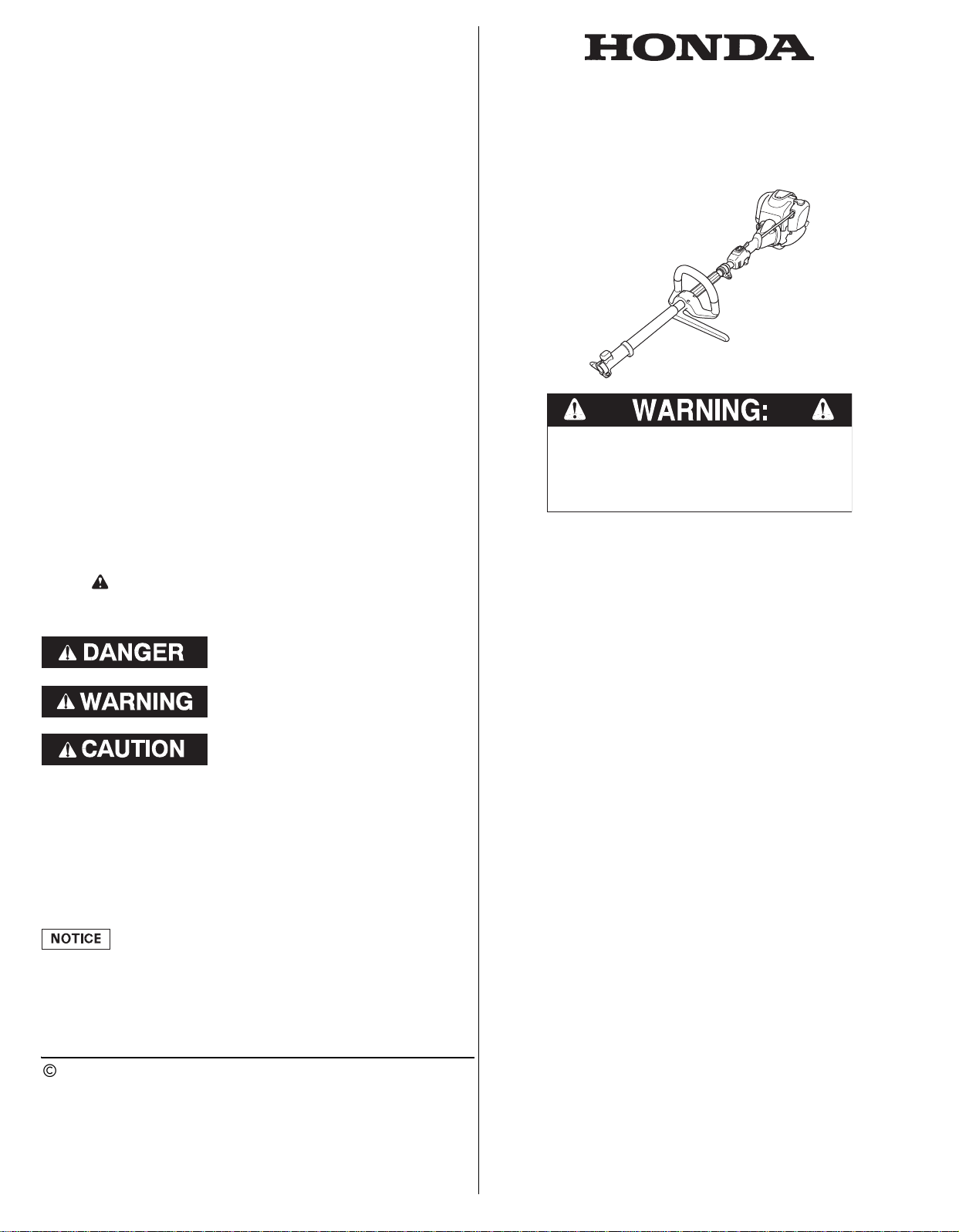
INTRODUCTION
The engine exhaust from this product
contains chemicals known to the State of
California to cause cancer, birth defects or
other reproductive harm.
INTRODUCTION.................... 1
SAFETY MESSAGES.............. 1
SAFETY INFORMATION ......... 2
SAFETY LABEL LOCATION..... 4
COMPONENT & CONTROL
LOCATIONS ......................... 4
CONTROLS .......................... 5
BEFORE OPERATION
CHECKS .............................. 6
OPERATION ......................... 9
SAFE OPERATING
PRECAUTIONS................... 9
STARTING THE ENGINE .... 10
SETTING ENGINE SPEED... 11
STOPPING THE ENGINE .... 11
SERVICING YOUR
POWERHEAD...................... 11
THE IMPORTANCE OF
MAINTENANCE................ 11
MAINTENANCE SAFETY ... 11
SAFETY PRECAUTIONS .... 12
MAINTENANCE
SCHEDULE ...................... 12
REFUELING...................... 13
ENGINE OIL ..................... 13
Recommended Oil.......... 13
Oil Level Check ............. 13
Oil Change.................... 14
AIR CLEANER .................. 15
Inspection..................... 15
Cleaning....................... 15
THROTTLE CABLE............ 15
Check and Adjustment ... 15
Free Play Inspection....... 15
SPARK PLUG....................16
COOLING FINS .................17
FUEL FILTER AND FUEL
TANK ..............................17
FUEL TUBE ......................17
SPARK ARRESTER ............ 18
HELPFUL TIPS &
SUGGESTIONS....................19
STORING YOUR
POWERHEAD ...................19
TRANSPORTING ............... 20
TAKING CARE OF
UNEXPECTED PROBLEMS.....21
TECHNICAL & CONSUMER
INFORMATION ....................21
Serial Number Location......21
Carburetor Modifications for
High Altitude Operation .....22
Emission Control System
Information ......................22
Air Index..........................22
Specifications...................23
Tuneup Specifications ....... 23
Quick Reference
Information ......................23
CONSUMER INFORMATION ... 24
Customer Service
Information ......................24
Click to Save As
Thank you for purchasing a Honda powerhead. We want to help
you to get the best results from your new powerhead and to
operate it safely.
This manual contains information on how to do that; please read it
carefully before operating the powerhead. If a problem should arise,
or if you have any questions about your powerhead, consult an
authorized Honda servicing dealer.
All information in this publication is based on the latest product
information available at the time of printing. Honda Motor Co., Ltd.
reserves the right to make changes at any time without notice and
without incurring any obligation. No part of this publication may be
reproduced without written permission.
This manual should be considered a permanent part of the
powerhead and should remain with the powerhead if resold.
We suggest you read the warranty policy to fully understand its
coverage and your responsibilities of ownership. The warranty
policy is a separate document that should have been given to you
by your dealer.
SAFETY MESSAGES
Your safety and the safety of others are very important. We have
provided important safety messages in this manual and on the
powerhead. Please read these messages carefully.
A safety message alerts you to potential hazards that could hurt
you or others. Each safety message is preceded by a safety alert
symbol and one of three words, DANGER, WARNING, or
CAUTION.
OWNER’S MANUAL
UMC425∙UMC435
POWERHEAD
California Proposition 65
This product contains or emits
chemicals known to the state of
California to cause cancer, birth defects
or other reproductive harm
These signal words mean:
You WILL be KILLED or SERIOUSLY
HURT if you don’t follow instructions.
You CAN be KILLED or SERIOUSLY
Each message tells you what the hazard is, what can happen, and
what you can do to avoid or reduce injury.
DAMAGE PREVENTION MESSAGES
You will also see other important messages that are preceded by
the word NOTICE.
This word means:
The purpose of these messages is to help prevent damage to your
powerhead, other property, or the environment.
The illustrations in this manual are based on: UMC435
• The illustrations may vary according to the type.
2015 Honda Motor Co., Ltd. –All Rights Reserved
31VP8600
00X31-VP8-6000
Your powerhead or other property can be damaged if
you don’t follow instructions.
HURT if you don’t follow instructions.
You CAN be HURT if you don’t follow
instructions.
UMC425A∙UMC435A
CONTENTS
1
Page 2
SAFETY INFORMATION
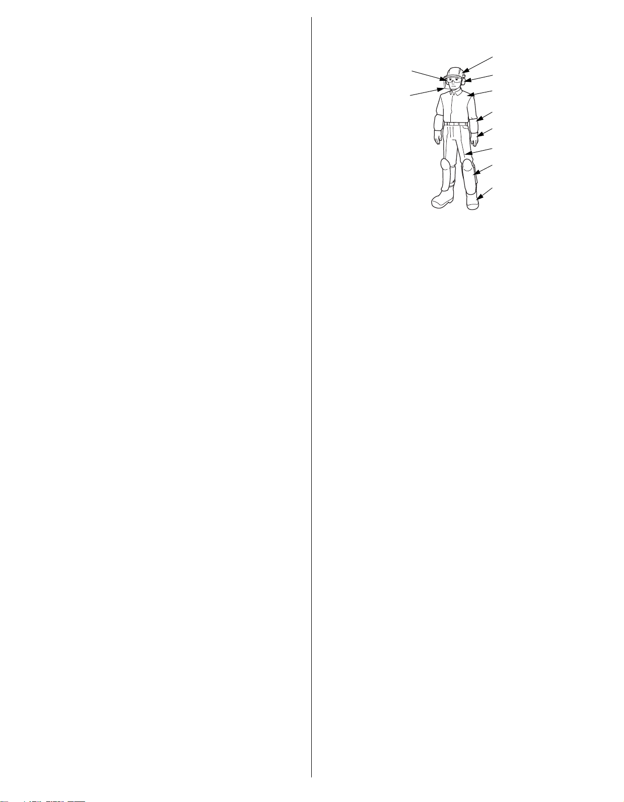
HARD HAT
EAR HEARING
PROTECTION
CLOTHES (LONG SLEEVE)
CLOTHES (LONG PANTS)
LEG PROTECTORS
SAFETY BOOTS (WITH
TOE PROTECTOR)
GLOVES
FACE SHIELD
EYE PROTECTION
ARM COVERS
Operator Responsibility
• Understand the operation of all controls and learn how to stop
the engine quickly in case of an emergency. Make sure the
operator receives adequate instruction before operating the
equipment.
• Do not allow children to operate the powerhead. Keep children
and pets away from the area of operation.
• Your powerhead’s exhaust contains poisonous carbon monoxide.
Do not run the engine without adequate ventilation, and never
run the engine indoors.
• The powerhead and exhaust become very hot during operation.
• Only use Honda approved attachments. If not, injury or accident
may occur.
• Read and follow the instructions in the owner’s manual that
came with each attachment.
• Never operate the powerhead when tired, ill, or under the
influence of alcohol or other drugs.
• Any part of the machine is a potential source of danger if the
machine is used in abnormal conditions or if the maintenance is
not performed correctly.
• If you lend or resell your powerhead to a third person, instruct
him or her on how to handle the product and alert him or her to
read the Owner’s Manual carefully before operation.
• Follow the instructions in the owner’s manual that comes with
each attachment.
• Keep in mind that the operator or user is responsible for any
accidents or hazards that may occur to other people or their
property.
• While operating the powerhead, always wear protective clothing
and protective devices.
• Follow the instructions in the owner’s manual that comes with
each attachment, regarding required protective clothing and
protective devices. For example:
– Protective clothing
Wear adequate clothes with long sleeves and long pants.
Do not wear loose or baggy clothing.
Arm covers and leg protectors should be worn.
Do not wear anything around your neck (for example necklaces
or neckties).
Tie your hair if it is long.
– Protective devices
* Eye protection
Eye protection should meet the requirements of ANSI Z87.1.
Wear goggles or other eye protection to protect your eyes
from flying debris.
*Hard hat
Wear a hard hat to protect your head from any overhead
branches and falling foreign material.
* Face shield
Wear a face shield to protect your face from flying debris.
* Ear hearing protection
To reduce the risk of hearing loss, hearing protection is
required.
*Gloves
Wear gloves to protect your hands.
* Safety boots
Wear safety boots with a non-slip sole and toe protector to
protect your feet from falling objects and flying debris.
Do not operate the equipment barefoot or wearing open
sandals.
* Leg protectors
We recommend that you wear the leg protectors to protect
your legs.
*Dust mask
We recommend that you wear a dust mask to protect
yourself from dusts and pollens.
• Before each use, visually inspect the powerhead for any damage
and looseness of parts.
• Before each use, look around and underneath the engine for signs
of oil or gasoline leaks.
• Avoid operating the powerhead at night, poor visibility or in bad
weather.
• Walk, never run during operation.
• Avoid operating the powerhead on a steep slope.
The steep slope may be slippery, causing you to fall.
• Do not operate the powerhead with any labels, or any parts
removed.
• Do not tamper with the powerhead as it can result in personal
injury and/or equipment damage.
• Only use attachments that are designed for your model and
application.
• Stop the engine with the engine switch to the OFF position in the
following cases:
– Before any operation around the powerhead.
– Before checking, cleaning or working on the powerhead.
– After striking a foreign object. Inspect the powerhead for
damage and make repairs before restarting the powerhead.
– If the powerhead starts to vibrate abnormally. Check
immediately the cause of the vibration and perform the
necessary repair.
– Whenever you leave the powerhead unattended.
– Before refueling.
– When any person or pet is approaching.
– Shut off the engine immediately when the powerhead shows
abnormal vibration suddenly. Sudden vibration can suggest the
damaged rotating parts or loose fasteners. Examine the cause
of the problem, and do not start the engine before a repair is
made.
• The attachment should not be moving when the engine is at idle.
If this happens, contact your authorized Honda dealer. This idle
speed will need to be adjusted. Make sure the cutting attachment
has stopped before the unit is set down.
• Keep all nuts, bolts and screws tight to be sure the powerhead is
in a safe working condition. Regular maintenance is essential to
user’s safety and product performance.
• Do not use the powerhead with worn or damaged parts. Parts
must be replaced, or repaired. Replace worn or damaged parts
with Honda genuine parts. Non equivalent quality parts may
damage the machine and be prejudicial to your safety.
2
Page 3

• Injury caused by vibration and cold:
You may feel the prickling or burning pain in your fingers, and the
fingers may lose color and feeling. It is believed that these
symptoms are brought by vibration and/or exposure to cold. The
specific trigger point of these symptoms are not identified yet,
but observe the following instructions.
* Limit the amount of time you spend operating the powerhead
in a day.
* Keep your body warm, especially your hands, wrists and
arms.
* Take your breaks at short intervals. Do not smoke while
working.
* When you feel discomfort, redness and swelling of the
fingers followed by whitening and loss of feeling, consult
your doctor promptly.
• Injury caused by repeated operation:
Performing the repeated operation for a prolonged time may
cause injury. Observe the following instructions to reduce the
causes of the injury.
* Avoid repeated operation by using your wrist(s) in bent,
stretched or twisted position.
* Take your breaks regularly to minimize the effect of repeated
operation. Take your time when performing repeated
operation. Do not rush to operate the powerhead.
* When your fingers, hands, wrists and/or arms are throbbing
or numbed, consult your doctor.
Carbon Monoxide Hazard
Your powerhead’s exhaust contains poisonous carbon monoxide
gas, which you cannot see or smell. Breathing carbon monoxide
can KILL YOU IN MINUTES,
For your safety:
• Do not start or operate the engine in any closed or partially
enclosed area, such as a garage.
• Never run the powerhead in closed or even partially closed area
where people or pets may be present.
• Never operate the powerhead near open doors, windows, or
vents.
• Get fresh air and seek medical attention immediately if you
suspect you have inhaled carbon monoxide.
Early symptoms of carbon monoxide exposure include headache,
fatigue, shortness of breath, and dizziness. Continued exposure to
carbon monoxide can cause loss of muscular coordination, loss of
consciousness, and then death.
Child Safety
• Keep children indoors and supervised at all times when any
outdoor powerhead is being used nearby.
• Never assume children will remain where you last saw them. Be
alert and turn the powerhead off if children enter the area.
• Children should never be allowed to operate the powerhead, even
under adult supervision.
Fire and Burn Hazard
Gasoline is extremely flammable, and gasoline vapor can explode.
Use extreme care when handling gasoline. Keep gasoline out of
reach of children.
• Store fuel in containers specifically designed for this purpose.
• Refuel outdoors only, and do not smoke while refueling or
handling fuel.
• Add fuel before starting the engine. Never remove the cap of the
fuel tank or add gasoline while the engine is running or when the
engine is hot.
• If gasoline is spilled, do not attempt to start the engine but move
the powerhead away from the area of spillage and avoid creating
any source of ignition until gasoline vapors have dissipated.
• Tighten the fuel tank and container cap securely.
• When you start the engine after refueling, be sure to start the
engine at least 10 feet (3 meter) away from the refueling spot.
• Never store the powerhead with gasoline in the tank inside a
building where fumes may reach an open flame, spark or high
temperature source.
• Allow the engine to cool before storing in any enclosure.
• To reduce a fire hazard, keep the powerhead, especially the
engine, muffler, and gasoline storage area, free of grass, leaves,
or excessive grease.
• If the fuel tank has to be drained, this should be done outdoors,
with a cold engine.
3
Page 4
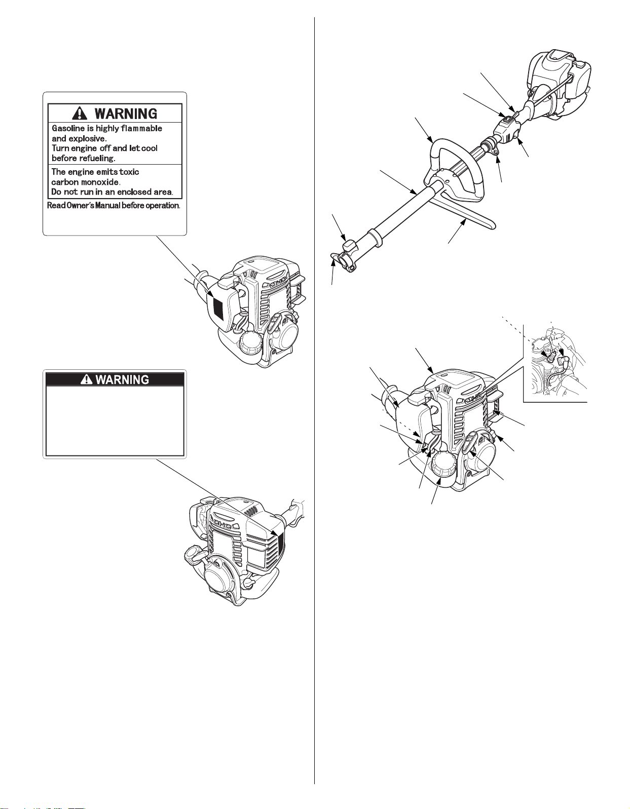
SAFETY LABEL LOCATION
Operation of This Equipment May Create
Sparks That Can Start Fires Around Dry
Vegetation. A Spark Arrestor May be
Required. The Operator Should Contact
Local Fire Agencies For Laws or
Regulations Relating to Fire Prevention
Requirements.
Per California Public Resources Code 4442.6
THROTTLE TRIGGER
INTERLOCK
ENGINE SWITCH
LOOP HANDLE
MAIN PIPE
SET PIN KNOB
JOINT KNOB
PROTECTOR
HANGER
THROTTLE TRIGGER
SPARK PLUG
SPARK PLUG CAP
(inside the top cover)
TOP COVER
AIR CLEANER
PRIMING PUMP
CHOKE LEVER
FUEL RETURN TUBE
(TRANSPARENT TUBE)
FUEL TUBE (BLACK TUBE)
FUEL TANK CAP
STARTER GRIP
ENGINE OIL FILLER CAP
MUFFLER
These labels warn you of potential hazards that can cause serious
injury. Read them carefully.
If a label comes off or becomes hard to read, contact your Honda
servicing dealer for replacement.
COMPONENT & CONTROL LOCATIONS
* The following Honda approved attachments can be used with the
powerhead. Consult your servicing dealer.
• Trimmer/Brush
• Edger
∙∙∙etc.
4
Page 5
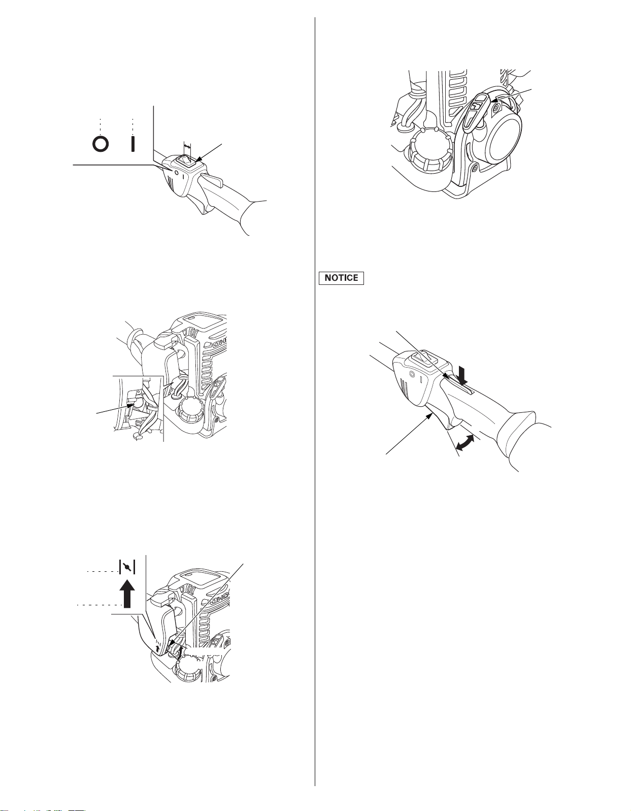
CONTROLS
OFF ON
ENGINE SWITCH
OFF
ON
PRIMING PUMP
CHOKE LEVER
OPEN
CLOSED
OPEN
CLOSED
STARTER GRIP
THROTTLE TRIGGER
INTERLOCK
FAST
SLOW
THROTTLE TRIGGER
Starter Grip
Engine Switch
The engine switch enables and disables the ignition system.
The engine switch must be in the ON position for the engine to run.
Moving the engine switch to the OFF position stops the engine.
Priming Pump
Pressing the priming pump feeds the gasoline from the fuel tank to
the carburetor. This procedure is necessary for starting the engine
(see page 10).
Pulling the starter grip operates the recoil starter to crank the
engine for starting.
Throttle Trigger
The throttle trigger controls engine speed.
Pulling and releasing the throttle trigger shown below makes the
engine run faster or slower.
The throttle trigger interlock must be depressed before the throttle
trigger can be activated.
Choke Lever
The choke lever opens and closes the choke valve in the
carburetor.
The CLOSED position enriches the fuel mixture for starting a cold
engine.
The OPEN position provides the correct fuel mixture for operation
after starting, and for restarting a warm engine.
By pulling the throttle trigger gradually, the engine speed increases
gradually.
Pull the throttle trigger more to accelerate the engine speed.
By releasing the throttle trigger, the engine speed decreases.
Throttle Trigger Interlock:
The throttle trigger interlock makes the throttle trigger operable.
The throttle trigger cannot be pulled unless the throttle trigger
interlock has been pushed beforehand.
5
Page 6
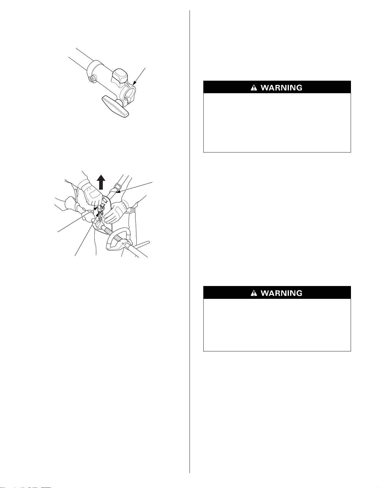
Joint
JOINT
QUICK-RELEASE LATCH TAB
CARRYING
HARNESS
QUICK-RELEASE LATCH
BEFORE OPERATION CHECKS
The joint is to attach a Honda approved attachment to the
powerhead.
Refer to Pages 7–8 for how to attach and detach the attachments.
Carrying Harness Quick-Release Latch
The quick-release latch tab is provided to detach the powerhead
from your body in an emergency.
Pull up the quick-release latch tab, and the powerhead is detached
from the carrying harness.
IS YOUR POWERHEAD READY TO GO?
For your safety, to ensure compliance with environmental
regulations, and to maximize the service life of your equipment, it is
very important to take a few moments before you operate the
powerhead to check its condition. Be sure to take care of any
problem you find, or have your servicing dealer correct it, before
you operate the powerhead.
Improperly maintaining this powerhead, or failing to
correct a problem before operation, could cause a
malfunction.
Some malfunctions can seriously hurt or kill you.
Always perform a pre-operation inspection before
each operation and correct any problems.
Before beginning your pre-operation checks, be sure the powerhead
is level and the engine switch is in the OFF position.
Always check the following items before you start the engine:
Check the General Condition of the Powerhead
1. Before each use, look around and underneath the engine for
signs of oil or gasoline leaks.
2. Remove any excessive dirt or debris, especially around the
muffler and recoil starter.
3. Look for signs of damage.
4. Check that all shields and covers are in place, and all nuts,
bolts, and screws are tightened.
Adjustment of the Carrying Harness
Failure to wear the carrying harness while using the
powerhead could result in instability.
Injuries may occur due to instability.
Be sure to wear the carrying harness before using the
powerhead.
1. Wear the carrying harness so that the hip pad is on the right
side of your body.
• Make sure the harness does not twist.
• If the carrying harness is for both shoulders, firmly secure the
carrying harness latch on the front of your body until it clicks.
To unlock the carrying harness latch, pull the harness to the
right and to the left while pressing the latch.
6
Page 7
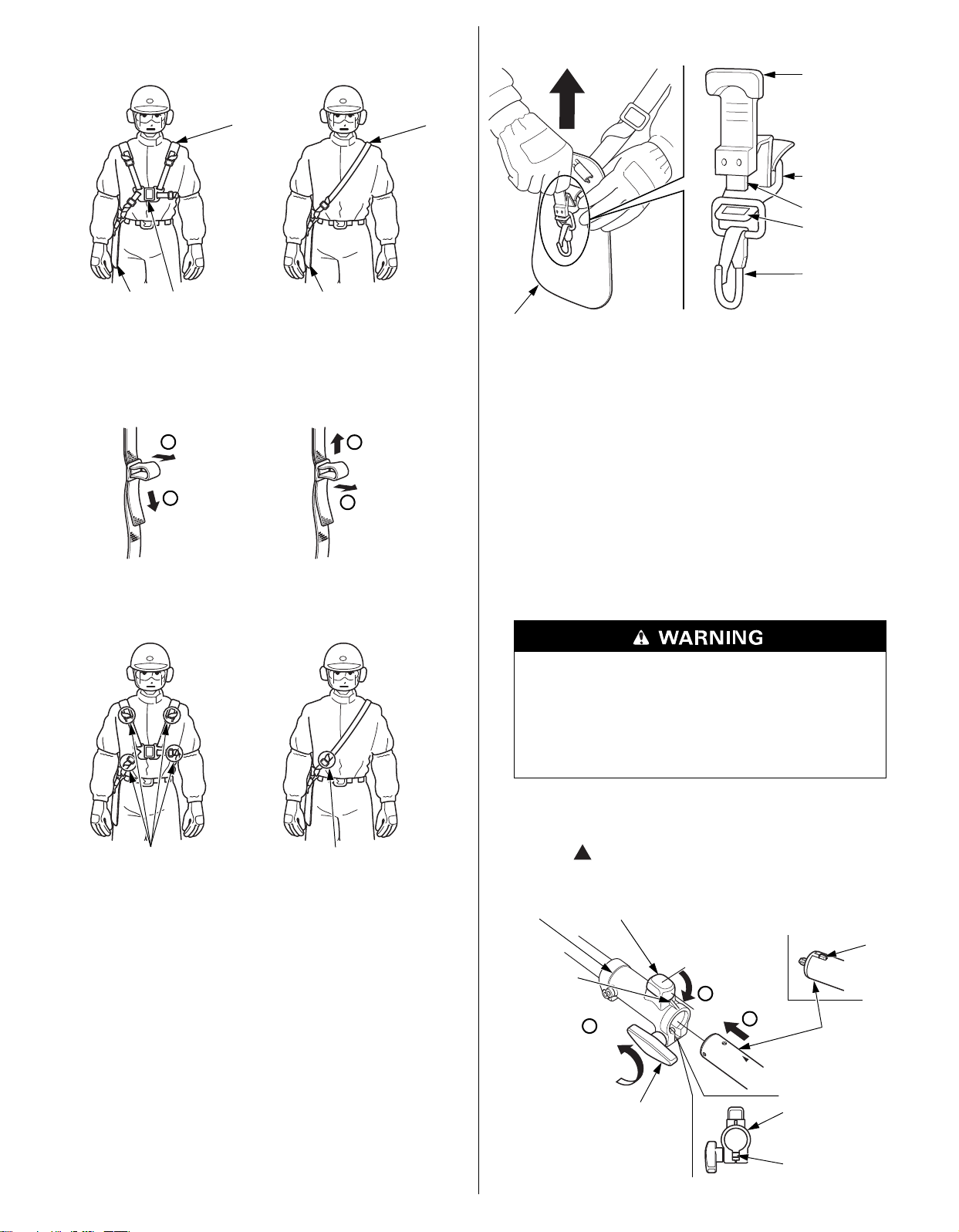
2. Adjust the length of the harness as shown in the figures below.
For both shoulders
(UMC435)
For single shoulders
(UMC425)
CARRYING
HARNESS
CARRYING
HARNESS
HIP PAD
CARRYING
HARNESS
LATCH
HIP PAD
To make it shorter To make it longer
1
2
2
1
(UMC435) (UMC425)
Roll the end of the
harness and fasten it.
(There is one applicable
point on the back side of
your body)
Roll the end of the
harness and fasten it.
QUICK-RELEASE
LATCH TAB
HOOK
QUICK-RELEASE
LATCH
HIP PAD
LATCH TONGUE
SLOT
JOINT HOLDER SET PIN KNOB (Back side of the portion where
the attachment is connected)
KEY
PROJECTION
JOINT KNOB
ATTACHMENT
JOINT HOLDER
GROOVE
LOOSEN
LOCK
1
2
3
3. Insert the latch tongue in the slot of the quick-release latch to
reattach the powerhead to the carrying harness.
If the latch is not released, have your device inspected and repaired
by your servicing dealer.
Attachment Installation/Removal
Check the joint area:
1. Check to see if the set pin knob moves smoothly.
3. Roll the end of the harness toward your body and fasten it.
Check the Quick-Release Latch
1. Put on the carrying harness.
2. Check that the latch is released as soon as the quick-release
latch tab is pulled upwards while holding the hip pad with your
left hand.
2. Check to see if the joint knob tightens and loosens smoothly,
and if there is any damage.
3. Make sure there is no debris in the groove and inside the joint
holder.
Installation:
Running this engine without an attachment in place
could cause an unsafe condition.
Moving parts could cause severe injury.
Do not run the engine without an attachment properly
secured.
1. Turn the set pin knob to the lock position and loosen the joint
knob.
2. Align the “ ” mark on the attachment with the joint projection
which also aligns the key of the attachment with the joint
groove.
7
Page 8
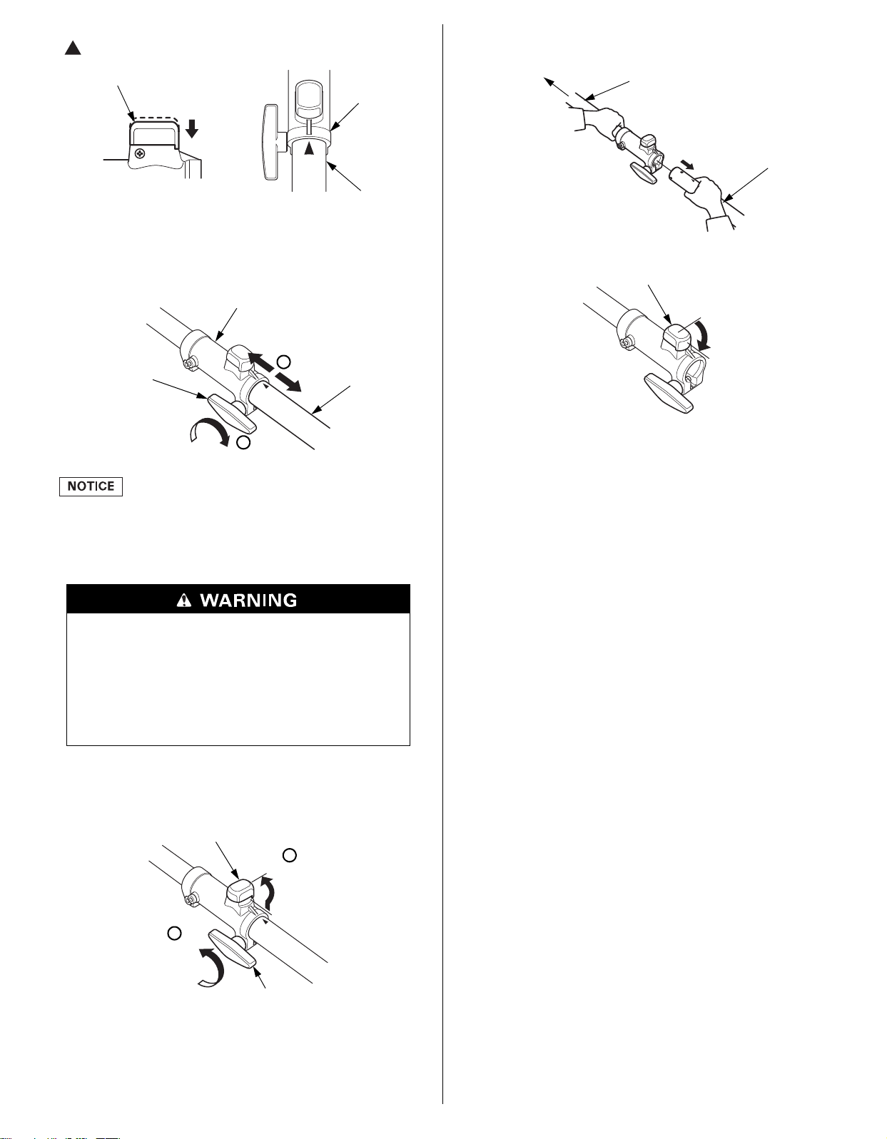
3. Insert the attachment until the set pin knob clicks. Confirm the
JOINT HOLDER
ATTACHMENT
SET PIN KNOB
JOINT HOLDER
ATTACHMENT
JOINT KNOB
TIGHTEN
4
5
SET PIN KNOB
UNLOCK
JOINT KNOB
LOOSEN
1
2
MAIN PIPE
ATTACHMENT
POWERHEAD SIDE
SET PIN KNOB
LOCK
“ ” mark on the attachment is at the joint holder end.
4. Pull the attachment and joint holder to the arrow direction to
check that the attachment will not come loose.
5. Tighten the joint knob.
3. Hold the main pipe on the powerhead side and detach the
attachment.
4. Turn the set pin knob to the lock position.
Check the Engine
When you place the powerhead with the recoil starter facing
down, be careful not to damage the recoil starter. Recoil starter
or the engine might get damaged from the impact.
Removal:
Be sure to turn the engine switch to the OFF position.
The attachment will continue to move briefly after the
engine has stopped or the throttle trigger is released.
A moving attachment can cause injury.
Maintain proper control of the powerhead until the
attachment has completely stopped moving.
1. Loosen the joint knob.
2. Pull the set pin knob up and twist 90 degrees to the unlock
position.
1. Check the fuel level (see page 13). Starting with a full tank will
help to eliminate or reduce operating interruptions for refueling.
2. Check the engine oil level (see page 13). Running the engine
with a low oil level can cause engine damage.
3. Check the air filter element (see page 15). A dirty air filter
element will restrict air flow to the carburetor, reducing engine
and powerhead performance. A damaged air filter element will
allow dust to enter and damage the engine.
4. Check the throttle cable free play (see page 15). Operate the
throttle system several times and check if it the free play (i.e.
throttle lever does not move while operating the throttle
trigger).
8
Page 9
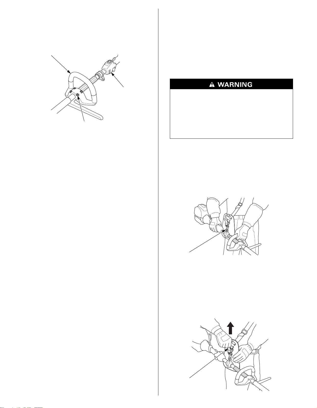
Check All Bolts and Nuts
THROTTLE ASSEMBLY
HANDLE MOUNTING BOLTS (4)
LOOP HANDLE
HOOK
QUICK-RELEASE
LATCH TAB
OPERATION
1. Check each bolt and nut for looseness. Tighten them securely if
necessary.
2. Check the handle for loose mounting bolts, and tighten them
securely if necessary.
SAFE OPERATING PRECAUTIONS
Before operating the powerhead for the first time, please review
the SAFETY INFORMATION (see pages 2–3) and the BEFORE
OPERATION CHECKS (see pages 6–9).
For your safety, do not operate the powerhead in an enclosed area
such as a garage. Your powerhead’s exhaust contains poisonous
carbon monoxide gas that can collect rapidly in an enclosed area
and cause illness or death.
Exhaust contains poisonous carbon monoxide gas
that can build up to dangerous levels in closed areas.
Breathing carbon monoxide can cause
unconsciousness or death.
Never run the powerhead in a closed, or even partly
closed area where people may be present.
Read and understand the safety instructions on pages 6 to 9 before
operating the powerhead.
If you notice any abnormal sound, smell, vibration, or other unusual
signs, stop the engine immediately and consult your authorized
Honda dealer.
With the engine idling, hook the powerhead to your carrying
harness and hold the powerhead at the correct position.
Hold the powerhead firmly with both hands, with your fingers and
thumbs encircling the handles as shown. This will help you to keep
the powerhead under control at all times.
For how to use the attachment, read and follow the instructions in
the owner’s manual that came with each attachment.
In an emergency, pull up on the quick-release latch tab to detach
the powerhead from the carrying harness.
9
Page 10
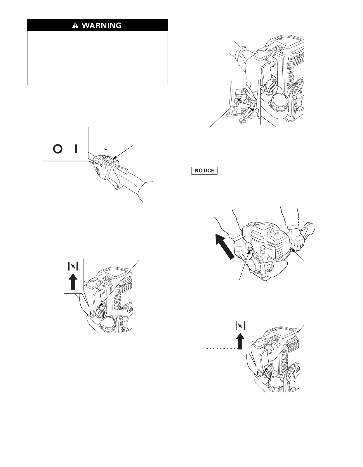
STARTING THE ENGINE
ENGINE SWITCH
ON
ON
CHOKE LEVER
CLOSED
OPEN
OPEN
CLOSED
PRIMING PUMP FUEL RETURN TUBE
(TRANSPARENT TUBE)
STARTER GRIP
MAIN PIPE
Direction to pull
CHOKE LEVER
OPEN
OPEN
Exhaust contains poisonous carbon monoxide gas
that can build up to dangerous levels in closed areas.
Breathing carbon monoxide can cause
unconsciousness or death.
Never run the powerhead in a closed, or even partially
closed area where people may be present.
Start the engine in a place away from the people, pets, and
surrounding buildings. Be sure there are no obstacles in the
working area.
1. Move the engine switch to the ON position.
3. To start a cold engine, press the priming pump several times
until a flow in the fuel return tube (transparent tube) is visually
noticed.
4. Pull the starter grip lightly until you feel resistance while holding
the main pipe, then pull briskly in the direction of the arrow as
shown below. Return the starter grip gently.
Do not allow the starter grip to snap back against the engine.
Return it gently to prevent damage to the starter.
Damage may result if the starter grip is pulled while the engine
is running.
2. To start a cold engine, move the choke lever to the CLOSED
position.
To restart warm engine, leave the choke lever in the OPEN
position.
Do not use the choke if the engine is warm or the air
temperature is high.
5. If the choke lever has been moved to the CLOSED position to
start the engine, gradually move it to the OPEN position as the
engine warms up.
10
Hot Restart
If the engine is operated at higher ambient temperatures, then
turned off and allowed to sit for a short time, it may not restart on
the first pull.
If necessary, use the following procedure:
Page 11
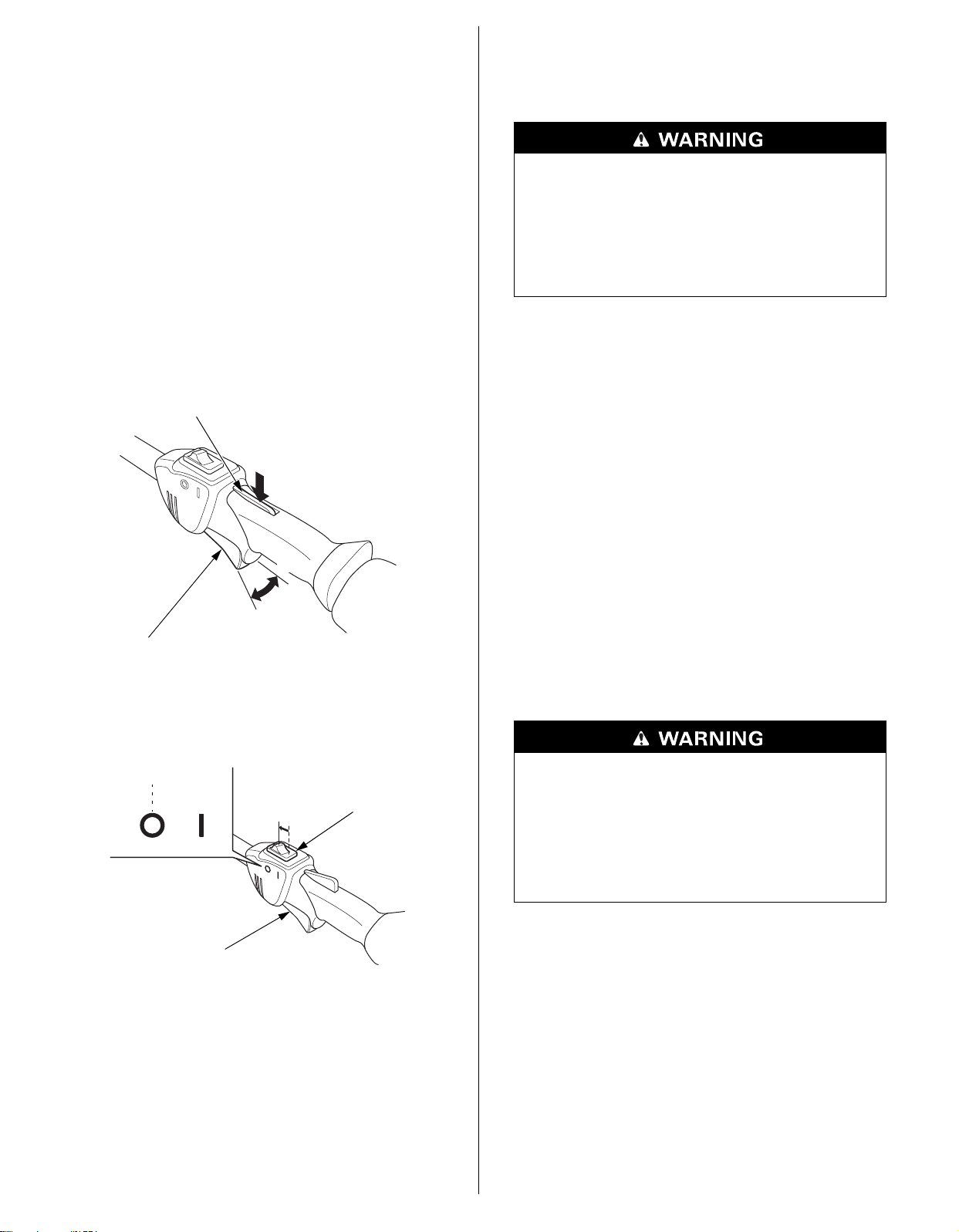
IMPORTANT SAFETY PRECAUTION
THROTTLE TRIGGER INTERLOCK
THROTTLE TRIGGER
FAST
SLOW
ENGINE SWITCH
OFF
OFF
THROTTLE TRIGGER
Turn the engine switch to the OFF position before performing the
following procedure. This will prevent the engine from starting and
running at maximum speed when the throttle trigger is in the FAST
speed position. If the engine starts with the throttle trigger in the
FAST speed position, the equipment can move forward rapidly or
the attachment can spin at maximum speed.
SERVICING YOUR POWERHEAD
THE IMPORTANCE OF MAINTENANCE
Good maintenance is essential for safe, economical and troublefree operation. It will also help reduce pollution.
1. Turn the engine switch to the OFF position.
2. Move the choke lever to the OPEN position.
3. Hold the throttle trigger in the FAST speed position.
4. Pull the starter grip 3 to 5 times.
Follow the STARTING THE ENGINE procedure on page 10 and start
the engine with the choke lever in the OPEN position.
SETTING ENGINE SPEED
Squeeze the throttle trigger for the desired engine speed.
Improperly maintaining this powerhead, or failing to
correct a problem before operation, could cause a
malfunction.
Some malfunctions can seriously hurt or kill you.
Always perform a pre-operation inspection before
each operation, and correct any problem.
To help you properly care for your powerhead, the following pages
include a maintenance schedule, routine inspection procedures, and
simple maintenance procedures using basic hand tools. Other
service tasks that are more difficult, or require special tools, are
best handled by professionals and are normally performed by a
Honda technician or other qualified mechanic.
The maintenance schedule applies to normal operating conditions.
If you operate your powerhead under severe conditions, such as
sustained high-load or high-temperature operation, or use in
unusually wet or dusty conditions, consult your Honda servicing
dealer for recommendations applicable to your individual needs and
use.
Maintenance, replacement, or repair of the emission control
devices and systems may be performed by any powerhead repair
establishment or individual, using parts that are ‘‘certified’’ to EPA
standards.
STOPPING THE ENGINE
1. Release the throttle trigger.
2. Move the engine switch to the OFF position.
MAINTENANCE SAFETY
Some of the most important safety precautions follow. However,
we cannot warn you of every conceivable hazard that can arise in
performing maintenance. Only you can decide whether or not you
should perform a given task.
Improper maintenance can cause an unsafe condition.
Failure to properly follow maintenance instructions
and precautions can cause you to be seriously hurt or
killed.
Always follow the procedures and precautions in this
owner’s manual.
11
Page 12

SAFETY PRECAUTIONS
• Make sure the powerhead is off before you begin any
maintenance or repairs. To prevent unintentional startup,
disconnect the spark plug cap. This will eliminate several
potential hazards:
– Carbon monoxide poisoning from engine exhaust.
Operate outside, away from open windows or doors.
– Burns from hot parts.
Let the engine and exhaust system cool before touching.
– Injury from moving parts.
Do not run the engine unless instructed to do so.
• Read the instructions before you begin, and make sure you have
the tools and skills required.
• To reduce the possibility of fire or explosion, be careful when
working around gasoline. Use only a non-flammable solvent, not
gasoline, to clean parts. Keep cigarettes, sparks and flames away
from all fuel related parts.
Remember that an authorized Honda servicing dealer knows your
powerhead best and is fully equipped to maintain and repair it.
To ensure the best quality and reliability, use only new Honda
Genuine parts or their equivalents for repair and replacement.
MAINTENANCE SCHEDULE
REGULAR SERVICE PERIOD (1)
ITEM
Engine oil Check level o 13
Air cleaner Check o 15
Spark plug Check-adjust o
Throttle cable Check
Throttle trigger Check
Engine cooling fins Check Clean o
Shoulder harness
quick-release
Set pin knob Check o 7
Joint knob Check o 7
Around the joint
holder
Nuts, bolts,
fasteners
Spark arrester Check Clean o 18
Fuel tank Clean o 17
Fuel filter Clean o 17
Clutch shoes Check o (2) –
Idle speed Check-adjust o (2) –
Valve clearance Check-adjust o (2) –
Timing belt Check After every 300 hrs. (2) (4) –
Combustion
chamber
Fuel tubes Check Every 2 ye ars (Replace if necessary) (2) –
Oil tube Check Every 2 years (Replace if necessary) (2) –
Perform at every
indicated month or
operating hour interval,
whichever comes first.
Change
Clean
Replace o
Check
Check
Check
(Retighten if
necessary)
Clean
Each
First
Every 3
use
month
or
10 hrs.
oo
o15
o16
o7
o7
o9
Every 6
months
months
or
o (3)
or
50 hrs.
25 hrs.
Every 300 hrs. (2) –
Every
year
or
100 hrs.
Every 2
years
or
300 hrs.
Refer
to
Page
14
15
16
17
(1) For professional commercial use, log hours of operation to
determine proper maintenance intervals.
(2) These items should be serviced by your servicing dealer,
unless you have the proper tools and are mechanically
proficient.
Refer to Honda shop manual for service procedures.
(3) Service more frequently when used in dusty areas.
(4) Check that there is no crack and abnormal wear-out in the
belt, and replace if it is abnormal.
Failure to follow this maintenance schedule could result in
non-warrantable failures.
12
Page 13
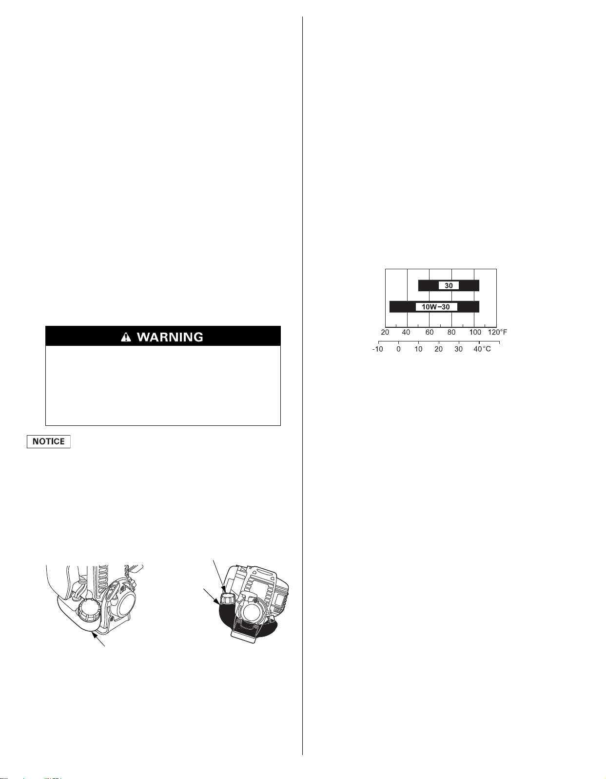
REFUELING
FUEL TANK CAP
FUEL TANK
UPPER FUEL
LIMIT LEVEL
AMBIENT TEMPERATURE
Recommended Fuel
This engine is certified to operate on unleaded gasoline with a
pump octane rating of 86 or higher.
Refuel in a well ventilated area with the engine stopped. If the
engine has been running, allow it to cool first. Never refuel the
engine inside a building where gasoline fumes may reach flames or
sparks.
To refuel, rest the engine a level surface with the fuel tank cap
facing up, as shown. Remove the fuel tank cap, and fill the tank
with gasoline to the bottom of the filler neck. Refuel carefully to
avoid spilling fuel. Do not overfill. There should be no fuel in the
filler neck. After refueling, tighten the fuel tank cap securely.
Keep gasoline away from appliance pilot lights, barbecues, electric
appliances, power tools, etc.
Spilled fuel is not only a fire hazard, it causes environmental
damage. Wipe up spills immediately.
You may use unleaded gasoline containing no more than 10%
ethanol (E10) or 5% methanol by volume. In addition, methanol
must contain cosolvents and corrosion inhibitors. Use of fuels with
content of ethanol or methanol greater than shown above may
cause starting and/or performance problems. It may also damage
metal, rubber, and plastic parts of the fuel system. Engine damage
or performance problems that result from using a fuel with
percentages of ethanol or methanol greater than shown above are
not covered under the Warranty.
If your equipment will be used on an infrequent or intermittent
basis, please refer to the ‘‘Fuel’’ section of the ‘‘STORING YOUR
POWERHEAD’’ chapter (see page 19) for additional information
regarding fuel deterioration.
Never use stale or contaminated gasoline or an oil/gasoline mixture.
Avoid getting dirt or water in the fuel tank.
Gasoline is highly flammable and explosive, and you
can be burned or seriously injured when refueling.
• Stop the engine and let cool before refueling.
• Keep heat, sparks, and flame away.
• Refuel only outdoors.
• Wipe up spills immediately.
ENGINE OIL
Oil is a major factor affecting performance and service life.
Use 4-stroke automotive detergent oil.
Recommended Oil
Use 4-stroke motor oil that meets or exceeds the requirements for
API service classification SJ or later (or equivalent). Always check
the API service label on the oil container to be sure it includes the
letters SJ or later (or equivalent).
SAE 10W-30 is recommended for general use. Other viscosities
shown in the chart may be used when the average temperature in
your area is within the indicated range.
Fuel can damage paint and some types of plastic. Be careful not to
spill fuel when filling your fuel tank. Damage caused by spilled fuel
is not covered under the Distributor’s Limited Warranty.
1. Check the fuel level by looking through the translucent fuel
tank.
2. If the fuel level is low, refuel in a well-ventilated area with the
engine stopped. If the engine has been running, allow it to cool.
Oil Level Check
Check the engine oil level before each use, or every 10 hours if
operated continuously.
Check the engine oil level with the engine stopped and in a level
position.
1. Remove the engine oil filler cap and wipe it clean.
2. Check the oil level. If it is below the upper limit, fill with the
recommended oil to the upper limit. Do not overfill.
13
Page 14
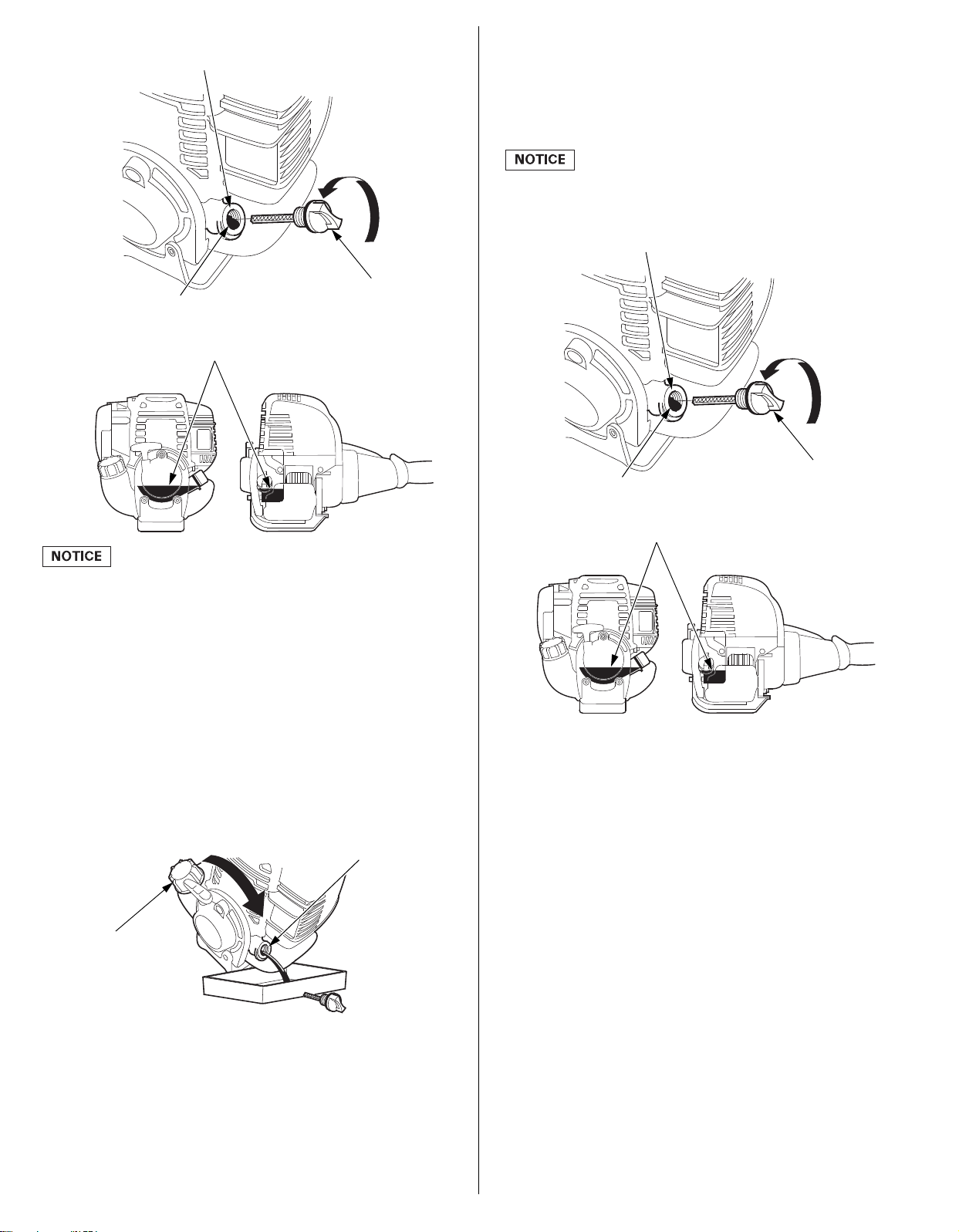
3. Reinstall the engine oil filler cap and tighten securely.
UPPER LIMIT
ENGINE OIL
FILLER CAP
UPPER LIMIT
OIL FILLER NECK
FUEL TANK CAP
OIL FILLER NECK
UPPER LIMIT
ENGINE OIL
FILLER CAP
UPPER LIMIT
OIL FILLER NECK
4. With the powerhead in a level position, fill to the bottom edge
of the oil fill hole with the recommended oil (see page 13).
Some oil will remain in the powerhead after draining. When
refilling with fresh oil, start with UMC425: 2.7 oz (0.08 L),
UMC435: 3.3 oz (0.10 L). Slowly add enough oil to fill to the
bottom edge of the oil fill hole as shown below. Do not overfill.
Running the engine with a low or excessive oil level can cause
engine damage. This type of damage is not covered by the
Distributor’s Limited Warranty.
Running the engine with a low oil level can cause engine damage.
This type of damage is not covered by the Distributor’s Limited
Warranty.
Oil Change
Drain the used oil when the engine is warm. Warm oil drains
quickly and completely.
1. Check that the fuel tank cap is tightened securely.
2. Place a suitable container below the powerhead to catch the
used oil.
3. Remove the engine oil filler cap and drain the oil into the
container by tipping the powerhead toward the oil filler neck.
5. Reinstall the engine oil filler cap securely. If any oil is spilled,
make sure to wipe it up.
Please dispose of used motor oil in a manner that is compatible
with the environment. We suggest you take used oil in a sealed
container to your local recycling center or service station for
reclamation. Do not throw it in the trash, pour it on the ground,
or pour it down a drain.
14
Page 15
AIR CLEANER
AIR CLEANER ELEMENT
CHOKE LEVER
LOWER TABS
AIR CLEANER COVER
UPPER TAB
Squeeze and dry SqueezeDip in oilClean
Do not twist. Do not twist.
UPPER TAB
AIR CLEANER COVER
LOWER TABS CHOKE LEVER
THROTTLE LEVER
FIXING NUT
FREE PLAY:
0.02
–0.10 in
(0.5
–2.5 mm)
TIP OF THE THROTTLE CABLE
THROTTLE CABLE
ADJUSTING NUT
Pull out
lightly
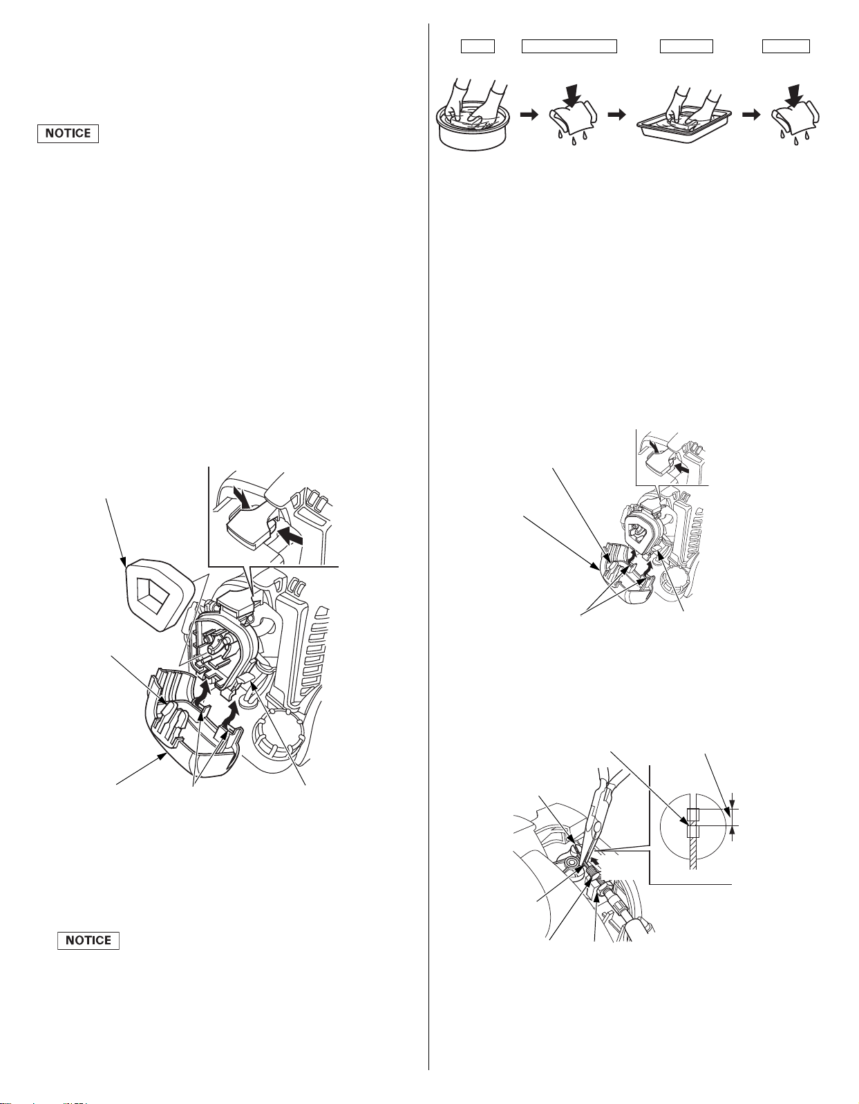
A dirty air cleaner will restrict air flow to the carburetor, reducing
engine performance. If you operate the powerhead in very dusty
areas, clean the air filter element more often than specified in the
MAINTENANCE SCHEDULE.
Operating the engine without an air filter element, or with a
damaged air filter element, will allow dirt to enter the engine,
causing rapid engine wear. This type of damage is not covered by
the Distributor’s Limited Warranty.
Inspection
1. Move the choke lever to the CLOSED (upwards) position.
2. Remove the air cleaner cover by unhooking the upper tab on the
top of the air cleaner cover and its two lower tabs.
2. Reinstall the air cleaner element.
3. Reinstall the air cleaner cover by inserting the lower tabs, then
insert the upper tab.
THROTTLE CABLE
Check and Adjustment
Adjust the throttle cable free play properly.
3. Check the air cleaner element for deterioration, damage, dirt or
obstruction. Clean the air cleaner element, if it is dirty or replace
it if it is damaged.
4. Reinstall the air cleaner element. Make sure it is properly
positioned and seated against the air cleaner case.
5. Reinstall the air cleaner cover by inserting the lower tabs, then
insert the upper tab.
Free Play Inspection
1. Move the choke lever to the CLOSED (upwards) position.
2. Remove the air cleaner cover by unhooking the upper tab on the
top of the air cleaner cover and its two lower tabs.
3. Pull out the throttle cable lightly and turn the adjusting nut to
adjust the extended length of the throttle cable at the end of the
cable to 0.02–0.10 in (0.5–2.5 mm). (Take care not to damage
the throttle cable.)
Cleaning
1. Clean in warm soapy water, rinse and allow to dry thoroughly.
Or use a high flash point solvent, allow to dry. Dip the element
in clean engine oil and squeeze out all the excess.
The engine will smoke during initial startup if too much oil is left
in the foam.
Do not install a dry air filter without any oil applied. Doing so
will allow dust to enter the engine, resulting in rapid engine
wear, which is not covered by warranty.
4. Tighten the throttle cable fixing nut securely.
15
Page 16
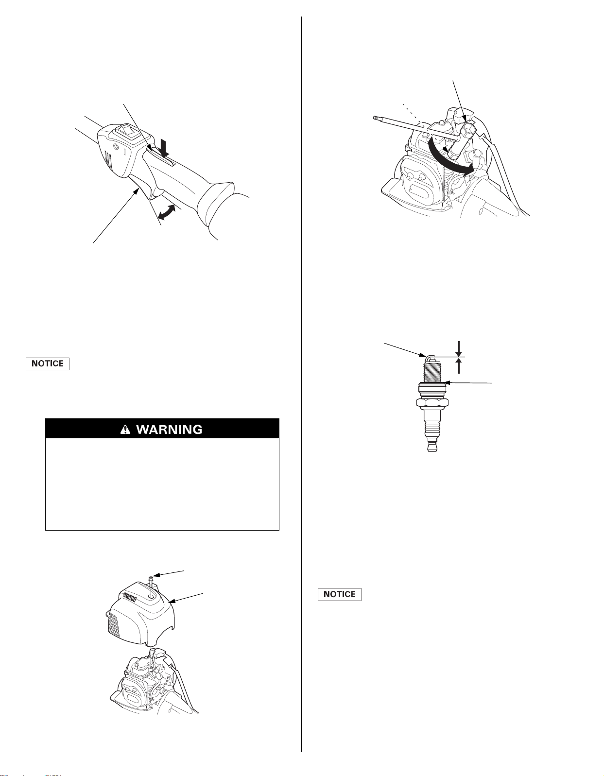
5. Operate the throttle system several times and check if it has
THROTTLE TRIGGER INTERLOCK
THROTTLE TRIGGER
TOP COVER
5 mm SOCKET BOLT
SPARK PLUG WRENCH
SPARK PLUG
SIDE ELECTRODE
0.024–0.028 in
(0.6–0.7 mm)
SEALING WASHER
free play (i.e. throttle trigger does not move while operating the
throttle trigger interlock).
After adjustment, check the throttle trigger for smooth
operation.
Consult your authorized Honda dealer if necessary.
6. Reinstall the air cleaner cover by inserting the lower tabs, then
insert the upper tab.
SPARK PLUG
Recommended Spark Plug: CMR5H (NGK)
2. Disconnect the spark plug cap, and remove any dirt from
around the spark plug area.
3. Remove the spark plug with a 5/8-inch spark plug wrench.
4. Inspect the spark plug.
Replace it if damaged or badly fouled, if the sealing washer is in
poor condition, or if the electrode is worn.
5. Measure the spark plug electrode gap with a wire-type feeler
gauge. Correct the gap, if necessary, by carefully bending the
side electrode.
The gap should be:
0.024–0.028 in (0.6–0.7 mm)
The recommended spark plug has the correct heat range for normal
engine operating temperatures.
An incorrect spark plug can cause engine damage.
For good performance, the spark plug must be properly gapped and
free of deposits.
Do not operate the engine when the top cover is
removed.
Do not pull the recoil starter handle when the top
cover is removed.
You may be injured from the rotating parts or burned
by the muffler or other engine components.
1. Loosen the 5 mm socket bolt with a hexagon wrench, then
remove the top cover.
6. Install the spark plug carefully, by hand, to avoid crossthreading.
7. After the spark plug is seated, tighten with a 5/8-inch spark
plug wrench to compress the sealing washer.
When installing a new spark plug, tighten 1/2 turn after the
spark plug seats to compress the washer.
When reinstalling the original spark plug, tighten 1/8–1/4 turn
after the spark plug seats to compress the washer.
A loose spark plug can overheat and damage the engine.
Overtightening the spark plug can damage the threads in the
cylinder head.
16
TORQUE: 11.8 Nm (1.2 kgf∙m, 8.7 lbf∙ft)
8. Attach the spark plug cap to the spark plug.
9. Install the top cover, and tighten the 5 mm socket bolt securely
with a hexagon wrench.
Page 17
COOLING FINS
COOLING FINS
(Inside the top cover)
5 mm SOCKET BOLT
TOP COVER
ENGINE OIL FILLER CAP
FUEL FILLER NECK
FUEL TANK CAP
FUEL FILTER
FUEL TUBES
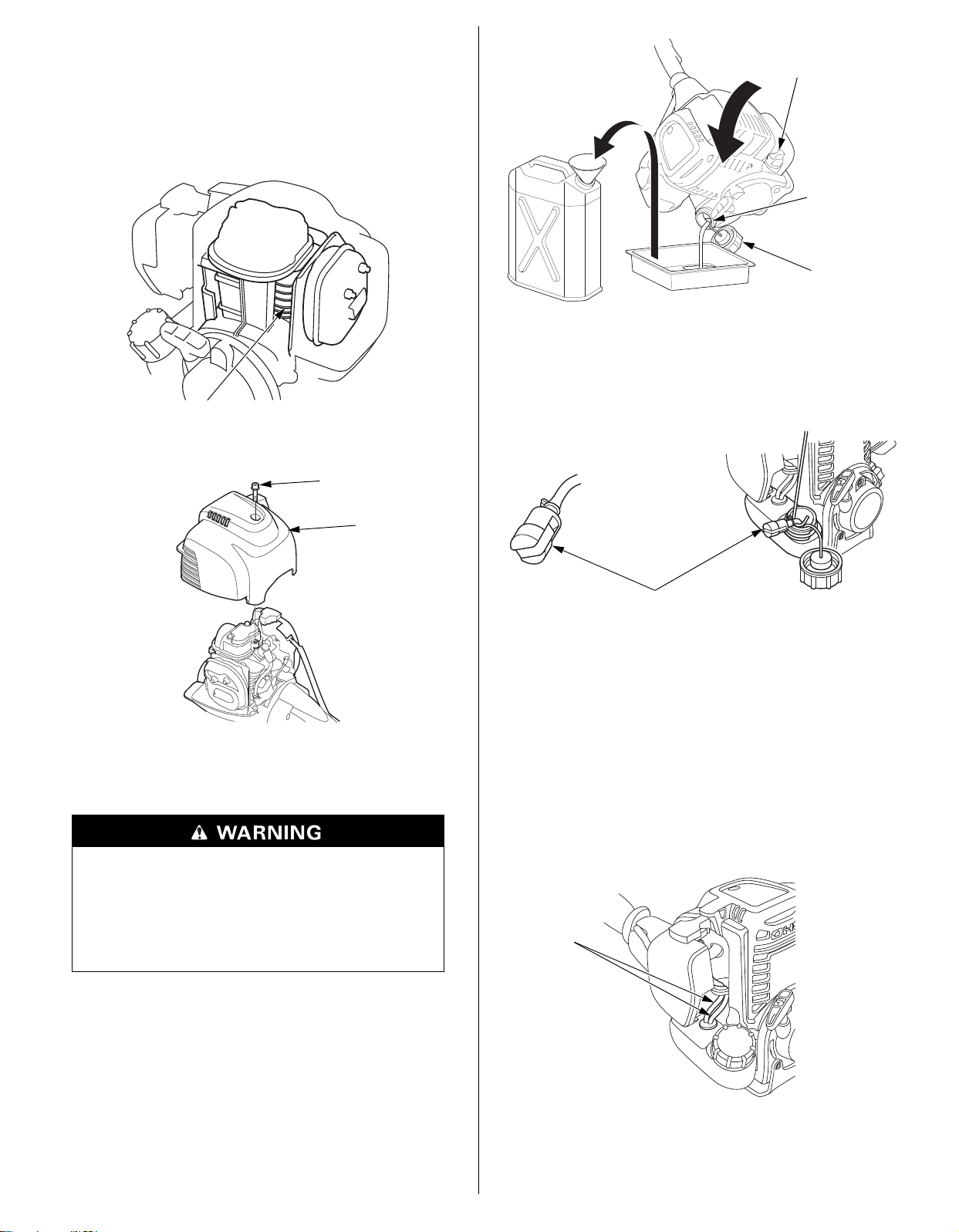
Inspection
1. Loosen the 5 mm socket bolt, then remove the top cover.
2. Inspect the engine cooling fins, and clean out debris if
necessary.
3. Install the top cover, and tighten the 5 mm socket bolt securely.
3. Pull out the fuel filter with the mechanic’s wire from the fuel
filler neck gently.
4. Inspect the fuel filter. If the fuel filter is dirty, wash it gently
with non-flammable or high flash point solvent. If the fuel filter
is excessively dirty, replace it.
FUEL FILTER AND FUEL TANK
Fuel filter inspection and Fuel tank cleaning
Gasoline is highly flammable and explosive, and you
can be burned or seriously injured when refueling.
• Stop the engine and let cool before refueling.
• Keep heat, sparks, and flame away.
• Refuel only outdoors.
• Wipe up spills immediately.
1. Check that the engine oil filler cap is tightened securely.
2. Remove the fuel tank cap, and drain the fuel into an approved
gasoline container by tipping the powerhead toward the fuel
filler neck.
5. Remove water and dirt from the fuel tank by rinsing the inside
of the fuel tank with non-flammable or high flash point solvent.
6. Insert the fuel filter into the fuel tank and tighten the fuel tank
cap securely.
FUEL TUBE
Inspection
Check fuel tubes for cracks and any other deterioration and confirm
that there is no leakage of fuel on the fuel tubes. If you notice any
abnormal symptoms on the fuel tubes, contact your Honda
servicing dealer.
17
Page 18
SPARK ARRESTER
5 mm SOCKET BOLT
TOP COVER
SPARK PLUG
MUFFLER
4×6 mm
SELF-TAPPING
SCREWS
(UMC435 [3])
(UMC425 [2])
SPARK ARRESTER’S
OUTLET
SPARK ARRESTER
EXHAUST FILTER
(UMC435 only)
(UMC435 only)
EXHAUST FILTER
SPARK ARRESTER SCREEN
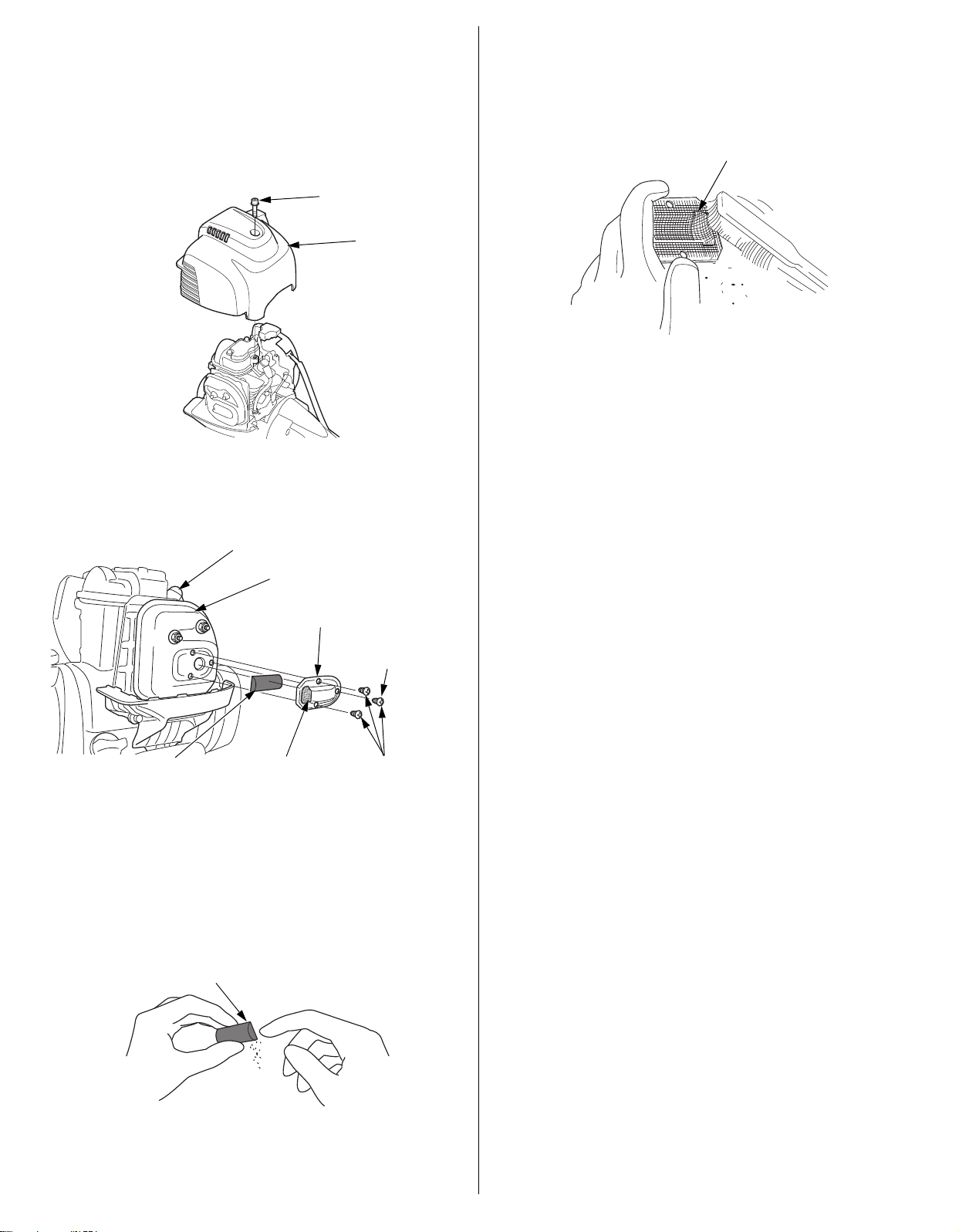
The spark arrester must be serviced every 100 hours to keep it
functioning as designed.
If the engine has been running, the muffler will be hot. Allow it to
cool before servicing the spark arrester.
Spark Arrester Removal
1. Loosen the 5 mm socket bolt, then remove the top cover.
2. Remove the 4×6 mm self-tapping screws from the spark
arrester, and remove the spark arrester and exhaust filter
(UMC435 only) from the muffler.
Spark Arrester Cleaning & Inspection
1. Use a brush to remove carbon deposits from the spark arrester
screen. Be careful to avoid damaging the screen.
The spark arrester must be free of breaks and holes. Replace
the spark arrester if it is damaged.
2. Install the exhaust filter (UMC435 only) and spark arrester in
the reverse order of disassembly.
When you install the spark arrester, the spark arrester’s outlet
must point the opposite side of the spark plug.
3. Install the top cover, and tighten the 5 mm socket bolt securely.
Exhaust Filter Cleaning & Inspection (UMC435 only)
Pinch the exhaust filter, and strike it lightly with a finger, to remove
carbon deposits. Be careful not to strike it too hard. The exhaust
filter must be free of breaks and holes. If it is damaged or fouled
excessively, replaced it.
18
Page 19
HELPFUL TIPS & SUGGESTIONS
ENGINE OIL FILLER CAP
FUEL FILLER NECK
FUEL TANK CAP
FUEL RETURN TUBE
(TRANSPARENT
TUBE)
FUEL TANK CAP
PRIMING PUMP
Short Term Storage (30–90 days)
STORING YOUR POWERHEAD
Storage Preparation
Proper storage preparation is essential for keeping your powerhead
trouble-free and looking good. The following steps will help to keep
rust and corrosion from impairing your powerhead’s function and
appearance, and will make the engine easier to start when you use
it again.
Cleaning
If the engine has been running, allow it to cool for at least half an hour
before cleaning. Clean all exterior surfaces, touch up any damaged
paint, and coat other areas that may rust with a light film of oil.
Using a garden hose or pressure washing equipment can force
water into the air cleaner or muffler opening. Water in the air
cleaner will soak the air filter, and water that passes through the
air filter or muffler can enter the cylinder, causing damage.
Fuel
Depending on the region where you operate your equipment, fuel
formulations may deteriorate and oxidize rapidly. Fuel deterioration
and oxidation can occur in as little as 30 days and may cause
damage to the carburetor and/or fuel system. Please check with
your servicing dealer for local storage recommendations.
Adding a Gasoline Stabilizer to Extend Fuel Storage Life
When adding a gasoline stabilizer, fill the fuel tank with fresh
gasoline. If only partially filled, air in the tank will promote fuel
deterioration during storage. If you keep a container of gasoline for
refueling, be sure that it contains only fresh gasoline.
1. Add gasoline stabilizer following the manufacturer’s
instructions.
2. After adding a gasoline stabilizer, run the engine outdoors for
10 minutes to be sure that treated gasoline has replaced the
untreated gasoline in the carburetor.
3. Stop the engine.
Long Term or Seasonal Storage (greater than 90 days)
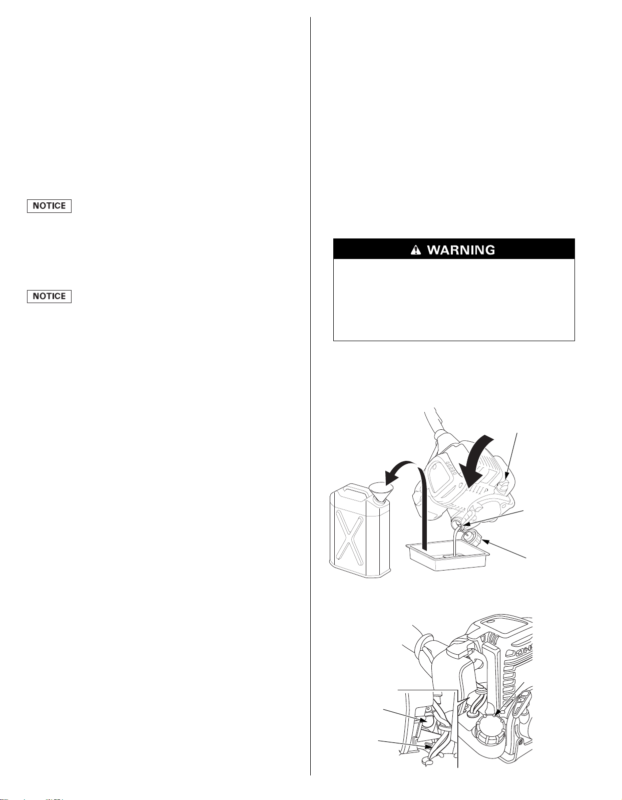
Draining the Fuel Tank and Carburetor
Gasoline is highly flammable and explosive, and you
can be burned or seriously injured when refueling.
• Stop the engine and let cool before refueling.
• Keep heat, sparks, and flame away.
• Refuel only outdoors.
• Wipe up spills immediately.
1. Make sure the engine oil filler cap is tightened securely.
Gasoline will oxidize and deteriorate in storage. Deteriorated
gasoline will cause hard starting, and it leaves gum deposits that
clog the fuel system. If the gasoline in your powerhead deteriorates
during storage, you may need to have the carburetor and other fuel
system components serviced or replaced.
The length of time that gasoline can be left in your fuel tank and
carburetor without causing functional problems will vary with such
factors as gasoline blend, your storage temperatures, and whether
the fuel tank is partially or completely filled. The air in a partially
filled fuel tank promotes fuel deterioration. Very warm storage
temperatures accelerate fuel deterioration. Fuel deterioration
problems may occur within a few months, or even less if the
gasoline was not fresh when you filled the fuel tank.
Fuel system damage or engine performance problems resulting
from neglected storage preparation are not covered under the
Distributor’s Limited Warranty.
You can extend fuel storage life by adding a gasoline stabilizer that
is formulated for that purpose, or you can avoid fuel deterioration
problems by draining the fuel tank and carburetor.
2. Remove the fuel tank cap and drain the fuel into an approved
gasoline container by tipping the powerhead toward the fuel
filler neck.
3. Press the priming pump several times until all fuel left in the fuel
return tube is returned into the fuel tank.
19
Page 20
4. Tip the powerhead toward the fuel filler neck again to drain the
CARRYING HARNESS
MAIN PIPE
fuel.
5. After all fuel has drained, reinstall the fuel tank cap securely.
Engine Oil
TRANSPORTING
If the engine has been running, allow it to cool for at least 15
minutes before loading the powerhead on the transport vehicle. A
hot engine and exhaust system can burn you and can ignite some
materials.
1. Change the engine oil (see page 14).
2. Clean the air cleaner (see page 15).
3. Loosen the 5 mm socket bolt, then remove the top cover (see
page 16).
4. Remove the spark plug (see page 16).
5. Apply a couple of drops of clean engine oil into the cylinder.
6. Install the top cover temporarily.
7. Pull the starter grip several times to distribute the oil in the
cylinder.
8. Remove the top cover, then reinstall the spark plug.
9. Install the top cover, and tighten the 5 mm socket bolt securely.
10.Pull the starter grip slowly until resistance is felt.
11.Move the choke lever to the CLOSED position (see page 5).
12.Cover the powerhead and store in a dry, dust-free area.
Storage Precautions
Always turn the engine switch to the OFF position. Make sure the
fuel cap is securely tightened.
Carrying the powerhead by hand:
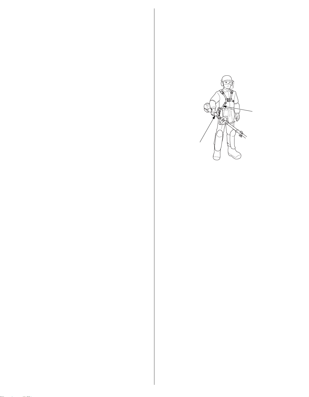
Attach it to the carrying harness or hold the main pipe to carry it
with good balance.
Transporting the powerhead by vehicle:
Secure the powerhead. Make sure it will not move or fall down.
If your powerhead will be stored with gasoline in the fuel tank and
carburetor, it is important to reduce the hazard of gasoline vapor
ignition. Select a well ventilated storage area away from any
appliance that operates with a flame, such as a furnace, water
heater, or clothes dryer. Also avoid any area with a
spark-producing electric motor, or where power tools are operated.
If possible, avoid storage areas with high humidity, because that
promotes rust and corrosion.
Keep the powerhead level in storage. Tilting can cause fuel or oil
leakage.
With the engine and exhaust system cool, cover the powerhead to
keep out dust. A hot engine and exhaust system can ignite or melt
some materials. Do not use sheet plastic as a dust cover. A
nonporous cover will trap moisture around the powerhead,
promoting rust and corrosion.
Removal from Storage
Check your powerhead as described in the BEFORE OPERATION
CHECKS section of this manual (see page 6).
If the fuel was drained during storage preparation, fill the tank with
fresh gasoline. If you keep a container of gasoline for refueling, be
sure it contains only fresh gasoline. Gasoline oxidizes and
deteriorates over time, causing hard starting.
If the cylinder was coated with oil during storage preparation, the
engine will smoke briefly at startup. This is normal.
20
Page 21
TAKING CARE OF UNEXPECTED PROBLEMS
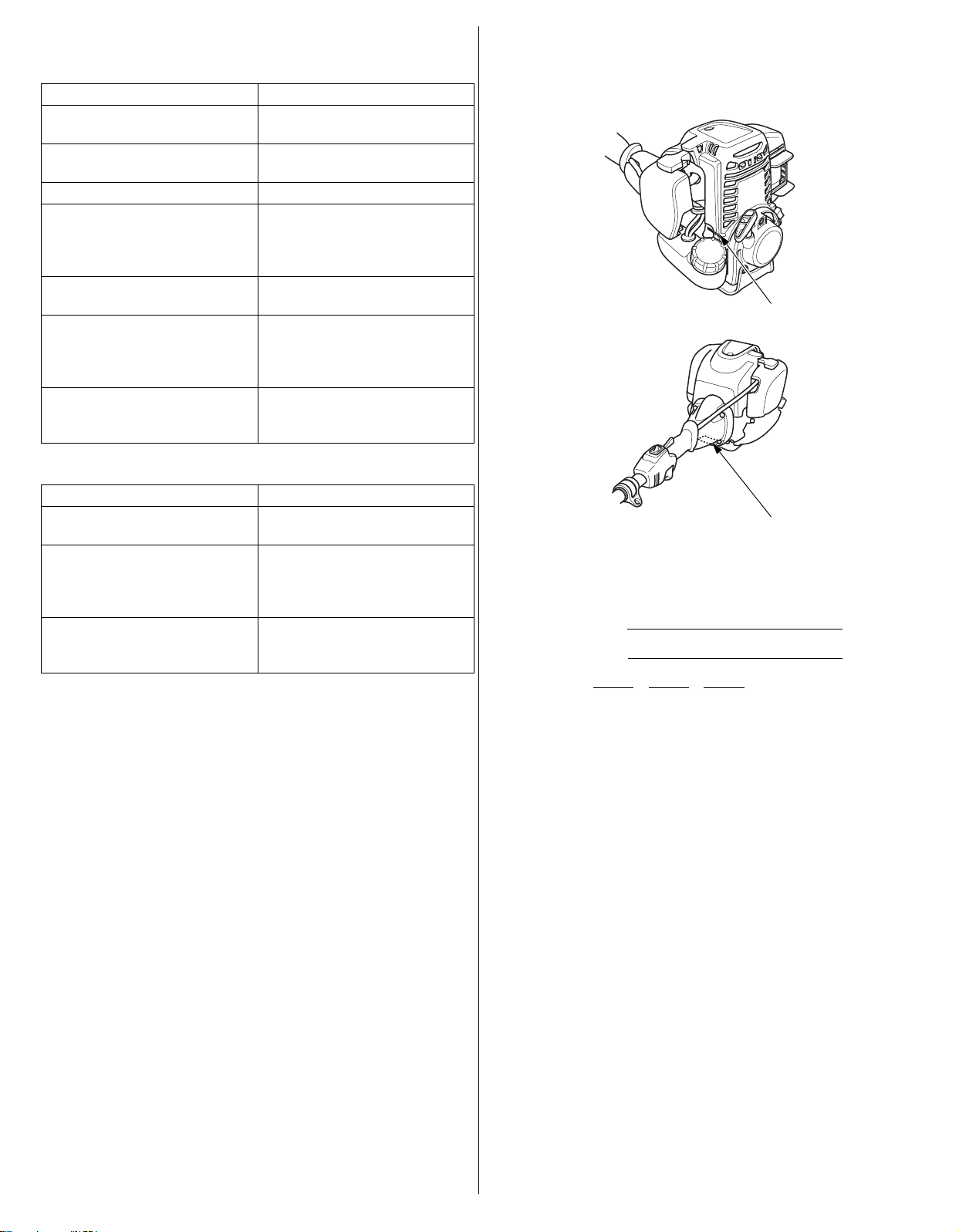
ENGINE SERIAL NUMBER
FRAME SERIAL NUMBER
TECHNICAL & CONSUMER INFORMATION
ENGINE WILL NOT START
Possible Cause Correction
Choke open. Move lever to CLOSED position
unless the engine is warm.
Engine switch OFF. Turn engine switch to ON
position.
Out of fuel. Refuel (p. 13).
Bad fuel; powerhead stored
without treating or draining
gasoline, or refueled with bad
gasoline.
Spark plug faulty, fouled, or
improperly gapped.
Spark plug wet with fuel
(flooded engine).
Fuel filter restricted, carburetor
malfunction, ignition
malfunction, valves stuck, etc.
ENGINE LACKS POWER
Possible Cause Correction
Filter element restricted. Clean or replace filter element
Bad fuel; powerhead stored
without treating or draining
gasoline, or refueled with bad
gasoline.
Fuel filter restricted, carburetor
malfunction, ignition
malfunction, valves stuck, etc.
Drain fuel tank and carburetor
(p. 19). Refuel with fresh
gasoline (p. 13).
Gap or replace spark plug
(p. 16).
Allow the spark plug to dry.
After drying, install the spark
plug and start the engine
(p. 10).
Take powerhead to your
servicing dealer, or refer to shop
manual.
(p. 15).
Drain fuel tank and carburetor
(p. 19). Refuel with fresh
gasoline (P. 13).
Take powerhead to your
servicing dealer, or refer to shop
manual.
TECHNICAL INFORMATION
Serial Number Location
Record the engine and frame serial numbers in the spaces below.
You will need these serial numbers when ordering parts and when
making technical or warranty inquiries.
Engine serial number:
Frame serial number:
Date Purchased: / /
21
Page 22

Carburetor Modifications for High Altitude Operation
At high altitude, the standard carburetor air-fuel mixture will be too
rich. Performance will decrease, and fuel consumption will
increase. A very rich mixture will also foul the spark plug and cause
hard starting. Operation at an altitude that differs from that at
which this engine was certified, for extended periods of time, may
increase emissions.
High altitude performance can be improved by specific
modifications to the carburetor. If you always operate your
powerhead at altitudes above 5,000 feet (1,500 meters), have
your servicing dealer perform this carburetor modification. This
engine, when operated at high altitude with the carburetor
modifications for high altitude use, will meet each emission
standard throughout its useful life.
Even with carburetor modification, engine horsepower will
decrease about 3.5% for each 1,000-foot (300-meter) increase in
altitude. The effect of altitude on horsepower will be greater than
this if no carburetor modification is made.
When the carburetor has been modified for high altitude operation,
the air-fuel mixture will be too lean for low altitude use. Operation
at altitudes below 5,000 feet (1,500 meters) with a modified
carburetor may cause the engine to overheat and result in serious
engine damage. For use at low altitudes, have your servicing dealer
return the carburetor to original factory specifications.
Emission Control System Information
Source of Emissions
The combustion process produces carbon monoxide, oxides of
nitrogen, and hydrocarbons. Control of hydrocarbons and oxides of
nitrogen is very important because, under certain conditions, they
react to form photochemical smog when subjected to sunlight.
Carbon monoxide does not react in the same way, but it is toxic.
Honda utilizes lean carburetor settings and other systems to reduce
the emissions of carbon monoxide, oxides of nitrogen, and
hydrocarbons.
The U.S. and California Clean Air Acts
EPA and California regulations require all manufacturers to furnish
written instructions describing the operation and maintenance of
emission control systems.
The following instructions and procedures must be followed in
order to keep the Honda engine emissions within the emission
standards.
Tampering and Altering
Tampering is a violation of Federal and California law.
Tampering with or altering the emission control system may
increase emissions beyond the legal limit. Among those acts that
constitute tampering are:
• Removal or alteration of any part of the intake, fuel, or exhaust
systems.
• Altering or defeating the governor linkage or speed-adjusting
mechanism to cause the engine to operate outside its design
parameters.
Problems That May Affect Emissions
If you are aware of any of the following symptoms, have your
engine inspected and repaired by your servicing dealer.
• Hard starting or stalling after starting.
• Rough idle.
• Misfiring or backfiring under load.
• Afterburning (backfiring).
• Black exhaust smoke or high fuel consumption.
Replacement Parts
The emission control systems on your Honda engine were
designed, built, and certified to conform with EPA, California and
Canadian emission regulations. We recommend the use of Honda
genuine parts whenever you have maintenance done. These
original-design replacement parts are manufactured to the same
standards as the original parts, so you can be confident of their
performance. The use of replacement parts that are not of the
original design and quality may impair the effectiveness of your
emission control system.
A manufacturer of an aftermarket part assumes the responsibility
that the part will not adversely affect emission performance. The
manufacturer or rebuilder of the part must certify that use of the
part will not result in a failure of the engine to comply with
emission regulations.
Maintenance
Follow the maintenance schedule on page 12. Remember that this
schedule is based on the assumption that your machine will be
used for its designed purpose. Sustained high-load or
high-temperature operation, or use in unusually wet or dusty
conditions, will require more frequent service.
Air Index
(Models certified for sale in California)
An Air Index Information hang tag/label is applied to engines
certified to an emission durability time period in accordance with
the requirements of the California Air Resources Board.
The bar graph is intended to provide you, our customer, the ability
to compare the emissions performance of available engines. The
lower the Air Index, the less pollution.
The durability description is intended to provide you with
information relating to the engine’s emission durability period. The
descriptive term indicates the useful life period for the engine’s
emission control system. See your Emission Control System
Warranty for additional information.
Descriptive Term Applicable to Emissions Durability Period
Moderate 50 hours (0–80 cc, inclusive)
125 hours (greater than 80 cc)
Intermediate 125 hours (0–80 cc, inclusive)
250 hours (greater than 80 cc)
Extended 300 hours (0–80 cc, inclusive)
500 hours (greater than 80 cc)
1,000 hours (225 cc and greater)
The Air Index Information hang tag/label must remain on the
powerhead until it is sold. Remove the hang tag before operating
the powerhead.
22
Page 23
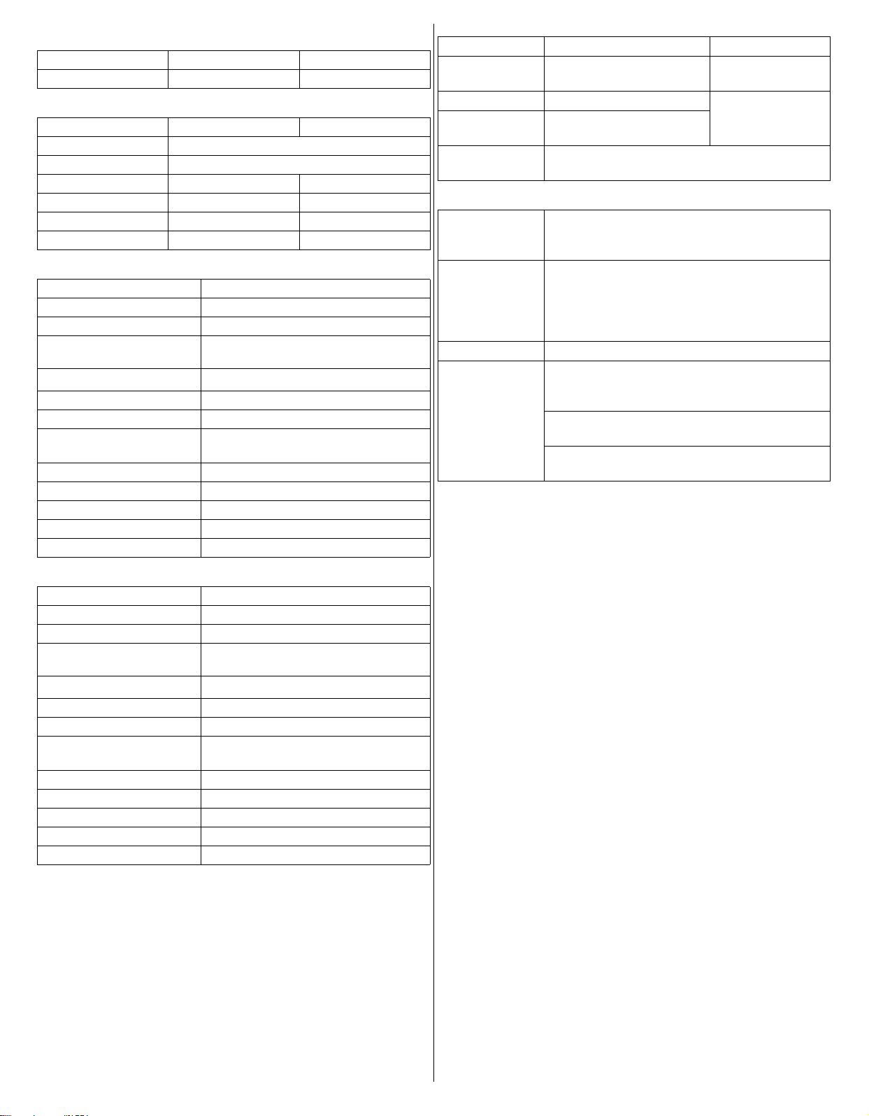
Specifications
MODEL UMC425 UMC435
Description code HAGT HAHT
Frame
MODEL UMC425 UMC435
Handle type Loop
Clutch type Centrifugal clutch
Overall length 44.7 in (1,135 mm) 45.1 in (1,145 mm)
Overall width 12.4 in (315 mm) 12.6 in (320 mm)
Overall height 9.6 in (245 mm) 10.0 in (255 mm)
Dry mass (weight) 11.2 lbs (5.1 kg) 13.2 lbs (6.0 kg)
Engine
MODEL UMC425
Engine model GX25T
Engine description code GCALT
Engine type 4-stroke, overhead cam, single
cylinder
Displacement
1.5 cu-in (25.0 cm
3
)
Bore x Stroke 1.4 × 1.0 in (35.0 × 26.0 mm)
Idle speed 3,100 ± 200 rpm
Maximum no load engine
MIN. 10,000 rpm
speed
Cooling system Forced air
Ignition system Transistor magneto
Engine oil capacity 2.7 oz (0.08 L)
Fuel tank capacity 0.14 US gal (0.53 L)
Spark plug CMR5H (NGK)
Tuneup Specifications
ITEM SPECIFICATION MAINTENANCE
Spark plug gap 0.024–0.028 in
Refer to page: 16
(0.6–0.7 mm)
Idle speed 3,100±200 rpm See your
Valve clearance
(cold)
Other
IN: 0.08±0.02 mm
EX: 0.11±0.02 mm
No other adjustments needed.
authorized Honda
dealer
specifications
Quick Reference Information
Fuel Regular unleaded gasoline with an ethanol
content of no more than 10% and a pump
octane rating of 86 or higher (see page 13).
Engine oil SAE 10W-30, API SJ or later, for general use.
Include capacities:
UMC425: 2.7 oz (0.08 L)
UMC435: 3.3 oz (0.10 L)
Refer to page 13.
Spark plug CMR5H (NGK)
Maintenance Before each use:
• Check engine oil level. Refer to page 13.
• Check air filter. Refer to page 15.
First 10 hours:
Change engine oil. Refer to page 14.
Subsequent:
Refer to the maintenance schedule on page 12.
Engine
MODEL UMC435
Engine model GX35T
Engine description code GCAMT
Engine type 4-stroke, overhead cam, single
cylinder
Displacement
2.18 cu-in (35.8 cm
3
)
Bore x Stroke 1.5 × 1.2 in (39.0 × 30.0 mm)
Idle speed 3,100 ± 200 rpm
Maximum no load engine
MIN. 10,000 rpm
speed
Cooling system Forced air
Ignition system Transistor magneto
Engine oil capacity 3.3 oz (0.10 L)
Fuel tank capacity 0.17 US gal (0.63 L)
Spark plug CMR5H (NGK)
Specifications may vary according to the types, and are subject to
change without notice.
23
Page 24

CONSUMER INFORMATION
Customer Service Information
Dealer Locator Information
To find an authorized Honda Servicing Dealer anywhere in the
United States, visit our web site: http://
powerequipment.honda.com/dealer-locator
Honda Publications
Shop Manual
This manual covers complete maintenance and overhaul
procedures.
It is intended to be used by a skilled technician.
Available through your Honda dealer or visit
http://powerequipment.honda.com/support/shop-manuals
Parts Catalog
This manual provides complete, illustrated parts lists. Available
through your Honda dealer.
Accessories Catalog
Your authorized Honda power equipment dealer offers a selection
of accessories (optional equipment) to make your Powerhead even
more useful.
Visit http://powerequipment.honda.com/trimmers/accessories
and click on see all powerhead accessories to see the entire catalog
of accessories.
Honda Power Equipment dealership personnel are trained
professionals. They should be able to answer any question you may
have. If you encounter a problem that your dealer does not solve to
your satisfaction, please discuss it with the dealership’s
management. The Service Manager or General Manager can help.
Almost all problems are solved in this way.
If you are dissatisfied with the decision made by the dealership's
management, contact the Honda Power Equipment Customer
Relations Office. You can write:
American Honda Motor Co,. Inc.
Power Equipment Division
Customer Relations Office
4900 Marconi Drive
Alpharetta, Georgia 30005 – 8847
Or telephone: (770) 497 – 6400 MF 8:30 am to 7:00 pm ET
When you write or call, please give us this information:
• Model and serial numbers (see page 21)
• Name of the dealer who sold the Powerhead to you
• Name and address of the dealer who services your Powerhead
• Date of purchase
• Your name, address, and telephone number
• A detailed description of the problem
24
 Loading...