

Page 1
Page 2

Page 3
INTRODUCTION
Thank you for purchasing an
This
manual covers
the
assembly, operation and maintenance of
attachments:
0
0
0
0
0
"
"
For your convenience,
NOTE:
The information
information available
the
reserves
right
with
Dozer Blade
Two
Stage Snowblower
Rotary Broom
a
parts
in
at
to
make changes
incurring any obligation.
No
part
Pay
of
special
this
publication may be reproduced without
attention
Indicates
are
not followed.
to
that
the
HTA
attachment for your Honda Tractor.
the
Quick
guide
this
time
Hitch
is
System
also included in
publication
of
printing.
at
any
statements preceded by
serious injury
or
is
American
time
death
the
following
this
publication.
based
on
the
latest
Honda Motor
product
Co.,
without notice and without
written
the
following symbols:
WILL
permission.
result
instructions
HTA
Inc.
Indicates
result if instructions
Indicates
are
:
Indicates
instructions
NOTE
:
Gives helpful information.
HTA attachments
not
are
a
strong possibility
are
a
possibility
not followed.
that
minor injury can result if instructions
that
followed.
that
are
equipment
not followed.
or
property damage can result
designed to give safe and dependable service if assembled and
operated according to instructions.
If
a
problem should
arise,
or if you have any questions about your attachment(s1,
consult an authorized Honda compact Tractor dealer.
OM
0179
1
serious injury
or
death can
if
Page 4
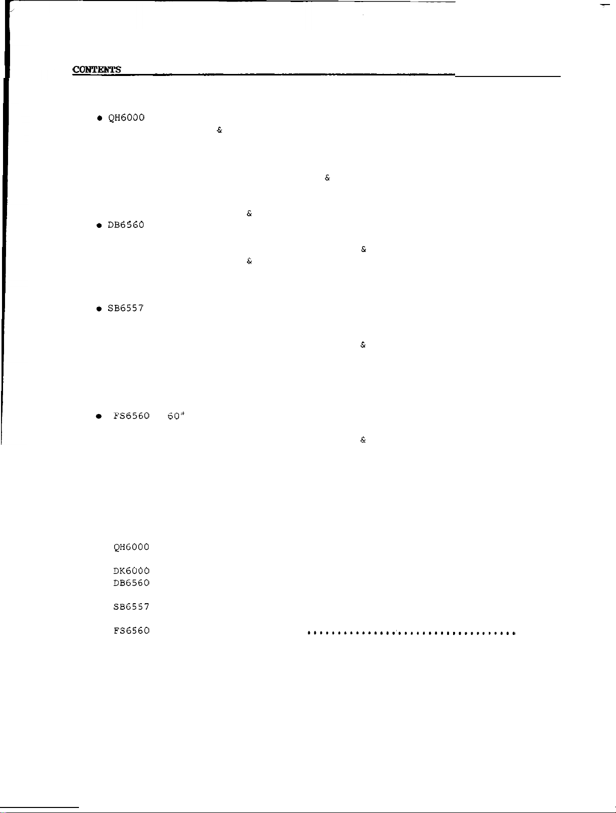
PAGE
INTRODUCTION
SAFETY PRECAUTIONS
PARTS GUIDE
Decals
TORQUE SPECIFICATION TABLE
WARRANTY SERVICE
............................................................
......................................................
-
QUICK
-
60" FRONT DOZER
.
57" TWO
.
.
Two
Subframe with Quick Hitch System
.
Drive
.
Blade Angling Cylinder
60" Front
.
57" Two Stage Snowblower
.
60
ATTACH SUBFRAME WITH
SAFETY
OPERATION
ASSEMBLY
DISMOUNTING
SAFETY DECALS
OPERATION
MAINTENANCE
ASSEMBLY
STAGE SNOWBLOWER
SAFETY DECALS
OPERATION
MAINTENANCE
ASSEMBLY
SAFETY DECALS
OPERATION
MAINTENANCE
ASSEMBLY
DISMOUNTING
Spool Valve
Kit
Components
"
Front Rotary Broom
Components
............................................................
.....................................
QUICK
INSTRUCTIONAL DECALS
HITCH SYSTEM
...........................
...............................................
.
Step 1: Subframe assembly
Step 2: Mid PTO kit
Step 3: Valve
Step 4: Tractor
Step
5:
Attaching frame
REMOUNTING
BLADE
................................
installation
hose
preparation
installation
....................
.............
..................
to
tractor
...........................................
.
Operating
-
Step
Step
Step 3:
DISMOUNTING
1:
2:
controls
adjustment
.............
...............................
Blade
Hydraulic angling installation
Blade
assembly
installation
.......................
...................
...........................................
.
Preparing for
Operating
Snow
removal
snow
controls
methods
removal
adjustments
..................
........................
.............................................
.
Step
Step 2: Chute
Step 3: Attaching snowblower
BROOM
1:
Snowblower assembly
and
hydraulic
..................
rotation
to
quick hitch
...........................................
.
Operating
Applications
.
General
.
Brush
.
Step
Step
Step 3: Optional dolly wheel
1:
2:
controls
adjustments
................................
...................................
replacement
Broom
Broom
preparation
installation
.........................
....................
...................
installation
.............................................
..........................................
.........................
................................................
...................................
Dozer
Blade
....................................
.................................
..............................................
..............................................
...............................................
(inside back
............
...........
.......
............
.........
............
....
cover)
..
1
3
6
7
8
9
10
11
12
15
16
17
18
19
20
21
22
23
24
25
26
27
28
29
31
32
33
34
35
36
37
39
40
41
42
46
49
50
52
54
60
63
69
71
OM
0179
2
Page 5
A
CAREFUL OPERATOR IS THE BEST
-
OPERATOR
MOST ACCIDENTS CAN
BY OBSERVING CERTAIN PRECAUTIONS
BE
AVOIDED
-
READ
AND TAKE THE FOLLOWING PRECAUTIONS
BEFORE
HELP PREVENT ACCIDENTS
SHOULD BE OPERATED ONLY BY
OPERATING THESE A!WACEMENTS
-
RESPONSIBLE
INSTRUCTED
To
EQUIPMENT
THOSE
To
WHO
DO SO-
THE ATTACHMENT
1.
Read
this
manual carefully
yourself
as
the
Working
with
tractor operator's manual.
with
can lead to accidents.
with
use
stop
shields
all
of
proper
how
2.
familiar
to
the
controls quickly.
Keep
all
tighten
the
equipment
unfamiliar equipment
the controls and
the
equipment. Know
the
unit and disengage
in
place
mounting hardware.
to
acquaint
as
Be
thoroughly
and properly
well
SAFETY PRECAUTIONS
2.
Clothing worn by
the
operator should
be fairly tight and belted. Loose
clothing can easily become caught
on moving
3.
Prolonged exposure to loud noise can
parts
cause impairment
Wear
a
suitable hearing protective
device such
or controls.
or
loss
of hearing.
as
earmuffs or earplugs
to protect against objectionable or
uncomfortable noises.
OPERATING THE ATTACHMENT(S)
To
PRECAUTIONS SHOULD
OPERATING EACH
1.
Never allow anyone to
OF
BE
TAKEN BEFORE
THESE ATTACHMENTS.
ride
attachment.
on
the
3.
Periodically
for
service
of
4.
Replace
wear
parts
wear
and
inspect
replace
all
with
moving
authorized
if an excessive amount
is
present.
all
missing, illegible, or
damaged safety and warning decals.
See
list
of
decals
at
the
your
5.
Do
not modify or
or any of
alter
its
components , or any
equipment
equipment function without first
consulting an authorized Honda
compact tractor
Keep
safety decals clean
dealer.
of
grime.
GENERAL PREPARATION
1.
Be
sure
before starting
the
PTO
is
the
in
OFF
engine.
parts
end of
dirt and
position
2.
Clear
the
area
of people and debris
before commencing operation.
3.
Never allow children to operate
equipment. Never allow
adults
operate equipment without proper
instruction.
4.
Always keep
the
attachment discharge
directed away from people and objects
which
Never
could be struck
allow
anyone in front
by
debris.
Never leave attachment in raised
position.
7.
Never
operate
the
attachment without
good visibility and lighting.
8.
Never clean or adjust PTO
equipment
with
the
tractor engine
running.
of
unit.
-
driven
to
OM
0179
3
Page 6

SAFETY
PRECAUTIONS
When operating PTO-driven equipment,
shut
off
the
always
for
the
PTO to stop turning before
getting off
unplugging
the
the
engine and
tractor, before
housing or discharge chute and
before making any
or
inspections.
10.
Take
all
leaving
Disengage
possible precautions when
the
repairs,
adjustments
vehicle unattended.
the
PTO, lower
attachment, shift into neutral,
the
parking brake, stop
the
and remove
11.
Disengage power
transporting
key.
to
attachment when
or
when not in use.
12. The operator must never
13.
tractor
Exercise
while
it
is
extreme caution when
the
get
in motion.
operating on or crossing gravel
drives, walks or roads. Stay
for
the
hidden hazards of traffic.
14.
Do not put hands or feet near rotating
parts.
at
15.
Do not use hands or feet
all
Keep
times.
clear
of discharge opening
to
spout.
16.
Keep a careful
could enter
watch
the
for debris
blower
operating.
17. Never operate
guards, shields and
the
attachment without
other
protective devices in
wait
the
engine
off
alert
unplug
that
while
safety
set
the
19.
Use
care
when backing
up.
20. After striking a foreign object, stop
the
engine,
to stop,
attachment for
the
damage before restarting and
operating
the
21. If
start
sweeper
to vibrate abnormally, stop
engine immediately and check for
cause. Vibration
wait
the
for
all
damage
attachment.
or snowblower should
is
generally
movements
and
repair
the
the
the
warning of trouble.
22.
Do not
slopes.
clear
snow
across
the
face of
Exercise extreme caution when
changing direction on slopes. Do not
attempt
to
clear
steep
slopes.
23 Escaping
the
pressure can penetrate
skin causing
serious injury.
Do
not use your hands to check
for leaks.
cardboard or
for
leaks.
Use
paper
a
piece
to
search
of
Stop engine and relieve pressure
by moving valve handles back
and forth before connecting or
disconnecting lines.
Tighten
all
connections before
starting engine or pressurizing
lines.
If
any fluid
skin,
the
it
fluid
within
familiar
a
with
is
injected into
the
may result in gangrene if
is
not surgically removed
few hours by
this
form of injury.
a
doctor
a
18.
Never operate machine
transport speeds on
ace.
surf
OM
at
a
slippery
high
4
Page 7
THE
TRACTOR
1.
Read
the
Operator's
Manual carefully
before using tractor. Lack of
operating knowledge can lead
accidents.
to
11.
Keep
Use
for
the
11.
of
tire
better
tractor
traction and stability
recommended. See
recommended weighing.
in
gear
chains and
Tractor
SAFETY
when going
wheel
Manual for
PRECAUTIONS
weights
is
2.
Do
not
to ride
permit
on
anyone but
the
tractor.
the
There
operator
is
no compatible
12. Always drive
operating
crossing ditches, or when turning.
OPERATING THE TRACTOR MAINTENANCE
start
beside
tractor
the
engine while standing
the
tractor. Always
seat
while
starting
1.
Provide adequate blocking before
sit
on
the
the
engine raised position.
working under an attachment when in
or operating controls.
2.
Make certain
2.
Never run
closed building without adequate
ventilation
are
very dangerous.
Never
fuel tank
Use
a
emblem and
lamps
roads, day or night,
by
law
the
tractor
as
the
engine in
exhaust fumes
an open flame near
or
battery. maintenance when
slow moving vehicle
the
flasher warning
when traveling on
in your
unless
state.
prohibited
the
(SMV)
public
a
stopped before cleaning, repairing
or
inspecting.
3.
Do
not run engine indoors.
4.
Do
not
is
running, or when
is
raised.
with
STORAGE
attempt
the
tractor
at
safety, especially
over rough ground,
all
to
the
moving
repair
parts
or
perform
tractor engine
the
attachment
speeds
have
6.
Make
sure
the
when using PTO
always
replace
7. Always bring
stop and shut off
getting off
8.
Never park
PTO shield
-
driven equipment and
PTO shield if damaged.
the
tractor to a complete
the
the
tractor.
the
tractor on
is
engine before
incline.
Use
9.
care
when operating on
grades to maintain proper stability.
OM
0179
installed
a
steep
steep
5
Page 8
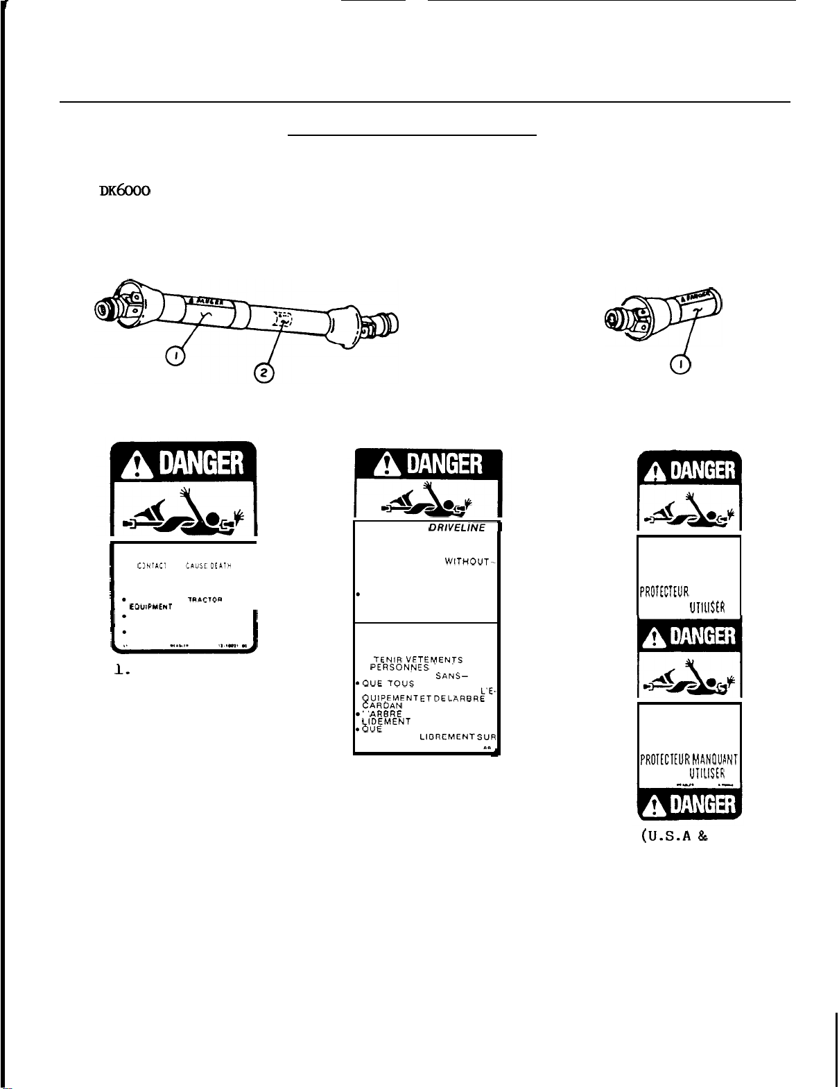
SUBFRAME
-
SAFETY
DECALS
(drive
ROTATING DRIVELINE
KEEP AWAY!
DO
NOT
OPERATE
ALL DRIVLLINE. TRACIOR AND
DRIVELINES SECURELV
ATTACHED AT BOTH ENDS
DRIVELINE SHIELDS THAT TURN
FREELY ON DRIVELINE
(U.S.A.
kit)
WITHOUT
only)
-
I
REPLACE
IMMEDIATELY
ROTATING DRIVELibE-
CONTACT CAN CAUSE DEATH
KEEP PEOPLE AND CLOTHING
WELL CLEAR
DO
NOT OPERATE WITHOUT-
*ALL DRIVELINE. TRACTOR
AND EQUIPMENT SHIELDS
IN PLACE
DRIVELINES SECURELY
ATTACHED AT BOTH ENDS
*DRIVELINE SHIELDS THAT
TURN FREELY
TRANSMISSION ROTATIVE
A CARDAN
TOUT CONTACT PEUT
CAUSER LA MORT
NE PAS OPERER SANS-
TEURSDU TRACTEUR.DE
L ARBRE A CARDAN FIXE
TOURNENT
L'ARBRE A CARDAN
IF
ON
DRIVELINE
A
CHAQUE BOUT
DAMAGED
SO
SHIELD
DO
MISSING
NOT OPERATE
MANOUANT
Nt
PAS
SHIELD
DO
MISSING
NOT OPERATE
OM
0179
1.
(CANADA
6
only)
2.
Visible
shield
NE
PAS
CANADA)
only
is
missing.
if
Page 9

OPERATION
RAISING
(Dozer
Attachments
the
valve handle: Float position
pushing
Blade, Snowblower, Rotary
can
be
raised or lowered using
right hand (farthest from operator)
is
obtained by
the
right handle fully forward.
broom)
OPERATION
-
AUXILIARY
This
either
and 'on
rotation on
VALVE
valve (closest to operator)
for power angling on
the
dozer blade or for
the
snowblower. If motion
the
rotary broom
the
is
used
chute
contrary to attachment operation instructions,
simply
switch
attachment
male
quick coupler
locations.
MAINTENANCE SERVICE
Never store
the
STORAGE
tractor
with
fuel in
the
fuel tank inside a building where open
flame or sparks
engine
to
cool before storing in any
present. Allow
the
are
enclosure.
LUBRICATION
1
.
DRIVELINE:
every
shaft
with
8
apart
grease every
Grease
each
u-joint fitting
hours of operation.
and coat sliding surfaces
24
hours
Slide
of
operation.
drive
is
2.
SUBFRAME:
Grease
all
fittings on lift
and on subframe attaching points every
hours of operation.
STORAGE
1
.
2.
3.
4.
5.
01
Clean
Repaint
When
parts.
Lubricate
Store
a
dry
79
the
subframe thoroughly.
all
the
the
place.
parts
subframe
the
subframe and attachment(s) in
from
is
subframe
which
dry,
as
paint
oil
instructed
all
has
moving
above.
8
worn.
7
Page 10
-
ASSEMBLY
NOTICE
through completely and familiarize yourself
assembly,
STEP
a)
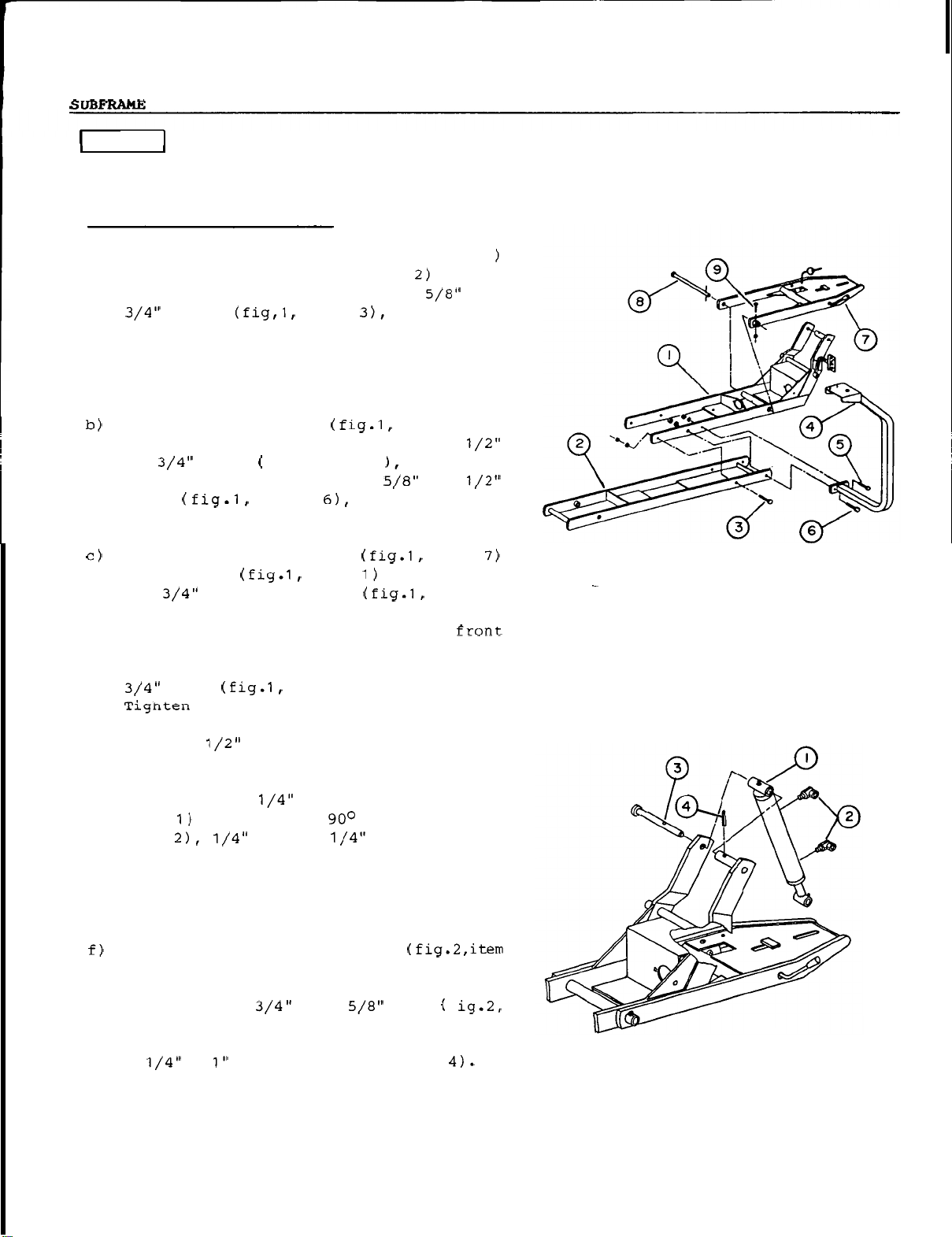
Assemble front section (fig.
and
subframe together, using
Before beginning assembly
1
:
torque
SUBFRAME
rear
all
bolts according to
ASSEMBLY
section (fig.
1,
item
three
of
this
the
1
,
i
tem
the
x
item
and nuts. Tighten securely.
NOTE:
with
Rear
section of subframe must be installed
reinforcement
Attach
right hand
x
1
and
bolt (fig.1,
nut.
Attach
to
the
through
hitch
section. Lock
hand side of subframe using
valve support (fig.1,
nut
in front hole and
Tighten securely.
male
subframe (fig.1,
x
the
and through
bolt
side
plates
of
fig.
on bottom side.
subframe using one 1/2"
1
,
item
item
quick
hitch
item
11
13/16" pin (fig.1,
left hand side of
the
the
pin in
item
9)
5
a
lockwasher and
subframe front
place
and nylon nut.
item
by inserting
4) 'to
lockwasher
x
2 1/2"
item
item
the
quick
on right
a
5/16
"
x
subframe,
with
torque
1
1
8)
1
please
all
the
specification table on page 71.
FIGURE
read
parts.
1
the
instructions
After completing
x
d) Install
e)
quick
On
item
hitch
the
2
" x 6 1/4" lift cylinder (fig.2,
install
item
in cylinder
Cylinder base end being 12 o'clock,
base end
and rod end elbow
Install
1
)
between
of subframe.
place
item
is
vertical. Lock
a
OM
0179
elbow
lift cylinder
the
with
3)
making sure
x
3" handle
lever.
two
male
port
at
x
using thread sealant.
approximately
at
12 o'clock.
base
welded tube and side
Attach
a
roll pin (fig.2,
cylinder
x
6
the
the
pin in
grip
elbows (fig.2,
end (fig.2,item
on
10
o'clock
male
place
plate
base
pin
hole in
place
end in
f
the
using
item
pin
8
FIGURE
2
Page 11
into
the
secure
item
quick
the
male
grease fitting
with
hitch
a
the
(make sure
vertical). Lock
1
the
quick
x
right
hitch.
pin (fig.
hand
rod
end (fig.3,
quick
hitch,
is
on front
x
4
right hand
the
pin in
3,
welded
1
side
hole
item
tube
item
making sure
side,
and
pin (fig .3,
of
the
male
in pin
place
in
the
with'
male
1)
is
a
STEP
a)
MID
If you
over
Step
Install
KIT INSTALLATION
do
not require
this
3.
19
section and go directly to
this
item
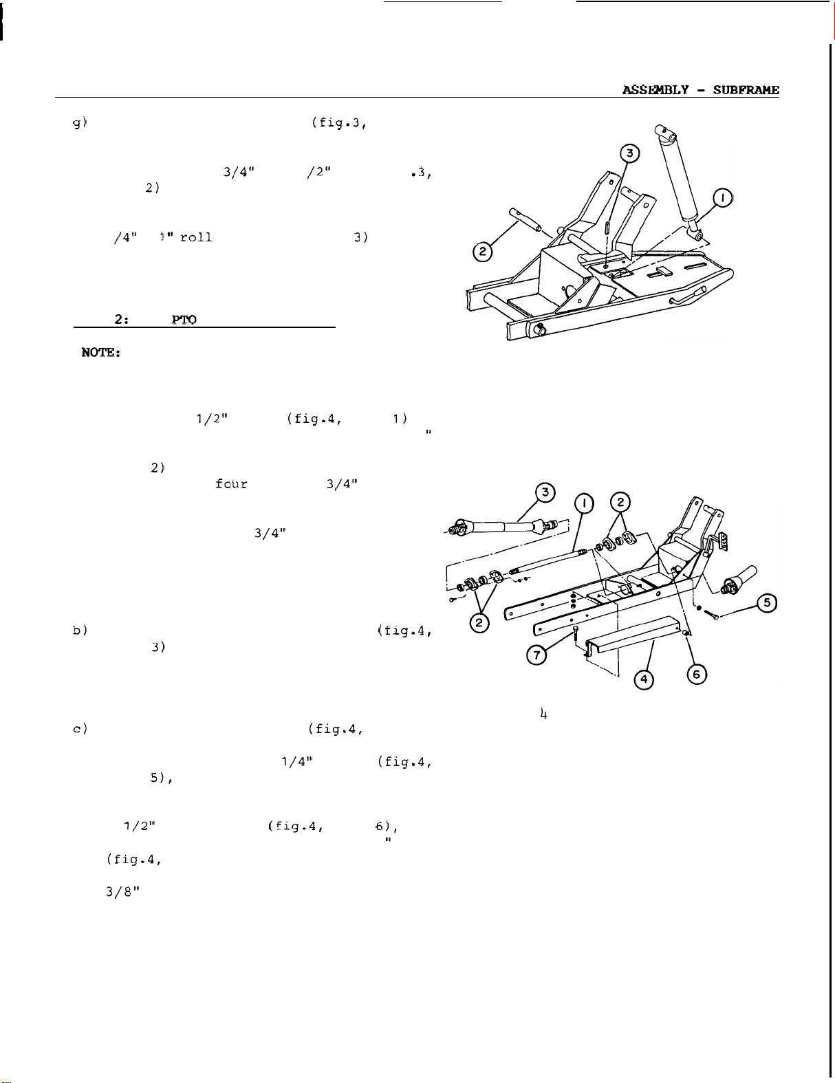
front section of subframe, using
bearings, four bearing retainers (fig.4,
item
plates)
bolts,
two bearings and locking
shaft
rear
place
(placed on
,
and four 5/16
rear
"
side of
x
lockwashers and nuts. Install
collars.
so
that
cross
by turning
3
plate.
Lock
the
the
eccentric
in a clockwise direction (viewed from
rear
of subframe).
Attach
item
sliding back
long end of driveline (fig.4,
to
the
the
shaft
locking
in
subframe by
collar
and pushing driveline yoke over
shaft
until
the
locking
collar
snaps
Install driveline guard (fig.4,
the
on
using one 5/16
item
lockwasher on
bolt
a
through
bracket
front section of the subframe
"
x
in
through
the
the
the
1
front
bolt,
subf
rame
bolt
hole,
placing
then placing
,
then through
item
the
guard.
item
to
7)
the
latwasher
Use
a
5/16
"
to
attach
the
rear
subframe, securing
,
lockwasher
Tighten securely.
kit, skip
in
two
1
cross
the
Adjust
shaft in
collars
on yoke
the
back.
item
4)
a
the
and
x
1
bolt
guard
with
and
a
nut.
FIGURE
FIGURE
3
OM
01
79 9
Page 12

-
3:
ASSEMBLY
VALVE
HOSE
INSTALLATION
Thread
male
ports,
Install
of valve support
three
and nuts. Tighten securely.
Thread both handles on
as
Place two rubber grommets
inside
support, and route
described below through
Install one
base
the
to
Install one
rod end elbow. Route other end
long bend
fitting
the
four
connectors
NPT male
item
using thread sealant.
valve (fig.5,
5/16
"
in figure 1 on page
the
(fig
x
9/16
the
x
2 1/4" bolts, lockwashers
two lower holes
x
end
elbow,
short bend
the
fitting in
in
to
the
the
routing
to
the
the
right hand front port.
x
78
valve and connect
NPT
male
item
"
male
appropriate valve
item
on underside
item
24.
Tighten nuts.
of
the
two 1/4" hoses
the
grommets.
the
the
other
valve, and connect
"
hose in
hand
the
rear
x
7/16
1
and two
connectors
item
the
hose
cylinder
end
with
cylinder
with
port
to
-
the
the
"
FIGURE
5
Place straight end of 62" hose (fig.6,item
the
hole second from
the
of
washer
female quick coupler
ring over threaded portion) using thread
sealant. Route
short bend to
the
Place straight end of
item
bracket.
end, and install female quick coupler(fig.6,
item
threaded portion) using thread sealant.
Route
to
in
OM
0179 10
coupler bracket. Place
on
the
hose end, and install
(with
the
the
valve, connecting to
fitting in
3)
through
Place
the
the
valve, connecting
the
left hand rear port.
the
the
top
a
nylon
the
green
other end
left hand front port.
the
other end
the
64
"
hole
of
washer
I.D.
with
the
to
a
yellow
with
the
on
the
short bend
the
the
top
nylon
the
hose
fitting
a
I
F
I
G
UR
E
6
Page 13
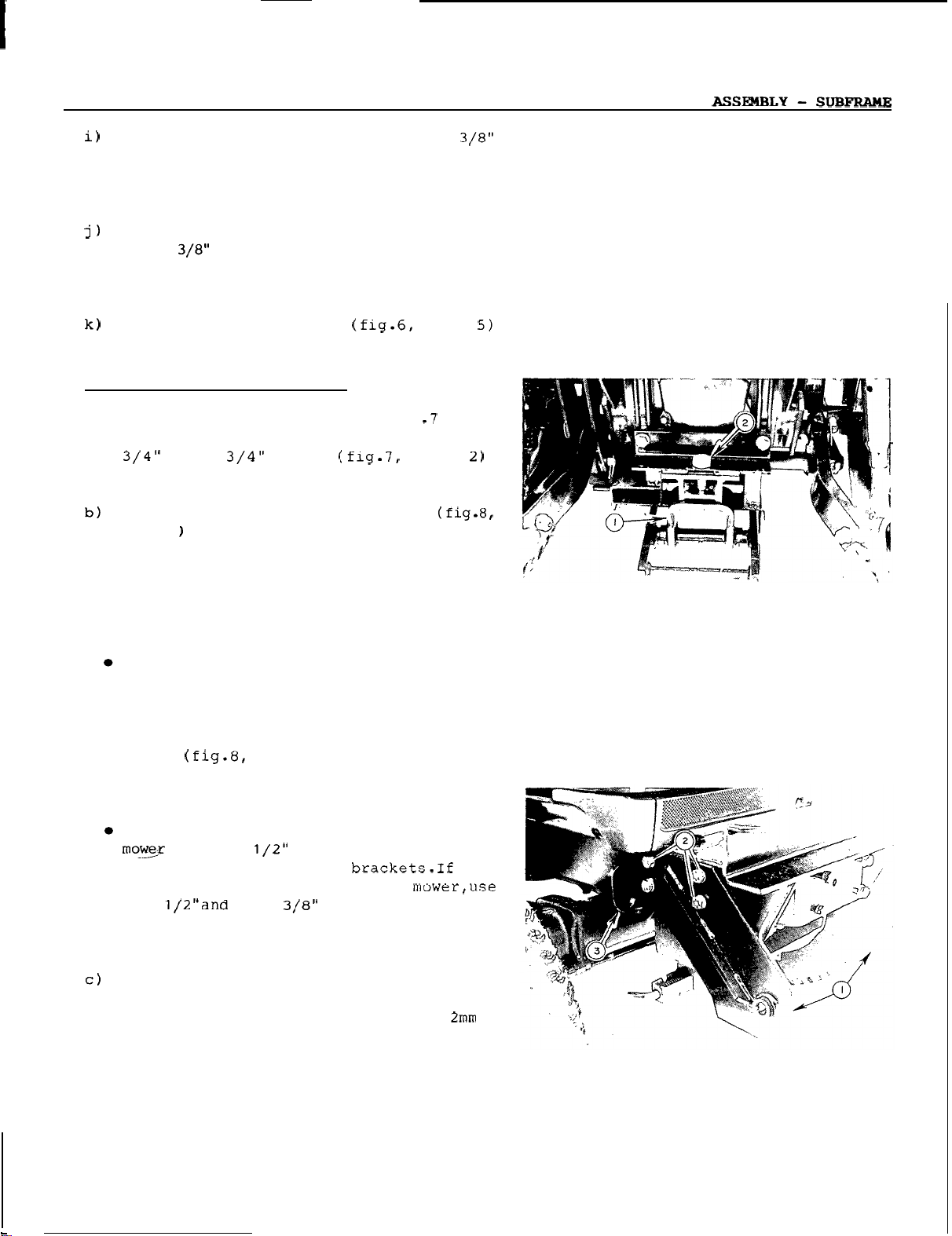
Install
x
30" hose
connect
the
in
a
male
quick coupler on
other
using
end of
thread
hose
right hand inlet
sealant and
to
the
port
on valve.
the
fitting
Install a female quick coupler
of
STEP
a)
the
Connect
the
in
in
small
4:
TRACTOR
Install
1)
under
x
other
left hand outlet
rear
"
end of
cap
hole
of coupler bracket.
PREPARATION
hitch
the
3 3/4"
hose
using thread sealant.
hose
to
port
rings (fig.6,
bracket (fig .7
tractor
bolt
drawbar, using
lockwasher and nut. Tighten lightly.
Install quick
item
1
on
NOTES:
If equipped
mower
If equipped
or
loader
and
mower
If your
tractor
loader and mid mount
existing eight
on
the
engine
time,
bolts
and
placing two quick
the
on
outside of
hitch
the
front brackets (fig.8,
tractor
with
engine
mid mount mower,
bracket remains on
with
the
mower
only,
the
loader subframe
brackets remain on
is
already equipped
mower,
bolts
side
replace
item
from
rails,
with
2)
hitch
the
the
seven
and lockwashers,
front brackets
loader brackets.
Tighten lightly.
If your
,
the
tractor
the
each
and quick
tractor
mower
and quick
has
neither loader nor mowerfuse
the
side between
hitch
is
equipped
shims
hitch
the
bracket.
provided between
shims
engine
at
one end
the
fitting
on valve.
item
,
item
item
side
rails.
the
tractor.
and loader
the
tractor.
with
remove
front brackets
one
side
12mm
with
mid
at
x
50mm
mount
provided
side
rail
the
the
to
a
,
,
FIGURE
a
7
Install one
item
3) on right hand front support bracket,
the
in
hose
lowest
support bracket (fig.8,
rear
hole , using
60mm bolt and lockwasher through support
OM
bracket
0179
and
tractor
frame.
a
1
x
FIGURE
11
8
Page 14
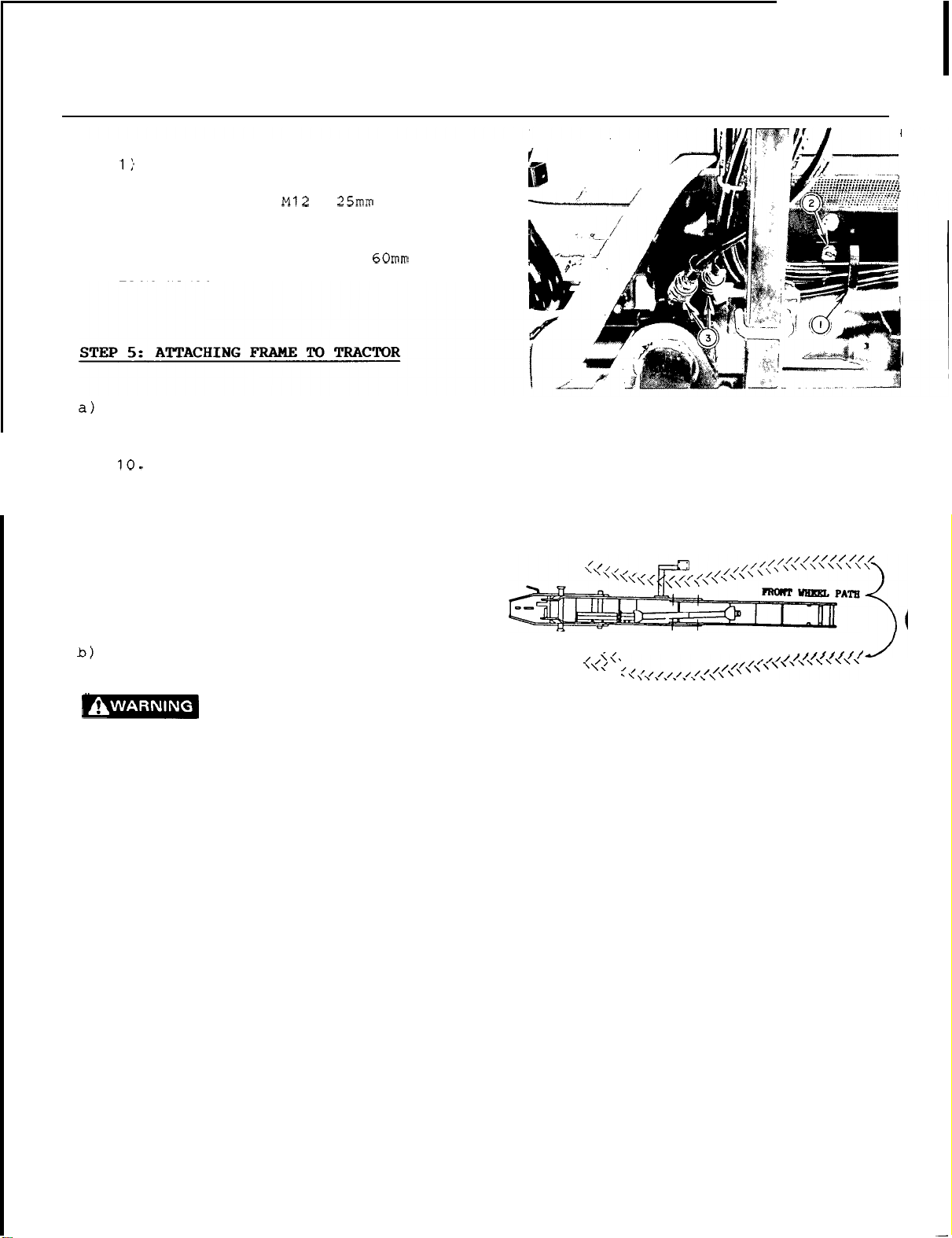
SUBFRAME
-
ASSEMBLY
d) Install second hose bracket (fig.9,
in
the
engine side
lower hole
bracket, using an
item
does not have
has
a
iockwasher.
Carefully
assembly running
over
the
Do
hydraulic hoses.
front right hand wheel. Make sure
section of
front support brackets and
attaching point
The
subframe must be
length in
rear
of
2)
and lockwasher if
a
loader, use an
place
the
valve support
not run
the
the
Place
subframe
is
the
center of
rail,
the
front right attaching
in
x
the
loader. If
M12
tractor
front
as
tractor
hydraulic
is
under
rear
parallel
the
x
over subframe
right
shown in figure
wheels
in between
hitch
to
the
tractor.
the
tractor
tractor
bolt and
hand
over
hoses
the
the
tractor
item
first
tire
the
over
front
the
rear
plate.
FIGURE
9
With
to
the
engine turned off, connect valve
tractor
oil
Escaping hydraulic fluid
under
pressure
causing serious injury.
0
Do
not use
0
leaks.
paper
Stop
Use
to
search
engine and relieve
moving valve handles back and forth
before connecting
lines
0
Tighten
engine
.
all
or
pressurizing lines.
If any fluid
it
may result in gangrene if the fluid
is
not surgically removed within
a
hours by
doctor familiar
of injury.
OM
0179
supply (fig.9,
can penetrate
your
a
piece
for
hands
of
leaks.
item
the
to
check
cardboard
3).
(oil)
skin
pressure
or
disconnecting
connections before starting
is
injected into the skin,
a
with
this
form
for
or
by
few
12
FIGURE
10
Page 15
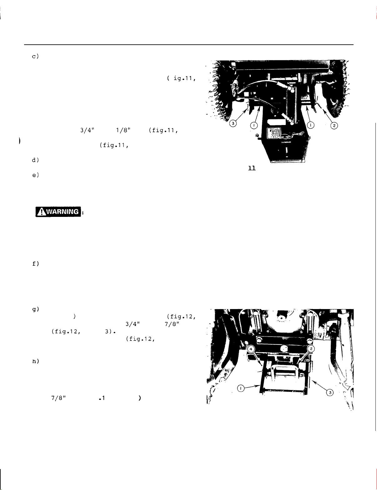
ASSEMBLY
-
SUBFRAME
Sitting on
set
parking brake and, using
the
tractor
seat,
start
the
hydraulic
engine,
valve lever carefully lower front end of
rame
so
that
the
subf
item
raise
1)
into
on
the
place
welded tube
subframe front section
inside
the
brackets. Lower front section until
weight
engine off.
subframe to
with
2). Lock
80mm
is
the
hair
off
the
Attach
the
front attaching brackets
x
17
the
pin in
pin (fig.11,
the
front
the
tires.
front end of
pin (fig.11,
place
with a 4mm
item
hose support brackets.
f ig.11,
support
the
Turn
the
item
3).
If using drive kit, connect mid drive
line to tractor mid
sure yokes
RPM.
If
in subf
is
end
can fly
are
well
This
shaft turns at very high
the
collar
rame,
or
if the yoke
not secured properly, the driveline
loose
with great
causing serious injury
PTO
shaft, making
secured to shafts.
is
not locked
at
force
or
death.
to
the tractor
capable of
shaft
x
FIGURE
Before installing
the
subf
rame,
start
hydraulically
the
implement
the
the
the
front
rear
tractor
section of
male
hitch
and lift
if installed. Turn
engine off.
Attach
item
item
4mm
x
1
2)
rear
to
80mm
section of subframe (fig. 12,
the
rear
using
item
hair
hitch
the
pin (fig.12,
plate
x
the
8
pin
item
Tighten bolts on support brackets and
rear
hitch
Specification
tighten
the
to
easily. If
adjust
OM
0179 13
bracket, according to Torque
all
bolts
Table
on
on page 71. Then
the
subframe according
Torque Table. Make sure
2,
item
3
can
be
it
does not move easily,
the
front attaching brackets.
or
the
with
4).
the
removed
re
a
8
-
FIGURE
12
Page 16
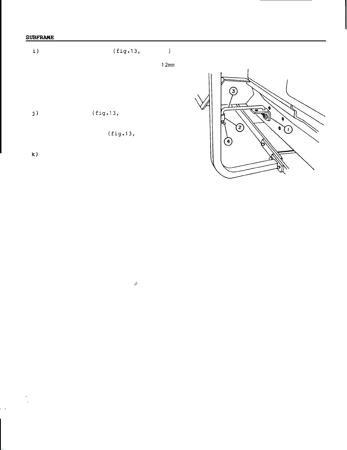
-
ASSEMBLY
Attach
tractor right hand engine side
line
30mm bolt with a lockwasher if tractor
does
bolt
loader.
Insert link
sleeve (fig. 13,
and
x
65mm
Secure
provided nylon
the two
between
first
L-bracket (fig.13,
with
not
with
valve support using 12mm
have
loader
lockwasher if equipped
or a 12mm
item
item
2)
on valve support
in
L-bracket. Secure using
hair
pins (fig.13,
hoses
hose
the
hose
together using
ties,
coupler
bracket.
placing one between
brackets and
support
item
1
rail
x
70mm
with
3) in welded
two
item
4).
the
and
the
other
the
to
in
3mm
two
x
FIGURE
13
OM
01
79
14
Page 17

DISMOUNTING
REMOUNTING
-
SUBFRAME
DISMOUNTING
Sitting on
the
attachment to transport position.
Turn engine off
to stop, and
Remove link
the
set
tractor
,
wait
for
seat,
all
parking brake.
item
movement
3) from
bracket on tractor.
Remove
pin under
remove
Sitting on
the
hairpin from
the
the
8
the
the
tractor drawbar and
pin.
tractor
seat
with
engine running, carefully lower
attachment by applying light
to
the
valve lever, until
section of
ground and
front
tires
Disconnect
place
along
Remove
Place
(fully forward)
is
flat on
Move
the
and forth
pressure. Disconnect
hoses from
tractor.
supports on
Connect
connecting
the
subframe touches
the
weight
are
off
the
the
mid driveline and
the
centre of
the
17" front pin.
the
valve in float position
,
so
that
the
ground.
hydraulic valve levers back
to
relieve
the
quick couplers on
Remove
the
the
the,
two hoses together by
the
the
the
hoses
engine side
male
pressure
the
is
off
ground.
the
subframe.
the
subframe
hydraulic
hydraulic
from
and female
couplers. Install dust plugs on
tractor couplers.
raise
8
their
rail.
the
the
rear
the
the
the
REMOUNTING
Carefully drive tractor over subframe,
running
the
Figure
subf
the
the
line
engine off and
Remove
the
front right hand
valve support bracket
11.
rame
Place
front pin points
tractor
as
so
wheel
shown
that
are
front support brackets, and
subframe
with
the
rear
the
dust plugs from
pin point
tractor drawbar. Turn
set
parking brake.
the
couplers,
and connect valve inlet and outlet hoses
to
the
tractor oil outlet coupler.
Sitting on
the
tractor
Seat,
engine, and carefully lower
hitch
attachment), using
hydraulic valve lever, until subframe
front pin points
brackets, and until
the
front
Attach
the
to
the
place
tires.
the
front end of
Stop
front attaching brackets
x
17" pin. Lock
with
a
4mm
x
Install hoses in
inside
the
the
80mm
the
the
weight
engine.
the
subframe
the
hair
hose support
are
brackets.
the
Connect
mid PTO,
e
on page 13.
mid driveline to
as
per
instructions of section
Sitting on tractor
running, carefully
seat
raise
the
with
male
the
attachment) completely using
hydraulic valve lever. Turn engine
wait
for
all
off and
movements to stop.
over
in
the
under
that
is
in
start
male
the
front
is
off
with
pin in
pin.
tractor
engine
hitch
the
Carefully back
subframe
running
over
the
not back over
hydraulic hoses.
OM
0179
the
tractor over
as
shown in Figure
the
front right hand
valve support bracket.
the
driveline
or
the
11,
tire
Do
the
Attach
pin through
attachment.
Attach
bracket and
hair
15
rear
section using
the
Secure
link (fig.13,
secure
pin.
the
8
subframe and drawbar
with
the
hair
pin.
on
underside
item
3) to
with
Page 18
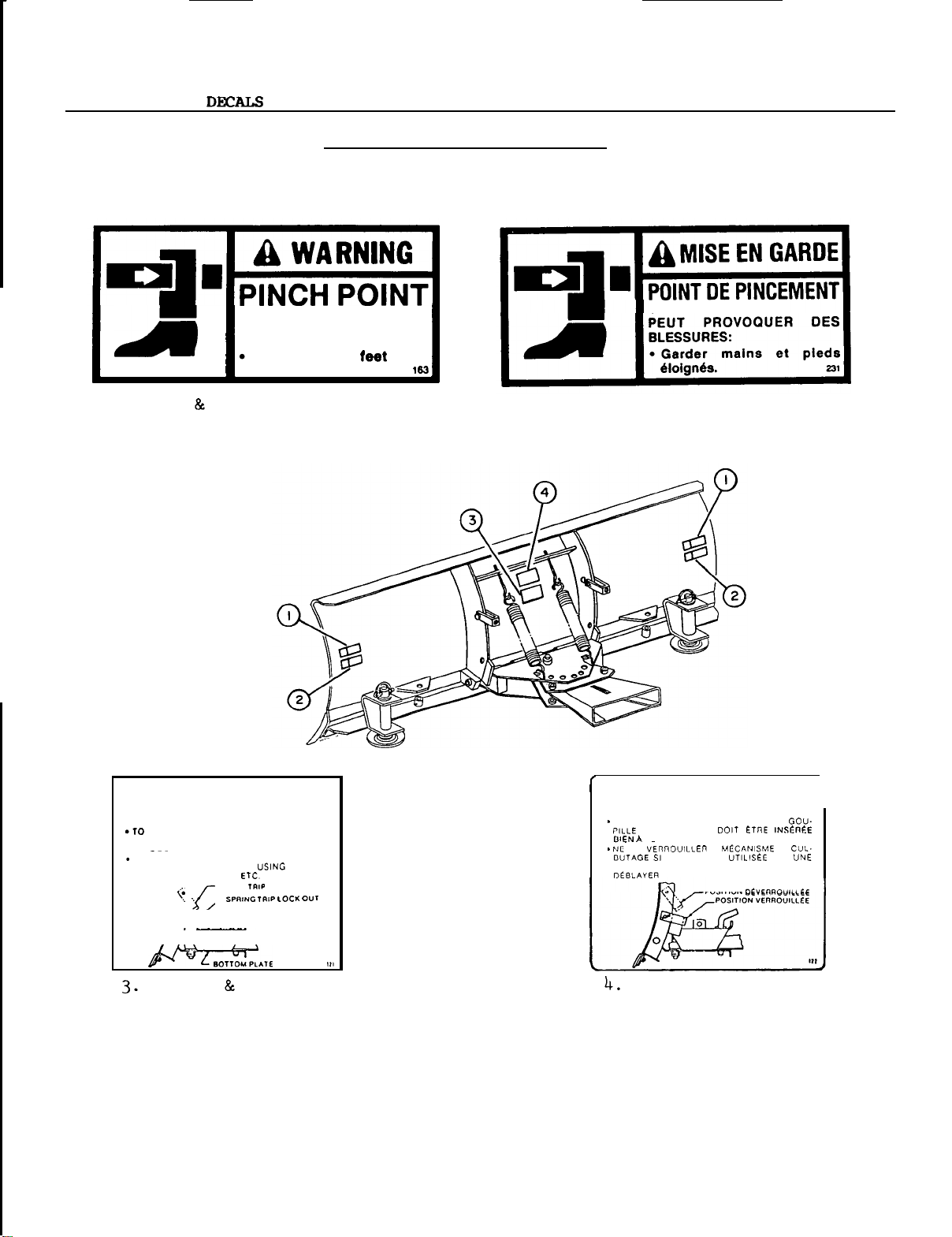
1
BLADE
1.
-
SAFETY
(U.S.A.
AVOID
FRAME
Keep
CANADA)
REPLACE
INJURY
F
IMMEDIATELY
R
O
M
PIVOT AND STOPS:
hands
and
away.
IF
2.
DAMAGED
(CANADA
C
only)
H
A
S
SIS
PIVOTANT.
IMPORTANT
PREVENT BLADE DAMAGE MAKE SURE
BLADE ANGLE ADJUSTMENT PIN
THROUGH THE BOTTOM PLATE.
.
DO
NOT USE BLADE
WHEN PLOWING SNOW. WHEN
OR
ROUGH CONOITIONS. ETC.
0
(U.S.A.
OM
0179
TRIP
SPRING
IS
INSERTED
SPRING LOCK OUT
OPERATION
CANADA)
16
IMPORTANT
POUR NE PAS ENOOMMAGER LA LAME. LA GOU-
FOND
PAS VEnnOUILLEn LE MECANISME
LA
LAME
SURFACE ROCHEUSE. RUGUEUSE OU POUR
(CANADA
EST
POSITION DEVERAOUILLEE
only)
DE
sun
I
Page 19
OPERATION
-
BLADE
OPERATING
1.
RAISING
See
page
2.
HYDRAULIC
When
the blade rotates
direction to
CONTROLS
AND
LOWERING
'RAISING
7.
ANGLING
LOWERING
the valve handle
the
left, and pulling back
FRONT
in
BLADE
ATTACHMENTS'
is
pushed forward,
a counterclockwise
on handle rotates the blade to the right.
See subframe or tractor operator's manual
for accessory valve location.
Before
turn
brake
making any adjustment,
engine
off
and
set
.
on
parking
RIGID
NOTICE
ground
To
trip spring lockout brackets
holes, hooking over
Attach
pins and secure
SKID
BLADE
OPERATION
Use
speeds
rigid blade
up
to
2
mph.
obtain rigid blade opera
the
in
SHOE
place
ADJUSTMENT
with
With
the 3/8"
3mm
x
only
to
for
the
low
the
lower
blade frame.
x
1
7/16
65mm hairpins.
Raise blade to transport position. Remove
the linchpin
skid
shoes (fig.1,
shim
item
Remove or add
placing
washers on under side of support brackets
for more clearance (there
at least one
shim
washer on top side
must
always be
of
support bracket). Reinstall linchpins.
"
OM
0179
17
Page 20
BLADE
-
MAINTENANCE
Maintenance
1.
Remove dirt from pivot points and angling
cylinders every 4 hours of operation,
especially in cold
Lubrication
1.
Grease
the
of operation.
2.
Oil
Before storage
1
.
Clean
2.
Repaint
3.
When
parts.
against rust.
the
rod end of
all
moving
the
blade
all
parts
blade
Apply
DISMOUNTING
weather.
fitting on pivot pin and
each
cylinder every
parts
thoroughly.
oil
every month.
from
which
is
dry,
liberally
paint
oil
to
has
all
8
hours
worn.
moving
protect
at
4. Store blade in
a
dry
place.
DISMOUNTING
a)
Set
tractor
and remove ignition key. Place lift lever
in
float
pressure by moving valve handles back and
forth.
Remove linchpin (fig.4,
quick
c)
Move
3)
Disconnect blade cylinder
to
hitch
the
the
parking brake,
position
latch.
quick
unlock posltlon (rearward).
and relieve hydraulic
hitch
lever (fig.4,
item
stop
4)
hoses
from
tractor.
engine
the
item
from
OM
0179
18
Page 21
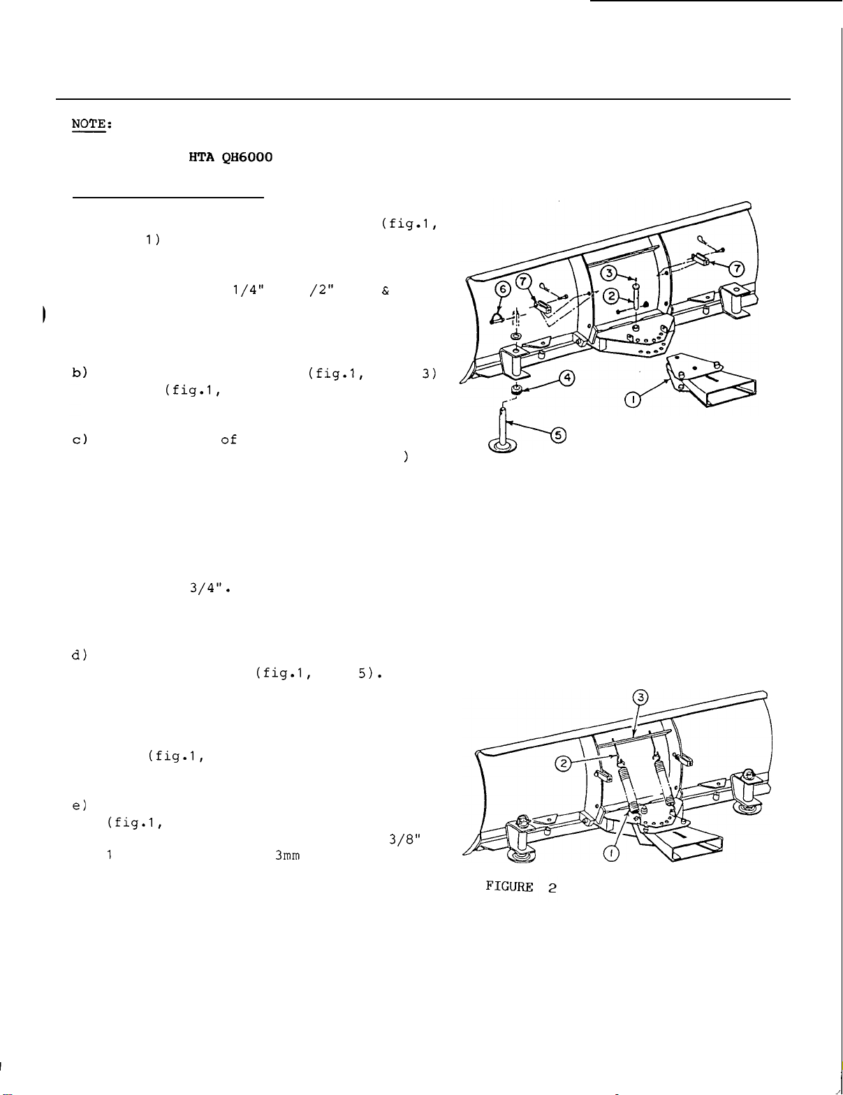
ASSEMBLY
-
BLADE
Before
tractor,
with
STEP
a)
1:
Install
item
on
top
long pin (fig.
in
place
mounting
a
BLADE
the
inside
your
ASSEMBLY
this
tractor
female quick
the
blade
side) using a 23/32
1
,
item
with
a
x
lock nut on the underside of
attachment.
Install grease fitting
on pin (fig.1,
Hook
one end
item
the
attaching brackets (fig.
the
blade
bolt
each
the
(fig.2,
spring. Insert
holes
(fig.2,
Secure
Adjust eye
frame . Place a 5/16
item
2) on
the
in
the
upper
item
the
3)
eye
bolts
as
bolts
so
lengthens
other
5/16" nuts.
attachment on your
must
subf
rame.
hitch
be
mounted
attachment
"
dia.
x
4
2) . Lock
1 1
the
bolt
the
item
2).
two springs
2,
to
item
" x 5" eye
the
eye
blade
other
bolts
cross
end of
through
member
shown in figure
with
5/16" nuts.
that
bolts
the
spring
with
(slot
11/16
pin
nylon
blade
the
1
on
two
2.
"
FIGURE
1
Place four
over
each
one skid
underside.
each
skid
shim washers
skid
shoe
shoe
in
Place
shoe
each
two
on
bracket and secure skid
item
pins
Install
the
blade.
7/16" pins and
OM
0179
the
item
Lock in
trip
7) in
6).
spring lockout brackets
the
(fig.
1
,
item
item
support bracket from
top
the
place
shim
upper
washers
side of support
shoes
x
with
holes
with
behind
the
65mm hairpins.
4)
over
linch
x
19
Page 22
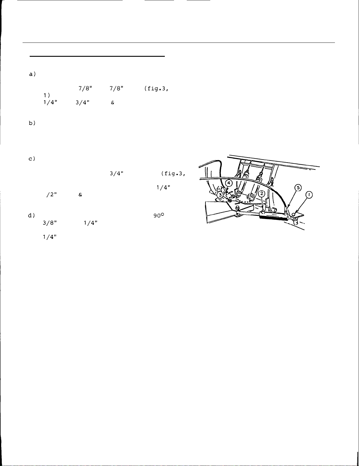
BLADE
-
ASSEMBLY
STEP
2:
HYDRAULIC ANGLING INSTALLATION
Install base end of
the
blade (cylinder ports on top side)
using two
.
Lock
Place
the
rod end port of
thread sealant.
Attach
female quick
outward) using
item
of
the
1
quick coupler
dust
the
x
1
a breather plug (fig.3,
rod end of
3). Lock
female quick
bolt
male
x
end of each hose, placing
cap
ring on
the
two cylinders on
x
2
pins on
hitch
the
the
nylon lock nut.
sealant,
with
the
the
nylon lock nut.
each
each
pins
rubber dust
hose before connecting.
cylinder to
(grease fittings
x
3
on the upper side
hitch
attach
item
underside
item
cylinder using
"
pins (fig.3,
with
a
cap
the
with
2)
in
the
x
elbow
at
the
rubber
1
.
FIGURE
3
e)
Install
the
(fig .3,
and identify
plastic
33
"
hand cylinder (fig.3,
thread sealant, and identify
with
OM
0179
the
base
end port of
hose
the
other end
the
item
ring. Attach
to
yellow
4)
using thread sealant,
this
the base end
hose
plastic
of
the
40
"
hose to
left hand cylinder
with
the
item
ring.
the
green
other end of
port
of right
5)
using
this
hose
20
Page 23
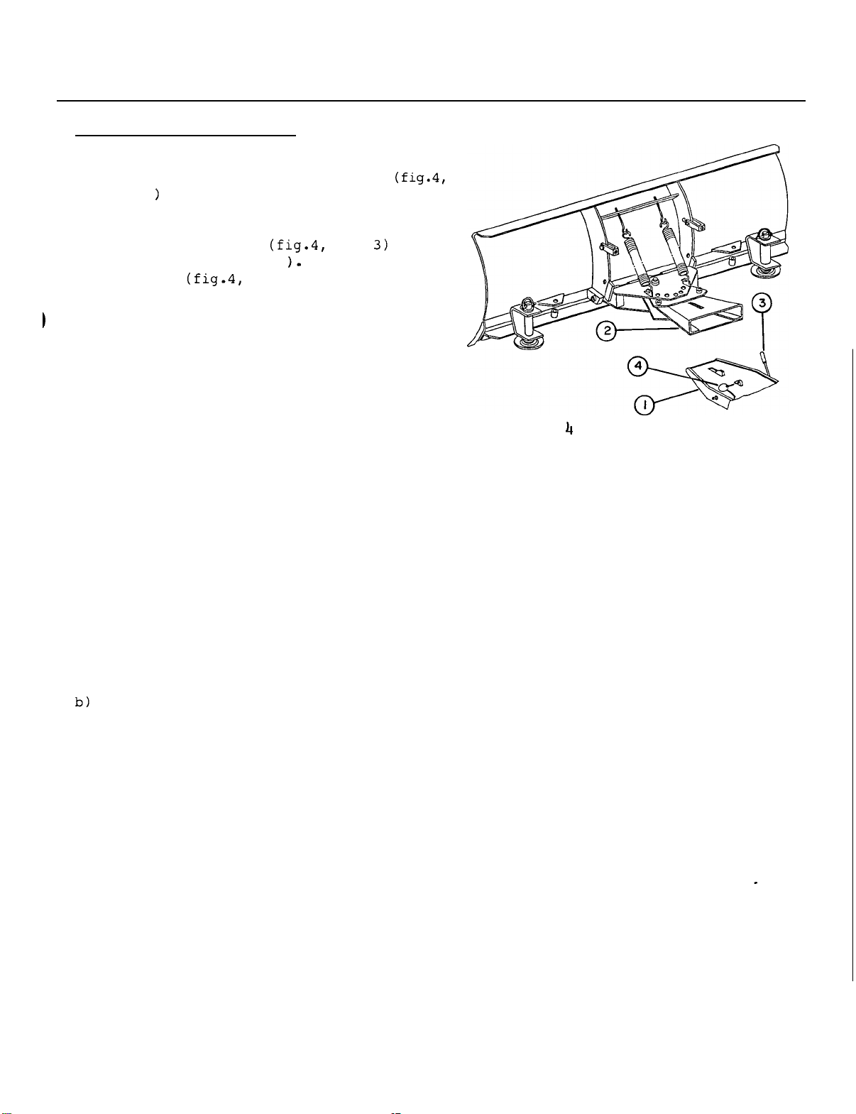
3:
STEP
a)
BLADE INSTALLATION
Insert
item
quick hitch (fig.4,
off and
by
position (fully forward
linchpin (fig.4,
the
1
on
moving
male
the
set
the
Escaping hydraulic fluid (oil)
under pressure can penetrate
causing
0
serious
Do
not use your hands
leaks.
paper
0
Stop
engine and relieve pressure
moving valve handles back and
before
lines.
0
Tighten
starting
If
any fluid
it
may
result
is
not surgically 'removed within
hours
by
a
of injury.
quick
tractor into
parking brake. Lock in place
lever (fig.4,
item
hitch
item
section (fig.4,
the
blade female
2)
,
item
Secure
4).
turn engine
to lock
latch
the
with
skin
injury.
to
Use
a
piece
to
search for leaks.
of
check
cardboard
for
or
by
forth
connecting
all
engine
is
injected into
in gangrene
doctor familiar
or
disconnecting
connections before
or
pressurizing
if
with
the
the
this
lines.
skin,
fluid
a
few
form
FIGURE
ASSEMBLY
-
BLADE
second from
the
and
top female quick coupler on
hand side of tractor.
OM
0179
top
female quick coupler,
right hand cylinder hose to
the
to
right
the
the
21
Page 24
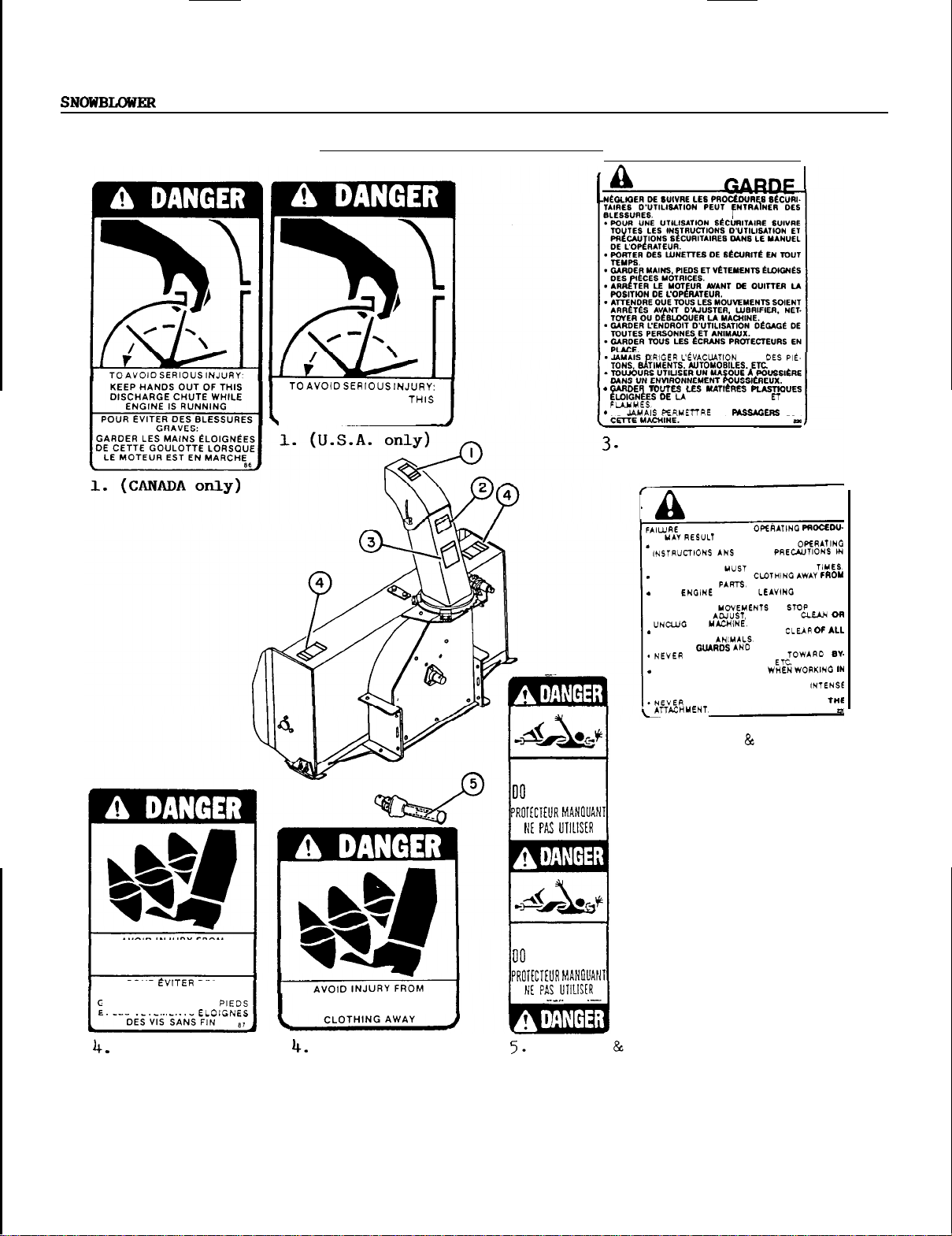
-
SAFETY
DECALS
REPLACE
KEEP HANDS OUT OF THIS
DISCHARGE CHUTE WHILE
.
ENGINE
IMMEDIATELY
IS
RUNNING
IF
DAMAGED
MISE
NE
(CANADA
EN
MLEUR INTENSE
DE
only)
WARNI
TO
RES
.
FOLLOW SAFE OPEhATINO PR~ou-
FOR SAFE OPERATION FOLLOW ALL
OPERATOR'S MANUAL.
EYE PROTECTION
KEEP HANDS, FEET AND CLOTHINO AWAY
POWER DRIVEN
STOP ENOlNE BEFORE LEAVINO OPERATOR
POSITION.
.
WAIT
FOR
STARTING
KEEP THE AREA OF OPERATION CLEAR OF
PERSONS AND ANIYALS.
.
KEEP
ALL
STANDERS. BUILDINGS.
ALWAVS USE A DUST MASK WHEN WORKINO
DUSTY CONDITIONS.
.
KEEP PLASTIC MATERIALS AWAY FROM INTENSE
HEAT AND OPEN FUME.
SAFETY
BE WORN
ALL
TO
ALLOW PASSENGERS
DES
SUR
m
LUBRICATE.
SHIELDS
CARS
N
AT
ALL
IN PLACE
ON
G
BEFORE
.
AVOID
INJURY FROM
ROTATING AUGER
KEEP
HANDS. FEET AND
CLOTHING AWAY
POUR
BLESSURES GRAVES:
GARDER LES MAINS, LES
ETLES VETEMENTS
(CANADA
OM
0179
only)
ROTATING AUGER
KEEP HANDS, FEET AND
(U.S.A.
only)
22
SHIELD
MISSING
NOT
OPERATE
SHIELD
MISSING
NOT
OPERATE
(U.S.A.
Visible only
is
missing.
2.
(U.S.A.
CANADA)
if
shield
CANADA)
Page 25
The
safe operation of
responsibility
of
should be familiar
snowblower and
all
starting operation.
the
with
this
operator.
machine
The
is
operator
the tractor and
safety practices before
OPERATION - SNOWBLOWER
the
NOTICE
To avoid damage to
all
bolts after
of operation.
SNOW
REMOVAL
1.
Read
before using
Be
and proper
to stop
the
Operator's Manual carefully
the
tractor and snowblower.
thoroughly familiar
use
of
the
the
unit and disengage
quickly.
2.
Make
before engaging
3.
Make sure
Check
4.
make sure level
sure
the
the
the
oil level in
blower
the
auger and fan operate freely.
is
and if necessary, add
5.
GL-5
Check
SAE
the
90
three
gear
oil.
shearbolts, one on each
auger section and one between
gearbox for proper tightness.
the
snowblower,
the
first 10 hours
with
the
controls
equipment. Know how
the
controls
is
clear
PTO.
the
worm gear box
up
to the side plug,
AGMA
of snow
5EP or
the
fan and
API
so
that
the
Adjust
snowblower skid shoes
run level.
7.
Wear
adequate
winter outer garments
operating equipment.
WORK
Working ground speed
depth and density of
Normally, ground speed
7
mph
for light, dry snowfalls
1
-
3 mph for heavy, wet or drifted snow.
To
transport, disengage
the
snowblower to
OM
0179
SPEED
full
will
the
will
depend on
snow to be cleared.
range from 4 to
the
PTO,
transport height.
and
while
the
raise
23
Page 26
SNOWBLOWER - OPERATION
OPERATING CONTROLS
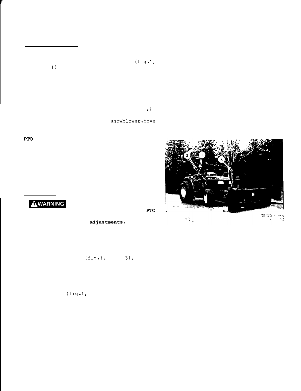
HYDRAULIC CHUTE ROTATION
The
hydraulic chute rotation lever (fig.1,
item
of
rotate chute to
and rearward
is
the
valve. Push
located on
the
to
clockwise.
the
left hand side
the
lever forward to
left (counterclockwise)
rotate to the right,
1
or
RAISING
AND
LOWERING THE SNOWBLOWER
Move
item
and forward to lower
the
the
hydraulic lift lever (fig
2)
rearward to
raise
the
the
lever fully forward for float position.
OPERATION
The
mid PTO
the
on
PTO lever on left side of
Engage attachments
only. To activate or engage
on
the
PTO
is
selected by pulling back
at
low
engine RPM
PTO,
lever on right hand side of
instrument panel, push down to disengage.
ADJUSTMENTS
To avoid personal injury, be
sure the tractor engine is
disengaged,
before
making
and
all movement has stopped
any
off,
DEFLECTOR ADJUSTMENT
Set
the
angle of deflector according
the
distance
set
the
deflector knobs
the
deflector, and tighten
the
snow must be thrown.
deflector angle, loosen
item
the
securely.
snowblower
seat.
lift up
the
to
To
the
two
adjust
two knobs
,
FIGURE
1
SKID SHOE ADJUSTMENT
Adjust
shoes
the
the
run (fig.1,
skid
shoes
snowblower
item
according
so
that
4)
level. Adjust
to
the
being cleared. Adjust downward for rough
or
uneven surface conditions
stones
are
not thrown
with
the
adjust upwards for smooth surfaces.
Adjust both skid
to
keep
OM
0179
the
shoes
cutting
edge
to
the
same
level.
the
skid
surface
so
that
snow, and
height
24
Page 27
OPERATION - SNOWBLOWER
:
PLUGGED CHUTE
DISENGAGE THE POTOO.,
MOVEMENT
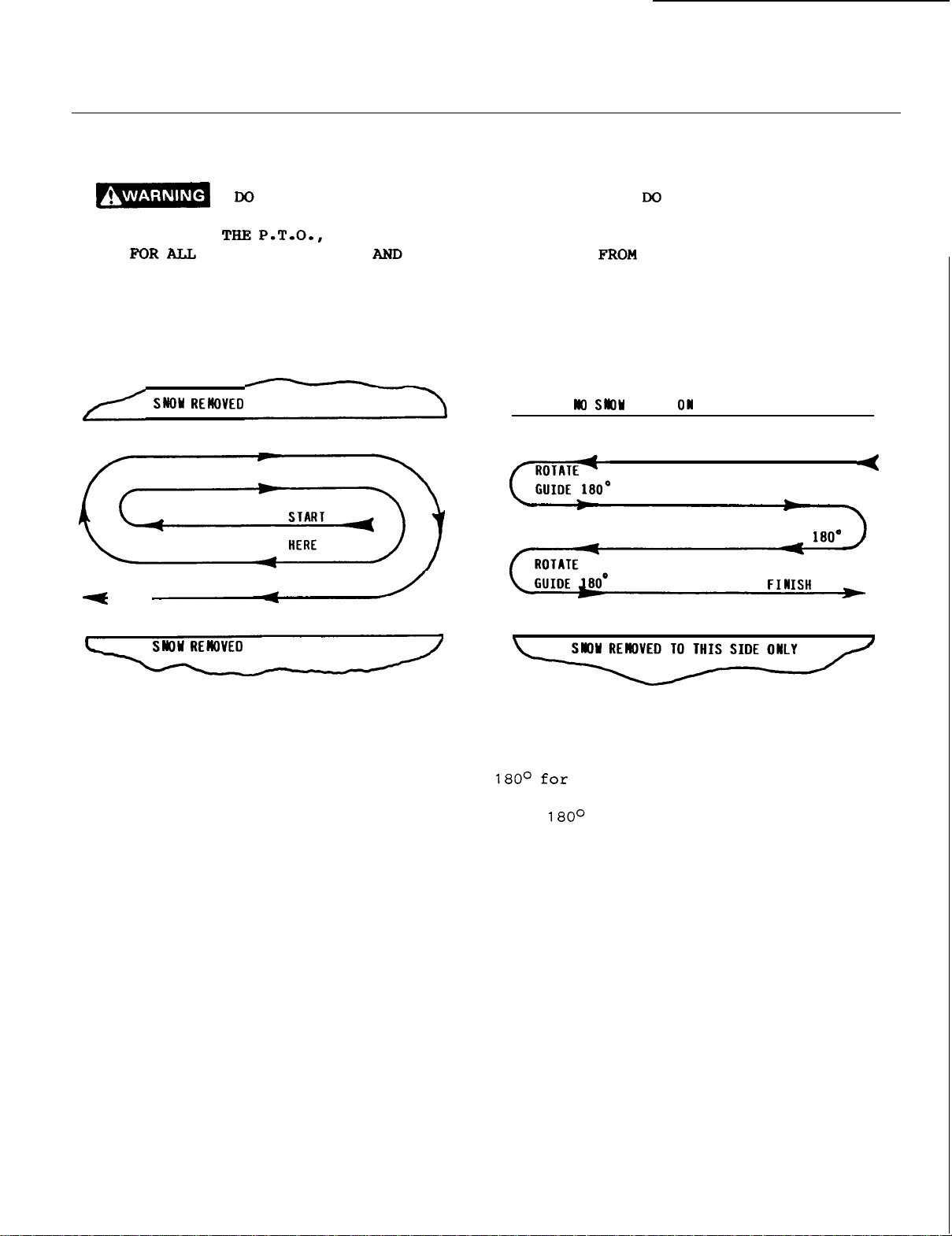
Adefinite pattern
patterns
second removal
F
I
HERE
NISH
will
avoid throwing snow in unwanted places
of
NOT USE
OF
SNOW WHILE TRACTOR ENGINE IS RUNNING. IF THE CHUTE PLUGS
TO
of
operation
snow.
TO
EITHER SIDE
HANDS
SHUT
STOP,
SNOW
REMOVAL
OR FEET
OFF
THE TRACTOR ENGINE,
METHODS
TO
UNPLUG CHUTE,
THEN CLEAR THE SNOW
is
required to thoroughly clean
REMOVE
THE CHUTE.
as
P
ILED
NOT ATTEMPT
THE IGNITION
the
snow area.
well
as
eliminating
THIS
SIDE
TO
KEY,
START
HERE
ROTATE
GUIDE
HERE
CLEAR
,
WAIT
These
a
TO
EITHER SIDE
Where
to
long driveway,
start
to
it
is
possible to throw
the
left and right (above), as on a
it
is
in
the
middle. Plow from one end
the
other, throwing snow to both
sides without changing
the
discharge guide.
OM
0179
the
snow
advantageous to
the
direction of
If
the
snow can only be thrown to one side
of
the
on
driveway or sidewalk (above)
the
opposite side.
At
the
end
,
of
start
first pass, rotate the discharge guide
the
each
guide
in
25
return
succeeding pass, rotate
to maintain direction
the
same
area.
pass.
At
the
the
end of
discharge
of
throw
the
Page 28
-
TIRE
PRESSURE
-
Inflate front
wheel
pressure recommended by
owner's manual.
-
Adjust
tractor
rear
tires
to
owner's manual.
MAINTENANCE SERVICE
1.
Always use
on
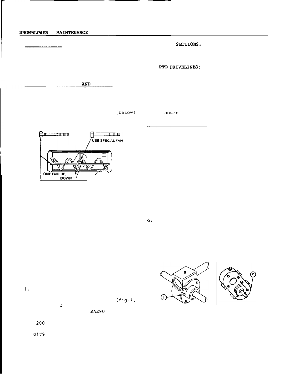
the
shear
as
bolts on
shown on shearbolt decal (below)
inside
USE SPECIAL
SHEAR
ONE
END
the
fan, and
the
collector
AUGER
BOLT
ONLY
special
the
the
tires
to maximum
the
tractor
specifications in
STORAGE
shear
special
bolts
grooved
auger sections,
housing.
SHEAR BOLT ONLY
2.
AUGER
each
on
auger section every 24 hours
of operation
3.
fitting every
Slide drive shaft
sliding surfaces
8
hours of operation.
4.
SUBFRAME:
Grease
Grease
or
once a year.
Grease
8
hours
apart
with
all
the
each
of
operation.
grease every
fittings on lift
and on subframe attaching points every
8
END
OF
SEASON STORAGE
1.
2.
3.
Clean
Repaint
has
When
moving
all
the
snowblower thoroughly.
all
parts
from
which
worn.
the
snowblower
parts.
Apply
is
dry,
oil liberally
surfaces to protect against
fitting
u-joint
and coat
paint
oil
all
to
rust.
Check
2.
tervals for
sure
the
the
shear
proper
blower
bolts
at
frequent in
tightness
is
in safe working
condition.
Never
3.
the
open flame or
Allow
store
the
tractor
with
fuel tank inside a building
the
sparks
engine
are
to
cool before
storing in any enclosure.
a
Run the snowblower
4.
blowing snow
the
auger and
Provide adequate blocking
5.
working under
the
raised position.
to
the
the
few minutes after
prevent freeze up of
impeller.
snowblower when in
LUBRICATION
GEARBOXES:
Check
the
oil level in
gearboxes every month. Make sure
is
oil
items
SEP,
Replace
up to level plug (fig.1,
1
2)
If necessary add
or API GL-5 SAE90 gear oil.
oil every two seasons
hours
whichever comes first.
to
be
fuel in
where
present.
before
the
AGMA
or
-
4.
Lubricate
the
snowblower
as
instructed
above.
5.
List
the
replacement
be needed before
the
Store
FIGURE
snowblower in a dry
1
parts
the
next season.
that
will
place.
OM
26
Page 29
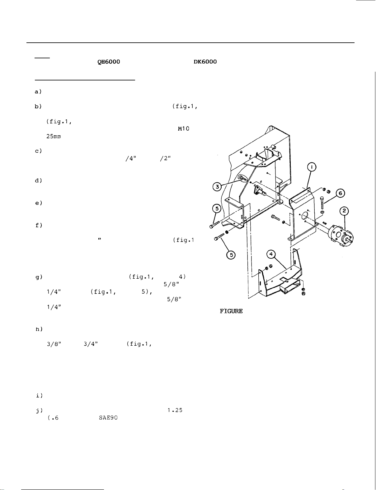
ASSEMBLY
-
SNOWBLOWER
NOTE:
STEP
Before mounting
with
1:
Turn snowblower
Place
item
the
a
HTA
SNOWBLOWER
ASSEMBLY
with
reduction gearbox support (fig.1,
1)
on back of reduction gearbox
item
2). Secure
reduction gearbox using
Remove paint from blower
shaft and install
the
impeller
Apply anti
shaft keyway.
-
seize compound on
input shaft.
Carefully align
with
the
impeller
Secure
the
two 5/16
item
the
back of
"
x
3)
with
housing and
outside of
the
shaft and
top of
the
1
Allen
the
head
a
lockwasher and nut on
the
support.
this
attachment on your tractor, your
subframe and
a
HTA
auger facing down.
the
support
three
impeller
a
1
1
the
impeller
reduction gearbox hub
the
key
seats.
the
gearbox support to
impeller
inside
housing using
set
screws
the
impeller
to
input
the
tractor
must be mounted
drive kit.
,
Install female
hitch
back of snowblower using two 5/8"
item
and nuts in top holes, and two
holes.
Secure
support to
flatwashers on top of
lockwasher and nut on
Securely tighten
the
securing
Set
Fill
OM
01
Do
not tighten yet.
the
bottom
the
female
x
3
all
support, and tighten
the
female
snowblower
hitch
with
skid shoes on
reduction gear box
liter)
79
of
part
of
hitch,
the
support, and
the
four bolts securing
the
to
the
with
gear oil.
item
x
x
the
gearbox
using two
item
6) and
underside.
four bolts
snowblower.
the
ground.
on
1
1
1
a
27
Page 30
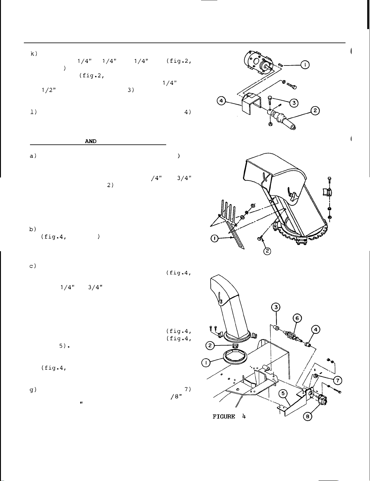
SNOWBLOWER - ASSEMBLY
and
item
place
1
in
x
the
shaft keyway. Install drive
line yoke (fig.2,
shaft and
secure
bolt (fig.2,
Tighten bolt and
the
gearbox input shaft
x
1
item
in
place
2)
over reduction
with
item
set
screw
securely.
-
a
2
Install driveline guard (fig.2,
on
the
reduction gearbox, using one
1
5mm
bolts and lockwashers. Tighten securely.
STEP
2:
CHUTE
Install
the
chute and
the
chute
hand guard (fig.3,
with
the
the
bottom section outside
chute base ring.
bolts
outside of
(fig.3
item
the
HYDRAULIC ROTATION
top
portion inside
Place
with
two
the
chute, through
then through hand guard and secure
bolt
nut. Torque
Place
Apply grease
it
Place
secure
item
with
the
will
the
with
2)
a
flatwasher, lockwasher and
to
plastic
item
on
contact
chute on
two
on
front
9-1 1 lbs. f
anti-friction insert
1
over
top of
the
chute base.
the
plastic
retaining
side
of snowblower using
t.
the
this
four
nuts.
Do
not tighten.
item
10
item
1
on
the
the
1
head
the
on
the
chute
each
chute base.
insert
where
insert and
x
FIGURE
FIGURE
2
3
d) Insert
(fig.4,
e)
Insert
item
item
the
4) in
long
3) in
1
11/16" long bushing (fig.4,
the
the
rotation bracket (fig.4,
plastic
tube weldment.
the
1
5/16
"
item
f)
Install longest tube end of rotation worm
item
6)
in
the
bushing in rotation
bracket.
Insert locking collar (fig.4,
over rotation worm. Install
3/16" x
1
key in
the
hydraulic motor
a
shaft keyway.
OM
0179
bushing
item
1
28
x
Page 31
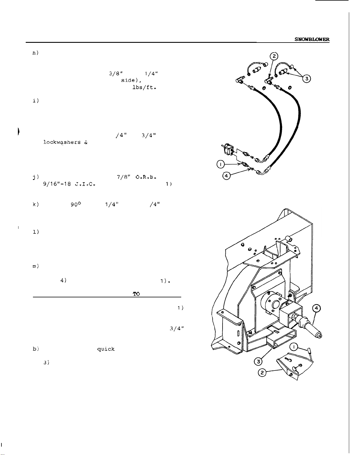
ASSEMBLY
-
Install hydraulic motor (fig.4,
on rotation bracket and inside rotation
worm. Secure
bracket using
flatwashers (on motor
and nuts. Torque
Install rotation bracket assembly on
under side of chute base'
inside bushing (fig.4,
weldment. Secure assembly
retaining plate on upper side of
base
sliding
locking
locking
Install
each
ing female (fig.5,
hoses.
lip and four
worm
collar
collar
a
port
the
motor on
two
to
35-42 lbs/ft.
x
the
1
lip
item
with
1
nuts.
against rotation bracket and
connector 7/8"
of hydraulic motor. Tighten.
elbow 1/4" male
Remove linear
toward
set
screws
male
item
worm,
and
(fig.5,
2)
at
x
item
rotation
and worm
3) in tube
two more
8)
chute
bolts,
play
tighten
all
bolts.
by
the
male
item
1
male end of
in
x
-
FIGURE
5
Using thread sealant,
coupler
3) on
on hose before installation).
Connect
motor,
with
each
placing a flow restrictor
rubber, dust cap (fig.5,
elbow (dust cap ring must be
the
two hydraulic hoses
attach
item
STEP
a)
3:
ATTACHING SNOWBLOWER
Move quick
rearward to
tractor behind snowblower and
male
from
Introduce
2)
it
it
blower and move
position. Secure
quick
the
into female quick
is
parallel
all
hitch
the
hitch
ground.
male
the
way into female section.
lever (fig.6,
unlock position. Position
to approximately 3/4"
hitch
hitch
Raise
to female section and insert
the
male
lever forward to locked
latch
section
with
a
male quick
item
to
(fig.5,
item
QUICK HITCH
item
raise
(fig.6,
(fig.6,
linch pin.
front
so
Raise
item
item
that
the
FIGURE
6
OM
0179 29
Page 32

SNOWBLOWER
-
ASSEMBLY
Connect snowblower driveline (fig.6,
4)
to
PTO
shaft in frame by sliding back
locking collar on drive line yoke and
pushing yoke over shaft until locking
ring snaps back.
This
shaft turns
If
collar
tractor
end,
not secured properly,
loose
with
serious injury
Adjust skid shoes according
instructions on
e)
Release
moving valve handles back and forth.
pressure from hydraulic system by
is
not
or
if yoke
great force
or
death.
page
locked
the
capable
24.
at
to
at
blower end
driveline
of causing
to
adjustment
very high
shaft
Escaping hydraulic fluid
under pressure can penetrate
the
causing serious injury.
Do
not use your hands
leaks.
paper
0
Stop
moving valve
before
lines
0
Tighten
engine
If any fluid
it
may result in gangrene
Use
a
piece
to
search
engine
for
and
handles
connecting
.
all
connections
or
pressurizing lines.
is
injected into
leaks.
relieve pressure by
not surgically removed within
a
by
in j ury
doctor
.
familiar
with
to
check for
of cardboard
back
or
and
disconnecting
before
the
if
the
a
few
this
starting
fluid
form
can
(oil)
forth
skin,
hours
item
at
is
fly
skin
or
is
of
chute
quick coupler on right side of subframe.
that
turns chute towards
direction. If not, reverse hoses.
OM
Match
using
0179
hydraulic hoses to female couplers
the
colored
rotation hoses
moving valve lever rearward
the
right in clockwise
plastic
rings.
to
female
30
Page 33
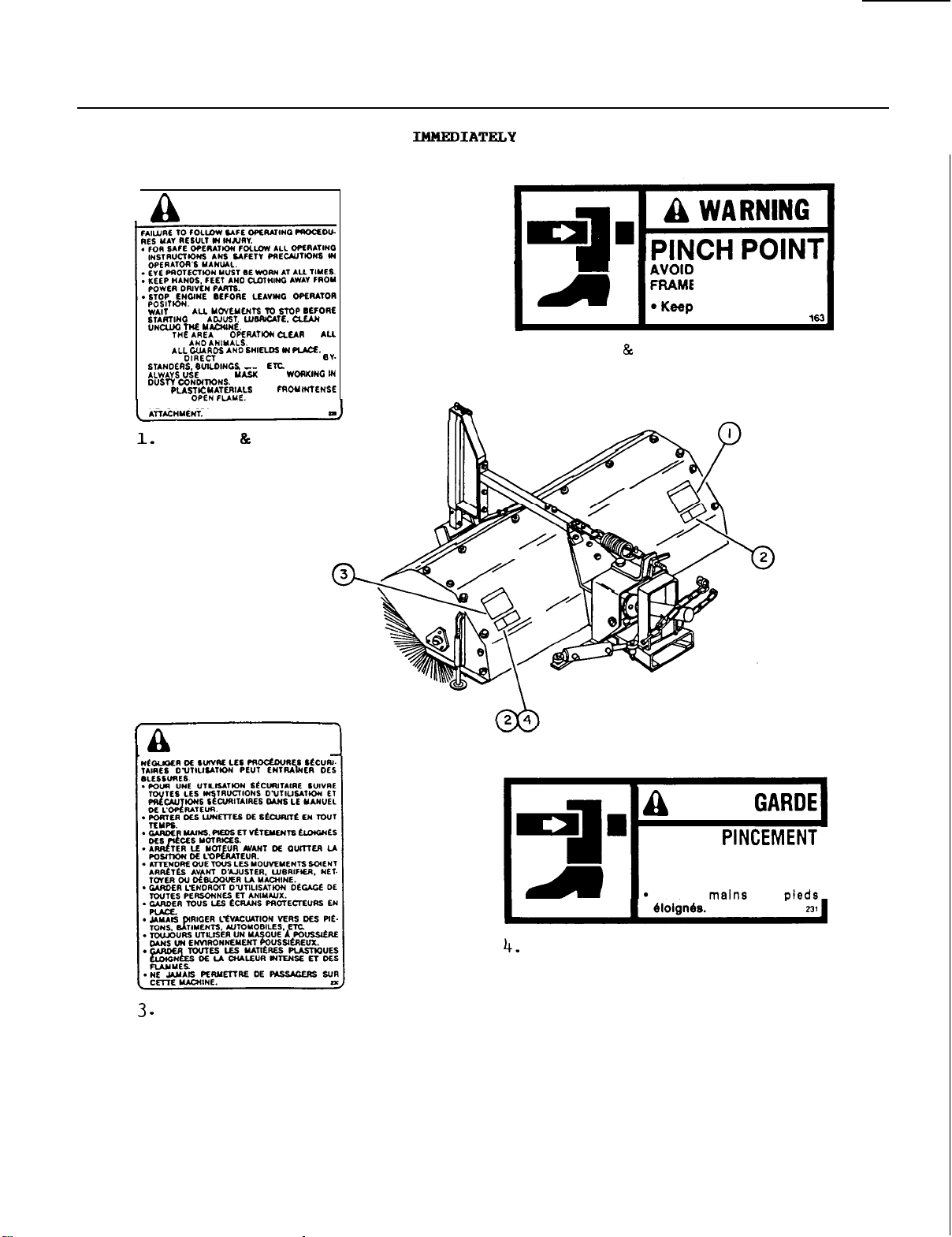
SAFETY
DECALS - BROOM
I
KEEP
PERSOHS
KEEP
UEVER
KEEP
HUT
NEVER
W
A
RNI
F
O
R
TO
OF
DISCHARGE TOWARD
A
OUST
AND
ALLOW PASSENGERS ON THE
(U.S.A.
CARS
WHW
AWAY
CANADA)
N
G
OR
OF
REPLACE
IF
2.
DAMAGED
(U.S.A.
FRAME
Keep
CANADA)
INJURY
PIVOT
hands
AND
and
F
ROM
feet
STOPS:
away.
OM
MISE
(CANADA
0179
EN
GARDE
only)
31
(CANADA
M
I
S
E
E
N
POINT DE PINCEMENT
C
H
A
S
SIS
Carder
PIVOTANT.
et
PEUT PROVOQUER
BLESSURES:
only)
DES
I
Page 34
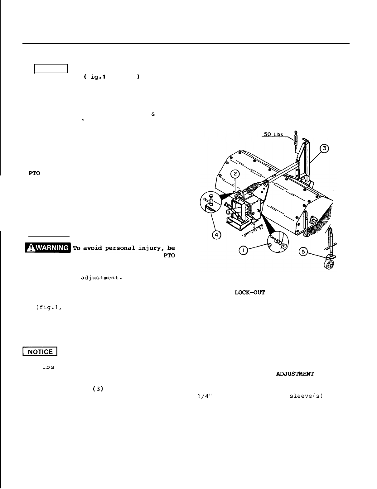
BROOM - OPERATION
OPERATING CONTROIS
NOTICE
pivot lock
most
Before operating, make sure broom
f ig.1
extended
,
item
1
pin
is
position to allow broom to
follow ground variations.
RAISING AND LOWERING BROOM
Refer
ATTACHMENTS
to
page
.
7
'RAISING
LOWERING
HYDRAULIC ANGLING
Moue left valve handle forward to angle
broom to
to angle broom
the
left and move handle rearward
to
the
right.
OPERATION
The
mid PTO
on
the
seat.
on
instrument panel, push down to disengage.
To activate
the
PTO lever on right hand side of
is
selected
PTO
lever on left hand side of
or
by pulling back
engage PTO, lift
ADJUSTMENTS
in
its
up
50
Lbs
sure tractor engine
disengaged, parking brake
is
off,
is
the
set and
all movement has stopped before
making any adjustment-
BRUSH GROUND CONTACT ADJUSTMENT
Turning
decreases brush ground contact. Turning
ground
increases brush ground contact and must
be
used only to compensate brush
lifted by
50
premature brush
the
ground contact wing nut
item
2)
in a clockwise direction
contact
Adjust
the
,
more than
handle counterclockwise
so
that
front, weighs approximately
wear
broom head when
this
and overheat gearbox.
wear.
could cause
FRONT WHEEL JACK
Adjust
ground, and turn jack handle two full
turns counterclockwise,
barely touch
OM
0179
so
that
the
brushes
ground.
so
rest
that
on
brushes
the
FIGURE
1
OSCILLATION LOCK-OUT PIN
Set broom head
and
place
position to prevent broom from
oscillating side
was
designed
wear,
work on uneven ground or when using
side
unlock pin only for light duty
casters.
OPTIONAL CASTER
Required for: lawn thatching and/or leaf
raking. Adjust
parallel
pin (fig.
to
to
prevent uneven brush
WHEELS
height
to
female
1,
item
4)
in "lock
side. This feature
to
the
spacer
upper or lower
Adjust according to type of operation
(see
next page for applications).
32
side
of
stand support.
hitch
"
(5)
nearest
Page 35
OPERATION
-
BROOM
PREPARING
1.
Read
Be
and
2.
Do
operator on
any rider on
3.
If tractor
optional cab, operator must
protec'tion (face shield
operation.
4.
Be
of tractor, broom
area
Contact
discharged by broom can cause serious
injury
FOR
SWEEPING
the
thoroughly familiar
proper
not allow anyone other than
use of
the
tractor.
the
is
attachment.
not equipped
the
equipment.
with
Do
controls
not
wear
etc.)
sure bystanders
before operating
with
tractor,
are
completely
broom discharge
the
broom or debris
.
Remove any accumulation
snow,
ice,
dirt
or
mud from inside
and outside broom hood and from in
between bristles regularly; excess
weight
will
premature and/or uneven
unbalance
broom
causing
wear
bristles.
kind
of
Never
carpet
operate
-
broom on any
the
allow
with
eye
during
clear
broom.
of
of
APPLICATIONS
0
SNOW
REMOVAL
may
itself.
that
aware
1.
This
of
snow can be moved
is
reduced.
2.
To avoid snow being blown back on
tractor
wind blowing in
tion.
3.
The
for extra traction.
0
LAWN
THATCHING
must
:
Foreign
be
thrown
Use
farther
slowest
will
of
broom discharge direction.
broom works best on snow depth
6
"
or
less.
or operator,
the
use of
tire
chains
Optional
be
installed
objects
than
brush
the
job.
Large amounts of
if
ground speed
sweep
discharge direc
is
recommended
LEAF
RAKING
caster
to
perform
types of operation in order
limit
1
.
Set
below brush
and thatching operations.
Slower
2.
are
This
could damage
ground contact.
3.
Minimize dust by sweeping when moisture
is
possible.
excessive
caster
brush speed and ground speed
more
adequate for
will
high
(but not
ground
wheels
tips
avoid bouncing
the
lawn due
contact.
at
1
to
for leaf raking
lawn
thatching.
to
wet)
in snow
the
snow
speed
Stay
the
with
the
wheels
these
to
1
which
excessive
whenever
-
OM
tips
not
like
0179
of
the
with
a
mop.
bristles,
the
to
sides
sweep
like
of
with
a
broom
bristles,
the
GENERAL SWEEPING
1.
Minimize dust by reducing brush
and by sweeping on days
-
33
moisture
2. For light
to
angled to obtain wider sweeping
3.
Prevent damage to broom by removing
large foreign objects.
.
material,
right or
left
lots etc.)
speed
with
angle broom 12
rather
high
than fully
path.
Page 36
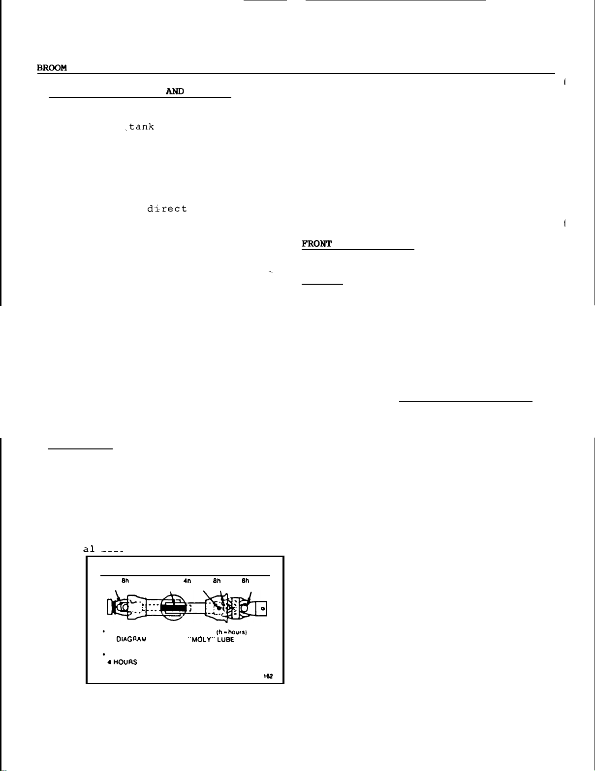
-
MAINTENANCE
MAINTENANCE SERVICE
1.
Never store
the
fuel -tank inside
where
open flames or sparks
the
present. Allow
STORAGE
tractor
the
with
fuel in
a
building
engine to cool
before storing in any enclosure.
2.
Avoid exposing broom
bristles
to
sunlight for long periods. Long
exposure
damage
3.
Provide adequate blocking before
working under
4.
Because of dust
(other than snow),
to
the
bristles.
the
broom.
raised
when sweeping
the
tractor
cleaner should be checked daily and
replaced when necessary.
5.
Check and tighten
all
hardware incl
uding factory installed hardware,
every
8
hours of operation and before
operation.
6.
Do not
alter
or modify
the
broom. If
you have any questions, contact your
dealer.
LUBRICATION
1.
B
ROOM
:
Using
a
good quality multi
purpose lubricant, lubricate
pivot points and brush ground contact
24
adjustment threads every
hours of
operation.
are
direct
will
air
-
-
all
2.
GEARBOX:
level
is
Check
up to
that
the
the
front plug before
initial operation and every
hours of operation. Change
3.
every
S.A.E.
FRONT
100
hours of operation.
140
oil.
WHEEL:
Grease
hours of operation.
TIRE
STORAGE
1.
Install a rubber dust
PRESSURE:
Inflate
cap
quick coupler.
Clean broom thoroughly.
2.
Oil
all
3.
Store broom on storage stands
4.
the
If broom bristles
5.
sunlight,
6.
Store
moving
bristles
the
protect
broom in a dry
parts.
do not touch
are
exposed to direct
bristles
gearbox
oil
40
oil
Use
every eight
to
30
psi.
on
each
hose
so
that
the
ground.
with
a
tarp.
place.
2.
DRIVELINE:
dec
OM
017
Grease
he
low.
IMPORTANT
20n
GREASE
IN
THE CENTERING UNIT MUST
ALL
POINTS
AND
USE
AS
A
as
indicated on
SHOWN
BE
GREASED EVERV
34
Page 37
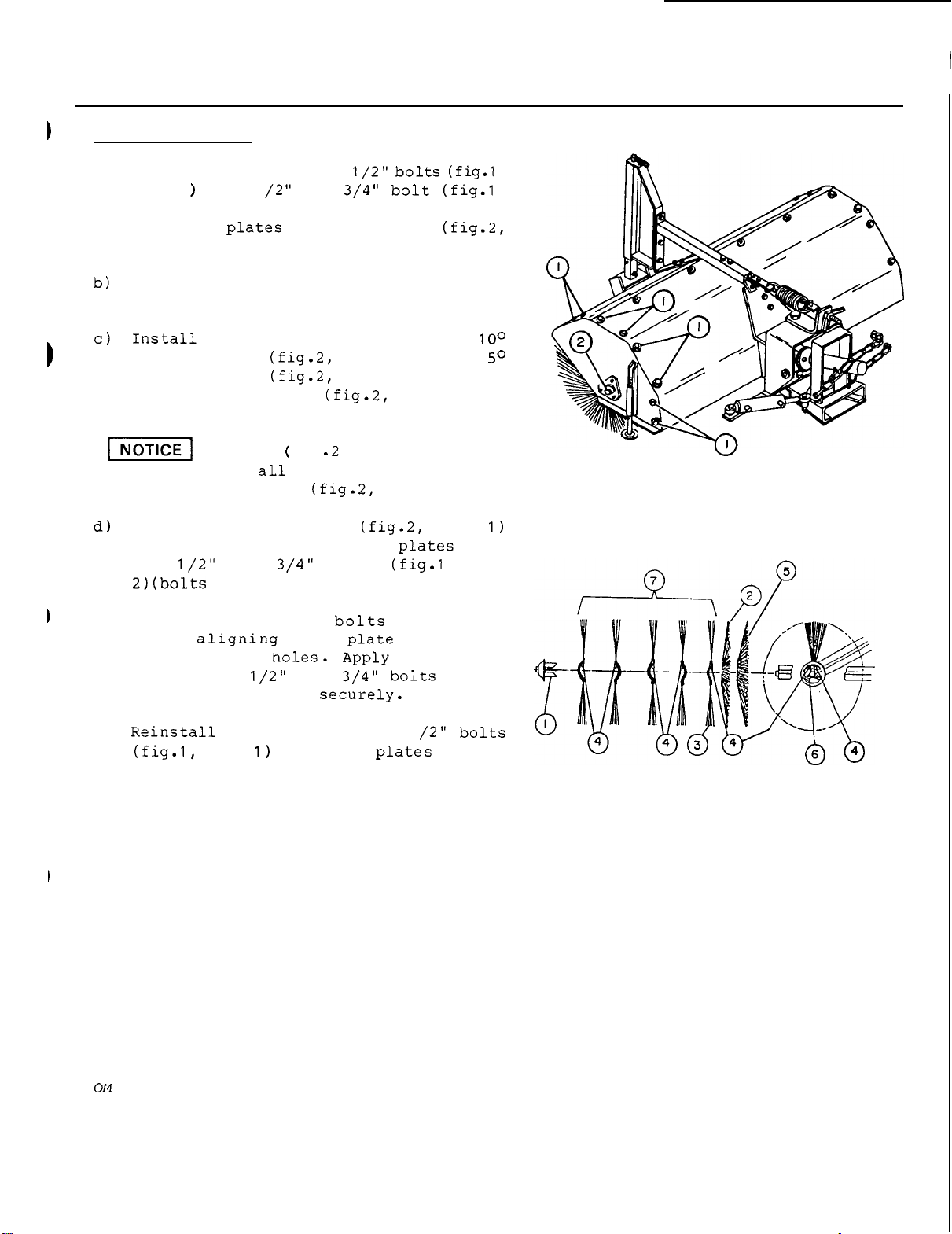
MAINTENANCE
-
BROOM
BRUSH
a)
I
REPLACEMENT
Remove
item
item
broom side
item
outward.
concave brush (fig.2,
concave brush (fig.2,
the
each
brushes must
brush support cone (fig.2,
on inside surface of side
the
the
eight 5/16
1
,
one
2) from
1).
1
each
"
x
x
1
broom end and remove
and retainer cup (fig.2,
item
item
zigzag brushes (f ig.2,
side of gearbox.
The
pins
x
fig -2
be placed on
1
,
item
with
5)
2)
item
4) in zigzag
a
the
and then
7)
the
item
6).
item
,
,
,
a
on
same
with
item
FIGURE
1
head and two flatwashers under
lockwasher). Thread bolts into shaft
ends,
broom
compound on
shaft ends. Tighten
e)
housing holes. Apply anti-seize
the
item
side of broom. Tighten securely.
side
1
eight 5/16
into side
"
x
holes
1
the
with
on each
FIGURE
2
07
79
35
Page 38
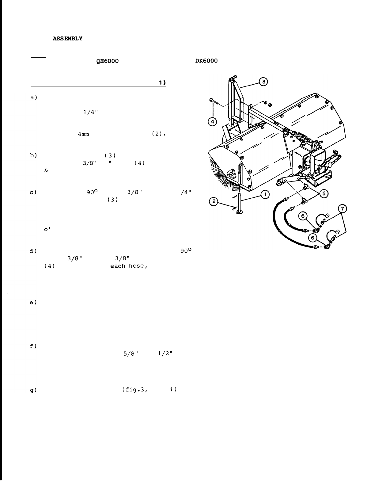
BROOM
-
NOTE:
STEP
Before mounting
with
1
Insert a parking stand
support from
5/32" x
of
in
with
Assemble jack
using
nuts. Tighten securely. Inflate front
tire
Install
pivoting female
port
ports facing you and
left,
clock.
an
FITA
:
BROOM
each
most
two 4mm x 80mm hairpins
PREPARATION (FIGURE
1
parking stand. Set parking stands
extended position and secure
three
to
30
psi.
a
using thread sealant.
set
both elbows
this
attachment on your tractor, your tractor must
subframe and an
(1)
in each stand
the
underside and install
cotter
1
elbow 3/8"
pin in upper hole
to front of broom
bolts
,
lockwashers
male
in each cylinder
With
base
at
end
approximately 2
FITA
x
1
cylinder
to
your
be
mounted
drive kit.
a
Using
elbow
a
male
over
on elbow before installation).
Attach
elbow
end elbow. Route
down pressure adjustment spring.
Install cylinder
female
and
from brushes)
bracket
Check pivot lock pin
make sure
to
and
OM
01
79
thread
at
one end of
quick
each
a
adapter
the
and
hitch
uni-torque nut (place ports away
with
it
avoid buckling of female hitch
to
facilitate quick
sealant, install
male
51" hose
the
x 3/8" pivoting female
coupler
(5)
(dust
to
46
"
hose
the
two hoses
base
using
.
Attach
other bolt and nut.
is
in
end on
a
its
innermost position
a
and install
with
cap
cylinder base end
to
x
rod end
dust
ring must be
cylinder rod
under
top
3
to
item
side
bolt
broom
cap
the
of
and
member
hitch
attachment.
36
FIGURE
1
,
Page 39
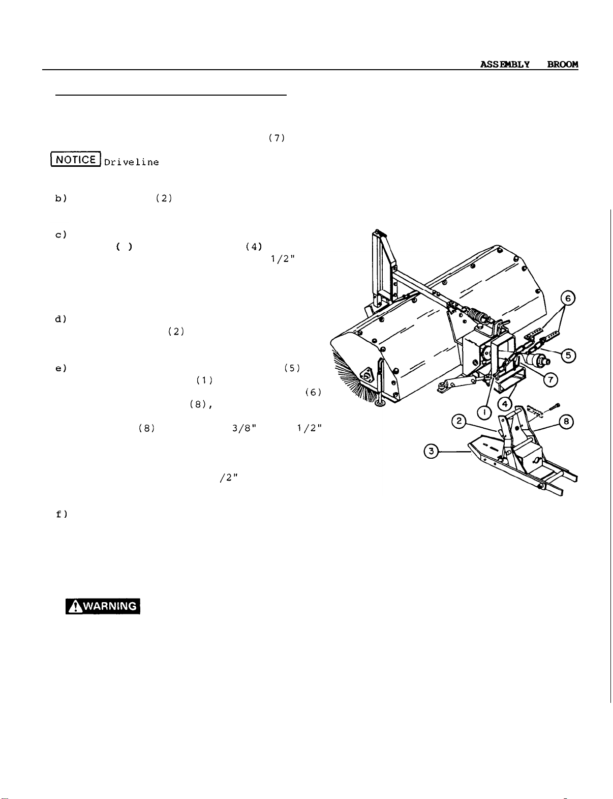
-
STEP
a)
2:
BROOM
Insert driveline half
yoke) over broom driveline half.
driveline on driveline support (7)
greased.
Place lever
in unlocked position.
Carefully drive
hitch'
Raise
ground, turn off engine and
parking brake.
Lock
male
placing lever
quick
Attach
broom female
cotter
using
hairpins.
subframe
bolts and nylon lock nuts. Select chain
support hole position
hitch
male
hitch
INSTALLATION (FIGURE
(with
on
male
tractor
3 into female
broom approximately 3 1/2" off
hitch
quick connect
hitch,
and introduce male
set
hitch
hitch
depth limiting chains
pins, and
the
clevis
is
lowered and supported by
to
broom female
fully forward. Secure
latch
hitch
Attach
with
linchpin.
using clevis
to
chain supports
drilled pins and
chains
using two 3/8" x
so
is
3
"
to
3
1
supports
that
2)
Set
rearward
on broom.
tractor
hitch
with
1
when
male
chain,
by
to
to
Holding
support forward and out of
connect driveline to subframe
Make sure locking collar on driveline
yoke
secured to shaft.
RPM.
shaft
the attachment end
the driveline can fly
force
or
death.
OM
01
79 37
the
driveline, rotate driveline
has
snapped back fully and
This
If
the
at
subframe end,
capable
shaft turns
collar
is
of
causing serious injury
is
not secured properly,
the
PTO
at
not locked
or
if
the yoke
loose
with
way, and
shaft.
is
well
very high
to
the
at
great
FIGURE
2
Page 40
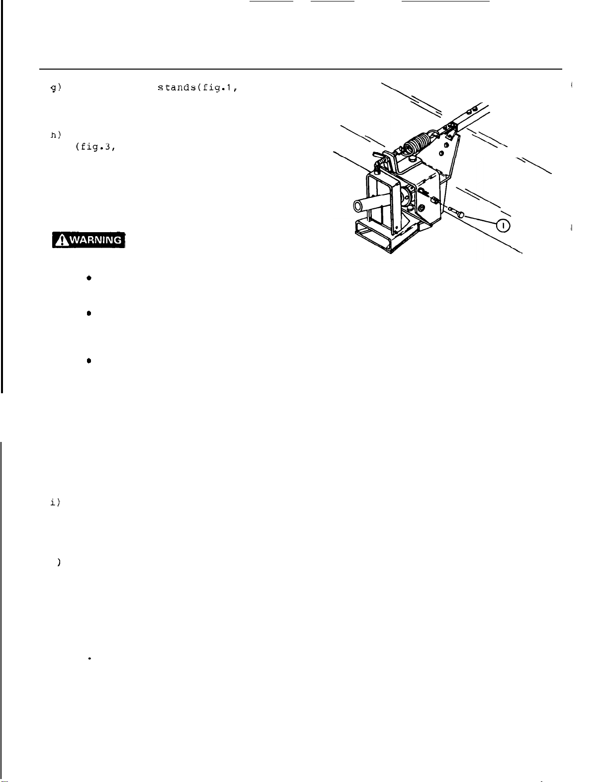
BROOM
-
ASSEMBLY
item
raised position, placing hair pin on
upper
Unlock broom pivot
position;
down on broom head
(this allows broom to follow ground vari
ations).
during transport.
side of stand support.
bracket
item
a
1)
light
in
its
pressure
will
This
bracket should remain unlocked
by
most extended
help
pin adjustment
placing pin
either
Escaping hydraulic fluid
under pressure can penetrate
the
causing serious injury.
Do
not use your hands
leaks.
paper
Stop
Use
to
search
engine
a
piece
for leaks.
and
relieve pressure by
moving valve handles back
before connecting
to
of
cardboard
or
disconnecting
check
and
lines.
Tighten
engine
If
any fluid
may result in gangrene
surgically removed within
doctor
familiar
all
connections
or
pressurizing lines.
is
injected into
if
the
a
with
this
form
before
the
fluid
few
hours by
of injury.
starting
skin,
is
1)
up
(oil)
skin
for
forth
not
in
or
-
or
it
a
FIGURE
\.
\
3
NOTE:
j
k) Correct
OM
If
hydraulic
with
identified
attachment hoses to matching color female
couplers on right hand side
Connect
female quick coupler on right hand side
of tractor and rod end hose to upper
female quick coupler.
Verify operation
,
(if not
hydraulic
location) then identify hydraulic hoses
in relation to female couplers using
colored rings.
32
0179
colored plastic rings, connect
cylinder base end hose
of
as
described, stop engine, release
pressure
all
adjustment settings on page
hoses are already
of
tractor.
to
broom angling described
and
switch
coupler
lower
the
38
Page 41
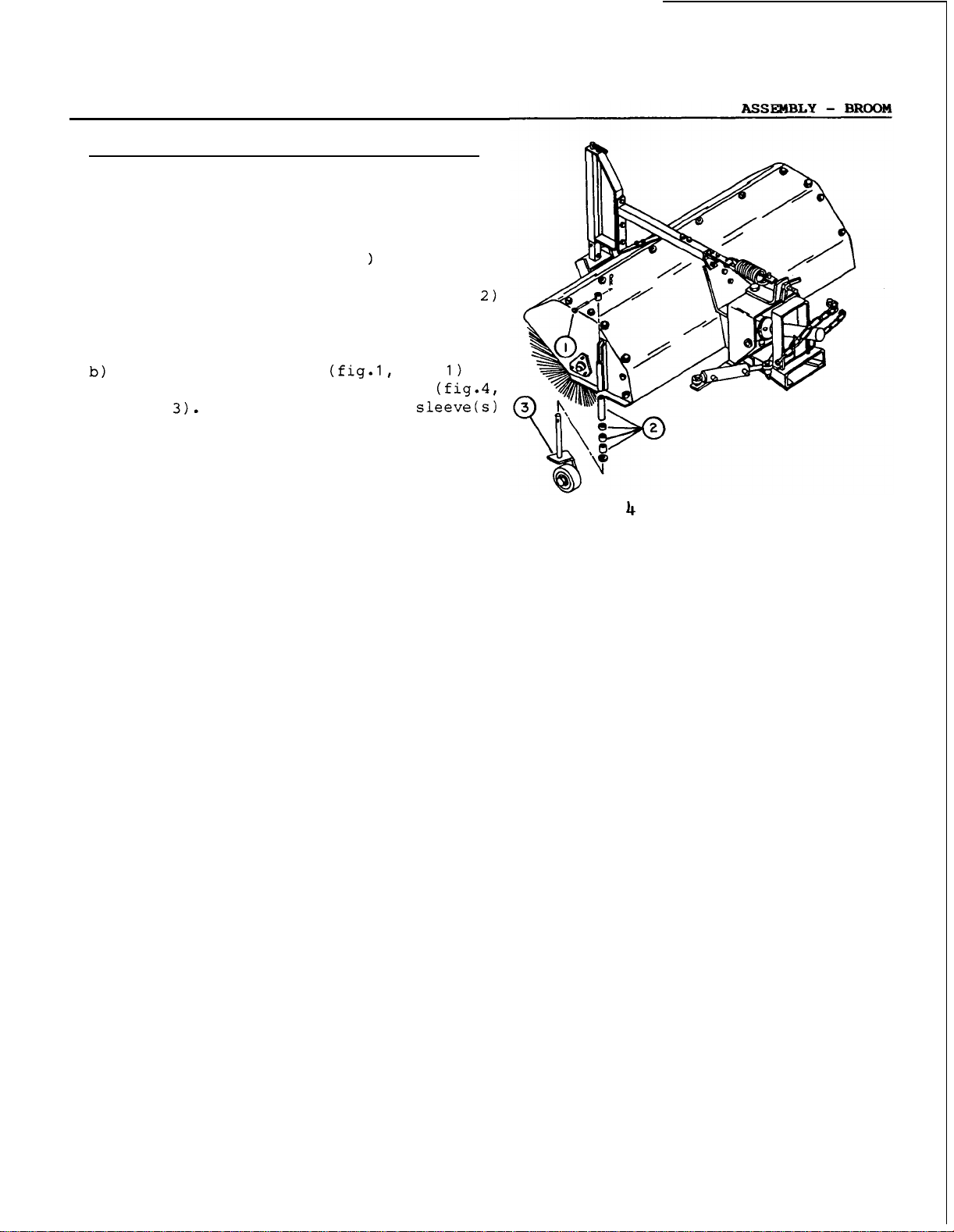
STEP
3:
OPTIONAL CASTER
WHEEL
INSTALLATION
NOTE:
a)
Remove pin (fig .4,
from
number of
to remain on bottom portion of
wheels.
replace
item
over
supports, and
pins (fig.4,
Caster
thatching and to prevent gouging
(refer to applications page 33).
wheels
are
item
each
caster
caster
spacer
them
with
Place remaining spacer sleeve(s1
wheels
wheel.
sleeves (fig.4,
the
caster
on upper side of stand
secure
item
1)
caster
and
required for lawn
1
and hair pin
Select desired
item
caster
item
and
wheels
hair
wheels
pins.
with
FIGURE
OM
0179
39
Page 42

DISMOUNTING
Extend broom parking stands (fig.1,
placing
stands supports, and lock broom attachment
using pin
either
help setting pin in innermost (or lock)
position)
and remounting.
Disconnect chains
chain supports (fig
hair
pin from clevis.
Set hydraulic valve
turn engine off
ignition key and relieve hydraulic
by moving valve handles back and forth.
Disconnect angling cylinder hoses from
tractor.
Remove lynch pin from
and
place
in unlock position (rearward)
up
.
This
male
hair
or
pins on underside of
item
1
(a
down on broom head
is
to
facilitate dismounting
item
in
float position,
,
set
parking brake, remove
male
hitch
lever (fig.2,
light pressure
item
6
by removing
hitch
item
will
from
pressure
latch
item
.
Disconnect driveline from tractor
place
Carefully
it
driveline on
separate
rests
on storage stands.
its
support.
broom from tractor
PTO
and
as
OM
01
79
40
Page 43
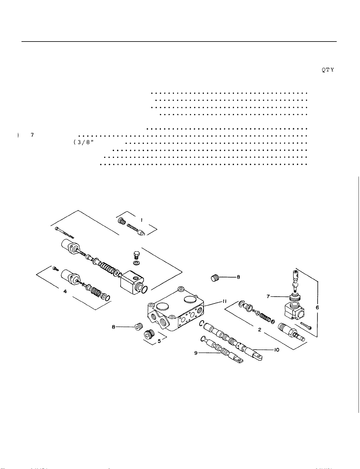
TWO
SPOOL
........................................................................
........................................................................
REF
........................................................................
........................................................................
VALVE
ASSEMBLY
DESCRIPTION
PARTS
GUIDE
1
2
3
4
5
6
8
9
10
11
Check valve repair
kit
Relief valve repair
Float
spool
repair
kit
Regular spool repair
AET
Plug
...................................................
Lever pivot box ass'y
Boots
Plug
NPTF)
Regular spool
Float spool
Valve body
3
\
kit
kit
..
1
1
1
1
1
2
2
2
1
1
1
OM
0179
41
Page 44
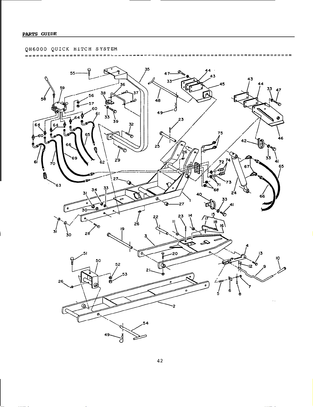
OM
0179
Page 45
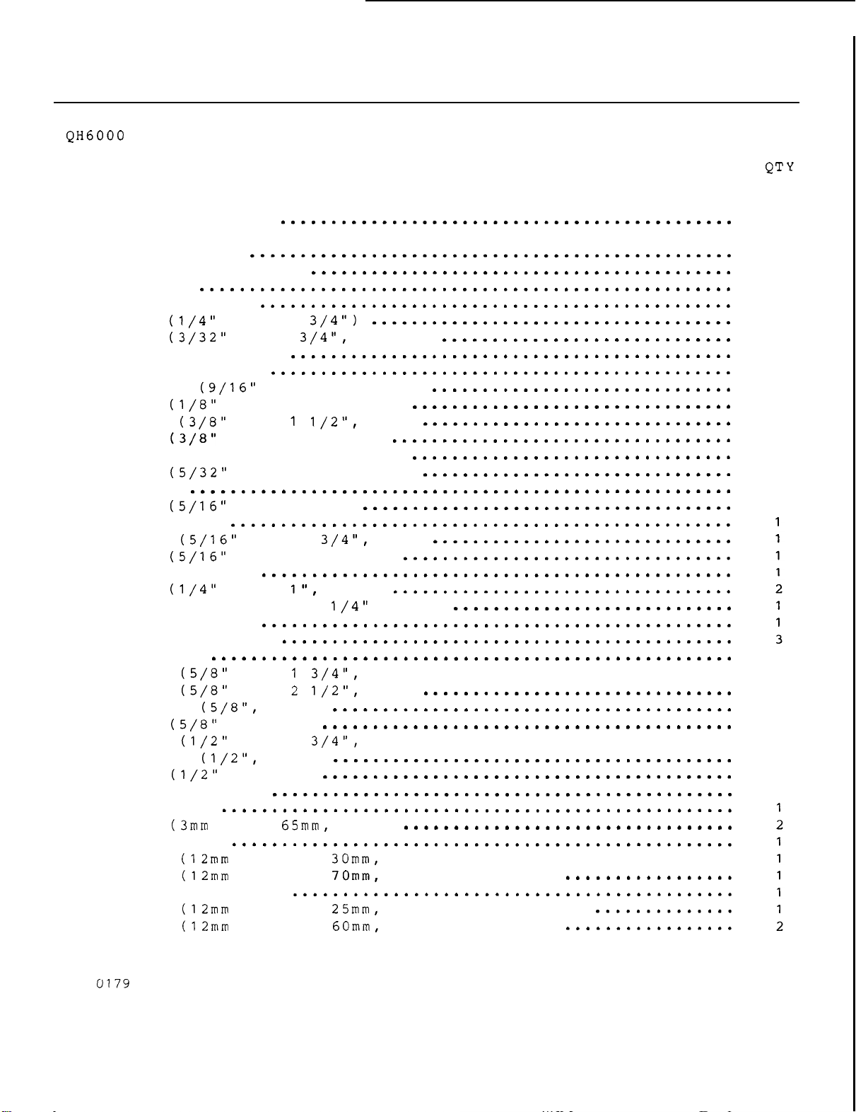
PARTS
GUIDE
........................................................................
........................................................................
REF
........................................................................
........................................................................
1
2
3
4
5
6
7
8
9
10
11
12
13
14
15
16
17
18
19
20
21
22
23
24
25
26
27
28
29
30
31
32
33
34
35
36
37
38
39
40
41
QUICK
Front subframe
Rear
Quick
Quick
Spring
Spring
Pin (1/4" dia x
Pin (3/32"
Attaching lever
Rubber handle
subframe
Washer
Pin (1/8" dia x
Bolt
Nut (3/8"
Safety chain and pins ass'y
Pin (5/32" dia x 1".
Chain
Pin (5/16" dia. linch)
Pivot pin
Bolt
Nut (5/16"
Cylinder pin
Pin (1/4"
Cylinder 2
Cylinder pin
Grease
Bushing
Bolt
Bolt
Washer
Nut
Bolt
Washer
Nut
Valve support
Link pin
Pin (3mm dia x 65mm.
L-bracket
Bolt
Bolt (12mm x 1.25 x
Hose
Bolt (12mm x 1.25 x 25mm. hex) without loader
Bolt
HITCH SYSTEM
hitch
hitch
latch
plate
dia
NC
NC.
NC
NC.
dia
"
dia x 6
fitting
NC
NC
NC.
NC
NC.
guard
L.H.
DESCRIPTION
..............................................
1
x
dia
hole. flat)
1".
X
nylon lock)
cotter)
cotter)
cotter)
x
1 3/4". hex)
nylon lock)
x
x
X
lock)
hex)
x
hex)
roll)
...............................
1
hair)
...............................
..............
hex)
with
with
loader
loader
1
1
1
1
1
1
1
1
1
1
1
2
1
1
1
1
1
1
2
3
1
4
4
1
11
1
1
OM
43
Page 46
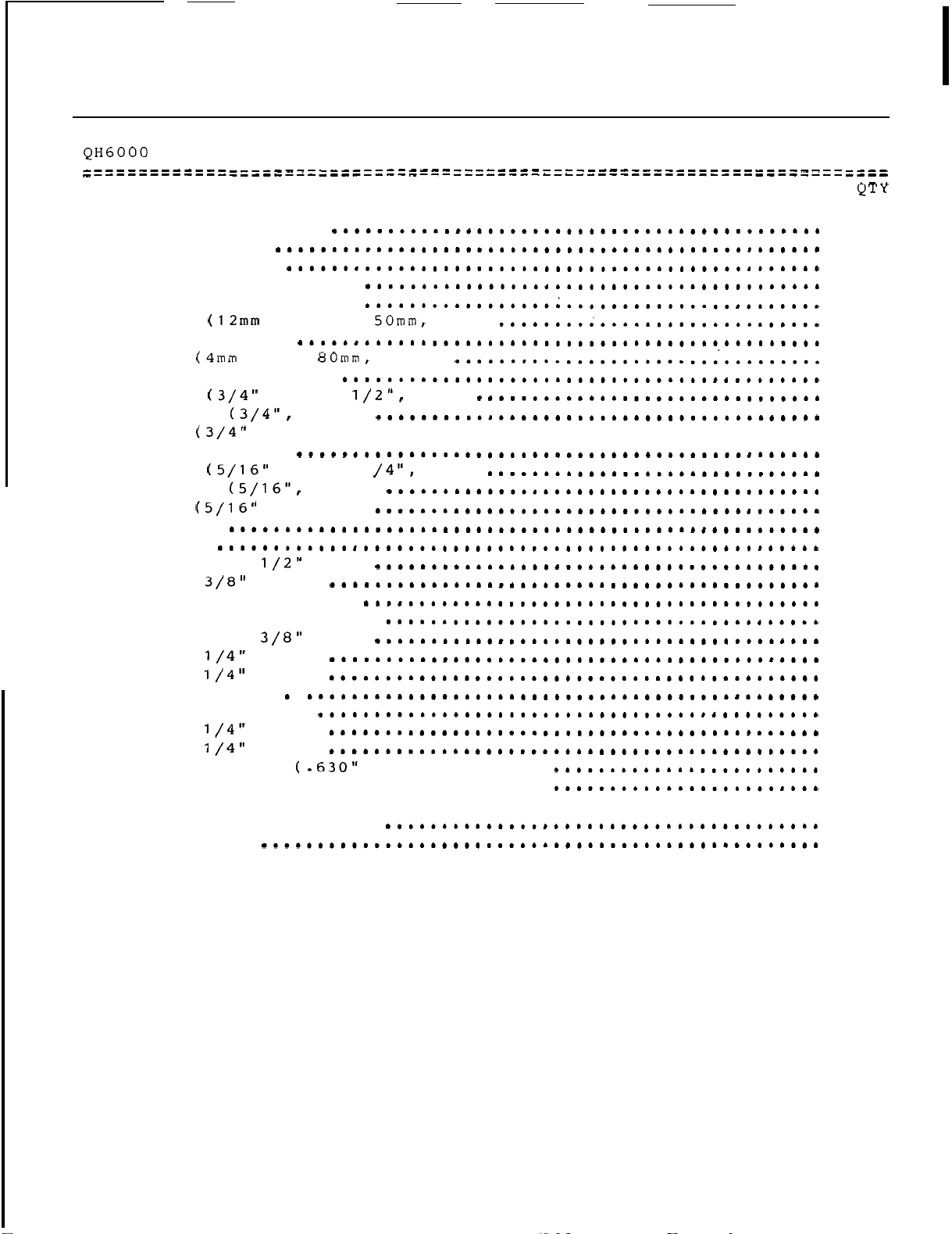
PARTS
GUIDE
QUICK
REF
........................................................................
........................................................................
42
43
44
45
46
47
48
49
50
51
52
53
54
55
56
57
58
59
60
61
62
63
64
65
66
67
68
69
70
71
72
73
74
75
Hose guard
Mower
Loader
Front bracket
Front bracket
Bolt
Fixation pin
Pin (4mm dia
Rear
Bolt
Washer
Nut
Fixation pin
Bolt
Washer
Nut
Handle
Valve
Connector
Hose
Male
Female quick coupler
Connector
Hose
Hose
Elbow
Rubber grommet
Hose
Hose
Nylon
Green
Yellow
Female
Dust plug
HITCH
SYSTEM
R.H.
shim
shim
L.H.
R.H.
x
1.25
x
hitch
plate
NC
x
3 1/2".
lock)
NC.
hex)
NC
x
lock)
NC.
hex)
male
x
30
"
quick coupler
male
x
76
"
x
78
"
90
deg
x
62
"
x
64
"
washer
plastic
plastic
quick
ring (identification)
ring (identification)
coupler
DESCRIPTION QTY
x 50mm. hex)
hair)
hex)
.........................................
2 1 /4".
dia
hex)
hole.
flat)
.......................
1
2
2
1
1
7
1
2
1
1
1
1
1
3
3
3
2
1
2
2
1
1
4
1
1
2
2
1
1
2
1
1
2
2
OM
0179
44
Page 47
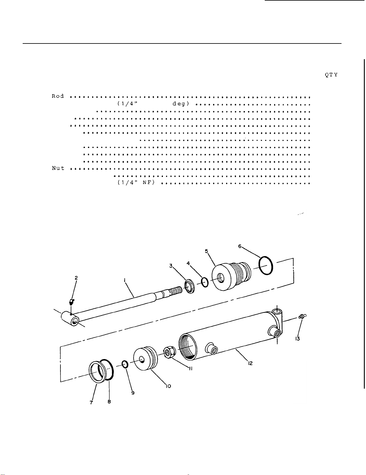
PARTS
GUIDE
HYDRAULIC
........................................................................
........................................................................
LIFT
CYLINDER
REF DESCRIPTION
........................................................................
........................................................................
1
2
3
4
5
6
7
8
9
10
11
12
13
Grease
Rod
fitting
wiper
Seal
Cap
0-Ring
Tefflon piston ring
0-Ring
0-Ring
Piston
Cylinder tube
Grease
fitting
NP.
90
1
1
1
1
1
1
1
1
1
1
1
1
1
OM
0779
45
Page 48
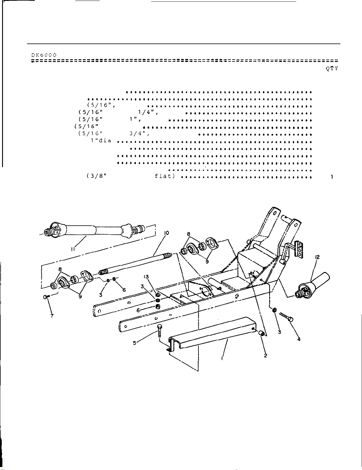
PARTS
GUIDE
REF
........................................................................
........................................................................
........................
DESCRIPTION
1
2
3
4
5
6
7
8
9
10
11
12
13
Driveline guard
Spacer
Washer
Bolt
Bolt
Nut
Bolt
lock)
NC
x
1
NC
NC.
x
hex)
hex)
x 3/4". carriage)
Bearing 1"dia
Bearing retainer
Splined shaft
Mid
driveline
Driveline front male half
Washer
dia
hole.
hex)
1
1
6
1
1
5
4
2
4
1
1
1
OM
0179
46
Page 49
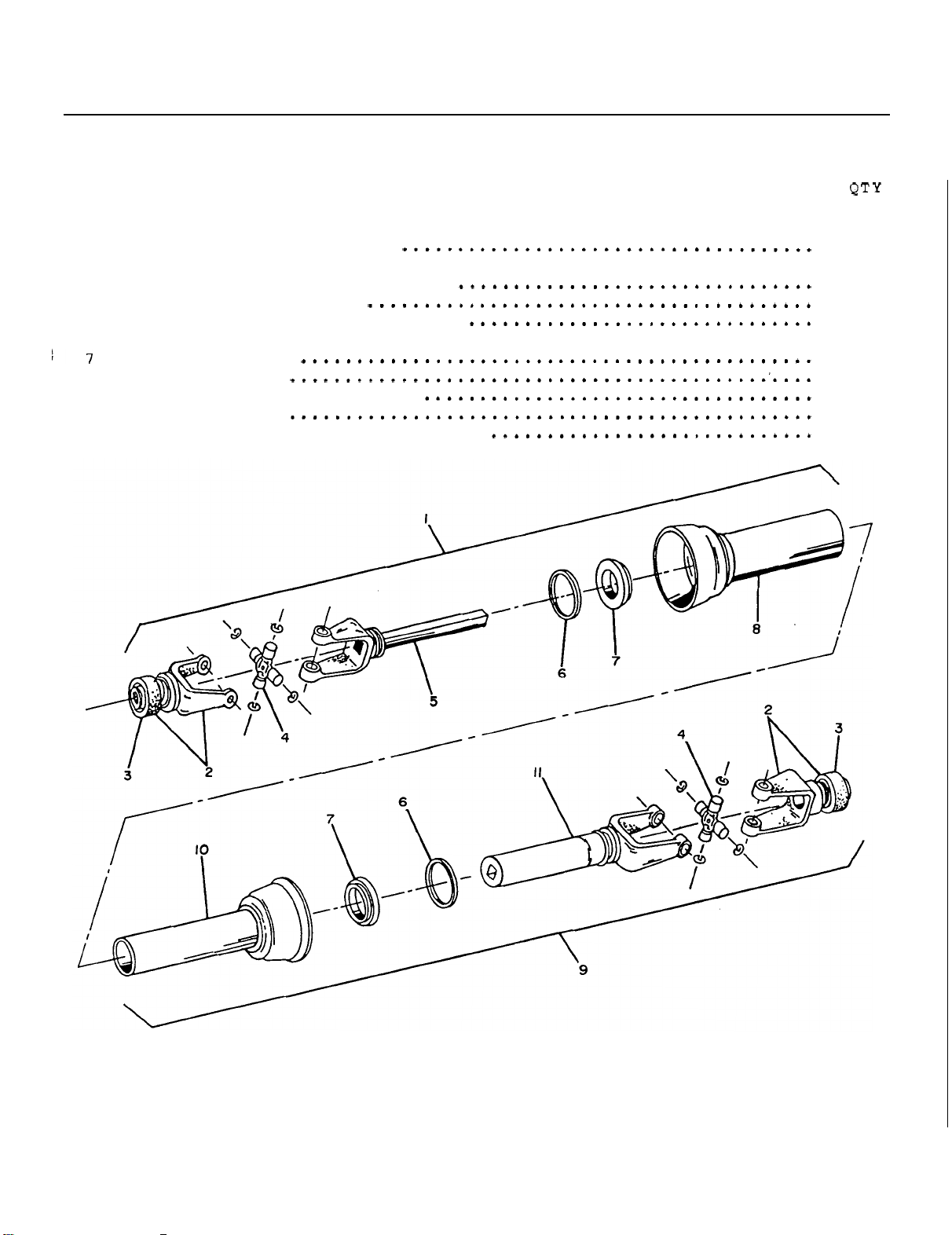
PARTS
MID
DRIVELINE
........................................................................
........................................................................
REF DESCRIPTION QT
........................................................................
........................................................................
GUIDE
1
2
3
4
5
6
8
9
10
11
Driveline
Quick disconnect yoke assembly
Spring lock yoke
Universal joint kit
Yoke and
Bearing retainer
Nylon bearing
Outer
Driveline
Inner shield
Yoke and female shaft assembly
male
male
shield
female
portion
repair
shaft assembly
kit
...........................................
portion
(15
splines)
................
1
2
2
2
1
2
2
1
1
1
1
OM
0179
47
Page 50
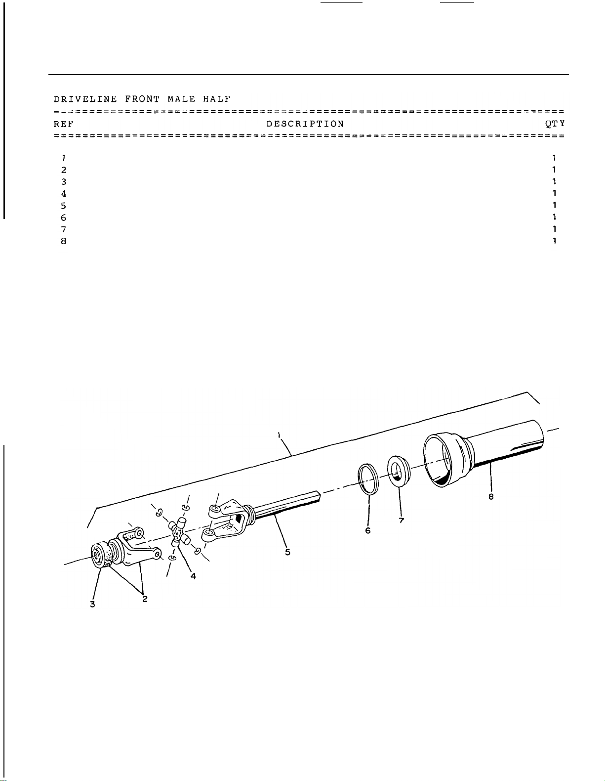
PARTS
GUIDE
Driveline male portion assembly
Quick disconnect yoke assembly
Spring lock yoke
Universal joint kit
Yoke and
Bearing retainer
Nylon bearing
Outer
male
shield
repair
kit
................................
........................................
shaft assembly
...............................
...........................................
..............................................
...............................................
............................
(15
splines)
................
OM
0179
48
Page 51
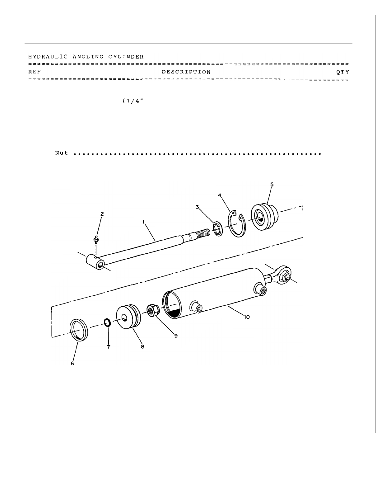
PARTS
GUIDE
1
2
3
4
5
6
7
8
9
10
Rod
Grease
Rod
Snap ring
Cap
u
0-Ring
Piston
Cylinder
Seal kit
........................................................
fitting
wiper
........................................................
cup
......................................................
.....................................................
.....................................................
NF)
...................................
..................................................
..................................................
tube
..............................................
...................................................
1
1
1
1
1
1
1
1
1
1
OM
0179
49
Page 52
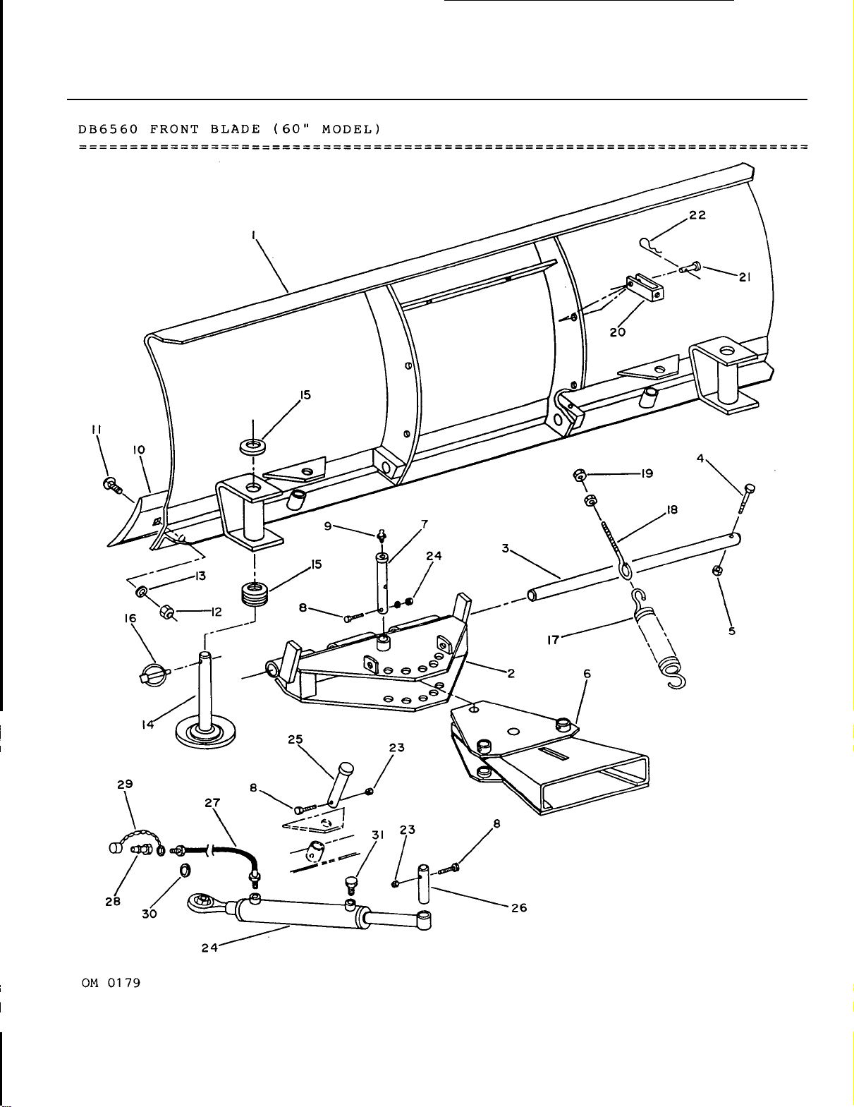
PARTS
GUIDE
50
Page 53
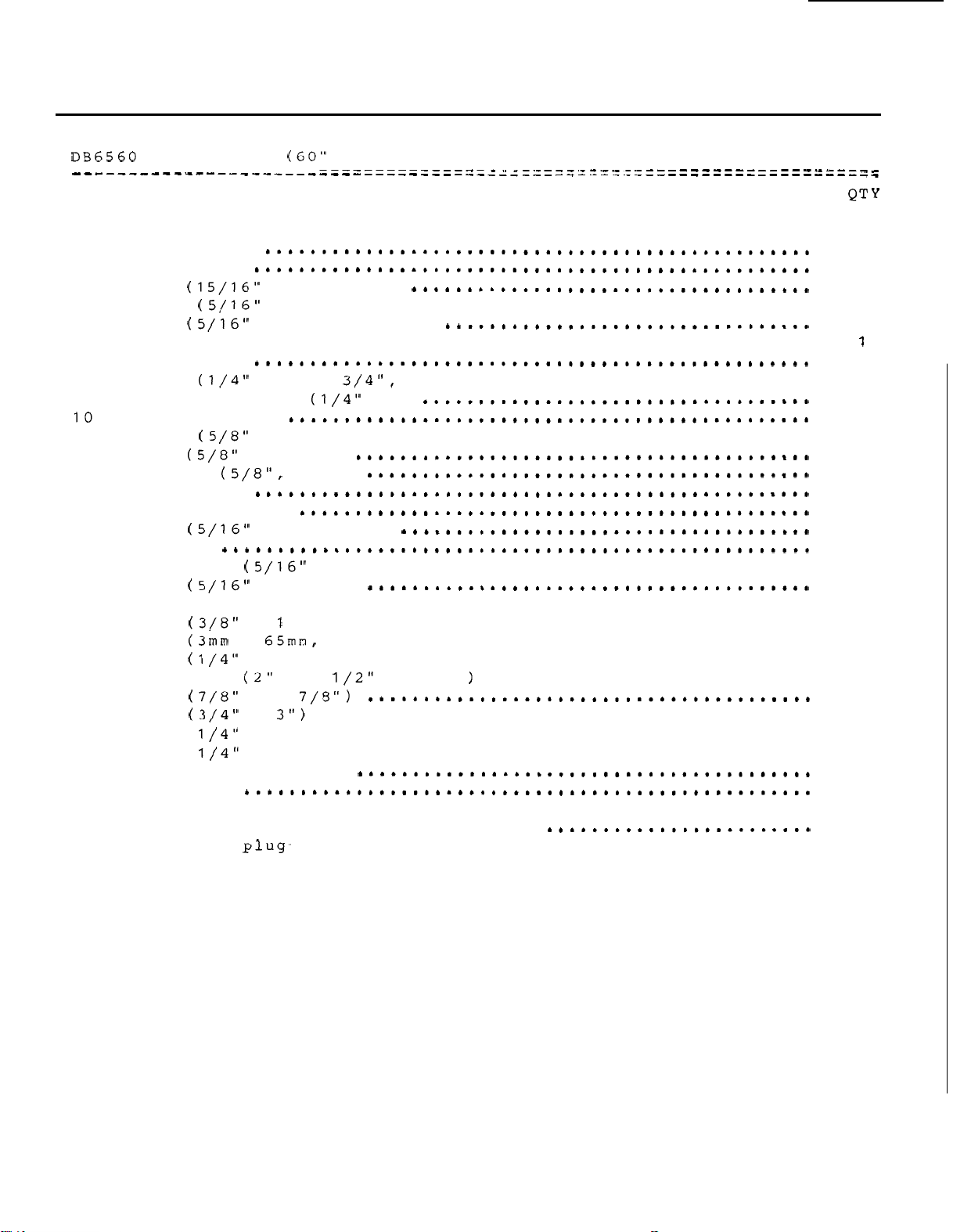
PARTS
GUIDE
.....................................
REF DESCRIPTION
........................................................................
........................................................................
1
2
3
4
5
6
7
8
9
11
12
13
14
15
16
17
18
19
20
21
22
23
24
25
26
27
28
29
30
31
Mold board
Hitch
Rod (15/16"
Bolt
Nut
Female quick hitch
Pivot pin
Bolt
Grease
Cutting edge
Bolt
Nut (5/8"
Washer (5/8". lock)
Skid shoe
Spacer
Pin (5/16"
Spring
Eye
Nut
Trip spring lockout bracket
Pin (3/8"
Pin (3mm
Nut
Cylinder
Pin (7/8"
Pin
Hose
Hose
Quick coupler
Dust
Yellow
Green
Breather plug-
BLADE
box
x
NC
NC.
NC
fitting (1/4" NF)
NC
NC.
washer
dia.
bolt
NC.
x
x
NC.
x
x
2
x
x
41
x
48
cap
plastic
plastic
MODEL)
19 5/16")
x 2".
nylon lock)
hex)
..................................
.........................................
x
1
x
2".
hex)
linch)
NC
hex)
plow)
x
5" with hex . nut)
...............................
..................................
................................
7/16")
nylon lock)
6 1/2" stroke.
.......................................
hair)
.....................................
..................................
.............................
............................................
"
............................................
"
............................................
male
ring (identification)
ring (identification)
..............................................
......................
.......................
1
1
1
1
1
1
5
1
1
7
7
7
2
12
2
2
2
2
2
2
2
5
2
2
2
1
1
2
2
2
2
2
OM
0179
51
Page 54
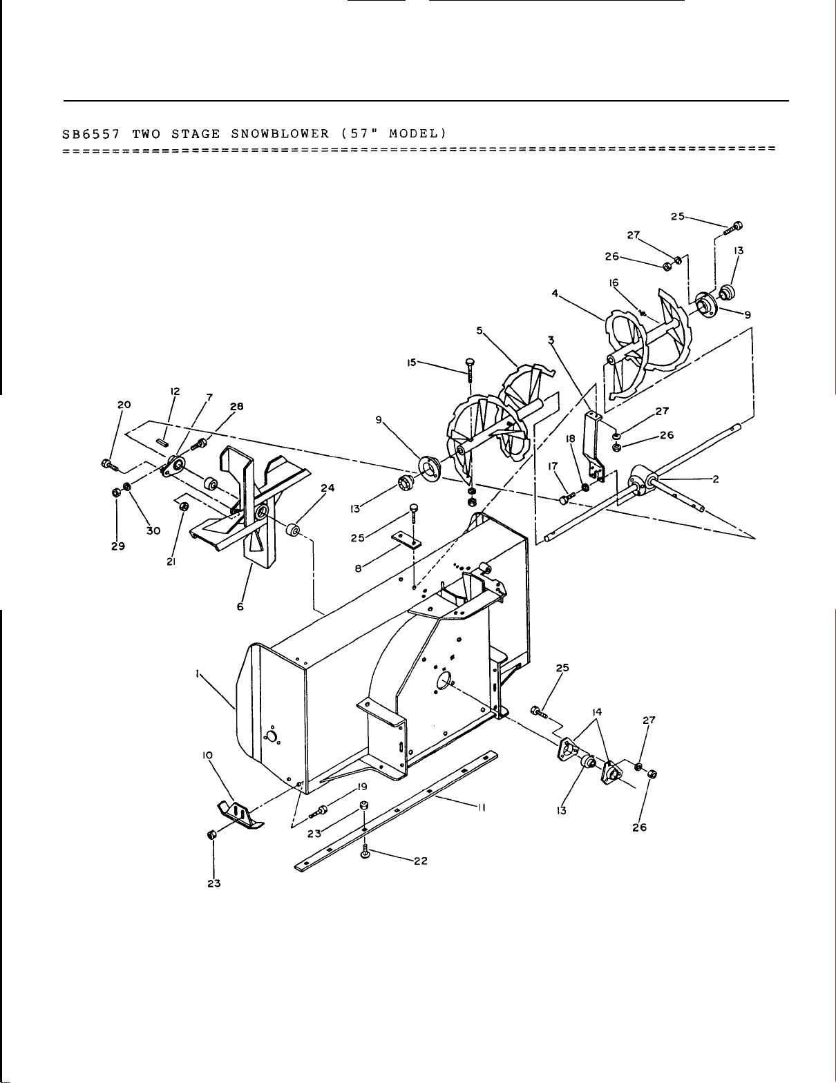
PARTS
GUIDE
OM
0179
52
Page 55
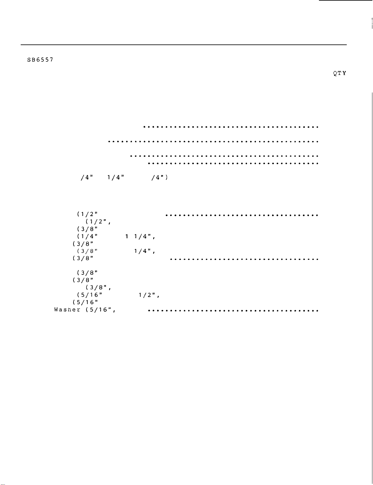
PARTS
GUIDE
........................................................................
........................................................................
REF
........................................................................
........................................................................
1
2
3
4
5
6
17
8
9
10
11
12
13
14
15
16
17
18
19
20
21
22
23
24
25
26
27
28
29
30
TWO STAGE SNOWBLOWER
Housing
Gear
Gear
Auger
Auger assembly L.H.
Fan
Shear
Reinforcement bracket
Bearing
Adjustable skid shoe
Cutting edge
Key
Bearing
Bearing
Bolt (shear. lockwasher and nut)
Grease
Bolt
Washer
Bolt
Bolt
Nut
Bolt
Nut
Bushing (oil-lite)
Bolt
Nut
Washer
Bolt
Nut
(57
"
MODEL)
DESCRIPTION QT
....................................................
box assembly
box support bracket
assembly
..........................................
...................................
R.H.
........................................
........................................................
plate
......................................
retainer
...............................................
(1
x
with locking collar
retainer
fitting
NC
NC
NC
NC.
NC
NC.
x
1
1
...........................................
.............................................
X
1".
hex)
lock)
x
x
nylon lock)
x
nylon lock)
........................................
1".
carriage)
hex)
1
plow)
.........................................
NC
x
1".
hex)
NC.
NC
NC.
hex)
lock)
x
hex)
.........................................
........................................
2 1/2".
........................................
lock)
.................................
................................
...........................
..............................
...............................
...................................
..............................
...................................
hex)
..............................
1
1
1
1
1
1
1
1
2
2
1
1
3
2
2
2
4
4
4
1
1
7
11
2
11
11
11
1
1
1
OM
0179
53
Page 56
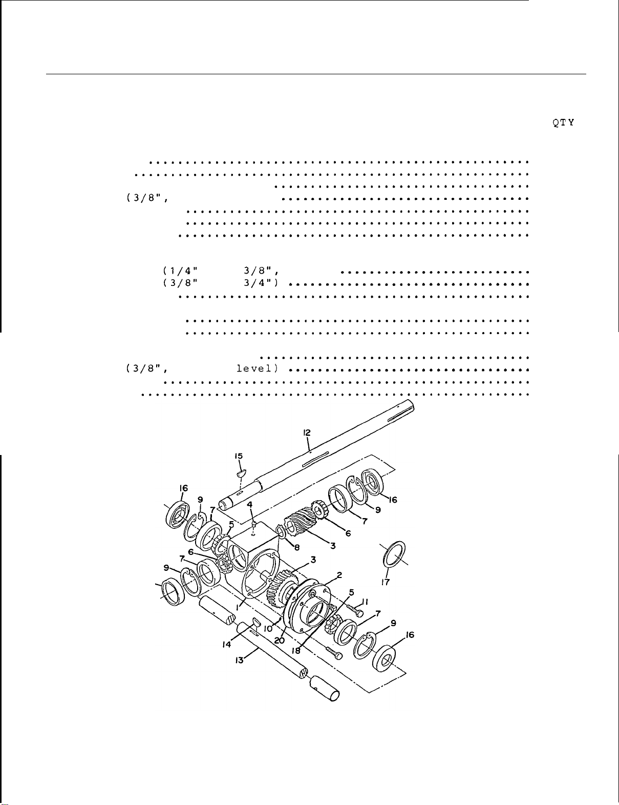
PARTS
GUIDE
WORM
........................................................................
........................................................................
REF
........................................................................
........................................................................
10
11
12
13
14
15
16
17
18
19
20
GEAR
1
2
3
4
5
6
7
8
9
BOX
Housing
Cover
Worm
Plug
Bearing cone
Bearing cone
Bearing cup
External retraining ring
Internal retraining ring
Set
Cap
Input shaft
Output shaft
Key woodruff
Key woodruff
Seal
Shim (use
Plug
Input
Gasket
and bronze gear
screw
screw
.......................................................
cap
DESCRIPTION
set
NPT. vent)
...................................
...................................
NF
NC
x
x
allen)
...............................................
as
required)
NPT.
1
1
1
1
2
2
4
1
4
1
4
1
1
1
1
3
.
1
1
1
OM
0179
I9
.
54
Page 57
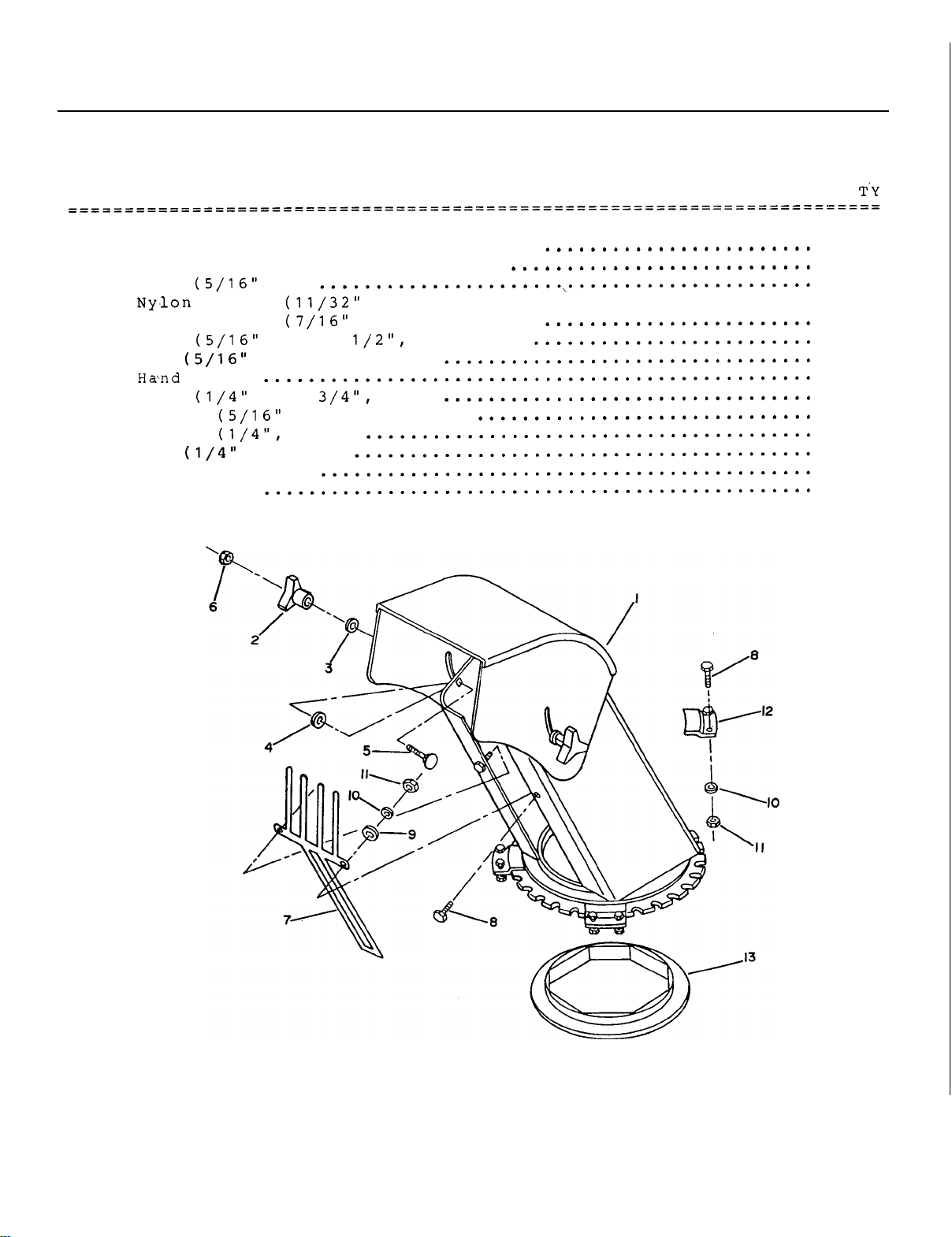
PARTS
GUIDE
CHUTE
........................................................................
........................................................................
REF DESCRIPTION
1
2
3
4
5
6
7
8
9
10
11
12
13
WITH
Chute
Chute
Knob (5/16"
DEFLECTOR
with
with
knob and decals
knob and decals (USA)
NC)
washer
Nylon
Bolt
Nut (5/16"
Bolt (1/4"
Washer
washer
NC
NC.
NC
Washer
Nut (1/4"
Retaining plate
Nylon ring
NC.
x
1
nylon lock)
x
hex)
hole.
hex)
(CANADA)
hole.
hole.
flat)
flat)
flat)
.......................
Q
1
1
2
2
2
2
2
1
10
2
10
10
4
1
OM
0179
55
Page 58
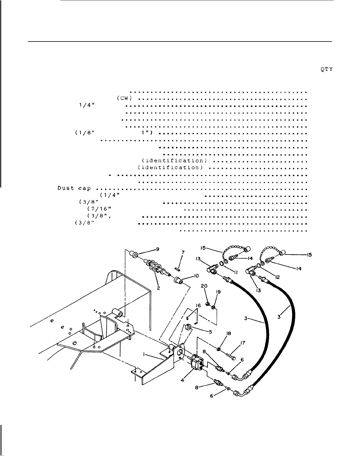
PARTS
GUIDE
HYDRAULIC
........................................................................
........................................................................
REF
........................................................................
........................................................................
1
2
3
4
5
6
7
8
9
10
11
12
13
14
15
16
17
18
19
20
Male
Set
Bolt
Washer
Washer
Nut
CHUTE
Rotation bracket
Rotation worm
Hose
Hydraulic motor
Locking collar
Flow
restrictor
Key
Connector
Plastic bushing
Plastic bushing
Yellow
Green
Elbow
quick coupler
screw
Seal kit for hydraulic motor
ROTATION
x
x
plastic
plastic
90
deg
NC.
DESCRIPTION
28
"
3/16
"
x
1
5/16
"
1
11/16
"
ring (identification)
ring (identification)
NC
x
5/16".
NC
x
1".
hex)
dia hole. flat)
lock)
hex)
allen)
1
1
2
1
1
2
1
2
1
1
1
1
2
2
2
2
2
2
2
2
OM
01
79
56
Page 59
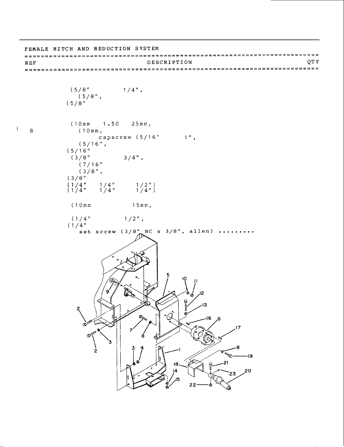
PARTS
GUIDE
1
2
3
4
5
6
7
9
10
11
12
13
14
15
16
17
18
19
20
21
22
23
Female hitch
Bolt
Washer (5/8". lock)
Nut (5/8"
Reduction
Reduction gear box
Bolt
Washer
Flat socket
Washer
Nut (5/16"
Bolt
Washer
Washer
Nut (3/8"
Key (1/4" x 1/4"
Key (1/4" x 1/4" x
Driveline guard
Bolt
Driveline female half
Bolt
Nut (1/4"
Socket
...............................................
NC
x
1
NC.
hex)
gear
NC.
NC.
box
x 1-50 x 25mm. hex)
NC.
NC
x 3 3/4".
dia
lock)
hex)
NC
x
nylon lock)
.........................................
support
.........................................
lock)
hex)
hole.
.........................................
x
2
1
............................................
2 1/2". hex)
...............................
........................................
.................................
.............................
........................................
NC
x
allen)
................
.......................................
........................................
hex)
flat)
...............................
..............................
........................................
.................................
.................................
.............................
......................................
...............................
..................................
..........
1
4
4
2
1
1
3
4
2
2
2
2
2
2
2
1
1
1
1
1
1
1
1
OM
0179
57
Page 60
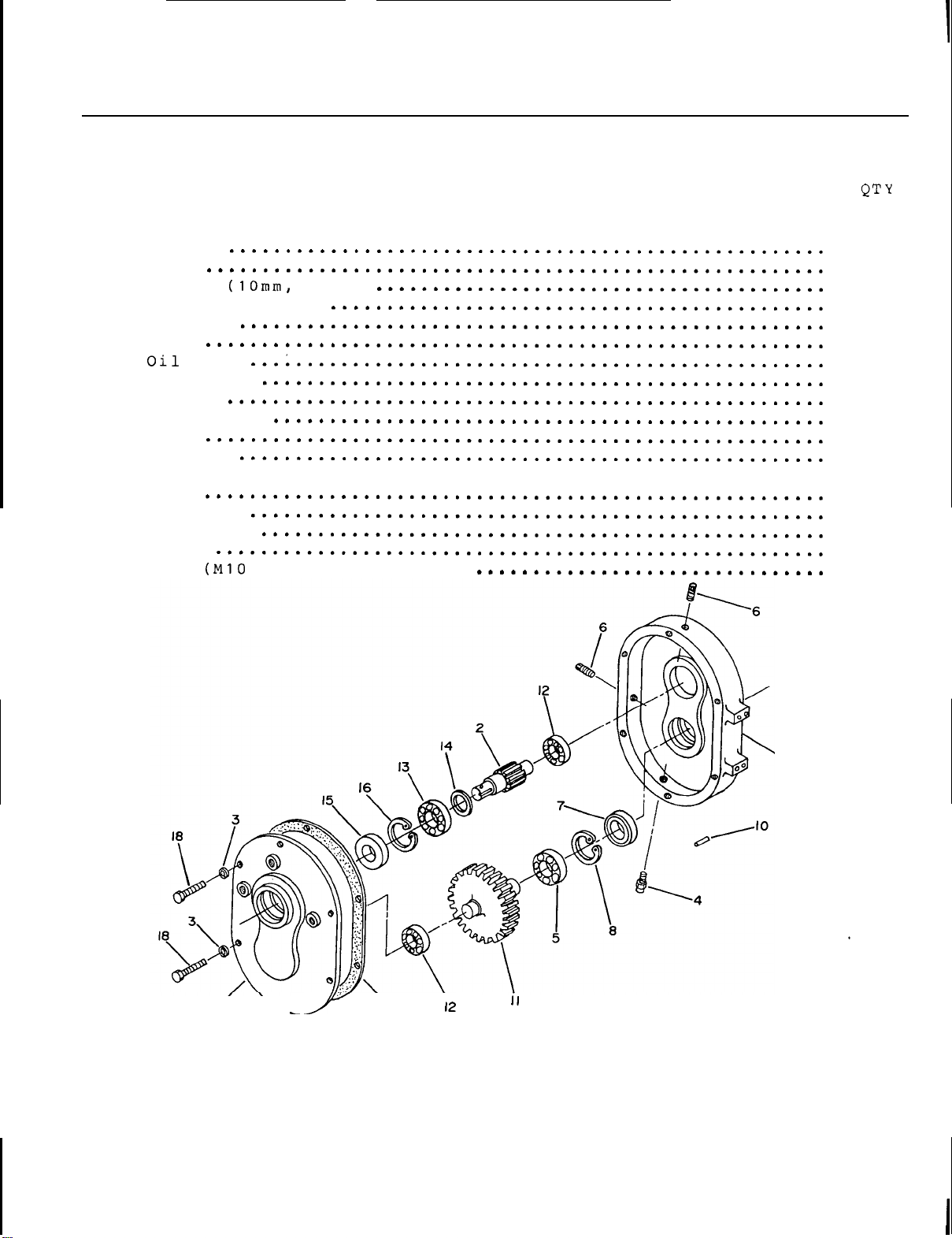
PARTS
GUIDE
REDUCTION
........................................................................
........................................................................
REF DESCRIPTION
........................................................................
........................................................................
1
2
3
4
5
6
7
8
9
10
11
12
13
14
15
16
17
18
Gear
Bearing
Bearing
Shim
Oil
Snap ring
Cover
Bolt
GEAR
Casing
Gear
Washer
Oil
filler plug
Bearing
Plug
seal
Snap ring
Gasket
Spring
pin
....................................................
seal
BOX
x
lock)
30mm
-
8.8.
hex)
1
1
6
1
1
2
1
1
1
2
1
2
1
1
1
1
1
6
OM
0179
\
‘I
\
58
Page 61
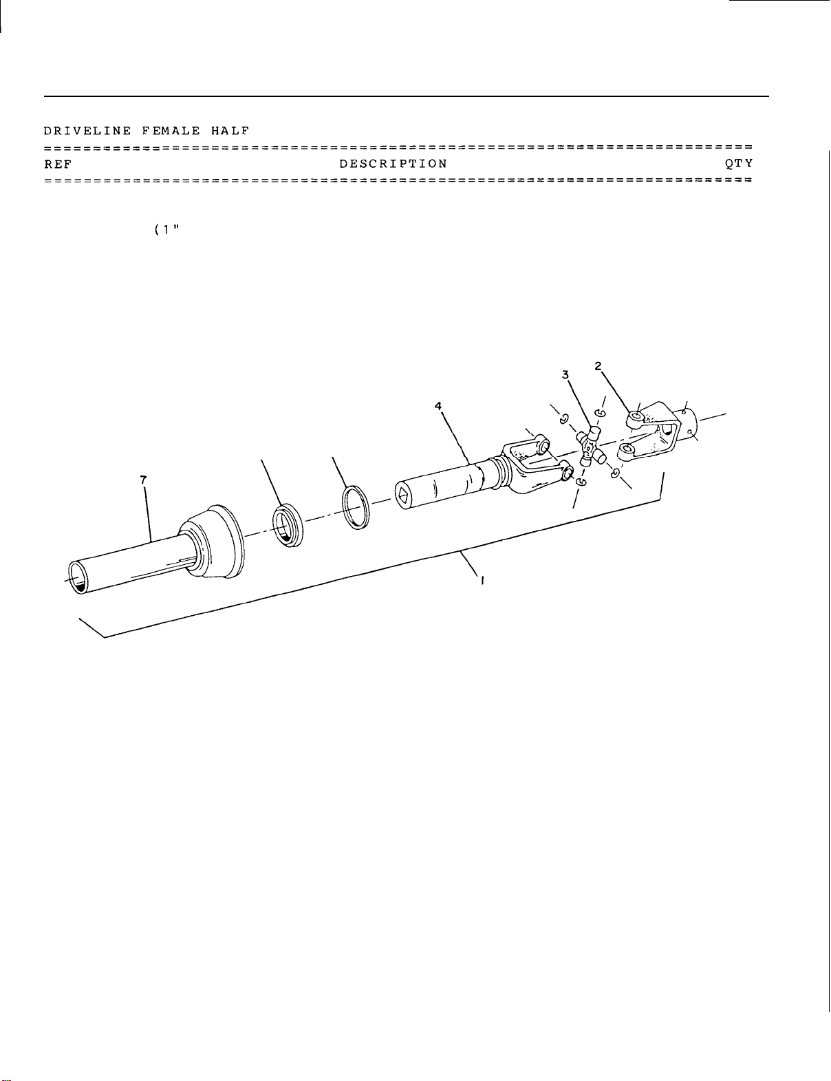
PARTS
GUIDE
1
2
3
4
5
6
7
Driveline female portion assembly
Yoke
Universal joint kit
Yoke and female shaft assembly
Bearing retainer
Nylon bearing
Inner
dia.
shield
hole)
........................................
........................................
.............................
...........................................
..............................................
...............................................
5
6
\
..........................
1
1
1
1
1
1
1
OM
01
79
59
Page 62
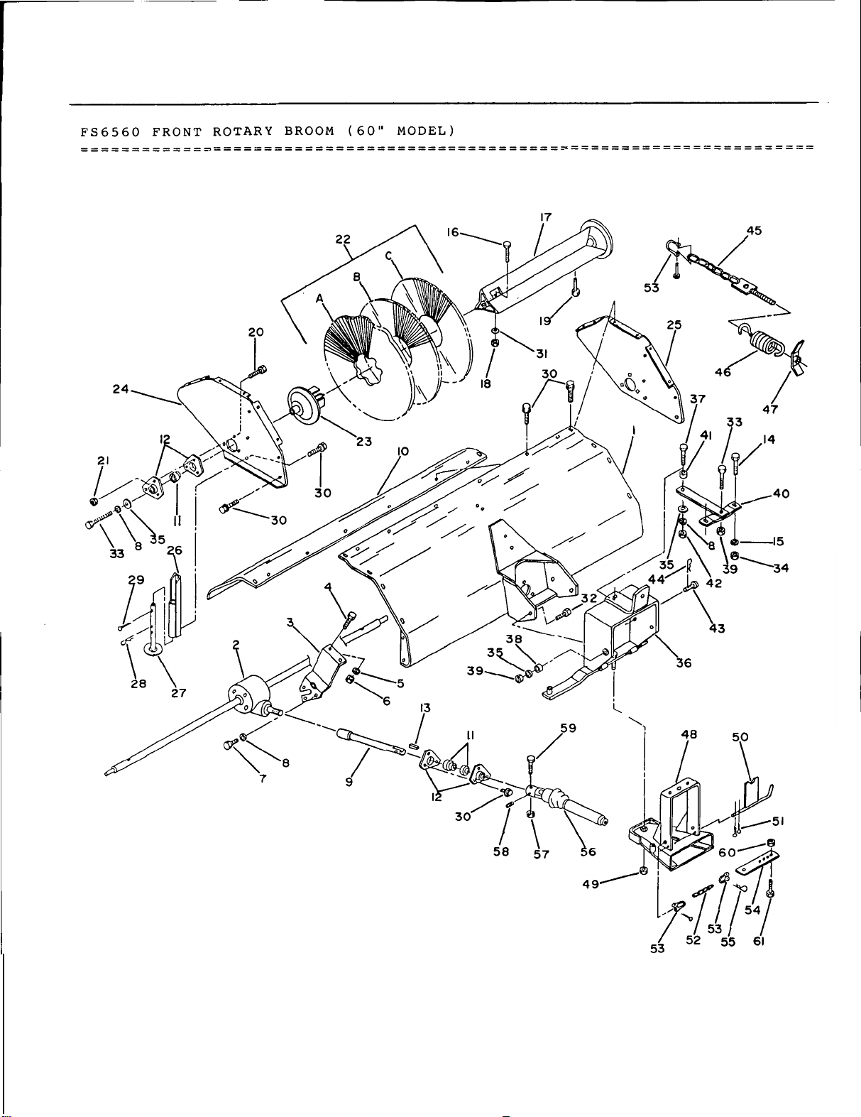
PARTS
GUIDE
OM
0179
60
Page 63
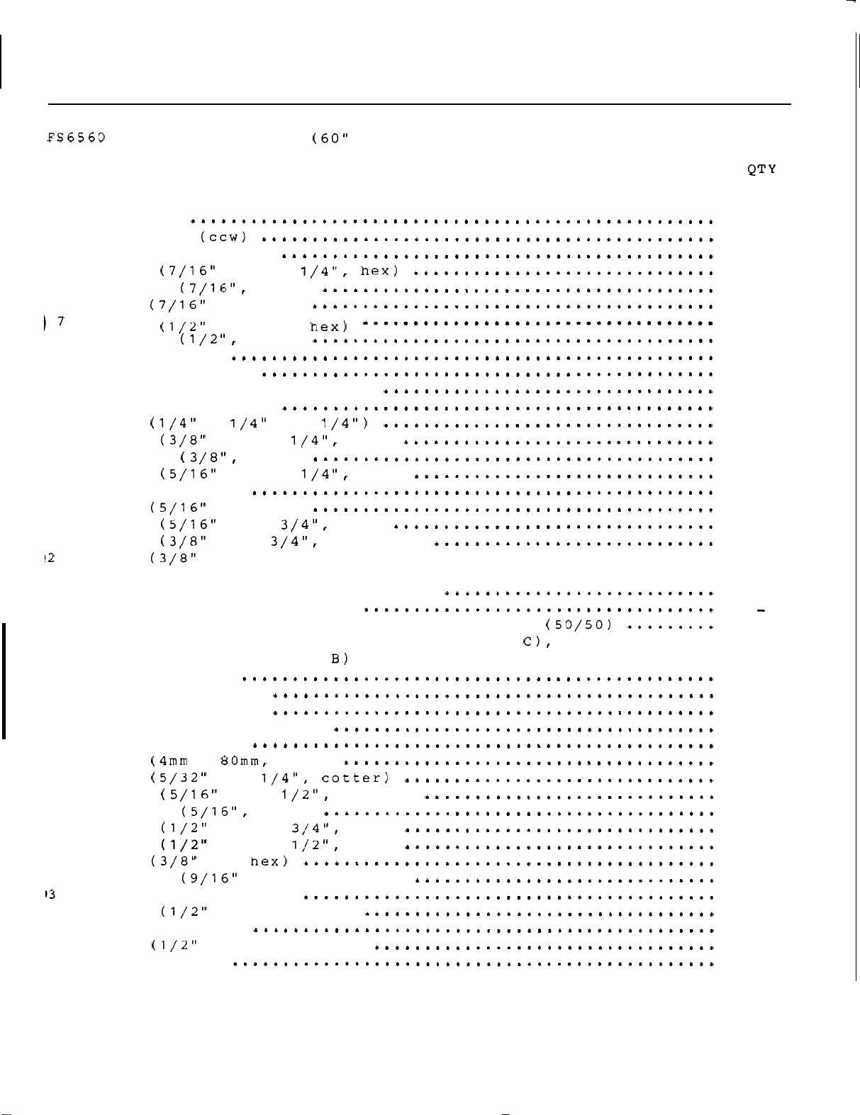
\
PARTS
I
........................................................................
........................................................................
REF DESCRIPTION
........................................................................
........................................................................
1
2
3
4
5 Washer
6
8
9 Input shaft
10
11
12 Bearing
13 Key (1/4"
14
15
16
17 Brush
18
19
20
1 Nut
22 Brush package
Housing
Gear
Gear
Bolt
Nut (7/16"
Bolt
box
box support
Washer
Hood
Bearing and locking
extension
retainer
Bolt
Washer
Bolt
support
Nut (5/16"
Bolt
Bolt
Includes:
brushes
23
24 Side
25 Side
26 Parking stand
27 Parking stand
28 Pin (4mm x 80mm. hair)
29 Pin
30
31
32
33
34
35
6
37
38 Pivot bushing
39
40 Support
Retainer
cup
plate
plate
Bolt
Washer
Bolt
Bolt
Nut
Washer
Adjustment bracket
Bolt
Nut
arm
NC x 1
NC.
NC
x
NC
NC
NC.
NC
NC
NC.
2
concave
5
deg
L.H.
R.H.
x
1
NC
NC
NC
NC.
NC
NC.
BROOM
hex)
x
1".
collar
x
1
x
1
lock)
x
2 1/4". hex)
hex)
X
hex)
hex)
x
flange)
:
Polypropylene
Steel
Polypropylene and
(item
support
x 1/2". flange)
X
1
x
1
dia
X
2".
nylon lock)
......................................
set
brushes
hole.
hex)
10
and
flat)
set
deg
26
steel
(item
zigzag
set
brushes
2 concave
(item
A)
GUIDE
1
1
1
2
2
2
6
1
1
3
6
1
2
2
2
2
2
2
6
6
1
.
.
2
1
1
2
2
2
2
33
2
2
3
2
5
1
1
2
3
1
OM
0179 61
Page 64
PARTS
GUIDE
........................................................................
........................................................................
REF DESCRIPTION QTY
........................................................................
........................................................................
41
42
43 Stopper pin
44 Pin
45 Ground
46 Tension
47 Adjustment handle
48 Female
49
50 Support bracket
51 Pin
52
53
54
55
56
57
58
59
60
61
Bushing
Nut
(3mm
x 65mm.
contact
spring
hitch
Nut
Stopper chain
Clevis
Chain
Pin (2.5mm
Driveline female half
support
Nut
Set
screw
Bolt
Nut
Bolt
NC.
BROOM
NC.
hex)
chain
NC.
uni-torque)
x
bracket
x
NC.
nylon lock)
NC
NC
X
nylon lock)
NC
x
(60
"
MODEL)
hair)
cotter)
x 1/2".
2 1/2.
1 1/2". hex)
allen)
hex)
1
1
1
1
1
1
1
1
1
2
2
OM
0179
62
Page 65
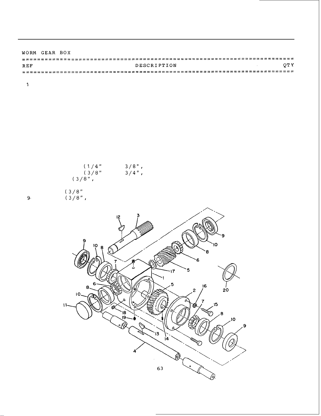
PARTS
GUIDE
2
3
4
5
6
7
8
9
10
11
12
13
14
15
16
17
18
1
20
Housing
Cover
Input shaft
Output Shaft
Worm and brass gear
Bearing cone
Bearing cone
Bearing cup
Seal
Internal retaining ring
Input
Key (woodruff)
Key (woodruff)
Set
Cap
Washer
External retainer ring
Plug (3/8" NPT)
Vent
Shim (use
....................................................
......................................................
................................................
...............................................
set
...............................................
...............................................
................................................
.......................................................
cap
..................................................
.............................................
.............................................
screw
screw
NF
x
NC
x 3/4". hex)
........................................
............................................
18
as
required)
NPT)
........................................
....................................
....................................
..........................
............................
.....................................
.....................................
1
1
1
1
1
2
2
4
3
4
1
1
1
1
4
4
1
2
1
.
OM
01
79
Page 66
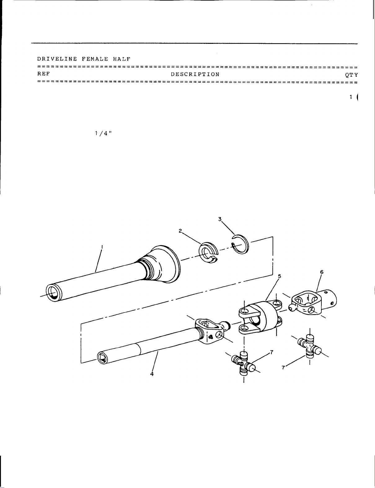
PARTS
GUIDE
1
2
3
4 Yoke and female shaft assembly
5
6
7
Inner shield
Nylon bearing
Bearing retainer
Double
Yoke
Universal joint kit
yoke (joint
1
...............................................
..............................................
...........................................
................................................
C.V.)
....................................
........................................
.............................
1
1
1
1
1
2
OM
0179
'
64
Page 67
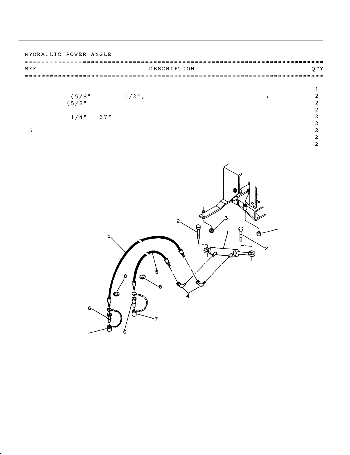
PARTS
GUIDE
1
2
3
4
5
6
8
Cylinder
Bolt
Nut
Elbow
Hose
Male
Yellow
Green
90 deg.
quick coupler
cap
plastic
...................................................
NC
x
NC,
uni-torque)
3
hex)
..
.
. . . .
. . . . . . . . .
..................................
..............................................
x 37"
............................................
.........................................
...................................................
plastic
ring (identification)
ring
.........................................
.......................
. . . . . . . . . . . . . .
3
OM
0179
7
65
Page 68
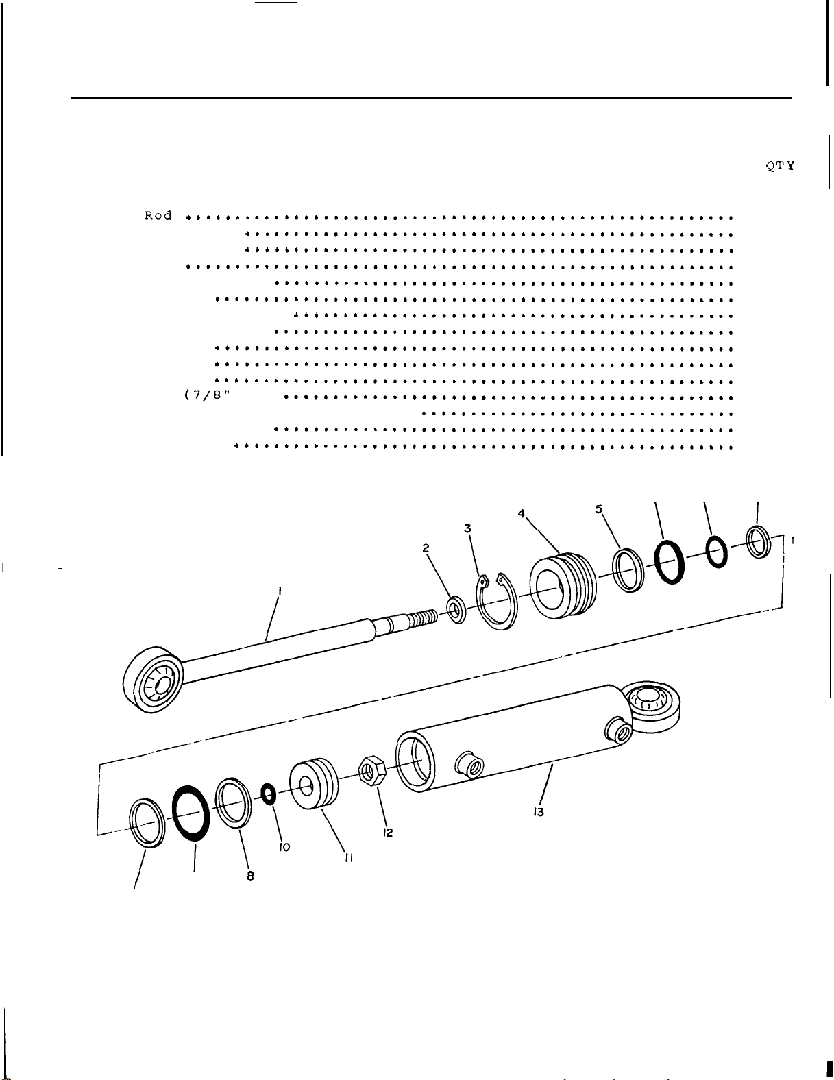
PARTS
GUIDE
HYDRAULIC CYLINDER
........................................................................
........................................................................
REF DESCRIPTION
.........................................................................
........................................................................
1
2
3
4
5
6
7
8
9
10
11
12
13
14
Rod
wiper
Snap ring
Cap
Back up
ring
0-Ring
0-Ring
Back
up
for
ring
0-Ring
0-Ring
Piston
Nut
Cylinder
Back up
ring
Seal kit
cap
NF)
tube
with
ball
end
1
1
1
1
1
1
1
2
1
1
1
1
1
1
OM
01
8
79
I
9
66
Page 69
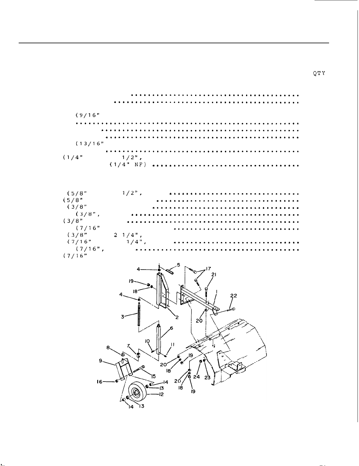
PARTS
GUIDE
FRONT
........................................................................
........................................................................
REF DESCRIPTION
........................................................................
........................................................................
1
2
3
4
5
6
7
8
9
10
11
12
13
14
15
16
17
18
19
20
21
22
23
24
WHEEL
Front wheel
Adjustable
Jack threaded rod
Washer
Handle
Jack housing
Wheel
Washer
Wheel
Pin
Grease
Wheel
Bearing
Shim
Bolt
bushing
bracket
fitting
and
.......................................................
Nut
Bolt
Washer
Nut
Washer
Bolt
Bolt
Washer
Nut
jack
dia
tire
with
NC
NC.
NC
NC.
NC
NC.
support
dia
dia
x
assembly
snap ring
X
nylon lock)
X
lock)
hex)
dia hole. flat)
x
NC
x
lock)
hex)
..........................................
hole.
hole.
1 1/2".
flat)
flat)
roll)
..............................
.............................
..............................
....................................
.....................................
5 1/2".
1".
1
hex)
hex)
hex)
hex)
...............................
........................................
1
1
1
2
1
1
1
1
1
1
1
1
2
2
1
1
5
7
7
6
2
1
1
1
OM
0179
67
Page 70
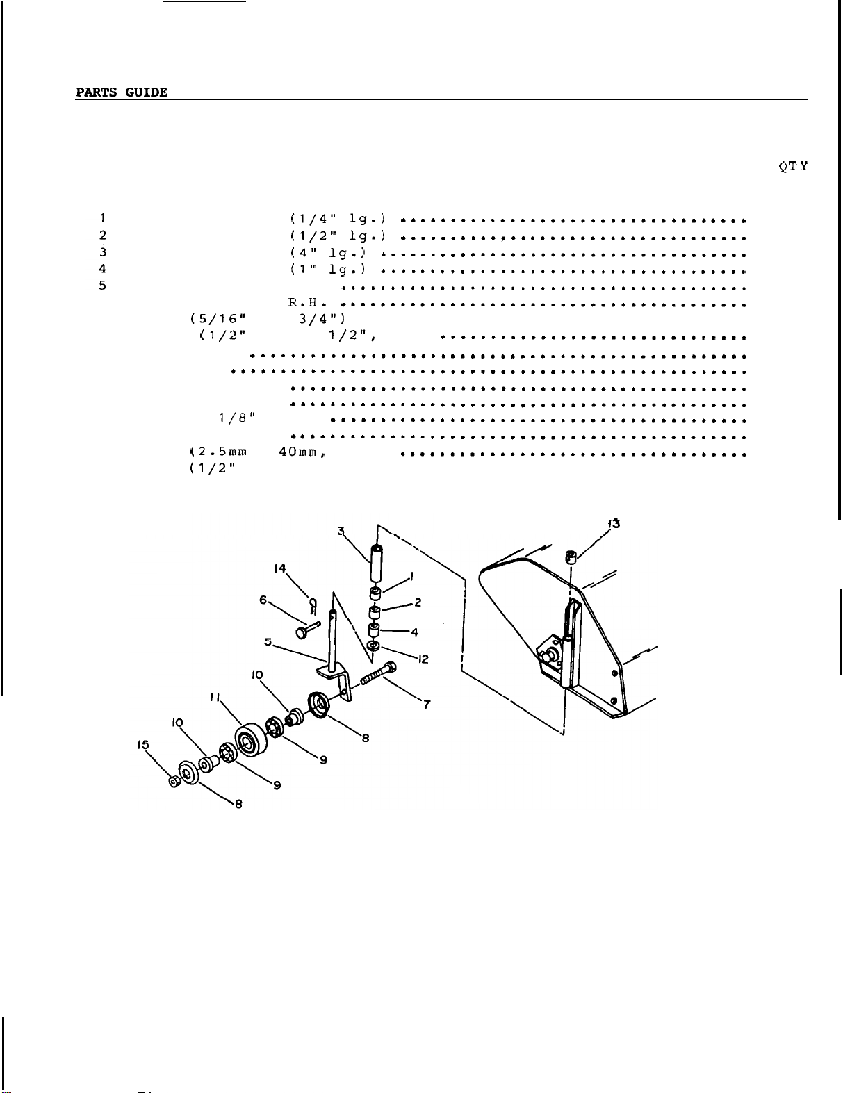
OPTIONAL CASTER
........................................................................
........................................................................
REF DESCRIPTION QT
........................................................................
........................................................................
WHEEL
(lawn
thatching and
etc.)
6
7
8
9
10
11
12
13
14
15
Spacer
Spacer sleeve
Spacer sleeve
Spacer sleeve
Wheel
Wheel
Pin
Bolt
Wheel
Bearing
Wheel
Plastic
Washer
Fixation tube
Pin
Nut
sleeve
bracket
bracket
x
NC
cup
bushing
wheel
thick
x
NC.
L.H.
1
x
3
nylon lock)
.......................................
hair)
hex)
..................................
2
2
2
10
1
1
1
2
4
4
4
2
2
2
2
2
OM
0179
68
Page 71
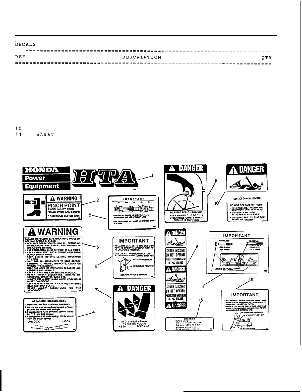
PARTS
GUIDE
1
2
3
4
5
6
7
8
9
12
13
HONDA HTA
Warning decal (blade, rotary broom)
Warning decal (snowblower, rotary broom)
Warning decal (quick hitch)
Important decal (rotary broom)
Important decal (rotary broom)
Danger decal auger (snowblower)
Danger decal chute (snowblower)
Danger decal hidden (driveline)
Danger decal (driveline)
decal (snowblower, blade, rotary broom)
.........................
................................
.............................
.............................
............................
............................
............................
...................................
.............................
Trip spring decal (blade)
Lubrication decal (snowblower)
..................................
.............................
..........
...................
ROTATING DRIVELINE
I
KEEP
AWAY!
3
4
2
1
1
1
2
1
3
3
1
1
1
I
OM
0179
HANDS.
69
J
r
I
I
Page 72
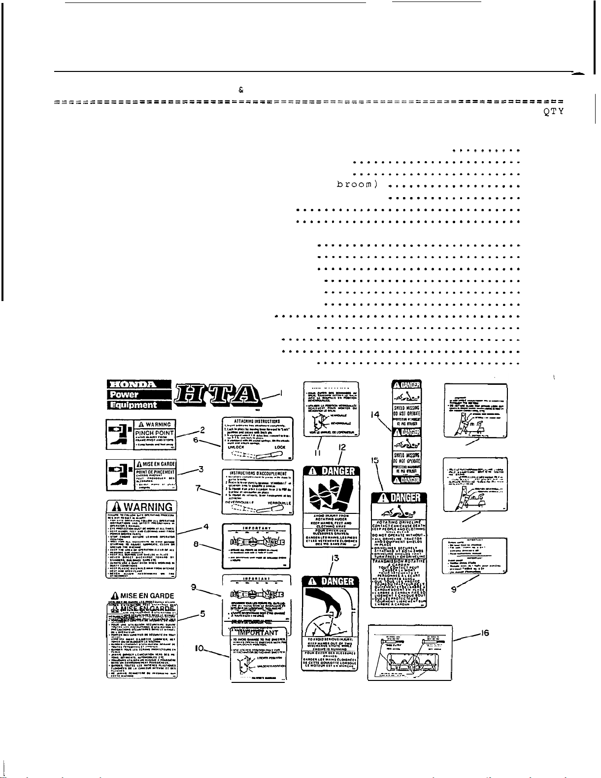
PARTS
GUIDE
DECALS (Bilingual English
REF
........................................................................
........................................................................
1
2
3
4
5
6
7
8
9
10
11
12
13
14
15
16
17
18
19
HONDA
Warning decal (blade. rotary broom)
Warning decal (blade. rotary broom)
Warning decal (snowblower. rotary broom)
Warning decal (snowblower. rotary broom)
Warning decal (quick hitch)
Warning decal (quick
Important decal (rotary broom)
Important decal (rotary broom)
Important decal (rotary broom)
Important decal (rotary broom)
Danger decal auger (snowblower)
Danger decal chute (snowblower)
Danger decal hidden (driveline)
Danger decal (driveline)
Shear bolts decal (snowblower)
Trip spring decal (blade)
Trip spring decal (blade)
Lubrication decal (snowblower)
HTA
decal (snowblower. blade. rotary broom)
French)
DESCRIPTION
hitch)
.............................
.
3
4
4
2
2
1
1
1
1
1
1
2
1
3
3
1
1
1
1
.
.
IMPORTANT
IMPORTANT
IMPORTANT
..
.....
I
7'
IMPORTANT
.
...
.
I8
..
.
I
..
.
I
.
...
OM
0179 70
.
Page 73
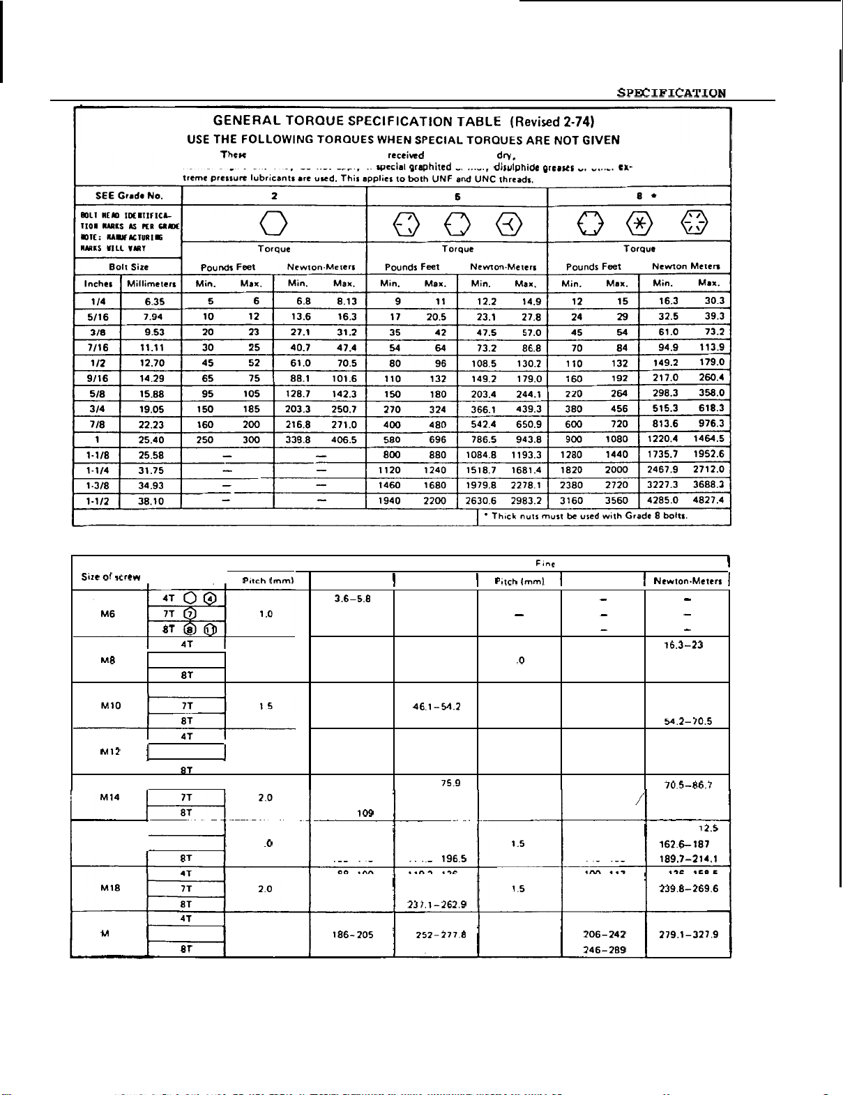
TORQUE
TABLE
I
Grade No.
I
M16 7T 2
OM
0179
t
20
NOTE: Thew values apply to fasteners as received from supplier,
normal engine oil. They do not apply if
77
41
41
71
41
41
77
METRIC
I
1
1.25
1.75
I
2.5
BOLT
TORQUE
Coarse
thread
Pounds
Feel
-
9.4
5.8
7.2
-
10
7.2
-
14
17-22
-
26
20
-
25
20
34-40
-
46
38
-
34
28
51
-
59
-
66
57
49
-
56
81
-
93 109.8- 126 1.5 90-106
96
-
67-77 90.8-104.3 69-83 93.5- 1 12.5
116-130 157.2-176.2
129- 145 174.8
88
-
100
150
-
168
175- 194
108
-
130 1463-176.2 132-150 178.9-203.3
213-249 288.6-337.4 333.3-391.6
Newton-Meters
130.1-147.7 107-124 145-168
119.2-136
203.3
or
moly dirulphidc greases or other
SPECIFICATIONS
I
4.9-7.9
7.9-12.7
9.8-13.6
9.8
-
19
23-29.8
27.1
-
35.2
27.1
-
33.9
51.5
-
62.3
37.9
-
46.1
69.1
-
79.9
77.2
-
89.4
66.4
-
-
-
227.6
71
or when lubricated with
thread
Pounds
-
1
22
-
1.25
1.5
35
-
-
52-64
120
-
-
-
100
-
177
202-231 273.7-313
Feel
17
25.7
-
36.6 19-27
-
42
31
47
52
29.8
27.1
47.4
42
75.9
84
-
-
-
-
-
39.3 20-29
63.7
55.6 31-41
92.1 56-68 1.25
101.6 62-75
,
122-143.6
138
158 189.7-214.1
-
158.5
117
199
136
Page 74
WARRANTY
SERVICE
Your satisfaction and goodwill
are
warranty details
any problems concerning
department. If you have
satisfaction,
Discuss your
can
be
with
the
we
suggest you take
problem
quickly resolved
Service Manager, contact
explained in
the
a
with
at
are
important
the
Distributor's Limited Warranty. Normally,
product
will
warranty problem
the
following action:
a
member
that
of dealership management. Often complaints
level. If
the
owner of
to
your dealer and to us.
be handled by your dealer's service
that
the
has
problem
the
not been handled to your
has
already been reviewed
dealership or
the
Manager.
If your problem
still
has
not been resolved to your satisfaction, contact
Power Equipment Customer Service Department of American Honda Motor Co.,Inc:
American Honda
Motor
Co.
,
Power Equipment Customer Service Department
100021
We
Georgia
Telephone:
will
need
0
Your name, address and telephone number
0
Product model and
0
Date
0
Dealer
0
Nature
the
following in order to
of purchase
name and address
of
the
problem
serial
301 36-9421
-
6400
number
assist
you:
All
General
Honda
the
After reviewing
taken. Please bear in mind
dealership,
important
that
Your purchase of
American Honda Motor Company.
your satisfaction
all
the
facts involved, you
using
dealer's
your initial contact
a
Honda product
with
your purchase.
that
facilities
We
For future reference, record your
spaces
below. Refer
to
this
information when ordering
or warranty inquiries.
Model:
Model:
Model:
Model:
Model:
Serial Number:
Serial
Serial
Serial
Serial Number: Date
Number:
Number:
Number:
your problem
be
with
is
greatly appreciated by both your dealer and
want to
unit's
assist
serial
will
,
equipment and personnel,
the
be advised of
will
likely
dealer.
be
you in every way possible to assure
number and date
parts
Date
Date
Date
Date
and when making technical
of
Purchase:
of
Purchase:
of
Purchase:
of
Purchase:
of
Purchase:
what
action can be
resolved
so
of
purchase in
it
at
is
the
very
the
Page 75

Page 76

H/C
3753936
Printed in Canada
 Loading...