

Page 1
dummyheaddummyhead
HOW TO USE THIS MANUAL
HOW TO USE THIS MANUAL
A Few Words About Safety
Service Information
The service and repair information contained in this manual is intended for use by qualified, professional te chnicians. Attempting
service or repairs without the proper training, tools, and equipment could cause injury to you or others. It could also damage the
vehicle or create an unsafe condition.
This manual describes the proper methods and procedures for performing service, maintenan ce and repairs. Some procedures
require the use of specially designed tool s and dedicated equipment. Any person who intends to use a replacement part, service
procedure or a tool that is not recommended by Honda, must determine the risks to their personal safe ty and the safe operation of
the vehicle.
If you need to replace a part, use genuine Honda parts with the correct part number or an equivalent part. We strongly recommend
that you do not use replacement parts of inferior quality.
For Your Customer’s Safety
Proper service and maintenance are essential to the customer’s safety and the reliability of the vehicle. Any error or oversight while
servicing a vehicle can result in faulty operation, damage to the vehicle, or injury to others.
Improper service or repairs can create an unsafe
condition that can cause your customer or others to
be seriously hurt or killed.
Follow the procedures and precautions in this
manual and other service materials carefully.
For Your Safety
Because this manual is intended for the professional service technician, we do no t provide warnings about many basic shop safety
practices (e.g., Hot parts–wear gloves). If you have not received shop safety training or do not feel confident about your knowledge
of safe servicing practice, we recommend that you do not attempt to perform the procedures described in this manual.
Some of the most important general service safety precautions are given below. However, we cannot warn you of every
conceivable hazard that can arise in performing service and repair procedu res. Only you can decide whether or not you should
perform a given task.
Failure to properly follow instructions and
precautions can cause you to be seriously hurt or
killed.
Follow the procedures and precautions in this
manual carefully.
Important Safety Precautions
Make sure you have a clear understanding of all basic shop safety p ractices and that you are wearing appropriate clothing and
using safety equipment. When performing any service task, be especially careful of the following:
• Read all of the instructions before you begin, and make sure you have the tools, the rep lacement or repair parts, and the skills
required to perform the tasks safely and completely.
• Protect your eyes by using proper safety glasses, goggl es or face shields any ti me you hammer, drill, gri nd, pry or wo rk arou nd
pressurized air or liquids, and springs or other stored-energy components. If there is any doubt, put on eye protection.
• Use other protective wear when necessary, for example gloves or safety shoes. Handling hot or sharp parts can cause severe
burns or cuts. Before you grab something that looks like it can hurt you, stop and put on gloves.
• Protect yourself and others whenever you have the vehicle up in the air. Any time you lift the vehicle, either with a hoist or a jack,
make sure that it is always securely supported. Use jack stands.
Make sure the engine is off before you begin any servicing procedu res, unless the instruction tells you to do otherwise. This will
help eliminate several potential hazards:
• Carbon monoxide poisoning from engine exhaust. Be sure there is adequate ventilation whenever you run the engine
• Burns from hot parts or coolant. Let the engine and exhaust system cool before working in those areas.
• Injury from moving parts. If the instruction tells you to run the engine, be sure your hands, fingers and clothing are out of the way.
Gasoline vapors and hydrogen gases from batteries are explosive. To reduce the po ssibility of a fire or ex plosion, be ca reful w hen
working around gasoline or batteries.
• Use only a nonflammable solvent, not gasoline, to clean parts.
• Never drain or store gasoline in an open container.
• Keep all cigarettes, sparks and flames away from the battery and all fuel-related parts.
0-1
Page 2
dummyheaddummyhead
HOW TO USE THIS MANUAL
How To Use This Manual
This manual describes the service procedures for the NC700X/XA/XD/S/SA/SD-C.
Sections 1, 2 and 3 apply to the whole motorcycle. Section 2 illustrates procedures for removal/installation of components that may
be required to perform service described in the following sections.
Section 4 through 23 describe parts of the motorcycle, grouped according to location.
If you are not familiar with this motorcycle, read Technical Feature in Section 1.
Follow the Maintenance Schedule recommendations to ensure that the motorcycle is in peak operating condition.
Performing the first scheduled maintenance is very important. It compensates for the initial wear that occurs during the break-in
period.
Find the section you want on this page, then turn to the table of contents on the first page of the section.
Most sections start with an assembly or system illustration, service information and troubleshooting for the section. The subsequent
pages give detailed procedure.
Refer to the troubleshooting in each section according to the malfunction or symptom. In case of an engine trouble, refer to PGM-FI
section troubleshooting first.
Your safety, and the safety of others, is very important. To help you make informed decisions we have provided safety
messages and other information throughout this manual. Of course, it is not practical or possible to warn you about all the
hazards associated with servicing this vehicle.
You must use your own good judgement.
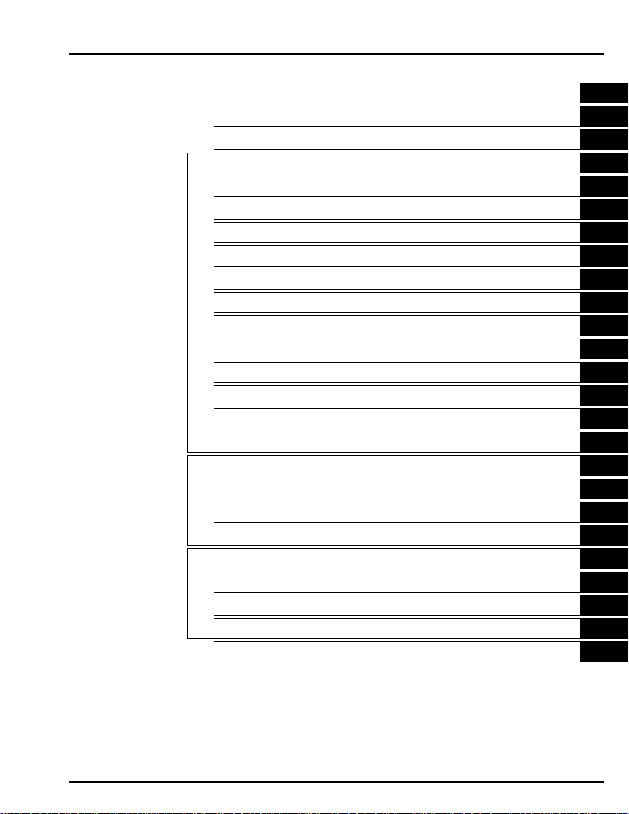
You will find important safety information in a variety of forms including:
• Safety Labels – on the vehicle
• Safety Messages – preceded by a safety alert symbol and one of three signal words, DANGER, WARNING, or CAUTION.
These signal words mean:
You WILL be KILLED or SERIOUSLY HURT if you don’t follow instructions.
You CAN be KILLED or SERIOUSLY HURT if you don’t follow instructions.
You CAN be HURT if you don’t follow instructions.
• Instructions – how to service this vehicle correctly and safely.
As you read this manual, you will find information that is preceded by a symbol. The purpose of this message is to help
prevent damage to your vehicle, other property, or the environment.
ALL INFORMATION, ILLUSTRATIONS, DIRECTIONS AND SPECIFICATIONS INCLUDED IN THIS PUBLICATION ARE
BASED ON THE LATEST PRODUCT INFORMATION AVAILABLE AT THE TIME OF APPROVAL FOR PRINTING. Honda
Motor Co., Ltd. RESERVES THE RIGHT TO MAKE CHANGES AT ANY TIME WITHOUT NOTICE AND WITHOUT
INCURRING ANY OBLIGATION WHATSOEVER. NO PART OF THIS PUBLICATION MAY BE REPRODUCED WITHOUT
WRITTEN PERMISSION. THIS MANUAL IS WRITTEN FOR PERSONS WHO HAVE ACQUIRED BASIC KNOWLEDGE OF
MAINTENANCE ON Honda MOTORCYCLES, MOTOR SCOOTERS OR ATVS.
© Honda Motor Co., Ltd.
SERVICE PUBLICATION OFFICE
Date of Issue: February 2012
0-2
Page 3

dummyheaddummyhead
HOW TO USE THIS MANUAL
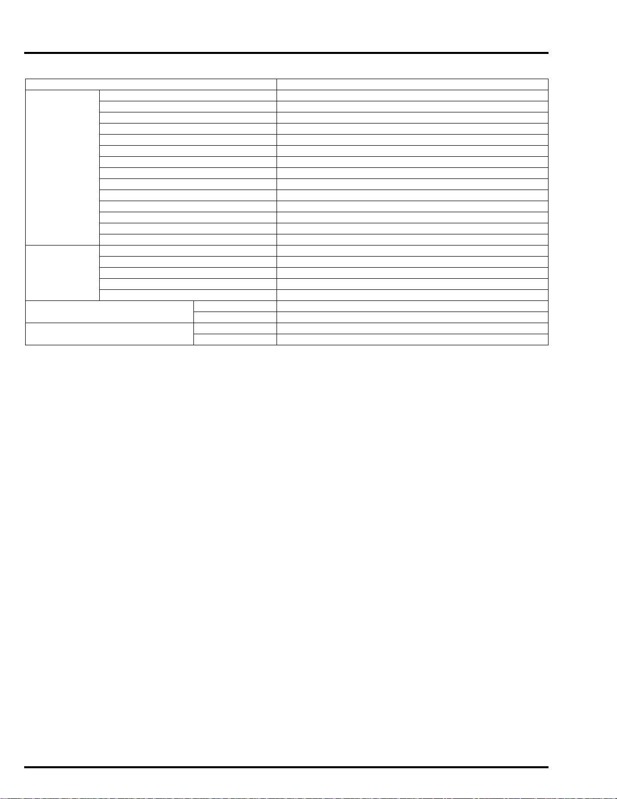
SYMBOLS
The symbols used throughout this manual show specific service procedures. If supplement ary info rmatio n is requi red p ertainin g to
these symbols, it would be explained specifically in the text without the use of the symbols.
Replace the part(s) with new one(s) before assembly.
Use the recommended engine oil, unless otherwise specified.
Use molybdenum oil solution (mixture of the engine oil and molybdenum grease in a ratio of 1:1).
Use multi-purpose grease (lithium based multi-purpose grease NLGI #2 or equivalent).
Use molybdenum disulfide grease (containing more than 3% molybdenum disulfide, NLGI #2 or
equivalent).
Example:
• Molykote® BR-2 plus manufactured by Dow Corning U.S.A.
• Multi-purpose M-2 manufactured by Mitsubishi Oil, Japan
Use molybdenum disulfide paste (containing more than 40% molybdenum disulfide, NLGI #2 or
equivalent).
Example:
• Molykote® G-n Paste manufactured by Dow Corning U.S.A.
• Honda Moly 60 (U.S.A. only)
• Rocol ASP manufactured by Rocol Limited, U.K.
• Rocol Paste manufactured by Sumico Lubricant, Japan
Use silicone grease.
Apply locking agent. Use a medium strength locking agent unless otherwise sp ecified.
Apply sealant.
Use DOT 4 brake fluid. Use the recommended brake fluid unless otherwise specified.
Use fork or suspension fluid.
0-3
Page 4
dummyheaddummyhead
CONTENTS
GENERAL INFORMATION
FRAME/BODY PANELS/EXHAUST SYSTEM
MAINTENANCE
PGM-FI SYSTEM
IGNITION SYSTEM
ELECTRIC STARTER
FUEL SYSTEM
COOLING SYSTEM
LUBRICATION SYSTEM
CYLINDER HEAD/VALVES
CLUTCH/GEARSHIFT LINKAGE (NC700X/XA/S/SA)
DUAL CLUTCH TRANSMISSION (DCT) (NC700XD/SD)
ALTERNATOR/STARTER CLUTCH
1
2
3
4
5
6
7
8
9
10
11
12
13
CRANKCASE/TRANSMISSION/BALANCER
ENGINE/DRIVE TRAIN ELECTRICAL
CRANKSHAFT/PISTON/CYLINDER
ENGINE REMOVAL/INSTALLATION
FRONT WHEEL/SUSPENSION/STEERING
REAR WHEEL/SUSPENSION
HYDRAULIC BRAKE
CHASSIS
ANTI-LOCK BRAKE SYSTEM (ABS)
BATTERY/CHARGING SYSTEM
LIGHTS/METERS/SWITCHES
FRAME
IMMOBILIZER SYSTEM (HISS)
ELECTRICAL
WIRING DIAGRAM
INDEX
14
15
16
17
18
19
20
21
22
23
24
Page 5

dummyheaddummyhead
MEMO
Page 6

dummytext
1. GENERAL INFORMATION
1
SERVICE RULES··········································1-2
MODEL IDENTIFICATION ····························1-3
SPECIFICATIONS·········································1-6
TORQUE VALUES······································1-15
LUBRICATION & SEAL POINTS ···············1-23
CABLE & HARNESS ROUTING·················1-25
EMISSION CONTROL SYSTEMS ··············1-86
TECHNICAL FEATURES····························1-87
1-1
Page 7
dummyheaddummyhead
GENERAL INFORMATION
GENERAL INFORMATION
SERVICE RULES
1. Use genuine Honda or Honda-recommende d parts and lubricants or their equivalents. Parts that don't meet Honda's desi gn
specifications may cause damage to the motorcycle.
2. Use the special tools designed for this product to avoid damage and incorrect assembly.
3. Use only metric tools when servicing the motorcycle. Metric bolts, nuts and screws are not interchangeable with English
fasteners.
4. Install new gaskets, O-rings, cotter pins, and lock plates when reassembling.
5. When tightening bolts or nuts, begin with the larger diameter or inner bolt first. Then tighten to the specified torque diagonally in
incremental steps unless a particular sequence is specified.
6. Clean parts in cleaning solvent upon disassembly. Lubricate any slid ing surfaces before reassembly.
7. After reassembly, check all parts for proper installation and operation.
8. Route all electrical wires as show in the Cable and Harness Routing (page 1-25).
9. Do not bend or twist control cables. Damaged control cables will no t operate smoothly and may stick or bind.
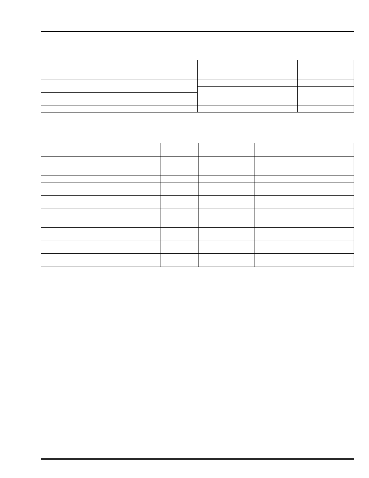
ABBREVIATION
Throughout this manual, the following abbreviations are used to iden tify the respective parts or systems.
Abbrev. term Full term
ABS (NC700XA/XD/SA/SD) Anti-lock Brake System
CKP sensor Crankshaft Position sensor
DCT (NC700XD/SD) Dual Clutch Transmission
DLC Data Link Connector
DTC Diagnostic Trouble Code
ECM (NC700X/XA/S/SA) Engine Control Module
ECT sensor Engine Coolant Temperature sensor
EEPROM Electrically Erasable Programmable Read Only Memory
EOP sensor (NC700XD/SD) Engine Oil Pressure sensor
EOP switch Engine Oil Pressure switch
EOT sensor (NC700XD/SD) Engine Oil Temperature sensor
HDS Honda Diagnostic System
HISS Honda Ignition Security System
IACV Idle Air Control Valve
IAT sensor Intake Air Temperature sensor
MAP sensor Manifold Absolute Pressure sensor
MIL Malfunction Indicator Lamp
2 sensor Oxygen sensor
O
PCM (NC700XD/SD) Power Control Module
PCV Proportional Co ntrol Valve
PGM-FI Programmed Fuel Injection
SCS connector Service Check Short connector
TP sensor Throttle Position sensor
TR sensor (NC700XD/SD) Transmission Range Sensor
VS sensor Vehicle Speed sensor
DESTINATION CODE
Throughout this manual, the following codes are used to identify individual types for each region.
DESTINATION CODE REGION
EU.K.
III E U.K. type III
ED EUROPEAN DIRECT SALES
II ED EUROPEAN DIRECT SALES type II
FFrance
II F France type II
KO Korea
RU Russia
U Australia, New Zealand
1-2
Page 8

dummyheaddummyhead
MODEL IDENTIFICATION
NC700XA shown:
GENERAL INFORMATION
NC700SA shown:
This manual covers following types of NC700 models:
TYPE
Standard brake – – – –
ABS – –
DCT –– ––
NC700X NC700XA NC700XD NC700S NC700SA NC700SD
NC700X NC700S
Be sure to refer to the procedure for the appropriate version of the NC700.
1-3
Page 9
dummyheaddummyhead
[1]
[1]
[1]
[1]
GENERAL INFORMATION
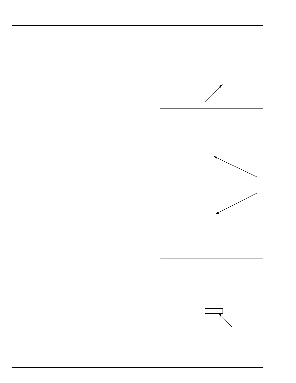
SERIAL NUMBERS
The Vehicle Identification Number (V.I.N) [1] is stamped on the right side of
the steering head.
The registered number plate (E, F, ED, RU types) [1] and compliance plate
(U type only) is attached on the left side of the steering head.
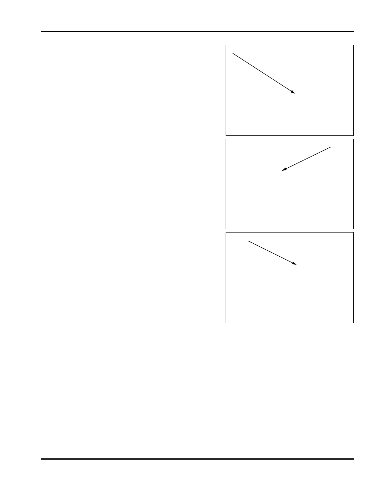
The engine serial number [1] is stamped on the lower right side of the
crankcase.
The throttle body identification number [1] is stamped on the lower left side
of the throttle body as shown.
1-4
Page 10
dummyheaddummyhead
[1]
[1]
[1]
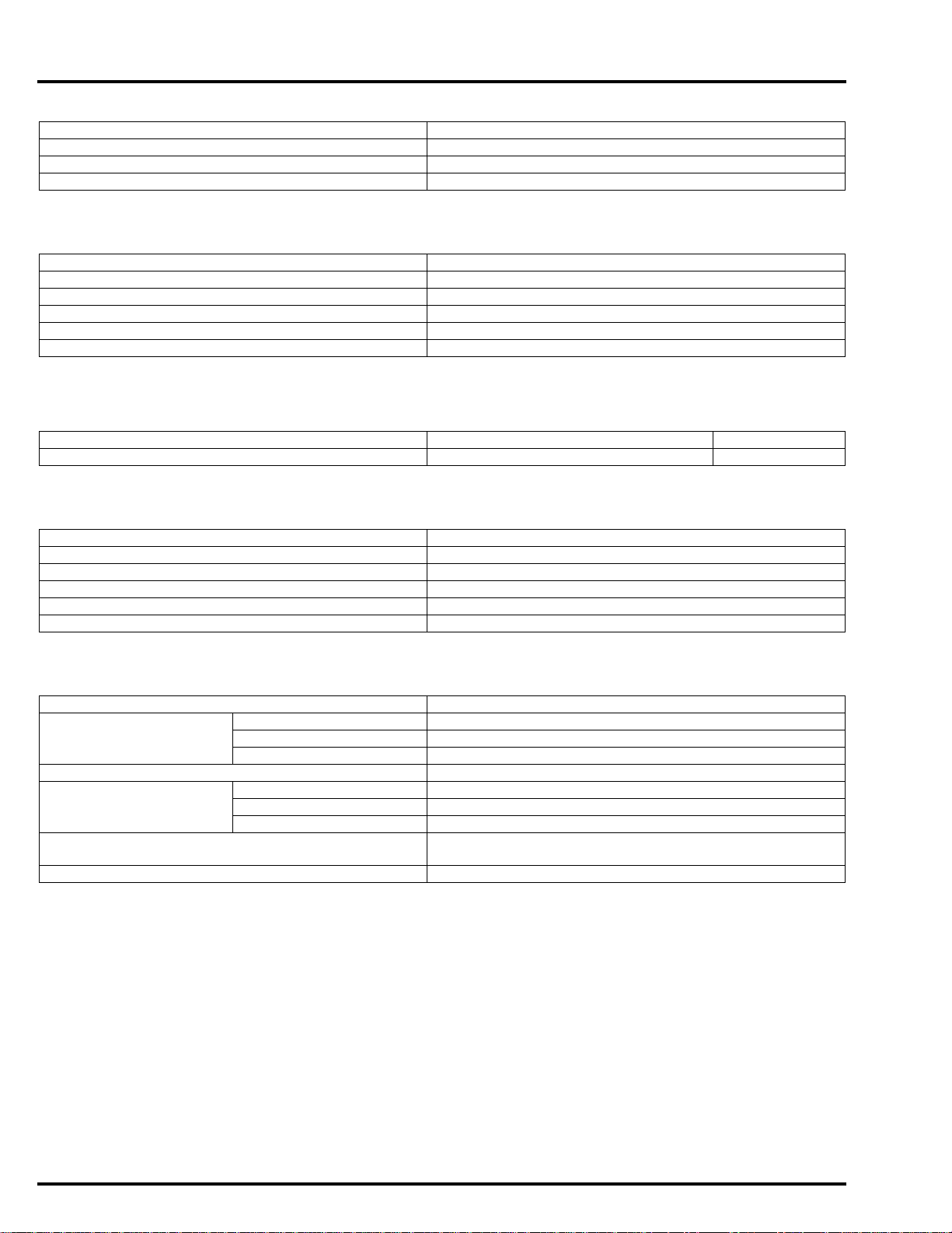
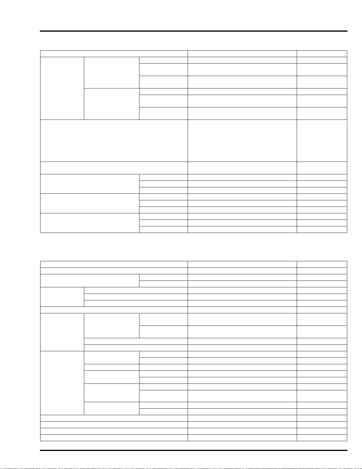
LABELS
The color label [1] is attached on the right side of the rear frame. When
ordering color-coded parts, always specify the designated color code.
The Safety Certification Label (KO type) [1] is located on the left side of the
rear frame.
GENERAL INFORMATION
The Emission Control Information Label (KO type) [2] is located on the left
side of the rear frame.
1-5
Page 11

dummyheaddummyhead
GENERAL INFORMATION
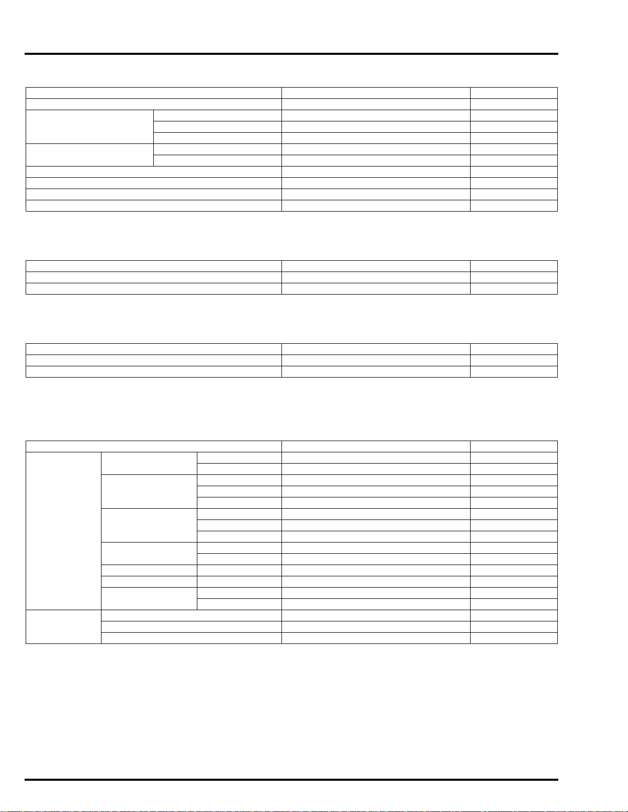
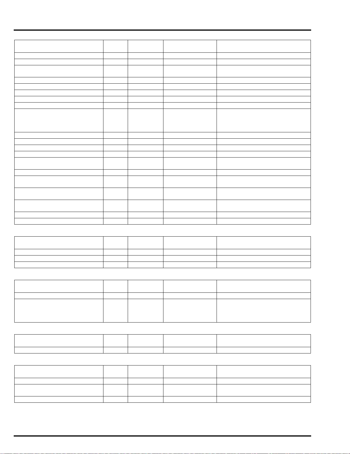
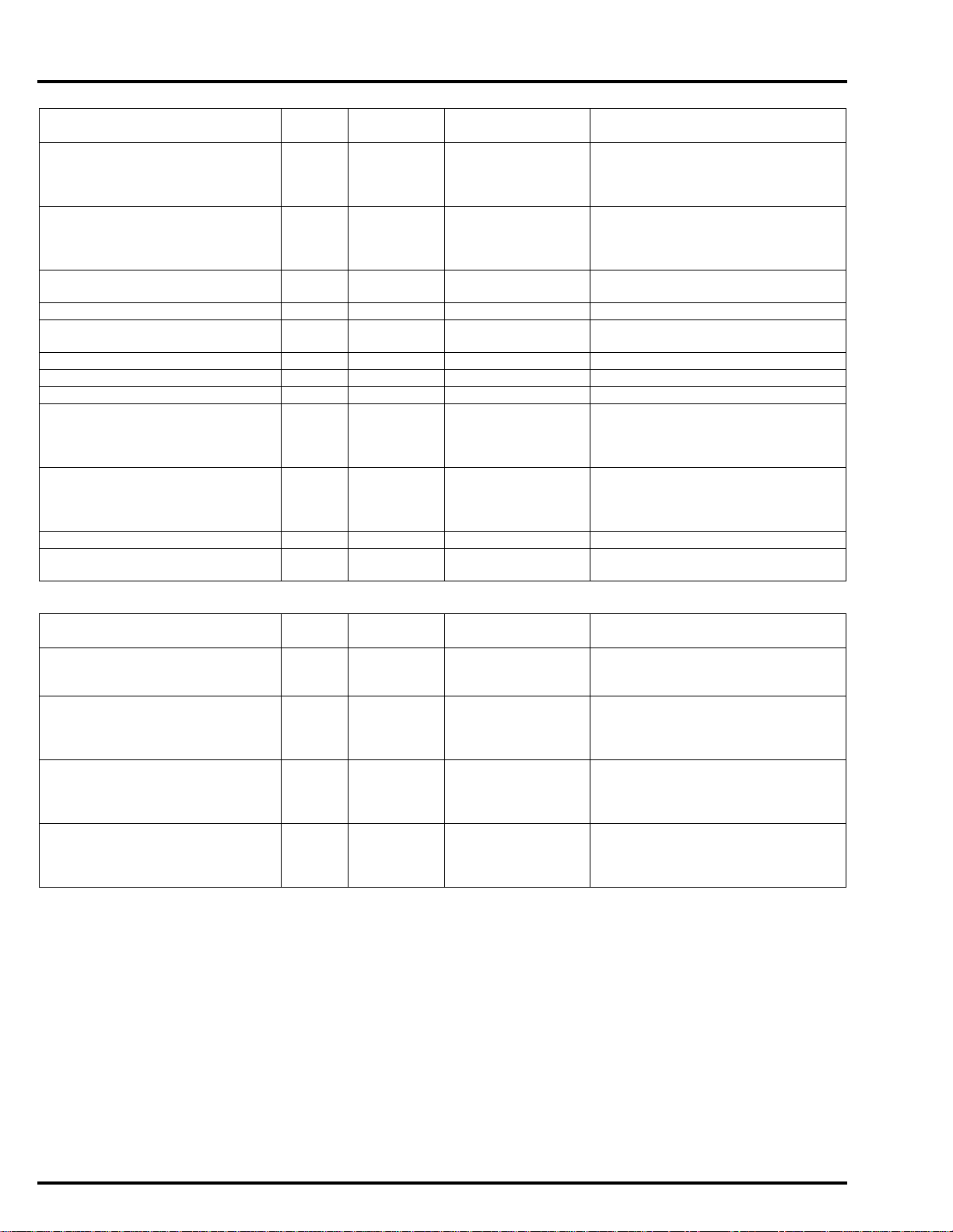
SPECIFICATIONS
GENERAL SPECIFICATIONS
ITEM SPECIFICATIONS
DIMENSIONS Overall length NC700X/XA/XD 2,210 mm (87.0 in)
NC700S/SA/SD 2,195 mm (86.4 in)
Overall width E, ED, F,
RU, U type
KO type NC700XA 825 mm (32.5 in)
Overall height NC700X/XA/XD 1,285 mm (50.6 in)
Wheelbase NC700X/XA/XD 1,540 mm (60.6 in)
Seat height NC700X/XA/XD 830 mm (32.7 in)
Footpeg height NC700X/XA/XD 341 mm (13.4 in)
Ground clearance NC700X/XA/XD 165 mm (6.5 in)
Curb weight E, ED, F,
RU, U type
KO type NC700XA 220 kg (485 lbs)
Maximum weight capacity E, ED, F, RU, U type 209 kg (461 lbs)
FRAME Frame type Diamond
Front suspension Telescopic fork
Front axle travel NC700X/XA/XD 137 mm (5.4 in)
Rear suspension Swingarm
Rear axle travel NC700X/XA/XD 150 mm (5.9 in)
Front tire size 120/70ZR17M/C (58W)
Rear tire size 160/60ZR17M/C (69W)
Front tire brand BRIDGESTONE BT023F G
Rear tire brand BRIDGESTONE BT023R G
Front brake Hydraulic single disc
Rear brake Hydraulic single disc
Caster angle 27°
Trail length 110 mm (4.3 in)
Fuel tank capacity 14.1 liters (3.73 US gal, 3.1 Imp gal)
NC700X/XA/XD 830 mm (32.7 in)
NC700S/SA/SD 760 mm (29.9 in)
NC700S/SA/SD 1,130 mm (44.5 in)
NC700S/SA/SD 1,525 mm (60.0 in)
NC700S/SA/SD 790 mm (31.1 in)
NC700S/SA/SD 310 mm (12.2 in)
NC700S/SA/SD 140 mm (5.5 in)
NC700X 214 kg (472 lbs)
NC700XA 218 kg (481 lbs)
NC700XD 228 kg (503 lbs)
NC700S 211 kg (465 lbs)
NC700SA 215 kg (474 lbs)
NC700SD 225 kg (496 lbs)
KO type 189 kg (417 lbs)
NC700S/SA/SD 107 mm (4.2 in)
NC700S/SA/SD 120 mm (4.7 in)
METZELER ROADTEC Z8 INTERACT E
METZELER ROADTEC Z8 INTERACT
1-6
Page 12

dummyheaddummyhead
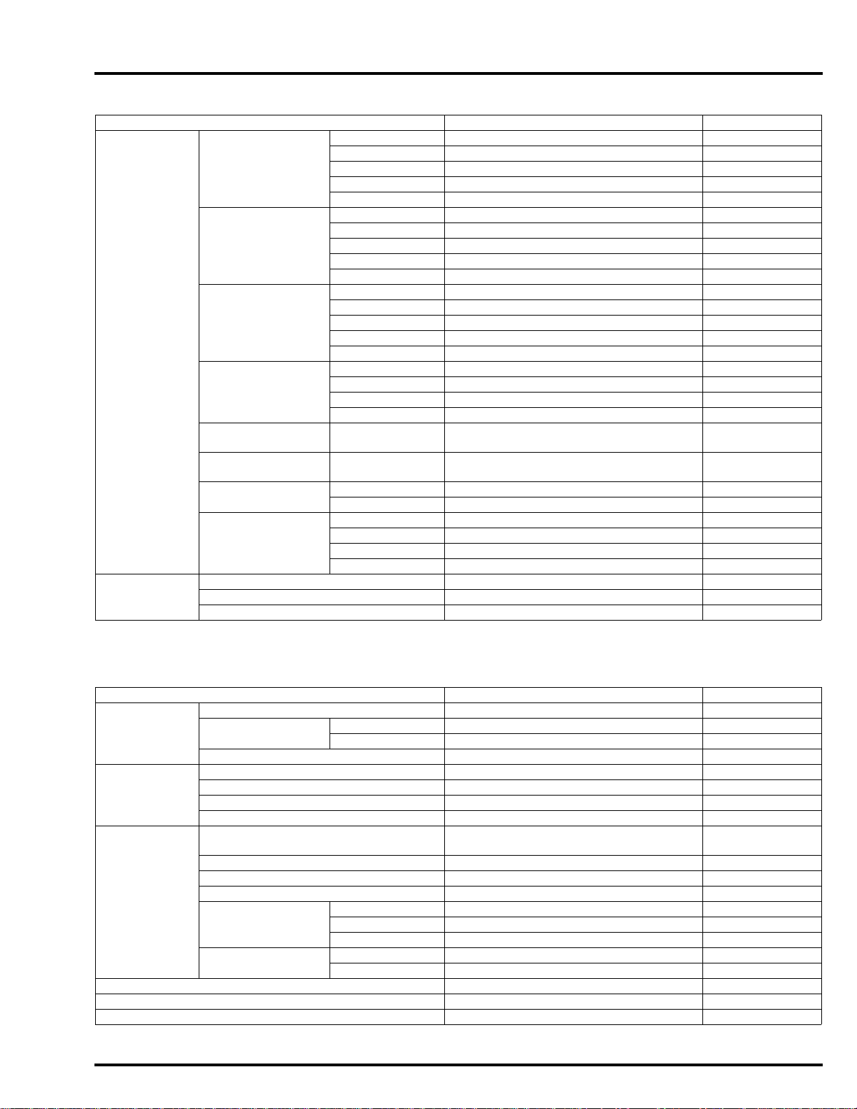
GENERAL INFORMATION
ITEM SPECIFICATIONS
ENGINE Cylinder arrangement 2 cylinders in-line, slant angle 55°
Bore and stroke 73.0 x 80.0 mm (2.87 x 3.15 in)
Displacement 670 cm3 (40.9 cu-in)
Compression ratio 10.7:1
Valve train Chain driven, OHC with rocker arm
Intake valve opens at 1 mm (0.04 in) lift No.1: – 20° BTDC
No.2: – 25° BTDC
closes at 1 mm (0.04 in) lift 27° ABDC
Exhaust valve opens at 1 mm (0.04 in) lift 30° BBDC
closes at 1 mm (0.04 in) lift No.1: – 15° ATDC
No.2: – 20° ATDC
Lubrication system Forced pressure and wet sump
Oil pump type Trochoid
Cooling system Liquid cooled
Air filtration Paper element
Engine dry weight NC700X/XA/S/SA 60.5 kg (133.4 lbs)
NC700XD/SD 67.3 kg (148.4 lbs)
Firing order 1 - 2
FUEL DELIVERY
SYSTEM
DRIVE TRAIN Clutch system NC700X/XA/S/SA Multi-plate, wet
ELECTRICAL Ignition system Computer-controlled digital
Type PGM-FI (Programmed Fuel Injection)
Throttle bore 36 mm (1.4 in)
NC700XD/SD 2 Multi-plate wet clutches
Clutch operation system NC700X/XA/S/SA Cable operating
NC700XD/SD Automatic
Transmission Constant mesh, 6-speeds
Primary reduction NC700X/XA/S/SA 1.731 (71/41)
NC700XD/SD 1.921 (73/38)
Final reduction NC700X/XA/S/SA 2.687 (43/16)
NC700XD/SD 2.437 (39/16)
Gear ratio NC700X/XA/S/SA 1st 2.812 (45/16)
2nd 1.894 (36/19)
3rd 1.454 (32/22)
4th 1.200 (30/25)
5th 1.033 (31/30)
6th 0.837 (31/37)
NC700XD/SD 1st 2.666 (40/15)
2nd 1.904 (40/21)
3rd 1.454 (32/22)
4th 1.200 (30/25)
5th 1.033 (31/30)
6th 0.837 (31/37)
Gearshift pattern NC700X/XA/S/SA Left foot operated return system,
1 - N - 2 - 3 - 4 - 5 - 6
NC700XD/SD Automatic and electric shift (left hand
operated) return system,
N - 1 - 2 - 3 - 4 - 5 - 6
transistorized with electric advance
Starting system Electr ic starter motor
Charging system Triple phase output alternator
Regulator/rectifier FET shorted/triple phase full wave
rectification
Lighting system Battery
1-7
Page 13
dummyheaddummyhead
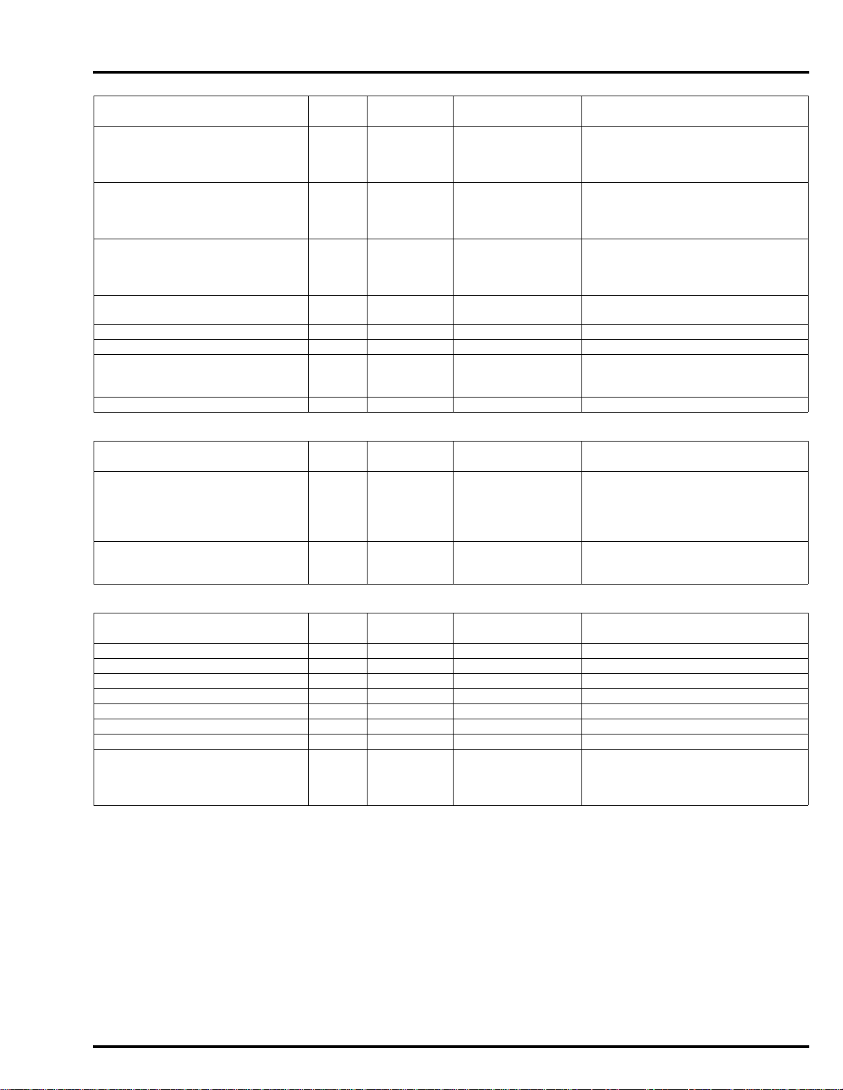
GENERAL INFORMATION
PGM-FI SPECIFICATIONS
ITEM SPECIFICATIONS
IAT sensor resistance (at 20°C/68°F) 2.2 – 2.7 k
ECT sensor resistance (at 40°C/104°F) 1.0 – 1.3 k
Injector resistance (at 20°C/68°F) 11 – 13
IGNITION SYSTEM SPECIFICATIONS
ITEM SPECIFICATIONS
Spark plug (Iridium) IFR6G-11K (NGK)
Spark plug gap 1.0 – 1.1 mm (0.039 – 0.043 in)
Ignition coil peak voltage 100 V minimum
CKP sensor peak voltage (at 20°C/68°F) 0.7 V minimum
Ignition timing ("F" mark) 12° BTDC at idle
ELECTRIC STARTER SPECIFICATION
ITEM STANDARD SERVICE LIMIT
Starter motor brush length 12.0 – 13.0 (0.47 – 0.51) 6.5 (0.26)
Unit: mm (in)
FUEL SYSTEM SPECIFICATIONS
ITEM SPECIFICATIONS
Throttle body identification number GQ3UA
Idle speed 1,200 ± 100 min
Throttle grip freeplay 2 – 6 mm (1/16 – 1/4 in)
Fuel pressure at idle 343 kPa (3.5 kgf/cm
Fuel pump flow (at 12 V) 230 cm3 (7.8 US oz, 8.1 Imp oz) minimum/10 seconds
-1
(rpm)
2
, 50 psi)
COOLING SYSTEM SPECIFICATIONS
ITEM SPECIFICATIONS
Coolant capacity Radiator and engine 1.69 liters (1.79 US qt, 1.49 Imp qt)
At draining 1.41 liters (1.49 US qt, 1.24 Imp qt)
Reserve tank 0.13 liter (0.14 US qt, 0.11 Imp qt)
Radiator cap relief pressure 108 – 137 kPa (1.1 – 1.4 kgf/cm
Thermostat Begin to open 80 – 84°C (176 – 183°F)
Fully open 95°C (203°F)
Valve lift 8 mm (0.3 in) minimum
Recommended antifreeze High quality ethylene glycol antifreeze containing silicate-free
corrosion inhibitors
Standard coolant concentration 1:1 (mixture with distilled water)
2
, 16 – 20 psi)
1-8
Page 14
dummyheaddummyhead
GENERAL INFORMATION
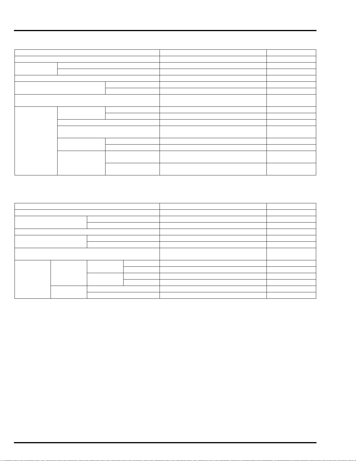
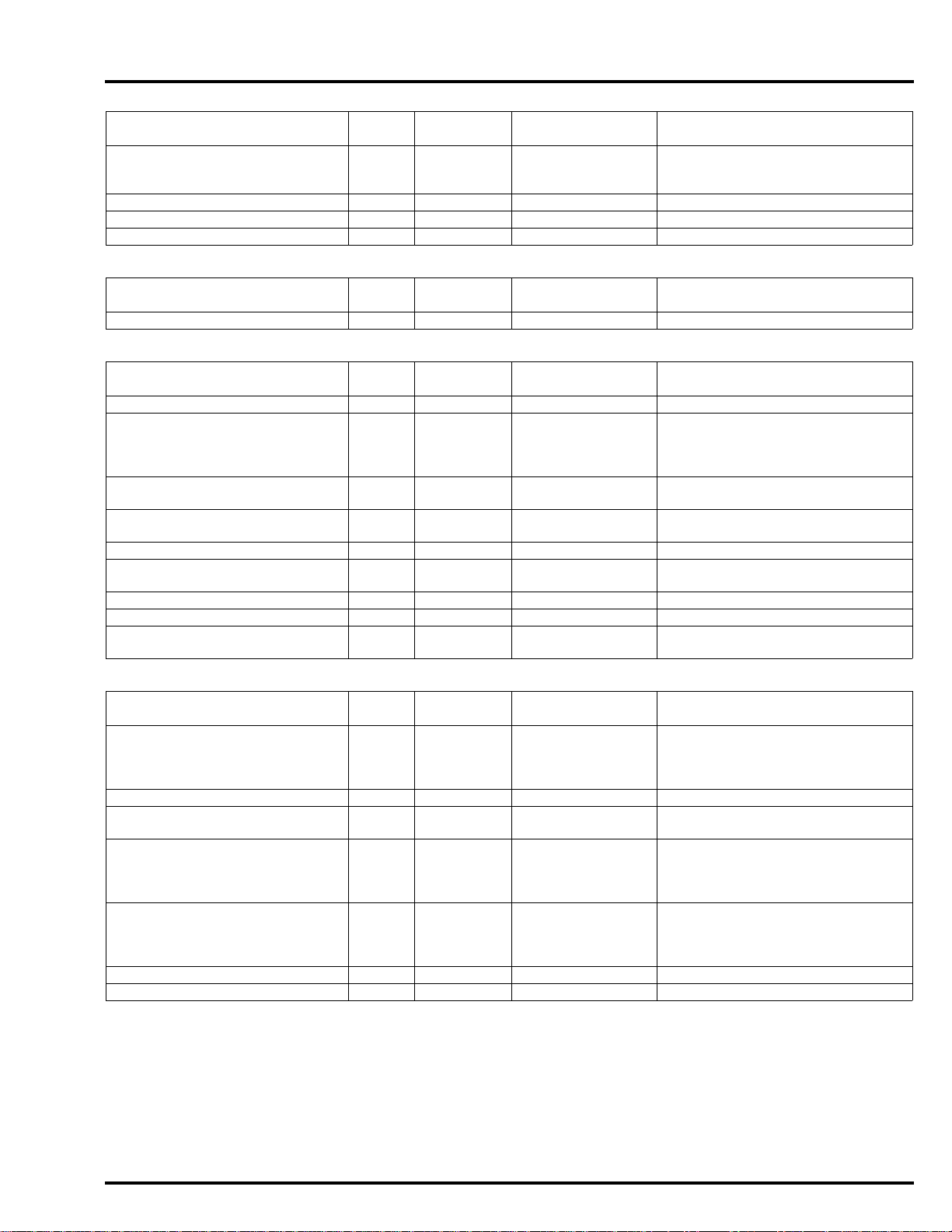
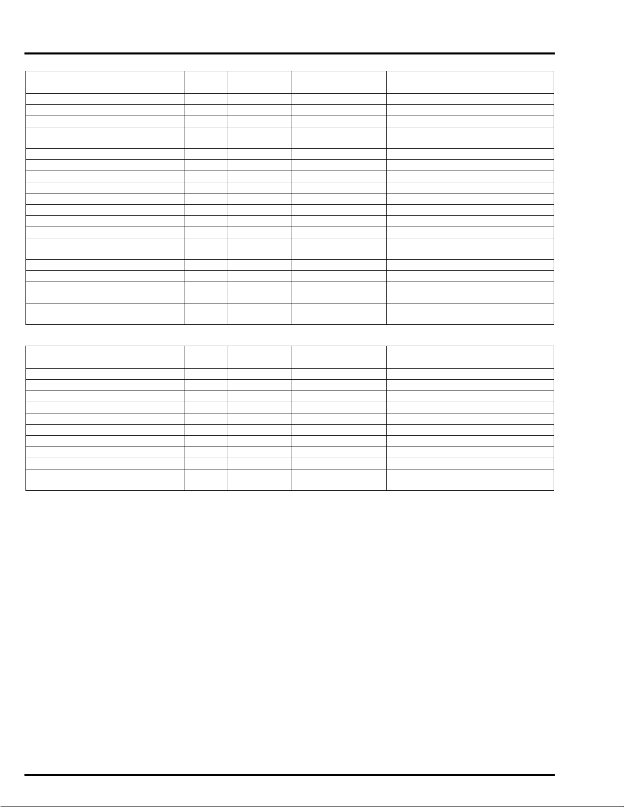
LUBRICATION SYSTEM SPECIFICATIONS
ITEM ST ANDARD SERVICE LIMIT
Engine oil
capacity
Recommended engine oil Honda "4-stroke motorcycle oil" or an
Oil pressure at engine oil filter 470 kPa (4.8 kgf/cm
Oil pump rotor (NC700X/XA/S/SA) Tip clearance 0.15 (0.006) 0.20 (0.008)
Engine oil pump rotor (NC700XD/SD) Tip clearance 0.15 (0.006) 0.20 (0.008)
Clutch oil pump rotor (NC700XD/SD) Tip clearance 0.15 (0.006) –
NC700X/XA/S/SA After draining 3.1 liters (3.3 US qt, 2.7 Imp qt) –
After draining/
filter change
After
disassembly
NC700XD/SD After draining 3.2 liters (3.4 US qt, 2.8 Imp qt) –
After draining/
filter change
After
disassembly
Body clearance 0.15 – 0.21 (0.006 – 0.008) 0.35 (0.014)
Side clearance 0.04 – 0.09 (0.002 – 0.004) 0.12 (0.005)
Body clearance 0.15 – 0.21 (0.006 – 0.008) 0.35 (0.014)
Side clearance 0.04 – 0.09 (0.002 – 0.004) 0.12 (0.005)
Body clearance 0.15 – 0.21 (0.006 – 0.008) –
Side clearance 0.04 – 0.09 (0.002 – 0.004) –
3.4 liters (3.6 US qt, 3.0 Imp qt) –
3.7 liters (3.9 US qt, 3.3 Imp qt) –
3.4 liters (3.6 US qt, 3.0 Imp qt) –
4.1 liters (4.3 US qt, 3.6 Imp qt) –
equivalent
API service classification: SG or higher
(except oils labeled as energy conserving
on the circular API service label)
Viscosity: SAE 10W-30
JASO T 903 standard: MA
at 5,000 min
-1
2
, 68 psi)
(rpm)/(80°C/176°F)
Unit: mm (in)
–
–
CYLINDER HEAD/VALVES SPECIFICATIONS
Unit: mm (in)
ITEM ST ANDARD SERVICE LIMIT
Cylinder compression at 470 min-1(rpm) 1,775 kPa (18.1 kgf/cm2, 257 psi) –
Valve clearance IN 0.17 ± 0.02 (0.007 ± 0.001) –
EX 0.28 ± 0.02 (0.011 ± 0.001) –
Rocker arm,
rocker arm
shaft
Cam chain tensioner wedge B length – 6.0 (0.24)
Camshaft Cam lobe height
Valve, valve
guide
Valve spring free length 49.07 (1.932) 48.1 (1.89)
Cylinder head warpage – 0.10 (0.004)
Cylinder head camshaft journal I.D. 41.995 – 42.019 (1.6533 – 1.6543) 42.027 (1.6546)
Cylinder head-to-camshaft clearance 0.045 – 0.084 (0.0018 – 0.0033) 0.10 (0.004)
Rocker arm I.D. 20.012 – 20.030 (0.7879 – 0.7886) 20.041 (0.7890)
Rocker arm shaft O.D. 1 9.972 – 19.993 (0.7863 – 0.7871) 19.961 (0.7859)
Rocker arm-to-shaft clearance 0.019 – 0.058 (0.0007 – 0.0023) 0.08 (0.003)
IN 34.7897 – 35.0297 (1.36967 – 1.37912)
EX 34.9227 – 35.1627 (1.37491 – 1.38436)
Runout – 0.04 (0.002)
Camshaft journal O.D. 41.935 – 41.950 (1.6510 – 1.6516) 41.927 (1.6507)
Valve stem O.D. IN 4.975 – 4.990 (0.1959 – 0.1965) 4.965 (0.1955)
EX 4 .965 – 4.980 (0.1955 – 0.1961) 4.955 (0.1951)
Valve guide I.D. IN/EX 5.000 – 5.012 (0.1969 – 0.1973) 5.04 (0.198)
Stem-to-guide
clearance
Valve guide
projection above
cylinder head
Valve seat width IN 0.90 – 1.10 (0.035 – 0.043) 1.5 (0.06)
IN 0.010 – 0.037 (0.0004 – 0.0015) 0.075 (0.0030)
EX 0 .020 – 0.047 (0.0008 – 0.0019) 0.085 (0.0033)
IN 17.7 – 18.0 (0. 70 – 0.71) –
EX 19.6 – 19.9 (0.77 – 0.78) –
EX 1.30 – 1.50 (0.051 – 0.059) 1.9 (0.07)
34.7697
(1.36888)
34.9027
(1.37412)
1-9
Page 15
dummyheaddummyhead
GENERAL INFORMATION
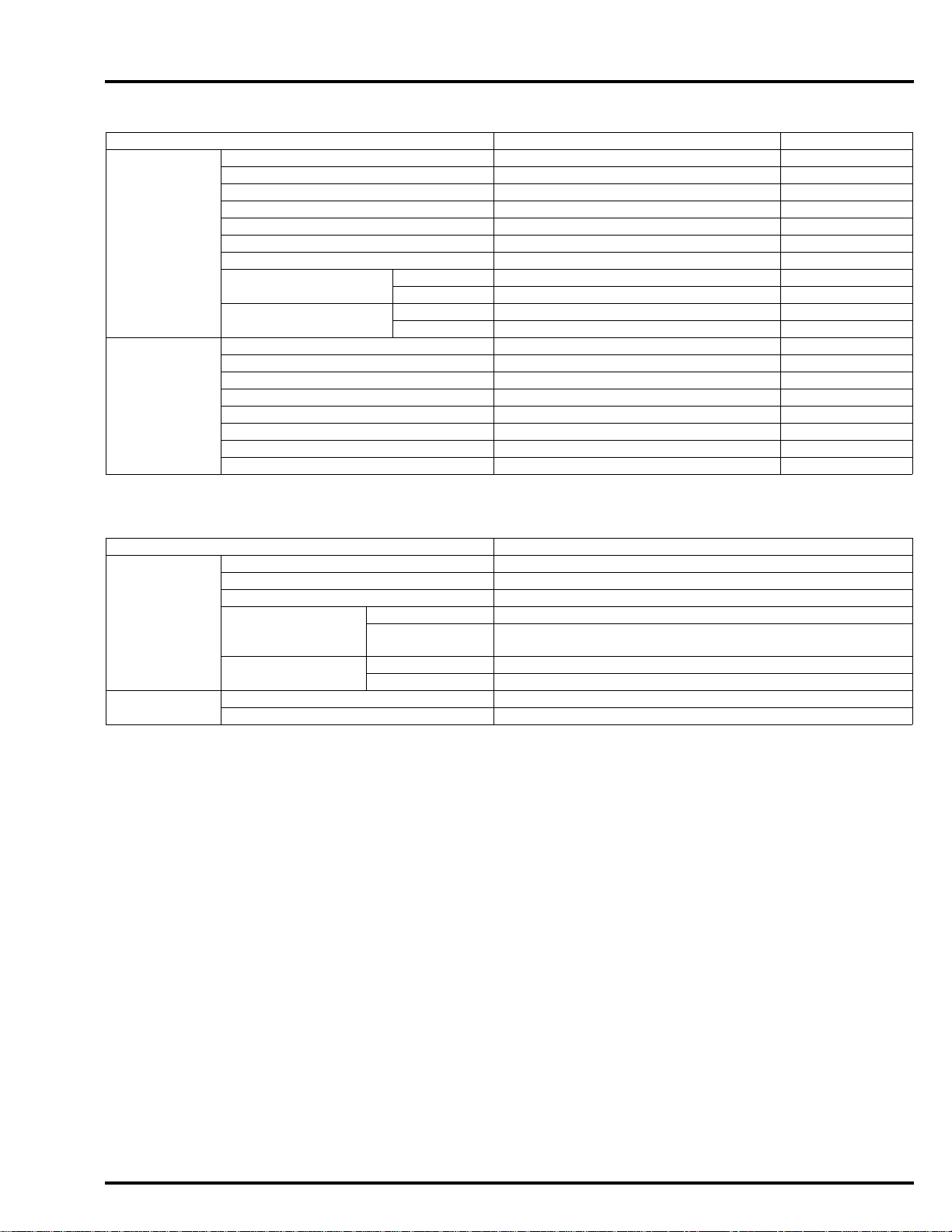
CLUTCH/GEARSHIFT LINKAGE SPECIFICATIONS (NC700X/XA/S/SA)
Unit: mm (in)
ITEM ST ANDARD SERVICE LIMIT
Clutch lever freeplay 10 – 20 (3/8 – 13/16) –
Clutch Spring free length 43.2 (1.70) 41.7 (1.64)
Disc thickness 2.62 – 2.78 (0.103 – 0.109) 2.3 (0.09)
Plate warpage – 0.30 (0.012)
Clutch outer guide I.D. 21.991 – 22.016 (0.8658 – 0.8668) 22.03 (0.867)
O.D. 31.959 – 31.975 (1.2582 – 1.2589) 31.92 (1.257)
Mainshaft O.D. at clutch outer guide 21.967 – 21.980 (0.8648 – 0.8654) 21.95 (0.864)
Clutch outer guide-to-mainshaft clearance 0.011 – 0.049 (0.0004 – 0.0019) 0.08 (0.003)
Primary driven gear I.D. 32.000 – 32.025 (1.2598 – 1.2608) 32.09 (1.263)
Primary driven gear-to-clutch outer guide clearance 0.025 – 0.066 (0.0010 – 0.0026) 0.10 (0.004)
DUAL CLUTCH TRANSMISSION SPECIFICATIONS (NC700XD/SD)
Unit: mm (in)
ITEM ST ANDARD SERVICE LIMIT
Clutch clearance 0.9 – 1.1 (0.035 – 0.043 ) 2.0 (0.08)
EOT sensor resistance (20°C/68°F) 2.5 – 2.8 k –
ALTERNATOR/STARTER CLUTCH SPECIFICATIONS
Unit: mm (in)
ITEM STANDARD SERVICE LIMIT
Starter driven gear boss O.D. 57.749 – 57.768 (2.2736 – 2.2743) 57.73 (2.273)
Starter clutch outer I.D. 74.412 – 74.442 (2.9296 – 2.9308) 74.46 (2.931)
CRANKCASE/TRANSMISSION/BALANCER SPECIFICATIONS
NC700X/XA/S/SA
Unit: mm (in)
ITEM ST ANDARD SERVICE LIMIT
Transmission Gear I.D. M5, M6, C1 28.000 – 28.021 (1.1024 – 1.1032) 28.04 (1.104)
C2, C3, C4 31.000 – 31.025 (1.2205 – 1.2215) 31.04 (1.222)
Shift fork,
fork shaft
Gear bushing
O.D.
Gear-to-bushing
clearance
Gear bushing I.D. M5 25.000 – 25.021 (0.9843 – 0.9851) 25.04 (0.986)
Mainshaft O.D. At M5 bushing 24.972 – 24.993 (0.9831 – 0.9840) 24.95 (0.982)
Countershaft O.D. At C2 bushing 27.967 – 27.980 (1.1011 – 1.1016) 27.95 (1.100)
Bushing-to-shaft
clearance
Fork I.D. 12.000 – 12.018 (0.4724 – 0.4731) 12.03 (0.474)
Claw thickness 5.93 – 6.00 (0.233 – 0.236) 5.9 (0.23)
Shift fork shaft O.D. 11.957 – 11.968 (0.4707 – 0.4712) 11.95 (0.470)
M5, M6 27.959 – 27.980 (1.1007 – 1.1016) 27.94 (1.100)
C2 30.955 – 30.980 (1.2187 – 1.2197) 30.93 (1.218)
C3, C4 30.950 – 30.975 (1.2185 – 1.2195) 30.93 (1.218)
M5, M6 0.020 – 0.062 (0.0008 – 0.0024) 0.08 (0.003)
C2 0.020 – 0.070 (0.0008 – 0.0028) 0.10 (0.004)
C3, C4 0.025 – 0.075 (0.0010 – 0.0030) 0.11 (0.004)
C2 27.985 – 28.006 (1.1018 – 1.1026) 28.02 (1.103)
M5 0.007 – 0.049 (0.0003 – 0.0020) 0.09 (0.004)
C2 0.005 – 0.039 (0.0002 – 0.0015) 0.06 (0.002)
1-10
Page 16
dummyheaddummyhead
GENERAL INFORMATION
NC700XD/SD
ITEM ST ANDARD SERVICE LIMIT
Transmission Gear I.D. M5 33.000 – 33.025 (1.2992 – 1.3002) 33.04 (1.301)
M6 43.000 – 43.025 (1.6929 – 1.6939) 43.04 (1.694)
C1 31.010 – 31.035 (1.2209 – 1.2218) 31.06 (1.223)
C2 25.000 – 25.021 (0.9843 – 0.9851) 25.03 (0.985)
C3, C4 31.000 – 31.025 (1.2205 – 1.2215) 31.04 (1.222)
Shift fork,
fork shaft
Gear bushing
O.D.
Gear-to-bushing
clearance
Gear bushing I.D. M5 29.985 – 30.006 (1.1805 – 1.1813) 30.03 (1.182)
Inner mainshaft
O.D.
Outer mainshaft
O.D.
Countershaft O.D. At C1 bushing 27.967 – 27.980 (1.1011 – 1.1016) 27.95 (1.100)
Bushing-to-shaft
clearance
Fork I.D. 12.000 – 12.018 (0.4724 – 0.4731) 12.03 (0.474)
Claw thickness 5.93 – 6.00 (0.233 – 0.236) 5.9 (0.23)
Shift fork shaft O.D. 11.957 – 11.968 (0.4707 – 0.4712) 11.95 (0.470)
M5 32.955 – 32.980 (1.2974 – 1.2984) 32.93 (1.296)
M6 42.950 – 42.975 (1.6909 – 1.6919) 42.93 (1.690)
C1 30.970 – 30.995 (1.2193 – 1.2203) 30.94 (1.218)
C2 24.959 – 24.980 (0.9826 – 0.9835) 24.94 (0.982)
C3, C4 30.950 – 30.975 (1.2185 – 1.2195) 30.93 (1.218)
M5 0.020 – 0.070 (0.0008 – 0.0028) 0.10 (0.004)
M6 0.025 – 0.075 (0.0010 – 0.0030) 0.11 (0.004)
C1 0.015 – 0.065 (0.0006 – 0.0026) 0.10 (0.004)
C2 0.020 – 0.062 (0.0008 – 0.0024) 0.09 (0.004)
C3, C4 0.025 – 0.075 (0.0010 – 0.0030) 0.11 (0.004)
M6 40.007 – 40.028 (1.5751 – 1.5759) 40.038 (1.5763)
C1 28.000 – 28.021 (1.1024 – 1.1032) 28.04 (1.104)
C2 21.985 – 22.006 (0.8655 – 0.8664) 22.02 (0.867)
At M5 bushing 29.957 – 29.970 (1.1794 – 1.1799) 29.93 (1.178)
At M6 bushing 39.975 – 39.991 (1.5738 – 1.5744) 39.965 (1.5734)
At C2 bushing 21.952 – 21.965 (0.8643 – 0.8648) 21.94 (0.864)
M5 0.015 – 0.049 (0.0006 – 0.0019) 0.09 (0.004)
M6 0.016 – 0.053 (0.0006 – 0.0021) 0.10 (0.004)
C1 0.020 – 0.054 (0.0008 – 0.0021) 0.08 (0.003)
C2 0.020 – 0.054 (0.0008 – 0.0021) 0.08 (0.003)
Unit: mm (in)
CRANKSHAFT/PISTON/CYLINDER SPECIFICATIONS
Unit: mm (in)
ITEM ST ANDARD SERVICE LIMIT
Crankshaft Connecting rod side clearance 0.15 – 0.35 (0.006 – 0.014) 0.45 (0.018)
Runout Right side – 0.03 (0.001)
Left side – 0.03 (0.001)
Main journal bearing oil clearance 0.019 – 0.037 (0.0007 – 0.0015) 0.05 (0.002)
Cylinder I.D. 73.000 – 73.015 (2.8740 – 2.8746) 73.07 (2.877)
Out-of-round – 0.10 (0.004)
Taper – 0.10 (0.004)
Warpage – 0.10 (0.004)
Piston, piston
rings
Cylinder-to-piston clearance 0.010 – 0.039 (0.0004 – 0.0015) 0.05 (0.002)
Connecting rod small end I.D. 17.964 – 17.977 (0.7072 – 0.7078) 17.985 (0.7081)
Crankpin bearing oil clearance 0.026 – 0.044 (0.0010 – 0.0017 ) 0.05 (0.002)
Piston O.D. at 13 mm (0.5 in) from
bottom
Piston pin bore I.D. 18.010 – 18.013 (0.7091 – 0.7092) 18.023 (0.7096)
Piston pin O.D. 17.996 – 18.000 (0.7 085 – 0.7087) 17.988 (0.7082)
Piston-to-piston pin clearance 0.010 – 0.017 (0.0004 – 0.0007) 0.035 (0.0014)
Piston ring end
gap
Piston ring-to-ring
groove clearance
Top 0.15 – 0.30 (0.006 – 0.012) 0.6 (0.02)
Second 0.30 – 0.42 (0.012 – 0.017) 0.6 (0.02)
Oil (side rail) 0.20 – 0.70 (0.008 – 0.028) 0.8 (0.03)
Top 0.035 – 0.080 (0.0014 – 0.0032) 0.15 (0.006)
Second 0.030 – 0.055 (0.0012 – 0.0022) 0.13 (0.005)
72.976 – 72.990 (2.8731 – 2.8736) 72.970 (2.8728)
1-11
Page 17
dummyheaddummyhead
GENERAL INFORMATION
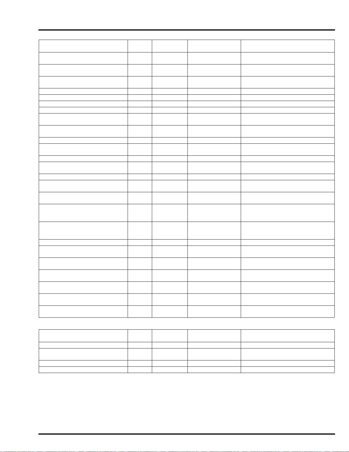
FRONT WHEEL/SUSPENSION/STEERING SPECIFICATIONS
ITEM ST ANDARD SERVICE LIMIT
Minimum tire tread depth – 1.5 (0.06)
Cold tire
pressure
Axle runout – 0.2 (0.01)
Wheel rim runout Radial – 2.0 (0.08)
Wheel balance weight
Fork Spring free
Driver only 250 kPa (2.50 kgf/cm
Driver and passenger 250 kPa (2.50 kgf/cm2, 36 psi) –
Axial – 2.0 (0.08)
length
Tube runout – 0.20 (0.008)
Recommended fork fluid Honda ULTRA CUSHION OIL SS-47
Fluid level NC700X/XA/XD 104 (4.1) –
Fluid capacity
NC700X/XA/XD 394.9 (15.55) 387.0 (15.24)
NC700S/SA/SD 357.0 (14.06) 349.9 (13.78)
(10W) or equivalent
NC700S/SA/SD 103 (4.1) –
NC700X/XA/XD
NC700S/SA/SD
514 ± 2.5 cm
0.09 Imp oz)
518 ± 2.5 cm
0.09 Imp oz)
3
(17.4 ± 0.08 US oz, 18.1 ±
3
(17.5 ± 0.08 US oz, 18.2 ±
2
, 36 psi) –
–
60 g (2.1 oz)
max.
Unit: mm (in)
–
–
–
REAR WHEEL/SUSPENSION SPECIFICATIONS
ITEM ST ANDARD SERVICE LIMIT
Minimum tire tread depth – 2.0 (0.08)
Cold tire pressure Driver only 290 kPa (2.90 kgf/cm
Driver and passenger 290 kPa (2.90 kgf/cm2, 42 psi) –
Axle runout – 0.2 (0.01)
Wheel rim runout Radial – 2.0 (0.08)
Axial – 2.0 (0.08)
Wheel balance weight
Drive
chain
Size/link NC700X/
XA/S/SA
NC700XD
/SD
Slack NC700X/XA/XD 30 – 40 (1.2 – 1.6) –
NC700S/SA/SD 25 – 35 (1.0 – 1.4) –
DID DID520V0-114LE –
RK RK520MKO-114LE –
DID DID520V0-112LE –
RK RK520MKO-112LE –
2
, 42 psi) –
–
60 g (2.1 oz)
max.
Unit: mm (in)
1-12
Page 18
dummyheaddummyhead
GENERAL INFORMATION
HYDRAULIC BRAKE SPECIFICATIONS
ITEM ST ANDARD SERVICE LIMIT
Front Specified brake fluid DOT 4 –
Brake disc thickness 4.8 – 5.2 (0.19 – 0.20) 4.0 (0.16)
Brake disc warpage – 0.30 (0.012)
Master cylinder I.D. 11.000 – 11.043 (0.4331 – 0.4348) 11.055 (0.43 52)
Master piston O.D. 10.957 – 10.984 (0.4314 – 0.4324) 10.945 (0.4309)
Caliper cylinder I.D. (NC700X/S) 27.000 – 27.050 (1.0630 – 1.0650) 27.060 (1.0654)
Caliper piston O.D. (NC700X/S) 26.918 – 26.968 (1.0598 – 1.0617) 26.91 (1.059)
Caliper cylinder I.D.
(NC700XA/XD/SA/SD)
Caliper piston O.D.
(NC700XA/XD/SA/SD)
Rear Specified brake fluid DOT 4 –
Brake disc thickness 4.8 – 5.2 (0.19 – 0.20) 4.0 (0.16)
Brake disc warpage – 0.30 (0.012)
Master cylinder I.D. 14.000 – 14.043 (0.5512 – 0.5529) 14.055 (0.55 33)
Master piston O.D. 13.957 – 13.984 (0.5495 – 0.5506) 13.945 (0.5490)
Caliper cylinder I.D. 38.18 – 38.23 (1.503 – 1.505) 38.24 (1.506)
Caliper piston O.D. 38.098 – 38.148 (1.4999 – 1.5019) 38.09 (1.500)
Brake pedal height 85.0 – 87.0 (3.35 – 3.43) –
Cylinder A 22.650 – 22.700 (0.8917 – 0.8937) 22.712 (0.8941)
Cylinder B 27.000 – 27.050 (1.0630 – 1.0650) 27.060 (1.0654)
Piston A 22.585 – 22.618 (0.8892 – 0.8905) 22.56 (0.888)
Piston B 26.918 – 26.968 (1.0598 – 1.0617) 26.91 (1.059)
Unit: mm (in)
BATTERY/CHARGING SYSTEM SPECIFICATIONS
ITEM SPECIFICATIONS
Battery Type YTZ12S
Capacity 12 V – 11 Ah
Current leakage 1.2 mA maximum
Voltage
(20°C/68°F)
Charging current Normal 1.1 A/5 – 10 h
Alternator Capacity 0.42 kW/5,000 min
Charging coil resistance (20°C/68°F) 0.1 – 0.5
Fully charged 13.0 – 13.2 V
Needs
charging
Quick 5.5 A/1 h
Below 12.4 V
-1
(rpm)
1-13
Page 19
dummyheaddummyhead
GENERAL INFORMATION
LIGHTS/METERS/SWITCHES SPECIFICATIONS
ITEM SPECIFICATIONS
Bulbs Headlight 12 V – 60/55 W
Position light 12 V – 5 W
Brake/tail/license light 12 V – 21/5 W
Turn signal light 12 V – 21 W x 4
Instrument light LED
Turn signal indicator LED
High beam indicator LED
Neutral indicator LED
Engine oil pressure indicator LED
High coolant temperature indicator LED
MIL LED
HISS indicator LED
ABS indicator (NC700XA/XD/SA/SD) LED
Parking brake indicator (NC700XD/SD) LED
Fuse Main fuse 30 A
PGM-FI fuse 15 A
Sub fuse 15 A x 2, 7.5 A x 4
ABS fuse (NC700XA/XD/SA/SD) 30 A x 2, 7.5 A
DCT fuse (NC700XD/SD) 30 A, 7.5 A
ECT sensor resistance 40°C (104°F ) 1.0 – 1.3 k
100°C (212°F) 0.1 – 0.2 k
Fuel level sensor resistance Full 4 – 6
Empty 80 – 83
1-14
Page 20
dummyheaddummyhead
TORQUE VALUES
STANDARD TORQUE VALUES
GENERAL INFORMATION
FASTENER TYPE
5 mm bolt and nut 5.2 (0.5, 3.8) 5 mm screw 4.2 (0.4, 3.1)
6 mm bolt (Include SH flange bolt)
and nut
8 mm bolt and nut 22 (2.2, 16)
10 mm bolt and nut 34 (3.5, 25) 8 mm flange bolt and nut 27 (2.8, 20)
12 mm bolt and nut 54 (5.5, 40) 10 mm flange bolt and nut 39 (4.0, 29)
TORQUE
N·m (kgf·m, lbf·ft) N·m (kgf·m, lbf·ft)
10 (1.0, 7) 6 mm screw 9.0 (0.9, 6.6)
6 mm flange bolt (Include NSHF) and
nut
FASTENER TYPE
TORQUE
12 (1.2, 9)
ENGINE & FRAME TORQUE VALUES
FRAME BODY PANELS/EXHAUST SYSTEM
ITEM Q'TY
Seat cowl assembly screw 2 4 0.9 (0.1, 0.7)
Brake/tail/license light mounting
socket bolt
Reflector mounting nut 1 5 1.7 (0.2, 1.3)
Turn signal light mounting screw 4 6 2.5 (0.3, 1.8)
Luggage box lid assembly screw 9 4 0.9 (0.1, 0.7)
Luggage box lid lock plate
mounting screw
Luggage box lid mounting socket
bolt
Luggage box lid hinge nut 1 6 12 (1.2, 9) U-nut
Gearshift arm pinch bolt
(NC700X/XA/S/SA)
Muffler cover socket bolt 1 6 10 (1.0, 7)
Muffler band bolt 1 8 17.5 (1.8, 13)
Exhaust pipe joint nut 3 8 28 (2.9, 21) See page 2-34
Exhaust pipe stud bolt 3 8 – See page 2-35
1 6 10 (1.0, 7)
2 6 4.0 (0.4, 3.0)
3 6 12 (1.2, 9)
1 6 12 (1.2, 9) ALOC bolt; replace with a new one.
THREAD TORQUE
DIA. (mm) N·m (kgf·m, lbf·ft)
REMARKS
1-15
Page 21
dummyheaddummyhead
GENERAL INFORMATION
MAINTENANCE
ITEM Q'TY
Air cleaner housing cover screw 6 5 1.1 (0.1, 0.8)
Spark plug 2 14 22 (2.2, 16)
Valve adjusting screw lock nut 8 7 14 (1.4, 10) Apply engine oil to the threads and
Camshaft maintenance cap 1 36 4.0 (0.4, 3.0) See page 3-12
Timing hole cap 1 14 10 (1.0, 7) Apply grease to the threads.
Crankshaft hole cap 1 30 15 (1.5, 11) Apply grease to the threads.
Engine oil drain bolt 1 12 30 (3.1, 22)
Engine oil filter cartridge 1 20 26 (2.7, 19) Apply engine oil to the threads.
Oil filter boss 1 20 – See page 3-14
Rear axle nut 1 18 98 (10.0, 72) U-nut
Drive chain adjuster lock nut 2 8 21 (2.1, 15)
Drive sprocket bolt 1 10 54 (5.5, 40)
Driven sprocket nut 5 12 108 (11.0, 80) U-nut
Master cylinder reservoir cover
screw
Rear brake reservoir mounting bolt 1 6 10 (1.0, 7)
Rear master cylinder push rod lock
nut
Parking brake adjuster bolt lock
nut (NC700XD/SD)
Sidestand pivot bolt 1 10 – See page 3-27
Sidestand pivot nut 1 10 39 (4.0, 29) U-nut
Sidestand switch bolt 1 6 10 (1.0, 7) ALOC bolt; replace with a new one.
4 4 1.5 (0.2, 1.1)
1 8 17 (1.7, 13)
1 8 17 (1.7, 13)
THREAD TORQUE
DIA. (mm) N·m (kgf·m, lbf·ft)
REMARKS
seating surface.
Apply locking agent to the threads.
Coating width; 6.5 ± 1.0 mm (0.26 ±
0.04 in) from tip
Apply grease to the sliding surface.
PGM-FI SYSTEM
ITEM Q'TY
ECT sensor 1 10 12 (1.2, 9)
Bank angle sensor mounting bolt 2 6 10 (1.0, 7)
O2 sensor 1 12 24.5 (2.5, 18)
IGNITION SYSTEM
ITEM Q'TY
Timing hole cap 1 14 10 (1.0, 7) Apply grease to the threads.
Right crankcase cover wire clamp
bolt (NC700XD/SD)
ELECTRIC STARTER
ITEM Q'TY
Starter motor terminal nut 1 6 10 (1.0, 7)
FUEL SYSTEM
ITEM Q'TY
Fuel pump mounting nut 6 6 12 (1.2, 9) For tightening sequence (page 7-14)
Air cleaner connecting hose band
screw
Insulator band screw 2 5 – See page 7-18
2 6 12 (1.2, 9) Apply locking agent to the threads.
1 4 1.5 (0.2, 1.1)
THREAD TORQUE
DIA. (mm) N·m (kgf·m, lbf·ft)
THREAD TORQUE
DIA. (mm) N·m (kgf·m, lbf·ft)
THREAD TORQUE
DIA. (mm) N·m (kgf·m, lbf·ft)
THREAD TORQUE
DIA. (mm) N·m (kgf·m, lbf·ft)
REMARKS
REMARKS
Coating width; 6.5 ± 1.0 mm (0.26 ±
0.04 in) except 2.0 ± 1.0 mm (0.08 ±
0.04 in) from tip
REMARKS
REMARKS
1-16
Page 22
dummyheaddummyhead
GENERAL INFORMATION
COOLING SYSTEM
ITEM Q'TY
Water hose band screw 6 – – See page 8-9
Fan motor shroud mounting bolt 3 6 8.4 (0.9, 6.2)
Fan motor mounting screw 3 4 2.7 (0.3, 2.0)
Cooling fan mounting nut 1 3 1.0 (0.1, 0.7) Apply locking agent to the threads.
LUBRICATION SYSTEM
ITEM Q'TY
Engine oil filter cartridge 1 20 26 (2.7, 19) Apply engine oil to the threads.
CYLINDER HEAD/VALVES
ITEM Q'TY
Cylinder head cover socket bolt 3 6 10 (1.0, 7)
Breather plate mounting bolt 8 6 12 (1.2, 9) Apply locking agent to the threads.
Rocker arm shaft bolt 3 8 29 (3.0 , 21) Apply engine oil to the threads and
Camshaft maintenance cap 1 36 4.0 (0.4 , 3.0) See page 10-11
Cam chain tensioner bolt 2 6 12 (1.2, 9)
Cam sprocket bolt 1 10 56 (5.7, 41) Apply engine oil to the threads and
Water hose band screw 6 – – See page 10-16
Insulator band screw 1 5 – See page 10-25
Cylinder head special bolt 6 9 44 (4.5, 32) Apply molybdenum oil solution to the
THREAD TORQUE
DIA. (mm) N·m (kgf·m, lbf·ft)
THREAD TORQUE
DIA. (mm) N·m (kgf·m, lbf·ft)
THREAD TORQUE
DIA. (mm) N·m (kgf·m, lbf·ft)
REMARKS
See page 8-10
See page 8-14
REMARKS
REMARKS
Coating width; 6.5 ± 1.0 mm (0.26 ±
0.04 in) except 2.0 ± 1.0 mm (0.08 ±
0.04 in) from tip
seating surface.
See page 10-28
seating surface.
threads and seating surface.
CLUTCH/GEARSHIFT LINKAGE (NC700X/XA/S/SA)
ITEM Q'TY
Clutch center lock nut 1 18 128 (13.1, 94) Apply engine oil to the threads and
Clutch lifter plate bolt 4 6 12 (1.2, 9)
Primary drive gear mounting bolt 1 10 93 (9.5, 69) Apply engine oil to the threads and
Shift drum stopper arm pivot bolt 1 6 12 (1.2, 9) Apply locking agent to the threads.
Shift drum center socket bolt 1 8 23 (2.3, 17) Apply locking agent to the threads.
Gearshift pedal adjuster lock nut 2 6 10 (1.0, 7)
Gearshift pedal pivot bolt 1 8 27 (2.8, 20)
THREAD TORQUE
DIA. (mm) N·m (kgf·m, lbf·ft)
REMARKS
seating surface.
Lock nut; replace with a new one and
stake.
seating surface.
Coating width; 6.5 ± 1.0 mm (0.26 ±
0.04 in) except 2.0 ± 1.0 mm (0.08 ±
0.04 in) from tip
Coating width; 6.5 ± 1.0 mm (0.26 ±
0.04 in) except 2.0 ± 1.0 mm (0.08 ±
0.04 in) from tip
1-17
Page 23
dummyheaddummyhead
GENERAL INFORMATION
DUAL CLUTCH TRANSMISSION (DCT) (NC700XD/SD)
ITEM Q'TY
Solenoid valve stopper plate bolt 1 6 12 (1.2, 9) Apply locking agent to the threads.
Right crankcase cover wire clamp
bolt
Linear solenoid valve body
mounting bolt
Shift spindle angle sensor bolt 1 6 12 (1.2, 9)
Primary drive gear mounting bolt 1 10 93 (9.5, 69) Apply engine oil to the threads and
Reduction gear cover bolt 3 6 14 (1.4, 10)
TR sensor bolt 1 6 12 (1.2, 9)
Shift control motor bolt 3 6 14 (1.4, 10)
Shift drum center bolt 1 8 23 (2.3, 17) Apply locking agent to the threads.
Drum shifter guide plate bolt 2 6 12 (1.2, 9) Apply locking agent to the threads.
Clutch line EOP sensor 3 10 19.6 (2.0, 14)
EOT sensor 1 10 14 (1.4, 10) Apply engine oil to the threads and
2 6 12 (1.2, 9) Apply locking agent to the threads.
6 6 – For tightening sequence (page 12-
THREAD TORQUE
DIA. (mm) N·m (kgf·m, lbf·ft)
REMARKS
Coating width: 6.5 ± 1.0 mm (0.26 ±
0.04 in) except 2.0 ± 1.0 mm (0.08 ±
0.04 in) from tip
Coating width: 6.5 ± 1.0 mm (0.26 ±
0.04 in) except 2.0 ± 1.0 mm (0.08 ±
0.04 in) from tip
101)
seating surface.
Coating width: 6.5 ± 1.0 mm (0.26 ±
0.04 in) except 2.0 ± 1.0 mm (0.08 ±
0.04 in) from tip
Coating width: 6.5 ± 1.0 mm (0.26 ±
0.04 in) except 2.0 ± 1.0 mm (0.08 ±
0.04 in) from tip
seating surface.
ALTERNATOR/STARTER CLUTCH
ITEM Q'TY
Flywheel mounting bolt 1 12 157 (16.0, 116) Left hand thread
Starter clutch socket bolt 6 8 30 (3.1, 22) Apply locking agent to the threads.
Alternator stator mounting bolt 4 6 10 (1.0, 7) Apply locking agent to the threads.
Alternator wire clamp bolt 1 6 10 (1.0, 7) Apply locking agent to the threads.
THREAD TORQUE
DIA. (mm) N·m (kgf·m, lbf·ft)
REMARKS
Apply engine oil to the threads and
seating surface.
Coating width; 6.5 ± 1.0 mm (0.26 ±
0.04 in) except 2.0 ± 1.0 mm (0.08 ±
0.04 in) from tip
Coating width; 6.5 ± 1.0 mm (0.26 ±
0.04 in) except 2.0 ± 1.0 mm (0.08 ±
0.04 in) from tip
Coating width; 6.5 ± 1.0 mm (0.26 ±
0.04 in) except 2.0 ± 1.0 mm (0.08 ±
0.04 in) from tip
1-18
Page 24
dummyheaddummyhead
GENERAL INFORMATION
CRANKCASE/TRANSMISSION/BALANCER
ITEM Q'TY
Mainshaft bearing set plate bolt 3 6 12 (1.2, 9) Apply locking agent to the threads.
Shift drum bearing set plate bolt 2 6 12 (1.2, 9) Apply locking agent to the threads.
Balancer shaft bearing set plate
bolt
Crankcase main journal bolt (new) 6 9 20 (2.0, 15) + 150° See page 14-30
Crankcase 10 mm bolt 1 10 39 (4.0, 29)
Crankcase 8 mm bolt 3 8 24 (2.4, 18)
Crankcase 8 x 45 mm bolt 1 8 24 (2.4, 18) Apply locking agent to the threads.
Crankcase 6 mm bolt 8 6 12 (1.2, 9)
3 6 12 (1.2, 9) Apply locking agent to the threads.
THREAD TORQUE
DIA. (mm) N·m (kgf·m, lbf·ft)
REMARKS
Coating width; 6.5 ± 1.0 mm (0.26 ±
0.04 in) except 2.0 ± 1.0 mm (0.08 ±
0.04 in) from tip
Coating width; 6.5 ± 1.0 mm (0.26 ±
0.04 in) except 2.0 ± 1.0 mm (0.08 ±
0.04 in) from tip
Coating width; 6.5 ± 1.0 mm (0.26 ±
0.04 in) except 2.0 ± 1.0 mm (0.08 ±
0.04 in) from tip
Replace with a new one.
Coating width; 6.5 ± 1.0 mm (0.26 ±
0.04 in) from tip
CRANKSHAFT/PISTON/CYLINDER
ITEM Q'TY
Crankpin bearing cap bolt 4 6 10 (1.0, 7) + 90° See page 15-7
Crankcase main journal bolt
(retightening)
ENGINE REMOVAL/INSTALLATION
ITEM Q'TY
Rear lower engine hunger nut 1 12 59 (6.0, 44)
Front lower engine hunger bolt 2 12 54 (5.5, 40 )
Upper engine hunger bolt 2 12 54 (5.5, 40)
Rear upper engine hunger nut 1 12 54 (5.5, 40)
Step holder mounting socket bolt 4 8 32 (3.3, 24)
Drive sprocket bolt 1 10 54 (5.5, 40)
Starter motor terminal nut 1 6 10 (1.0, 7)
Water hose band screw 2 – – See page 16-18
6 9 20 (2.0, 15) + 120° See page 15-9
THREAD TORQUE
DIA. (mm) N·m (kgf·m, lbf·ft)
See page 15-12
Replace with a new one.
Apply engine oil to the threads and
seating surface.
Apply engine oil to the threads and
seating surface.
THREAD TORQUE
DIA. (mm) N·m (kgf·m, lbf·ft)
See page 16-19
See page 16-24
See page 16-25
REMARKS
REMARKS
1-19
Page 25
dummyheaddummyhead
GENERAL INFORMATION
FRONT WHEEL/SUSPENSION/STEERING
ITEM Q'TY
Handlebar holder bolt 4 8 22 (2.2, 16)
Handlebar switch housing screw 4 5 2.5 (0.3, 1.8)
Front master cylinder holder bolt 2 6 12 (1.2, 9)
Handlebar weight mounting screw 2 6 10 (1.0, 7) ALOC screw; replace with a new
Front brake disc mounting bolt 5 8 42 (4.3, 31) ALOC bolt; replace with a new one.
Front axle 1 18 74 (7.5, 55) Apply grease to the sliding surface.
Front axle pinch bolt 1 8 22 (2.2, 16)
Fork socket bolt 2 8 20 (2.0, 15) Apply locking agent to the threads.
Bottom bridge pinch bolt 2 10 39 (4.0, 29)
Fork cap 2 37 22 (2.2, 16)
Top bridge pinch bolt 2 8 22 (2.2, 16)
Front brake caliper mounting bolt 2 8 30 (3.1, 22) ALOC bolt; replace with a new one.
Steering stem adjusting nut 1 26 23 (2.3, 17) See page 17-38
Steering stem adjusting lock nut 1 26 – See page 17-38
Steering stem nut 1 24 103 (10.5, 76) See page 17-38
Clutch lever pivot bolt
(NC700X/XA/S/SA)
Clutch lever pivot nut
(NC700X/XA/S/SA)
1 6 1.0 (0.1, 0.7) Apply grease to the slidin g surface.
1 6 6.0 (0.6, 4.4)
THREAD TORQUE
DIA. (mm) N·m (kgf·m, lbf·ft)
REMARKS
one.
Apply engine oil to the threads.
REAR WHEEL/SUSPENSION
ITEM Q'TY
Driven sprocket nut 5 12 108 (11.0, 80) U-nut
Rear brake disc mounting bolt 5 8 42 (4.3, 31) ALOC bolt; replace with a new one.
Rear axle nut 1 18 98 (10.0, 72) U-nut
Shock absorber mounting nut 2 10 44 (4.5, 32) U-nut
Shock arm nut 1 10 44 (4.5, 32) U-nut
Shock link nut 2 10 44 (4.5, 32) U-nut
Drive chain slider mounting screw 2 5 5.9 (0.6, 4.4)
Swingarm pivot nut 1 18 98 (10.0, 72) U-nut
Step holder mounting socket bolt 4 8 32 (3.3, 24)
Gearshift arm pinch bolt
(NC700X/XA/S/SA)
1 6 12 (1.2, 9) ALOC bolt; replace with a new one.
THREAD TORQUE
DIA. (mm) N·m (kgf·m, lbf·ft)
REMARKS
1-20
Page 26
dummyheaddummyhead
GENERAL INFORMATION
HYDRAULIC BRAKE
ITEM Q'TY
Brake caliper bleed valve
(NC700X/S)
Brake caliper bleed valve
(NC700XA/XD/SA/SD)
Master cylinder reservoir cover
screw
Rear brake reservoir mounting bolt 1 6 10 (1.0, 7)
Brake pad pin 2 10 17 (1.7, 13)
Rear brake caliper mounting bolt 1 8 22 (2.2, 16) ALOC bolt; replace with a new one.
Front master cylinder holder bolt 2 6 12 (1.2, 9)
Brake hose oil bolt
(NC700X/S)
Brake hose oil bolt
(NC700XA/XD/SA/SD)
Front brake light switch screw 1 4 1.2 (0.1, 0.9)
Front brake lever pivot bolt 1 6 1.0 (0.1, 0.7) Apply 0.10 g (0.004 oz) silicone
Front brake lever pivot nut 1 6 5.9 (0.6, 4.4)
Rear master cylinder mounting
bolt
Step holder mounting socket bolt 4 8 32 (3.3, 24)
Rear master cylinder hose joint
screw
Rear master cylinder push rod lock
nut
Front brake caliper pin 1 8 22 (2.2, 16) Apply locking agent to the threads.
Front brake caliper bracket pin 1 8 12 (1.2, 9) Apply locking agent to the threads.
Front brake caliper mounting bolt 2 8 30 (3.1, 22) ALOC bolt; replace with a new one.
Rear brake caliper pin 1 12 27 (2.8, 20) Ap ply 0.4 g (0.01 oz) silicone grease
Parking brake caliper mounting
bolt (NC700XD/SD)
Parking brake caliper pin bolt
(NC700XD/SD)
Parking brake pad pin
(NC700XD/SD)
Parking brake adjuster bolt lock
nut (NC700XD/SD)
Parking brake cable mounting nut
(NC700XD/SD)
2 8 5.4 (0.6, 4.0)
3 8 5.4 (0.6, 4.0)
4 4 1.5 (0.2, 1.1)
4 10 34 (3.5, 25)
5 10 34 (3.5, 25)
2 6 12 (1.2, 9)
1 4 1.5 (0.2, 1.1) Apply lockin g agent to the threads.
1 8 17 (1.7, 13)
2 8 31 (3.2, 23) ALOC bolt; replace with a new one.
1 8 22 (2.2, 16) A pply locking agent to the threads.
2 8 17 (1.7, 13) ALOC bolt; replace with a new one.
1 8 17 (1.7, 13)
1 10 10 (1.0, 7)
THREAD TORQUE
DIA. (mm) N·m (kgf·m, lbf·ft)
REMARKS
grease to the sliding surface.
Apply 0.4 g (0.01 oz) silicone grease
to the sliding surface.
Apply 0.4 g (0.01 oz) silicone grease
to the sliding surface.
to the sliding surface.
ANTI-LOCK BRAKE SYSTEM (ABS) (NC700XA/XD/SA/SD)
ITEM Q'TY
Step holder mounting socket bolt 4 8 32 (3.3, 24)
Brake pipe joint nut 14 10 14 (1.4, 10) Apply brake fluid to the threads and
PCV mounting bolt 2 6 12 (1.2, 9)
Delay valve mounting bolt 2 6 12 (1.2, 9)
THREAD TORQUE
DIA. (mm) N·m (kgf·m, lbf·ft)
REMARKS
sliding surface.
1-21
Page 27
dummyheaddummyhead
GENERAL INFORMATION
LIGHTS/METERS/SWITCHES
ITEM Q'TY
Turn signal light mounting screw 4 6 2.5 (0.3, 1.8)
Combination meter mounting
screw
Combination meter back cover
mounting screw (NC700S/SA/SD)
EOP switch 1 PT 1/8 18 (1.8, 13) Apply sealant to the threads.
Ignition switch mounting bolt 2 8 25 (2.5, 18) One way bolt; replac e with a new
Neutral switch 1 10 12 (1.2, 9)
Parking brake switch screw
(NC700XD/SD)
OTHERS
ITEM Q'TY
Cam chain tensioner set plate bolt 1 6 12 (1.2, 9) Apply locking agent to the threads.
Camshaft cap 1 20 30 (3.1, 22)
Gearshift spindle return spring pin 1 8 23 (2.3, 17)
Main step rubber mounting bolt 2 5 5.1 (0.5, 3.8) ALOC bolt; replace with a new one.
Main step cap bolt 2 6 12 (1.2, 9)
3 5 1.0 (0.1, 0.7)
4 3 0.3 (0.03, 0.2)
1 4 1.2 (0.1, 0.9)
THREAD TORQUE
DIA. (mm) N·m (kgf·m, lbf·ft)
THREAD TORQUE
DIA. (mm) N·m (kgf·m, lbf·ft)
REMARKS
one.
REMARKS
Coating width; 6.5 ± 1.0 mm (0.26 ±
0.04 in) except 2.0 ± 1.0 mm (0.08 ±
0.04 in) from tip
1-22
Page 28
dummyheaddummyhead
GENERAL INFORMATION
LUBRICATION & SEAL POINTS
ENGINE
MA TERIAL LOCA TION REMARKS
Liquid sealant
(Three Bond 1207B or
equivalent)
Molybdenum oil solution
(a mixture of 1/2 engine oil
and 1/2 molybdenum
disulfide grease)
Engine oil Oil filter cartridge O-ring
Multi-purpose grease Each oil seal lips
Locking agent CKP sensor mounting bolt threads Coating width; 6.5 ± 1.0
Templex N3 grease (ESSO) Electric shift reduction gear teeth and journal (NC700XD/SD) 2 – 4 g (0.07 – 0.14 oz)
Oil pan mating surface See page 9-12
Right crankcase cover mating surface See page 11-6
CKP sensor wire grommet
Linear solenoid valve wire grommet (NC700XD/SD)
Alternator wire grommet
Alternator cover mating surface See page 13-7
Crankcase mating surface See page 14-28
Rocker arm sliding surface
Rocker arm shaft outer surface
Camshaft lobes, journals and thrust surface
Valve stem (valve guide sliding surface) and stem end
Clutch outer guide sliding surface (NC700X/XA/S/SA)
Starter reduction and idle gear shaft outer surface
M3/4, C5, C6 gear (shift fork grooves) (NC700X/XA/S/SA)
M3, M4, C5, C6 gear (shift fork grooves) (NC700XD/SD)
Each transmission spline collar outer surface
Each transmission collar inner and outer surface
Shift fork guide area and guide pin
Shift fork shaft outer surface
Main journal bearing sliding surface
Crankpin bearing sliding surface
Crankshaft thrust surface
Oil filler cap O-ring
Timing hole cap O-ring
Crankshaft hole cap O-ring
Clutch oil filter cover O-ring (NC700XD/SD)
Oil joint pipe O-ring (NC700XD/SD)
Clutch oil guide collar O-rings (NC700XD/SD)
Oil strainer seal ring
Starter motor O-ring
Injector seal ring
Water pump large O-ring
Valve stem seal
Clutch disc entire surface (NC700X/XA/S/SA)
Clutch lifter rod A sliding surface (NC700X/XA/S/SA)
Clutch lifter rod B sliding surface (NC700X/XA/S/SA)
Mainshaft seal rings (NC700XD/SD)
Starter one-way clutch
Piston sliding surface
Piston ring sliding surface
Piston pin outer surface
Each bearing
Each gear teeth and rotating surface
Each O-ring (except water sealing)
Other rotating area and sliding surface
mm (0.26 ± 0.04 in)
except 2.0 ± 1.0 mm (0.08
± 0.04 in) from tip
1-23
Page 29
dummyheaddummyhead
GENERAL INFORMATION
FRAME
MA TERIAL LOCATION REMARKS
Urea based multi-purpose
grease with extreme
pressure
(example: Kyodo Yushi
EXCELITE EP2, Shell
Stamina EP2 or equivalent)
Molybdenum disulfide grease Shock arm needle bearings
Multi-purpose grease Seat catch hook sliding area
Cable lubricant Seat lock cable inside
Honda bond A, Cemedine
#540 or equivalent
Silicone grease Front brake lever sliding surface and lever-to-master piston
DOT 4 brake fluid Brake caliper piston and piston seals
Fork fluid Fork cap O-ring
Drive chain lubricant
designed specifically for use
with O-ring chains, #80 – 90
gear oil or equivalent
Steering head bearing sliding surface 3 – 5 g (0.1 – 0.2 oz)
Steering head dust seal lips
Rear shock absorber needle bearing
Rear shock absorber dust seal lips
Swingarm pivot needle bearings
Swingarm pivot ball bearing
Swingarm pivot dust seal lips
Luggage box lid catch sliding area
Gearshift pedal pivot and dust seal lips (NC700X/XA/S/SA)
Gearshift pedal tie-rod ball joint area (NC700X/XA/S/SA)
Throttle cable end and throttle grip pipe flange groove
Front wheel dust seal lips
Rear wheel hub O-ring
Rear wheel dust seal lips
Rear axle sliding surface
Swingarm pivot sliding surface
Rear brake pedal pivot sliding area
Parking brake ratchet A, B teeth and sliding surface
(NC700XD/SD)
Parking brake lever, washer sliding surface (NC700XD/SD)
Parking brake switch spring sliding surface (NC700XD/SD)
Main step sliding area
Pillion step sliding area
Luggage box lid lock cable inside
Throttle cable A, B inside
Clutch cable inside (NC700X/XA/S/SA)
Parking brake cable inside (NC700XD/SD)
Handlebar grip rubber inside
Brake pad retainer mating surface
contacting area
Rear brake master cylinder push rod sliding surface and boot
fitting area
Brake caliper dust seals
Rear brake caliper boot inside 0.4 g (0.01 oz)
Brake pad pin stopper ring
Parking brake shaft outer surface (NC700XD/SD) 0.4 g (0.01 oz) minimum
Parking brake adjuster bolt threads and caliper piston sliding
surface (NC700XD/SD)
Parking brake shaft boot lips (NC700XD/SD) 0.4 g (0.01 oz) minimum
Parking brake caliper bracket pin sliding surface (NC700XD/
SD)
Parking brake caliper sleeve sliding surface (NC700XD/SD) 0.4 g (0.01 oz) minimum
Brake master piston and cups
Brake master cylinder inside
Rear master cylinder reservoir hose joint O-ring
Fork dust seal and oil seal lips
Drive chain whole surface
0.10 g (0.004 oz)
0.4 g (0.01 oz) minimum
0.4 g (0.01 oz) minimum
1-24
Page 30
dummyheaddummyhead
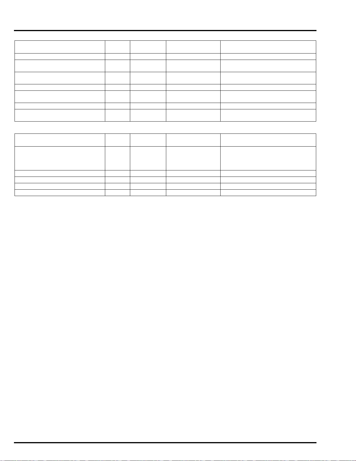
RIGHT HANDLEBAR
SWITCH WIRE
LEFT HANDLEBAR
SWITCH WIRE
CLUTCH SWITCH WIRE
BRAKE LIGHT SWITCH
CONNECTOR
RIGHT HANDLEBAR
SWITCH WIRE
LEFT HANDLEBAR
SWITCH WIRE
BRAKE LIGHT SWITCH
CONNECTOR
RIGHT HANDLEBAR
SWITCH WIRE
THROTTLE CABLE B
THROTTLE CABLE A
CABLE & HARNESS ROUTING
NC700X/XA:
GENERAL INFORMATION
NC700XD:
1-25
Page 31

dummyheaddummyhead
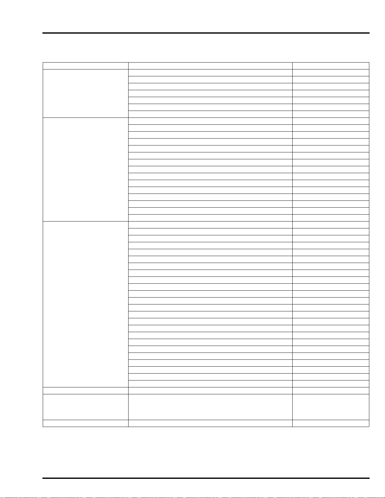
RIGHT HANDLEBAR
SWITCH WIRE
LEFT HANDLEBAR
SWITCH WIRE
CLUTCH SWITCH WIRE
BRAKE LIGHT SWITCH
CONNECTOR
RIGHT HANDLEBAR
SWITCH WIRE
LEFT HANDLEBAR
SWITCH WIRE
BRAKE LIGHT SWITCH
CONNECTOR
RIGHT HANDLEBAR
SWITCH WIRE
THROTTLE CABLE A
THROTTLE CABLE B
GENERAL INFORMATION
NC700S/SA:
NC700SD:
1-26
Page 32

dummyheaddummyhead
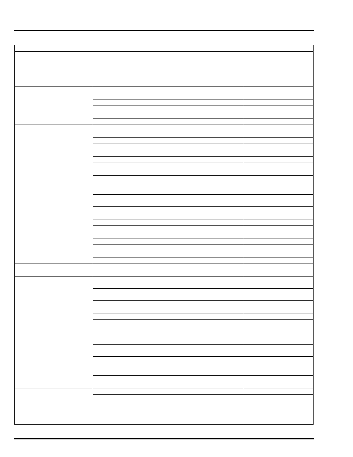
FRONT SUB HARNESS
FRONT LEFT TURN SIGNAL LIGHT
3P (ORANGE) CONNECTOR
FRONT RIGHT TURN SIGNAL LIGHT
3P (BLUE) CONNECTOR
POSITION
LIGHT WIRE
FRONT SUB HARNESS
6P (BROWN) CONNECTOR
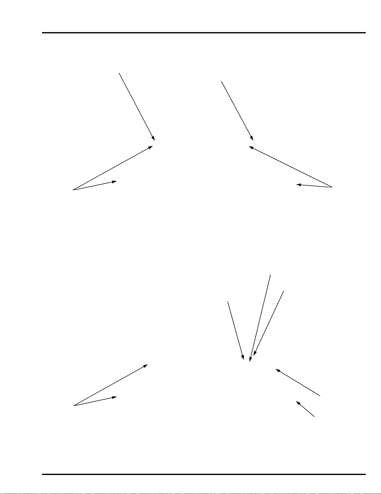
FRONT SUB HARNESS
FRONT LEFT TURN SIGNAL LIGHT
3P (ORANGE) CONNECTOR
FRONT RIGHT TURN SIGNAL LIGHT
3P (BLUE) CONNECTOR
FRONT SUB HARNESS
6P (BROWN) CONNECTOR
POSITION
LIGHT WIRES
NC700X/XA/XD:
GENERAL INFORMATION
NC700S/SA/SD:
1-27
Page 33

dummyheaddummyhead
CLUTCH CABLE
LEFT HANDLEBAR
SWITCH WIRE
FRONT SUB HARNESS
6P (BROWN) CONNECTOR
HEADLIGHT
3P (BLACK) CONNECTOR
LEFT HANDLEBAR SWITCH
10P (GRAY) CONNECTOR
IGNITION SWITCH
2P (BROWN) CONNECTOR
THROTTLE CABLES
IMMOBILIZER
RECEIVER WIRE
RIGHT HANDLEBAR
SWITCH WIRE
BRAKE HOSE
MAIN WIRE HARNESS
Front
side
MAIN WIRE HARNESS
Front
side
COMBINATION METER
16P (GRAY) CONNECTOR
GENERAL INFORMATION
NC700X:
1-28
Page 34

dummyheaddummyhead
CLUTCH CABLE
LEFT HANDLEBAR
SWITCH WIRE
FRONT SUB HARNESS
6P (BROWN) CONNECTOR
HEADLIGHT
3P (BLACK) CONNECTOR
LEFT HANDLEBAR SWITCH
10P (GRAY) CONNECTOR
IGNITION SWITCH
2P (BROWN) CONNECTOR
THROTTLE CABLES
IMMOBILIZER
RECEIVER WIRE
RIGHT HANDLEBAR
SWITCH WIRE
FRONT BRAKE HOSE A
(to ABS MODULATOR)
MAIN WIRE HARNESS
Front
side
MAIN WIRE HARNESS
Front
side
COMBINATION METER
16P (GRAY) CONNECTOR
NC700XA:
GENERAL INFORMATION
1-29
Page 35

dummyheaddummyhead
PARKING BRAKE CABLE
LEFT HANDLEBAR
SWITCH WIRE
FRONT SUB HARNESS
6P (BROWN) CONNECTOR
HEADLIGHT
3P (BLACK) CONNECTOR
LEFT HANDLEBAR SWITCH
3P (BLACK) CONNECTOR
IGNITION SWITCH
2P (BROWN) CONNECTOR
THROTTLE CABLES
IMMOBILIZER
RECEIVER WIRE
RIGHT HANDLEBAR
SWITCH WIRE
FRONT BRAKE HOSE A
(to ABS MODULATOR)
Front
side
MAIN WIRE HARNESS
Front
side
COMBINATION METER
16P (GRAY) CONNECTOR
MAIN WIRE HARNESS
LEFT HANDLEBAR SWITCH
10P (GRAY) CONNECTOR
GENERAL INFORMATION
NC700XD:
1-30
Page 36

dummyheaddummyhead
FRONT SUB HARNESS
6P (BROWN) CONNECTOR
HEADLIGHT
3P (BLACK) CONNECTOR
LEFT HANDLEBAR SWITCH
10P (GRAY) CONNECTOR
IGNITION SWITCH
2P (BROWN) CONNECTOR
MAIN WIRE HARNESS
IMMOBILIZER RECEIVER
4P (BLACK) CONNECTOR
RIGHT HANDLEBAR SWITCH
8P (BLUE) CONNECTOR
BRAKE HOSE
FRONT SUB HARNESS
6P (BROWN) CONNECTOR
HEADLIGHT
3P (BLACK) CONNECTOR
LEFT HANDLEBAR SWITCH
10P (GRAY) CONNECTOR
IGNITION SWITCH
2P (BROWN) CONNECTOR
MAIN WIRE HARNESS
IMMOBILIZER RECEIVER
4P (BLACK) CONNECTOR
RIGHT HANDLEBAR SWITCH
8P (BLUE) CONNECTOR
FRONT WHEEL SPEED
SENSOR WIRE
FRONT BRAKE HOSE D
(from ABS MODULATOR)
BRAKE SUB HOSE C
(from DELAY VALVE)
NC700S:
GENERAL INFORMATION
NC700SA:
1-31
Page 37

dummyheaddummyhead
FRONT SUB HARNESS
6P (BROWN) CONNECTOR
HEADLIGHT
3P (BLACK) CONNECTOR
LEFT HANDLEBAR SWITCH
10P (GRAY) CONNECTOR
IGNITION SWITCH
2P (BROWN) CONNECTOR
MAIN WIRE HARNESS
IMMOBILIZER RECEIVER
4P (BLACK) CONNECTOR
RIGHT HANDLEBAR SWITCH
8P (BLUE) CONNECTOR
FRONT WHEEL SPEED
SENSOR WIRE
FRONT BRAKE HOSE D
(from ABS MODULATOR)
BRAKE SUB HOSE C
(from DELAY VALVE)
RIGHT HANDLEBAR SWITCH
7P (GREEN) CONNECTOR
LEFT HANDLEBAR SWITCH
7P (GREEN) CONNECTOR
RIGHT HANDLEBAR
SWITCH WIRE
IMMOBILIZER
RECEIVER WIRE
CLUTCH CABLE
THROTTLE CABLE A
THROTTLE CABLE B
FRONT BRAKE HOSE
LEFT HANDLEBAR
SWITCH WIRE
IGNITION SWITCH WIRE
CLUTCH SWITCH
CONNECTORS
GENERAL INFORMATION
NC700SD:
NC700S:
1-32
Page 38

dummyheaddummyhead
RIGHT HANDLEBAR
SWITCH WIRE
IMMOBILIZER
RECEIVER WIRE
CLUTCH CABLE
THROTTLE CABLE A
THROTTLE CABLE B
FRONT BRAKE HOSE A
(to ABS MODULATOR)
LEFT HANDLEBAR
SWITCH WIRE
IGNITION SWITCH WIRE
CLUTCH SWITCH
CONNECTORS
RIGHT HANDLEBAR
SWITCH WIRE
IMMOBILIZER
RECEIVER WIRE
PARKING BRAKE CABLE
THROTTLE CABLE A
THROTTLE CABLE B
FRONT BRAKE HOSE A
(to ABS MODULATOR)
LEFT HANDLEBAR
SWITCH WIRE
IGNITION SWITCH WIRE
NC700SA:
GENERAL INFORMATION
NC700SD:
1-33
Page 39

dummyheaddummyhead
CLUTCH CABLE
LEFT HANDLEBAR
SWITCH WIRE
LEFT HANDLEBAR SWITCH
10P (GRAY) CONNECTOR
IGNITION SWITCH
2P (BROWN) CONNECTOR
TURN SIGNAL/HAZARD RELAY
No.1 IGNITION COIL
IGNITION SWITCH WIRE
LEFT HANDLEBAR
SWITCH WIRE
COMBINATION METER
16P (GRAY) CONNECTOR
FRONT SUB HARNESS
6P (BROWN) CONNECTOR
GENERAL INFORMATION
NC700X/XA:
1-34
Page 40

dummyheaddummyhead
LEFT HANDLEBAR
SWITCH WIRE
LEFT HANDLEBAR SWITCH
10P (GRAY) CONNECTOR
IGNITION SWITCH
2P (BROWN) CONNECTOR
TURN SIGNAL/HAZARD RELAY
No.1 IGNITION COIL
IGNITION SWITCH WIRE
LEFT HANDLEBAR
SWITCH WIRE
COMBINATION METER
16P (GRAY) CONNECTOR
FRONT SUB HARNESS
6P (BROWN) CONNECTOR
PARKING BRAKE CABLE
LEFT HANDLEBAR SWITCH
3P (BLACK) CONNECTOR
NC700XD:
GENERAL INFORMATION
1-35
Page 41

dummyheaddummyhead
CLUTCH CABLE
TURN SIGNAL/HAZARD RELAY
No.1 IGNITION COIL
No.2 IGNITION COIL
No.1 SPARK PLUG WIRE
BATTERY BOX DRAIN HOSE
IAT SENSOR
2P (BLACK) CONNECTOR
MAIN WIRE HARNESS
GENERAL INFORMATION
NC700S/SA:
1-36
Page 42

dummyheaddummyhead
PARKING BRAKE CABLE
TURN SIGNAL/HAZARD RELAY
No.1 IGNITION COIL
No.2 IGNITION COIL
No.1 SPARK PLUG WIRE
BATTERY BOX DRAIN HOSE
IAT SENSOR
2P (BLACK) CONNECTOR
MAIN WIRE HARNESS
NC700SD:
GENERAL INFORMATION
1-37
Page 43

dummyheaddummyhead
THROTTLE CABLE B
RIGHT HANDLEBAR
SWITCH WIRE
BRAKE HOSE
IMMOBILIZER RECEIVER
4P (BLACK) CONNECTOR
RIGHT HANDLEBAR SWITCH
8P (BLUE) CONNECTOR
IMMOBILIZER
RECEIVER WIRE
RIGHT HANDLEBAR
SWITCH WIRE
CLUTCH CABLE
THROTTLE CABLE A
THROTTLE CABLE A
THROTTLE CABLE A
THROTTLE CABLE B
THROTTLE CABLE B
BRAKE HOSE
GENERAL INFORMATION
NC700X:
1-38
Page 44

dummyheaddummyhead
RIGHT HANDLEBAR
SWITCH WIRE
FRONT WHEEL SPEED
SENSOR WIRE
IMMOBILIZER RECEIVER
4P (BLACK) CONNECTOR
RIGHT HANDLEBAR SWITCH
8P (BLUE) CONNECTOR
FRONT WHEEL SPEED
SENSOR WIRE
IMMOBILIZER
RECEIVER WIRE
RIGHT HANDLEBAR
SWITCH WIRE
CLUTCH CABLE
FRONT BRAKE HOSE D
(from ABS MODULATOR)
BRAKE SUB HOSE C
(from DELAY VALVE)
FRONT BRAKE HOSE A
(to ABS MODULATOR)
FRONT BRAKE HOSE A
(to ABS MODULATOR)
FRONT WHEEL SPEED SENSOR
2P (BLUE) CONNECTOR
THROTTLE CABLE B
THROTTLE
CABLE A
THROTTLE CABLE A
THROTTLE CABLE A
THROTTLE CABLE B
THROTTLE
CABLE B
FRONT WHEEL SPEED
SENSOR WIRE
FRONT BRAKE HOSE D
(from ABS MODULATOR)
BRAKE SUB HOSE C
(from DELAY VALVE)
NC700XA:
GENERAL INFORMATION
1-39
Page 45

dummyheaddummyhead
RIGHT HANDLEBAR
SWITCH WIRE
FRONT WHEEL SPEED
SENSOR WIRE
IMMOBILIZER RECEIVER
4P (BLACK) CONNECTOR
RIGHT HANDLEBAR SWITCH
8P (BLUE) CONNECTOR
FRONT WHEEL SPEED
SENSOR WIRE
IMMOBILIZER
RECEIVER WIRE
RIGHT HANDLEBAR
SWITCH WIRE
PARKING BRAKE CABLE
FRONT BRAKE HOSE D
(from ABS MODULATOR)
BRAKE SUB HOSE C
(from DELAY VALVE)
FRONT BRAKE HOSE A
(to ABS MODULATOR)
FRONT BRAKE HOSE A
(to ABS MODULATOR)
FRONT WHEEL SPEED SENSOR
2P (BLUE) CONNECTOR
THROTTLE CABLE B
THROTTLE
CABLE A
THROTTLE CABLE A
THROTTLE CABLE A
THROTTLE CABLE B
THROTTLE
CABLE B
FRONT WHEEL SPEED
SENSOR WIRE
FRONT BRAKE HOSE D
(from ABS MODULATOR)
BRAKE SUB HOSE C
(from DELAY VALVE)
RIGHT HANDLEBAR SWITCH
6P (BLACK) CONNECTOR
GENERAL INFORMATION
NC700XD:
1-40
Page 46

dummyheaddummyhead
CLUTCH CABLE
BRAKE HOSE
NC700X:
GENERAL INFORMATION
1-41
Page 47

dummyheaddummyhead
FRONT BRAKE HOSE D
(from ABS MODULATOR)
FRONT WHEEL SPEED
SENSOR WIRE
CLUTCH CABLE
BRAKE SUB HOSE C
(from DELAY VALVE)
FRONT BRAKE HOSE A
(to ABS MODULATOR)
Parallel
GENERAL INFORMATION
NC700XA:
1-42
Page 48

dummyheaddummyhead
FRONT BRAKE HOSE D
(from ABS MODULATOR)
FRONT WHEEL SPEED
SENSOR WIRE
BRAKE SUB HOSE C
(from DELAY VALVE)
FRONT BRAKE HOSE A
(to ABS MODULATOR)
PARKING BRAKE CABLE
Parallel
NC700XD:
GENERAL INFORMATION
1-43
Page 49

dummyheaddummyhead
CLUTCH CABLE
BRAKE HOSE
THROTTLE CABLE B
THROTTLE CABLE A
SIPHON HOSE
RESERVE TANK
OVERFLOW HOSE
HORN WIRES
O2 SENSOR
1P (BLACK) CONNECTOR
No.2 IGNITION COIL
IGNITION COIL
PRIMARY WIRES
LEFT HANDLEBAR
SWITCH WIRE
CLUTCH SWITCH WIRE
GENERAL INFORMATION
NC700S:
1-44
Page 50

dummyheaddummyhead
THROTTLE CABLE B
THROTTLE CABLE A
SIPHON HOSE
RESERVE TANK
OVERFLOW HOSE
No.2 IGNITION COIL
IGNITION COIL
PRIMARY WIRES
FRONT BRAKE HOSE D
(from ABS MODULATOR)
FRONT WHEEL SPEED
SENSOR WIRE
BRAKE SUB HOSE C
(from DELAY VALVE)
FRONT BRAKE HOSE A
(to ABS MODULATOR)
CLUTCH CABLE
LEFT HANDLEBAR
SWITCH WIRE
CLUTCH SWITCH WIRE
FRONT WHEEL SPEED SENSOR
2P (BLUE) CONNECTOR
Parallel
NC700SA:
GENERAL INFORMATION
1-45
Page 51

dummyheaddummyhead
THROTTLE CABLE B
THROTTLE CABLE A
SIPHON HOSE
RESERVE TANK
OVERFLOW HOSE
No.2 IGNITION COIL
IGNITION COIL
PRIMARY WIRES
FRONT BRAKE HOSE D
(from ABS MODULATOR)
FRONT WHEEL SPEED
SENSOR WIRE
BRAKE SUB HOSE C
(from DELAY VALVE)
FRONT BRAKE HOSE A
(to ABS MODULATOR)
PARKING BRAKE CABLE
FRONT WHEEL SPEED SENSOR
2P (BLUE) CONNECTOR
Parallel
GENERAL INFORMATION
NC700SD:
1-46
Page 52

dummyheaddummyhead
SEAT LOCK CABLE
LUGGAGE BOX LID LOCK CABLE
SEAT LOCK CABLE
TURN SIGNAL/HAZARD RELAY
IGNITION COIL
PRIMARY WIRE
No.1 IGNITION COIL
TURN SIGNAL/HAZARD RELAY
4P CONNECTOR
NC700X/XA/XD:
GENERAL INFORMATION
NC700X/XA/XD:
1-47
Page 53

dummyheaddummyhead
LUGGAGE BOX LID LOCK CABLE
No.2 IGNITION COIL
SEAT LOCK CABLE
SIDESTAND SWITCH
3P (GREEN) CONNECTOR
FUEL PUMP
1P (BLACK) CONNECTOR
LUGGAGE BOX LID LOCK CABLE
GENERAL INFORMATION
NC700S/SA/SD:
NC700S/SA/SD:
1-48
Page 54

dummyheaddummyhead
LUGGAGE BOX LID LOCK CABLE
DLC
JUNCTION B
14P (ORANGE) CONNECTOR
JUNCTION G
14P (ORANGE) CONNECTOR
TURN SIGNAL/HAZARD RELAY
No.1 IGNITION COIL
No.2 IGNITION COIL
NC700S/SA/SD:
GENERAL INFORMATION
1-49
Page 55

dummyheaddummyhead
TURN SIGNAL/HAZARD RELAY
No.1 IGNITION COIL
IAT SENSOR
2P (BLACK) CONNECTOR
IGNITION COIL
PRIMARY WIRES
IGNITION SWITCH
2P (BROWN) CONNECTOR
DLC
JUNCTION B
14P (ORANGE) CONNECTOR
JUNCTION G
14P (ORANGE) CONNECTOR
No.2 IGNITION COIL
IGNITION COIL
PRIMARY WIRES
MAIN WIRE HARNESS
CKP SENSOR
2P (RED) CONNECTOR
STARTER MOTOR CABLE
GROUND CABLE
FUEL FEED HOSE
STARTER RELAY
SWITCH
FUSE BOX
LEFT HANDLEBAR SWITCH
10P (GRAY) CONNECTOR
GENERAL INFORMATION
NC700X/XA:
1-50
Page 56

dummyheaddummyhead
TURN SIGNAL/HAZARD RELAY
No.1 IGNITION COIL
IAT SENSOR
2P (BLACK) CONNECTOR
IGNITION COIL
PRIMARY WIRES
IGNITION SWITCH
2P (BROWN) CONNECTOR
DLC
JUNCTION B
14P (ORANGE) CONNECTOR
JUNCTION G
14P (ORANGE) CONNECTOR
No.2 IGNITION COIL
IGNITION COIL
PRIMARY WIRES
MAIN WIRE HARNESS
CKP SENSOR
2P (RED) CONNECTOR
STARTER MOTOR CABLE
GROUND CABLE
FUEL FEED HOSE
STARTER RELAY
SWITCH
FUSE BOX
LEFT HANDLEBAR SWITCH
3P (BLACK) CONNECTOR
LEFT HANDLEBAR SWITCH
10P (GRAY) CONNECTOR
NC700XD:
GENERAL INFORMATION
1-51
Page 57

dummyheaddummyhead
FUEL FEED HOSE
BATTERY BOX DRAIN HOSE
No.1 SPARK PLUG WIRE
AIR CLEANER HOUSING
DRAIN HOSE
RADIATOR LOWER
WATER HOSE
FAN MOTOR
3P (GRAY) CONNECTOR
GENERAL INFORMATION
NC700X/XA/S/SA:
1-52
Page 58

dummyheaddummyhead
FUEL FEED HOSE
BATTERY BOX DRAIN HOSE
No.1 SPARK PLUG WIRE
AIR CLEANER HOUSING
DRAIN HOSE
RADIATOR LOWER
WATER HOSE
FAN MOTOR
3P (GRAY) CONNECTOR
SHIFT PEDAL ANGLE SENSOR
3P (BLACK) CONNECTOR (Opt ional)
NC700XD/SD:
GENERAL INFORMATION
1-53
Page 59

dummyheaddummyhead
CLUTCH CABLE
No.2 SPARK PLUG WIRE
RADIATOR UPPER
WATER HOSE
SIPHON HOSE
O2 SENSOR WIRE
O2 SENSOR
1P (BLACK) CONNECTOR
HORN WIRES
RESERVE TANK
OVERFLOW HOSE
ECT SENSOR
2P CONNECTOR
FUEL FEED HOSE
EOP SWITCH
1P (GRAY) CONNECTOR
EOP SWITCH
1P (GRAY) CONNECTOR
GENERAL INFORMATION
NC700X/XA:
1-54
Page 60

dummyheaddummyhead
No.2 SPARK PLUG WIRE
RADIATOR UPPER
WATER HOSE
SIPHON HOSE
O2 SENSOR WIRE
O2 SENSOR
1P (BLACK) CONNECTOR
HORN WIRES
RESERVE TANK
OVERFLOW HOSE
ECT SENSOR
2P CONNECTOR
FUEL FEED HOSE
EOP SWITCH
1P (GRAY) CONNECTOR
EOP SWITCH
1P (GRAY) CONNECTOR
PARKING BRAKE CABLE
NC700XD:
GENERAL INFORMATION
1-55
Page 61

dummyheaddummyhead
No.2 SPARK PLUG WIRE
RADIATOR UPPER
WATER HOSE
SIPHON HOSE
O2 SENSOR WIRE
O2 SENSOR
1P (BLACK) CONNECTOR
HORN WIRES
RESERVE TANK
OVERFLOW HOSE
ECT SENSOR
2P CONNECTOR
FUEL FEED HOSE
EOP SWITCH
1P (GRAY) CONNECTOR
EOP SWITCH
1P (GRAY) CONNECTOR
CLUTCH CABLE
Upper
side
GENERAL INFORMATION
NC700S/SA:
1-56
Page 62

dummyheaddummyhead
No.2 SPARK PLUG WIRE
RADIATOR UPPER
WATER HOSE
SIPHON HOSE
O2 SENSOR WIRE
O2 SENSOR
1P (BLACK) CONNECTOR
HORN WIRES
RESERVE TANK
OVERFLOW HOSE
ECT SENSOR
2P CONNECTOR
FUEL FEED HOSE
EOP SWITCH
1P (GRAY) CONNECTOR
EOP SWITCH
1P (GRAY) CONNECTOR
PARKING BRAKE CABLE
Upper
side
NC700SD:
GENERAL INFORMATION
1-57
Page 63

dummyheaddummyhead
MAIN WIRE HARNESS
MAIN WIRE HARNESS
SHIFT SPINDLE ANGLE SENSOR WIRE
CLUTCH LINE EOP SENSOR
3P (BLACK) CONNECTOR
No.1 CLUTCH EOP SENSOR
3P (GRAY) CONNECTOR
No.2 CLUTCH EOP SENSOR
3P (GRAY) CONNECTOR
GENERAL INFORMATION
NC700XD/SD:
1-58
Page 64

dummyheaddummyhead
BATTERY BOX DRAIN HOSE
FUEL TANK DRAIN HOSE B
SIDESTAND SWITCH WIRE
NEUTRAL SWITCH CONNECTOR
ALTERNATOR WIRE
VS SENSOR
3P (BLACK) CONNECTOR
OPTION
6P CONNECTOR
NEUTRAL SWITCH WIRE
SIDESTAND
SWITCH WIRE
NEUTRAL
SWITCH WIRE
SIDESTAND
SWITCH WIRE
FUEL TANK
DRAIN HOSE B
NC700X/XA:
GENERAL INFORMATION
1-59
Page 65

dummyheaddummyhead
BATTERY BOX DRAIN HOSE
FUEL TANK DRAIN HOSE B
SIDESTAND SWITCH WIRE
TR SENSOR WIRE
NEUTRAL SWITCH
SIDESTAND
SWITCH WIRE
BATTERY BOX DRAIN HOSE
MAIN WIRE HARNESS
Upper
side
MAIN WIRE HARNESS
TR SENSOR
SHIFT CONTROL MOTOR
2P (BLACK) CONNECTOR
FUEL TANK DRAIN HOSE B
TR SENSOR WIRE
SIDESTAND
SWITCH WIRE
MAIN WIRE HARNESS
SHIFT PEDAL ANGLE SENSOR
3P (BLACK) CONNECTOR (Optional)
GENERAL INFORMATION
NC700XD/SD:
1-60
Page 66

dummyheaddummyhead
IACV
4P (BLACK) CONNECTOR
STARTER MOTOR CABLE
GROUND CABLE
THROTTLE CABLES
ECT SENSOR
2P CONNECTOR
FUEL FEED HOSE
INJECTOR
2P (GRAY) CONNECTORS
BATTERY BOX
DRAIN HOSE
SENSOR UNIT
5P (BLACK) CONNECTOR
No.2 SPARK PLUG WIRE
No.1 SPARK PLUG WIRE
CRANKCASE BREATHER HOSE
WATER BYPASS HOSE
Left
side
Right
side
Upper
side
Upper
side
NC700X:
GENERAL INFORMATION
1-61
Page 67

dummyheaddummyhead
IACV
4P (BLACK) CONNECTOR
STARTER MOTOR CABLE
GROUND CABLE
THROTTLE CABLES
ECT SENSOR
2P CONNECTOR
FUEL FEED HOSE
INJECTOR
2P (GRAY) CONNECTORS
BATTERY BOX
DRAIN HOSE
SENSOR UNIT
5P (BLACK) CONNECTOR
No.2 SPARK PLUG WIRE
CRANKCASE BREATHER HOSE
WATER BYPASS HOSE
Left
side
Right
side
Upper
side
Upper
side
No.1 SPARK PLUG WIRE
GENERAL INFORMATION
NC700XA/XD:
1-62
Page 68

dummyheaddummyhead
IACV
4P (BLACK) CONNECTOR
STARTER MOTOR CABLE
GROUND CABLE
THROTTLE CABLES
ECT SENSOR
2P CONNECTOR
FUEL FEED HOSE
INJECTOR
2P (GRAY) CONNECTORS
BATTERY BOX
DRAIN HOSE
SENSOR UNIT
5P (BLACK) CONNECTOR
No.2 SPARK PLUG WIRE
CRANKCASE BREATHER HOSE
WATER BYPASS HOSE
Left
side
Right
side
Upper
side
Upper
side
CLUTCH CABLE
MAIN WIRE
HARNESS
No.1 SPARK PLUG WIRE
Upper
side
NC700S:
GENERAL INFORMATION
1-63
Page 69

dummyheaddummyhead
IACV
4P (BLACK) CONNECTOR
STARTER MOTOR CABLE
GROUND CABLE
THROTTLE CABLES
ECT SENSOR
2P CONNECTOR
FUEL FEED HOSE
INJECTOR
2P (GRAY) CONNECTORS
BATTERY BOX
DRAIN HOSE
SENSOR UNIT
5P (BLACK) CONNECTOR
No.2 SPARK PLUG WIRE
CRANKCASE BREATHER HOSE
WATER BYPASS HOSE
Left
side
Right
side
Upper
side
Upper
side
CLUTCH CABLE
MAIN WIRE
HARNESS
No.1 SPARK PLUG WIRE
Upper
side
GENERAL INFORMATION
NC700SA:
1-64
Page 70

dummyheaddummyhead
IACV
4P (BLACK) CONNECTOR
STARTER MOTOR CABLE
GROUND CABLE
THROTTLE CABLES
ECT SENSOR
2P CONNECTOR
FUEL FEED HOSE
INJECTOR
2P (GRAY) CONNECTORS
BATTERY BOX
DRAIN HOSE
SENSOR UNIT
5P (BLACK) CONNECTOR
No.2 SPARK PLUG WIRE
CRANKCASE BREATHER HOSE
WATER BYPASS HOSE
Left
side
Right
side
Upper
side
Upper
side
MAIN WIRE
HARNESS
No.1 SPARK PLUG WIRE
Upper
side
PARKING BRAKE CABLE
NC700SD:
GENERAL INFORMATION
1-65
Page 71

dummyheaddummyhead
FUEL TANK DRAIN HOSE A
SEAT LOCK CABLE
GROUND TERMINALS
SIDESTAND SWITCH
3P (GREEN) CONNECTOR
OPTION
6P CONNECTOR
FUEL PUMP
1P (BLACK) CONNECTOR
REAR BRAKE LIGHT SWITCH
3P (BLACK) CONNECTOR
FUEL TANK DRAIN HOSE A
SEAT LOCK CABLE
GROUND TERMINALS
SIDESTAND SWITCH
3P (GREEN) CONNECTOR
OPTION
6P CONNECTOR
FUEL PUMP
1P (BLACK) CONNECTOR
REAR BRAKE LIGHT SWITCH
3P (BLACK) CONNECTOR
GENERAL INFORMATION
NC700X:
NC700S:
1-66
Page 72

dummyheaddummyhead
FUEL TANK DRAIN HOSE A
SEAT LOCK CABLE
GROUND TERMINALS
SIDESTAND SWITCH
3P (GREEN) CONNECTOR
OPTION
6P CONNECTOR
ABS MODULATOR
25P CONNECTOR
FRONT BRAKE PIPE B
(from FRONT MASTER CYLINDER)
FRONT BRAKE PIPE C
(to FRONT BRAKE CALIPER)
BRAKE SUB PIPE B
(to FRONT BRAKE CALIPER)
BRAKE SUB PIPE A
(to DELAY VALVE)
DELAY VALVE
REAR BRAKE PIPE B
(from REAR MASTER CYLINDER)
REAR BRAKE PIPE C
(to PCV)
FUEL PUMP
1P (BLACK) CONNECTOR
NC700XA:
GENERAL INFORMATION
1-67
Page 73

dummyheaddummyhead
FUEL TANK DRAIN HOSE A
SEAT LOCK CABLE
GROUND TERMINALS
SIDESTAND SWITCH
3P (GREEN) CONNECTOR
OPTION
6P CONNECTOR
ABS MODULATOR
25P CONNECTOR
FRONT BRAKE PIPE B
(from FRONT MASTER CYLINDER)
FRONT BRAKE PIPE C
(to FRONT BRAKE CALIPER)
BRAKE SUB PIPE B
(to FRONT BRAKE CALIPER)
BRAKE SUB PIPE A
(to DELAY VALVE)
DELAY VALVE
REAR BRAKE PIPE B
(from REAR MASTER CYLINDER)
REAR BRAKE PIPE C
(to PCV)
FUEL PUMP
1P (BLACK) CONNECTOR
LINEAR SOLENOID VALVE
4P (GREEN) CONNECTOR
SHIFT SPINDLE ANGLE SENSOR
3P (GRAY) CONNECTOR
GENERAL INFORMATION
NC700XD:
1-68
Page 74

dummyheaddummyhead
FUEL TANK DRAIN HOSE A
SEAT LOCK CABLE
GROUND TERMINALS
SIDESTAND SWITCH
3P (GREEN) CONNECTOR
OPTION
6P CONNECTOR
ABS MODULATOR
25P CONNECTOR
FRONT BRAKE PIPE B
(from FRONT MASTER CYLINDE R)
FRONT BRAKE PIPE C
(to FRONT BRAKE CALIPER)
BRAKE SUB PIPE B
(to FRONT BRAKE CALIPER)
BRAKE SUB PIPE A
(to DELAY VALVE)
DELAY VALVE
REAR BRAKE PIPE B
(from REAR MASTER CYLINDER)
REAR BRAKE PIPE C
(to PCV)
FUEL PUMP
1P (BLACK) CONNECTOR
OPTION WIRE
NC700SA:
GENERAL INFORMATION
1-69
Page 75

dummyheaddummyhead
FUEL TANK DRAIN HOSE A
SEAT LOCK CABLE
GROUND TERMINALS
SIDESTAND SWITCH
3P (GREEN) CONNECTOR
OPTION
6P CONNECTOR
ABS MODULATOR
25P CONNECTOR
FRONT BRAKE PIPE B
(from FRONT MASTER CYLINDER)
FRONT BRAKE PIPE C
(to FRONT BRAKE CALIPER)
BRAKE SUB PIPE B
(to FRONT BRAKE CALIPER)
BRAKE SUB PIPE A
(to DELAY VALVE)
DELAY VALVE
REAR BRAKE PIPE B
(from REAR MASTER CYLINDER)
REAR BRAKE PIPE C
(to PCV)
FUEL PUMP
1P (BLACK) CONNECTOR
LINEAR SOLENOID VALVE
4P (GREEN) CONNECTOR
SHIFT SPINDLE ANGLE SENSOR
3P (GRAY) CONNECTOR
OPTION WIRE
GENERAL INFORMATION
NC700SD:
1-70
Page 76

dummyheaddummyhead
ECM
33P (BLACK) CONNECTOR
REAR BRAKE LIGHT SWITCH
3P (BLACK) CONNECTOR
FUEL TANK
BREATHER HOSE
GROUND TERMINALS
OPTION
6P CONNECTOR
VS SENSOR
3P (BLACK) CONNECTOR
CLUTCH CABLE
ECM
33P (BLACK) CONNECTOR
REAR BRAKE LIGHT SWITCH
3P (BLACK) CONNECTOR
FUEL TANK
BREATHER HOSE
GROUND TERMINALS
OPTION
6P CONNECTOR
VS SENSOR
3P (BLACK) CONNECTOR
CLUTCH CABLE
OPTION WIRE
OPTION WIRE
NC700X:
GENERAL INFORMATION
NC700S:
1-71
Page 77

dummyheaddummyhead
ECM
33P (BLACK) CONNECTOR
REAR BRAKE LIGHT SWITCH
3P (BLACK) CONNECTOR
REAR WHEEL SPEED SENSOR
2P (GRAY) CONNECTOR
FUEL TANK
BREATHER HOSE
REAR BRAKE PIPE B
(REAR MASTER CYLINDER to ABS MODULATOR)
REAR BRAKE PIPE D
(PCV to REAR BRAKE CALIPER)
REAR BRAKE PIPE C
(to PCV)
PCV
DELAY VALVE
REAR BRAKE PIPE D
(PCV to REAR BRAKE CALIPER)
GROUND TERMINAL
FRONT BRAKE PIPE B
(from FRONT MASTER CYLINDER)
FRONT BRAKE PIPE C
(to FRONT BRAKE CALIPER)
BRAKE SUB PIPE B
(to FRONT BRAKE CALIPER)
BRAKE SUB PIPE A
(to DELAY VALVE)
REAR BRAKE PIPE B
(from REAR MASTER CYLINDER)
GROUND TERMINAL
REAR BRAKE PIPE B
(REAR MASTER CYLINDER to ABS MODULAT OR)
FRONT BRAKE PIPE C
(ABS MODULATOR to FRONT BRAKE CALIPER)
Upper
side
GENERAL INFORMATION
NC700XA:
1-72
Page 78

dummyheaddummyhead
PCM
33P (GRAY) CONNECTOR
REAR BRAKE LIGHT SWITCH
3P (BLACK) CONNECTOR
REAR WHEEL SPEED SENSOR
2P (GRAY) CONNECTOR
FUEL TANK
BREATHER HOSE
REAR BRAKE PIPE B
(REAR MASTER CYLINDER to ABS MODULATOR)
REAR BRAKE PIPE D
(PCV to REAR BRAKE CALIPER)
REAR BRAKE PIPE C
(to PCV)
PCV
DELAY VALVE
REAR BRAKE PIPE D
(PCV to REAR BRAKE CALIPER)
GROUND TERMINAL
FRONT BRAKE PIPE B
(from FRONT MASTER CYLINDER)
FRONT BRAKE PIPE C
(to FRONT BRAKE CALIPER)
BRAKE SUB PIPE B
(to FRONT BRAKE CALIPER)
BRAKE SUB PIPE A
(to DELAY VALVE)
REAR BRAKE PIPE B
(from REAR MASTER CYLINDER)
GROUND TERMINAL
REAR BRAKE PIPE B
(REAR MASTER CYLINDER to ABS MODULATOR)
FRONT BRAKE PIPE C
(ABS MODULATOR to FRONT BRAKE CALIP ER)
Upper
side
PCM
33P (BLACK) CONNECTOR
LINEAR SOLENOID VALVE
4P (GREEN) CONNECTOR
SHIFT SPINDLE ANGLE SENSOR
3P (GRAY) CONNECTOR
JUNCTION D
24P CONNECTOR
PARKING BRAKE CABLE
NC700XD:
GENERAL INFORMATION
1-73
Page 79

dummyheaddummyhead
ECM
33P (BLACK) CONNECTOR
REAR BRAKE LIGHT SWITCH
3P (BLACK) CONNECTOR
REAR WHEEL SPEED SENSOR
2P (GRAY) CONNECTOR
FUEL TANK
BREATHER HOSE
REAR BRAKE PIPE B
(REAR MASTER CYLINDER to ABS MODULATOR)
REAR BRAKE PIPE D
(PCV to REAR BRAKE CALIPER)
REAR BRAKE PIPE C
(to PCV)
PCV
DELAY VALVE
REAR BRAKE PIPE D
(PCV to REAR BRAKE CALIPER)
GROUND TERMINAL
FRONT BRAKE PIPE B
(from FRONT MASTER CYLINDER)
FRONT BRAKE PIPE C
(to FRONT BRAKE CALIPER)
BRAKE SUB PIPE B
(to FRONT BRAKE CALIPER)
BRAKE SUB PIPE A
(to DELAY VALVE)
REAR BRAKE PIPE B
(from REAR MASTER CYLINDER)
GROUND TERMINAL
REAR BRAKE PIPE B
(REAR MASTER CYLINDER to ABS MODULAT OR)
FRONT BRAKE PIPE C
(ABS MODULATOR to FRONT BRAKE CALIPER)
Upper
side
GENERAL INFORMATION
NC700SA:
1-74
Page 80

dummyheaddummyhead
PCM
33P (GRAY) CONNECTOR
REAR BRAKE LIGHT SWITCH
3P (BLACK) CONNECTOR
REAR WHEEL SPEED SENSOR
2P (GRAY) CONNECTOR
FUEL TANK
BREATHER HOSE
REAR BRAKE PIPE B
(REAR MASTER CYLINDER to ABS MODULATOR)
REAR BRAKE PIPE D
(PCV to REAR BRAKE CALIPER)
REAR BRAKE PIPE C
(to PCV)
PCV
DELAY VALVE
REAR BRAKE PIPE D
(PCV to REAR BRAKE CALIPER)
GROUND TERMINAL
FRONT BRAKE PIPE B
(from FRONT MASTER CYLINDER)
FRONT BRAKE PIPE C
(to FRONT BRAKE CALIPER)
BRAKE SUB PIPE B
(to FRONT BRAKE CALIPER)
BRAKE SUB PIPE A
(to DELAY VALVE)
REAR BRAKE PIPE B
(from REAR MASTER CYLINDER)
GROUND TERMINAL
REAR BRAKE PIPE B
(REAR MASTER CYLINDER to ABS MODULATOR)
FRONT BRAKE PIPE C
(ABS MODULATOR to FRONT BRAKE CALIPER)
Upper
side
PCM
33P (BLACK) CONNECTOR
LINEAR SOLENOID VALVE
4P (GREEN) CONNECTOR
SHIFT SPINDLE ANGLE SENSOR
3P (GRAY) CONNECTOR
JUNCTION D
24P CONNECTOR
PARKING BRAKE CABLE
NC700SD:
GENERAL INFORMATION
1-75
Page 81

dummyheaddummyhead
FUEL PUMP
1P (BLACK) CONNECTOR
GROUND TERMINALS
SIDESTAND SWITCH
3P (GREEN) CONNECTOR
FUEL PUMP UNIT
3P (BLACK) CONNECTOR
BANK ANGLE SENSOR
2P (BLACK) CONNECTOR
ALTERNATOR WIRE
MAIN WIRE HARNESS
FUEL FEED HOSE
FUEL PUMP
1P (BLACK) CONNECTOR
GROUND TERMINALS
SIDESTAND SWITCH
3P (GREEN) CONNECTOR
REAR WHEEL SPEED SENSOR
2P (GRAY) CONNECTOR
FUEL PUMP UNIT
3P (BLACK) CONNECTOR
BANK ANGLE SENSOR
2P (BLACK) CONNECTOR
ALTERNATOR WIRE
MAIN WIRE HARNESS
FUEL FEED HOSE
GENERAL INFORMATION
NC700X/S:
NC700XA/SA:
1-76
Page 82

dummyheaddummyhead
FUEL PUMP
1P (BLACK) CONNECTOR
GROUND TERMINALS
SIDESTAND SWITCH
3P (GREEN) CONNECTOR
REAR WHEEL SPEED SENSOR
2P (GRAY) CONNECTOR
FUEL PUMP UNIT
3P (BLACK) CONNECTOR
BANK ANGLE SENSOR
2P (BLACK) CONNECTOR
ALTERNATOR WIRE
MAIN WIRE HARNESS
FUEL FEED HOSE
JUNCTION D
24P CONNECTOR
TR SENSOR
3P (BLACK) CONNECTOR
NC700XD/SD:
GENERAL INFORMATION
1-77
Page 83

dummyheaddummyhead
FUEL TANK DRAIN HOSE A
SEAT LOCK CABLE
FUEL TANK DRAIN HOSE B
FUEL FEED HOSE
FUEL TANK
BREATHER HOSE
FUEL TANK DRAIN HOSE A
Front
side
FUEL TANK
BREATHER HOSE
SEAT LOCK CABLE
GENERAL INFORMATION
NC700X/XA:
1-78
Page 84

dummyheaddummyhead
FUEL TANK DRAIN HOSE A
SEAT LOCK CABLE
FUEL TANK DRAIN HOSE B
FUEL FEED HOSE
FUEL TANK
BREATHER HOSE
FUEL TANK DRAIN HOSE A
Front
side
FUEL TANK
BREATHER HOSE
SEAT LOCK CABLE
OUTER MAINSHAFT SENSOR
3P (BLACK) CONNECTOR
INNER MAINSHAFT SENSOR
3P (BLACK) CONNECTOR
VS SENSOR
3P (BLACK) CONNECTOR
EOT SENSOR
2P (BLACK) CONNECTOR
NC700XD:
GENERAL INFORMATION
1-79
Page 85

dummyheaddummyhead
FUEL TANK DRAIN HOSE A
SEAT LOCK CABLE
FUEL TANK DRAIN HOSE B
FUEL FEED HOSE
FUEL TANK
BREATHER HOSE
FUEL TANK DRAIN HOSE A
Front
side
FUEL TANK
BREATHER HOSE
SEAT LOCK CABLE
GENERAL INFORMATION
NC700S/SA:
1-80
Page 86

dummyheaddummyhead
FUEL TANK DRAIN HOSE A
SEAT LOCK CABLE
FUEL TANK DRAIN HOSE B
FUEL FEED HOSE
FUEL TANK
BREATHER HOSE
FUEL TANK DRAIN HOSE A
Front
side
FUEL TANK
BREATHER HOSE
SEAT LOCK CABLE
OUTER MAINSHAFT SENSOR
3P (BLACK) CONNECTOR
INNER MAINSHAFT SENSOR
3P (BLACK) CONNECTOR
VS SENSOR
3P (BLACK) CONNECTOR
EOT SENSOR
2P (BLACK) CONNECTOR
NC700SD:
GENERAL INFORMATION
1-81
Page 87

dummyheaddummyhead
REAR BRAKE HOSE
REGULATOR/RECTIFIER
2P (BLACK) CONNECTOR
ALTERNATOR
3P (BLACK) CONNECTOR
REAR BRAKE LIGHT SWITCH WIRE
REAR BRAKE HOSE A
(to ABS MODULATOR)
REAR BRAKE HOSE E
(PCV to REAR BRAKE CALIPER)
REGULATOR/RECTIFIER
2P (BLACK) CONNECTOR
ALTERNATOR
3P (BLACK) CONNECTOR
REAR WHEEL SPEED SENSOR WIRE
REAR BRAKE LIGHT SWITCH WIRE
GENERAL INFORMATION
NC700X/S:
NC700XA/XD/SA/SD:
1-82
Page 88

dummyheaddummyhead
REAR BRAKE LIGHT SWITCH WIRE
REAR BRAKE HOSE
REAR BRAKE HOSE A
(to ABS MODULATOR)
REAR BRAKE HOSE E
(from PCV)
REAR WHEEL SPEED SENSOR WIRE
REAR BRAKE LIGHT SWITCH WIRE
NC700X/S:
GENERAL INFORMATION
NC700XA/SA:
1-83
Page 89

dummyheaddummyhead
REAR BRAKE HOSE A
(to ABS MODULATOR)
REAR BRAKE HOSE E
(from PCV)
REAR WHEEL SPEED SENSOR WIRE
REAR BRAKE LIGHT SWITCH WIRE
PARKING BRAKE CABLE
REAR LEFT TURN SIGNAL LIGHT
2P (ORANGE) CONNECTOR
REAR RIGHT TURN SIGNAL LIGHT
2P (LIGHT BLUE) CONNECTOR
MAIN WIRE HARNESS
BRAKE/TAIL/LICENSE LIGHT
3P CONNECTOR
GENERAL INFORMATION
NC700XD/SD:
NC700X/XA/XD/S/SA/SD:
1-84
Page 90

dummyheaddummyhead
Front
side
Left
side
Right
side
Right
side
Lower
side
Front
side
Left
side
Front
side
Front
side
Upper
side
Upper
side
Upper
side
30 ± 22.5°
INDEX MARK
180 ± 22.5°
NC700X/XA/XD/S/SA/SD:
GENERAL INFORMATION
1-85
Page 91

dummyheaddummyhead
AIR CLEANER HOUSING
THROTTLE BODY
BLOW-BY GAS
FRESH AIR
GENERAL INFORMATION
EMISSION CONTROL SYSTEMS
SOURCE OF EMISSIONS
The combustion process produces carbon monoxide (CO), oxides of nitrogen (NOX) and hydrocarbons (HC). Contro l of carbon
monoxide, oxides of nitrogen and hydrocarbons is very important because, under certain conditions, they react to form
photochemical smog when subject to sunlight. Carbon monoxide does not react in the same way, but it is toxic.
Honda Motor Co., Ltd. utilizes various systems (page 1-87) to reduce carbon monoxide, oxides of nitrogen and hydrocarbons.
CRANKCASE EMISSION CONTROL SYSTEM
The engine is equipped with a closed crankcase system to prevent discharging crankcase emissions into the atmosphere.
Blow-by gas is returned to the combustion chamber through the air cleaner and throttle body.
1-86
Page 92

dummyheaddummyhead
GENERAL INFORMATION
EXHAUST EMISSION CONTROL SYSTEM
The exhaust emission control system is composed of a three-way catalytic converter and PGM-FI system.
The exhaust emission control system is separate from the crankcase emission control system.
THREE-WAY CATALYTIC CONVERTER
This motorcycle also equipped with a three-way catalytic converter.
The three-way catalytic converter is in the exhaust system. Through chemical reactions, it converts HC, CO, and NOx in the
engine's exhaust to carbon dioxide (CO
No adjustment to these systems should be made although periodic inspection of the components is recommended.
2), nitrogen (N2), and water vapor.
NOISE EMISSION CONTROL SYSTEM
TAMPERING WITH THE NOISE EMISSION CONTROL SYSTEM IS PROHIBITED: Local law prohibits the following acts or the
causing thereof: (1) The removal or rendering inoperative by any person, other than for the purposes of maintenance, repair or
replacement, of any device or element of design incorporated into any vehicle for th e purpose of noise control prior to its sale o r
delivery to the ultimate customer or while it is in use; or (2) the use of the vehicle a fter such devi ce or element of design h as been
removed or rendered inoperative by any person.
AMONG THOSE ACTS PRESUMED TO CONSTITUTE TAMPERING ARE THE ACTS LISTED BELOW:
1. Removal of or puncturing of the muffler, baffles, header pipes or any other component which conducts exhaust gases.
2. Removal of or puncturing of any part of the intake system.
3. Lack of proper maintenance.
4. Replacing any moving parts of the vehicle, or parts of the exhaust or intake system, with parts other than those specified by the
manufacturer.
TECHNICAL FEATURES
CRACKING CONNECTING ROD
This motorcycle provides cracking connecting rods to utilize productivity
improvement and to trim weight.
The cracking connecting rod is split from the single-piece connecting rod
assembly into connecting rod and bearing cap.
Since the connecting rod and bearing cap have complex mating surfaces to
hold them each other, the dowel pin is not required when assembling
connecting rod.
In the following case, the mating surfaces of connecting rod and bearing
cap are damaged. Replace them if false installed.
– Bearing cap is installed oppositely.
– Interchange the connecting rods or bearing caps.
1-87
Page 93

dummyheaddummyhead
TXD/RXD LINE
To COMBINATION METER:
– Engine speed signal
– HISS indicator signal
– MIL signal
– Engine oil pressure indicator signal
– High coolant temperature indicator signal
To ECM:
– VS sensor signal
– EOP switch line open circuit information
ECM
ECT SENSOR
EOP SWITCH
CKP SENSOR
IMMOBILIZER
RECEIVER
COMBINATION
METER
VS SENSOR
[1] [2]
GENERAL INFORMATION
ECM-to-COMBINATION METER TWO-WAY SERIAL COMMUNICATION (NC700X/XA/S/SA)
This motorcycle is equipped with the ECM-to-combination meter two-way serial communication system.
ECM sends the following information to combination meter:
– Engine speed signal
– HISS indicator signal, MIL signal, Engine oil pressure indicator signal, Hig h coolant temperature indicator signal
Combination meter sends the following information to the ECM.
– VS sensor signal
– EOP switch line open circuit information
• The combination meter detects a problem in the VS sensor and EOP switch line.
• The combination meter diagnosis the VS sensor failure , then send the DTC 11-1 to the ECM and ECM send the MIL signal to
the combination meter.
• The combination meter send the EOP switch line open circuit information to the ECM, then ECM diagno sis the EOP switch line
failure and send the DTC 87-1 signal to the combination meter.
These signals are forwarded to the combination meter or ECM by asynchronous communication via one wire. This wire is called the
TXD/RXD line (serial communication line).
WHEN THERE IS A PROBLEM IN THE TXD/RXD LINE
When an open or short circuit occurs in the TXD/RXD line, the combination
meter indicate the following:
– MIL [1] come on.
– Engine oil pressure indicator [2] come on.
– Tachometer go off.
– High coolant temperature indicator go off.
– HISS indicator go off.
When the ECM did not receive the meter information, the ECM store the
DTC 86-1. Check the DTC 86-1 with the HDS pocket tester (page 4-12).
Check the ECM by ECM communication diagnostic mode (page 22-11).
Check the combination meter by combination meter communication
diagnostic mode (page 22-11).
1-88
Page 94

dummyheaddummyhead
TXD/RXD LINE
To COMBINATION METER:
– High coolant temperature indicator signal
– Engine oil pressure in dicator signal
– Engine speed signal
– HISS indicator signal
– MIL signal
– Gear position indicator signal
To PCM:
– Ignition switch OFF time information
PCM
ECT SENSOR
EOP SWITCH
CKP SENSOR
IMMOBILIZER
RECEIVER
COMBINATION
METER
TR SENSOR
[1] [2]
[3]
GENERAL INFORMATION
PCM-to-COMBINATION METER TWO-WAY SERIAL COMMUNICATION (NC700XD/SD)
This motorcycle is equipped with the PCM-to-combination meter two-way serial communication system.
The PCM sends the following information to combination meter:
– High coolant temperature indicator signal
– Engine oil pressure indicator signal
– Engine speed signal
– MIL signal
– HISS indicator signal
– Gear position indicator signal
Combination meter sends the ignition switch OFF time information (elapsed time after the ignition switch is turned OFF) to the
PCM. The PCM uses this information for the EOP switch line open circuit detection with the VS sensor signal.
These signals are communicated between the combination meter a nd PCM via one wire. This wire is called the TXD/RXD line
(serial communication line).
WHEN THE SERIAL COMMUNICATION IS ABNORMAL
If there is any problem in the TXD/RXD line, the combination meter sh ows
following:
– MIL [1] and engine oil pressure indicator [2] stay on.
– Shift indicator "–" [3] is blinking.
– Tachometer, high coolant temperature indicator and HISS in dicator do
not come on.
TXD/RXD line troubleshooting (page 22-11)
If there is any problem in the serial communication, the PCM stores the
DTC 86-1. Read the DTC (page 4-12).
DTC troubleshooting (page 4-40)
MIL troubleshooting (page 4-60)
1-89
Page 95

dummyheaddummyhead
No.1 CLUTCH ASSEMBLY
PRIMARY DRIVEN GEAR ASSEMBLY
No.2 CLUTCH ASSEMBLY
OIL PASSAGE FOR
No.1 CLUTCH
CLUTCH GUIDE 1
OIL PASSAGE FOR
No.2 CLUTCH
CLUTCH GUIDE 2
GENERAL INFORMATION
DUAL CLUTCH TRANSMISSION
The dual clutch transmission on this motorcycle uses new dual clutch assembly and its hydraulic system is improved.
The dual clutch assembly consists of the primary driven gear assembly, two clutch guides and hydraulic clutch assemblies.
The linear solenoid valves are located inside the right crankcase cover and inner mainshaft has to oil pa ssages instead of the oil
feed pipes.
– For linear solenoid valve location (page 12-100)
– For clutch operating oil flow (page 9-3)
The transmission shift mechanism and electric shift control system are same as the conventional dual clutch transmission.
1-90
Page 96

dummytext
2. FRAME/BODY PANELS/EXHAUST SYSTEM
BODY PANEL LOCATIONS
(NC700X/XA)·················································2-2
BODY PANEL LOCATIONS
(NC700XD)·····················································2-3
BODY PANEL LOCATIONS
(NC700S/SA)·················································2-4
BODY PANEL LOCATIONS
(NC700SD)·····················································2-5
SERVICE INFORMATION·····························2-6
TROUBLESHOOTING···································2-6
PILLION SEAT ··············································2-7
SINGLE SEAT···············································2-7
GRAB RAIL···················································2-8
CENTER SEAT COWL··································2-8
CENTER COVER (NC700X/XA/XD) ···········2-16
LUGGAGE BOX LID···································2-17
LUGGAGE BOX LID/
HINGE ASSEMBLY ····································2-19
LUGGAGE BOX··········································2-19
WINDSCREEN ············································2-23
FRONT SIDE COWL (NC700X/XA/XD)······2-24
METER STAY (NC700X/XA/XD)·················2-24
FRONT UNDER COVER
(NC700X/XA/XD)·········································2-25
INNER UPPER COVER
(NC700X/XA/XD)·········································2-25
HEADLIGHT/FRONT CENTER COWL
(NC700X/XA/XD)·········································2-26
2
SEAT COWL··················································2-9
REAR FENDER MUD GUARD (U type) ·····2-10
BRAKE/TAIL/LICENSE LIGHT/TAIL LIGHT
COVER ························································2-10
MUD GUARD···············································2-11
REAR FENDER A········································2-12
REAR FENDER B········································2-12
AIR DUCT (NC700X/XA/XD)·······················2-13
SIDE COWL (NC700S/SA/SD)····················2-13
SHROUD/SIDE COVER
(NC700X/XA/XD)·········································2-14
SHELTER/SIDE COVER
(NC700S/SA/SD)·········································2-15
HEADLIGHT/HEADLIGHT STAY
(NC700S/SA/SD)·········································2-27
HEADLIGHT COVER (NC700S/SA/SD)·····2-27
FRONT FENDER·········································2-28
LOWER COWL ···········································2-28
LEFT REAR COVER···································2-29
RIGHT ENGINE SIDE COVER
(NC700XD/SD) ············································2-30
GUARD PIPE (NC700XD/SD)·····················2-30
BATTERY BOX···········································2-31
CENTER CROSS PLATE ···························2-32
EXHAUST PIPE/MUFFLER ························2-32
2-1
Page 97

dummyheaddummyhead
[1]
[2]
[3]
[4]
[5]
[6]
[7]
[8]
[9]
[10]
[11]
[12]
[13]
[14]
[16]
[18]
[17]
[19]
[20]
[21]
[22]
[25]
[26]
[15]
[24]
[23]
[18] Meter stay
[16] Windscreen
[3] Grab rail
[6] Tail light cover
[8] Rear fender A
[7] Mud guard
[10] Air duct
[1] Pillion seat [2] Single seat
[4] Center seat cowl
[5] Seat cowl
[9] Rear fender B
[11] Shroud
[12] Side cover
[13] Center cover
[14] Luggage box lid
[15] Luggage box
[17] Front side cowl
[19] Front under
cover
[21] Front center
cowl
[22] Front fender
[23] Lower cowl [24] Left rear cover
[25]
Battery box
[20] Inner upper
cover
[26] Center cross
plate
FRAME/BODY PANELS/EXHAUST SYSTEM
FRAME/BODY PANELS/EXHAUST SYSTEM
BODY PANEL LOCATIONS (NC700X/XA)
[1] Pillion seat page 2-7 [10] Air duct page 2-13 [19] Front under cover page 2-25
[2] Single seat page 2-7 [11] Shroud page 2-14 [20] Inner upper cover page 2-25
[3] Grab rail page 2-8 [12] Side cover page 2-14 [21] Front center cowl page 2-26
[4] Center seat cowl page 2-8 [13] Center cover page 2-16 [22] Front fender page 2-28
[5] Seat cowl page 2-9 [14] Luggage box lid page 2-17 [23] Lower cowl page 2-28
[6] Tail light cover page 2-10 [15] Luggage box page 2-19 [24] Left rear cover page 2-29
[7] Mud guard page 2-11 [16] Windscreen page 2-23 [25] Battery box page 2-31
[8] Rear fender A page 2-12 [17] Front side cowl page 2-24 [26] Center cross plate page 2-32
[9] Rear fender B page 2-12 [18] Meter stay page 2-24
BODY PANEL REMOVAL CHART
This chart shows removal order of frame covers by means of arrow.
2-2
Page 98

dummyheaddummyhead
[7]
[3]
[5]
[8]
[1]
[2]
[4]
[6]
[10]
[11]
[12]
[13][14]
[15]
[16]
[17]
[18]
[19]
[20]
[21]
[22]
[23][24]
[25]
[28]
[26]
[27]
[9]
[18] Meter stay
[16] Windscreen
[3] Grab rail
[6] Tail light cover
[8] Rear fender A
[7] Mud guard
[10] Air duct
[1] Pillion seat [2] Single seat [4] Center seat cowl
[5] Seat cowl
[9] Rear fender B
[11] Shroud
[12] Side cover
[13] Center cover
[14] Luggage box lid
[15] Luggage box
[17] Front side cowl
[19] Front under
cover
[25] Right engine
side cover
[21] Front center
cowl
[22] Front fender
[23] Lower cowl
[24] Left rear cover
[27]
Battery box
[20] Inner upper
cover
[26] Guard pipe
[28] Center cross
plate
BODY PANEL LOCATIONS (NC700XD)
FRAME/BODY PANELS/EXHAUST SYSTEM
[1] Pillion seat page 2-7 [11] Shroud page 2-14 [21] Front center cowl page 2-26
[2] Single seat page 2-7 [12] Side cover page 2-14 [22] Front fender page 2-28
[3] Grab rail page 2-8 [13] Center cover page 2-16 [23] Lower cowl page 2-29
[4] Center seat cowl page 2-8 [14] Luggage box lid page 2-17 [24] Left rear cover page 2-30
[5] Seat cowl page 2-9 [15] Luggage box page 2-19 [25] Right engine side
cover
[7] Mud guard page 2-11 [17] Front side cowl page 2-24 [26] Guard pipe page 2-30
[8] Rear fender A page 2-12 [18] Meter stay page 2-24 [27] Battery box page 2-31
[9] Rear fender B page 2-12 [19] Front under cover page 2-25 [28] Center cross plate page 2-32
[10] Air duct page 2-13 [20] Inner upper cover page 2-25
BODY PANEL REMOVAL CHART
This chart shows removal order of frame covers by means of arrow.
page 2-30[6] Tail light cover page 2-10 [16] Windscreen page 2-23
2-3
Page 99

dummyheaddummyhead
[1]
[2]
[3]
[4]
[5]
[6]
[7]
[8]
[9]
[10]
[11]
[12]
[13]
[15]
[19]
[20]
[21]
[18]
[22]
[16]
[17]
[14]
E, ED, F, KO, RU type shown:
[15] Windscreen
[3] Grab rail
[6] Tail light cover
[8] Rear fender A
[7] Mud guard
[23]
Rear fender mud
guard (U type)
[2] Single seat [4] Center seat cowl
[5] Seat cowl
[9] Rear fender B
[10] Side cowl
[11] Shelter
[12] Side cover
[13] Luggage box lid
[14] Luggage box
[18] Front fender
[19] Lower cowl
[20] Left rear cover
[21] Battery box
[17] Headlight cover
[16] Headlight stay
[22] Center cross plate
[1] Pillion seat
FRAME/BODY PANELS/EXHAUST SYSTEM
BODY PANEL LOCATIONS (NC700S/SA)
[1] Pillion seat page 2-7 [9] Rear fender B page 2-12 [17] Headlight cover page 2-27
[2] Single seat page 2-7 [10] Side cowl page 2-13 [18] Front fender page 2-28
[3] Grab rail page 2-8 [11] Shelter page 2-15 [19] Lower cowl page 2-28
[4] Center seat cowl page 2-8 [12] Side cover page 2-15 [20] Left rear cover page 2-29
[5] Seat cowl p age 2-9 [13] Luggage box lid page 2-1 8 [21] Battery box page 2-31
[6] Tail light cover page 2-10 [14] Luggage box page 2-20 [22] Center cross plate page 2-32
[7] Mud guard page 2-11 [15] Windscreen page 2-23 [23] Rear fender mud
guard (U type)
BODY PANEL REMOVAL CHART
This chart shows removal order of frame covers by means of arrow.
page 2-10[8] Rear fende r A page 2-12 [16] Headlight stay page 2-27
2-4
Page 100

dummyheaddummyhead
[7]
[3]
[5]
[8]
[1]
[2]
[4]
[6]
[9]
[10]
[11]
[12]
[13]
[24]
[14] [15]
[16]
[17]
[18]
[19]
[20]
[21]
[22]
[23]
E, ED, F, KO, RU type shown:
[1] Pillion seat
[2] Single seat[3] Grab rail
[4] Center seat cowl
[5] Seat cowl
[6] Tail light cover
[8] Rear fender A
[7] Mud guard
[9] Rear fender B
[10] Side cowl
[11] Shelter
[12] Side cover
[13] Luggage box lid
[14] Luggage box
[18] Front fender
[19] Lower cowl
[20] Left rear cover
[23]
Battery box
[17] Headlight cover
[16] Headlight stay
[15] Windscreen
[21] Right engine side
cover
[22] Guard pipe [24] Center cross plate
[25]
Rear fender mud
guard (U type)
BODY PANEL LOCATIONS (NC700SD)
FRAME/BODY PANELS/EXHAUST SYSTEM
[1] Pillion seat page 2-7 [10] Side cowl page 2-13 [19] Lower cowl page 2-29
[2] Single seat page 2-7 [11] Shelter page 2-15 [20] Left rear cover page 2-30
[3] Grab rail page 2-8 [12] Side cover page 2-15 [21] Right engine side
[5] Seat cowl page 2-9 [14] Luggage box page 2-20 [22] Guard pipe page 2-30
[6] Tail light cover page 2-10 [15] Windscreen page 2-23 [23] Battery box page 2-31
[7] Mud guard page 2-11 [16] Headlight stay page 2-27 [24] Center cross plate page 2-32
[8] Rear fender A page 2-12 [17] Headlight cover page 2-27 [25] Rear fender mud
BODY PANEL REMOVAL CHART
This chart shows removal order of frame covers by means of arrow.
cover
guard (U type)
page 2-30[4] Center seat cowl page 2-8 [13] Luggage box lid page 2-18
page 2-10[9] Rear fender B page 2-12 [18] Front fender page 2-28
2-5
 Loading...