

Page 1
2020
2020
MONKEY125/A
Page 2

This manual should be considered a permanent part of the vehicle
and should remain with the vehicle when it is resold.
This publication includes the latest production information available
before printing. Honda Motor Co., Ltd. reserves the right to make
changes at any time without notice and without incurring any
obligation.
No part of this publication may be reproduced without written
permission.
The vehicle pictured in this owner’s manual may not match your
actual vehicle.
© 2019 Honda Motor Co., Ltd.
Page 3

Welcome
Congratulations on your purchase of a new
Honda vehicle. Your selection of a Honda
makes you part of a worldwide family of
satisfied customers who appreciate Honda's
reputation for building quality into every
product.
To ensure your safety and riding pleasure:
● Read this owner's manual carefully.
● Follow all recommendations and
procedures contained in this manual.
● Pay close attention to safety messages
contained in this manual and on the
vehicle.
To protect your investment, we urge you to
take responsibility for keeping your vehicle
well serviced and maintained. Also, observe
the break-in guidelines, and always perform
the pre-ride inspection and other periodic
checks in this manual.
When service is required, remember that
your Honda dealer knows your vehicle best.
If you have the required mechanical “knowhow” and tools, you can purchase an official
Honda Service Manual to help you perform
many maintenance and repair tasks. 2 P. 112
Read the warranty information thoroughly so
that you understand the warranty coverage
and that you are aware of your rights and
responsibilities. 2 P. 113
You may also want to visit our website at
www.powersports.honda.com.
Happy riding!
Page 4
A Few Words About Safety
Your safety, and the safety of others, is very
important. Operating this vehicle safely is an
important responsibility.
To help you make informed decisions about
safety, we have provided operating
procedures and other information on safety
labels and in this manual. This information
alerts you to potential hazards that could
hurt you or others.
Of course, it is not practical or possible to
warn you about all hazards associated with
operating or maintaining a vehicle. You must
use your own good judgment.
You will find important safety information in a
variety of forms, including:
● Safety labels on the vehicle
Safety Messages preceded by a safety alert
●
symbol and one of three signal words:
DANGER, WARNING, or CAUTION.
These signal words mean:
3DANGER
You WILL be KILLED or SERIOUSLY
HURT if you don’t follow instructions.
3WARNING
You CAN be KILLED or SERIOUSLY
HURT if you don’t follow instructions.
3CAUTION
You CAN be HURT if you don’t follow
instructions.
Other important information is
provided under the following titles:
NOTICE
Information to help you avoid
damage to your vehicle, other
property, or the environment.
Page 5
Contents
Vehicle Safety P. 2
Operation Guide P. 14
Maintenance P. 31
Troubleshooting P. 78
Information P. 95
Specifications P. 117
Index P. 121
Page 6

Vehicle Safety
This section contains important information for safe riding of your vehicle.
Please read this section carefully.
Safety Guidelines................................................. P. 3
Safety Labels
Safety Precautions............................................... P. 8
Riding Precautions .............................................. P. 9
Accessories & Modifications........................... P. 12
Loading ................................................................ P. 13
......................................................... P. 6
Page 7

Safety Guidelines
Safety Guidelines
Follow these guidelines to enhance your safety:
● Perform all routine and regular inspections
specified in this manual.
● Stop the engine and keep sparks and flame
away before filling the fuel tank.
● Do not run the engine in enclosed or partly
enclosed areas. Carbon monoxide in
exhaust gases is toxic and can kill you.
Always Wear a Helmet
It's a proven fact: helmets and protective
apparel significantly reduce the number and
severity of head and other injuries. So always
wear an approved helmet and protective
apparel. 2 P. 8
Before Riding
Make sure that you are physically fit, mentally
focused and free of alcohol and drugs. Check
that you are wearing an approved helmet and
protective apparel.
Take Time to Learn & Practice
Even if you have ridden other vehicles, practice
riding in a safe area to become familiar with
how this vehicle works and handles, and to
become accustomed to the vehicle's size and
weight.
We recommend that all riders take a certified
course approved by the Motorcycle Safety
Foundation (MSF). New riders should start with
the basic course, and even experienced riders
will find the advanced course beneficial.
For information about the MSF training course
nearest you, call the national toll-free number:
(800) 446-9227.
Other riding tips can be found in the You and
Your Motorcycle Riding Tips booklet that came
with your vehicle.
Continued
Vehicle Safety
3
Page 8
Safety Guidelines
Ride Defensively
Vehicle Safety
Always pay attention to other vehicles around
you, and do not assume that other drivers see
you. Be prepared to stop quickly or perform an
evasive maneuver.
Make Yourself Easy to See
Make yourself more visible, especially at night,
by wearing bright reflective clothing, positioning
yourself so other drivers can see you, signaling
before turning or changing lanes, and using
your horn when necessary.
Ride within Your Limits
Never ride beyond your personal abilities or
faster than conditions warrant. Fatigue and
inattention can impair your ability to use good
judgment and ride safely.
Don't Drink and Ride
Alcohol and riding don't mix. Even one alcoholic
drink can reduce your ability to respond to
4
changing conditions, and your reaction time
gets worse with every additional drink. Don't
drink and ride, and don't let your friends drink
and ride either.
Keep Your Honda in Safe Condition
It's important to keep your vehicle properly
maintained and in safe riding condition.
Inspect your vehicle before every ride and
perform all recommended maintenance. Never
exceed load limits (2 P. 13), and do not modify
your vehicle or install accessories that would
make your vehicle unsafe (2 P. 12).
If You are Involved in a Crash
Personal safety is your first priority. If you or
anyone else has been injured, take time to
assess the severity of the injuries and whether it
is safe to continue riding. Call for emergency
assistance if needed. Also follow applicable laws
and regulations if another person or vehicle is
involved in the crash.
Page 9
Safety Guidelines
If you decide to continue riding, first turn the
ignition switch to the OFF position, and evaluate
the condition of your vehicle. Inspect for fluid
leaks, check the tightness of critical nuts and
bolts, and check the handlebar
brakes, and wheels. Ride slowly and cautiously.
Your vehicle may have suffered damage that is
not immediately apparent. Have your vehicle
thoroughly checked at a qualified service facility
as soon as possible.
, control levers,
Carbon Monoxide Hazard
Exhaust contains poisonous carbon monoxide, a
colorless, odorless gas. Breathing carbon
monoxide can cause loss of consciousness and
may lead to death.
If you run the engine in confined or even partly
enclosed area, the air you breathe could
contain a dangerous amount of carbon
monoxide.
Never run your vehicle inside a garage or other
enclosure.
3WARNING
Running the engine of your vehicle
while in an enclosed or even partially
enclosed area can cause a rapid buildup of toxic carbon monoxide gas.
Breathing this colorless, odorless gas
can quickly cause unconsciousness and
lead to death.
Only run your vehicle's engine when it
is located in a well ventilated area
outdoors.
Vehicle Safety
5
Page 10
Safety Labels
Safety Labels
Vehicle Safety
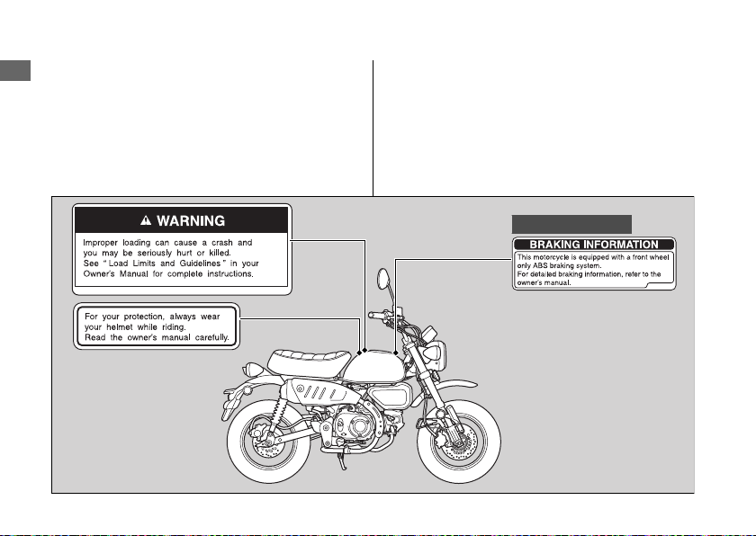
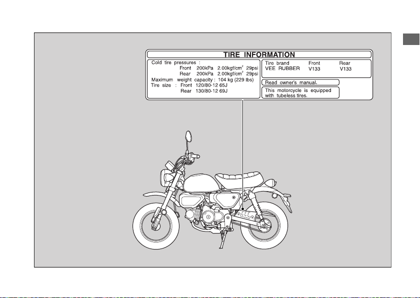
Safety and information labels on your vehicle
provide important safety information and may
warn you of potential hazards that could cause
serious injury. Read these labels carefully and
don't remove them.
6
If a label comes off or becomes hard to read,
contact your dealer for a replacement.
Monkey125A only
Page 11
Safety Labels
Vehicle Safety
7
Page 12
Safety Precautions
Safety Precautions
Vehicle Safety
● Ride cautiously and keep your hands on the
handlebar and feet on the footpegs.
● Always consider the safety of other drivers
and riders.
Protective Apparel
Make sure that you are wearing an approved
helmet, eye protection, and high-visibility
protective clothing. Ride defensively in response
to weather and road conditions.
Helmet
#
Should be safety-standard certified, highvisibility, and correct size for your head
● Must fit comfortably but securely, with the
chin strap fastened.
● Face shield with unobstructed field of vision
or other approved eye protection
Look for a DOT (Department of Transportation)
certification label on any helmet you buy.
8
3WARNING
Not wearing a helmet increases the
chance of serious injury or death in a
crash.
Make sure that you always wear an
approved helmet and protective
apparel.
Gloves
#
Full-finger leather gloves with high abrasion
resistance
Boots or Riding Shoes
#
Sturdy boots with non-slip soles and ankle
protection
Jacket and Pants
#
Protective, highly visible, long-sleeved jacket
and durable long pants for riding (or a
protective suit)
Page 13
Riding Precautions
Riding Precautions
Break-in Period
During the first 300 miles (500 km) of running,
follow these guidelines to ensure your vehicle's
future reliability and performance.
● Avoid full-throttle starts and rapid
acceleration.
● Avoid hard braking and rapid down-shifts.
● Ride conservatively.
Brakes
Observe the following guidelines:
● Avoid excessively hard braking and
downshifting.
u Sudden braking can reduce the vehicle's
stability.
u Where possible, reduce speed before
turning; otherwise you risk sliding out.
● Exercise caution on low traction surfaces.
u The tires slip more easily on such
surfaces and braking distances are
longer.
● Avoid continuous braking.
u Repeated braking, such as when
descending long, steep slopes can
seriously overheat the brakes, reducing
their effectiveness. Use engine braking
with intermittent use of the brakes to
reduce speed.
● For full braking effectiveness, operate both
the front and rear brakes together.
Continued
Vehicle Safety
9
Page 14

Riding Precautions
Anti-lock Brake System (ABS) on Front
#
Vehicle Safety
Wheel
Monkey125A only
This model equipped with an Anti-lock Brake
System (ABS) designed to help prevent the front
brake from locking up during hard braking.
● There is no ABS function to the rear wheel.
● ABS does not reduce braking distance. In
certain circumstances, ABS may result in a
longer stopping distance.
● ABS does not function at speeds below 6
mph (10 km/h).
● The brake lever may recoil slightly when
applying the brakes. This is normal.
● Always use the recommended front/rear
tires and sprockets to ensure correct ABS
operation.
10
Engine Braking
#
Engine braking helps slow your vehicle down
when you release the throttle. For further
slowing action, downshift to a lower gear. Use
engine braking with intermittent use of the
brakes to reduce speed when descending long,
steep slopes.
Wet or Rainy Conditions
#
Road surfaces are slippery when wet, and wet
brakes further reduce braking efficiency.
Exercise extra caution when braking in wet
conditions.
If the brakes get wet, apply the brakes while
riding at low speed to help them dry.
Page 15
Parking
● Park on a firm, level surface.
● If you must park on a slight incline or loose
surface, park so that the vehicle cannot
move or fall over.
● Make sure that high-temperature parts
cannot come into contact with flammable
materials.
● Do not touch the engine, muffler, brakes
and other high-temperature parts until they
cool down.
● To reduce the likelihood of theft, always lock
the handlebar and remove the key when
leaving the vehicle unattended.
Use of an anti-theft device is also
recommended.
Parking with the Side Stand
#
1.
Stop the engine.
2.
Push the side stand down.
3.
Slowly lean the vehicle to the left until its
weight rests on the side stand.
Riding Precautions
4.
Turn the handlebar fully to the left.
u Turning the handlebar to the right
reduces stability and may cause the
vehicle to fall.
5.
Turn the ignition switch to the LOCK
position and remove the key. 2 P. 24
Refueling and Fuel Guidelines
Follow these guidelines to protect the engine,
fuel system and catalytic converter:
● Use only unleaded gasoline.
● Use recommended octane number. Using
lower octane gasoline will result in
decreased engine performance.
● Do not use fuels containing a high
concentration of alcohol. 2 P. 111
● Do not use stale or contaminated gasoline
or an oil/gasoline mixture.
● Avoid getting dirt or water in the fuel tank.
Vehicle Safety
11
Page 16
Accessories & Modifications
Accessories &
Vehicle Safety
Modifications
We strongly advise that you do not add any
accessories that were not specifically designed
or approved for your vehicle by Honda or make
modifications to your vehicle from its original
design. Doing so can make it unsafe.
Modifying your vehicle may also void your
warranty and make your vehicle illegal to
operate on public roads. Before deciding to
install accessories on your vehicle be certain the
modification is safe and legal.
12
3WARNING
Improper accessories or modifications
can cause a crash in which you can be
seriously hurt or killed.
Follow all instructions in this owner's
manual regarding accessories and
modifications.
Do not pull a trailer with, or attach a sidecar to,
your vehicle. Your vehicle was not designed for
these attachments, and their use can seriously
impair your vehicle's handling.
Page 17
Loading
Loading
● Carrying extra weight affects your vehicle's
handling, braking and stability.
Always ride at a safe speed for the load you
are carrying.
● Avoid carrying an excessive load and keep
within specified load limits.
Maximum weight capacity 2 P. 117
● Tie all luggage securely, evenly balanced
and close to the center of the vehicle.
● Do not place objects near the lights or the
muffler.
3WARNING
Overloading, improper loading or
carrying a passenger can cause a crash
and you can be seriously hurt or killed.
Follow all load limits and other loading
guidelines in this manual.
Vehicle Safety
13
Page 18

Basic Operation Flow
Pre-ride Inspection
#
Operation Guide
14
Carefully inspect your vehicle to make
sure that it is safe to ride.
How to use basic features.
• Instruments
• Indicators
• Switches
• Steering Lock (P.24)
(P.
21)
(P.
(P.22)
18)
38)
(P.
Acceleration
#
Apply throttle gradually.
Obey the speed limit.
Starting the Engine
#
Start and warm the engine.
Avoid revving the engine.
Shift Change
#
(P.
27)
(P.
25)
Before pulling away, indicate
your direction with the turn
signal switch, and check for
oncoming traffic.
Starting the
#
Vehicle
Page 19
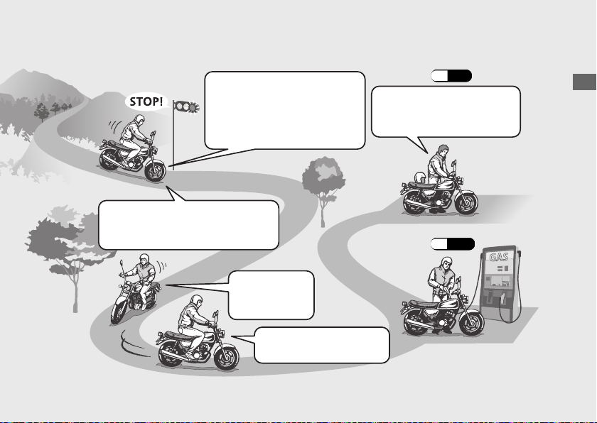
Braking
#
Stopping
#
If pulling off the road, signal early
enough to show traffic that you are
pulling over, and pull over smoothly.
Close the throttle and apply the
front and rear brakes together.
u
The brake light will indicate that
you have applied the brakes.
Turning Corners
#
Do your braking
before entering
corners.
Gradually reapply throttle
when exiting turn.
Parking
#
Park on a firm level surface.
Use the stand, and lock the
steering.
Refueling
#
(P.
(P.
11)
Operation Guide
28)
15
Page 20
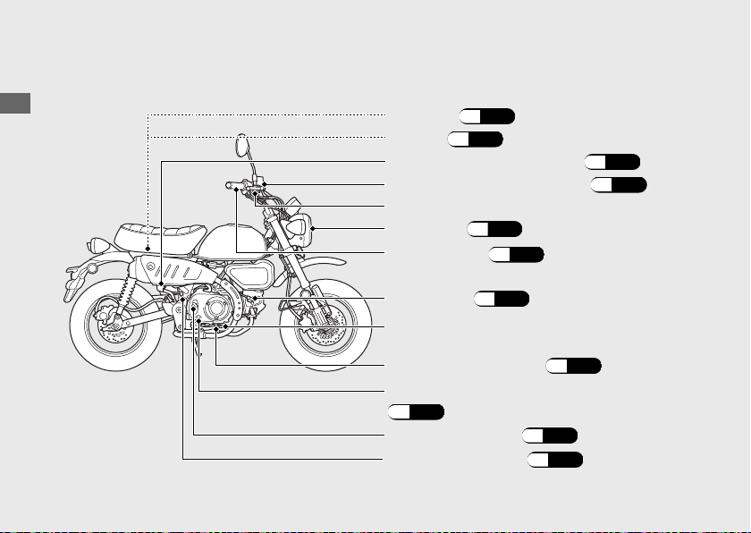
Parts Location
Operation Guide
16
Fuse box (P.
Battery
Rear brake fluid reservoir
(P.
53)
93)
(P.
64)
Front brake fluid reservoir (P.64)
Front brake lever
Headlight
Throttle grip
Spark plug
(P.
(P.
77)
(P.
57)
75)
Rear brake pedal
Engine oil drain bolt
(P.
60)
Engine oil level inspection window
(P.
59)
Engine oil fill cap
Brake light switch
(P.
59)
(P.66)
Page 21
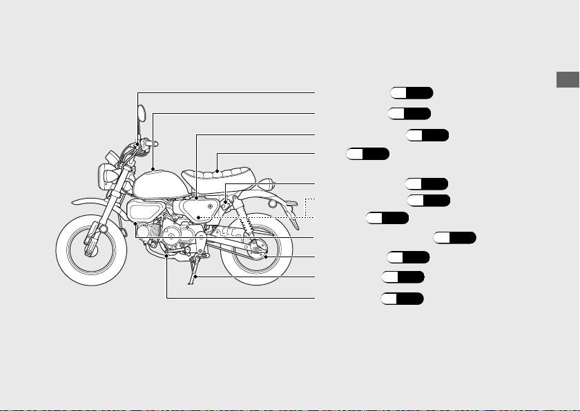
Clutch lever
Fuel fill cap
(P.
(P.
Left side cover
(P.
Seat
55)
72)
28)
(P.56)
Operation Guide
(P.
29)
(P.
(P.
30)
29)
Helmet holder
Document bag
Tool kit
Crankcase breather (P.
Drive chain
Side stand
Shift lever (P.
(P.
68)
(P.67)
27)
76)
17
Page 22
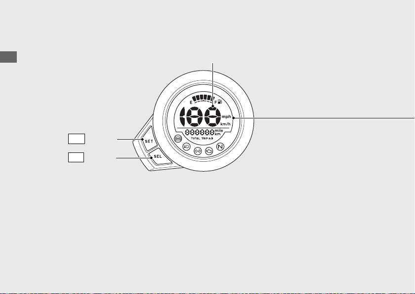
Instruments
Operation Guide
Display Check
When the ignition switch is turned to the ON position, all the mode and digital
segments will show.
If any part of these displays does not come on when it should, have your dealer check
for problems.
18
SET
SEL
Speedometer
button
button
Page 23
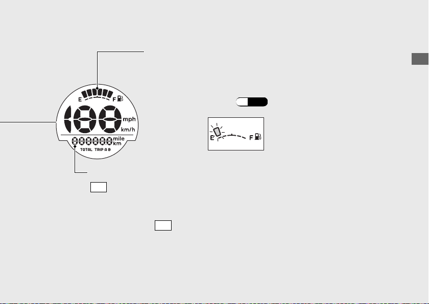
Fuel gauge
Remaining fuel when only 1st (E) segment starts flashing:
approximately 0.476 US gal (1.80 L)
If the fuel gauge indicator flashes in a repeat
(P.
:
pattern or turns off
82)
Odometer [TOTAL] & Tripmeter [TRIP A/B]
SEL
button switches between the odometer and tripmeters.
● Odometer: Total distance ridden.
● Tripmeter: Distance ridden since tripmeter was reset (press
and hold the
SET
button to reset to 0.0 km/mile).
Operation Guide
Continued
19
Page 24
Instruments (Continued)
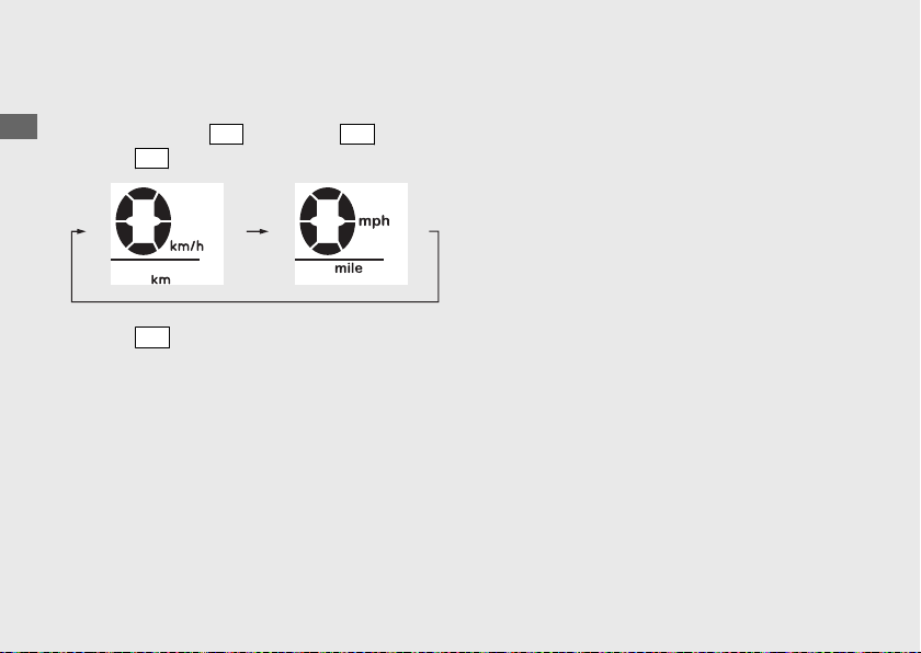
Changing of speed and mileage unit
a
Turn the ignition switch to the ON position.
b
Operation Guide
Press and hold
c
Press
SEL
SEL
button and
button to select either “km/h” and “km” or “mph” and “mile”.
SET
button.
Press
SET
button.
d
The speed and mileage unit is set, and then the display returns to the ordinary display.
u The speed and mileage unit can also be set by turning the ignition switch to the OFF position.
20
Page 25
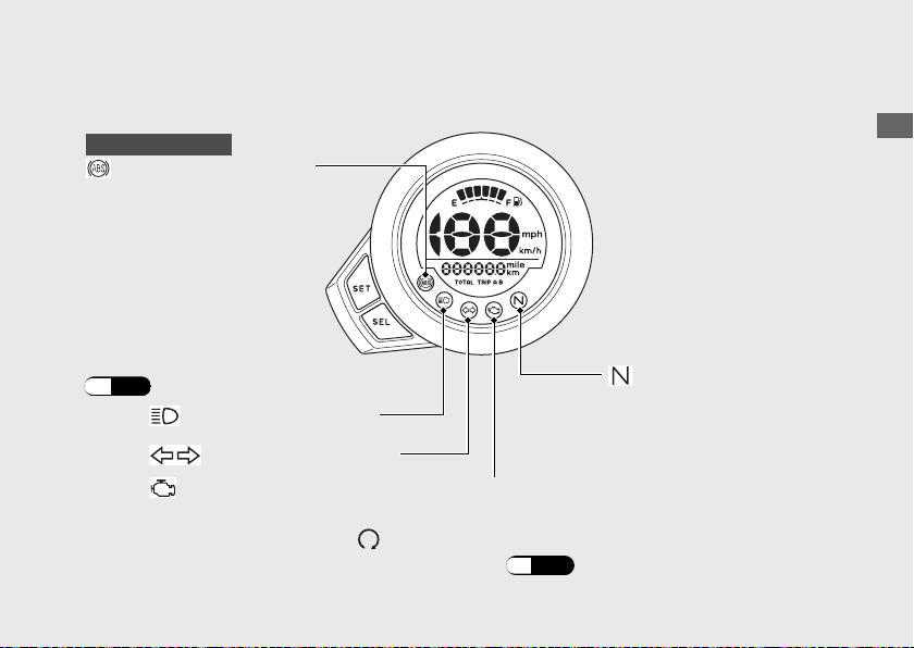
Indicators
If one of these indicators does not come on when it should, have your dealer
check for problems.
Monkey125A only
ABS (Anti-lock Brake
System) indicator
Comes on when the ignition
switch is turned to the ON
position.
Goes off when your speed
reaches approximately 6
mph (10 km/h)
If it comes on while riding:
(P.81)
.
Neutral indicator
High beam indicator
Turn signal indicator
PGM-FI (Programmed Fuel Injection) malfunction indicator lamp (MIL)
Comes on briefly when the ignition switch is turned to the ON position with the
engine stop switch in the
If it comes on while engine is running:
(Run) position.
(P.
Comes on when the
transmission is in Neutral.
80)
Operation Guide
21
Page 26
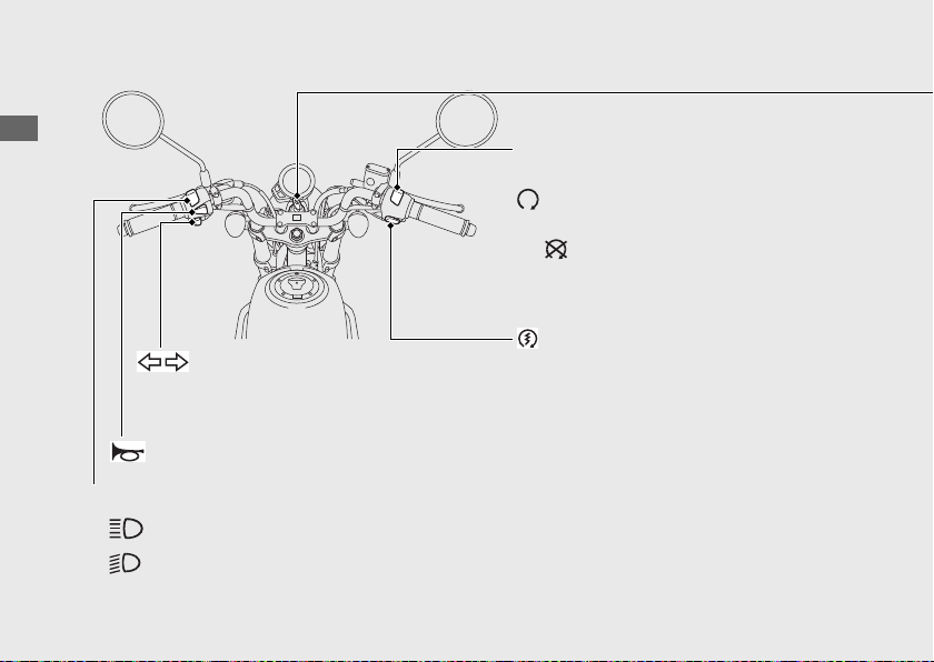
Switches
Operation Guide
u Pressing the switch turns the
turn signal off.
Horn button
Headlight dimmer switch
• : High beam
• : Low beam
22
Engine stop switch
Should normally remain in the
(Run) position.
u In an emergency, switch to the
(Stop) position (the starter
motor will not operate) to stop
the engine.
Start button
Turn signal switch
Page 27
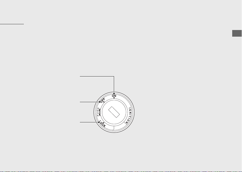
Ignition switch
Switches the electrical system on/off, locks the
steering.
u Key can be removed when in the OFF or
LOCK position.
ON
Turns electrical system
on for starting/riding.
OFF
Turns engine off.
LOCK
Locks steering.
Operation Guide
Continued
23
Page 28
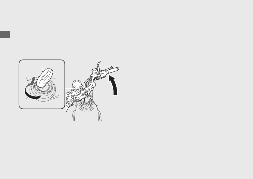
Switches (Continued)
Steering Lock
Lock the steering when parking to help
Operation Guide
prevent theft.
A U-shaped wheel lock or similar device is
also recommended.
Ignition key
Push
b
Turn
24
a
Locking
#
a
Turn the handlebar all the way to the left.
b
Push the key down, and turn the ignition
switch to the LOCK position.
u Jiggle the handlebar if the lock is difficult
to engage.
c
Remove the key.
Unlocking
#
Insert the key, push it in, and turn the ignition
switch to the OFF position.
Page 29
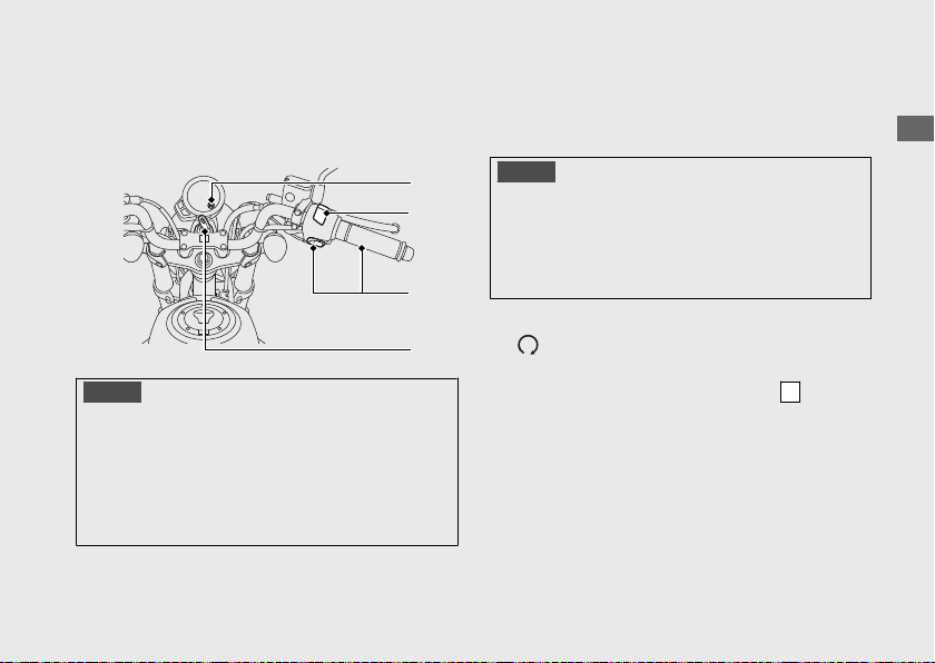
Starting the Engine
Start your engine using the following
procedure, regardless of whether the engine
is cold or warm.
c
a
d
b
NOTICE
• If the engine does not start within 5 seconds,
turn the ignition switch to the OFF
and wait 10 seconds before trying to start
the engine again to recover battery voltage.
Extended fast idling and revving the engine can
•
damage the engine, and the exhaust system.
position
Consult your dealer for advice if you plan to
ride your vehicle at an altitude above 8,000
feet (2,500 m).
NOTICE
If the vehicle is transported to a place 6,500 feet
(2,000 m) higher or lower than the start point,
you may not be able to achieve sufficient engine
performance at the new altitude. Consult your
dealer before transporting your vehicle.
a
Make sure the engine stop switch is in the
(Run) position.
b
Turn the ignition switch to the ON position.
c
Shift the transmission to Neutral (
indicator to come on). Alternatively, pull in
the clutch lever to start your vehicle with the
transmission in gear so long as the side
stand is raised.
N
Operation Guide
Continued
25
Page 30
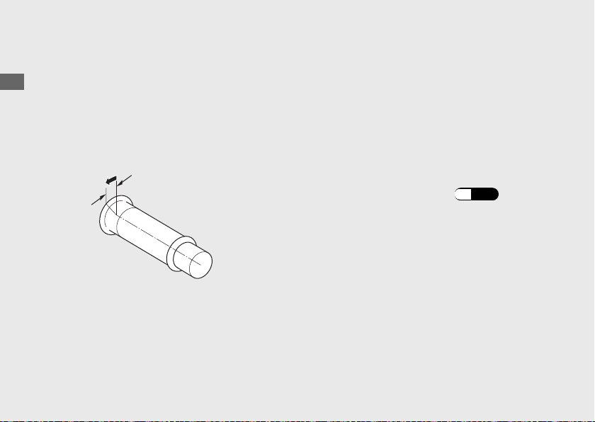
Starting the Engine (Continued)
d
Press the start button with the throttle
completely closed.
Operation Guide
u If you cannot start the engine, open the
throttle slightly (about
without freeplay) and press the start
button.
About 0.1 in (3 mm), without
freeplay
26
0.1 in (3 mm),
If the engine does not start:
a
Open the throttle fully and press the start
button for 5 seconds.
b
Repeat the normal starting procedure.
c
If the engine starts, open the throttle slightly
if idling is unstable.
d
If the engine does not start, wait 10 seconds
before trying step a & b again.
If Engine Will Not Start
#
(P.
79)
Page 31
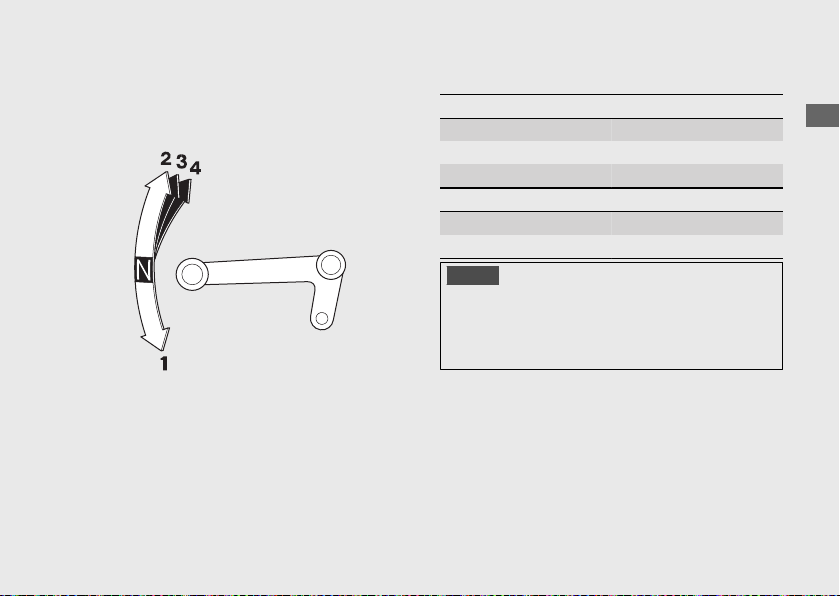
Shifting Gears
Your vehicle transmission has 4 forward
gears in a one-down,
If you put the vehicle in gear with the side
stand down, the engine will shut off.
three-up shift pattern.
Recommended Shift Points
#
Shifting Up
From 1st to 2nd 12 mph (20 km/h)
From 2nd to 3rd 19 mph (30 km/h)
From 3rd to 4th 25 mph (40 km/h)
Shifting Down
From 4th to 3rd 16 mph (25 km/h)
From 3rd to 2nd 12 mph (19 km/h)
NOTICE
Improper shifting can damage the engine,
transmission, and drive train. Also, coasting or
towing the vehicle for long distances with the
engine off can damage the transmission.
Operation Guide
27
Page 32
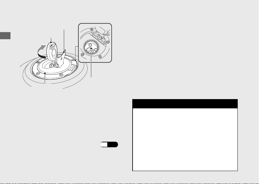
Refueling
Lock cover
Ignition key
Operation Guide
Fuel fill cap
Do not fill with fuel above the level plate.
Fuel type: Unleaded gasoline only
Recommended fuel octane number:
Pump Octane Number (PON) 86
Tank capacity: 1.48 US gal (5.6 L)
Level plate
or higher.
Opening the Fuel Fill Cap
Open the lock cover, insert the ignition key,
and turn it clockwise to open the fuel fill cap.
Closing the Fuel Fill Cap
a
After refueling, push the fuel fill cap until it
locks.
b
Remove the ignition key and close the lock
cover.
u The ignition key cannot be removed if
the fuel fill cap is not locked.
3WARNING
Gasoline is highly flammable and
explosive. You can be burned or
seriously injured when handling fuel.
Refueling and Fuel Guidelines
#
28
(P.11)
• Stop the engine, and keep heat,
sparks, and flame away.
• Handle fuel only outdoors.
• Wipe up spills immediately.
Page 33
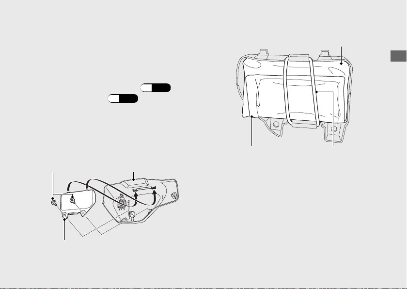
Storage Equipment
Document Bag/Tool Kit
Document bag and tool kit are stored on the
inner left side cover by the rubber strap.
Removing the inner left side cover
#
a
Remove the left side cover.
b
Remove the clips.
c
Remove the inner left side cover.
Installing the inner left side cover
#
Install the parts in the reverse order of
removal.
Clips
Inner left side cover
(P.
Left side cover
54)
(P.
56)
Tool kit
Operation Guide
Document bag Rubber strap
Continued
29
Page 34
Storage Equipment (Continued)
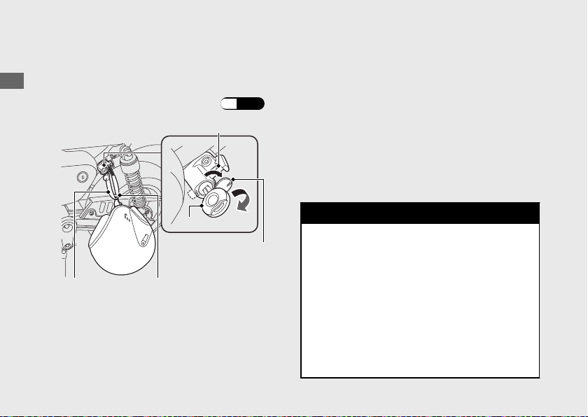
Helmet holder
The helmet holder is on the left side below
the seat.
Operation Guide
A helmet set wire is in the tool kit. (P.29)
Holder pin
Unlocking
#
Open the lock cover, insert the ignition key
and turn it clockwise.
Locking
#
a
Hang both ends of the helmet set wire that
has been passed through the helmet D-ring
on the holder pin and push it in to lock.
b
Remove the key and close the lock cover.
u Use the helmet holder only when parked.
30
Ignition key
Helmet D-ringHelmet set wire
Lock cover
3WARNING
Riding with a helmet attached to the
holder can interfere with the rear wheel
or suspension and could cause a crash
in which you can be seriously hurt or
killed.
Use the helmet holder only while
parked. Do not ride with a helmet
secured by the holder.
Page 35

Maintenance
Please read “Importance of Maintenance” and “Maintenance Fundamentals” carefully
before attempting any maintenance. Refer to “Specifications” for service data.
Importance of Maintenance ........................... P. 32
Maintenance Schedule
Maintenance Record......................................... P. 37
Maintenance Fundamentals ...........................P. 38
Tool....................................................................... P. 52
Removing & Installing Body Components..P. 53
Battery.................................................................... P. 53
Clip.......................................................................... P. 54
Seat ......................................................................... P. 55
Left Side Cover..................................................... P. 56
Spark Plug ........................................................... P. 57
Engine Oil ............................................................ P. 59
Air Cleaner........................................................... P. 62
Brakes................................................................... P. 64
..................................... P. 34
Side Stand ...........................................................P. 67
Drive Chain.......................................................... P. 68
Clutch ...................................................................P. 72
Throttle ................................................................P. 75
Crankcase Breather ........................................... P. 76
Other Adjustments............................................ P. 77
Adjusting the Headlight Aim ............................ P. 77
Page 36
Importance of Maintenance
Importance of Maintenance
Keeping your vehicle well-maintained is
absolutely essential to your safety and to
protect your investment, obtain maximum
Maintenance
performance, avoid breakdowns, and reduce air
pollution. Maintenance is the owner's
responsibility. Be sure to inspect your vehicle
before each ride, and perform the periodic
checks specified in the Maintenance Schedule.
2 P. 34
3WARNING
Improperly maintaining your vehicle or
failing to correct a problem before you
ride can cause a crash in which you can
be seriously hurt or killed.
Always follow the inspection and
maintenance recommendations and
schedules in this owner's manual.
32
For information about the exhaust emission and
noise emission requirements of the U.S.
Environmental Protection Agency (EPA), and the
California Air Resources Board (CARB). 2 P. 106
Maintenance, replacement or repair of the
emission control devices and systems may
be performed by any vehicle repair
establishment or individual using parts
that are “certified” to EPA standards.
Page 37
Maintenance Safety
Always read the maintenance instructions
before you begin each task, and make sure that
you have the tools, parts, and skills required.
We cannot warn you of every conceivable
hazard that can arise in performing
maintenance. Only you can decide whether or
not you should perform a given task.
Follow these guidelines when performing
maintenance.
● Stop the engine and remove the key.
● Place your vehicle on a firm, level surface
using the side stand or a maintenance stand
to provide support.
● Allow the engine, muffler, brakes, and other
high-temperature parts to cool before
servicing as you can get burned.
● Run the engine only when instructed, and
do so in a well-ventilated area.
Importance of Maintenance
Maintenance
33
Page 38
Maintenance Schedule
The maintenance schedule specifies the
maintenance requirements necessary to ensure
safe, dependable performance, and proper
emission control.
Maintenance
Maintenance work should be performed in
accordance with Honda's standards and
specifications by properly trained and equipped
technicians. Your dealer meets all of these
requirements. All scheduled maintenance is
considered a normal owner operating cost and
will be charged to you by your dealer. Keeping
an accurate maintenance record will help
ensure your vehicle is properly maintained.
2 P. 37
34
Make sure whoever performs the scheduled
maintenance completes the maintenance
record. Retain all service documents. If you sell
your vehicle, these service documents should
be transferred with the vehicle to the new
owner.
Page 39
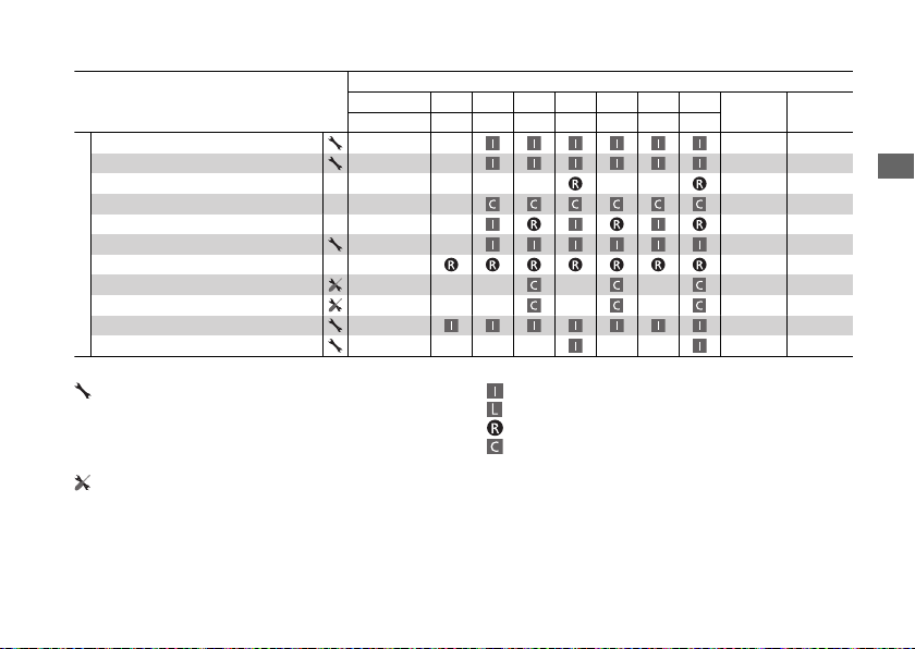
Maintenance Schedule
*1
Items
Fuel Line
Throttle Operation 75
Air Cleaner
Crankcase Breather
Spark Plug 57
Valve Clearance –
Engine Oil 1 Year 60
Engine Oil Strainer Screen –
Engine Oil Centrifugal Filter –
Emission-Related Items
Engine Idle Speed –
Evaporative Emission Control System
*2
*3
× 1,000 mi 0.6 4 8 12 16 20 24
× 1,000 km 1.0 6.4 12.8 19.2 25.6 32.0 38.4
*4
Maintenance Level Maintenance Legend
: Intermediate. We recommend service by your
dealer, unless you have the necessary tools and are
mechanically skilled.
Procedures are provided in an official Honda Service
Manual (2 P. 112
).
: Technical. In the interest of safety, have your vehicle
serviced by your dealer.
Frequency
Regular
Replace
Inspect (clean, adjust, lubricate, or replace, if necessary)
:
Lubricate
:
Replace
:
Clean
:
Refer to
page
–
51, 62
76
–
Maintenance
Continued
35
Page 40
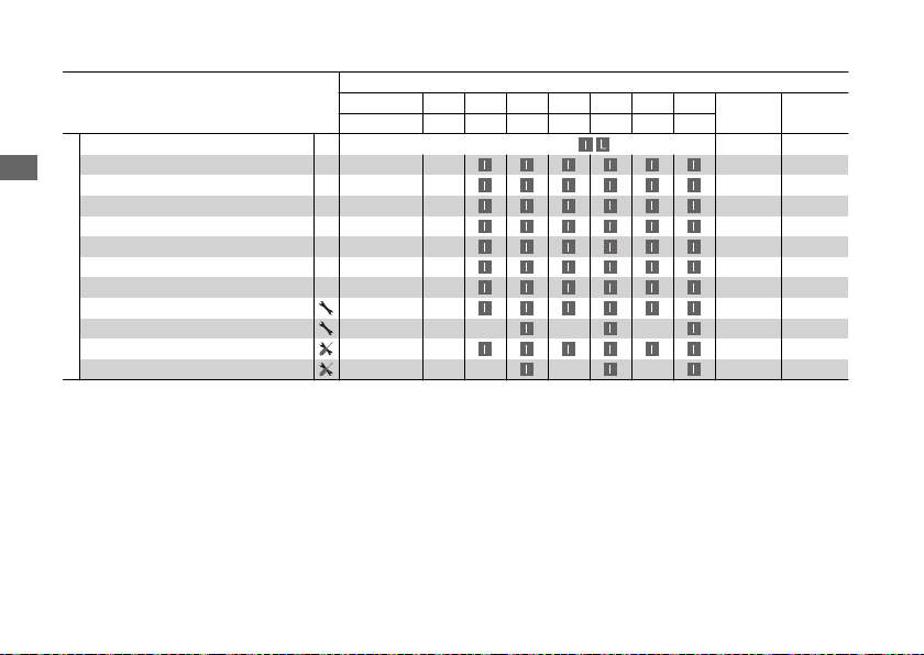
Maintenance Schedule
*1
Items
Drive Chain
Brake Fluid
Maintenance
Brake Pads Wear 65
Brake System 64
Brake Light Switch 66
Headlight Aim 77
Clutch System 72
Side Stand 67
Suspension –
Nuts, Bolts, Fasteners –
Non-Emission-Related Items
Wheels/Tires –
Steering Head Bearings –
Notes:
*
1 : At higher odometer reading, repeat at the frequency interval established here.
*
2 : Service more frequently when riding in unusually wet or dusty areas.
*
3 : Service more frequently when riding in rain or at full throttle.
*
4 : 50 STATE (meets california)
*
5: Replacement requires mechanical skill.
*5
× 1,000 mi 0.6 4 8 12 16 20 24
× 1,000 km 1.0 6.4 12.8 19.2 25.6 32.0 38.4
Every 300 mi (500 km):
Frequency
36
Regular
Replace
2 Years 64
Refer to
page
68
Page 41
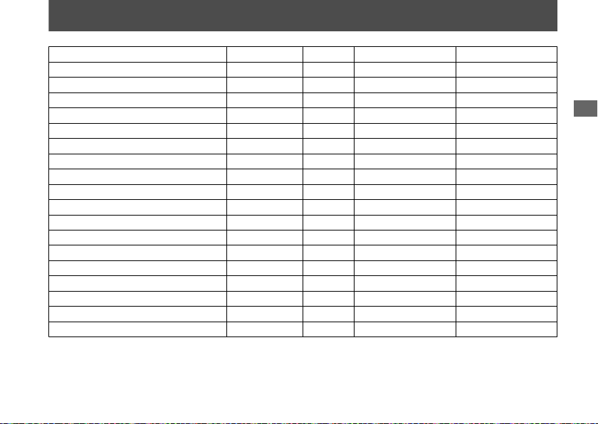
Maintenance Record
Distance Odometer Date Performed By: Notes
600 miles (1,000 km)
4,000 miles (6,400 km)
8,000 miles (12,800 km)
12,000 miles (19,200 km)
16,000 miles (25,600 km)
20,000 miles (32,000 km)
24,000 miles (38,400 km)
28,000 miles (44,800 km)
32,000 miles (51,200 km)
36,000 miles (57,600 km)
40,000 miles (64,000 km)
44,000 miles (70,400 km)
48,000 miles (76,800 km)
52,000 miles (83,200 km)
56,000 miles (89,600 km)
60,000 miles (96,000 km)
64,000 miles (102,400 km)
68,000 miles (108,800 km)
Maintenance
37
Page 42
Maintenance Fundamentals
Pre-ride Inspection
To ensure safety, it is your responsibility to
perform a pre-ride inspection and make sure
that any problem you find is corrected. A pre-
Maintenance
ride inspection is a must, not only for safety, but
because having a breakdown, or even a flat tire,
can be a major inconvenience.
Check the following items before you get on
your vehicle:
● Tire tread wear and air pressures are within
limits. 2 P. 47
● Lights, horn, and turn signals operate
normally.
● Check the condition of the drive chain.
Adjust slack and lubricate as needed. 2 P. 45
Check the following items if you are carrying a
cargo:
● Combined weight is within load limits.
2 P. 117
● Cargo is secured properly.
38
Check the following items after you get on your
vehicle:
● Throttle action moves smoothly without
binding. 2 P. 75
● Brake lever and pedal operate normally.
● Check the fuel level and refuel when
needed. 2 P. 11, 2 P. 28
● Engine stop switch functions properly.
2 P. 22
Check the following items at regular intervals:
● Oil level is between the upper and lower
level marks. 2 P. 59
● Brake fluid level is
Front: above the LOWER level mark. 2 P. 64
Rear: between the UPPER and LOWER level
marks. 2 P. 64
● Side stand functions properly. 2 P. 67
Page 43
Periodic Checks
You should also perform other periodic
maintenance checks at least once a month
regardless of how often you ride, or more often
if you ride frequently.
Also, check the odometer reading against the
Maintenance Schedule and perform all
maintenance that is due. 2 P. 34
Maintenance Fundamentals
Maintenance
Tires and wheels
Check the air pressure (2 P. 47
(2 P. 47), and check the wheels for damage.
), examine tread for wear and damage
Fluid levels Check the engine oil level (2 P. 59), and brake fluid level (2 P. 64).
Lights
Controls
Drive chain
Check that the headlight, position light, brake light, taillight, turn
signals and license plate light are working properly.
Check the freeplay of the clutch lever (2 P. 72), and throttle grip
(2 P. 75).
Check the slack (2 P. 68), adjust the slack (2 P. 69), and lubricate
(2 P. 46) as needed.
Fuses Check that you have a full supply of spare fuses.
Nuts & bolts Check the major nuts and bolts, and tighten as needed.
39
Page 44
Maintenance Fundamentals
Replacing Parts
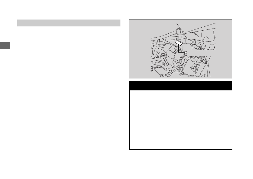
Always use Honda Genuine Parts or their
equivalents to ensure reliability and safety.
When ordering colored components, specify
Maintenance
the model name, color, and code mentioned on
the color label.
The color label is attached to the frame.
To check the color label, remove the left side
cover. 2 P. 56
40
Color label
3WARNING
Installing non-Honda parts may make
your vehicle unsafe and cause a crash in
which you can be seriously hurt or
killed.
Always use Honda Genuine Parts or
equivalents that have been designed
and approved for your vehicle.
Page 45
Maintenance Fundamentals
Battery
Your vehicle has a maintenance-free type
battery. You do not have to check the battery
electrolyte level or add distilled water. Clean the
battery terminals if they become dirty or
corroded.
Do not remove the battery cap seals. There is
no need to remove the cap when charging.
NOTICE
An improperly disposed of battery can be
harmful to the environment and human health.
Always confirm local regulations for proper
battery disposal instruction.
What to do in an emergency
#
If any of the following occur, immediately see
your doctor.
● Electrolyte splashes into your eyes:
u Wash your eyes repeatedly with cool
water for at least 15 minutes. Using water
under pressure can damage your eyes.
● Electrolyte splashes onto your skin:
u Remove affected clothing and wash your
skin thoroughly using water.
● Electrolyte splashes into your mouth:
u Rinse mouth thoroughly with water, and
do not swallow.
3WARNING
The battery gives off explosive
hydrogen gas during normal operation.
A spark or flame can cause the battery
to explode with enough force to kill or
seriously hurt you.
Wear protective clothing and a face
shield, or have a skilled mechanic do
the battery servicing.
WARNING: Battery posts, terminals, and
related accessories contain lead and lead
compounds.
Continued
Maintenance
41
Page 46
Maintenance Fundamentals
Wash your hands after handling.
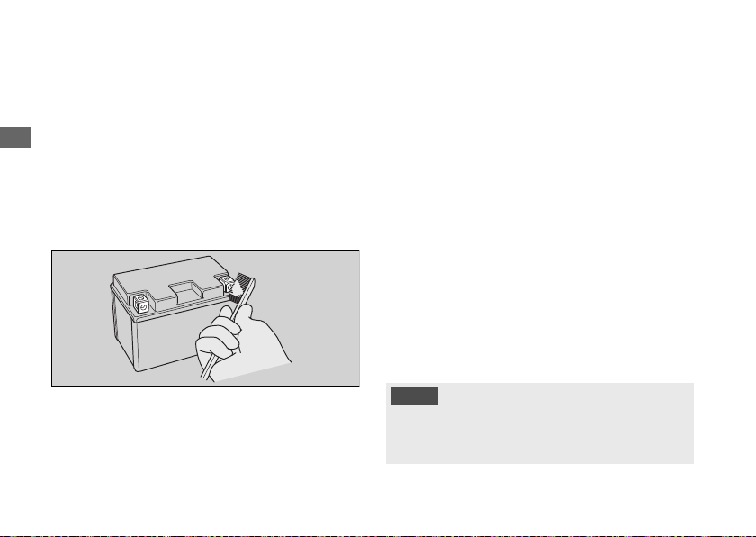
Cleaning the Battery Terminals
#
1.
Remove the battery. 2 P. 53
2.
Maintenance
If the terminals are starting to corrode and
are coated with a white substance, wash
with warm water and wipe clean.
3.
If the terminals are heavily corroded, clean
and polish the terminals with a wire brush or
sandpaper. Wear safety glasses.
4.
After cleaning, reinstall the battery.
The battery has a limited life span. Consult your
dealer about when you should replace the
42
battery. Always replace the battery with another
maintenance-free battery of the same type.
Charging
#
If you use electrical accessories that drain the
battery or you do not ride frequently, we
recommend that you charge the battery every
30 days using a charger designed specifically for
your Honda, which can be purchased from your
dealer. Read the information that came with
your battery charger and follow the instructions
on the battery. Avoid using an automobile-type
battery charger, as these can overheat a
motorcycle battery and cause permanent
damage.
Make sure the ignition switch is in the OFF
position before charging the battery.
NOTICE
Improper charging can damage the battery. If
you can’t charge the battery or it appears unable
to hold a charge, contact your dealer.
Page 47
NOTICE
Jump starting using an automobile battery can
damage your vehicle's electrical system and is
not recommended. Bump starting is also not
recommended.
NOTICE
Installing non-Honda electrical accessories can
overload the electrical system, discharging the
battery and possibly damaging the system.
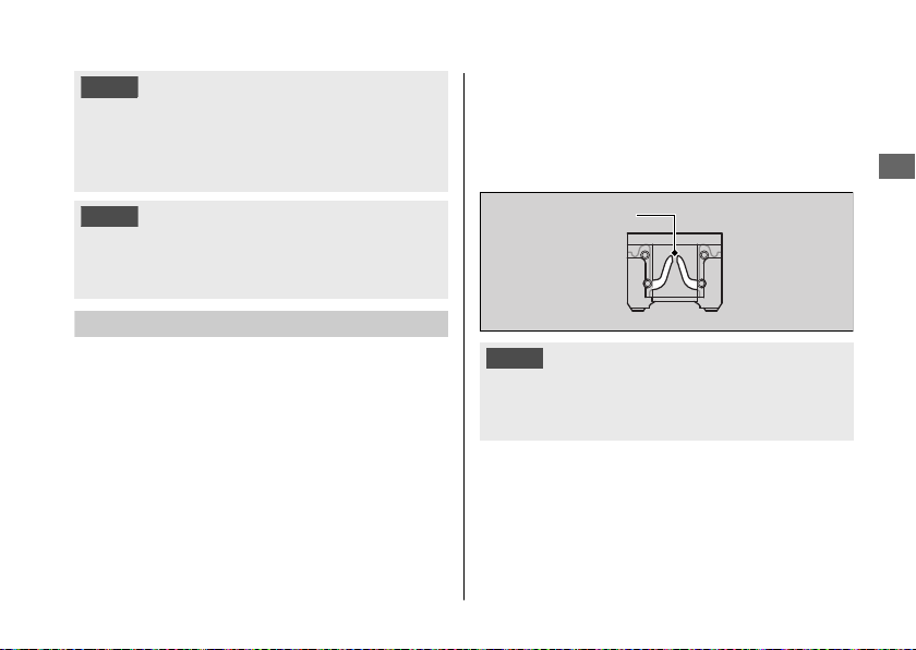
Fuses
Fuses protect the electrical circuits on your
vehicle. If something electrical on your vehicle
stops working, check for and replace any blown
fuses. 2 P. 93
Maintenance Fundamentals
Inspecting and Replacing Fuses
#
Turn the ignition switch to the OFF position to
remove and inspect fuses. If a fuse is blown,
replace with a fuse of the same rating. For fuse
ratings, see “Specifications.” 2 P. 119
Blown fuse
NOTICE
Replacing a fuse with one that has a higher
rating greatly increases the chance of damage to
the electrical system.
If a fuse fails repeatedly, you likely have an
electrical fault. Have your vehicle inspected by
your dealer.
Maintenance
43
Page 48
Maintenance Fundamentals
Engine Oil
Engine oil consumption varies and oil quality
deteriorates according to riding conditions and
time elapsed.
Maintenance
Check the engine oil level regularly, and add the
recommended engine oil if necessary. Dirty oil
or old oil should be changed as soon as
possible.
Selecting the Engine Oil
#
For recommended engine oil, see
“Specifications.” 2 P. 118
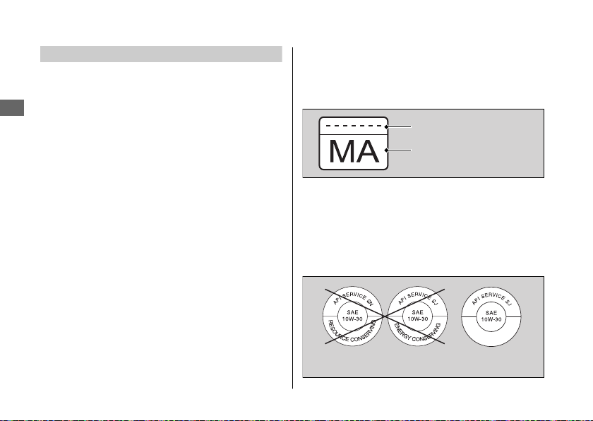
If you use non-Honda engine oil, check the
label to make sure that the oil satisfies all of the
following standards:
● JASO T 903 standard
● SAE standard
● API classification
44
*2
: 10W-30
*3
: SG or higher
*1
: MA
*1.
The JASO T 903 standard is an index for engine
oils for 4-stroke motorcycle engines. There are
two classes: MA and MB. For example, the
following label shows the MA classification.
Oil code
Oil classification
*2.
The SAE standard grades oils by their viscosity.
*3.
The API classification specifies the quality and
performance rating of engine oils. Use SG or
higher oils, excluding oils marked as “Energy
Conserving” or “Resource Conserving” on the
circular API service symbol.
Not recommended Recommended
Page 49
Maintenance Fundamentals
Brake Fluid
Do not add or replace brake fluid, except in an
emergency. Use only fresh brake fluid from a
sealed container. If you do add fluid, have the
brake system serviced by your dealer as soon as
possible.
NOTICE
Brake fluid can damage plastic and painted
surfaces.
Wipe up spills immediately and wash thoroughly.
Recommended brake fluid:
Honda DOT 3 or DOT 4 Brake Fluid
or
equivalent
Drive Chain
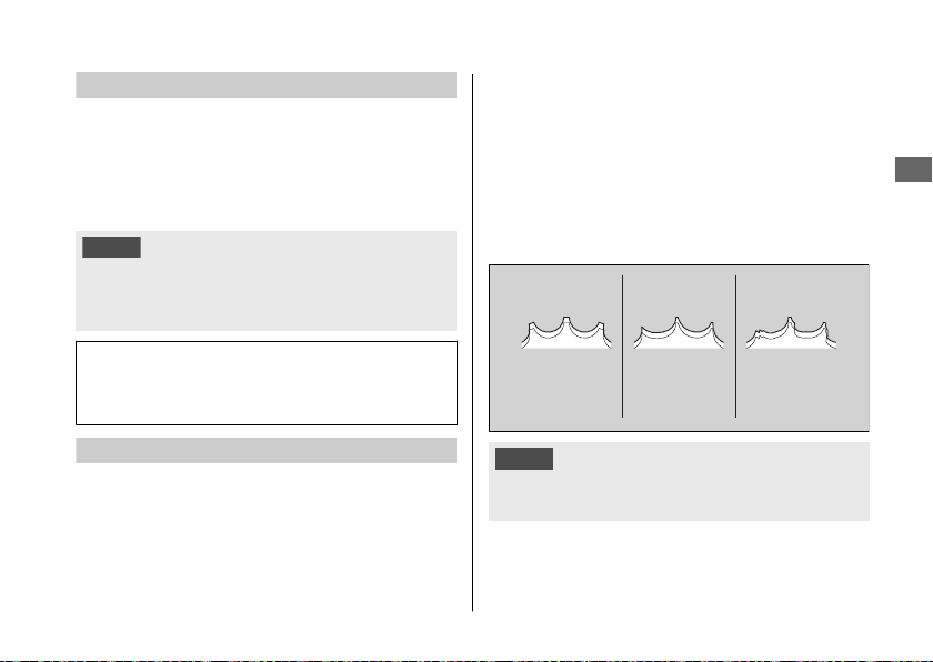
The drive chain must be inspected and
lubricated regularly. Inspect the chain more
frequently if you often ride on bad roads, ride at
high speed, or ride with repeated fast
acceleration. 2 P. 68
If the chain does not move smoothly, makes
strange noises, has damaged rollers, has loose
pins, or kinks, have the chain inspected by your
dealer.
Also inspect the drive sprocket and driven
sprocket. If either has worn or damaged teeth,
have the sprocket replaced by your dealer.
Normal
(GOOD)
NOTICE
Use of a new chain with worn sprockets will cause
rapid chain wear.
Worn
(REPLACE)
Damaged
(REPLACE)
Continued
Maintenance
45
Page 50
Maintenance Fundamentals
Cleaning and Lubricating
#
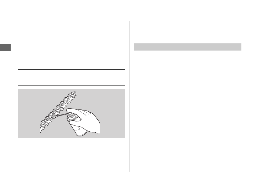
After inspecting the slack, clean the chain and
sprockets while rotating the rear wheel. Use a
dry cloth with high flash-point solvent. Use a
soft brush if the chain is dirty.
Maintenance
After cleaning, wipe dry and lubricate with the
recommended lubricant.
Recommended lubricant:
Pro Honda HP Chain Lube or equivalent
Never use gasoline or low flash point solvents
for cleaning the drive chain.
A fire or explosion could result.
46
Avoid getting lubricant on the brakes or tires.
Avoid applying excess chain lubricant to prevent
spray onto your clothes and the vehicle.
Crankcase Breather
Service more frequently when riding in rain, at
full throttle, or after the vehicle is washed or
overturned. Service if the deposit level can be
seen in the transparent section of the drain
tube.
If the drain tube overflows, the air filter may
become contaminated with engine oil causing
poor engine performance. 2 P. 76
Page 51
Maintenance Fundamentals
Tires (Inspecting/Replacing)
Checking the Air Pressure
#
Visually inspect your tires and use an air
pressure gauge to measure the air pressure at
least once a month or any time you think the
tires look low. Always check air pressure when
your tires are cold.
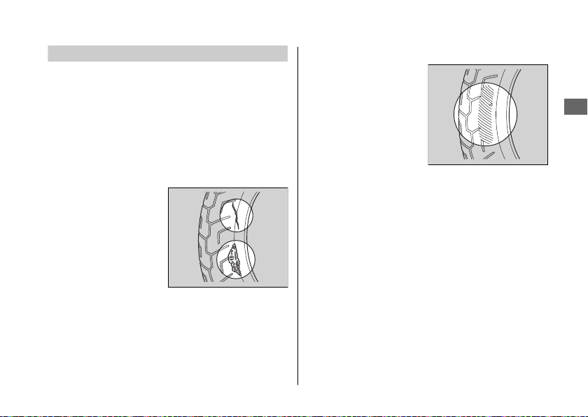
Inspecting for Damage
#
Inspect the tires for
cuts, slits, or cracks that
exposes fabric or
cords, or nails or other
foreign objects
embedded in the side
of the tire or the tread.
Also inspect for any unusual bumps or bulges in
the side walls of the tires.
Inspecting for Abnormal Wear
#
Inspect the tires for
signs of abnormal wear
on the contact surface.
Continued
Maintenance
47
Page 52
Maintenance Fundamentals
Inspecting Tread Depth
#
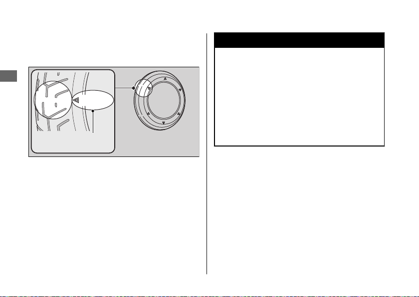
Inspect the tread wear indicators. If they
become visible, replace the tires immediately.
Maintenance
or TWI
Wear indicator
location mark
48
3WARNING
Riding on tires that are excessively worn
or improperly inflated can cause a crash
in which you can be seriously hurt or
killed.
Follow all instructions in this owner's
manual regarding tire inflation and
maintenance.
Page 53
Maintenance Fundamentals
Have your tires replaced by your dealer.
For recommended tires and air pressure, see
“Specifications.” 2 P. 118
Follow these guidelines whenever you replace
tires.
● Use the recommended tires or equivalents
of the same size, construction, speed rating,
and load range.
● Do not install a tube inside a tubeless tire on
this vehicle. Excessive heat build-up can
cause the tube to burst.
● Use only tubeless tires on this vehicle.
The rims are designed for tubeless tires, and
during hard acceleration or braking, a tubetype tire could slip on the rim and cause the
tire to rapidly deflate.
3WARNING
Installing improper tires on your vehicle
can adversely affect handling and
stability, and can cause a crash in which
you can be seriously hurt or killed.
Always use the size and type of tires
recommended in this owner's manual.
Maintenance
49
Page 54
Maintenance Fundamentals
Tire Service Life
The service life of your tires is dependent on
many factors, including, but not limited to,
riding habits, road conditions, vehicle loading,
Maintenance
tire air pressure, maintenance history, speed,
and environmental conditions (even when the
tires are not in use).
In addition to your regular inspections and
maintenance, it is recommended that you have
annual inspections performed once the tires
reach 5 years old. It is also recommended that
all tires be removed from service after 10 years
from the date of manufacture, regardless of
their condition or state of wear.
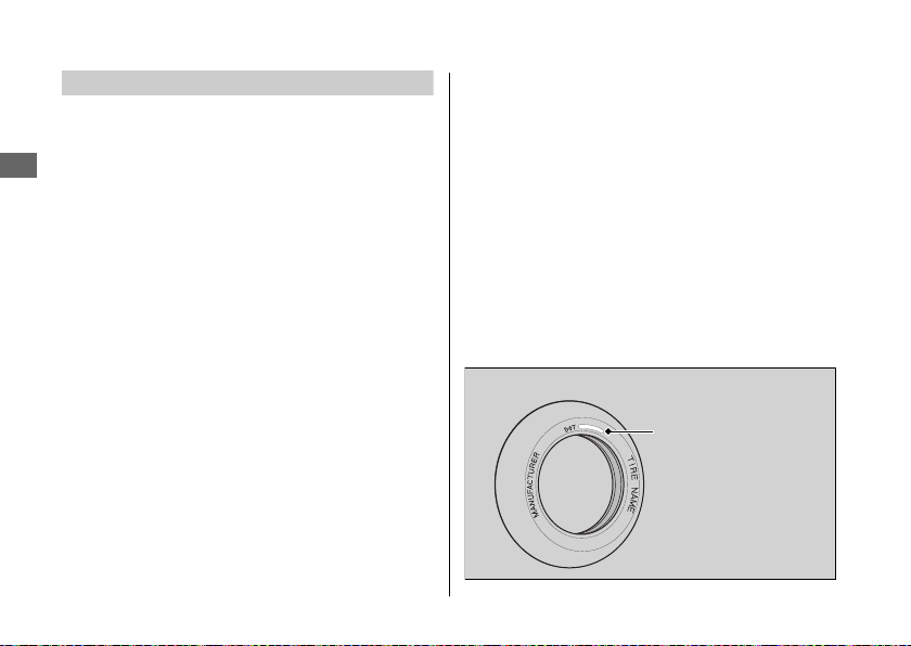
The last four digits of the TIN (tire identification
number) indicate the date of manufacture.
50
Tire Identification Number (TIN)
#
The tire identification number (TIN) is a group
of numbers and letters located on the sidewall
of the tire.
a b c
DOT XXXX XXXX 22 09
DOT: This indicates that the tire meets all
requirements of the U.S. Department
of Transportation.
a XXXX:
b XXXX:
c 22 09: Date of manufacture (week & year).
Factory code
Tire type code
Example: week 22 in year 09.
Tire Labeling Example
Tire identification
number (TIN)
Page 55
Air Cleaner
This vehicle is equipped with a viscous type air
cleaner element which cannot be cleaned with
compressed air or otherwise without degrading
its performance.
If the filter becomes dirty, replace it with a new
one.
Maintenance Fundamentals
Maintenance
51
Page 56
Tool
The tool kit is located behind the right side
cover. 2 P. 29
You can perform some roadside repairs, minor
adjustments and parts replacement with the
Maintenance
provided tools.
● Fuse puller
● Standard/Phillips screwdriver
● Screwdriver handle
● 6 mm Hex wrench
● Helmet set wire
52
Page 57
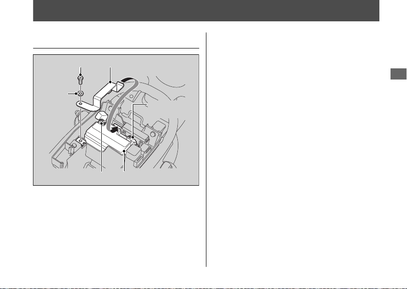
Removing & Installing Body Components
3.
Battery
Battery holder
Bolt
Washer
Negative
terminal
Positive terminal
Removal
#
Make sure the ignition switch is in the OFF
position.
1.
Remove the seat. 2 P. 55
2.
Remove the battery holder by removing
the bolt and washer.
Battery
Disconnect the negative - terminal from
the battery.
4.
Disconnect the positive + terminal from
the battery.
5.
Remove the battery taking care not to
drop the terminal nuts.
Installation
#
Install the parts in the reverse order of
removal. Always connect the positive +
terminal first. Make sure that bolts and nuts
are tight.
For proper handling of the battery, see
“Maintenance Fundamentals.” 2 P. 41
“Battery Goes Dead.” 2 P. 89
Maintenance
53
Page 58
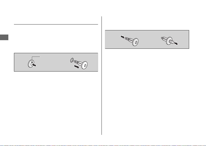
Removing & Installing Body Components u Clip
Clip
Removal
#
1.
Maintenance
Press down on the center pin to release
the lock.
2.
Pull the clip out of the hole.
Center pin
54
Installation
#
1.
Push the bottom of the center pin.
2.
Insert the clip into the hole.
3.
Press down on the center pin to lock the
clip.
Page 59
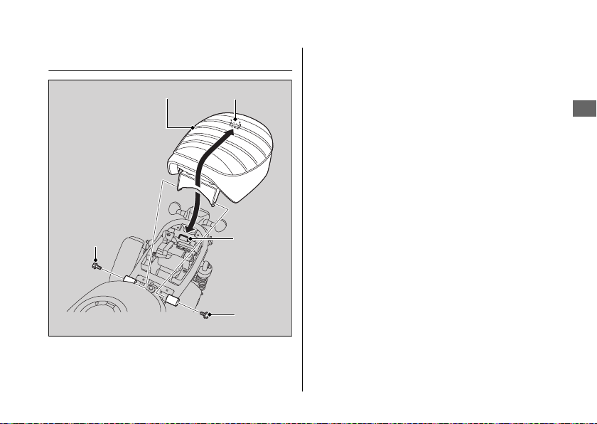
Seat
Seat
Prong
Removing & Installing Body Components u Seat
Removal
#
1.
Remove the bolts.
2.
Pull the seat up and backward.
Bolt
Stay
Bolt
Installation
#
1.
Insert the prong into the stay on the
frame.
2.
Push forward and down on the rear of the
seat until it locks in place.
3.
Install and tighten the bolts.
u Make sure that the seat is locked
securely in position to pull it up lightly.
Maintenance
55
Page 60
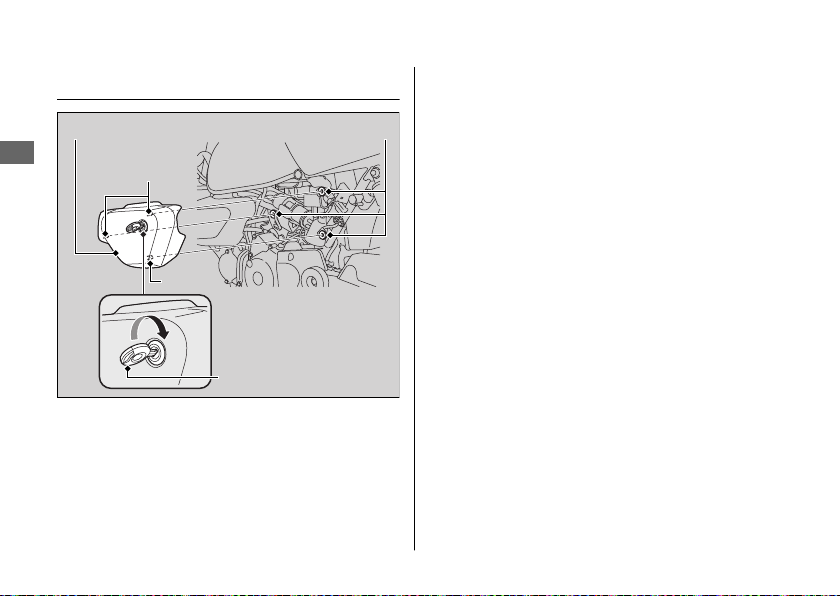
Removing & Installing Body Components u Left Side Cover
Left Side Cover
Left side cover
Maintenance
56
Prongs
Prong
Ignition key
Grommets
Removal
#
1.
Insert the ignition key into the lock.
2.
Carefully pull the left side cover out from
the grommets while turning the ignition
key clockwise.
Installation
#
1.
Align the prongs with the grommets.
2.
Push the left side cover into position while
turning the ignition key clockwise.
u Make sure that the left side cover is
locked securely in position by pulling it
lightly.
3.
Remove the ignition key.
Page 61
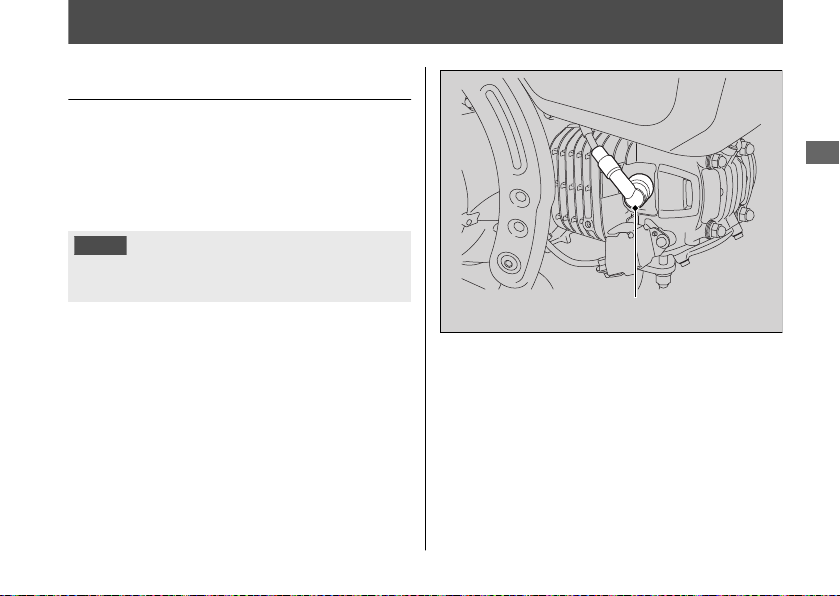
Spark Plug
Checking Spark Plug
For the recommended spark plug, see
“Specifications.” 2 P. 118
Use only the recommended type of spark
plug in the recommended heat range.
NOTICE
Using a spark plug with an improper heat range
can cause engine damage.
Disconnect the spark plug cap from the
1.
spark plug.
2.
Clean any dirt from around the spark plug
base.
3.
Remove the spark plug using a suitable
spark plug wrench.
Spark plug cap
4.
Inspect the electrodes and center
porcelain for deposits, erosion or carbon
fouling.
u If the erosion or deposit is heavy,
replace the plug.
u Clean a carbon or wet-fouled plug
with a plug cleaner, otherwise use a
wire brush.
Maintenance
Continued
57
Page 62
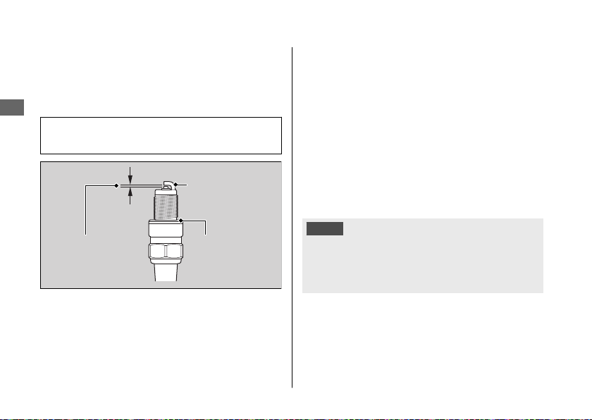
Spark Plug u Checking Spark Plug
5.
Check the spark plug gap using a wiretype feeler gauge.
u If adjustment is necessary, bend the
side electrode carefully.
Maintenance
The gap should be:
0.03 - 0.04 in (0.8 - 0.9 mm)
Spark plug gap
6.
Make sure the plug washer is in good
condition.
7.
Install the spark plug. With the plug
washer attached, thread the spark plug in
by hand to prevent cross-threading.
58
Side electrode
Plug washer
8.
Tighten the spark plug:
● If the old plug is good:
1/8 turn after it seats.
● If installing a new plug, tighten it twice
to prevent loosening:
a) First, tighten the plug:
NGK: 1/2 turn after it seats.
DENSO: 3/4 turn after it seats.
b) Then loosen the plug.
c) Next, tighten the plug again:
1/8 turn after it seats.
NOTICE
An improperly tightened spark plug can damage
the engine. If a plug is too loose, a piston may be
damaged. If a plug is too tight, the threads may
be damaged.
9.
Install the parts in the reverse order of
removal.
u When reinstalling the spark plug cap,
take care to avoid pinching any cables
or wires.
Page 63
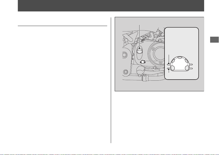
Engine Oil
Checking the Engine Oil
1.
If the engine is cold, idle the engine for 3
to 5 minutes.
2.
Turn the ignition switch to the OFF
position and wait for 2 to 3 minutes.
3.
Place your vehicle in an upright position
on a firm, level surface.
Check that the oil level is between the
4.
upper level and lower level marks on the
oil level inspection window.
Oil fill cap
Oil level
inspection
window
Upper level
Lower level
Maintenance
59
Page 64
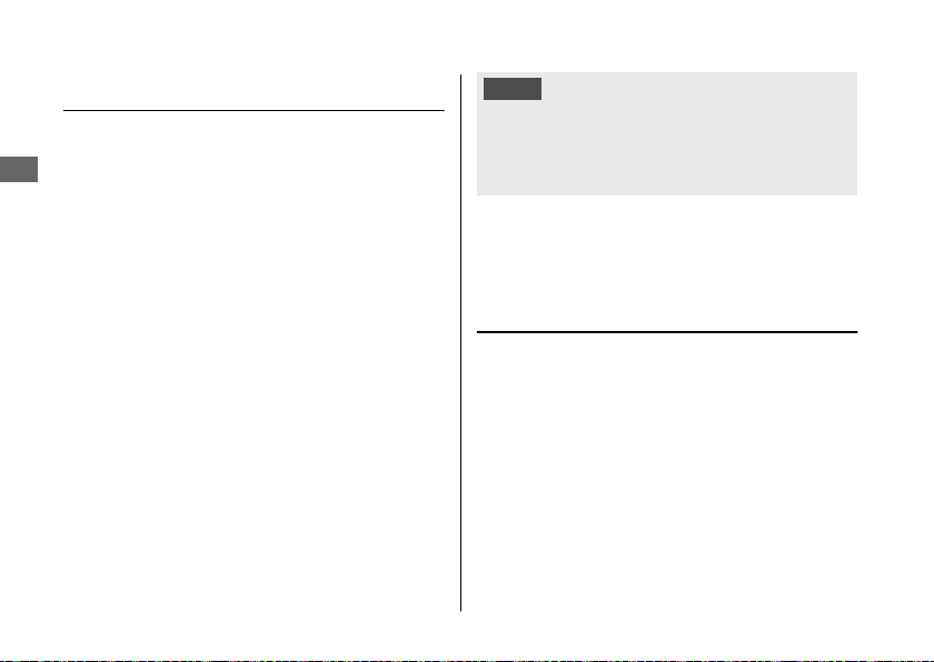
Engine Oil u Adding Engine Oil
Adding Engine Oil
If the engine oil is below or near the lower
level mark, add the recommended engine oil.
Maintenance
2 P. 44, 2 P. 118
1.
Remove the oil fill cap. Add the
recommended oil until it reaches the
upper level mark.
u Place your vehicle in an upright
position on a firm, level surface when
checking the oil level.
u Do not overfill above the upper level
mark.
u Make sure no foreign objects enter the
oil filler opening.
u Wipe up any spills immediately.
2.
Securely reinstall the oil fill cap.
60
NOTICE
Overfilling with oil or operating with insufficient
oil can cause damage to your engine. Do not mix
different brands and grades of oil. They may
affect lubrication and clutch operation.
For the recommended oil and oil selection
guidelines, see “Maintenance Fundamentals.”
2 P. 44
Changing Engine Oil
Changing the oil requires special tools. We
recommend that you have your vehicle
serviced by your dealer.
1.
If the engine is cold, idle the engine for 3
to 5 minutes.
2.
Turn the ignition switch to the OFF
position and wait for 2 to 3 minutes.
3.
Place your vehicle on a firm, level surface.
Page 65
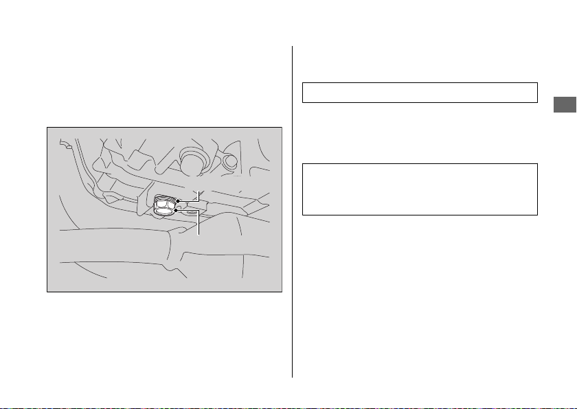
4.
Place a drain pan under the drain bolt.
5.
Remove the oil fill cap, drain bolt and
sealing washer to drain the oil.
u Discard the oil at an approved
recycling center.
Engine Oil u Changing Engine Oil
6.
Install a new sealing washer onto the
drain bolt. Tighten the drain bolt.
Torque: 18 lbf·ft (24 N·m, 2.4 kgf·m)
7.
Fill the crankcase with the recommended
oil (2 P. 44, 2 P. 118) and install the oil fill
cap.
Maintenance
Sealing washer
Drain bolt
Required oil
When changing oil:
1.0 US qt (0.9 L)
8.
Check the oil level. 2 P. 59
9.
Check that there are no oil leaks.
61
Page 66
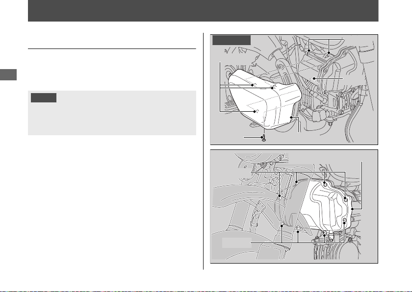
Air Cleaner
Changing Air Cleaner Element
Use a new Honda Genuine air cleaner
element or an equivalent specified for your
Maintenance
vehicle.
NOTICE
Using the wrong air cleaner element may cause
premature engine wear or performance
problems.
1.
Remove the screw.
2.
Remove the right garnish by releasing the
prongs from the slots.
u The right and left garnish removal can
be done in the same way.
3.
Remove the left garnish.
4.
Remove the air cleaner case cover by
removing the screws.
62
Right side
Prongs
Screw
Screws
Screws
Slots
Slot
Garnish
Air cleaner case cover
Page 67
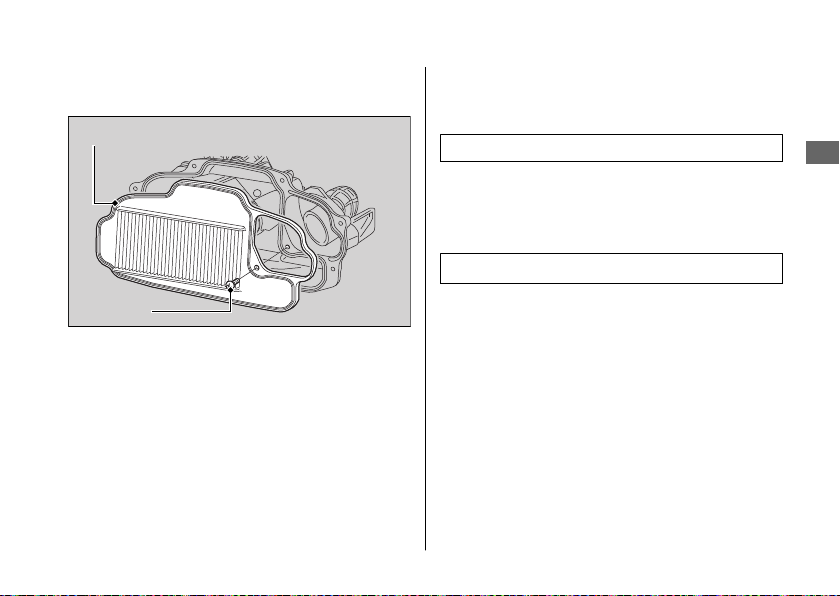
5.
Remove the air cleaner element by
removing the screw.
Air cleaner element
Screw
Air Cleaner u Changing Air Cleaner Element
6.
Install the new air cleaner element.
u Make sure the air cleaner element is
installed securely.
Torque: 0.8 lbf·ft (1.1 N·m, 0.1 kgf·m)
7.
Install the parts in the reverse order of
removal.
u Make sure the air cleaner case cover is
installed securely.
Torque: 0.8 lbf·ft (1.1 N·m, 0.1 kgf·m)
Maintenance
63
Page 68
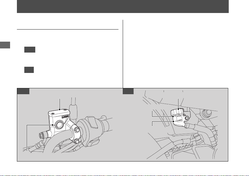
Brakes
Checking Brake Fluid
1.
Place your vehicle in an upright position
Maintenance
on a firm, level surface.
Front
2.
Check that the brake fluid reservoir is
horizontal and that the fluid level is above
the LOWER level mark.
Rear
Check that the brake fluid reservoir is
horizontal and that the fluid level is between
the LOWER level and UPPER level marks.
Front Rear
Front brake fluid reservoir
LOWER level mark
64
If the brake fluid level in either reservoir is
below the LOWER level mark or the brake
lever and pedal freeplay becomes excessive,
inspect the brake pads for wear.
If the brake pads are not worn, you most
likely have a leak. Have your vehicle
inspected by your dealer.
Rear brake fluid reservoir
UPPER level mark
LOWER level mark
Page 69
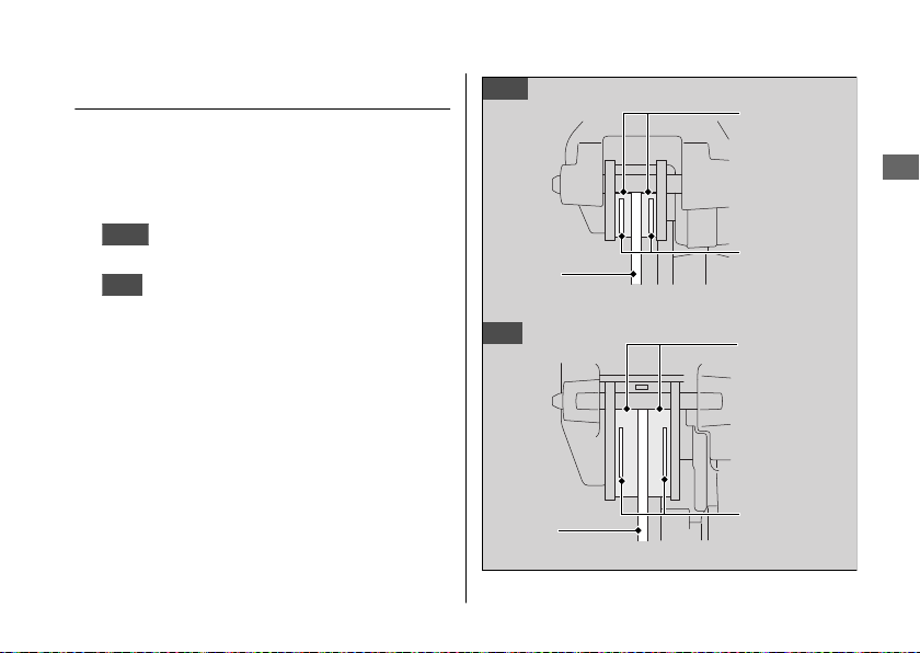
Brakes u Inspecting the Brake Pads
Inspecting the Brake Pads
Check the condition of the brake pad wear
indicators.
The pads need to be replaced if a brake pad
is worn to the indicator.
Front
1.
2.
If necessary have the pads replaced by your
dealer.
Always replace both left and right brake pads
at the same time.
Inspect the brake pads from below
the brake caliper.
Rear
Inspect the brake pads from the rear
right of the vehicle.
Front
Rear
Disc
Disc
Brake pads
Maintenance
Wear
indicators
Brake pads
Wear
indicators
65
Page 70
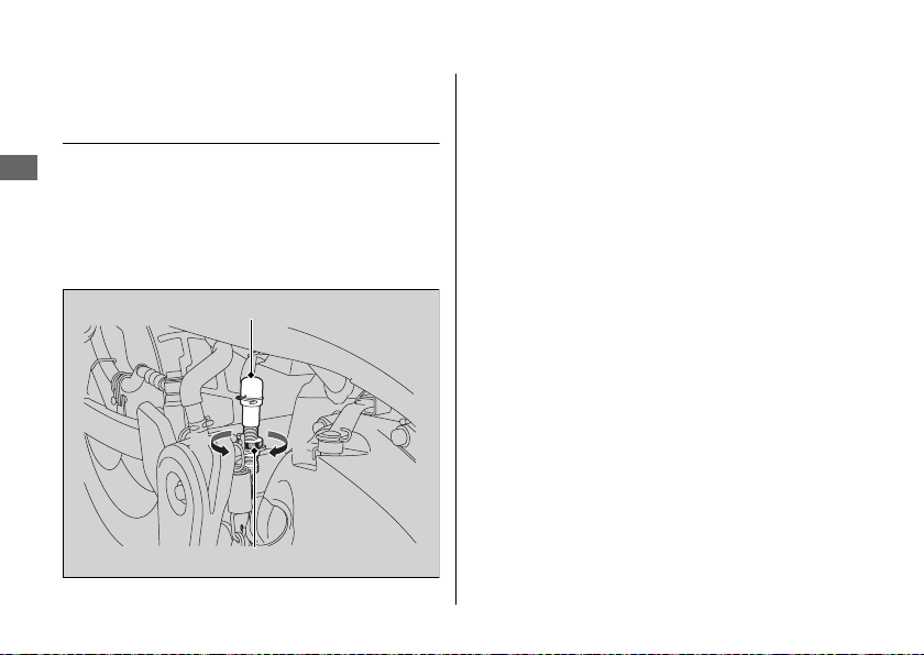
Brakes u Adjusting the Brake Light Switch
Adjusting the Brake Light
Switch
Check the operation of the brake light switch.
Maintenance
Hold the brake light switch and turn the
adjusting nut in the direction A if the switch
operates too late, or turn the nut in the
direction B if the switch operates too soon.
Brake light switch
B A
Adjusting nut
66
Page 71
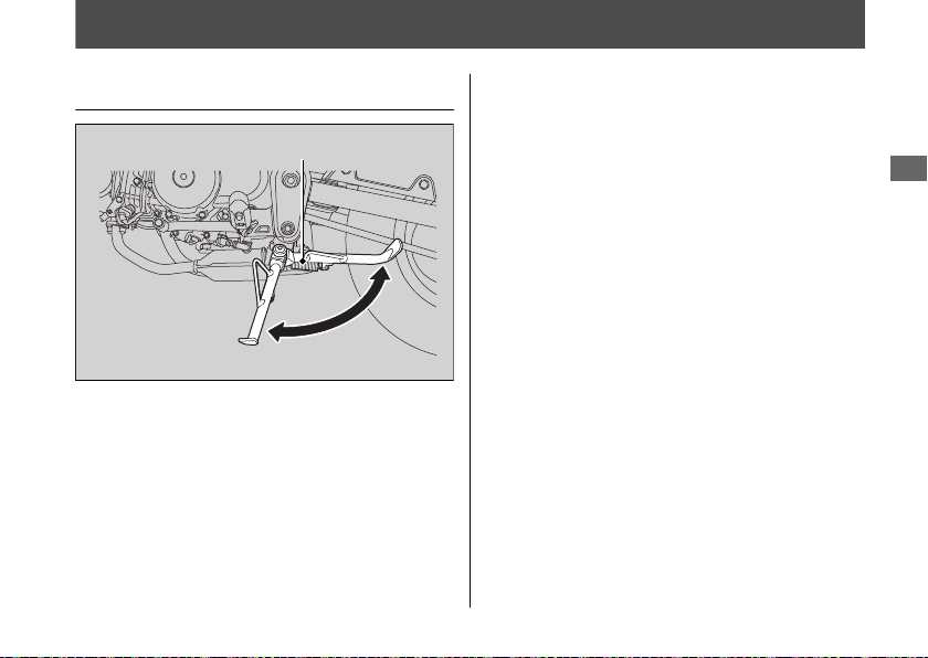
Side Stand
Checking the Side Stand
Side stand spring
1.
Check that the side stand operates
smoothly. If the side stand is stiff or
squeaky, clean the pivot area and
lubricate the pivot bolt with clean grease.
2.
Check the spring for damage or loss of
tension.
3.
Sit on the vehicle, shift the transmission to
Neutral, and raise the side stand.
4.
Start the engine, pull the clutch lever in,
and shift the transmission into gear.
5.
Lower the side stand all the way. The
engine should stop as you lower the side
stand. If the engine doesn't stop, have
your vehicle inspected by your dealer.
Maintenance
67
Page 72
Drive Chain
Inspecting the Drive Chain
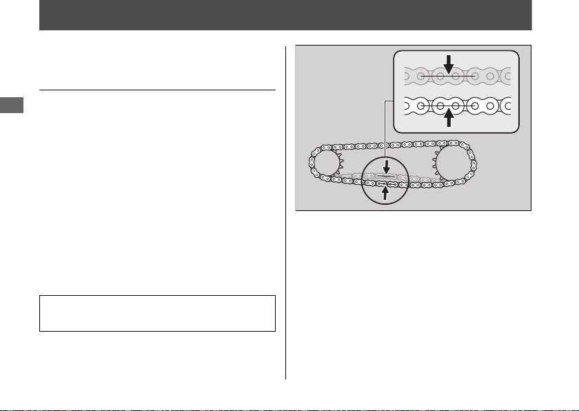
Slack
Check the drive chain slack at several points
Maintenance
along the chain. If the slack is not constant at
all points, some links may be kinked and
binding.
Have the chain inspected by your dealer.
1.
Shift the transmission to Neutral. Stop the
engine.
2.
Place your vehicle on its side stand on a
firm, level surface.
3.
Check the slack in the lower half of the drive
chain midway between the sprockets.
Drive chain slack:
1 3/16 - 1 9/16 in (30 - 40 mm)
u Do not ride your vehicle if the slack
exceeds 1 15/16 in (50 mm).
68
4.
Roll the vehicle forward and check that
the chain moves smoothly.
5.
Inspect the sprockets. 2 P. 45
6.
Clean and lubricate the drive chain.
2 P. 46
Page 73
Drive Chain u Adjusting the Drive Chain Slack
Adjusting the Drive Chain Slack
Adjusting the chain requires special tools.
Have the drive chain slack adjusted by your
dealer.
1.
Shift the transmission to Neutral. Stop the
engine.
Place your vehicle on its side stand on a
2.
firm, level surface.
3.
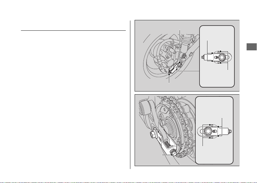
Loosen the rear axle nut.
Rear axle nut
Adjusting bolt
Adjusting
bolt
Chain adjuster
index marks
Triangle marks
Chain adjuster
index marks
Triangle marks
Continued
Maintenance
69
Page 74
Drive Chain u Adjusting the Drive Chain Slack
4.
Turn both adjusting bolts an equal
number of turns until the correct drive
chain slack is obtained. Turn the adjusting
bolts counterclockwise to tighten the
Maintenance
chain. Turn the adjusting bolts clockwise
to provide more slack.
Adjust the slack at a point midway
between the drive sprocket and the
driven sprocket.
Check the drive chain slack. 2 P. 68
5.
Check rear axle alignment by making sure
the chain adjuster index marks align with
the triangle marks.
Both marks should correspond. If the axle
is misaligned, turn the right or left
adjusting bolts until the marks are aligned
and recheck chain slack.
70
6.
Tighten the rear axle nut.
Torque: 44 lbf·ft (59 N·m, 6.0 kgf·m)
7.
Tighten the drive chain adjusting bolts
lightly.
8.
Recheck drive chain slack.
If a torque wrench was not used for
installation, see your dealer as soon as
possible to verify proper assembly.
Improper assembly may lead to loss of
braking capacity.
Page 75
Checking the Drive Chain Wear
#
If the drive chain slack is excessive when the
rear axle is moved to the furthest limit of
adjustment, the drive chain is worn and must
be replaced.
Drive Chain u Adjusting the Drive Chain Slack
Maintenance
Chain: DID 420D2
If necessary have the drive chain replaced by
your dealer.
or RK 420SB2TK
71
Page 76
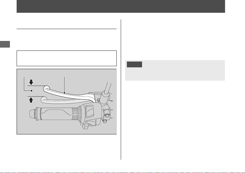
Clutch
Checking the Clutch
Checking the Clutch Lever Freeplay
#
Check the clutch lever freeplay.
Maintenance
Freeplay at the clutch lever:
3/8 - 13/16 in (10 - 20 mm)
Clutch leverFreeplay
72
Check the clutch cable for kinks or signs of
wear. If necessary have it replaced by your
dealer.
Lubricate the clutch cable with a
commercially available cable lubricant to
prevent premature wear and corrosion.
NOTICE
Improper freeplay adjustment can cause
premature clutch wear.
Page 77
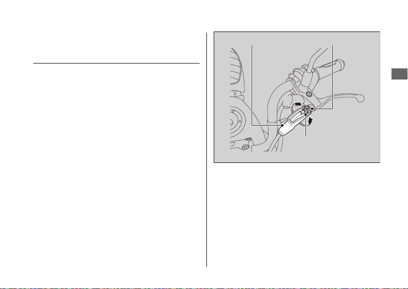
Clutch u Adjusting the Clutch Lever Freeplay
Adjusting the Clutch Lever
Freeplay
Upper Adjustment
#
Attempt adjustment with the upper clutch
cable adjuster first.
1.
Pull back the rubber dust cover.
2.
Loosen the upper lock nut.
3.
Turn the upper clutch cable adjuster until
the freeplay is 3/8 - 13/16 in (10 - 20 mm).
4.
Tighten the upper lock nut and check the
freeplay again.
5.
Reinstall the rubber dust cover.
Rubber dust cover
Lower Adjustment
#
If the upper clutch cable adjuster is threaded
out near its limit, or the correct freeplay
cannot be obtained, attempt adjustment with
the lower clutch cable adjusting nut.
Upper lock nut
+
–
Upper clutch cable
adjuster
Continued
Maintenance
73
Page 78
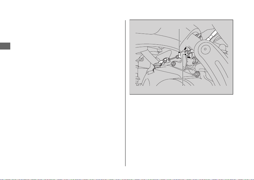
Clutch u Adjusting the Clutch Lever Freeplay
1.
Loosen the upper lock nut and turn the
upper clutch cable adjuster all the way in
(to provide maximum freeplay). Tighten
the upper lock nut.
Maintenance
2.
Loosen the lower lock nut.
3.
Turn the lower clutch cable adjusting nut
until the clutch lever freeplay is 3/8 - 13/16
in (10 - 20 mm).
4.
Tighten the lower lock nut and check the
clutch lever freeplay.
5.
Start the engine, pull the clutch lever in,
and shift into gear. Make sure the engine
does not stall and the vehicle does not
creep. Gradually release the clutch lever
and open the throttle. Your vehicle should
move smoothly and accelerate gradually.
74
Lower lock nut
+
–
Lower clutch cable adjusting nut
If proper adjustment cannot be obtained or
the clutch does not work correctly, see your
dealer.
Page 79
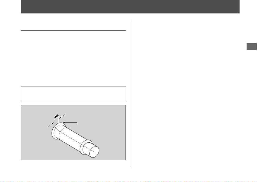
Throttle
Checking the Throttle
With the engine off, check that the throttle
rotates smoothly from fully closed to fully
open in all steering positions and throttle
freeplay is correct. If the throttle does not
move smoothly, close automatically, or if the
cable is damaged, have the vehicle inspected
by your dealer.
Freeplay at the throttle grip flange:
1/16 - 1/4 in (2 - 6 mm)
Freeplay
Flange
Maintenance
75
Page 80
Crankcase Breather
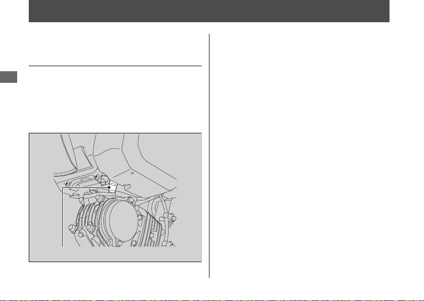
Cleaning the Crankcase
Breather
1.
Maintenance
Place a suitable container to receive
deposits.
2.
Remove the crankcase breather tube and
drain deposits.
Reinstall the crankcase breather tube.
3.
Crankcase breather tube
76
Page 81
Other Adjustments
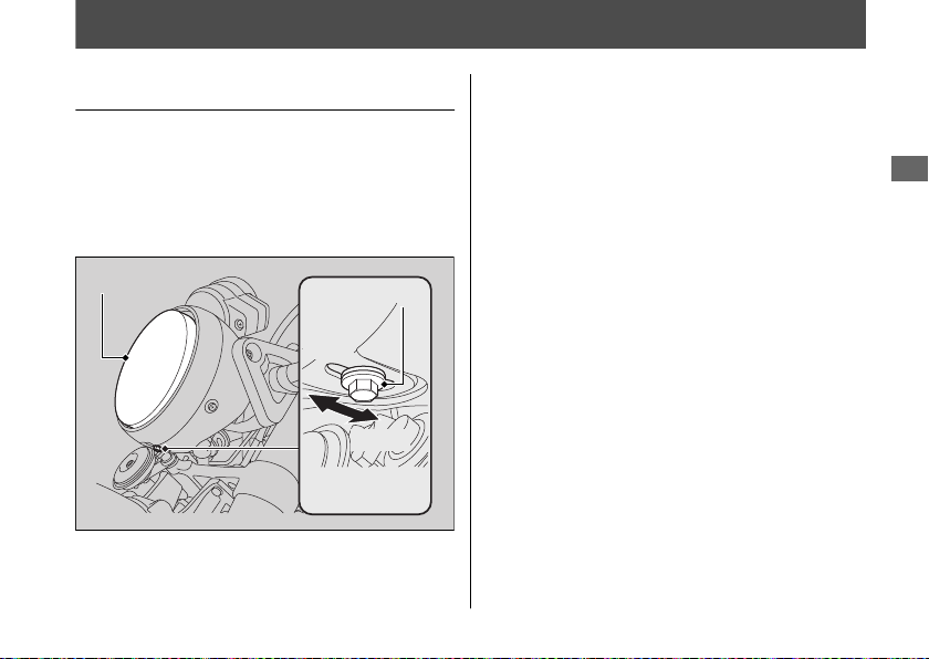
Adjusting the Headlight Aim
You can adjust vertical aim of the headlight
for proper alignment. To move the headlight,
loosen the adjusting bolt.
Tighten the adjusting bolt after adjustment.
Obey local laws and regulations.
Maintenance
Headlight
Adjusting bolt
Raise
Lower
77
Page 82

Troubleshooting
Engine Will Not Start........................................ P. 79
Warning Indicators On or Flashing
PGM-FI (Programmed Fuel Injection)
Malfunction Indicator Lamp (MIL).................P. 80
ABS (Anti-lock Brake System) Indicator .........P. 81
Other Warning Indications.............................. P. 82
Fuel Gauge Failure Indication...........................P. 82
Tire Puncture ...................................................... P. 83
Electrical Trouble............................................... P. 89
Battery Goes Dead .............................................. P. 89
Burned-out Light Bulb........................................ P. 89
Blown Fuse ............................................................ P. 93
Unstable Engine Operation Occurs
Intermittently ...................................................P. 94
............... P. 80
Page 83
Engine Will Not Start
Starter Motor Operates But
Engine Does Not Start
Check the following items:
● Check the correct engine starting
sequence. 2 P. 25
● Check that there is gasoline in the fuel
tank.
● Check if the PGM-FI malfunction indicator
lamp (MIL) is on.
u If the indicator lamp is on, contact
your dealer as soon as possible.
Starter Motor Does Not
Operate
Check the following items:
● Check the correct engine starting
sequence. 2 P. 25
● Make sure engine stop switch is in the
(Run) position. 2 P. 22
● Check for a blown fuse. 2 P.
● Check for a loose battery connection
(2 P. 53) or battery terminal corrosion
(2 P. 41).
● Check the condition of the battery.
2 P. 89
If the problem continues, have your vehicle
inspected by your dealer.
93
Troubleshooting
79
Page 84
Warning Indicators On or Flashing
PGM-FI (Programmed Fuel
Injection) Malfunction
Indicator Lamp (MIL)
If the indicator comes on while riding, you
Troubleshooting
may have a serious problem with the PGM-FI
system. Reduce speed and have your vehicle
inspected by your dealer as soon as possible.
80
Page 85
Warning Indicators On or Flashing u ABS (Anti-lock Brake System) Indicator
ABS (Anti-lock Brake System)
Indicator
Monkey125A only
If the indicator operates in one of the
following ways, you may have a serious
problem with the ABS. Reduce your speed
and have your vehicle inspected by your
dealer as soon as possible.
● Indicator comes on or starts flashing while
riding.
● Indicator does not come on when the
ignition switch is in the
● Indicator does not go off at speeds above
6 mph (10 km/h).
ON position.
If the ABS indicator stays on, your brakes will
continue to work as a conventional system,
but without the anti-locking function.
The ABS indicator may flash if you turn the
rear wheel while the rear wheel is lifted off
the ground. In this case, turn the ignition
switch to the OFF position, and then to the
ON position again. The ABS indicator will go
off after your speed reaches 19 mph (30
km/h).
Troubleshooting
81
Page 86
Other Warning Indications
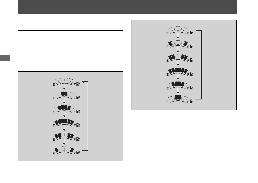
Fuel Gauge Failure Indication
If the fuel system has an error, the fuel gauge
indicators will be displayed as shown in the
illustration.
If this occurs, see your dealer as soon as
Troubleshooting
possible.
82
Page 87
Tire Puncture
Repairing a puncture or removing a wheel
requires special tools and technical expertise.
We recommend you have this type of service
performed by your dealer.
After an emergency repair, always have the
tire inspected/replaced by your dealer.
Emergency Repair Using a Tire
Repair Kit
If your tire has a minor puncture, you can
make an emergency repair using a tubeless
tire repair kit.
Follow the instructions provided with the
emergency tire repair kit.
Riding your vehicle with a temporary tire
repair is very risky. Do not exceed 30 mph
(50 km/h). Have the tire replaced by your
dealer as soon as possible.
3WARNING
Riding your vehicle with a temporary
tire repair can be risky. If the temporary
repair fails, you can crash and be
seriously injured or killed.
If you must ride with a temporary tire
repair, ride slowly and carefully and do
not exceed 30 mph (50 km/h) until the
tire is replaced.
Removing Wheels
Follow these procedures if you need to
remove a wheel in order to repair a
puncture.
Monkey125A only
When removing and installing the wheel, be
careful not to damage the wheel speed
sensor and pulser ring.
Continued
Troubleshooting
83
Page 88
Tire Puncture u Removing Wheels
Front Wheel
#
Removal
1.
Place your vehicle on a firm, level surface.
2.
Support your vehicle securely and raise
the front wheel off the ground using a
Troubleshooting
maintenance stand or a hoist.
3.
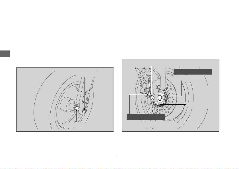
Remove the front axle nut.
84
Front axle nut
Side collar
4.
Remove the front axle shaft, front wheel
and side collars.
u Avoid getting grease, oil, or dirt on the
disc or pad surfaces.
u Do not pull the brake lever while the
front wheel is removed.
Front axle shaft
Monkey125A only
Pulser ring
Side collar
Monkey125A only
Wheel speed sensor
Page 89
Tire Puncture u Removing Wheels
Installation
1.
Attach the side collars to the wheel.
2.
Position the wheel between the fork legs
and insert the front axle shaft from the
right side, through the wheel hub and
right fork leg.
NOTICE
When installing a wheel or caliper into original
position, carefully fit the brake disc between the
pads to avoid scratching them.
3.
Tighten the front axle nut.
Torque: 51 lbf·ft (69 N·m, 7.0 kgf·m)
4.
After installing the wheel, apply the brake
lever several times, then check if the
wheel rotates freely. Recheck the wheel if
the brake drags or if the wheel does not
rotate freely.
If a torque wrench was not used for
installation, see your dealer as soon as
possible to verify proper assembly.
Improper assembly may lead to loss of
braking capacity.
Continued
Troubleshooting
85
Page 90
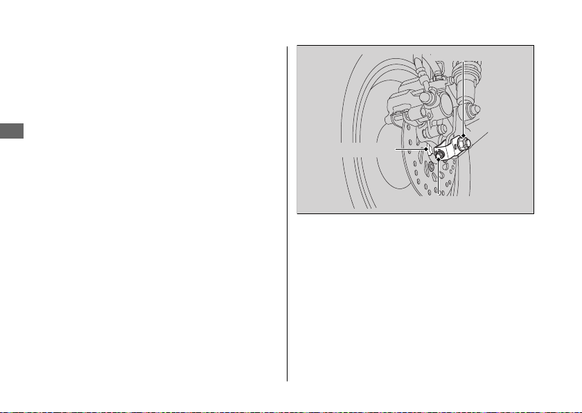
Tire Puncture u Removing Wheels
Rear Wheel
#
Removal
1.
Support your vehicle securely and raise
the rear wheel off the ground using a
maintenance stand or a hoist.
2.
Troubleshooting
Loosen the rear axle nut and turn the
adjusting bolts so the rear wheel can be
moved all the way forward for maximum
drive chain slack.
3.
Remove the rear axle nut.
86
Rear axle nut
Right side collar
Adjusting bolt
Page 91
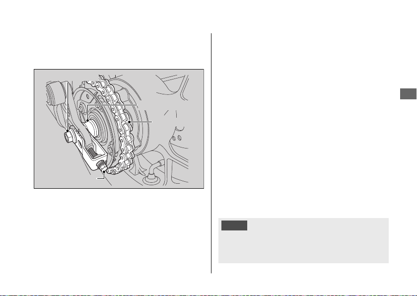
4.
Remove the drive chain from the driven
sprocket by pushing the rear wheel
forward.
Rear axle shaft
Left side collar
Drive chain
Adjusting bolt
Tire Puncture u Removing Wheels
5.
Remove the rear axle shaft, right side
collar, left side collar and rear wheel.
u Support the brake caliper assembly so
that it doesn’t hang from the brake
hose. Do not twist the brake hose.
u Avoid getting grease, oil, or dirt on the
disc or pad surfaces.
u Do not push the brake pedal while the
brake caliper assembly is removed.
Installation
1.
To install the rear wheel, reverse the
removal procedure.
u Take care to prevent the brake caliper
from scratching the wheel during
installation.
NOTICE
When installing a wheel or caliper into original
position, carefully fit the brake disc between the
pads to avoid scratching them.
Troubleshooting
Continued
87
Page 92
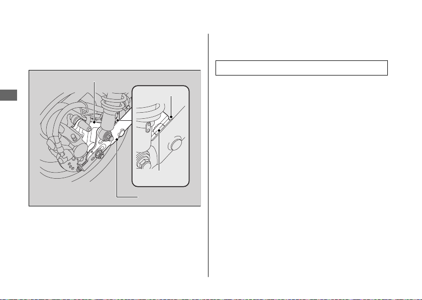
Tire Puncture u Removing Wheels
2.
Make sure that the lug on the swingarm is
positioned in the slot on the brake caliper
bracket.
Brake caliper bracket
Troubleshooting
88
Slot
Lug
Swingarm
3.
Adjust the drive chain slack. 2 P. 69
4.
Install and tighten the rear axle nut.
Torque: 44 lbf·ft (59 N·m, 6.0 kgf·m)
5.
After installing the wheel, apply the brake
pedal several times, then check if the
wheel rotates freely. Recheck the wheel if
the brake drags or if the wheel does not
rotate freely.
If a torque wrench was not used for
installation, see your dealer as soon as
possible to verify proper assembly.
Improper assembly may lead to loss of
braking capacity.
Page 93
Electrical Trouble
Battery Goes Dead
Charge the battery using a motorcycle
battery charger.
Remove the battery from the vehicle before
charging.
Do not use an automobile-type battery
charger, as these can overheat a motorcycle
battery and cause permanent damage. If the
battery does not recover after recharging,
contact your dealer.
NOTICE
Jump starting using an automobile battery can
damage your vehicle's electrical system and is
not recommended.
Bump starting is also not recommended.
Burned-out Light Bulb
Follow the procedure below to replace a
burned-out light bulb.
Turn the ignition switch to the OFF or LOCK
position.
Allow the bulb to cool before replacing it.
Do not use bulbs other than those specified.
Check the replacement bulb for correct
operation before riding.
For the light bulb wattage, see
“Specifications.” 2 P. 119
Continued
Troubleshooting
89
Page 94
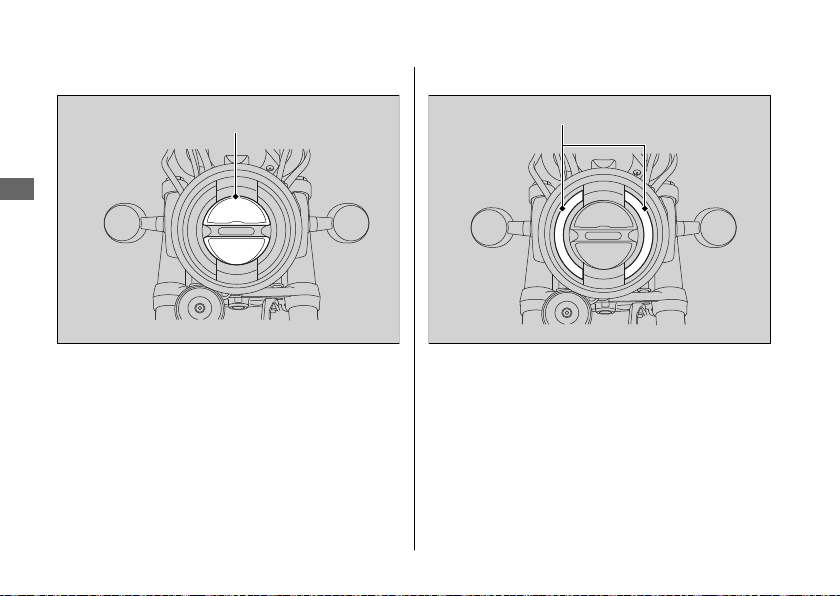
Electrical Trouble u Burned-out Light Bulb
Headlight
#
Headlight
Troubleshooting
The headlight uses several LEDs.
If there is an LED which is not turned on, see
your dealer for servicing.
90
Position Light
#
Position light
The position light uses an LED.
If there is an LED which is not turned on, see
your dealer for servicing.
Page 95
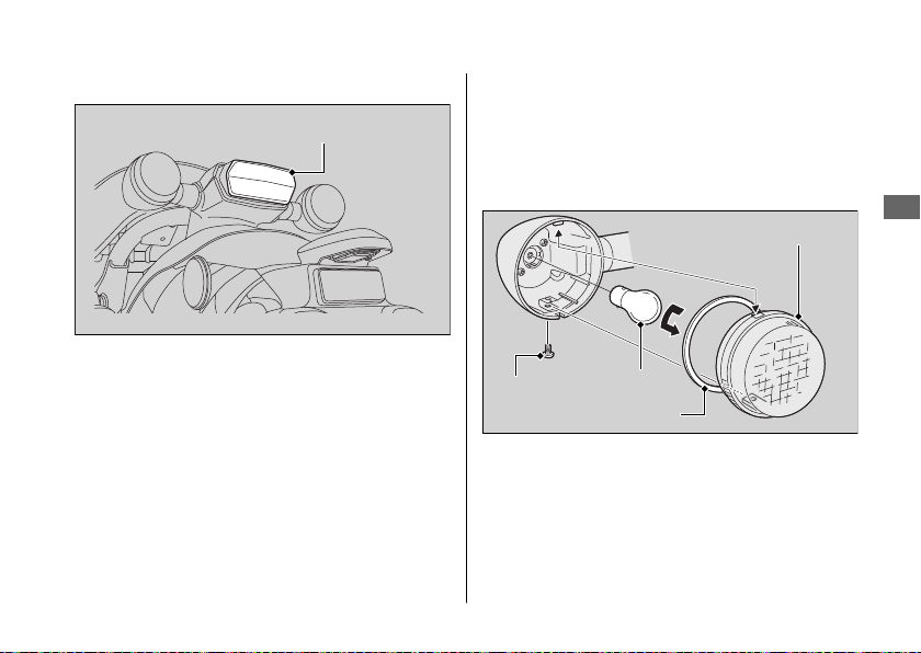
Electrical Trouble u Burned-out Light Bulb
Brake light/Taillight
#
Brake light/Taillight
The brake light and taillight uses several
LEDs.
If there is an LED which is not turned on, see
your dealer for servicing.
Front/Rear Turn Signal Bulb
#
1.
Remove the screw.
2.
Remove the turn signal lens.
3.
Slightly press the bulb in and turn it
counterclockwise.
Turn signal lens
Screw
Lens packing
4.
Install a new bulb and the parts in the
reverse order of removal.
u After putting back the lens packing in
place, install the turn signal lens.
Bulb
Continued
Troubleshooting
91
Page 96
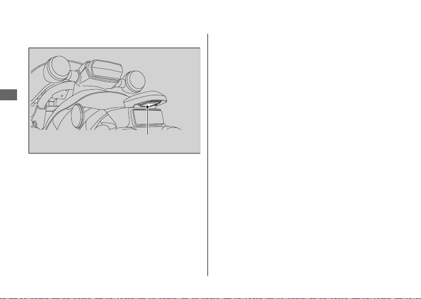
Electrical Trouble u Burned-out Light Bulb
License Plate Light
#
Troubleshooting
License plate light
The license plate light uses an LED.
If there is an LED which is not turned on, see
your dealer for servicing.
92
Page 97

Electrical Trouble u Blown Fuse
Blown Fuse
Before handling fuses, see “Inspecting and
Replacing Fuses.” 2 P. 43
Fuse Box Fuses
#
1.
Remove the seat. 2 P. 55
2.
Remove the fuse box cover.
3.
Pull the fuses out one by one with the
fuse puller in the tool kit and check for a
blown fuse. Always replace a blown fuse
with a spare fuse of the same rating.
u Spare fuses are provided near the
battery.
Reinstall the fuse box cover.
4.
Reinstall the seat.
5.
NOTICE
If a fuse fails repeatedly, you likely have an
electrical problem. Have your vehicle inspected
by your dealer.
Fuse box cover
Troubleshooting
Spare fuses
93
Page 98
Unstable Engine Operation Occurs Intermittently
If the fuel pump filter is clogged, unstable
engine operation will occur intermittently
while riding.
Even if this symptom occurs, you can
continue to ride your vehicle.
If unstable engine operation occurs even if
Troubleshooting
sufficient fuel is available, have your vehicle
inspected by your dealer as soon as possible.
94
Page 99

Information
Keys....................................................................... P. 96
Instruments, Controls, & Other Features
Caring for Your Vehicle.................................... P. 99
Storing Your Vehicle....................................... P. 102
Transporting Your Vehicle ............................ P. 103
You & the Environment .................................P. 104
Vehicle Identification Number..................... P. 105
Emission Control Systems ............................. P. 106
Catalytic Converter .........................................P. 110
Oxygenated Fuels............................................ P. 111
Authorized Manuals .......................................P. 112
Warranty Coverage and Service .................. P. 113
Honda Contacts ............................................... P. 114
Reporting Safety Defects ..............................P. 116
..... P. 97
Page 100
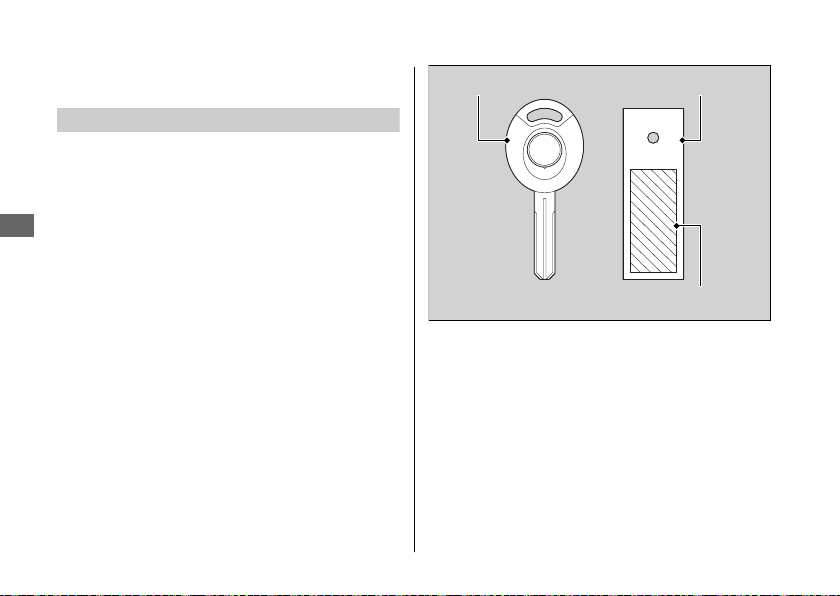
Keys
Keys
Ignition Key
This vehicle has two ignition keys and a key tag
with a key number and a bar code. Store the
spare key and the key tag in a safe location. To
make a duplicate key, take the spare key and
the key tag to your dealer or a locksmith.
Information
If you lose all ignition keys and the key tag, the
ignition switch assembly will probably have to
be removed by your dealer to determine the
key number.
A metal key holder may cause damage to the
area surrounding the ignition switch.
96
Ignition key
Key tag
Key number and bar code
 Loading...