

Honda MM60 Operator's Manual


INTRODUCTION
TO
THE
OWNER
Read this manual before operating your mower. The information presented
and safer job, Keep this manual handy for ready reference.
The mower you have purchased has been carefully engineered and manufactured
-
and satisfactory use, Like all mechanical products, it
will
require cleaning and upkeep. Lubricate the
mower as specified. Observe all safety information in this manual and safety decals on the mower and
tractor.
For
service, your authorized dealer has trained mechanics, genuine service parts, and the necessary tools
and equipment to handle all your needs.
Use only genuine service parts. Substitute parts may not meet standards required for safe and satisfactory
operation.
Model MM60 Rotary Mower
Record the serial number of your mower:
Serial Number (see Safety Decal page for location)
to
Provide this information to your dealer
obtain correct repair parts.
will
prepare you to do a better
to
provide dependable
Throughout this manual, the term NOTICE
is
used to indicate that failure to observe this instruction can
cause damage to equipment. The terms CAUTION, WARNING and DANGER are used in conjunction with
-
the Safety
Alert Symbol, (a triangle with an exclamation mark), to indicate the degree of hazard for items of
personal safety.
The Safety-Alert Symbol means ATTENTION! BECOME ALERT!
YOUR SAFETY IS INVOLVED!
Denotes a reminder of safety practices or directs attention to unsafe practices
which could result in personal injury if proper precautions are not taken.
!
1-
Denotes a hazard exists which can result in injury or death if proper precautions
are not taken.
#.
of death or irreparable injury
Denotes an extreme intrinsic hazard exists which would result in high probability
if proper precautions are not taken.
1

INTRODUCTION
GENERAL
The purpose of this manual is to assist the opera
INFORMATlON
tor in maintaining and operating this mower. Read
it carefully. It furnishes information and instructions
of
that will help you achieve years
dependable
performance. These operating and maintenance
instructions have been compiled from extensive
field experience and engineering data. Some
information may be general in nature due to
unknown and varying conditions. However, you
should be able to develop operating procedures
suitable to your particular situation.
The illustrations and data used in this manual were
current at the time of printing, but due to possible
-
line production changes, your machine may
in
vary slightly in detail. We reserve the right
to
redesign and change the machine as may be
necessary without notification.
1-
show the mower with safety shields removed
to provide a better view. The mower should
never be operated with any safety shielding
removed.
Some illustrations in this manual
,
Throughout this manual, references are made
to
right and left directions. These are determined by
standing behind the equipment and facing the
is
direction of forward travel. Blade rotation
clock
wise as viewed from the top of the mower.
-

CONTENTS
INTRODUCTION
TO THE OWNER
GENERAL INFORMATION
SAFETY INFORMATION
SAFETY RULES
SET-UP AND ASSEMBLY
DEALER SET-UP INSTRUCTIONS
UNPACKING AND CHECKING PARTS
MOUNTING MOWER LIFT SYSTEM
ASSEMBLING MOWER
INSTALLING MOWER
INSTALLING MOWER TO TRACTOR
DETACHING MOWER FROM TRACTOR
OPERATION
ADJUSTING CUTTING HEIGHT
PRE-OPERATION CHECK LIST
OPERATING TECHNIQUE
CUTTING PATTERNS
OPERATING YOUR MOWER WITH OTHER EQUIPMENT
...........................................................................................................................
............................................................................................................
.............................................................................................................................
.............................................................................................
........................................................................................
..........................................................................................
..............................................................................................................
.........................................................................................
...................................................................................
.................................................................................................
.................................................................................................
..........................................................................................................
.................................................................................................................
........................................................
1
1
2
4
4
8
8
8
11
17
18
21
25
28
29
30
31
32
33
MAINTENANCE 36
OWNER SERVICE
LUBRICATION INFORMAllON
BLADE INSPECTION
BLADE SERVlClNG
REPLACING BELTS
DEALER LEVEL MAINTENANCE
SPINDLE REPAIR
UNIVERSAL JOINT REPAIR
GEARBOX MAINTENANCE
STORAGE
TROUBLESHOOTING
SPECIFICATIONS
WARRANTY SERVICE
.......................................................................................................................
......................................................................................................
..................................................................................................................
.....................................................................................................................
....................................................................................................................
...................................................................................
.........
.......................................................................................................................
.......................................................................................................
........................................................................................................
36
37
38
39
41
42
43
47
49
52
53
55
56
3

SAFETY INFORMATION
Safety
manufacture of our products. Unfortunately,
our efforts to provide safe equipment can be
wiped out by a single careless act of an
operator.
In addition to the design and configuration of
equipment, hazard control and accident
prevention are dependent upon the aware
ness, concern, prudence and proper training
of personnel involved in the operation, trans
port, maintenance and storage of equipment.
It has been said, "The best safety device is
an informed, careful operato
be that kind of an operator.
is
a primary concern in the design and
r." We ask you to
-
-
SAFETY RULES
ATTENTION! BECOME ALERT!
YOUR SAFETY
The designed and tested safety of this equipment
depends on it being operated within the limitations
explained in this manual.
IS
INVOLVED!
Training
Safety instructions are important! Read this
manual, the tractor manual and all safety rules.
Know your controls and how to stop tractor
engine and mower quickly in an emergency.
Operators must be instructed in and be ca
pable of the safe operation of the equipment, its
Do
attachments and all controls.
anyone
proper instructions,
Keep hands and body away from pressurized
lines. Use paper
to check for leaks. Hydraulic fluid (oil) under
pressure will penetrate skin causing serious
injury.
Make sure that all operating and service per
sonnel know that in the event hydraulic fluid
penetrates skin, it must be surgically removed
within a few hours by a doctor familiar with this
form of injury,
Do not allow children or unqualified persons to
operate equipment.
to
operate this equipment without
or
cardboard, not body parts
or
gangrene may result.
not allow
-
-
4

SAFETY
INFORMATION
Preparation
Always wear relatively tight and belted clothing
to avoid entanglement in moving parts. Wear
sturdy, rough
equipment for eyes, hands, hearing and head.
Ensure that mower is properly mounted, ad
justed and in good, operating Condition.
Make sure mower driveline spring-activated
locking collar slides freely and the balls are
seated in mid
Remove accumulated debris from mower to
avoid
Ensure all safety decals are installed and in
good condition. (See Safety Decals section for
location drawing.)
:
Ensure shields and guards are properly in
stalled and in good condition.
A
minimum
weight must be on tractor front wheels with
mower in transport position. Without this
weight, tractor could tip over causing personal
injury
front wheel weights, ballast in tires
tractor weights. When attaining the minimum
20%
exceed the Roll Over Protection Structure
(ROPS)
and equipment.
Inspect area to be cut and remove stones,
branches
thrown, causing injury
-
soled work shoes and protective
-
PTO shaft groove.
fire
hazard.
20%
of tractor and equipment
or
death. The weight may be attained with
or
front
weight on the front wheels, you must not
weight certification. Weigh the tractor
Do
not estimate.
or
other hard objects that might be
or
damage.
Operational Safety
You may not be able to stop the tractor safely
the clutch or brake pedal mechanisms are
improperly adjusted, allowing them to contact
mower components.
-
-
When the mower lift stops are installed as
instructed in this manual, properly adjusted
will
clutch and brake pedal mechanisms
contact mower components. You should
frequently check that the tractor clutch and
brake pedal mechanisms are in adjustment.
If the clutch
contact mower components, do not operate
until properly adjusted.
Do not operate mower unless discharge chute
is
installed.
Keep bystanders away from equipment while it
is
in operation.
Never direct discharge toward anyone.
Operate only in daylight or good artificial light.
Keep hands and feet away from mower while
tractor engine is running.
Stay clear of all moving parts.
If your tractor is equipped with a
must wear your seat belt.
No
riders are allowed on tractor
Start engine from operator's seat after disen
gaging tractor PTO and placing transmission in
neutral.
Always sit in tractor seat when starting the
engine or operating controls.
Disengage power-take-off , shift tractor into
neutral, and place all controls in neutral before
starting tractor engine.
Operate tractor mid-PTO at no more than
RPM
(maximum governed engine
Make sure area behind'you
operating in reverse.
Do
not operate on steep slopes.
Do
not stop, start or change directions sud
denly on slopes.
Use extreme care and reduce ground speed
on slopes and rough terrain.
Watch for hidden hazards on the terrain during
operation.
or
brake pedal mechanisms can
ROPS,
or
RPM).
is
clear before
not
you
mower.
if
-
2400
-
5

SAFETY INFORMATION
Stop mower and tractor immediately upon
striking an obstruction. Turn
key, inspect and repair any damage before
resuming operation.
Before working underneath, raise mower, install
transport lock and block mower securely.
Hydraulic system leak down and failure of
mechanical or hydraulic system can cause
equipment to drop.
Disengage power to mower, lower mower to
ground, stop engine, set parking brake and
remove key before dismounting tractor.
Maintenance Safety
Always wear relatively tight and belted clothing
to avoid entanglement in moving parts. Wear
-
sturdy, rough
equipment for eyes, hands, hearing and head.
Lower mower to ground or block securely, turn
tractor engine
mower U-joint driveline from tractor
performing any service or maintenance.
Never perform service or maintenance with
tractor engine running.
Before working underneath, raise mower, install
transport lock and block mower securely.
Hydraulic system leak down and failure of
mechanical or hydraulic system can cause
equipment to drop.
Keep all persons away from operator control
area while performing adjustments, service
maintenance.
Frequently check blades. They should be
sharp, free of nicks and cracks and securely
fastened.
Use a new Nylok blade bolt when you replace
the blade. Do not substitute any bolt for the
special blade bolt. It is self
-
loosening requirements for this applica
non
tion.
Your dealer can supply genuine replacement
blades. Substitute blades may not meet original
equipment specifications and may be danger-
ous.
Tighten all bolts, nuts and screws, and check
that all cotter pins are installed securely
ensure mower is in a safe condition before
operating.
soled work shoes and protective
off
,
remove key and disconnect
off
engine, remove
PTO
before
-
locking, meeting the
to
-
or
Ensure all safety decals are installed and in
good condition. (See Safety Decals section for
location drawing.)
Ensure shields and guards are properly in
stalled and in good condition.
Storage
Block mower securely for storage.
-
6
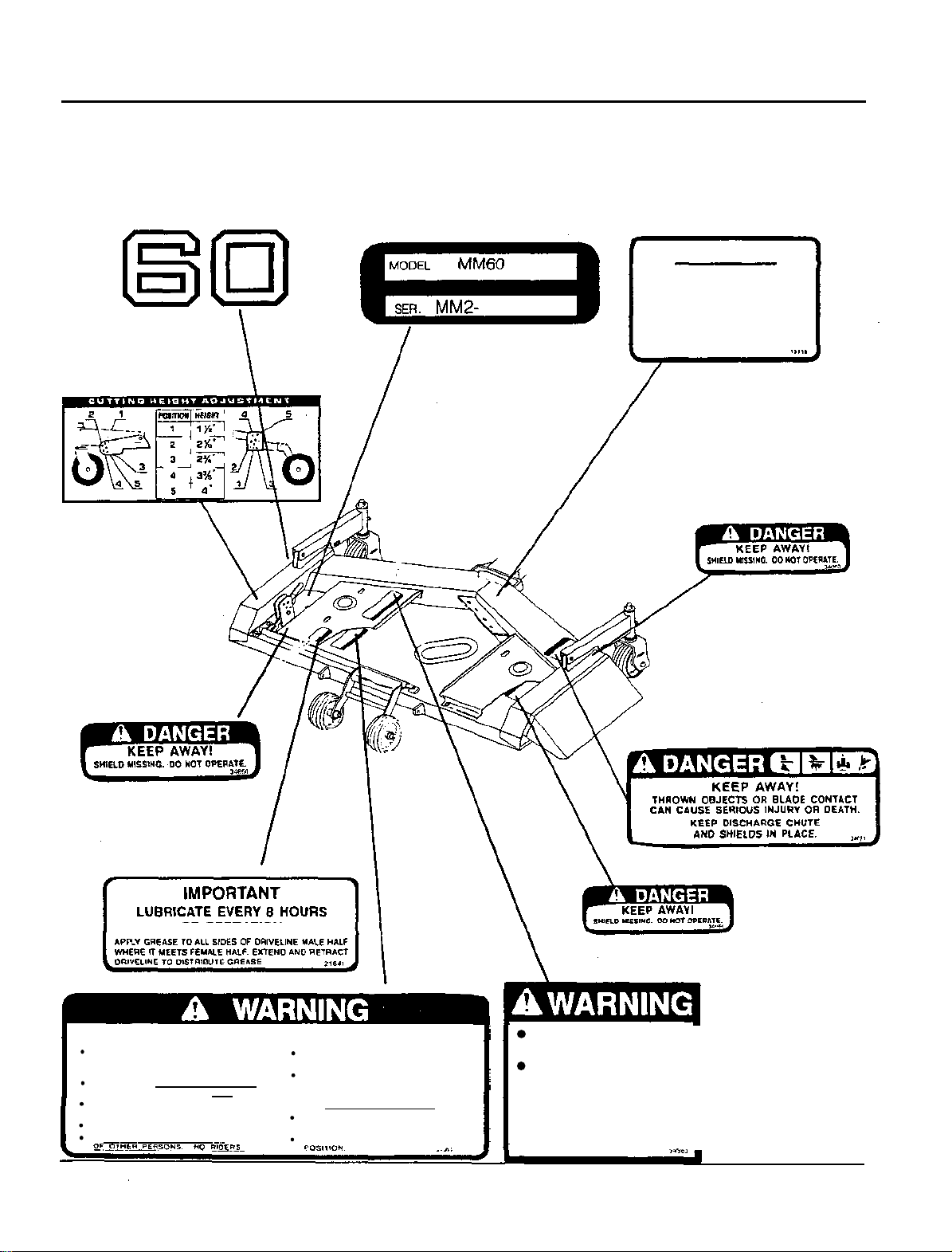
SAFETY INFORMATION
OF OTHER PERSONS. NO RIDERS.
POSITION.
Safety
Decals
Replace immediately
if
damaged.
IMPORTANT
FILL GEAR BOX
LINE
OF
HORIZONTAL SHAFT.
USE SAE
ALLOW
FLOW
THEN RECHECK.
90
TIME
THRU
GEAR LUBE.
FOR
BEARINGS.
TO
OIL
CENTER
TO
READ OPERATOR'S MANUALS & FOLLOW KNOW
ALL SAFETY PRECAUTIONS.
(CONTACT DEALER FOR MANUALS)
KEEP SHIELDS AND GUARDS IN PLACE KEY BEFORE WORKING UNDERNEATH.
KEEP CLEAR OF DRIVES AND BELTS.
LOWER IMPLEMENT, STOP ENGINE AND
REMOVE KEY BEFORE DISMOUNTING.
CLEAR MOWING AREA OF DEBRIS. DECREASE SPEED WHEN TURNING.
DO NOT OPERATE MOWER IN VICINITY DO NOT OPERATE IN TRANSPORT
OF
OPERATION
TO
AVOID SERIOUS INJURY OR DEATH!
HOW TO STOP TRACTOR AND
EQUIPMENT QUICKLY IN AN EMERGENCY.
BLOCK UP
ALLOW NO CHILDREN OR UNQUALIFIED
PERSONS TO RUN EOUIPMENT.
BE CAREFUL ON UNEVEN TERRAIN.
IMPLEMENT AND HEMOVE
...
".
PTO SPEED MUST NOT
EXCEED 2400 RPM.
LOCK DRIVELINE ON
TRACTOR PTO.
A
LOOSE
•
HIGHER PTO RPM CAN
CAUSE PERSONAL INJURY
AND EQUIPMENT FAILURE.
DRlVELlNE
OR
A
I
7

SET-UP AND ASSEMBLY
DEALER SET-UP INSTRUCTIONS
Assembly of this mower is the responsibility of the
dealer. The mower should be delivered to the
owner completely assembled, lubricated and
adjusted for normal mowing conditions.
Using these instructions, set mower up as re
-
ceived from the factory. Complete Check Lists on
Page
10
when set-up is complete.
You may install the MM60 mower with the FL6555
sub frame installed. The front loader must be
removed from the sub frame. If you also have
BH6575
Back Hoe, both the back hoe and its sub
a
frame must be removed. The adjustment of the lift
rod is different from the standard installation.
These differences are explained in the appropriate
sections. Follow these procedures to avoid
damage to deck and linkage.
The mower is shipped partially assembled.
if
Assembly will be easier
and loosely assembled before tightening hard
components are aligned
ware. Recommended torque values for hardware,
are included in the assembly instructions.
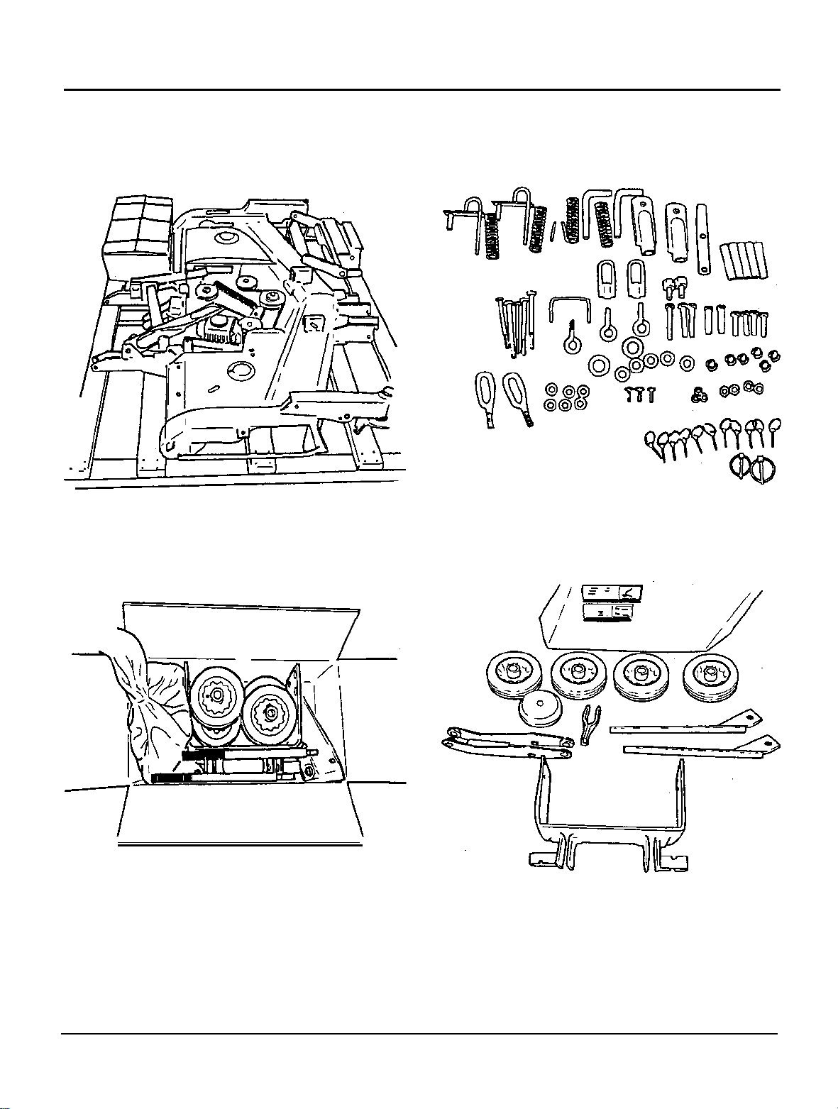
UNPACKING AND CHECKING PARTS
The mower assembly kit contains the following
parts:
Mower deck with rear linkage installed
Lift plate assembly
.
Box containing
lift
linkage and hardware
Unbolt the mower deck, and the lift plate assembly
and cut the packing straps holding down the rear
linkage and mower driie shaft. Packing list is
contained in both the crate holding the mower,
and in the parts box in the crate. Before assem
bling check for missing
or
damaged parts.
-
Select a suitable working area. Open parts boxes
and lay out parts and hardware to make location
easy. Refer to illustrations, accompanying text,
parts lists and exploded view drawings.
For
all pins, shafts and other bearing surfaces,
lubricate bearing area with a lithium based grease
#2
consistency with a MOLY (molybdenum
of
disulfide) additive before installing. The manual
will also indicate when grease is necessary.
Always wear relatively tight and
belted clothing to avoid entanglement
moving parts. Wear sturdy, rough-soled
work shoes and protective equipment for
eyes, hands, hearing and head.
Before working underneath, raise mower,
install transport lock and block mower
securely. Hydraulic system leak down and
failure of mechanical or hydraulic system
can cause equipment to drop.
Keep all persons away from operator
control area while performing adjust
ments, service or maintenance.
in
-
8
SET-UP
AND
ASSEMBLY
Mower Assembly
Parts Box
Kit in
Crate
/
Parts in Burlap Bag
Parts in Parts
Box
9

SET-UP AND ASSEMBLY
Pre-Delivery Check List
(Dealer Responsibility)
1.
Inspect the mower thoroughly after assembly to
ensure
the customer. The following check lists are a
reminder of points to inspect. Check
item as it is found satisfactory
adjustment is made.
2.
Check all bolts to be sure they are correctly
torqued.
3.
Check that all linchpins are properly installed.
4.
Lubricate all grease fittings; check to make sure
a
5.
Check that gearbox is serviced and that vent
plug is properly installed and seals are not leak
ing.
6.
Check that blades have been properly installed.
it
is
set up properly before delivering it to
off
each
or
after proper
small amount of grease comes out of seal.
Delivery Check List
(Dealer Responsibility)
1.
Check mower attitude and belt alignment.
2.
Check that mower lift is properly adjusted. (See
Assembly instructions.)
3.
Show customer how to make adjustments.
4.
Explain importance of lubrication to customer
and point out lubrication points on mower.
5.
Point out safety features, shielding and options.
6.
Present the Operator's Manual, and ask cus
tomer to become familiar with all sections.
7.
Explain to customer that when mower
-
ported on a road
should be used for adequate warning to
operators of other vehicles.
or
highway, safety devices
is
trans
-
-
SET-UP
AND
ASSEMBLY
MOUNTING MOWER
Install with the tractor on level ground.
Lock the parking brake, set the transmission lever
in "N" (Neutral) and the PTO clutch lever in the
"
OFF
"
position. Set Lift Control lever to "DOWN"
and turn Lowering Speed Control knob fully
counter-clockwise
the rear lift arms down by hand and makes assem
bly easier.
Installing Mower Lift Plate to Tractor
Remove drawbar assembly; this is bolted onto
1.
the transmission housing below the Rear PTO.
Retain bolts, nuts and spacers for installation of
lift plate assembly. Remove any dirt and debris
from bottom of transmission housing and make
sure bolt holes and screw threads are clean.
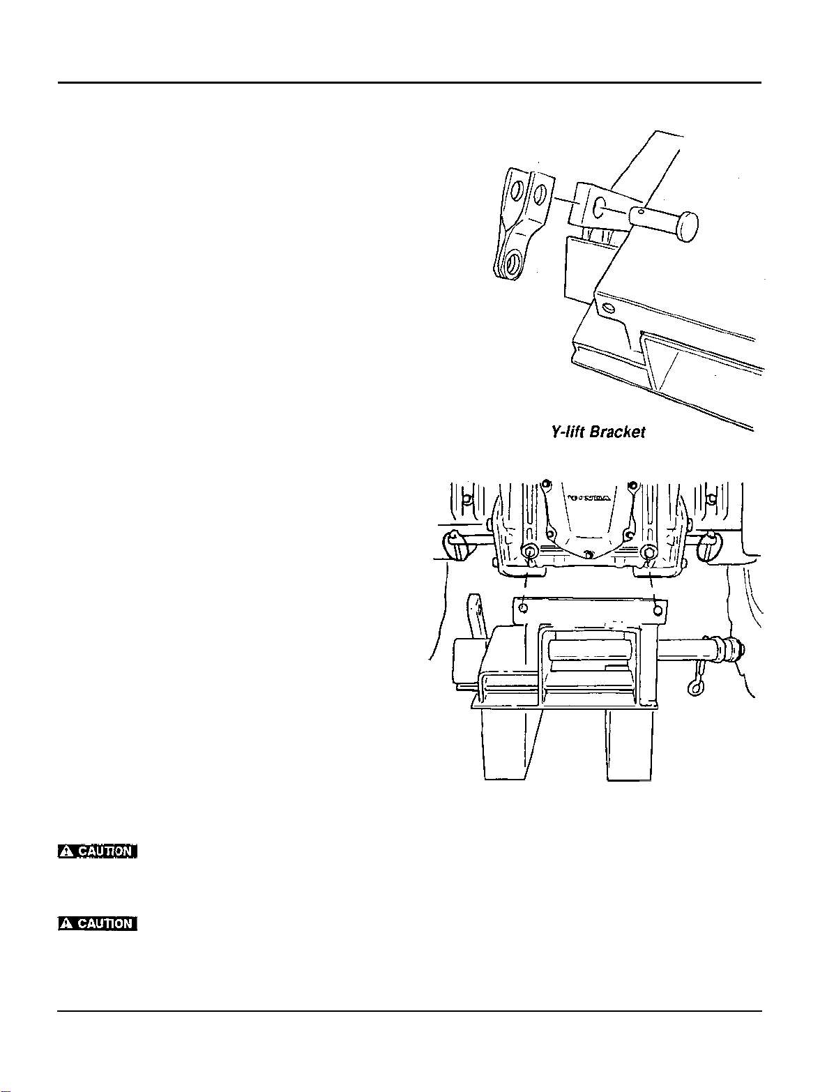
Assemble
2.
Raised flange on lift plate assembly will face rear
of tractor. Insert
faces front of tractor.
Y-lift
LIFT
SYSTEM
("FAST").
bracket to lift plate assembly.
Y-lift
This allows you to pull
bracket
so
that fork of Y
-
3.
Attach mower lift plate assembly to tractor,
passing the
transmission housing through the holes in the
plate flange. Slide on 2 spacers previously
removed and hand tighten both 26 mm flange
locknuts.
4.
Reach beneath the mower lift plate assembly
and carefully insert the four 12 mm x 32 mm
bolts through holes in
into threaded holes on bottom of transmission
housing. Housing
bolts by hand to guard against cross threading.
Tighten to
5.
Finish by tightening
on projecting studs to
your hands when installing lift link kit and
mower deck.
and hands, so keep them clear of links and
lift
arms when operating.
two
projecting stud bolts on the
lift
plate assembly and
is
made of aluminum,
7
kg-m
(50
ft-lb).
two 26
7
Wear heavy gloves to protect
Lifting system can crush fingers
mm flange locknuts
kg-m
(50
ft-lb).
so
lift
start
Mower Lift Plate
11
SET-UP
Lift Link
\
AND
ASSEMBLY
Lower Link Shaft
Y
-
bracket
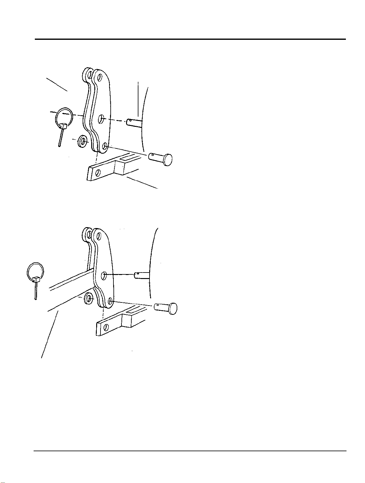
Attaching Lift Link to Lift Plate Assembly
(For Tractors Without Rear Three Point Hitch)
1.
Slide middle hole in
hand lower link shaft which comes installed on
the tractor. Install lift link
the end with
face rearward
grease to shaft. Secure with linchpin.
2.
Use a block of wood to raise left arm of lift plate
assembly about
ing the Y-bracket and the bottom hole of the
link easier. Line up hole in Y-bracket with lower
hole in lift link moving arm and lift link until they
align. Insert greased
and secure with cotter pin, passing pin from
top to bottom. Head on clevis pin faces in.
Attaching Lift Link to Lift Plate Assembly
(For Tractors With Rear Three Point Hitch)
1.
Remove left hand three point hitch lower link
from lower link shaft.
two
as
lift
link onto greased left
so
that it
holes is down. Lift link should
illustrated. Be sure to apply
150
mm (6 in) to make attach
22
mm x 76 mm clevis pin
is
vertical and
-
lift
Lower Link
2.
Mount lift link and-lower link back on lower link
shaft by lining up middle hole in lift link and hole
in lower link. Pass greased lower link shaft
through both as illustrated. Secure with linchpin,
passing pin from top to bottom.
3.
Support lift plate assembly arms on block of
wood as described above. Move lift link and
bracket
-
bracket and bottom hole in lift link line up.
Y
Insert greased
head facing in and secure with cotter pin,
passing pin from top to bottom.
on
lower lift plate assembly until hole in
22
mm x 57 mm clevis pin with
Y
-
12
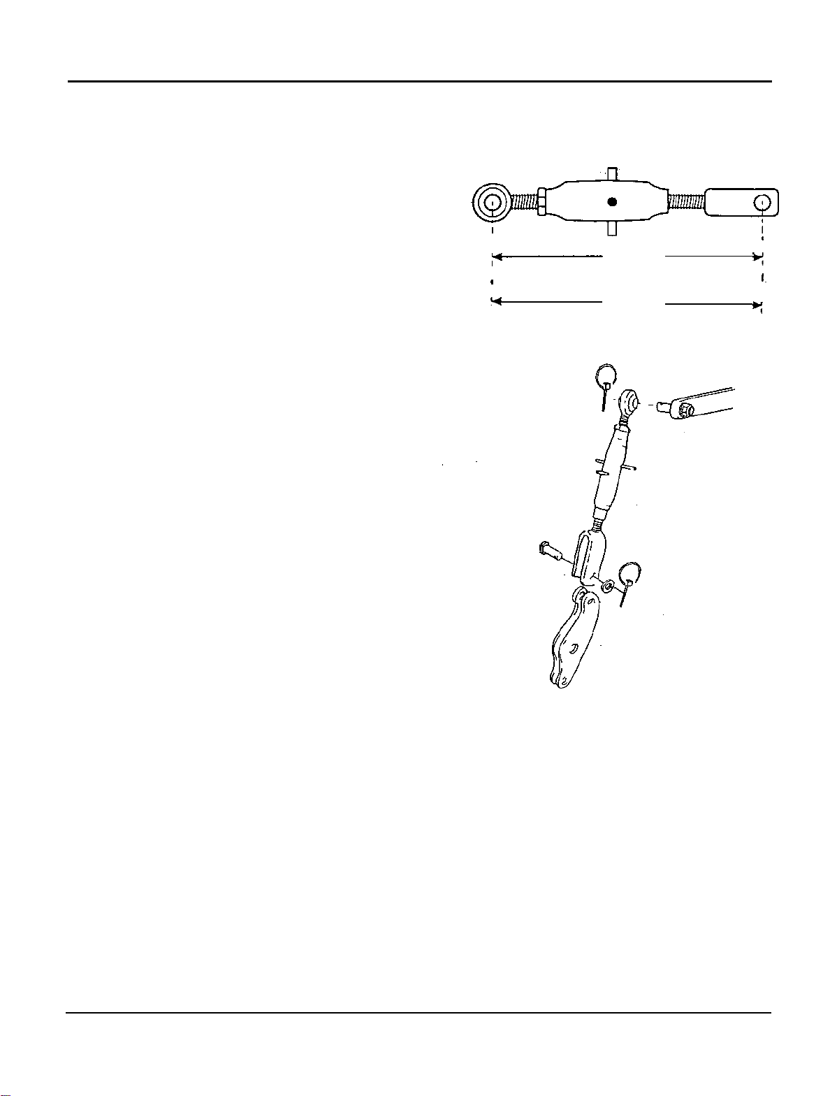
Installing Lift Rods
(For Tractors Without Rear Three Point Hitch)
1.
Adjust the lift rod to 365 mm (14.4 in) measured
from
eye to eye as illustrated. Adjustment is
of
made by turning barrel
tightening nut. Be sure that an equal length
threads shows on either end
rod, then secured by
of
,of
barrel.
SET-UP
I
I'c--------
I
I
I
Y
(with loader subframe)
AND
365 mm
14.4 in.
375
mm
14.8 in.
ASSEMBLY
I
I
y
I.
I
y
2.
Slide eye
Position clevis
of lift
rod over pin on tractor lift arm.
of lift
rod between brackets on lift
link. Note that outside leg
side
of
lift link as illustrated. Install with greased
22 x
76
mm clevis pin with head on left side as
shown. Secure both ends with
and linchpins.
of
NOTE: The eye
the lift rod is not straight. The
curve should point to the inside
when properly installed.
of
lift
22
rod goes out
mm
washers
of
the tractor
-
13
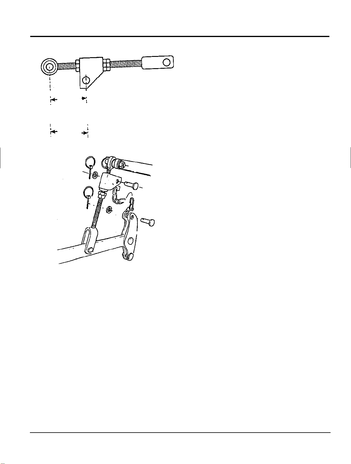
SET-UP
(with loader subframe)
AND
I
I
‘y
85
3.4
100mm
4.0 in.
ASSEMBLY
mm
7
in.
-y
Installing Lift Rods on Lower Link Lift
(For Tractors With a Rear Three Point Hitch)
1.
Replace the existing left hitch rod with the unit
I
I
provided with the mower.
2.
Loosen the locknut and the adjusting nuts and
turn them to position the bracket hole
(3.4
in) from the lift rod eye (center-to-center
measurement). The bracket must face forward.
85
mm
;
3.
Tighten the adjusting nuts and secure with the
locknut.
4.
Couple lift link chain and
16 mm lift pin. Head of pin faces inward. Secure
with washer and cotter pin. Attach upper end of
lift
link chain to bracket on
16 mm lift pin. Head of pin faces inward. Secure
with washer and linchpin.
lift
link with greased
lift
rod, with greased
14
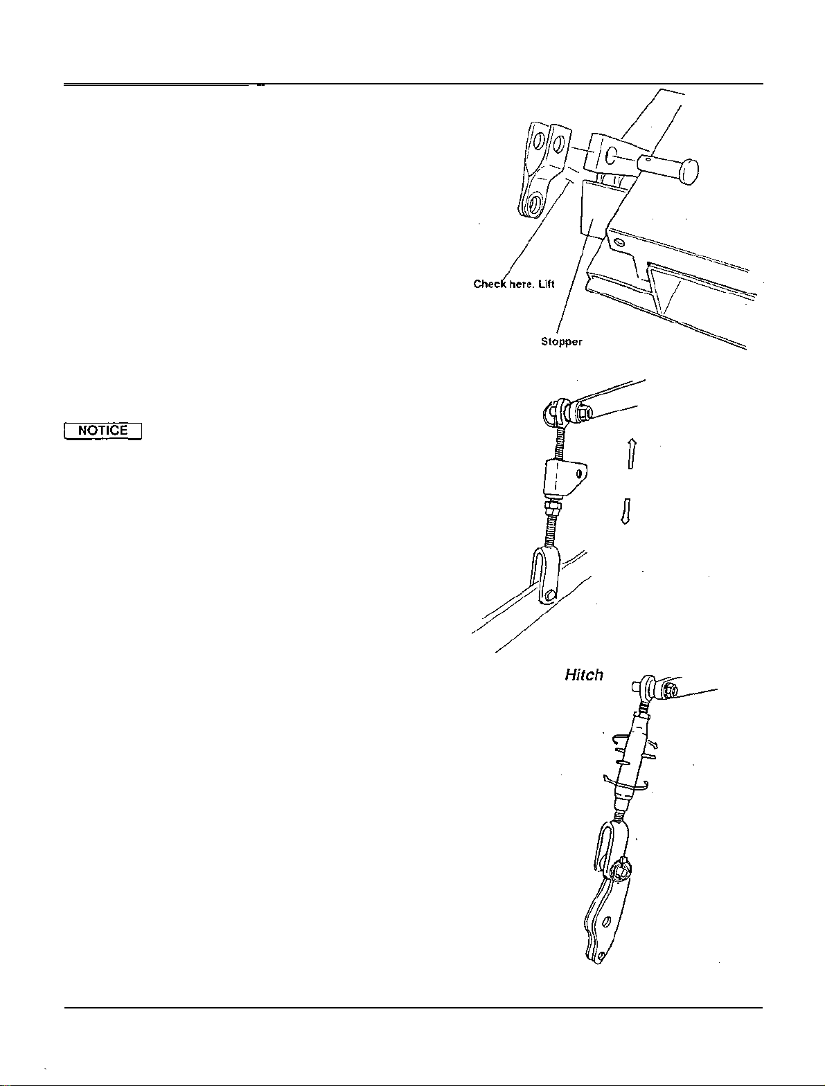
Adjusting Lift Rod
(For Tractors With and Without Rear Three
Point Hitch)
if
Follow this procedure
you do not have a loader
subframe installed.
Adjust the lift rod clearance by starting the engine,
to
"UP"
.
and shifting the Lift Control lever
Make
sure hands are clear of lift arms before starting.
Engine will not start unless operator is seated.
lift
Raise until
encountered. If resistance
Turn Lowering Speed control fully clockwise
arms up. Turn engine off. Grasp
check them for slack. They should be able
arm reaches top or until resistance is
is
encountered, stop.
to
lock
lift
rods and
to
slide
slightly on their pins. If there is no-slack in the lift
rods, increase clearance as illustrated.
Lifting system can be seriously
damaged if arm presses against stop.
SET-UP
arm should not
contact stopper
AND
ASSEMBLY
Adjusting Lift Rod
(Tractors With Rear Three Point Hitch)
To increase clearance turn bottom nut
counterclockwise
then snug top
nut.
to
loosen, slide down flange and
To
decrease clearance, slide
on
adjuster
adjuster up as shown.
Adjusting Lift Rod
(Tractors Without Rear Three Point Hitch)
Turn the barrel of the lift rod by the projecting pins
to
shorten or lengthen the rod. Move adjuster as
required. The projecting pins must point side
side (transversely) when you are finished.
don't, turn the barrel in the direction
to
increase
If
to
they
clearance until they do.
to
"
Restart engine, move Lift Selector lever
When
apply brakes and re
and fingers clear of
lift
arms reach top position, stop engine,
-
check clearance. Keep hands
lift
system when operating to
UP.
avoid injury. There should be slack in the linkage. If
there is
nuts after adjusting both types
not,
readjust as necessary. Tighten lock
of
lift
rods.
-
With
Three
Point
Without Three Point Hitch
15
SET-UP
AND
ASSEMBLY
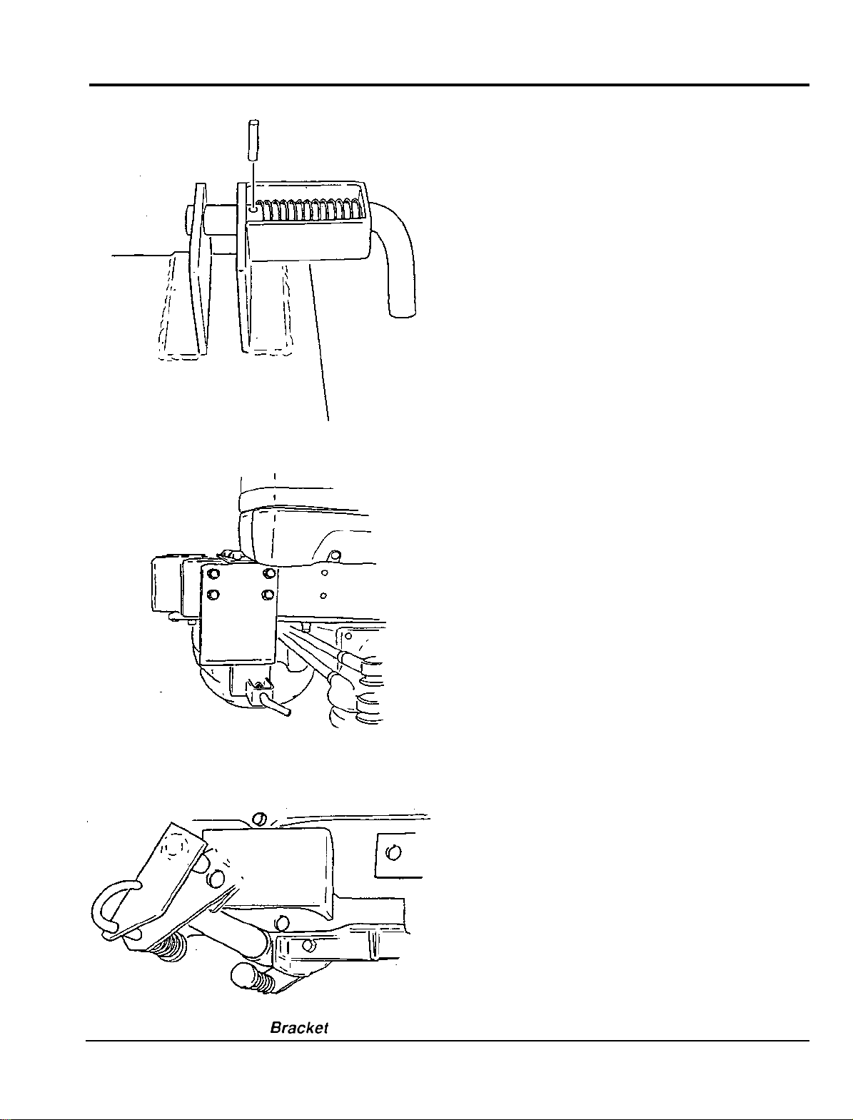
Front Link Bracket
Subassembling Front Link Brackets
Assemble by compressing the front spring and
it
inserting
front quick release pin through hole in the front
bracket and spring. Pull back spring slightly to
uncover hole in quick release pin. Use hammer
tap in spring pin until
sides of quick release pin.
NOTE: Hold back bottom of spring
clears it.
Assemble both right and left brackets.
in the front bracket slot. Pass greased
it
is equidistant from both
so
that pin
to
Front
Link Bracket
Mounting Front Link Bracket to Tractor
1.
From bottom, slip the assembled front mount
ing bracket up onto the front frame rails.
2.
Insert 8 flange bolts
to
6
kg-m
(43
ft-lb).
NOTE: With
face rearward and downward when front link
bracket is installed on the tractor.
Assembling Rear Link Bracket
Insert the greased rear quick release pin in the
mounting bracket attached to the tractor frame. It
is located beneath the tractor along the mid
as illustrated. Pass the long arm of the quick
release pin through the lower hole in the bracket
and the spring. Compress the spring and slide
washer over hole in arm. Secure with split pin,
spreading legs of split pin. Assemble both right
and left brackets.
pins correctly installed, they
12
mm x
30
mm. Tighten all
will
-
line
-
16
Rear
Link Brackef
ASSEMBLING MOWER
Checking Rear Mower Deck Links
Rear
mower links
vibration in shipping has not shaken loose the
will
come installed. Check that
two
clevis pins in brackets at rear of mower. They are
secured with linchpins.
Rear deck links should face forward, towards front
of mower, before driving tractor over mower. They
cannot be rotated forward after tractor is above
mower deck.
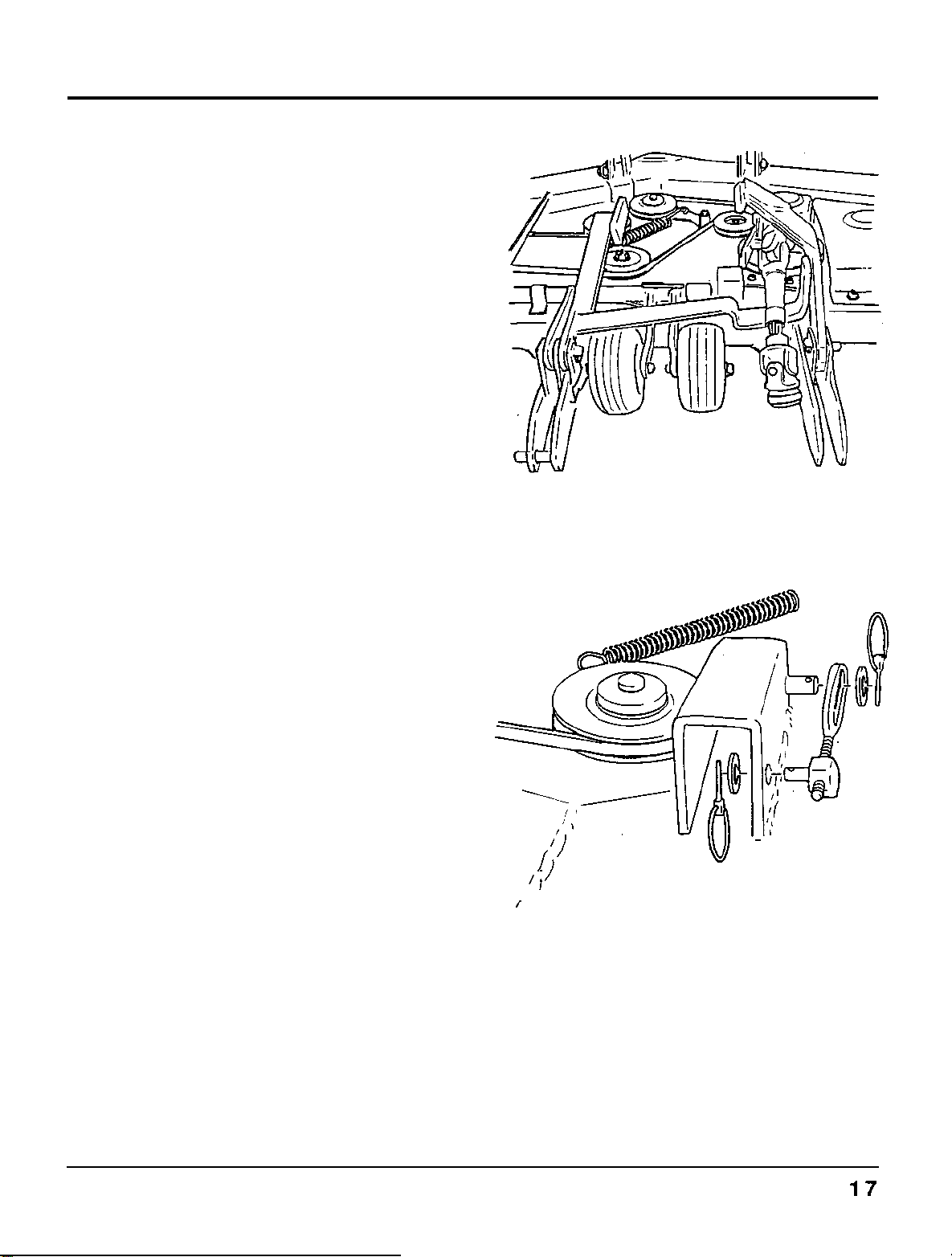
INSTALLING
MOWER
Mower driveline and U
-
joint should be on top of
stabilizer bar, not caught below it.
Be sure the left rear deck link is installed with the
side marked "UP" facing top.
Installing
Deck
Hooks
Right and left mower deck hooks are installed on
brackets in the front center of the deck. See
position as indicated. Screw mower deck hook
into adjustable pin. Insert pin into slot in bracket.
Secure with washer and linchpin.
Rear Mower Deck Links
/
f
I'
Deck Hooks
 Loading...