

Page 1
Dealer Instructions
for
SETUP
and
PRE-DELIVERY SERVICE
HS520A • HS520AS
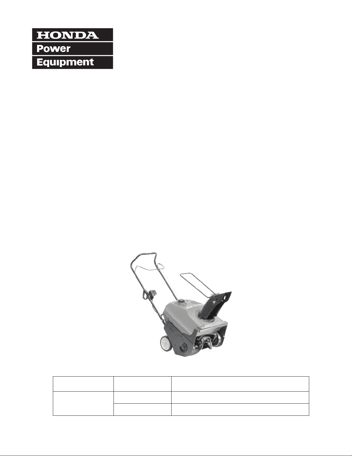
SNOWTHROWER
MODEL TYPE FRAME SERIAL NUMBER RANGE
HS520 A 6017207 to subsequent
AS 6100001 to subsequent
© 1999–2005 American Honda Motor Co., Inc.—All Rights Reserved TO020 PPD53092-D (August 2005) 1 of 10
Page 2

HS520A • HS520AS SNOWTHROWERS
IMPORTANCE OF PROPER SET-UP AND PRE-DELIVERY SERVICE
FOR YOUR CUSTOMER’S SAFETY
Proper set-up and pre-delivery service are essential
to the customer’s safety and the reliability of the
snowthrower. Any error or oversight made during
assembly and servicing of a snowthrower can result
in faulty operation, damage to the snowthrower, or
injury to others.
FOR YOUR SAFETY
Some of the most important general safety
precautions are given below. However, we cannot
warn you of every conceivable hazard that can arise
in performing set-up and pre-delivery service. Only
you can decide whether or not you should perform a
given task.
WARNING
Improper set-up or pre-delivery service can
create an unsafe condition that can cause
your customer or others to be seriously hurt
or killed.
Follow the procedures and precautions in
this manual and other service materials
carefully.
WARNING
Failure to properly follow instructions and
precautions can cause you to be seriously
hurt or killed.
Follow the procedures and precautions in
this manual carefully.
IMPORTANT SAFETY PRECAUTIONS
Make sure you have a clear understanding of all basic shop safety practices and that you are wearing
appropriate clothing and safety equipment. When performing set-up and pre-delivery service, be
especially careful of the following:
• Read all of the instructions before you begin, and make sure you have the tools, the replacement or
repair parts, and the skills required to perform the tasks safely and completely.
• Protect your eyes by using proper safety glasses, goggles, or face shields any time you hammer, drill,
grind, or work around pressurized air or liquids and springs or other stored-energy components. If
there is any doubt, put on eye protection.
• Use protective wear when necessary, for example, gloves or safety shoes. Handling hot or sharp parts
can cause severe burns or cuts. Before you grab something that looks like it can hurt you, stop and put
on gloves.
Make sure the engine is off before you begin any servicing procedures, unless the instruction tells you
to do otherwise. This will help eliminate several potential hazards:
• Carbon monoxide poisoning from engine exhaust. Be sure there is adequate ventilation whenever you
run the engine.
• Burns from hot parts. Let the engine and exhaust system cool before working in those areas.
• Injury from moving parts. If the instruction tells you to run the engine, be sure your hands, fingers, and
clothing are out of the way.
Gasoline vapors are explosive. To reduce the possibility of a fire or explosion, be careful when working
around gasoline or batteries.
• Use only a nonflammable solvent, not gasoline, to clean parts.
• Never drain or store gasoline in an open container.
• Keep all cigarettes, sparks, and flames away from all fuel-related parts.
2 of 10
Page 3
HS520A • HS520AS SNOWTHROWERS
Set-up and pre-delivery service must be performed by an authorized Honda snowthrower dealer. These
instructions are provided for dealer use.
FOLLOW THESE INSTRUCTIONS CAREFULLY
Proper set-up and pre-delivery service are essential for safe, reliable operation. Your customer expects the
Honda snowthrower to be correctly assembled, adjusted, and ready for use; test the snowthrower to be
sure that it functions properly. Fill out the Power Equipment Pre-Delivery Check List (TO056) and give it to
the customer.
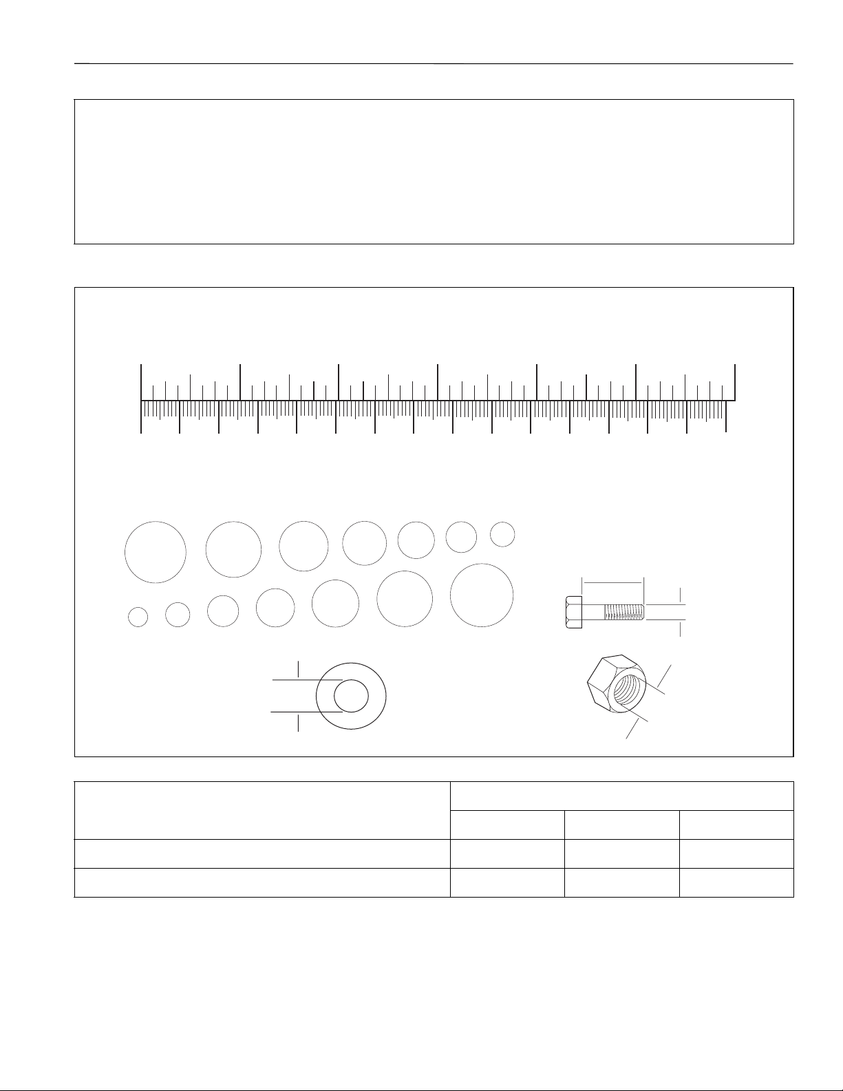
How to measure hardware and components:
INCHES
0
123
4
56
0 10 20 30 40 50 60 70 80 90 100 110 120 130 140 150
MILLIMETERS
5/8 in 9/16 in 1/2 in 7/16 in 3/8 in 5/16 in 1/4 in
5mm 6mm
WASHERS ARE SPECIFIED
BY INSIDE DIAMETER
8mm
NUT AND BOLT DIAMETER
10 mm
12 mm
14 mm
16 mm
NUTS ARE SPECIFIED
BY INSIDE DIAMETER
(AT THREAD DEPTH)
STANDARD TORQUE VALUES
•m kg-m ft-lb
N
DIAMETERLENGTH
INSIDE
DIAMETER
6 mm flange bolts and nuts 11 1.1 8.0
8 mm flange bolts and nuts 22 2.2 16.0
Torque values for special hardware will be called out during the procedure.
3 of 10
Page 4
HS520A • HS520AS SNOWTHROWERS
UNCRATING
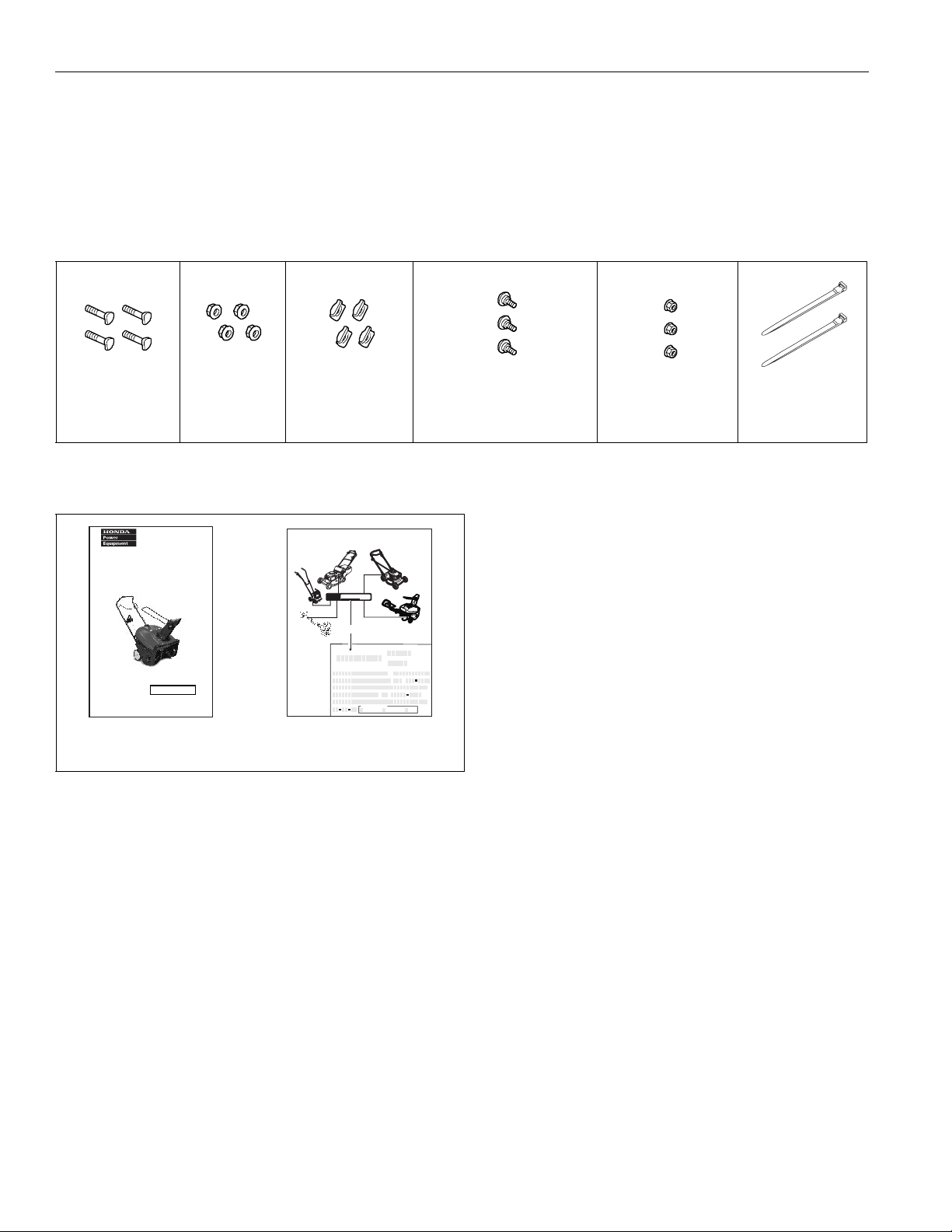
1. Open the carton and remove the handlebar assembly, discharge chute assembly, snowthrower,
and parts bag. Verify the contents of the parts bag with the table below.
2. Remove the starter bracket (HS520A) or starter box bracket (HS520AS) from the lower handlebar tube.
Save the curved-head bolt and flange nut for later installation of the starter bracket or starter box bracket.
PARTS BAG
Curved head bolt,
8 x 40 mm (4)
PN 90109-VA4-000
Flange nut,
8 mm (4)
PN 94050-08000
Curved washer,
9 mm (4)
PN 90501-898-000
Phillips head shoulder screw,
6 x 12 mm (3)
PN 90112-V10-000
Nylock flange nut,
6 mm (3)
PN 90303-V10-000
Cable tie (2)
(HS520AS only)
PN 32901-VB5-A00
HANG BAG
®
Owner's Manual
Snowthrower
HS520A HS520AS•
See page 39 for instructions on
©1999–2005 AmericanHonda MotorCo., Inc.—AllRights Reserved
setting up your Snowthrower.
Owner’s manual
PN 31V10610
S A L E S R E G IS T R ATIO N
PLEASE COMPLETE & MAIL
HondaHarmony Mowers
Lookon themower deck,jus tinfront ofthe
discharge guarddoor spring.
Honda
Mini-Tiller
MODEL:
SERIALNO:
XXXXXXXX
XXXX-XXXXXXX
Printthes erial
numberher e.
Serialnumber
Owner'sLast Name
CompanyName
Address
City
Emailaddress
Dateof S ale
MONTH
Lookon thetop of
theba ckf ender.
Honda
Hand-HeldProducts
Lookontheshaft
between the twogr ips.
DearHonda C ustomer,
Thank youfor choosing
Honda.
Pleasetake a momentto
completeand mailthis
Postage-paid
sales regis trationc ardto
ensureyoureceive
information ofproduc t
andserviceupdates.
Failure toreturn this card
does notdiminis hthe purchaser'swarrantyrights.
PWL51844G(2003.02)
(commercial/rentalusers)
Application
Commercial Non-c ommerc ial R ental
(professionaluse)
YEARDAY
Honda
HarmonyII Mowers
Lookontherightrearsection
ofthe mowerdeck.
HondaHa rmony Snowthrowers
Lookbetween thewheels onthe lowerframe .
*Dealer S torenumber
*DealerStoreZIPcode
FirstName
Telephone
()
State ZIPCode
(checkone)
(private,homeowneruse) (for-hireuse)
Sales Registration
*Ifavailable
For concealed damage, file a Concealed Damage warranty claim using the Interactive Network (),
path Service>Warranty Claim.
For parts left out by the factory, file a Normal warranty claim for missing parts using the Interactive
Network (), path Service>Warranty Claim.
If the Sales Registration form is missing or damaged, you can:
• Register the product online using the Interactive Network (), path Sales>Sales Registration.
• Use the pre-printed forms sent with the product invoice.
• Contact PE Sales Registration (800)354-6632, option 7, for blank registration forms.
4 of 10
Page 5
HS520A • HS520AS SNOWTHROWERS
ASSEMBLY
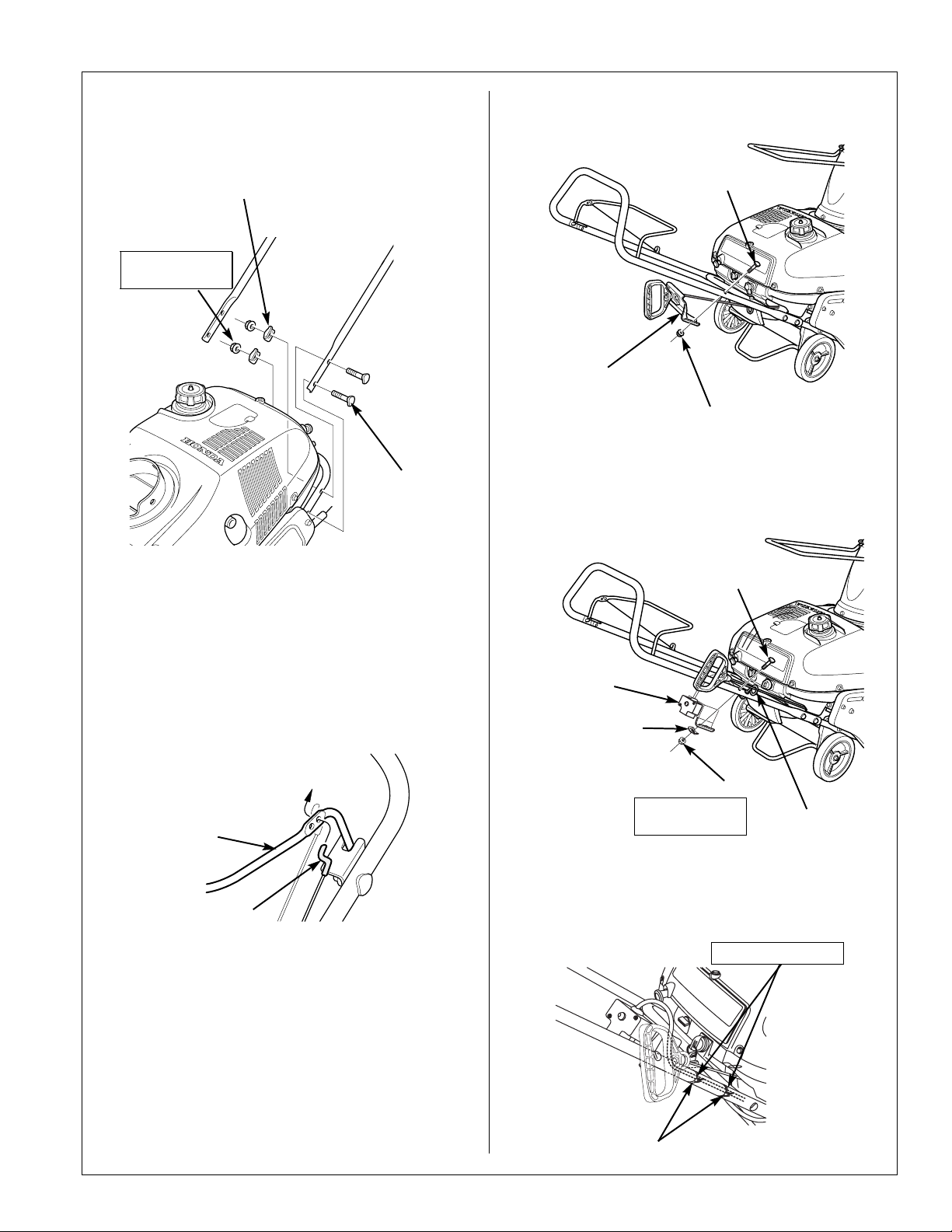
1. Install the handlebar with the hardware shown.
Tighten the flange nuts securely.
9 mm CURVED
WASHER (4)
8 mm FLANGE
NUT (4)
TORQUE:
22 N
•m (16 ft-lb)
8 x 40 mm CURVED
HEAD BOLT (4)
3. HS520A: Use the hardware removed in step 2
on page 4 of 10 to attach the starter bracket.
8 mm CURVED
HEAD BOLT
STARTER
BRACKET
8 mm FLANGE NUT
4. HS520AS: Use the hardware removed in step
2 on page 4 of 10 to attach the starter box
bracket, then install the starter rope into the
handlebar rope guide.
2. Put the clutch cable end through the auger
clutch lever upper hole (closest to the bend) as
shown.
AUGER
CLUTCH
LEVER
CABLE
END
8 mm CURVED
HEAD BOLT
STARTER BOX
BRACKET
9 mm CURVED
WASHER
8 mm FLANGE NUT (4)
TORQUE:
22 N
•m (16 ft-lb)
ROPE GUIDE
Install two cable ties around the handlebar and
starter cable, then trim off the excess material
leaving about 10 mm (3/8 in).
CABLE TIE (2)
Trim to 10 mm (3/8 in)
EQUALLY
SPACED
5 of 10
Page 6
HS520A • HS520AS SNOWTHROWERS
0W-30
5W-30
SAE
5W-30
A
P
I
S
E
R
V
I
C
E
S
J
E
N
E
R
G
Y
C
O
N
S
E
R
V
I
N
G
I
I
AMBIENT TEMPERATURE
-30
-20
-10
010
30
20
200-20 40 60 80
o
40 C
o
100 F
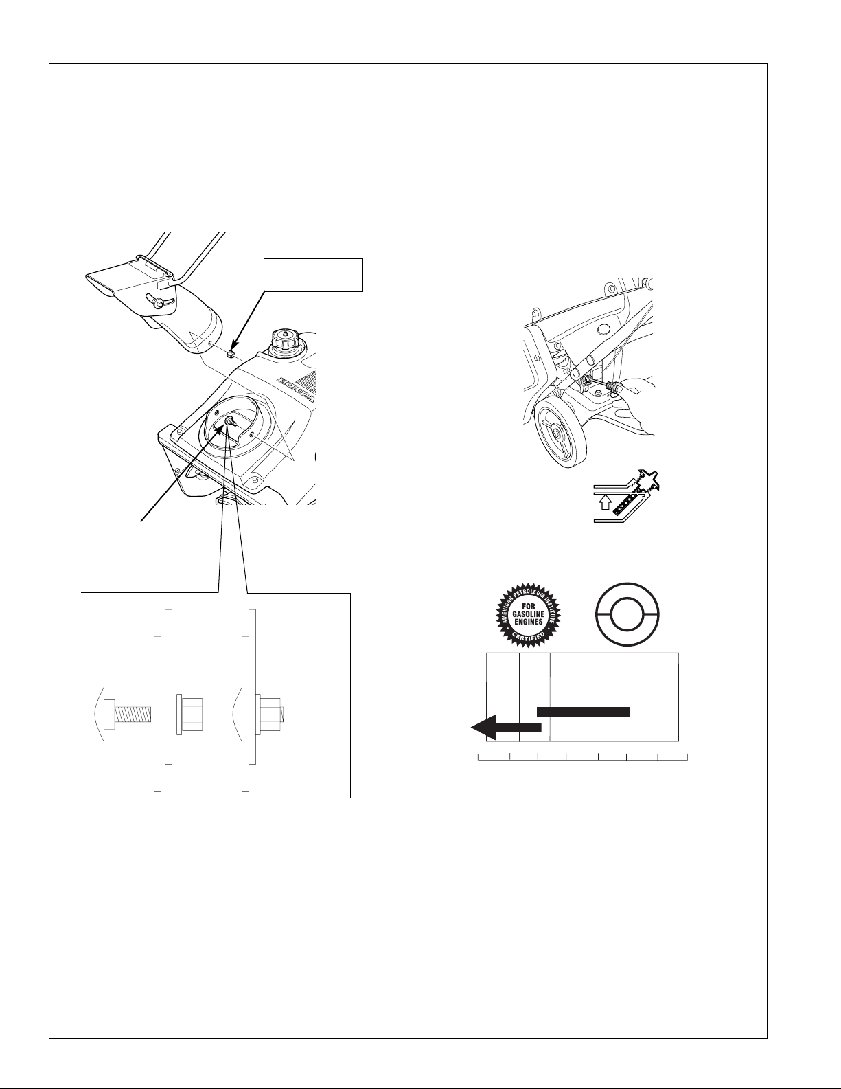
5. Install the discharge chute using the three
6 mm Phillips head screws and 6 mm nylock
flange nuts. Make sure the screws go on the
inside and the nuts on the outside.
6 mm NYLOCK
FLANGE NUT (3)
TORQUE:
•m (7 ft-lb)
10 N
PRE-DELIVERY SERVICE INSPECTION
Engine
The snowthrower is shipped WITHOUT ENGINE
OIL. A bottle of oil is included with the
snowthrower.
1. Remove the oil filler cap/dipstick and add the
entire contents of the oil bottle into the oil filler
opening to bring the oil level up to the upper
limit. Do not overfill.
UPPER LIMIT
PHILLIPS HEAD
SHOULDER SCREW (3)
INSIDE
OUTSIDE
6. Lift the spark plug door and attach the spark
plug wire to the spark plug.
7. Remove any packing material from the side of
the snowthrower.
Use SAE 5W-30 or 0W-30 API SJ or later engine
oil only.
2. Fill the fuel tank with fresh, 86 octane unleaded
gasoline.
6 of 10
Page 7
HS520A • HS520AS SNOWTHROWERS
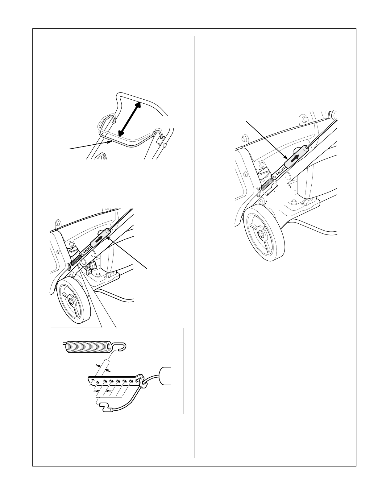
Auger Clutch Lever Freeplay
Pull up the auger clutch lever until resistance is
felt, then measure the distance shown.
ENGAGEMENT TRAVEL:
7-1/2 ~ 8 in (190 ~ 205 mm)
7-1/2 ~ 8 in
(190 ~ 205 mm)
AUGER
CLUTCH LEVER
If adjustment is necessary:
1. Pull the spring cover up to expose the spring.
2. Change the cable or spring position on the
metal plate to change the lever travel.
Belt Tension
1. Pull the spring cover up to expose the spring.
2. Have a helper engage the auger clutch lever.
3. Measure the spring coil length as shown.
SPRING COIL LENGTH: 3 inches (78 mm)
SPRING
COVER
)
n
i
3
78 mm
(
SPRING
COVER
SPRING
1/4 in (6 mm)
3/8 in (10 mm)
Moving the spring makes a 1/4 inch (6 mm)
travel change and moving the cable one hole
makes a 3/8 inch (10 mm) travel change.
4. If the length of the spring coil is less than
3 inches, move the spring and/or the cable
connected to the metal plate so the stretched
spring is at least 3 inches long.
7 of 10
Page 8
HS520A • HS520AS SNOWTHROWERS
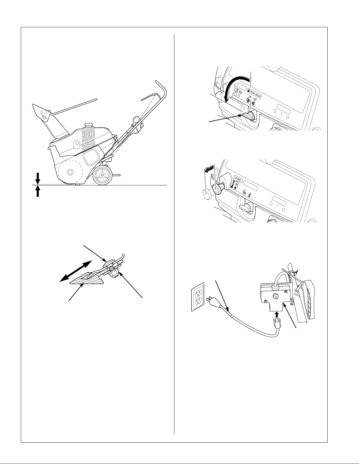
Auger Paddle
Measure the distance between the ground and
the lowest point on the auger rubber paddle.
PADDLE GROUND CLEARANCE:
1/16 ~ 1/8 inch (1 ~ 3 mm)
1/16 ~ 1/8 inch (1 ~ 3 mm)
If adjustment is necessary:
1. Loosen but do not remove the three self-locking
nuts on the scraper blade.
CARRIAGE BOLT (3)
OPERATIONAL TESTS
1. Make sure the spark plug cap is connected.
2. Turn the fuel valve to the ON position.
ON
FUEL
VALVE
3. If the engine is cold, pull the choke knob out to
the CLOSED position.
CLOSED
4. Start the engine:
Electric Starting (AS model only):
a. Connect an extension cord to the starter box
first, then to a 120 volt ac outlet.
SCRAPER
SELF-LOCKING
NUT (3)
2. Move the scraper blade up or down slightly as
needed and tighten the self-locking nuts.
Recheck the clearance.
3. Repeat the procedure as needed to get the
necessary clearance.
Other Items
With the spark plug cap disconnected, check the
security of all nuts, bolts and other fasteners.
Tighten if necessary.
OUTDOOR EXTENSION CORD
STARTER BOX
Use an outdoor extension cord with a current
rating of at least 15 amps. Do not connect and
disconnect the extension cord with wet hands.
Do not use in the rain.
Be sure to hold the plug when disconnecting
the power cord from the electrical outlet or
starter box. Do not disconnect by pulling on the
power cord.
8 of 10
Page 9
HS520A • HS520AS SNOWTHROWERS
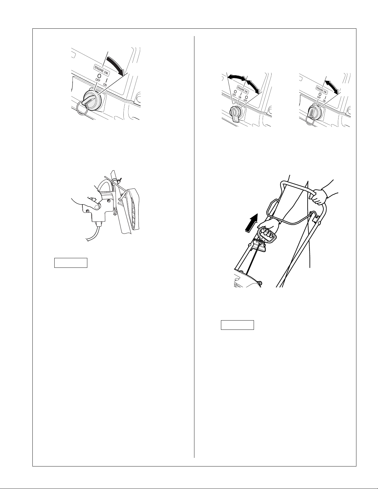
b. Turn the engine switch to the ON position.
ON
c. Push the starter button until the engine
starts. After the engine starts, disconnect the
extension cord from the electrical 120 volt ac
outlet, and then from the starter box.
Manual Starting
a. Turn the engine switch to the ON position.
ON
HS520A
HS520AS
b. Pull the starter grip slowly until resistance is
felt, then pull briskly.
ON
NOTICE
To prevent starter motor damage, do not
operate the starter for more than 15
seconds at a time. If the engine fails to
start, release the starter button and allow
the starter motor to cool for 10 minutes
before operating it again.
d. If the choke knob was used to start the
engine, gradually return it to the OPEN
position as the engine warms up. Let the
engine run for several minutes.
c. Return the starter grip gently.
NOTICE
Do not allow the starter grip to snap back.
Return it gently to prevent damage.
Do not pull the starter grip while the engine
is running. The starter could be damaged.
d. If the choke knob was used to start the
engine, gradually return it to the OPEN
position as the engine warms up. Let the
engine run for several minutes.
9 of 10
Page 10
HS520A • HS520AS SNOWTHROWERS
POWER EQUIPMENT PRE-DELIVERY CHECKLIST
THEFOLLOWING PRE-DELIVERY CHECKLIST IS DESIGNEDFOR GENERAL APPLICATION.
THEREARE INDIVIDUAL EXCEPTIONS TO THISLIST. REFER TOTHE APPROPRIATE SET-UP
INSTRUCTIONSAND SHOP MANUALS FOR DETAILEDPROCEDURES AND SPECIFICATIONS.
WHITECOPY–Dealer YELLOWCOPY–Customer TO056 OTR50671-C(2005.07)
ENGINEOIL - Fill to thecorrect level with recommended oil
FUELTANK - Drain, inspectand fill. Check for leaks
CARBURETORFLOAT CHAMBER - Drainold gasoline
COOLANT- Check coolant level. Fillif necessary with a 50/50solution
ofdistilled water and ethylene glycolantifreeze
BATTERY- Check the electrolytelevel is correct and thebattery is fully
charged
TRANSMISSIONFLUID LEVEL - Check fluidlevel and check for leaks
CLUTCHLEVER FREE PLAY -Adjust if necessary
BLADECONTROL LEVER - Adjust ifnecessary
SHIFTLEVER FREE PLAY -Check free play and adjustif necessary
AUGERCLUTCH LEVER - Check freeplay and adjust if necessary
MOWERHEIGHT ADJUSTMENT LEVERS - Checkoperation and set
alladjustment levers to the sameheight
TIREPRESURE - Check for propertire pressure
BLADEBOLTS - Check bladebolts for proper torque
ATTACHMENTINSTALLATION
ALLNUTS, BOLTS AND OTHERFASTENERS - Check securityand
tightenif necessary
PRE-DELIVERYINSPECTION PERFORMED BY:
PRINTNAME:_____________________________ DATE:______________
CHECKTHROTTLE OPERATION
CHECKIDLE AND MAXIMUM ENGINE SPEED
CHECKGOVERNOR OPERATION
CHECKDRIVE BRAKE OPERATION
CHECKDRIVE CLUTCH OPERATION
CHECKATTACHMENT OPERATION
CHECKMOWER CONTROL/AUGER CLUTCH OPERATION
CHECKSAFETY INTERLOCK SYSTEM OPERATION
CHECKSHIFT LEVER OPERATION
CHECKHEADLIGHT OPERATION
UPONCOMPLETION OF TEST, CHECKFOR FUEL OR OIL LEAKS
OPERATIONALTEST PERFORMED BY:
PRINTNAME:____________________________ DATE:________________
CHECKMAXIMUM NO-LOAD ENGINE SPEED (RPM______________)
CHECKAUTO-THROTTLE/ECO-THROTTLE™ OPERATION
PERFORMLOAD BANK TEST
CHECKOUTPUT FROM EACH RECEPTACLE
GENERATOROPERATIONAL TEST PERFORMEDBY:
PRINTNAME:___________________________________ DATE:__________
REVIEWPRE-DELIVERY CHECKLIST
REVIEWOWNER’S MANUAL
EXPLAINOPERATION
REVIEWWARRANTY COVERAGE AND POLICIES
EXPLAINMAINTENANCE INTERVALS
EXPLAINSERVICE AVAILABILITY
EXPLAINSAFETY PRECAUTIONS
FILLOUT OWNER’S I.D. CARD ANDSALES REGISTRATION
TOOLKIT (IF APPLICABLE)
IHAVE RECEIVED THE FOLLOWING:
OWNER’SMANUAL
DISTRIBUTOR’SLIMITED WARRANTY
OWNER’SI.D. CARD
ATTACHMENTOPERATOR’S MANUAL(S)
PRE-DELIVERYCHECKLIST (YELLOW COPY)
Theoperation of this unit wasreviewed with me by arepresentative of the
dealership.I have reviewed and understandthe warranty policy. Ihave visually
inspectedthe unit and found nodefects.
PRE-DELIVERY INSPECTION
OPERATIONAL TEST
DEALER
NAME
MODEL
NUMBER
FRAME
NUMBER
DEALER
NUMBER
ENGINE
NUMBER
GENERATOROPERATIONAL TEST
RATEDLOAD (AC)
VOLTS AMPS FREQUENCY
DCBATTERY CHARGE SYSTEM
DCVOLTS
DELIVERY CHECKLIST
CUSTOMER DELIVERY
CUSTOMER
NAME
ADDRESS
CITY STATE
ZIP
CODE
PHONENUMBER ( )
SIGN ATURE DATE
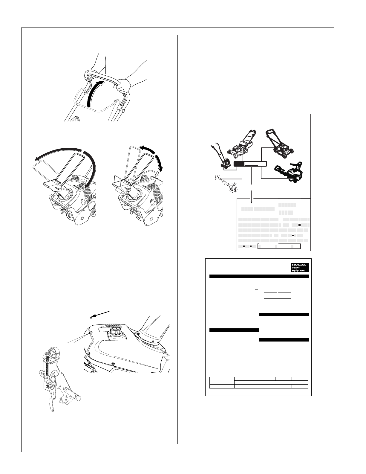
5. Verify the auger engages when you pull back
on the auger clutch lever.
6. Operate the chute guide and make sure it
moves smoothly.
7. Start the engine and allow it to warm up to
normal operating temperature. Check the
engine rpm with the auger disengaged.
MAXIMUM ENGINE SPEED:
3,700 ~ 3,850 rpm
If adjustment is necessary, remove the rubber
plug and turn the governor adjustment screw
as needed to achieve the specified rpm.
10.Turn the fuel valve to the OFF position. Start
the engine and allow the carburetor to run out
of gas.
11.Upon completion of tests, check for fuel and oil
leaks. Repair if necessary.
12.Fill out the top section of the Sales Registration
and the applicable sections of the Power
Equipment Pre-Delivery Check List. Put both
documents in the documentation hang bag.
S A L E S R E GIS TR ATIO N
PLEASE COMPLETE & MAIL
Honda Harmony Mowers
Look on the mower deck, just in frontof the
discha rge guard door spring.
Honda
Mini-Tiller
Look on the topof
the ba ck fe nder.
Honda
Hand-HeldP roducts
Lookontheshaft
betwe en the tw o grips .
Dear H onda Customer,
Thank youfor c hoosing
Honda.
Please take a momentto
complete and mailthis
Postage-paid
sa les registration c ard to
ensureyou receive
information o f product
andserviceupdates.
Failure toreturn this card
does notdiminis h the pu rchaser's warrantyrights.
PWL51844G (2003.02)
MODEL :
SERIALNO:
Printtheserial
Serial number
Owner'sLas t Name
CompanyName
Address
City
Emailaddress
Date of S a le
MONTH
XXXX XXXX
XXXX-XXXXXXX
number here.
(commercial/rentalusers)
YEARDAY
Application
Commercial Non-commercial Rental
(professionaluse)
Honda
Harmony II Mowers
Lookontherightrearsection
ofthe mower dec k.
Honda Harmony Snowthrowers
Look between the wheels on the lower frame.
*Dealer S tore number
*DealerStoreZIP code
FirstName
Telephone
()
State ZIPCode
(checkone)
(private,homeowner use) (for-hire use)
*Ifav a ilable
GOVERNOR
ADJUSTMENT
SCREW
8. Verify the auger stops turning when the auger
clutch lever is released.
9. Verify the engine stops when the engine switch
is moved to the OFF position.
10 of 10
RUBBER PLUG
13. Remember to complete the Sales Registration
and the Pre-Delivery Check List when the
snowthrower is delivered to the customer.
Page 11

Page 12

 Loading...