

Honda goldwing gl1200 line Installation Manual
HONDA-LINE,R
INSTRUCTION
) AUDIO
SYSTEM
FOR
MANUAL
GL1200
r
HONDALINE~
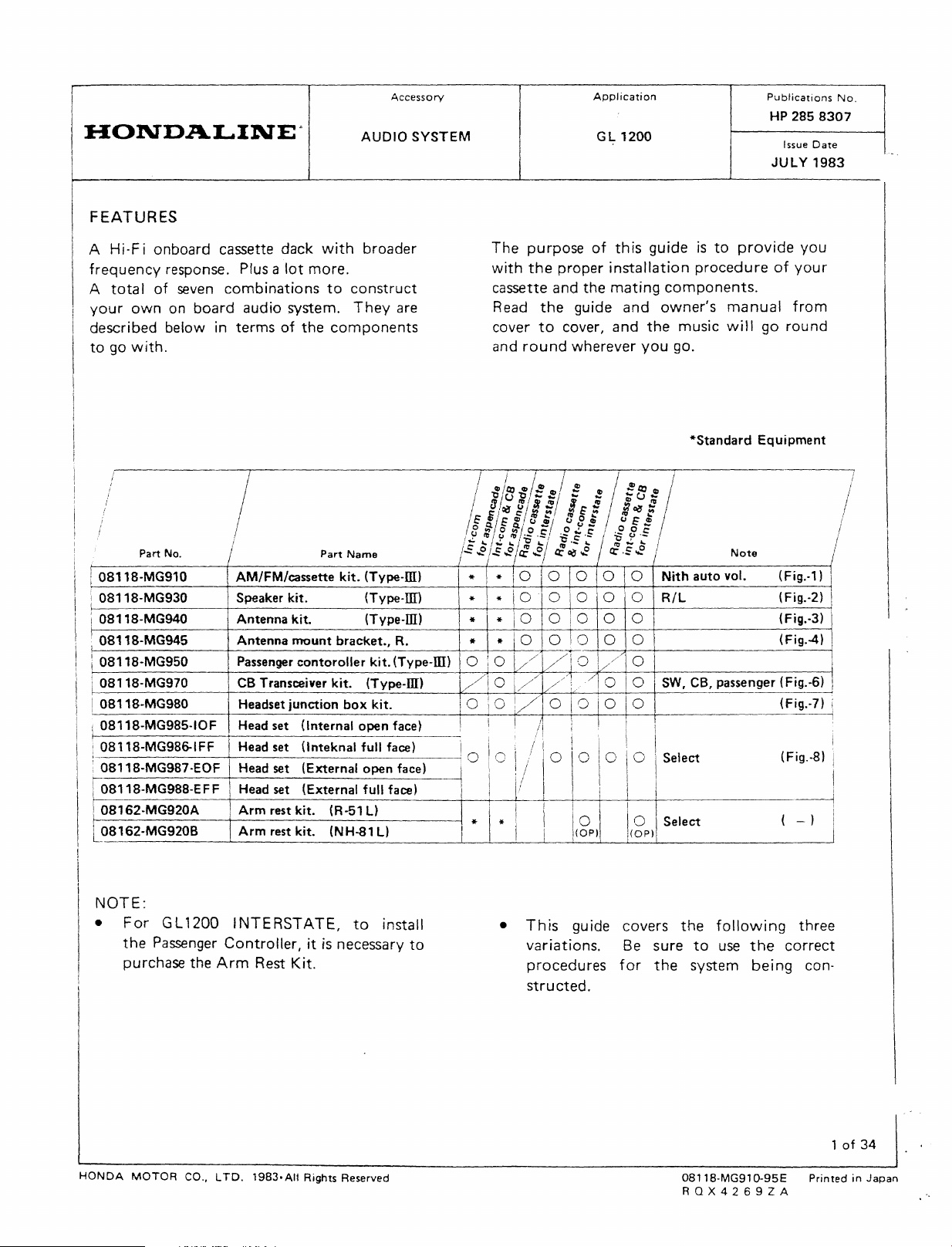
FEATURES
A Hi-F i
frequency
A
your
described
to
tota
go
I
own
with.
onboard
response.
of
seven
on
below in
cassette
Plus a
combinations
board
termsofthe
audio
dack
lot
more.
system.
AUDIO
with
broader
to
construct
They
components
Accessory
SYSTEM
are
The
purpose
with
the
cassette
Read
cover
and
round
and
the
to
Application
of
proper
the
guide
cover,
wherever
GL
1200
this
installation
mating
and
and
the
you
guideisto
procedure
components.
owner's
music
go.
Publications
provide
manual
will
go
HP
Issue
JULY
of
round
No.
2858307
Date
1983
you
your
from
*Standard
Equipment
)
I
/
I
auto
Note
vol.
(Fig.-1)
(Fig.-2)
(Fig.·3)
(Fig.4)
(Fig.-S)
(Fig.-7)
(Fig.-S)
Part
No.
08118-MG910 AM/FM/cassette
08118-MG930 Speaker kit. (Type-ffi) I * * \ 0 0 0 0 0
08118-MG940
08118-MG945
08118-MG950 Passenger
08118-MG970
! OB118-MG980 Headset
i 08118-MG985-IOF
f-----------j--------------
Antenna
Antenna
CB
Transceiver kit. (Type-ill)
Head
set (Internal
:_O_8_1_1_8_~_G_9_8&_IF_F_~H-e-~-~-t-(-ln-t-ek-n-a-l-fu_1_I_fu_~_)_~!O
i08118-MG987-EOF Head set
r08118-MG988-EFF
08162-MG920A Arm rest kit. (R-51
'-~_8_1_6_2_-M_G_9_2_0_B
Head set (External full face)
_
___'__A_rm_re_s_t_k_it_.
Part
kit.
mount
contoroller
junction
(External
_(N_H_-8_'_L_l
Name
kit.
(Type-ml * *
(Type-ill) * \ *
bracket.,
box
R. * *
kit.
(Type-Ill) 0 I 0
kit.
open
face) !
open
face) ! /
L)
/1
0
1 0 i 0 V
ii/I
oi
I'
-L-*_L....-*
-:-1
10
0 0 0 0
10
0 0 0 0
10
0 0 0 0
\//
V/
I0
i///
1///
! / I \ " I
-----,/L'--+---+------------i
///!/
C
0 I 0 0 0
0 0
i !
/110'01010
I!
l/
I I I
I I 0 I j 0 Select {
_..L1
_-L.-(
o_P....J).
__
Nith
R/L
0
SW, CB, passenger
I
Select
L1i(
o_P
)....l...-
!
I
I
_}
...--l
NOTE:
•
HONDA
For
GL1200 I
the
Passenger
purchase
MOTOR
NTERSTATE,
Controller,itis
the
Arm
co., L
TO.
Rest
1983·AIt
necessary
Kit.
Rights Reserved
to
install
to
•
This
guide
variations. Be
procedures
structed.
covers
for
the
sure
to
the
system
08118-MG91D-95E
RQX4269ZA
following
use
the
bei
three
correct
ng con-
1of34
PrintedinJapan
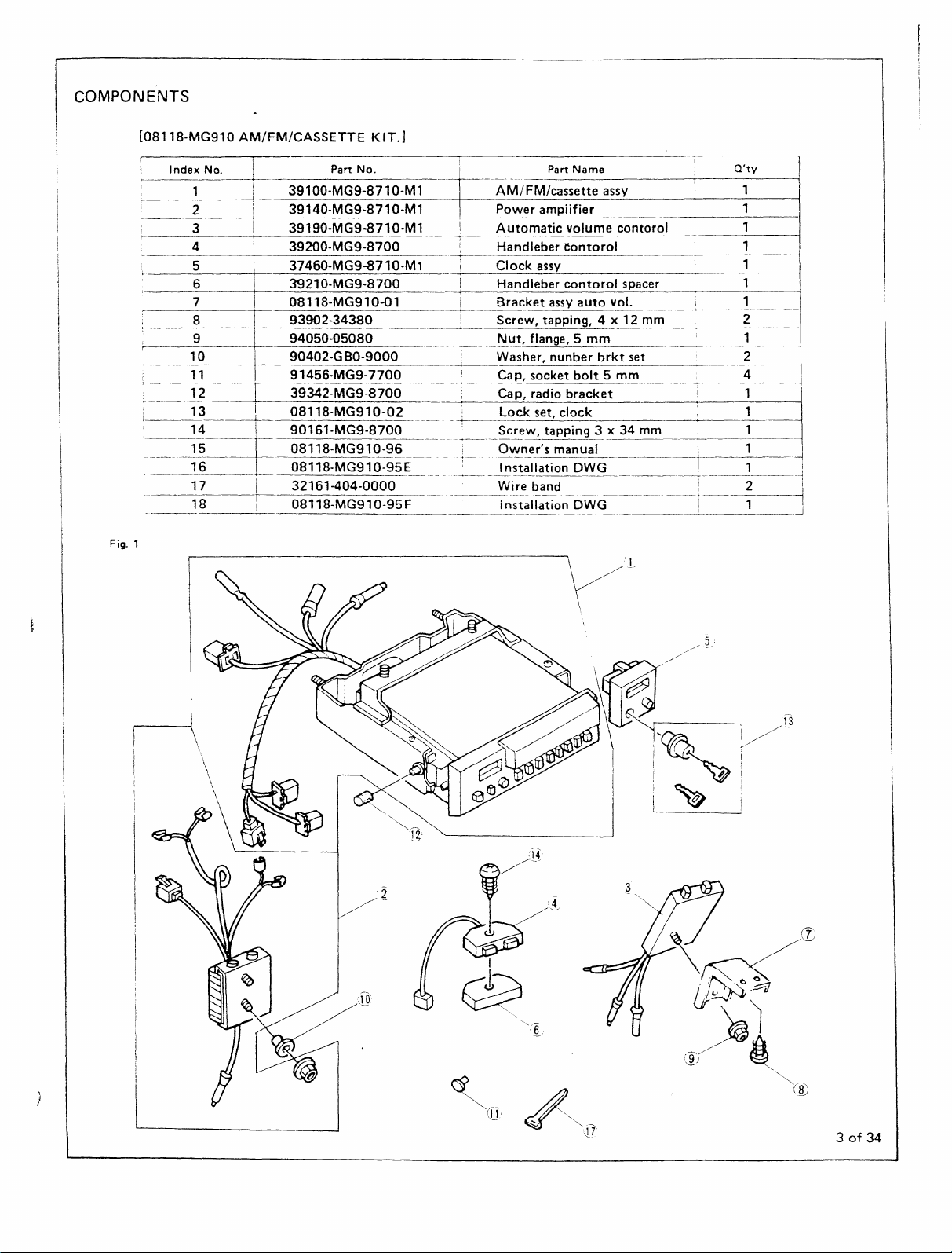
COMPONENTS
-
[08118-MG910
Index
~
~
c-
2
3
4
L----r=E
~
~_9~_L
~
: 13
l
Fig. 1
10
11
--~1-2---T
14 i
~~~-=~-
17 i 32161-404-0000
18 !
AM/FM/CASSETTE
No.
,
7
8
1
39100-MG9-8710-Ml
\-~
39140-MG9-8710-Ml
!
I
39190-MG9-8710-M1
I
I
39200-MG9-8700
I
37460-MG9-8710-M1 I
3921a-MG9-8700 !
Oa118-MG910-Q1
I
93902-34380
I
94050-05080
I 90402·GBO·9000
91456-MGS-7700
39342-MG9-8700
--+-I--o-a-11-8--M-G-S-10---0-2
-L
90161-MG9-8700
.
~E
~:~~::~~~~~:~~E
08118-MG910-95F
Part
No.
KIT.]
-------
I
I--------~-
--
---+
-----+-
----
___
-
!
I
-+-----------
!
-+------..-----
--+------
__
-~----
AM/FM/cassette
Power
Automatic
Handleber
Clock
Handleber
Bracket
Screw,
Nut,
Washer,
Cap,
Cap,
Lock
Screw,
Owner's
~;ta-II~DWG
Wi-;;band
----I-n~-t~lIation
-
Part
Name
assy
ampiifier
volume
contorol
assy
cantorol
assy
tapping,
flange, 5
nunber
socket
radio
bracket
set,
clock 1
tapping
manual
contorol
spacer
auto
vol.
4
_x12mm
mm
brkt
set
bolt
5 mm 4 I
3 x 34
mm
---
-~--r---
DWG
Q'ty
I
I
I
I
I
I,
\
1
1
1
1
1
1
1
2
1
2
I 1
\ 1
--~--2-----1
~'
1
1 !
1.J
--
~
\
I
~
3of34
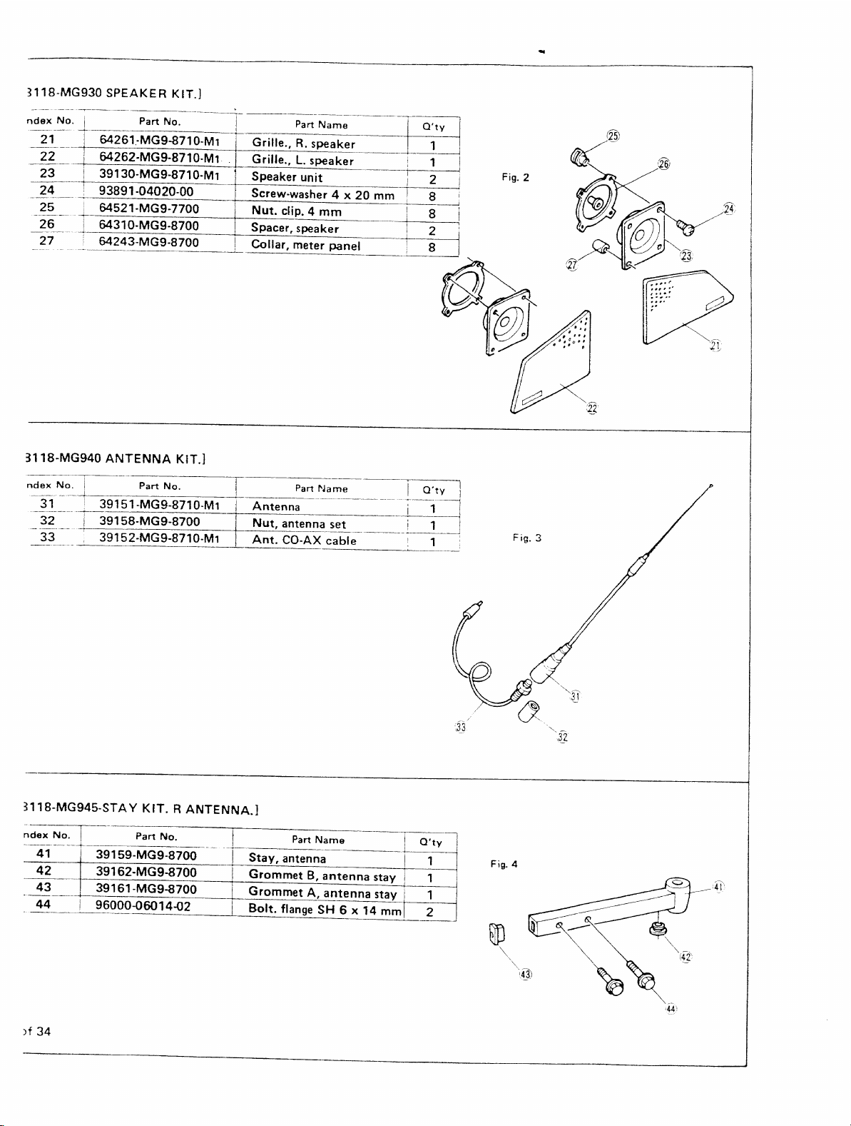
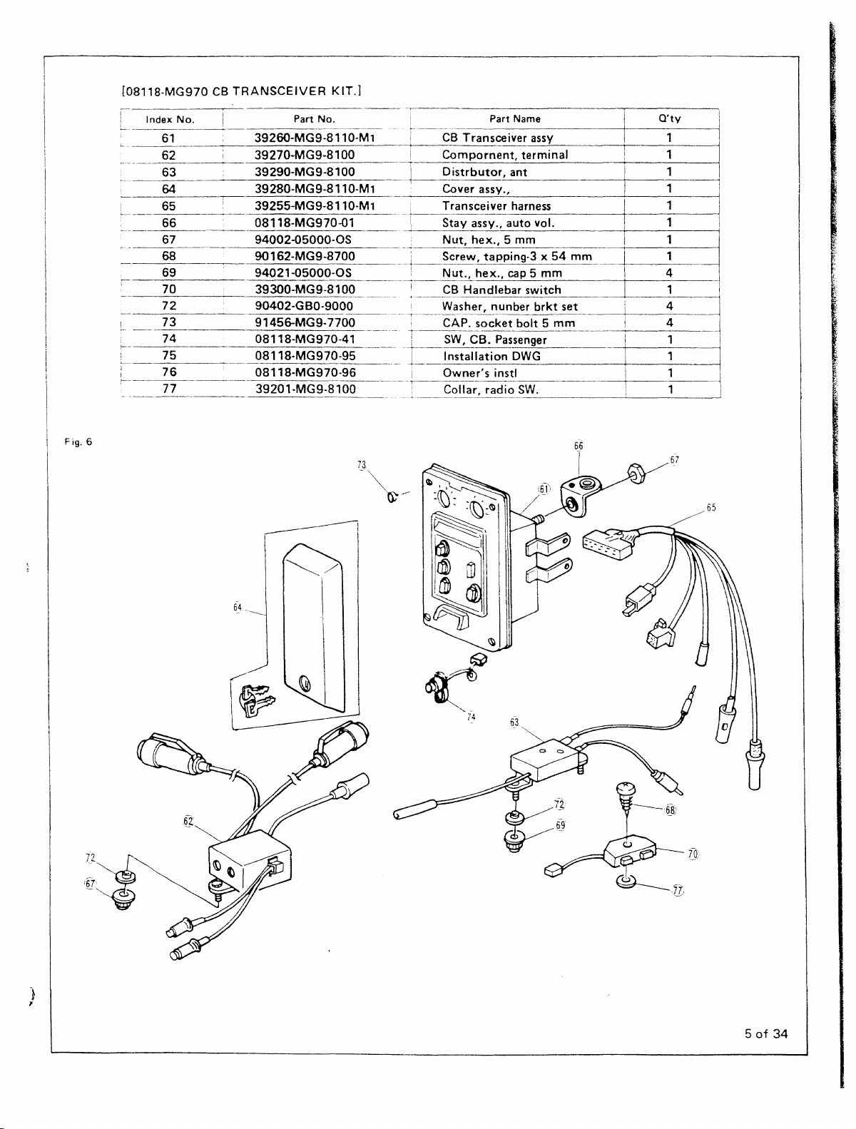
Fig.6
[Dal18-MG970
Index
61
62
63
64
65
No.
CB
TRANSCEIVER
I
I
39260-MG9-8110-M1
39270-MG9-8100
39290-MG9-8100
39280-MG9-8110-M1 Cover assy.,
i
39255-MGS-8110-M1
66 0811S-MG970-G1
-----
67
68
69
70
72
73
74
75
76
77
94002-05000-0S
90
94021-05000-05
39
90402-GBO-9000
91456-MG908118-MG970-41
08118·MG970-95
08118-MG970-96
3920
KIT.]
Part
No.
162-MG9-8700
300-MG
9-8100
7700
'-MG9-81
00
---
I
Part
Name
r--C-i3 Transceiver assy
Compornent,
I
o
istrbutor,
I
Transceiver harness
i
Stay
1
-+
i
I
-
j
--,-
---
T
1
----
i
-r
assy.,
Nut,
hex.,
Screw, tapping-3 x54mm
Nut.,
hex.,
CB
Handlebar
Washer, nunber
CAP.
socket
SW, CB. Passenger 1
Installation
Owner's
Collar, radIO
terminal
ant
auto
vol. 1
5 mm
cap
5
mm
switch
brkt
set
bolt 5
mm
DWG
instl
SW.
--------~-----~
----1-
a'ty
I
1
1
:
I
1
I
I
I
1
I
1
1
1
I
4
I
,
I
l
4
i
4
i
I
I
--
1
I
1
7,2
..
",~
.
'§T~
.----I
~/
65
I
~
74
)
1
5of34
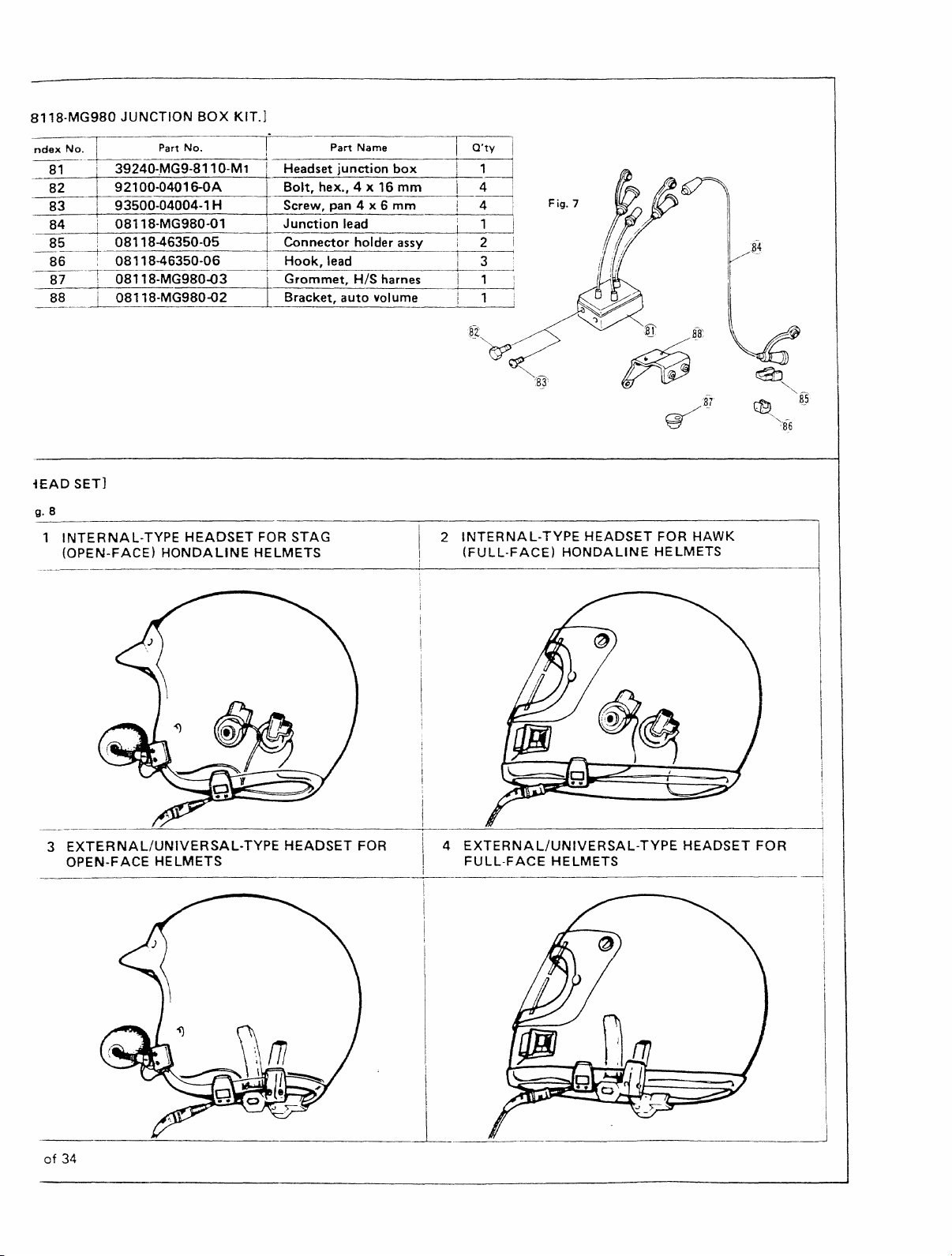
8118·MG980
ndex
N~_.
__
~--+-i
_
~_1._9_2_'_OO
83
84
85
----i-----------+-----------=-----T------<
86
-------
87
88
-lEAD
g. 8
INTERNAL-TYPE
(OPEN-FACE)
JUNCTION
_Ir-!
__
._P_ar_t
_3_9_24_0_·.,--M_G_9_-8_1_1_0_-M_1_~I.
__
i 93500-04004-1 H Screw, pan 4 x 6
i 08118·MG980-01
i
: 08118-46350-05
!
08118-46350-06
08118-MG980-03
0_8_'_18_-_M_G_9_80_-o_2
SET]
BOX
_N_o.
-_04_0_1_6-_0_A__-+_B_o_lt-=-,
HEADSET
HONDALINE
KIT.]
~I·
_H_ea_d_s_et--=j,--u_n_et_io_n_b_o_x
~
__
L Bracket,
FOR
HELMETS
p_art_N_am_e
_he_x---',,_4_x_'_6_m_m
Junction
Connector
Hook,
Grommet,
STAG
lead
holder assy
lead
HIS harnes
auto
volume
mm
--+_Q_·t_y
__
~
__
-+--
2
INTERNAL-TYPE
(FULL-FACE)
_
_
__
--...1
HEADSET
HONDALINE
FOR
HAWK
HELMETS
3
EXTERNAL/UNIVERSAL-TYPE
OPEN-FACE
HELMETS
-_~_.
of
34
HEADSET
FOR i 4
__
l
i
! \
I ----i
EXTERNAL/UNIVERSAL-TYPE
I
FULL-FACE
HELMETS
HEADSET
--------!
FOR
~
PRECAUTIONS
•
The
gu
ideisso
po
ssib
Ie
com
cassette
starting
to
select
being
• AIIcouplers,
color
you
components.
•
Careful
components
Asarule
their
Remember
to
malfunctions.
and
to
read
the
the
constructed.
coded.
think
handling
cables
broken
designed
binat
its
construct
manual
correct
connectors
You
to
assemble
is
important.
of
thumb
and
wires
that
rough
insulation
thatitcovers
ion
5 0 f
components.
your
system,
carefully
topics
may
of
for
and
finditeasier
the
the
preCISion
you
should
with
handling
andahost
the
50
you
the
\vires
cassette
greatest
can
of
Hi-Fi
Before
be
sure
may
system
are
than
and
Hi-Fi
handle
care.
lead
other
all
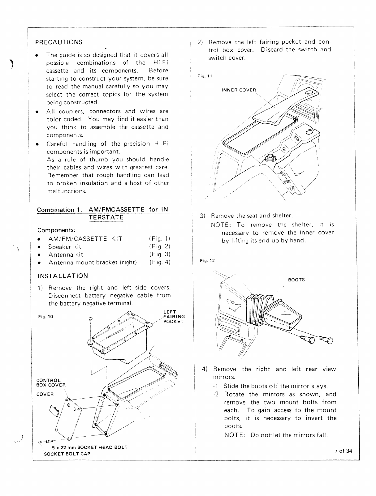
2)
Fig.
Remove
trol
switch
11
box
cover.
INNER
the
cover.
COVER
left
fairing
Discard
pocket
the
and
switch
con-
and
Combination
Components:
•
AM/FM/CASSETTE
•
•
•
Speaker
Antenna
Antenna
kit
kit
INSTALLATION
1)
Remove
Disconnect
the
battery
Fig.
10
CONTROL
BOX
COVER
COVER
,,__
~/~
/ I
~'_.~
~
5 x
22mmSOCKET
SOCKET
BOLT
1:
AM/FMCASSETT
TERSTATE
mount
the
bracket
right
battery
negative
~
I
I~~."
;/
~.
HEAD
CAP
KIT
(right)
and
left
negative
terminal.
"
i
BOLT
E
for
side
cabIefrom
C'
IN-
(Fig.
(Fig.2)
(Fig.3)
(Fig.4)
covers.
/FAIRING
,/
1)
LEFT
POCKET
3)
Fig.
-~~\/
Remove
NOTE:To
12
4)
Remove
mirrors.
-1
-2
the
necessary
by
lifting
Slide
the
Rotate
remove
each.
bo
Its, it
boots.
NOTE:
seat
the
To
and
remove
to
its
end
right
boots
the
the
gain
is
Do
shelter.
the
remove
up
and
off
mirrors
two
access
necessary
not
let
the
by
hand.
the
mirror
as
mount
the
shelter,
inner
left
shown,
bolts
to
the
to
mirrors
rear
stays.
invert
it
cover
view
and
from
mount
fall.
IS
the
7of34
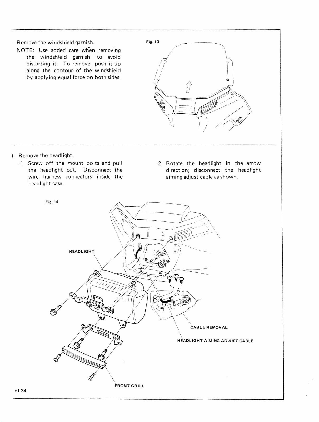
Remove
NOTE:
the
distorting
along
by
the
windshield garnish.
Use
added
windshield
"it.
To
the
contour
applying
equal forceonboth
care
when removing
garnish
remove, pushitup
of
the
to
avoid
windshield
sides.
Fig.
13
I
/1
~
<>
u
\
~
J
~
the
Remove
-1
Screw
the headlight out. Disconnect
wire harness connectors inside
headlight
headlight.
off
the
case.
Fig.
14
mount
HEADLIGHT
bolts
and
pull
the
the
\J
-2
Rotate
direction;
aiming adjust cable
the
I)
headlight in
disconnect
//~tf)
/
as
the
shown.
the
arrow
headlight
~
of
34
\\
FRONT
GRILL
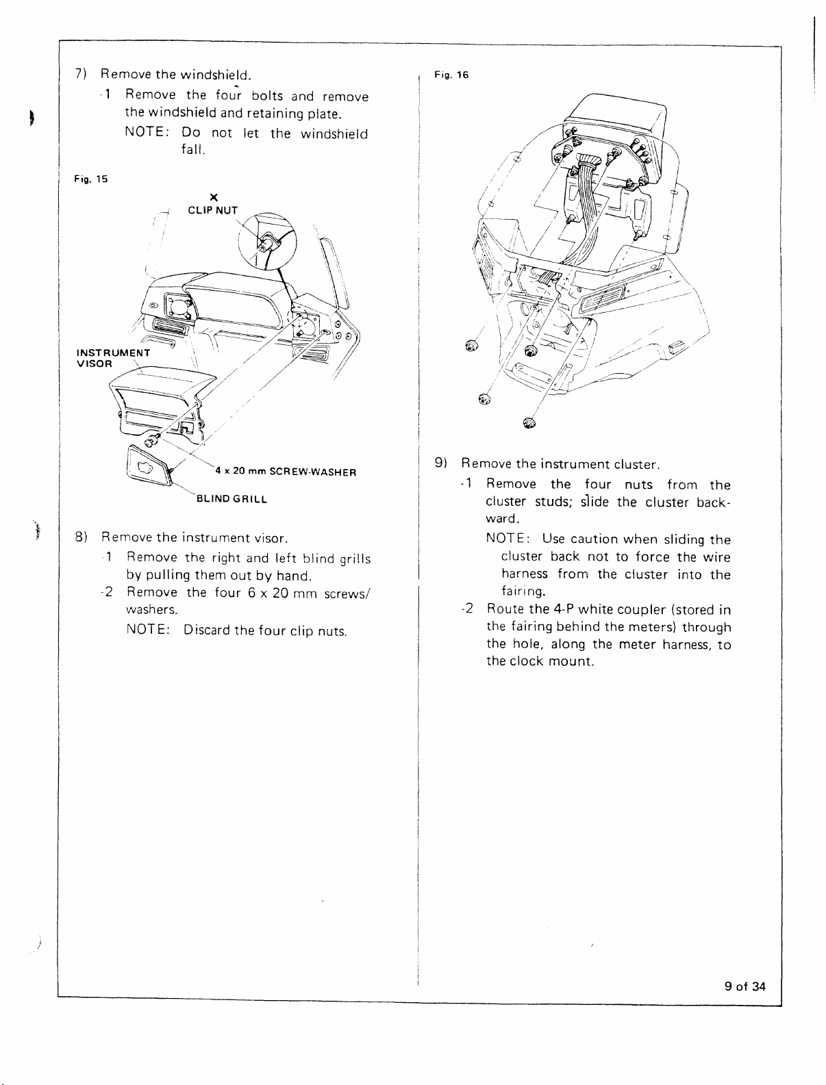
7)
Fig.
8)
Remove
-1
Remove
the
windshield
NOTE:
15
Remove
Remove
pulling
by
-2
Remove
washers.
NOTE:0 iscard
the
windshield.
the
Do
fall.
CLIP NUT
the
instru
the
the
fou~
and
not
)(
ment
right
them
four
bolts
and
retaining
let
the
visor.
and
left
outbyhand.
6 x
20
mm
the
four
cl ip nuts.
remove
plate.
windshield
blind
grills
screws/
Fig.
9)
16
Remove
-1
Remove
cl
ward.
NOTE: Use
-2
Route
the
the
the
the
uster
cluster
harness
fairing.
fairing
hole,
clock
instrument
the
studs;
caution
back
from
the
4-P
behind
along
mount.
four
si
ide
not
the
white
the
cluster.
nuts
thecluster
when
to
force
cluster
coupler
the
meters)
meter
from
back-
sliding
the
into
(stored
through
harness,
the
the
wire
the
in
to
9of34
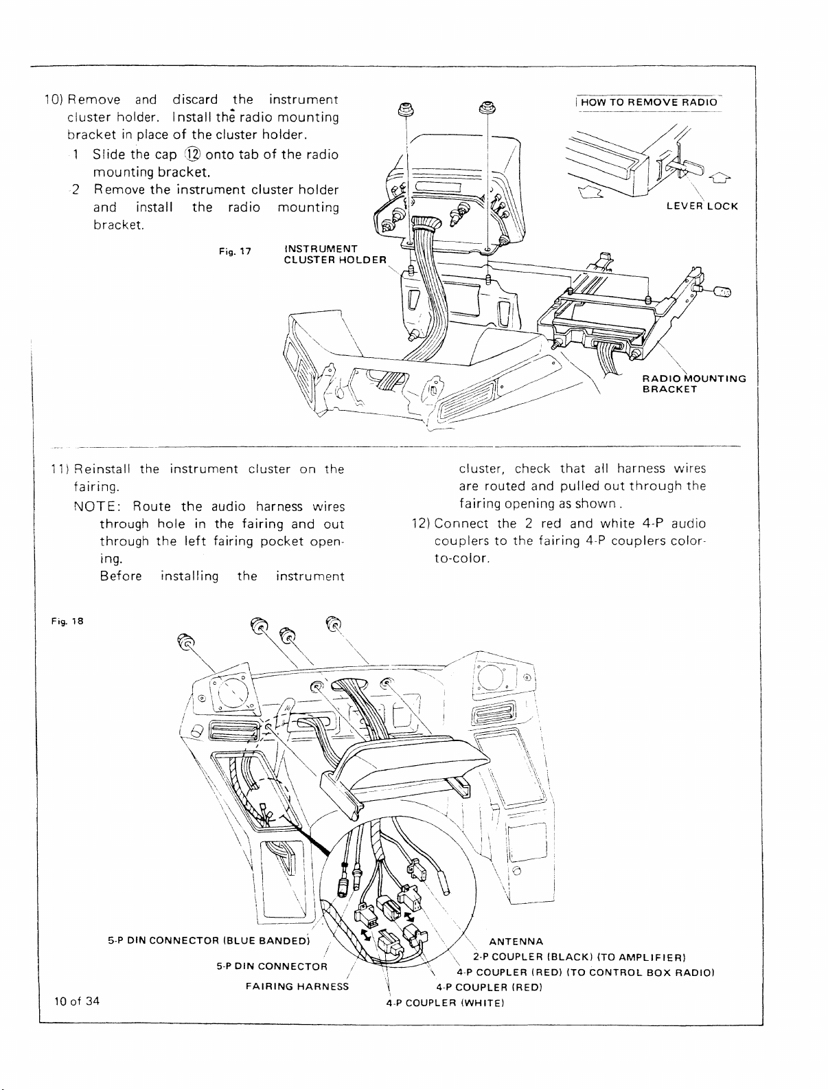
10)
Remove
cluster
bracket
1
Slide
mou
2
Remove
and
bracket.
and
discard
holder. I
nstall
in placeofthe
the
cap©onto
nting
bracket.
the
instrument
install
the
the
the
radio
cluster
tabofthe
radio
Fig.
17
instrument
mounting
holder.
cluster
mounting
INSTRUMENT
CLUSTER
radio
holder
HOLDER
""-,
i
HOWTOREMOVE
RADIO
~~o
Q
I!
RADIO
BRACKET
LEVER
"'~
MOUNTING
"
\\
LOCK
11)
Fig.
Reinstall
fairing.
NOT
E: R0 ute
through
through
ing.
Before
18
the
instrument
theaudi0 harness wi
hole
in
the
the
left
fairing
installing
cluster
fairing
the
and
pocket
instrument
on
open-
the
res
out
cluster, check
are
fairing
12}
Connect
couplerstothe
to-color.
that
routed
and
pulled
openingasshown.
the 2 red and
fairing
all harness wires
out
through
white
4-P
4-P
couplers
audio
color-
the
10of34
5-P
DIN
CONNECTOR
(BLUE
5-P
BANDED)
DIN
CONNECTOR
FAIRING
HARNESS
/
I
I \ 4-P
\~
I
4-P
4-P
COUPLER
COUPLER
ANTENNA
2-P
COUPLER
(WHITE)
COUPLER
(RED)
(BLACK)
(RED)
(TO
(TO
AMPLIFIER)
CONTROL
BOX
RADIO)
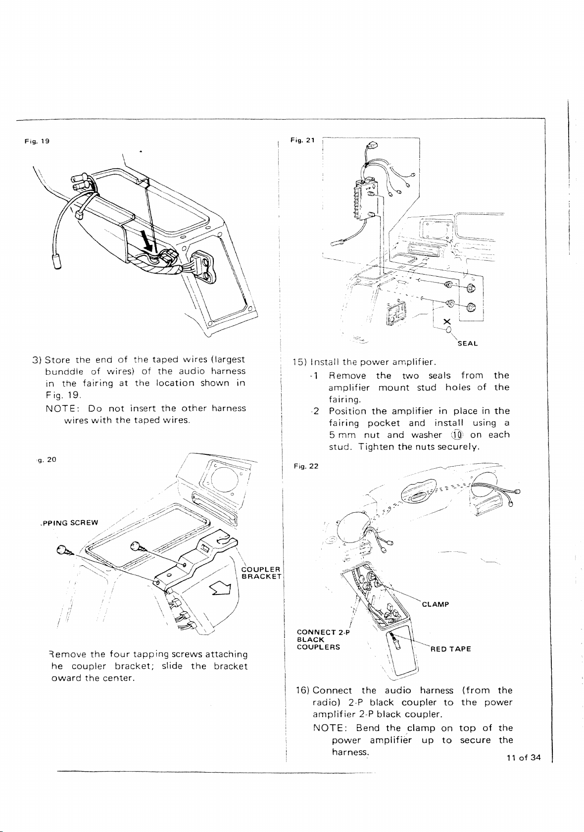
Fig.
3)
19
Store
:g.20
bunddle
in
the
F;g. 19.
NOTE:
wires
the
fairing
of
Do
with
end
of
vvires}
at
not
the
the
of
the
insert
taped
taped
the
location
the
wires.
wires
audio
other
(largest
harness
shown
harness
Fig.
21
15)Install
in
-1
the
Remove
amplifier
power
the
amplifier.
mount
two
stud
seals
holes
from
of
the
the
fairing.
-2
Fig.
22
Position
fairing
5
mm
stud.
the
pocket
nut
Tighten
amplifier
and
and
the
washer
nuts
in
placeinthe
install
(19)
securely.
using
on
a
each
,PPING
={emove
he
award
SCREW
the
coupler
the
four
bracket;
center.
tapping
screws
slide
attaching
the
bracket
20UPLER
BRACKET
I
Ii
!
I
I
I
CONNECT
!
BLACK
I
\
COUPLERS
I
16}
I
i
!
2·P
Connect
radio)
amplifier
NOTE:
power
harness.
.
,:.\~
,
'\
O\~
\m~
\\U'\
"~---.-----
the
audio
2-P
black
2-P
black
Bend
the
amplifier
CLAMP
harness
coupler
coupler.
,clamp
up
RED
to
on
to
TAPE
(from
the
top
secure
power
of
the
the
the
11of34
 Loading...