

Honda goldwing common tool 1979 schematic

Courtesy of Honda4Fun
www.hondafour.com www.honda4fun.com

,
Courtesy of Honda4Fun
www.hondafour.com www.honda4fun.com
rq
'.
-----------------_.~~
~
.MOTORCYCLE
Thank you very much for your having placed confidence in Honda genuine service tools.
This latest addition to Honda's line
features providing versatility
The primary design concept
cc
in the range from 50
is
requested that this manual
It
safer
and
more accurate repairs with minimumofeffort.
to 1000
COMMON
of
motorcycle service tools combines quality with design
and
economy.
is
to allow for complete interchangeability between models
cc,
contributing to reduced cost and tool stocks.
be
read through in order that you may result in faster,
TOOLS

r-/";
Courtesy of Honda4Fun
www.hondafour.com www.honda4fun.com
Courtesy of Honda4Fun
www.hondafour.com www.honda4fun.com
A1<,~
m:m:a
.
'~'.
_
..
\
~-
;
.
·"1'"
,
.
:,-.
.
,
----------------_.~
1 . GAUGE,
07401-0010000
• PURPOSE
This
position
ght
from
(Fig.
device
is
of
the
the
endofthe
1)
FLOAT
OF
USE
used
float
when
valve
selecting
by
measuring
carburetor
(DSlldlng
(})Uotlom
($JMllln
(4)Support
LEVEL
the
operating
the
to
the
scale
surface
scale
arm
hei-
float.
\
• METHOD
Remove
unted
in
the
carburetor
<Note>
For
the
'*
Set
in
f1o~t
just
from
scale
support
vehicles
carburetor
Method
float
Table
valve
touches
float
of
of
Jevel
1
the
the
operates
OF
chamber
engine
gauge
arm
(Fig.2-@)
(Fig
.2-@).
in
which
is
measuring
gauge
and
bend
the
topofthe
USE
fixed,
when
from
the
and
set
(Fig.2-<!))
the
measuring
set
and
adjusting
to
the
float
arm
the
float
carburetor
the
endofthe
and
to
the
end
to
this
position.
valueinthe
to
adjust
float
arm
valve
the
end
of
position
manual
so
(Fig.
(Fig.
dismo-
maof
the
of
or
the
2-@)
2-<D).
,-------,------,,--------,--_
Standard
5etting(lIIIII)
10.0(
PB40A
15.5 C50C, 50MB)
19.5
10.0(PA08Bl8l)
10.2
PA08
21.0
20.0
12.i
12.
10.i
19.0
20.0
20.0
21. 5
10.i
10.0
12.
10.
13.5
70
15.5
A
7.0
10.7
5
20.
20.0
21.0
20.
CSO
50,
C50M
550.
50. N
O,N
5550ZKl
50R.
50,
NF50.
0,
Y50
50
0, 5
ST50, 0
50,M
I
C10
0
70,
0,
75K2
Model
65
50
50,
50G
0
NY50
50K
1
XE50
1
~~TCllO
2
35
70l::J,
626B)
@
Model
XR80
ST90
CT90KS
CT90K9
CB90JX
MD90K2
GllO.CGI25
XLI00S,
CBI00K3
XLI25K4
CR125R
CDl25T,
CBUST.CBJ25T1,
MT125.XLI25,
CMI25T. I
C 125JX
CBI2SS. CDl2SS, SLUSS
CBI25S
CR125M2,
MRi75
CM185T
XR185
XLI85S
125
ClJ125T 2
LI25S
.
..
-
5TZ
125
2 17
25
____
~~·.--20·.(
~
Table
- '
Standard
SettinldlllfD)
21:0
-~-.
_..
..
-
21,0.-..-..
20,0-- _ Mlt250··
10.
20.6"·
20--'l?..-------·-
14.5
]2,5
12.5
--
j~'
1.
C'J2lWi~,
"XR250
Cli250T
th250
..
_-1.~O·
B400F
B4ooN,
X500
X 500
CB650
CB750KLTDZ
CBXl 0
00
00
750KS,
750A
750Z;CB750FZ
900
())Float
~)Float
~)Clearance
@End
@End
@End
Flg.2
..
-----,---------,
Model
CJ360T.
CL360
00.
00
GUoo,
GLSOO
3.
CB550K3
CB750F 3
'i7,'78)
valve
arm
of
main
of
support
of
carburetor
Standard
Setting(lIIIII)
18.5
18.5
14.5
20.0
15.5
19.0
21.0
21.0
20.0
15.5
15.5
14.5
15.5
14.5
12.5
14.5{ D42A1B
12.5
15.5
15.5
15.5
15.5
scale
arm
, L
• APPLIOABLE MODEL
May
be
used
in
common
motorcycles.
with
all
model
3
'"
Courtesy of Honda4Fun
www.hondafour.com www.honda4fun.com
Courtesy of Honda4Fun
www.hondafour.com www.honda4fun.com
',.
~
•
••
-----------
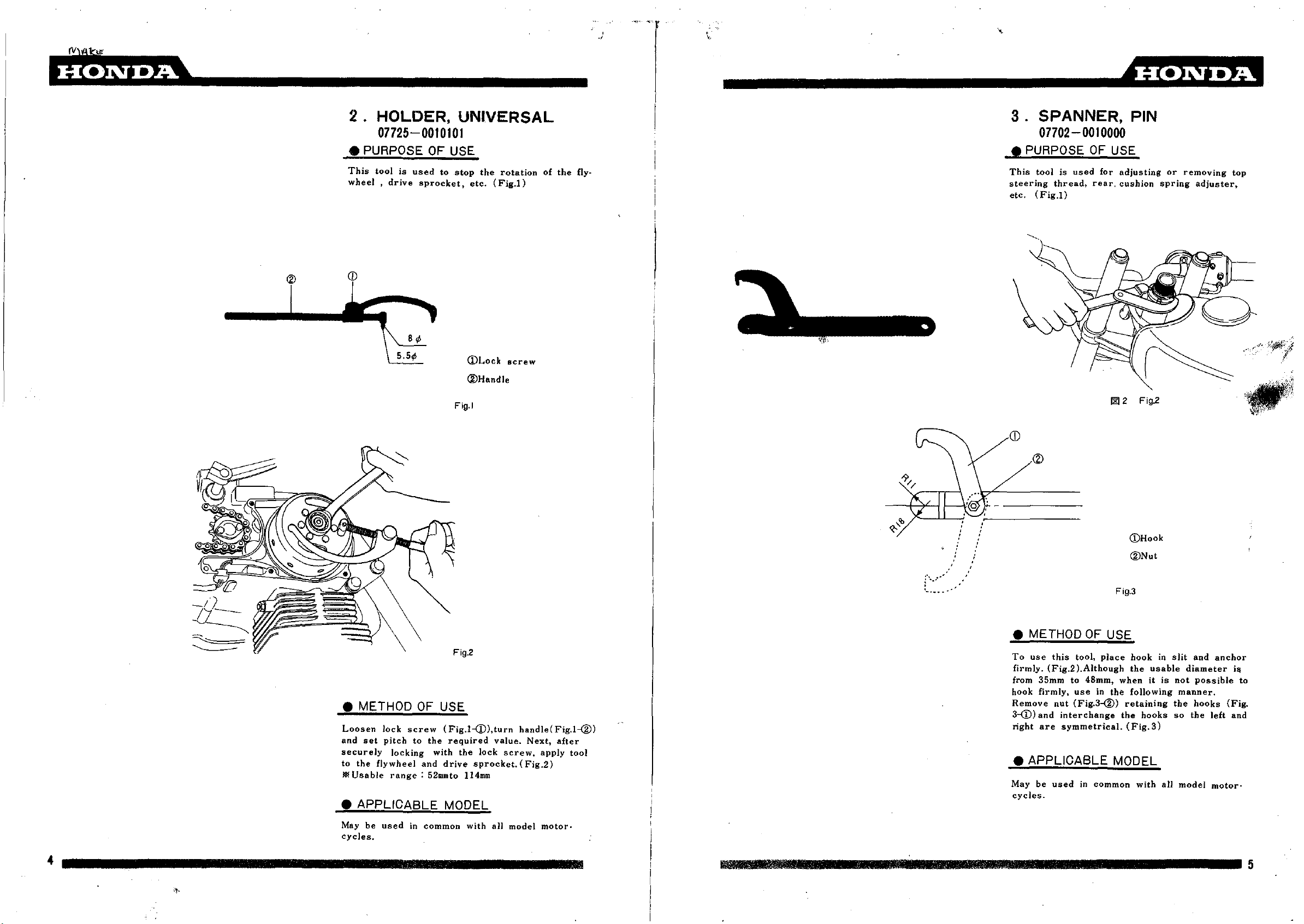
2.
HOLDER,
07725-0010101
• PURPOSE
This
toolisused
wheel.
drive
8';
5.5';
sprocket,
UNIVERSAL
OF
USE
to
stop
the
ete.
CDLock
®Handle
rotation
(Fig.I)
screw
------------------_.~
3.
SPANNER, PIN
07702-0010000
• PURPOSE
of
the
fly-
This
steering
etc.
toolisused
thread.
(Fig.I)
OF
rear.
for
USE
adjusting
cushion
or
spring
removing
adjuster,
top
Flg.1
• METHOD
Loosen
and
securely
to
)If
set
the
Usable
Jock
pitch
flywheel
screw
to
locking
range:
OF
the
with
and
52mmto
USE
(Fig.l-Q),turn
required
the
lock
drive
sprocket.
114mm
• APPLICABLE MODEL
handle(Fig.l-®)
value.
screw,
(Fig.2)
Next.
apply
after
tool
r-.·..·
'-...-.
(j)Hook
®Nut
"
• METHOD
To
use
this
tool,
firmly.
from
hook
Remove
3-(D)
right
(Fig.2).Although
35mm
to
firmly,
and
are
use
nut
(Fig.3-®)
interchange
symmetrical.
OF
place
48mm,
in
Flg.3
USE
hookinslit
the
whenitis
the
following
retaining
the
(Fig.
usable
hooks
3)
diameter
not
manner.
the
so
the
and
anchor
Possible
hooks
left
ifi
(Fig
and
to
.
• APPLICABLE MODEL
May
be
used
in
cycles
.
common
with
all
model
motor-
4
May
cycles.
be
used
in
common
with
aU
model
motor-
1l\1Il\l1l1I1II1lJZ
•••••••••
IIIIIIMI
••
IIIIIII
•••••••••••••••••••
5

Emm:a _
Courtesy of Honda4Fun
www.hondafour.com www.honda4fun.com
Courtesy of Honda4Fun
www.hondafour.com www.honda4fun.com
r
_ .4mmm
4.
WRENCH
ADJUSTING
07708-0030000
• PURPOSE
This
isatool
(Fig.1)
• METHOD
Use
wrench
adjusting
(Fig.l-@,@)matching
rew.
Loosen
et
gap
nual
or
nutinthis
nut
adjusting
to
the
Owner's
condition.
matching
(Fig.l-<D.®)
prescribed
SET, TAPPET
OF
USE
used
for
adjusting
(j)
07708-0030100
Wrench
®
07708Wrench
®
07708-
Adjusting(
@
07708-
Adjusting
Fig.1
Fig.2
OF
USE
the
outside
and
the
the
shape
nut
with
the
value
Manual)
and
(Fig.2)
tappet
ax 9
0030200
lOX 12
0030300
0030400
diameter
adjusting
of
the
wrench,
(refer
retighten
A)
(B)
adjusting
adjust
Service
gap.
or
tool
tapp-
adjusting
the
sc-
Ma-
C/CD/CL/SS/SO
ZSOA
ZOOM
ST/CT/SO
CB/TL/50
CB50-Kl
CFSO
CF70
TL/XESO
CYSO
MD/~/70/90
C/CS!CL/CD65
ST/CTl10
XL70
ATC70
CT70K8
XR75K4
USOO
C/CMI
crn
CS/CD/CL/SL/90
STOO
ATC90K3
CB90
CL/SL/90K CB/CD/CL/125S
CB/CL/SL/lOO
XLiOO
CGIlO
CB125-K5
MJ125
CB125B6
CR125M
CR125
CT125
CB/CD/125T
CBI25K6
CDI25K5
TLl25
CR125M2-M4
XLl25S
CB175-K6 CD175-K6
XL175
MR175
CM185T
CB/CLlroo
C/CTI200
XL250 XL350
SL250S
CR250M
M12,.
TL250
MR250
CB250G5
CB250T
XL250S
CB350F
CB400F
GL400
GLSOO
CB500
CBSSO
CB550F
CB750-K7
CB750F
CB750A
GLlOOO
55fC/SOM
Z50AK2
CBSOJ
C/CL/SL/CD!70
CT70M
CB/CLlZSS
XL125
CG125
CLl25
CJ250TCB360G
CB400T
CB400A
MODEL Wrench
-ZSOAK8
CY50K2 XE75
C/CDI70M
,
CB125JX
07708-0030100 07708-0030200 07708-0030300
'5
CLl75-K6
CJ360T
CL360
• APPLICABLE MODEL
8X9
Wrench
lOX
12
•
•
•
•
•
•
Adjusting Adjusting
(
A)
•
•
•
•
•
•
•
•
•
•
•
•
•
•
•
•
•
•
•
•
•
• •
•
•
•
•
•
•
•
• •
• •
• •
• •
•
• •
•
•
•
,
•
• •
•
(XL2SOj
•
•
•
•
•
•
•
•
•
•
•
•
•
•
•
•
•
•
•
•
•
• •
•
• •
•
•
•
•
•
•
•
•
•
07708-oo30~0
(B)
•
•
•
•
•
•
•
•
•
•
•
,
•
•
(XL250)
•
•
•
•
•
6
7
III
Jill
\
7
~----------------_.
Courtesy of Honda4Fun
www.hondafour.com www.honda4fun.com
Courtesy of Honda4Fun
www.hondafour.com www.honda4fun.com
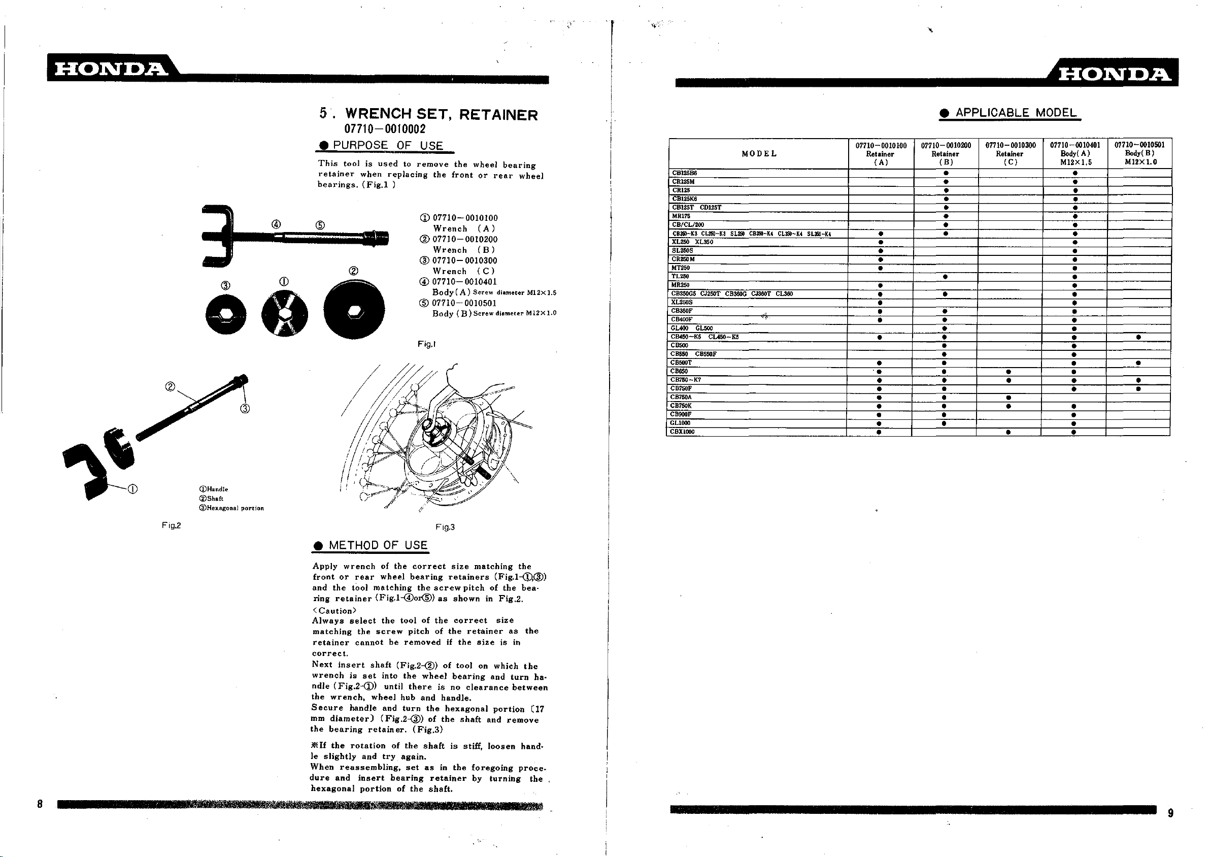
5.
WRENCH
SET,
RETAINER
------------------~
07710-0010002
• PURPOSE
This
retainer
bearings.
@ ®
000
toolisused
when
replacing
(Fig.!
®
)
OF
to
USE
remove
the
CD
07710-
Wrench
®
07710-0010200
Wrench
®
07710-
Wrench
007710-
Body
®
07710-
Body
Fig.!
the
front
(A)
(B)
wheel
or
0010100
(A)
(B)
0010300
(C)
0010401
Screw
0010501
Screw
bearing
rear
diameter
diameter
wheel
M12x
M12x
1.5
1.0
MODEL
CBl25B6
CRl25M
CRl25
CB125K6
CBl25T
CD125T
MR175
CB/CL/200
CB25)-K3
CL250-K3
SL250
CB3S0-K4
XL250 XL350
SL250S
CR25l)M
MT250
TL250
MR250
CB250GS CJ250T CB360G CJ360T CL360
XL250S
CIl350F
CB400F
GUOO
GL500
CBfSO-KS
CBSOO
CBSSO
CB500T
C"'O
CB7SO-K7
CB7SOF
CB7S0A
CB7SOK
CB900F
GLlOOO
CBXlOOO
CUSO-KS
CBSSOF
CL3S0-K4
.'
SL3S0-K4
07110-0010100
Retainer
(
A)
•
• •
•
• •
•
• •
•
•
•
• •
•
•
'.
• • •
•
•
• • • •
•
•
• • •
• APPLICABLE MODEL
07110-0010200 07110-0010300
Retainer Retainer
(B)
(e)
•
•
• •
•
• •
•
•
•
•
•
•
•
•
•
•
•
•
• •
•
•
•
•
•
07110-0010401
Body!
A)
MI2x 1,5
•
•
•
•
•
•
•
•
•
•
•
•
•
•
•
•
•
•
•
• •
•
•
07110
Body(B)
MI2x 1.0
0010501
•
•
•
@Handle
@Shaft
@Hex.agonal
Fig.2
8
PI
3
11;
'l1lll!111
portion
Iff TIWIi
• METHOD
Apply
front
and
ring
<
Always
matching
retainer
correct.
Next
wrench
ndle
the
Secure
mm
the
.*Elf
Ie
When
dure
hexagonal
litif
m
wrench
or
the
retainer
Caution>
insert
(Fig.2-(D)
wrench,
diameter)
bearing
the
slightly
reassembling,
and
rmiiEI
rear
tool
select
the
cannot
shaft
is
set
wheel
handle
retainer.
rotation
and
insert
portion
...
OF
USE
of
the
correct
wheel
bearing
matching
(Fig.l-@or@)
the
toolofthe
screw
ilIIlBl.1
pitch
be
removed
(Fig.2-@)
into
the
until
there
hub
and
turn
(Fig.2-@)
of
the
try
again.
set
bearing
of
the
PI
(Fig.3)
Flg.3
the
screw
as
of
wheel
is
and
handle.
the
of
the
shaft
asinthe
retainer
shaft.
rlil
size
retainers
pitchofthe
shown
correct
the
retainer
if
the
of
tool
bearing
no
clearance
hexagonal
shaft
is
stiff,
Rm
IIJfli
matching
(Fig.l--cD.@)
in
Fig.2.
size
size
is
on
which
and
portion
and
loosen
foregoing
by
turning
the
bea-
as
the
in
the
turn
between
remove
hand·
proce.
ha-
07
the
9
 Loading...