


2017
Clarity Fuel Cell
OWNER’S MANUAL

California Proposition 65 Warning
WARNING: This product contains or emits
chemicals known to the state of California to cause
cancer and birth defects or other reproductive
harm.
NOTICE
00X31-TRT-6001 2017 Clarity Fuel Cell Owner's Manual - Ver. 2 AOM05449
To read data recorded by an EDR, special equipment is required,
and access to the vehicle or the EDR is needed. In addition to the
vehicle manufacturer, other parties, such as law enforcement, that
have the special equipment, can read the information if they have
access to the vehicle or the EDR.
Event Data Recorders
This vehicle is equipped with an event data recorder (EDR).
The main purpose of an EDR is to record, in certain crash or near
crash-like situations, such as an air bag deployment or hitting a
road obstacle, data that will assist in understanding how a vehicle’s
systems performed. The EDR is designed to record data related
to vehicle dynamics and safety systems for a short period of
time, typically 30 seconds or less. The EDR in this vehicle is
designed to record such data as:
• How various systems in your vehicle were operating;
• Whether or not the driver and passenger safety belts were
buckled/fastened;
• How far (if at all) the driver was depressing the accelerator
and/or brake pedal; and,
• How fast the vehicle was traveling.
These data can help provide a better understanding of the
circumstances in which crashes and injuries occur. NOTE: EDR data
are recorded by your vehicle only if a non-trivial crash situation
occurs; no data are recorded by the EDR under normal driving
conditions and no personal data (e.g., name, gender, age, and
crash location) are recorded. However, other parties, such as law
enforcement, could combine the EDR data with the type of
personally identifying data routinely acquired during a crash
investigation.
The data belongs to the vehicle owner and may not be accessed by
anyone else except as legally required or with the permission of the
vehicle owner.
Service Diagnostic Recorders
This vehicle is equipped with service-related devices that record
information about powertrain performance. The data can be used
to verify emissions law requirements and/or help technicians
diagnose and solve service problems. It may also be combined with
data from other sources for research purposes, but it remains
confidential. Some diagnostic and maintenance information is
uploaded to Honda upon vehicle start up.
California Perchlorate Contamination Prevention Act
The airbags, seat belt tensioners, and CR type batteries in this
vehicle may contain perchlorate materials - special handling may
apply. See www.dtsc.ca.gov/hazardouswaste/perchlorate/
As you read this manual, you will find information that is preceded
by a symbol. This information is intended to help you avoid
damage to your vehicle, other property, or the environment.

Fuel Cell Monitoring System
3DANGER
3WARNING
3CAUTION
This vehicle is equipped with a monitoring system that compiles
data about your vehicle and driving conditions and transmits that
data to Honda at regular intervals as determined at the discretion
of Honda. This data includes information on but not limited to the
following:
● Vehicle location, distance driven, warning indicators and
messages, and vehicle speed
● Fuel cell system control and power generation
The system does not record voice or images.
Honda or any third party entrusted by Honda understands that
such data is customers’ personal information and shall treat that
data accordingly. Data collected is used for the sole purpose of
technical diagnoses, research, and development of the vehicle.
You will find this important safety information in a variety of forms,
including:
● Safety Labels - on the vehicle.
● Safety Messages - preceded by a safety alert symbol
one of three signal words: DANGER, WARNING, or CAUTION.
These signal words mean:
You WILL be KILLED or SERIOUSLY HURT if
you don’t follow instructions.
You CAN be KILLED or SERIOUSLY HURT if
you don’t follow instructions.
You CAN be HURT if you don’t follow
instructions.
3
and
A Few Words About Safety
Your safety, and the safety of others, is very important. And
operating this vehicle safely is an important responsibility.
To help you make informed decisions about safety, we have
provided operating procedures and other information on labels and
in this manual. This information alerts you to potential hazards that
could hurt you or others.
Of course, it is not practical or possible to warn you about all the
hazards associated with operating or maintaining your vehicle. You
must use your own good judgment.
● Safety Headings - such as Important Safety Precautions.
● Safety Section - such as Safe Driving.
● Instructions - how to use this vehicle correctly and safely.
This entire book is filled with important safety information - please
read it carefully.

Contents
This owner’s manual should be considered a permanent part of the
vehicle and should remain with the vehicle when it is sold.
This owner’s manual covers all models of your vehicle. You may find
descriptions of equipment and features that are not on your
particular model.
Images throughout this owner’s manual (including the front cover)
represent features and equipment that are available on some, but
not all, models. Your particular model may not have some of these
features.
The information and specifications included in this publication were
in effect at the time of approval for printing. Honda Motor Co., Ltd.
reserves the right, however, to discontinue or change specifications
or design at any time without notice and without incurring any
obligation.
2 Safe Driving P. 41
For Safe Driving P. 42 Seat Belts P. 46 Airbags P. 53
2 Instrument Panel P. 83
Indicators P. 84 Gauges and Displays P. 114
2 Controls P. 129
Clock P. 130 Locking and Unlocking the Doors P. 131
Operating the Switches Around the Steering Wheel P. 151
Interior Lights/Interior Convenience Items P. 175
2 Features P. 193
Audio System P. 194 Audio System Basic Operation P. 200
Customized Features P. 284 HomeLink® Universal Transceiver P. 309
2 Driving P. 345
Before Driving P. 346 Towing a Trailer P. 351
Multi-View Rear Camera P. 420 Refueling P. 422
2 Maintenance P. 427
Before Performing Maintenance P. 428 Maintenance MinderTM P. 431
Checking and Maintaining Wiper Blades P. 443
Climate Control System Maintenance P. 457 Cleaning P. 458
2 Handling the Unexpected P. 465
If a Tire Goes Flat P. 466 Handling of the Jack P. 478
If Hydrogen Gas is Leaking P. 487 Indicator, Coming On/Blinking P. 489
When You Cannot Unlock the Hydrogen Fuel Lid P. 503
2 Information P. 505
Specifications P. 506 Identification Numbers P. 508
Warranty Coverages P. 511 Authorized Manuals P. 513

Contents
Child Safety P. 68 Safety Labels P. 81
Opening and Closing the Trunk P. 143 Security System P. 146 Opening and Closing the Windows P. 149
Adjusting the Mirrors P. 167 Adjusting the Seats P. 169
Climate Control System P. 185
Audio Error Messages P. 273 General Information on the Audio System P. 277
Bluetooth® HandsFreeLink® P. 312
When Driving P. 352 Braking P. 404 Parking Your Vehicle P. 419
Fuel Economy P. 425
Maintenance Under the Hood P. 435 Replacing Light Bulbs P. 441
Checking and Maintaining Tires P. 446 12-Volt Battery P. 455 Remote Transmitter Care P. 456
Accessories and Modifications P. 463
Power System Won’t Start P. 479 Jump Starting P. 482 Overheating P. 485
Fuses P. 494 Emergency Towing P. 502
When You Cannot Open the Trunk P. 504
Quick Reference Guide
Safe Driving
Instrument Panel
Controls
Features
Driving
Maintenance
Handling the Unexpected
Information
Index
P. 4
P. 41
P. 83
P. 129
P. 193
P. 345
P. 427
P. 465
P. 505
P. 516
Devices that Emit Radio Waves P. 509 Reporting Safety Defects P. 510
Customer Service Information P. 514
Quick Reference Guide
Quick Reference Guide
❙
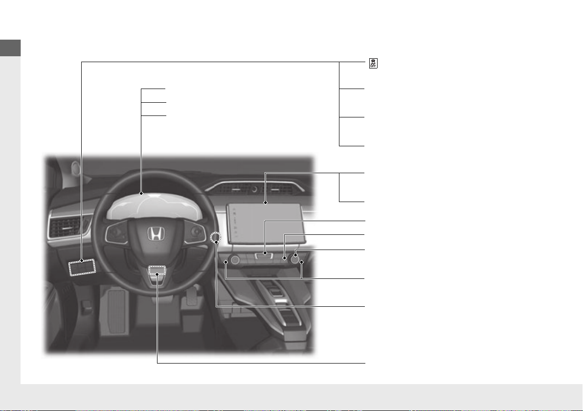
Steering Wheel Adjustments
(P 166)
❙
(Vehicle Stability Assist (VSA®)
System OFF) Button
(P 393)
❙
Road Departure Mitigation (RDM)
Button
(P 368)
❙
System Indicators
(P 84)
❙
Gauges
(P 114)
❙
Collision Mitigation Braking SystemTM
(CMBS
TM
) OFF Button
(P 414)
❙
Head-Up Display Buttons
(P 125)
❙
Driver Information Interface
(P 117)
❙
Navigation System
() See the Navigation System Manual
❙
Audio System
(P 194)
❙
Hazard Warning Button
❙
Climate Control System
(P 185)
❙
Rear Window Defogger
(P 163)
❙
POWER Button
(P 151)
❙
Seat Heater Buttons
(P 183)
Visual Index
4
Quick Reference Guide
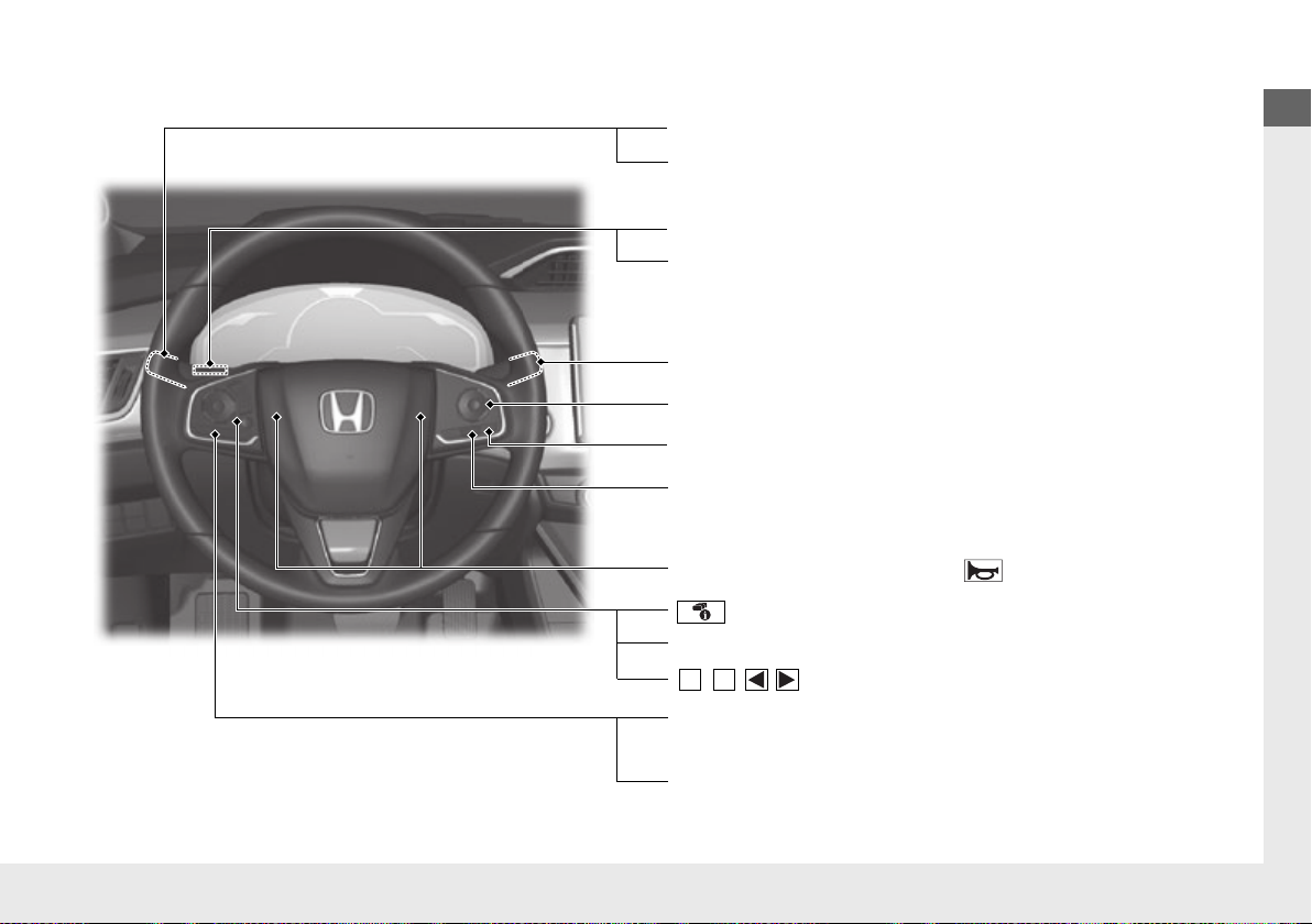
❙
Wipers/Washers
(P 159)
❙
Headlights/Turn Signals
(P 154, 155)
❙
Brightness Control
(P 161)
❙
LaneWatchTM
(P 402)
❙
TRIP Button
(P117, 119)
❙
Interval Button
(P 379)
❙
Lane Keeping Assist System (LKAS) Button
(P 387)
❙
Adaptive Cruise Control (ACC) with Low
Speed Follow (LSF) Buttons
(P 371)
❙
(Display/Information) Button
(P117 )
❙
/ // Buttons
(P117, 197)
3
4
❙
ENTER Button
(P117 )
❙
Navigation System Voice Control Buttons
() See the Navigation System Manual
❙
Bluetooth® HandsFreeLink® System
Voice Control Buttons
(P 312)
❙
Horn (Press an area around .)
5
Visual Index
Quick Reference Guide
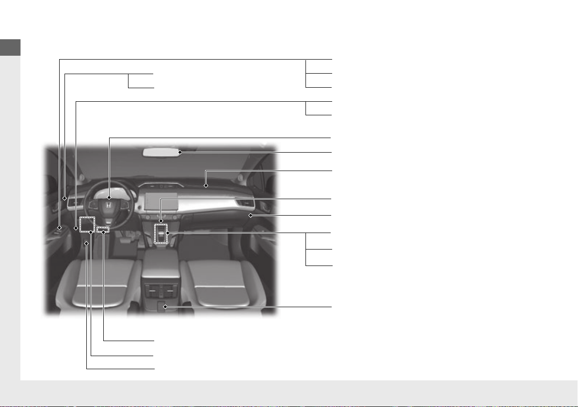
❙
Power Window Switches
(P 149)
❙
Trunk Opener
(P 143)
❙
Driver’s Knee Airbag
(P 60)
❙
Door Mirror Controls
(P 168)
❙
Power Door Lock Master Switch
(P 141)
❙
Hydrogen Fuel Lid Release Button
(P 423)
❙
Memory Buttons
(P 165)
❙
SET Button
(P 165)
❙
Interior Fuse Box
(P 496)
❙
Automatic Brake Hold Button
(P 407)
❙
Driver’s Front Airbag
(P 56)
❙
Passenger’s Front Airbag
(P 56)
❙
Rearview Mirror
(P 167)
❙
SPORT Button
(P 363)
❙
Glove Box
(P 177)
❙
Electric Parking Brake Switch
(P 404)
❙
Shift Button
Electronic Gear Selector
(P 357)
❙
Accessory Power Socket
(P 181)
❙
Hood Release Handle
(P 436)
6
Quick Reference Guide
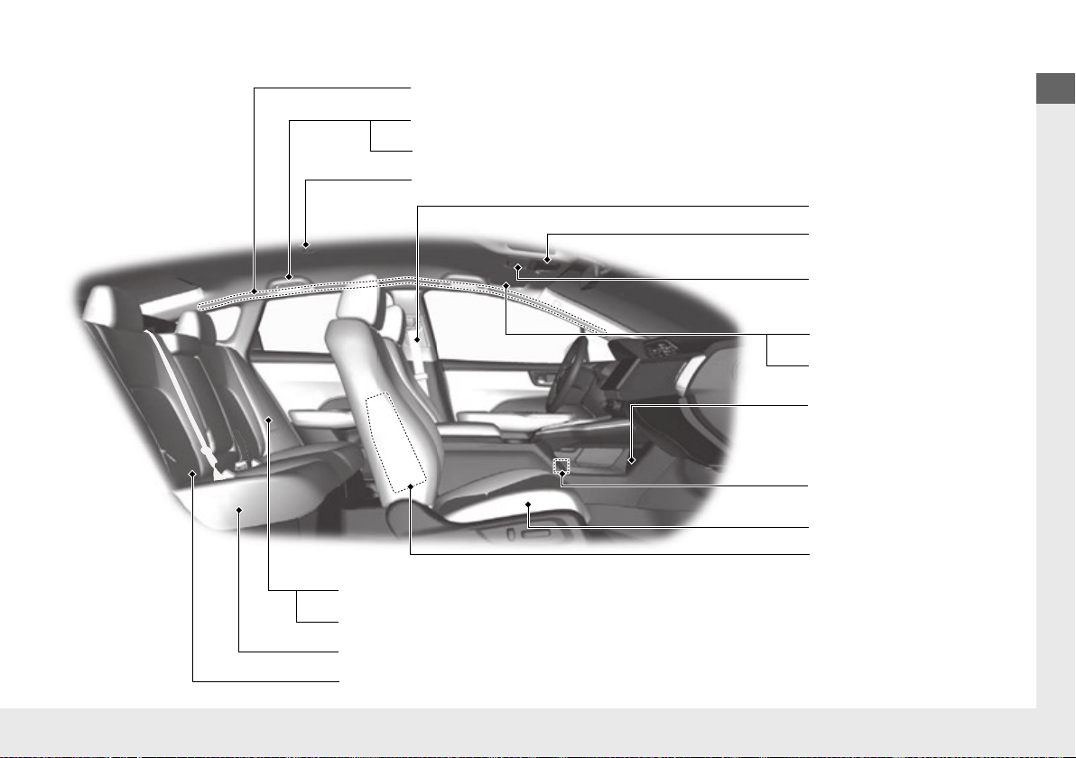
❙
Side Airbags
(P 62)
❙
Side Curtain Airbags
(P 64)
❙
Seat Belts
(P 46)
❙
Seat Belt (Installing a Child Seat)
(P 75)
❙
Rear Seat
❙
Coat Hook
(P 182)
❙
Map Lights
(P 176)
❙
Sun Visors
❙
Vanity Mirrors
❙
Seat Belt to Secure a Child Seat
(P 77)
❙
Map Lights
(P 176)
❙
Grab Handle
❙
Sunglasses Holder
(P 184)
❙
Accessory Power
Socket
(P 181)
❙
Front Seat
(P 169)
❙
USB Ports
(P 195)
❙
LATCH to Secure a Child Seat
(P 73)
7
Visual Index
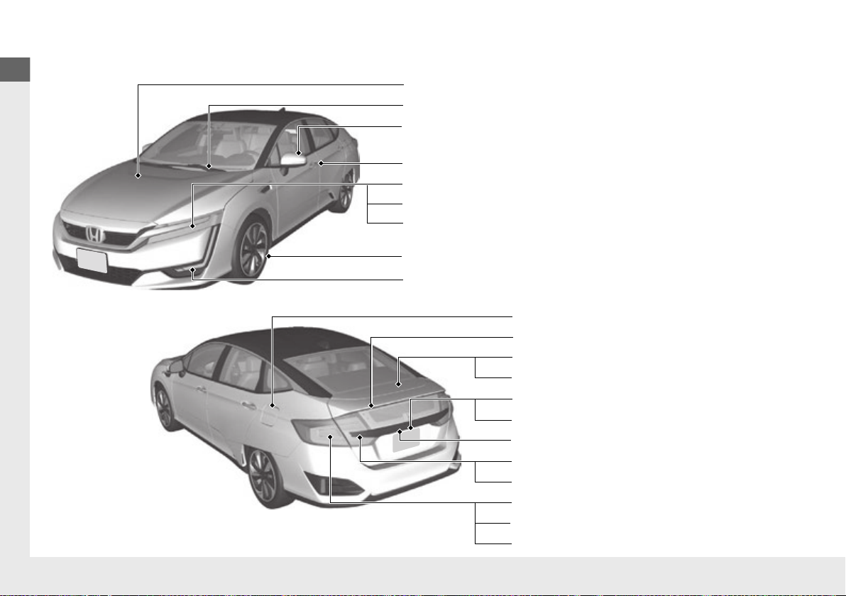
Quick Reference Guide
❙
Maintenance Under the Hood
(P 435)
❙
Windshield Wipers
(P 159, 443)
❙
Tires
(P 446, 466)
❙
Door Lock/Unlock Control
(P 133)
❙
Power Door Mirrors
(P 168)
❙
Headlights
(P 155, 441)
❙
Front Side Marker Lights
(P 155, 441)
❙
Front Turn Signal Lights
(P 154, 441)
❙
How to Refuel
(P 423)
❙
High-Mount Brake Light
(P 442)
❙
Emergency Trunk Release Lever
(P 145)
❙
Opening/Closing the Trunk
(P 143)
❙
Tail/Rear Side Marker Lights
(P 442)
❙
Brake Lights
(P 442)
❙
Rear Turn Signal Lights
(P 442)
❙
Back-Up Lights
(P 442)
❙
Taillights
(P 442)
❙
Trunk Release Button
(P 144)
❙
Rear License Plate Light
(P 442)
❙
Multi-View Rear Camera
(P 420)
❙
Parking/Daytime Running Lights
(P 155, 158, 441)
8

Quick Reference Guide
Characteristics of Fuel Cell Vehicles
A fuel cell vehicle (FCV) converts hydrogen gas into electricity which is used to power an electric motor. The FC (fuel cell) system comprises
of hydrogen tanks and an FC stack, as well as other components, and requires a constant supply of hydrogen fuel, and proper cooling and
ventilation to generate electricity.
The FC stack is the main power unit which comprises of a series of fuel cells joined together or “stacked” on one another. Within each fuel
cell, hydrogen reacts with oxygen to create an electric current which is used to not only power the motor but also charge a High Voltage
battery. This High Voltage battery provides supplementary power to assist the FC power system when the vehicle is subjected to heavy
acceleration.
Unlike vehicles that use internal combustion engines, FC vehicles emit no harmful emissions such as CO
environmentally friendly. The only substance discharged from the tailpipe is water, in the form of both liquid and vapor.
FC Stack
Fuel cell power output may decline faster than usual under the following circumstances:
● The vehicle is frequently used in sub-zero temperatures over extended periods of time.
● The vehicle is repeatedly left in standby state for extended periods of time.
● The FC system is subjected to frequent starting and stopping.
● Salt water has permeated the air cleaner element.
u Replace the air cleaner element and clean the surrounding area.
● The vehicle is driven extensively in areas whose air contains high levels of:
Dust
Sulfur (common to hot spring and volcanoes)
Organic solvents, e.g., paints and thinners
Amine-related substances, e.g., ammonia
Chlorinated substances, e.g., salt and snow-melting agents
u Once the vehicle is driven in a normal environment again, fuel cell power output will return over time.
In the following circumstances, power output may be temporarily limited:
● You are repeatedly accelerating and decelerating aggressively.
● You are ascending a slope or driving at high altitudes above 6,562 feet (2,000 meters).
2 Driver Information Interface Warning and Information Messages (P102)
and NOx, and are thus considered
2
9

Quick Reference Guide
Fuel Cell Power System
The fuel cell power system regulates the fuel cells to maintain efficient power generation in various driving conditions. The power system is
unique to fuel cell vehicles and differs to that of conventional internal combustion vehicles or electric vehicles in the following ways:
● Depending on circumstances, the system may need to adjust the condition of the fuel cells before shutting down; therefore, the power
system may continue to operate even after the power mode is set to OFF.
● In cold temperatures, the power system may take more time to start or stop than usual as the fuel cells need to be conditioned before
they can generate power.
Hydrogen Tanks
● Outline
The hydrogen tanks are the storage containers that house the compressed hydrogen gas.
● Inspection
Owners of fuel cell vehicles are required by law to have these tanks inspected periodically. Filling a hydrogen tank with compressed
hydrogen gas is prohibited by law if the tank has not passed inspection or if the tank has expired.
The hydrogen tanks are affixed with an expiration date. This date is also affixed to the underside of the hood and the hydrogen fuel lid. If a
tank has expired, replace it immediately.
● Disposal
Disposal of hydrogen tanks or hydrogen tank valves must be done in accordance with the pertinent rules and regulations of the state or
region within which the tanks or valves are to be disposed of. For details, consult an authorized Honda Clarity Fuel Cell dealer.
● Theft
If your fuel cell vehicle is stolen, be sure to inform the police that the vehicle is equipped with tanks filled with compressed hydrogen gas.
Refueling
Fuel cell vehicles need hydrogen to run. Refuel with compressed hydrogen gas at an authorized hydrogen filling station.
2 Refer to the Navigation System Manual
10

Quick Reference Guide
Sounds Unique to the Fuel Cell Vehicle
When you first start driving this vehicle, you likely will hear some unfamiliar sounds, particularly when you first turn on the power system,
while driving, and just after parking. Some of these sounds are unique to this vehicle’s powertrain, fuel, and climate control systems; others
are similar to sounds generated by conventional automobiles that typically are masked by louder noises absent from a vehicle of this design.
These sounds are not a cause for concern, and you will soon recognize them as normal and thus be able to detect any new or unusual noise
should one develop.
Certain sounds associated with your vehicle may be caused by:
● Pressurized intake air being released through the rear of the vehicle.
u This can happen if the accelerator is released suddenly when the vehicle is under a heavy load, such as when climbing a hill.
● The power system warming up.
u This sound is particularly loud when temperatures are extremely low (below –4°F [–20°C]).
● Hydrogen gas flowing through the fuel line during refueling.
11
Quick Reference Guide
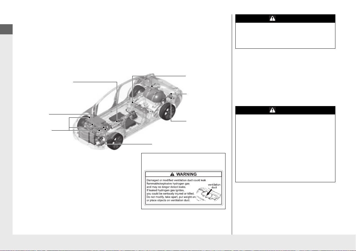
Fuel Cell Vehicle Precautions
Hydrogen
Leak
Detection
System
FC Stack
Hydrogen
Leak
Detection
System
Hydrogen Fuel
Receptacle
Hydrogen Tanks
Hydrogen Pipelines
Hydrogen-retaining components
●
Hydrogen tanks
●
Hydrogen pipelines
●
FC stack
Components with a warning label
●
Hydrogen tanks
●
Compressed hydrogen pipeline
●
Hydrogen fill pipeline
●
FC stack
●
Hydrogen ventilation duct
Hydrogen Leak Detection System locations
●
In the motor compartment
●
Above the hydrogen fuel receptacle
Hydrogen Ventilation Duct a
Label
a Hydrogen Ventilation Duct
Hydrogen-related Components
Fuel cell vehicles have hydrogen-related components such as hydrogen tanks, an FC stack,
and hydrogen pipelines.
Labels with handling warnings are attached to these components.
WARNING
Never leave the fuel cell vehicle in standby
state in an enclosed area that has limited
ventilation as there is a risk of oxygen
deprivation.
Fuel cells consume oxygen when generating
electricity. If the vehicle is left in standby
state in an enclosed area, the air may
become deprived of oxygen, resulting in
asphyxiation of any person(s) in the area.
Make sure the area is well ventilated before
turning the power system on. If the vehicle
is in a garage, keep the door open.
12
WARNING
Do not attempt to modify, install, or
disassemble the hydrogen-related
components.
The hydrogen-related components are
filled with hydrogen gas. Removing or
disassembling these components may cause
a hydrogen gas leak which can lead to a fire
or explosion.
If you notice anything unusual about your
vehicle, consult an authorized Honda
Clarity Fuel Cell dealer.
Quick Reference Guide
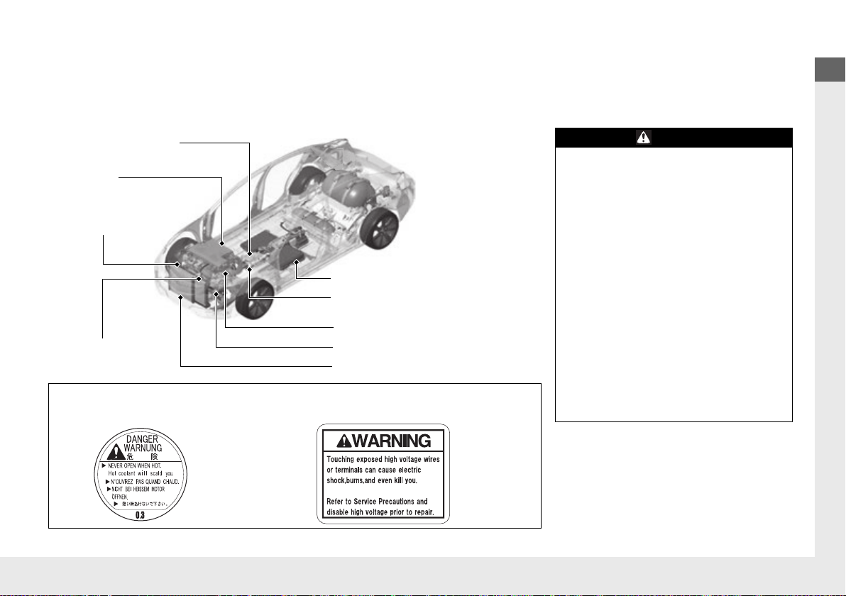
WARNING
This vehicle has high voltage circuits and
parts. Failure to observe the following
precautions can result in burns or electric
shock.
●
Do not remove, disassemble, or replace
the high voltage parts, cables (orange) or
their connectors.
●
Never touch the High Voltage battery
service plugs.
In an emergency or during maintenance or
repair, the service plugs are removed to cut
off the electric flow from the battery. These
plugs are in contact with the battery and
can cause severe electric shock if not
handled properly.
Only a qualified technician should handle
any electrical equipment. For inspection
and repair, consult an authorized Honda
Clarity Fuel Cell dealer.
12V DC/DC Converter
●
A/C Compressor
●
A/C Heater
Radiator a
Air Pump
FC Stack b
Air Pump Power Control Unit
High Voltage Battery
●
Electric Motor
●
Power Control Unit
Label
a Radiator Cap b FCVCU and FC Stack
FCVCU b
High Voltage Components, High Voltage Cables and High Temperature
Components
Fuel cell vehicles have high voltage components (about 500 V maximum) such as the FC stack, FCVCU, High Voltage battery, power control
unit, high voltage cables (identified by their orange covers), electric motor, and high temperature parts such as the radiator. Labels with
handling warnings are attached to these components.
13

Quick Reference Guide
High Voltage Battery
Because electricity generated by the fuel cells and through regenerative braking recharges the High Voltage battery, the battery does not
need to be recharged from an outside source; however, the High Voltage battery gradually discharges when the vehicle is not in use. If
allowed to discharge too much, the battery may become damaged.
If your vehicle is parked for an extended period of time, during storage for example, periodically recharge the battery to maintain sufficient
charge levels. At least once every three months, turn on the power system, and keep it on for more than 30 minutes to allow the battery to
recharge.
Excessive heat can also damage the battery. On hot, sunny days, try to avoid parking your vehicle under direct sunlight.
If the High Voltage battery becomes fully discharged or damaged and you are unable to start the FC system as a result, consult an
authorized Honda Clarity Fuel Cell dealer.
Temperature
When storing the vehicle, make sure not to expose it to extremely low temperatures: If the temperature of the fuel cell drops below –4°F
(–20°C), the power system may not start. If the temperature drops to below –22°F (–30°C), the fuel cells or the High Voltage battery will not
operate and, as a result, the vehicle will not start.
14
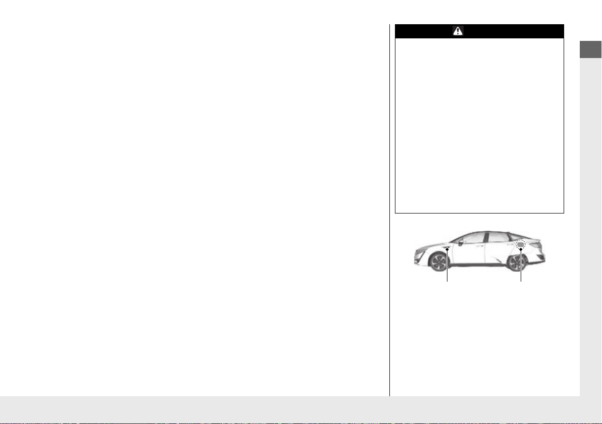
Quick Reference Guide
Hydrogen
Ventilation Duct
(Above the both
front tires)
Hydrogen
Ventilation Duct
(Inside the fuel
lid)
Hydrogen Leak Detection System
When the power mode is turned to ON, the hydrogen leak detection system is activated. If a
hydrogen gas leak is detected by the hydrogen detector, the hydrogen leak indicator will
come on.
2 Hydrogen Leak Indicator (P88)
Hydrogen Supply/High Voltage Shut-off System
If the FC system is on and the vehicle is involved in a crash, depending on the severity of the
impact, the shut-off system will cut off the supply of hydrogen and electricity. In this case, it
is not possible to restart the vehicle.
To restart the FC system, consult an authorized Honda Clarity Fuel Cell dealer.
WARNING
Do not block the hydrogen ventilation
ducts.
The hydrogen tanks, FC stack, and
hydrogen supply components have
ventilation ducts to allow any leaked
hydrogen to escape into the atmosphere. If
the opening of a duct is blocked with snow,
leaves, etc., and a hydrogen leak occurs, the
leaked gas can make its way into the motor
room, where it can ignite, resulting in a fire
or explosion.
Make sure the ducts are free of any
obstructions before activating the power
system.
Do not remove or disassemble a hydrogen
duct: Doing so can lead to a fire or
explosion if a hydrogen gas leak occurs.
15

Quick Reference Guide
Hydrogen Gas Leak
If a hydrogen gas leak is suspected, follow the recommended actions listed in the
instructions of this owner’s manual.
2 If Hydrogen Gas is Leaking (P487)
WARNING
Since hydrogen gas is highly flammable, a
hydrogen gas leak is extremely dangerous
as the leaked gas, which is dispersed into
the atmosphere, can ignite, resulting in a
fire in which you or someone else can be
serious injured or killed. Keep flammable
materials and liquids away from the vehicle
at all times, especially if a hydrogen gas
leak is detected.
In the case of a hydrogen gas leak, a buzzer
will sound and the hydrogen gas leak
indicator will come on. If you are driving
the vehicle, stop in a safe, well-ventilated
place. Then turn the power mode to OFF
and contact an authorized Honda Clarity
Fuel Cell dealer at once. You should also
display signs warning of the danger and be
aware of and keep away anything that
could ignite the gas.
The system is designed so that in the event
that the vehicle catches fire, the gas inside
the tanks will be released through the tank
valves, thereby ensuring that pressure (due
to heat from the fire) within the tanks does
not build up.
16
This gas is released toward the rear of the
vehicle in a downward direction. Do not
attempt to extinguish the fire from behind
the vehicle as the exiting gas may ignite
into a flame.
Quick Reference Guide
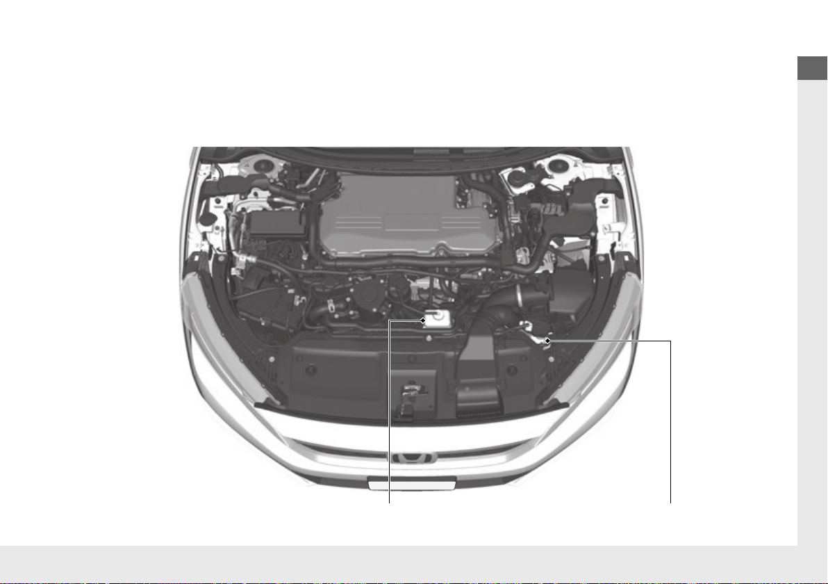
FC Insulating Fluid Reserve TankInverter Coolant Reserve Tank
Fuel Cell Insulating Fluid
Fuel cell insulating fluid (FC insulating fluid) uses a specifically designed fluid with high electrical insulation properties in order to safely cool
the fuel cell.
Never add water, other commercial coolants, or genuine Honda inverter coolant to the cooling system. Doing so will cause damage to the
fuel cell.
Consult an authorized Honda Clarity Fuel Cell dealer to replenish or change the fuel cell insulating fluid.
17
Quick Reference Guide
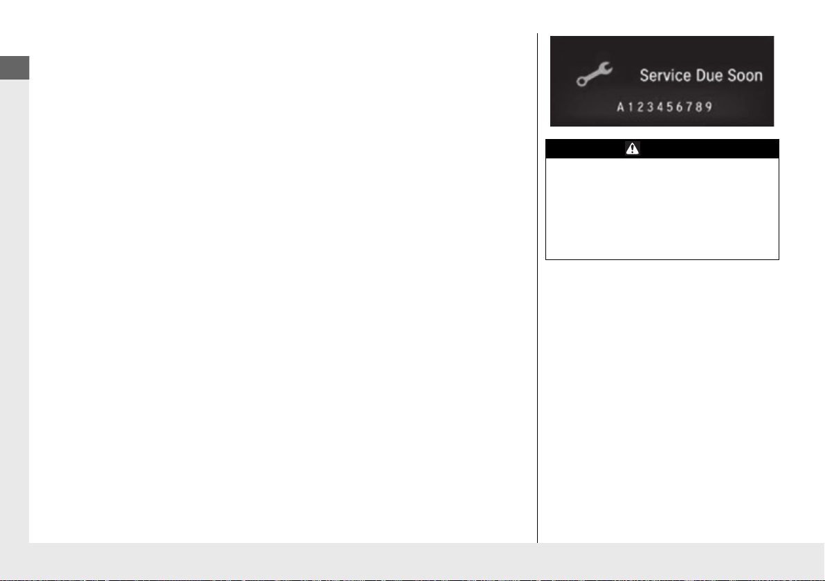
Ion Exchanger
An ion exchanger is installed in the fluid lines for the fuel cell in order to maintain the
insulation properties of the fuel cell insulating fluid (FC insulating fluid).
If the message Service Due Soon A appears on the driver information interface, ion
exchange filter replacement is necessary. Be sure to consult an authorized Honda Clarity
Fuel Cell dealer.
2 Indicators (P87)
Exhaust Pipe
Water is expelled from the tail pipe while the vehicle is running or while the High Voltage
battery is being charged. This also happens after the vehicle has been running or when you
shut down the FC system by setting the power mode to OFF. If you stand to the left rear of
the vehicle, you may be sprayed by this waste water.
Never drink water expelled from the pipe. Though this water is harmless, it is not suitable
for drinking.
While the vehicle is parked during cold temperatures, the FC system may automatically turn
on and discharge water from the exhaust pipe. If this water is discharged as a vapor, it may
appear as a white mist. This, however, is not indicative of a problem.
Do not obstruct or block the exhaust pipe as the FC system may stop working.
Maintenance, Repair, and Disposal
Always consult an authorized Honda Clarity Fuel Cell dealer regarding maintenance, repair,
and disposal.
Fuel cells and High Voltage batteries that have been removed from disposed vehicles are
collected through authorized Honda Clarity Fuel Cell dealers. Do not dispose of those
batteries yourself.
WARNING
Do not directly touch any water emissions
from the exhaust pipe.
Water created during FC power generation
is discharged from the exhaust pipe in the
form of either liquid (water) or gas (steam).
Directly touching this water may cause
burns.
18

Quick Reference Guide
In Case of a Crash
● If a vehicle fire occurs, leaked hydrogen gas may ignite. Stay far away from the vehicle
and call the local fire department.
To extinguish a vehicle fire, use a large amount of water, dry chemical fire extinguisher
(Class A, B, or C), or carbon dioxide fire extinguisher. With an inadequate amount of
water, a fire cannot be put out completely. Never attempt to extinguish a vehicle fire
with a small amount of water.
● If your vehicle needs to be towed, make sure it is done with all the wheels lifted using the
flat bed equipment. If the front wheels are touching the ground, the rotating tires will
force the electric motor to spin, which in turn, may damage the power system,
transmission, etc.
WARNING
If the body of the vehicle is seriously
damaged or deformed in a crash, hydrogen
gas may leak out from the vehicle. Keep
flammable sources, such as a lit cigarette or
warning flares, away from the vehicle.
2 If Hydrogen Gas is Leaking (P487)
Also, high voltage parts and/or the cables
(orange) connecting them may be exposed
as a result of a crash. Stay clear of these
parts as you may be electrocuted.
If the vehicle catches fire, leaked hydrogen
gas may ignite. Stay far away from the
vehicle and report to the fire department
that a vehicle containing hydrogen tanks is
on fire.
The system is designed so that in the event
that the vehicle catches fire, the gas inside
the tanks will be released through the tank
valves, thereby ensuring that pressure
within the tanks does not build up. This gas
is released toward the rear of the vehicle in
a downward direction. Do not attempt to
extinguish the fire from behind the vehicle
as the exiting gas may ignite into a flame.
19

Quick Reference Guide
WARNING
If a High Voltage battery fluid leaks, be
careful not to touch the fluid. It can harm
your eyes and skin. If it comes in contact
with your eyes and skin; flush the affected
area with clean water immediately for a
few minutes, and seek immediate medical
attention.
Do not use a warning flare near a fuel cell
vehicle. If hydrogen gas is leaking, it may
ignite the gas, and result in a vehicle fire.
20

Quick Reference Guide
Regenerative Energy and Regenerative Braking
When decelerating or while driving downhill, the electric motor acts as a generator that recover a portion of the electrical energy that was
used to accelerate the vehicle.
In the following situations, the vehicle generates electricity while decelerating.
● The accelerator pedal is released with the gear position in
● The brake pedal is depressed with the gear position in
u When the High Voltage battery is fully charged or its temperature is too cold/hot, or another factor or factors are effecting the
condition of the battery, the regenerative braking system may not be activated.
(D
(D
.
.
21
Quick Reference Guide
Eco Assist® System
Blue Green BlueBlue-Green
Aggressive Deceleration Moderate
Deceleration
Fuel-Efficient Driving Moderate
Acceleration
Aggressive Acceleration
Ambient Meter
● Changes color to reflect how fuel-efficiently you are driving.
Green: Slow acceleration or deceleration (good fuel economy)
White-green: Moderate acceleration or deceleration (moderate fuel economy)
White: Aggressive acceleration or deceleration (poor fuel economy)
● The indicator remains red as long as SPORT mode is activated.
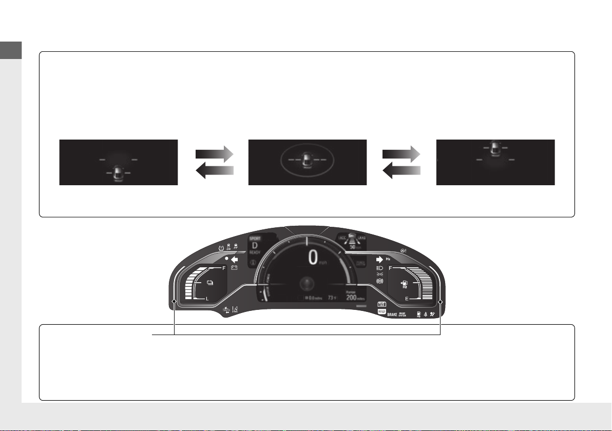
Eco Drive Display
The vehicle icon in the display moves forward and back and the background color changes to indicate how fuel-efficiently you are driving.
● When you accelerate and decelerate, the icon moves forward and back respectively. The greater the acceleration or deceleration, the
greater the icon moves.
● When the icon moves too far in one direction, the screen changes from green to blue to indicate that you are driving inefficiently.
● You can maintain better fuel efficiency by keeping the icon in the center.
Blue-Green
22
Quick Reference Guide
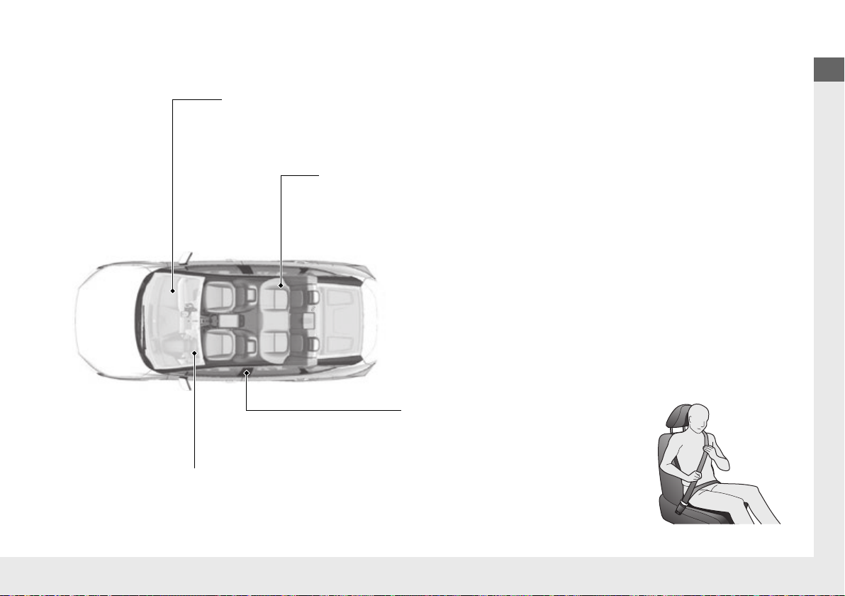
Airbags
(P 53)
● Your vehicle is fitted with airbags to help protect you and
your passengers during a moderate-to-severe collision.
Child Safety
(P 68)
● All children 12 and younger should be seated in the rear seat.
● Smaller children should be properly restrained in a forward-facing child seat.
● Infants must be properly restrained in a rear-facing child seat.
Before Driving Checklist
(P 45)
● Before driving, check that the front seats, head restraints,
steering wheel, and mirrors have been properly adjusted.
Seat Belts
(P 46)
● Fasten your seat belt and sit upright well
back in the seat.
● Check that your passengers are wearing
their seat belts correctly.
Fasten your lap belt as
low as possible.
Safe Driving
(P 41)
23
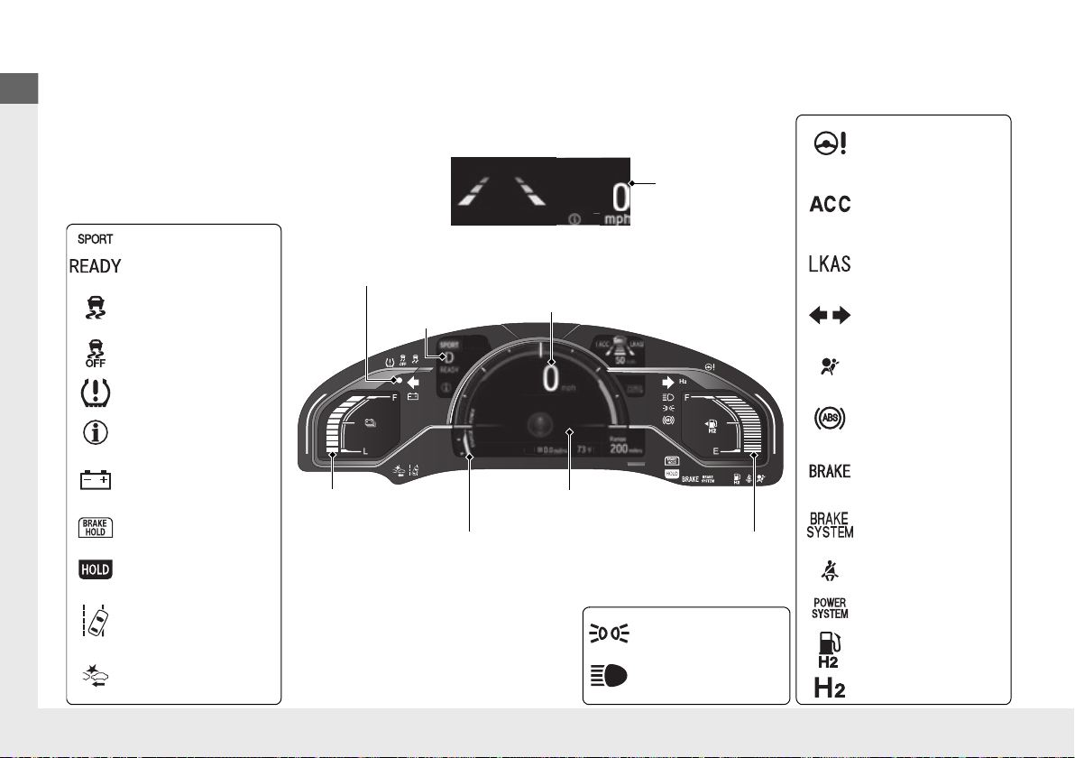
Quick Reference Guide
Instrument Panel
Lights On Indicator
System Indicators
12-Volt Battery
Charging System
Indicator
Anti-lock Brake
System (ABS)
Indicator
Vehicle Stability Assist
(VSA®) System
Indicator
VSA® OFF Indicator
Electric Power
Steering (EPS)
System Indicator
Lights Indicators
High Beam Indicator
Seat Belt Reminder
Indicator
System Indicators
System Message
Indicator
Parking Brake and
Brake System
Indicator (Red)
Supplemental
Restraint System
Indicator
Gauges
(P 114)
/Driver Information Interface
(P 117)
/
Head-Up Display
(P 125)
/System Indicators
(P 84)
Low Tire Pressure/
TPMS Indicator
Turn Signal and
Hazard Warning
Indicators
Speedometer
Automatic Brake Hold
System Indicator
Parking Brake and
Brake System
Indicator (Amber)
SPORT Mode Indicator
Collision Mitigation
Brake System
TM
(CMBS
TM
) Indicator
Road Departure
Mitigation (RDM)
Indicator
Immobilizer System Indicator/
Security System Alarm Indicator
Automatic Brake Hold
Indicator
Head-Up Display
READY Indicator
POWER SYSTEM
Indicator
Gear Position
Indicator
Fuel Gauge
Driver Information
Interface
High Voltage Battery
Charge Level Gauge
POWER/CHARGE
Gauge
Low Fuel Indicator
Hydrogen Leak
Indicator
Adaptive Cruise
Control (ACC) with
Low Speed Follow
(LSF) Indicator
Lane Keeping Assist
System (LKAS)
Indicator
24
(P 83)
Quick Reference Guide
Controls
4
3
Turn Signal Control Lever
Right
Left
Light Control Switches
Low Beam
High Beam
Flashing
(P 129)
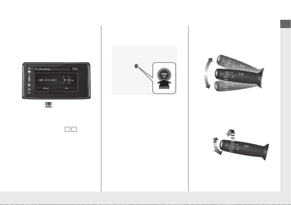
The navigation system receives signals from
GPS satellites, updating the clock
automatically.
You can also adjust the time manually.
a
Select the (Home) icon, then select
Settings.
b
Select Clock, then Clock Adjustment.
c
Touch the respective / icon to
adjust the hours or minutes up or
down.
d
Select OK.
Clock
(P 130)
POWER Button
Press the button to changes the vehicle’s
power mode.
(P 151)
Turn Signals
Lights
(P 155)
(P 154)
25
Quick Reference Guide
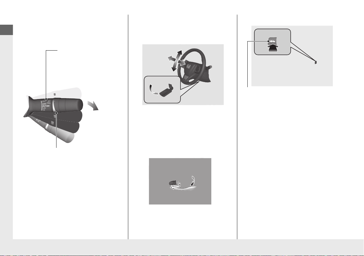
Wipers and Washers
Wiper/Washer Control Lever
Adjustment Ring
(-
: Low Sensitivity
(+
: High Sensitivity
MIST
OFF
AUTO: Wiper speed varies
automatically
LO: Low speed wipe
HI: High speed wipe
Pull toward
you to spray
washer fluid.
Trunk Opener
(P 159)
Steering Wheel
● To adjust, push the adjustment lever
down, adjust to the desired position, then
lock the lever back in place.
(P 166)
Trunk
(P 143)
26
Unlocking the Front
Doors from the Inside
(P 140)
● Pull either front door inner handle to
unlock and open it in one motion.
● Unlocking and opening the driver’s door
from the inner handle unlocks all the
other doors.
● To unlock and open the trunk:
• Press the trunk opener on the driver’s
door.
• Press the trunk release button on the
smart entry remote.
• Press the trunk release button on the
trunk lid.
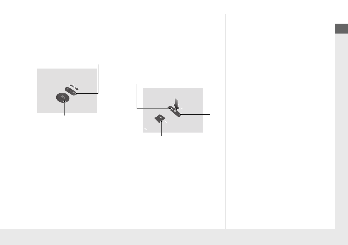
Quick Reference Guide
Selector Switch
Adjustment Switch
Power Window Lock Button
Window Switch
Indicator
Power Door Mirrors
(P 168)
● With the power mode in ON, move the
selector switch to L or R.
● Push the appropriate edge of the
adjustment switch to adjust the mirror.
Power Windows
● With the power mode in ON, open and
close the power windows.
● If the power window lock button is in the
off position, each passenger’s window
can be opened and closed with its own
switch.
● If the power window lock button is in the
on position (indicator on), each
passenger’s window switch is disabled.
(P 149)
27
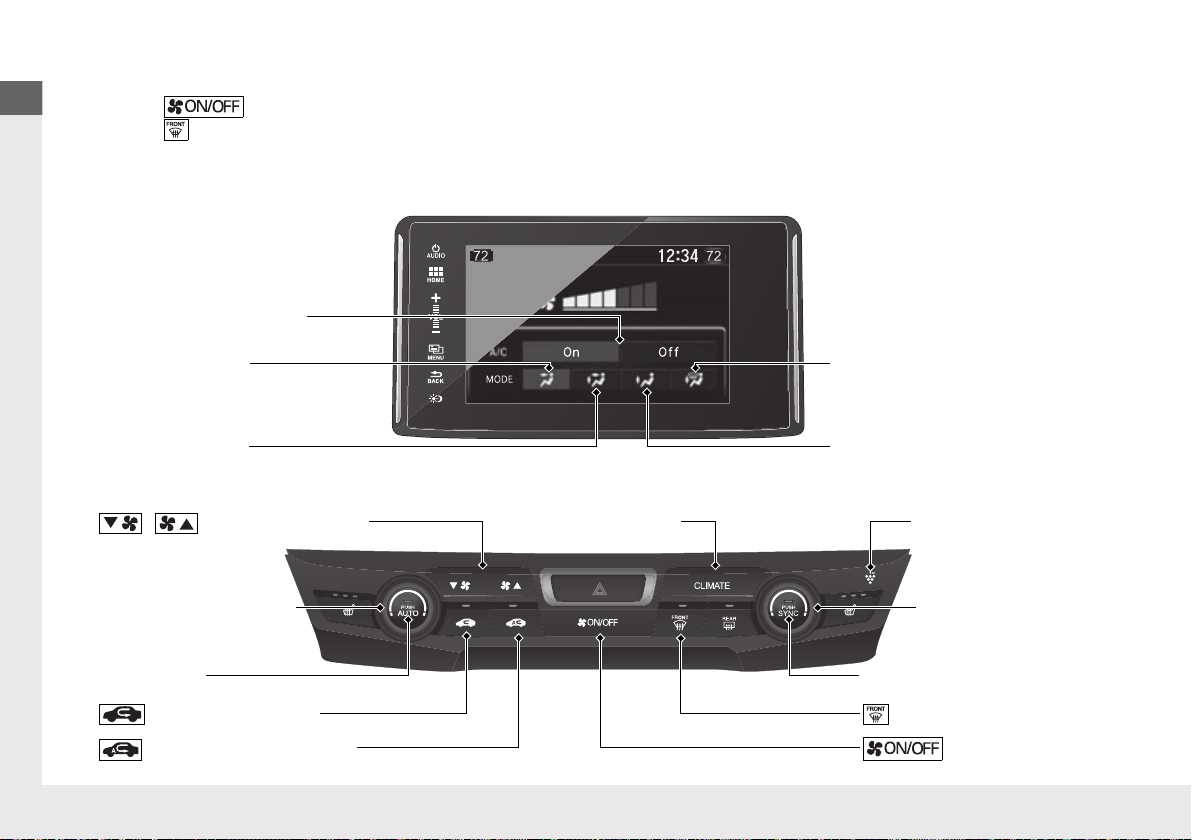
Quick Reference Guide
Climate Control System
AUTO Button
/ (Fan Control) Buttons
MODE Control Icon
(Air flows from floor and dashboard
vents, and back of the center console)
A/C (Air Conditioning) Icon
Plasmacluster Mark
MODE Control Icon
(Air flows from floor and
windshield defroster vents)
MODE Control Icon
(Air flows from floor vents)
Passenger’s Side
Temperature Control Dial
SYNC (Synchronized) Button
(Windshield Defroster) Button
(ON/OFF) Button
(Recirculation) Button
(Auto Recirculation) Button
MODE Control Icon
(Air flows from dashboard vents
and back of the center console)
Driver’s Side Temperature
Control Dial
CLIMATE Button
● Press the AUTO button to activate the climate control system.
● Press the button to turn the system on or off.
● Press the button to defrost the windshield.
The climate control system is voice operable. (P228)
(P 185)
28
 Loading...