

Honda CB500T User Manual

Il
111. INSPECTION AND ADJUSTMENT
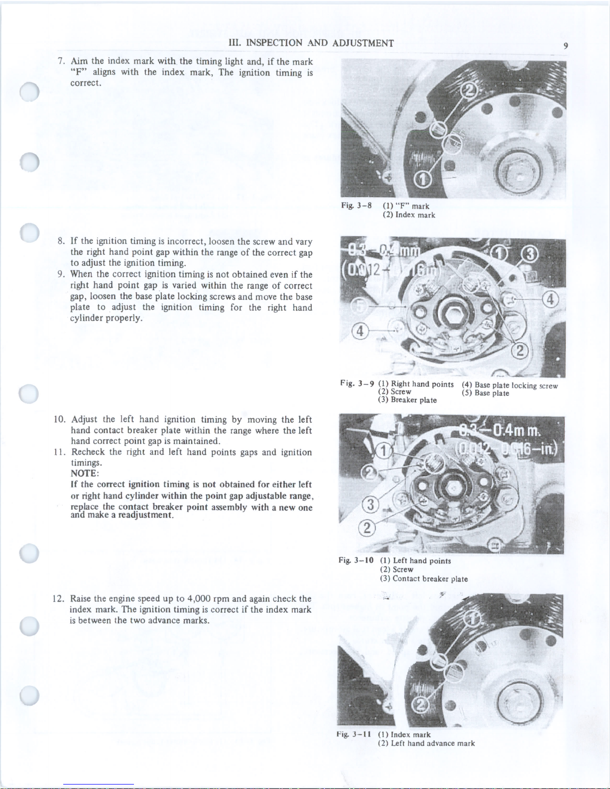
8. Adjust the synchronization so the right and left throttle
valve will both move the same amount when the throttle
grip is moved slightly.
The adjustment can be made by turning the throttle cable
adjuster.
NOTE:
Upon adjustment, tighten the lock nut securely and snap
the throttle grip three or four times to recheck the
synchronization.
9. After completing the adjustment, check and adjust the free
play of the throttle grip.
lO. Remove the vacuum gauges and install the plugs and fuel
tank.
Fig. 3-16 (1) Cable adjuster
(2) Lock nut
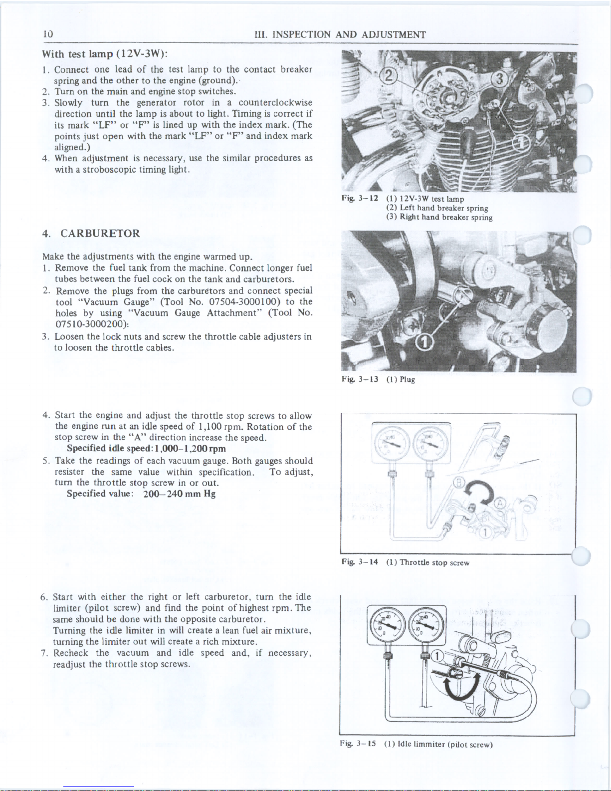
5. THROTTLE CABLE
Check the free play of the throttle grip. It should be 1.3-2
mm (0.04-0.08 in.) at the throttle grip flange or 10-15
deg. of the grip rotation.
To adjust, loosen the lock nut and tum the grip play
adjuster either in or out as necessary. Tum the adjuster in
the direction " A" to decrease the play, or "B" to increase
it.
Fig. 3-17
(1) Lock nut
(2) Grip play adjuster
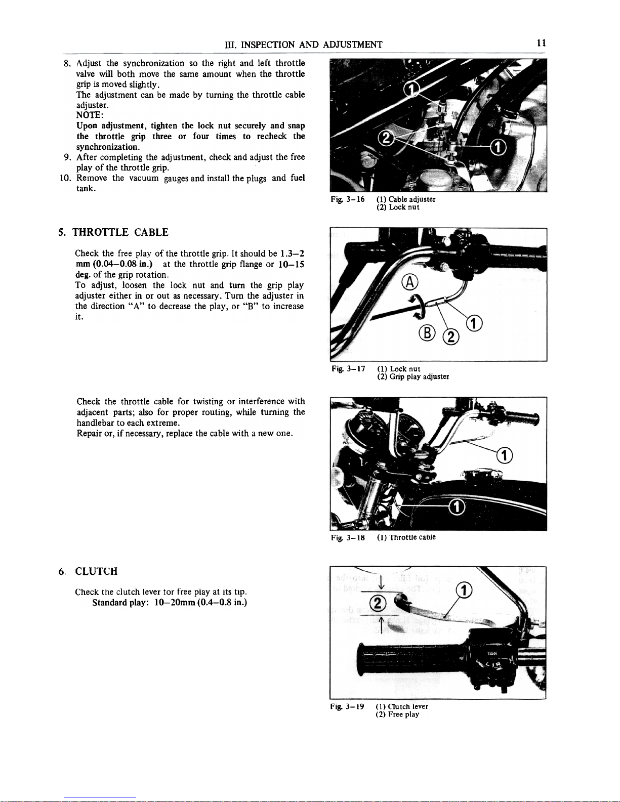
Check the throttle cable far twisting or interference with
adjacent parts; also far proper routing, while tuming the
handlebar to each extreme.
Repair or, if necessary, replace the cable wi th a new one.
(1) Throttle cable
Fig. 3-18
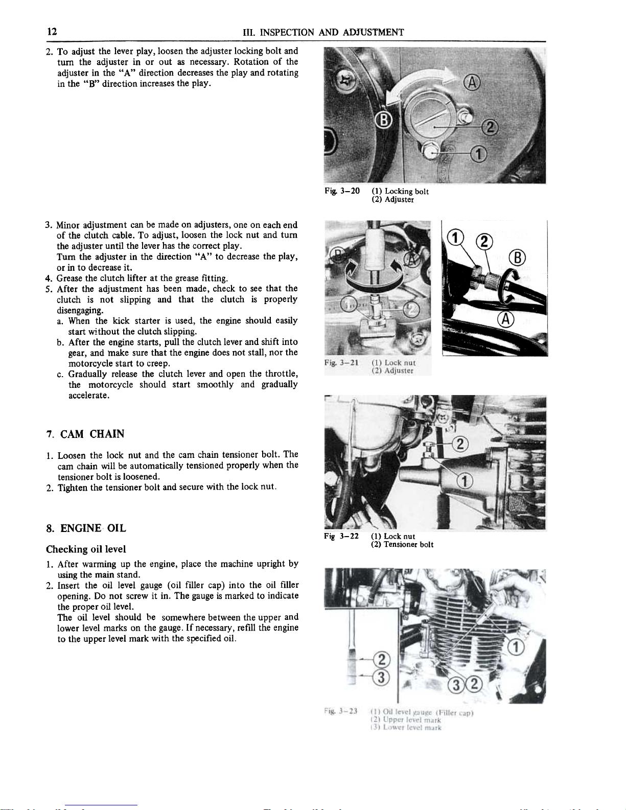
CLUTCH
6.
Check the clutch lever for free play at its tIpo
Standard play: 10-20mm (0.4-0.8 in.)
Fig. 3-19
(I) Clutch lever
(2) Free play
12
111. INSPECTION AND ADJUSTMENT
2. To adjust the lever play, loosen the adjuster locking bolt and
turo the adjuster in or out as necessary. Rotation of the
adjuster in the "A" direction decreases the play and rotating
in the "B" direction increases the play.
Fig. 3-20
(1) Locking bolt
(2) Adjuster
@
@
3. Minor adjustment can be made on adjusters, one on each e~d
of the clutch cable. To adjust, loosen the lock nut and tUffi
the adjuster until the lever has the correct play.
Tuffi the adjuster in the direction "A" to decrease the play,
or in to decrease it.
4. Grease the clutch lifter at the grease fitting.
5. After the adjustment has been made, check to see that the
clutch is not slipping and that the clutch is properly
disengaging.
a. When the kick starter is used, the engine should easily
start without the clutch slipping.
b. After the engine starts, pull the clutch lever and shift into
gear, and rnake sure that the engine does not stall, nor the
motorcycle start to creep.
c. Gradually release the clutch lever and open the throttle,
the motorcycle should start smootWy and gradually
accelerate.
7. CAM CHAIN
1. Loosen the Iock nut and the cam chain tensioner boit. The
cam chain will be automatically tensioned properly when the
tensioner bolt is loosened.
2. Tighten the tensioner bolt and se cure with the Iock fiuto
8. ENGINE OIL
Fig 3-22
(1) Lock nut
(2) Tensioner bolt
Checking oillevel
1. After warming up the engine, pIace the machine upright by
using the main stando
2. Insert the oil level gauge (oil filler cap) in to the oil filler
opening. Do not screw it in. The gauge is marked to indicate
the proper oillevel.
The oil level should be somewhere between the upper and
lower level marks on the gauge. If necessary, refill the engine
to the upper level mark with the specified oil.
13
III. INSPECTION AND ADJUSTMENT
Changing oil
1. After warming up the engine, turo the main switch to "OFF"
and remove the oil fùler cap.
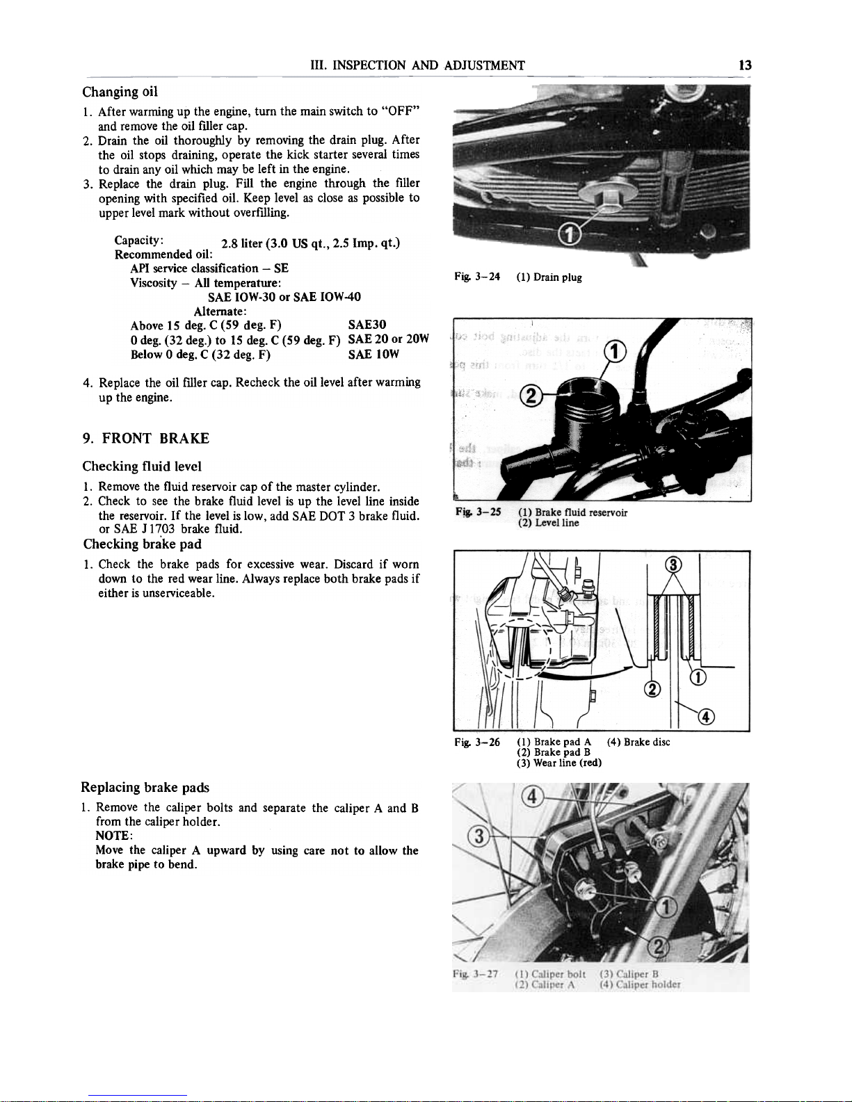
2. Drain the oil thorouglùy by removing the drain plug. After
the oil stops draining, operate the kick starter several times
to drain any oil which may be left in the engine.
3. Replace the drain plug. FilI the engine through the filler
opening with specified oil. Keep level as close as possible to
upper level mark without overfùling.
Fig. 3- 24
(1) Drain plug
Capacity: 2.8 liter (3.0 US qt., 2.5 Imp. qt.)
Recommended oil:
API service classification -SE
Viscosity -Ali temperature:
SAE IOW-30 or SAE IOW-40
Alternate:
Above 15 deg. C (59 deg. F) SAE30
O deg. (32 deg.) to 15 deg. C (59 deg. F) SAE 20 or 20W
Below O deg. C (32 deg. F) SAE 10W
4. Replace the oil rùler cap. Recheck the oillevel after warming
up the engine.
9. FRONT BRAKE
Checking fluid level
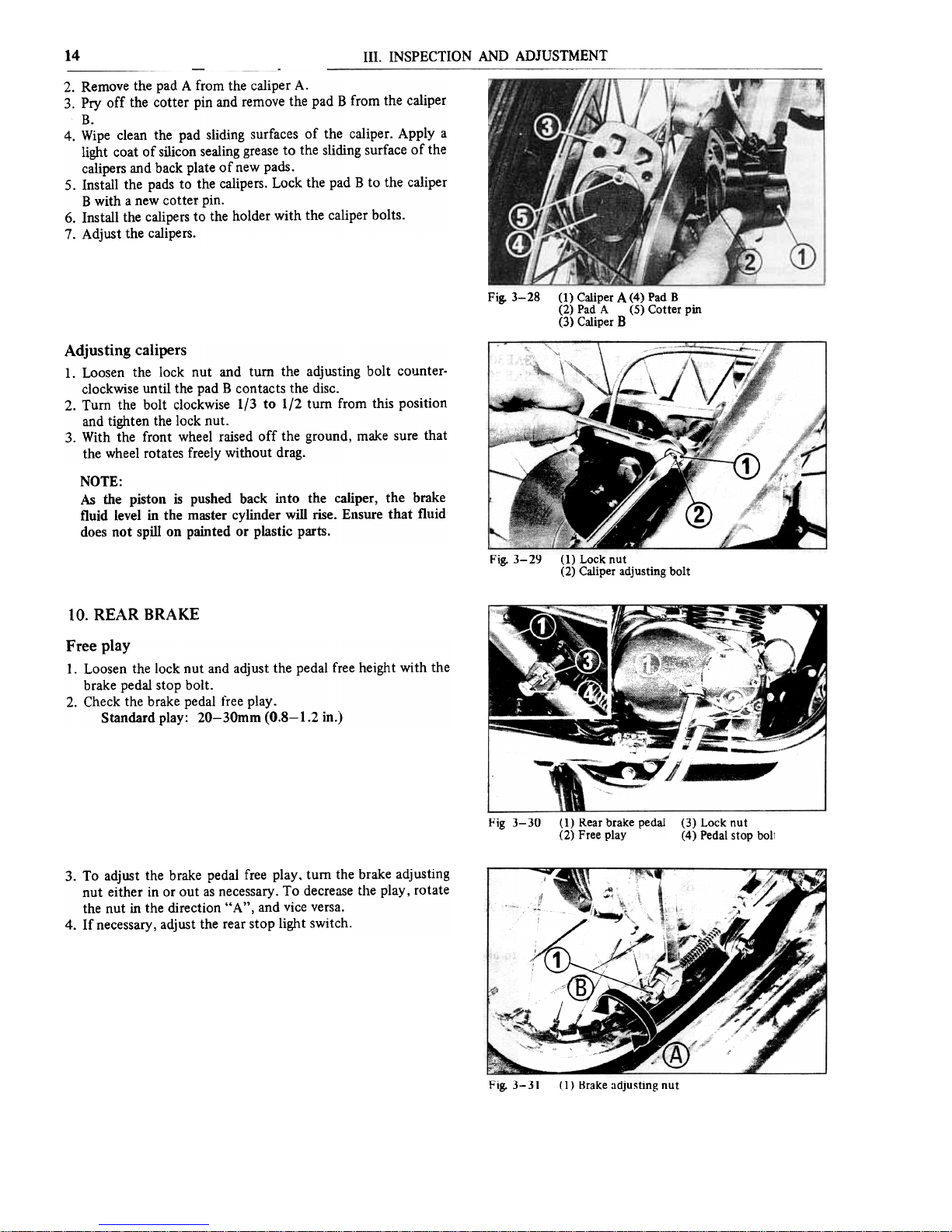
l. Remove the fluid reservoir cap of the master cylinder.
2. Check to see the brake fluid level is up the levelline inside
the reservoir. If the level is low, add SAE DOT 3 brake fluido
or SAE J 1703 brake fluido
Checking brake pad
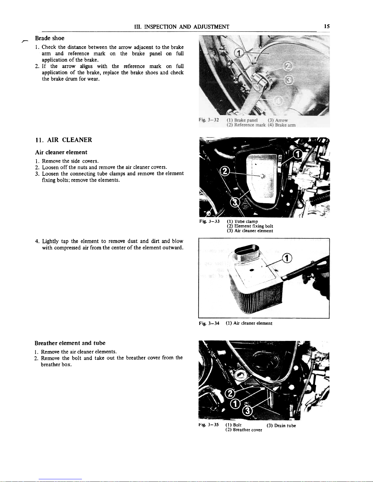
lo Check the brake pads for excessive wearo Discard if worn
down to the red wear line. Always re pIace both brake pads if
either is unserviceable.
Fig. 3- 26
(4) Brake disc(1) Brake pad A
(2) Brake pad B
(3) Wear line (red)
Replacing brake pads
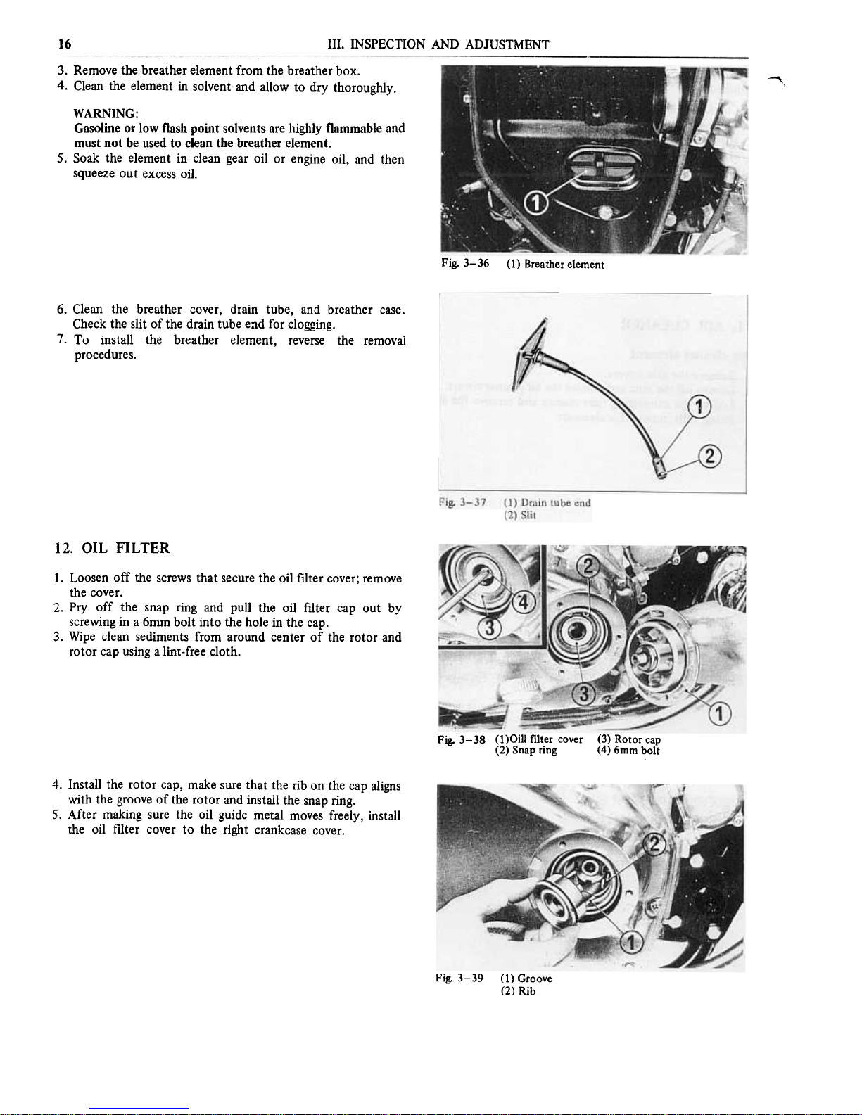
l. Remove the caliper bolts and separate the caliper A and B
[rom the caliper holder.
NOTE:
Move the caliper A upward by using care not to aIlow the
brake pipe to bendo
14
111. INSPECTION AND ADJUSTMENT
2. Remove the pad A from the caliper A.
3. Pry off the cotter pin and remove the pad B from the caliper
B.
4. Wipe clean the pad sliding surfaces of the caliper. Apply a
light coat of silicon sealing grease to the sliding surface of the
calipers and back plate of new pads.
5. lnstall the pads to the calipers. Lock the pad B to the caliper
B with a new cotter pino
6. lnstall the calipers to the holder with the caliper bolts.
7. Adjust the calipers.
Fig. 3-28
(1) Caliper A (4) Pad B
(2) Pad A (5) Cotter pin
(3) Caliper B
Adjusting calipers
1. Loosen the lock nut and tum the adjusting bolt COI.lnterclockwise until the pad B contacts the disco
2. Tum the bolt clockwise 1/3 to 1/2 tum from this position
and ti~ten the lock fiuto
3. With the front wheel raised off the ground, make sure that
the wheel rotates freely without drago
NOTE:
As the piston is pushed back into the caliper, the brake
fluid level in the master cylinder wiIl rise. Ensure that fluid
does not spiII on painted or plastic parts.
flig. 3-29 (1) Lock nut
(2) Caliper adjusting bolt
lO. REAR BRAKE
Free play
l. Loosen the \ock nut and adjust the pedal [ree height with the
brake perla! stop bolt.
2. Check the brake pedal t'ree p\ay.
Standard p\ay: 20-30mm (0.8-1.2 in.)
Fig 3- 30 (l) Rear brake pedal
(2) Free play
(3) Locknut
(4) Pedal stop boll
3. To adjust the brake pedal free play. turo the brake adjusting
nut either in or out as necessary. To decrease the play, rotate
the nut in the direction "A", and vice versa.
4. If necessary, adjust the rear stop light switch.
Fig. 3-31
(1) Brake adjusting nut
III. INSPECTION AND ADJUSTMENT
15
~
Brade shoe
l. Check the distance between the arrow adjacent to the brake
arm and reference mark on the brake panel on Culi
application of the brake.
2. If the arrow aligtls with the reference mark on Culi
application of the brake, replace the brake shoes a.,d check
the brake drum far wear.
Il. AIR CLEANER
Air cleaner element
1. Remove the side covers.
2. Loosen off the nuts and remove the air cleaner covers.
3. Loosen the connecting tube clamps and remove the element
fixing bolts; remove the elements.
t'1g. 3-33
(1) Tube clamp
(2) Element fixing bolt
(3) Air cleaner element
4. Lightly tap the element to remove dust and dirt and blow
with compressed air from the center of the element outward.
Fig. 3-34
(1) Air cleaner element
Breather element and tube
l. Remove the air cleaner elements.
2. Remove the bolt and take out the breather cover from the
breather box.
tolg. 3-35
(1) Dolt
(2) Breather cover
(3) Drain tube
16 111. INSPECTION AND ADJUSTMENT
~,
3. Remove the breather element [rom the breather box.
4. Clean the element in solvent and allow to dry thorougWy.
WARNING:
Gasoline or low flash point solvents afe highly flammable and
must not be used to clean the breather elemento
5. Soak the element in clean gear oil or engine oil, and then
squeeze out excess oil.
Fig. 3-36
(1) Breather element
6. Clean the breather cover, drain tube, and breather case.
Check the slit of the drain tube e;ld far clogging.
7. To install the breather element, reverse the removal
procedures.
12. OIL FILTER
1. Loosen off the screws that se cure the oil filter cover; remove
the cover.
2. Pry off the snap ring and pull the oil filter cap out by
screwing in a 6mm bolt into the hole in the cap.
3. Wipe clean sediments from around center of the rotar and
rotar cap using a lint-free cloth.
Fig. 3-38 (l)Oill filter cover (3) Rotor cap
(2) Snap ring (4) 6mm bolt
4. lnstall the rotar cap, make sure that the rib on the cap aligns
with the groove of the rotar and install the snap fingo
5. After making sure the oil guide metal moves freely, install
the oil filter cover to the right crankcase cover o
1'1g. 3-39 (1) Groove
(2) Rib
111. INSPECTION AND ADJUSTMENT
17
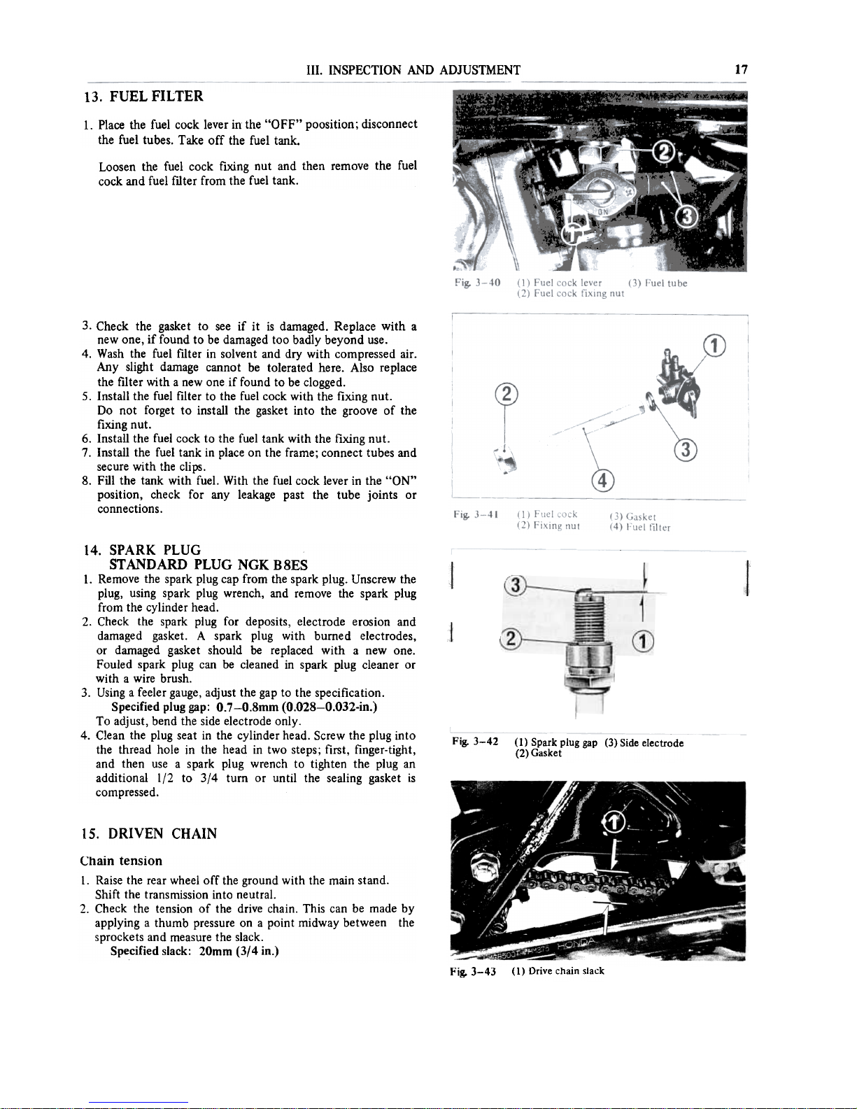
13. FUEL FILTER
l. PIace the fuel cock Iever in the "OFF" poosition; disconnect
the fuel tubes. Take off the fuel tank.
Loosen the fuel cock fixìng nut and then remove the fuel
cock and fuel fllter from the fuel tank.
3. Check the gasket to see if it is darnaged. Replace with a
new alle, if found to be damaged too bad1y beyond use.
4. Wash the fuel fllter in solvent and dry with compressed air.
Any slight darnage cannot be tolerated here. Aiso replace
the filter with a new oneif found to be clogged.
5. lnstall the fuel filter to the fuel cock with the fixing fiuto
Do not forget to install the gasket into the groove of the
fixing fiuto
6. lnstall the fuel cock to the fuel tank with the flxing fiuto
7. lnstall the fuel tank in pIace on the frame; connect tubes and
secure with the clips.
8. FilI the tank with fuel. With the fuel cock lever in the "aN"
position, check far any leakage past the tube joints or
connections.
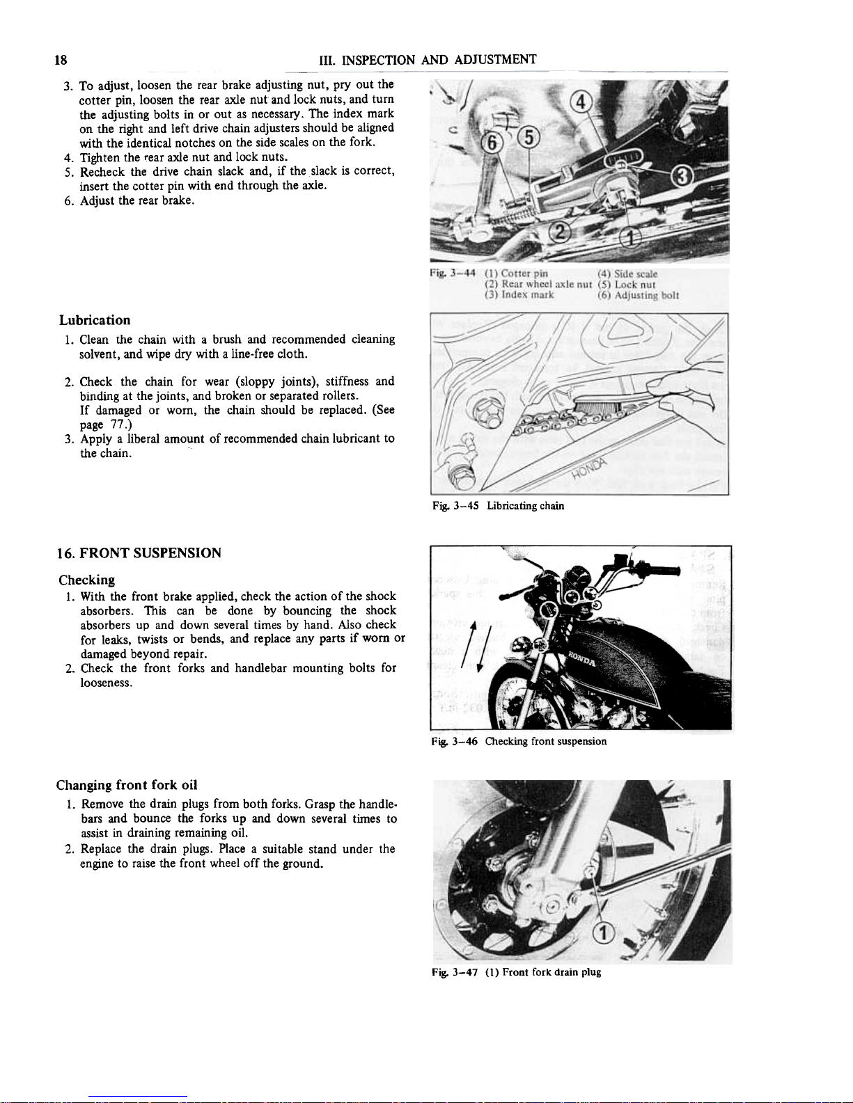
14. SPARK PLUG
STANDARD PLUG NGKB8ES
1. Remove the spark plug cap from the spark plug. Unscrew the
plug, using spark plug wrench, and remove the spark plug
from the cylinder head.
2. Check the spark plug far deposits, electrode erosion and
damaged gasket. A spark plug with burned electrodes,
or darnaged gasket should be replaced with a new one.
Fouled spark plug can be cleaned in spark plug cleaner or
with a wire brush.
3. Using a feeler gauge, adjust the gap to the specification.
Specified plug gap: O.7-0.8mm (O.O28-0.032-in.)
To adjust, bend the side electrode only.
4. Clean the plug seat in the cylinder head. Screw the plug into
the thread hole in the head in two steps; first, finger-tight,
and then use a spark plug wrench to tighten the plug an
additional 1/2 to 3/4 turo or until the sealing gasket is
compressed.
Fig. 3-42
(l) Spark plug gap (3) Side electrode
(2) Gasket
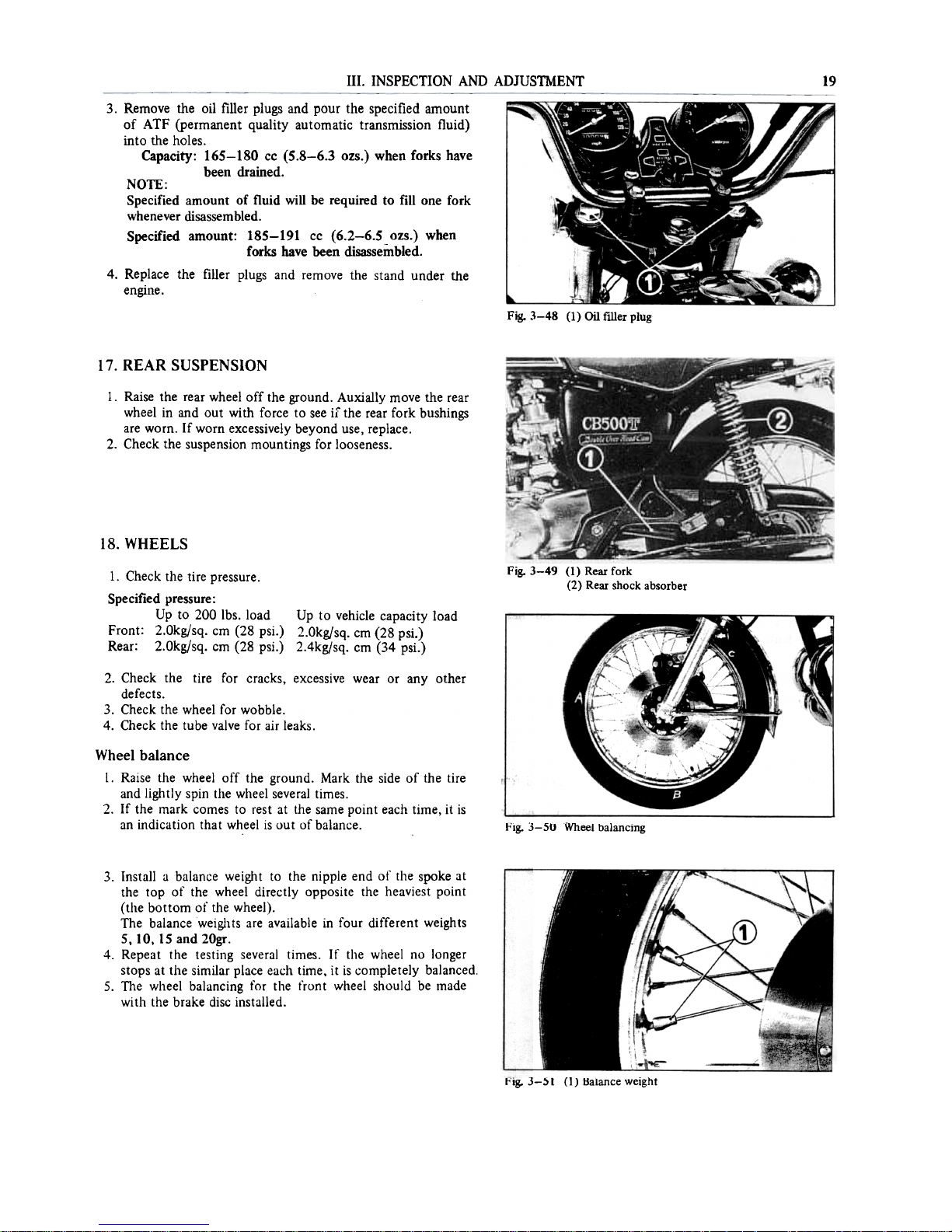
15. DRIVEN CHAIN
Chain tension
l. Raise the rear wheel off the ground with the main stando
Shift the transmission into neutral.
2. Check the tension of the drive chain. This can be made by
applying a thumb pressure on a point midway between the
sprockets and measure the slack.
Specified slack: 20mm (3/4 in.)
Fig. 3-43 (1) Olive chain slack
111. INSPECTION AND ADJUSTMENT
18
3. To adjust, loosen the rear brake adjusting nut, pry out the
cotter pin, loosen the rear axle nut and lock nuts, and tUffi
the adjusting bolts in or out as necessary. The index mark
on the right and left drive chain adjusters should be aligned
with the identical notches on the side scales on the fork.
4. Tighten the ~ear axle nut and lock nuts.
5. Recheck the drive chmn slack and, if the slack is correct,
insert the cotter pin with end through the axle.
6. Adjust the rear brake.
Lubrication
1. Clean the chain with a brush and recommended cleaning
solvent, and wipe dry with a line-free cloth.
2. Check the chain far wear (sloppy joints), stiffness and
binding at the joints, and broken or separated rollers.
If damaged or wom, the chain should be replaced. (See
page 77.)
3. Apply a liberaI amount of recommended chain lubricant to
the chain.
Fig. 3-45 Libricating chain
16. FRONT SUSPENSION
Checking
l. With the front brake applied, check the action of the shock
absorbers. This can be done by bouncing the shock
absorbers up and down several times by hand. Also check
far leaks, twists or bends, and re pIace any parts if wom or
damaged beyond repair.
2. Check the front forks and handlebar mounting bolts far
looseness.
Fig. 3-46 Checking front suspension
Changing front fork oil
l. Remove the drain plugs from both forks. Grasp the handle-
bars and bounce the forks up and down several tirnes to
assist in draining remaining oil.
2. Replace the drain pIugs. PIace a suitabie stand under the
engine to raise the front wheel off the ground.
Fig. 3-47 (I) Front forI< drain plug
111. INSPECTION AND ADJUSTMENT
19
3. Remove the oil filler plugs and pour the specified amount
of ATF (permanent quality automatic transmission fluid)
into the holes.
Capacity: 165-180 cc (5.8-6.3 ozs.) when forks bave
been drained.
NOTE:
Specified amount of tluid will be required to fin one fork
whenever disassembled.
Specified amount: 185-191 cc (6.2-6.5 ozs.) when
forks bave been disassembled.
4. Replace the filler plugs and remove the stand under the
engine.
Fig. 3-48 (1) 0i1 filler plug
17. REAR SUSPENSION
l. Raise the rear wheel off the ground. Auxially move the rear
wheel in and out with force to see i[ the rear fork bushings
afe worn. If worn excessively beyond use, replace.
2. Check the suspension mountings far looseness.
18. WHEELS
Fig. 3-49 (1) Rear fork
(2) Rear shock absorber
1. Check the tire pressure.
Specified pressure:
Up to 200 lbs. load Up to vehicle capacity load
Front: 2.0kgjsq. cm (28 psi.) 2.0kg/sq. cm (28 psi.)
Rear: 2.0kgjsq. cm (28 psi.) 2.4kg/sq. cm (34 psi.)
2. Check the tire for cracks, excessive wear or any other
defects.
3. Check the wheel for wobble.
4. Check the tube valve for air leaks.
Wheel balance
l. Raise the wheel off the ground. Mark the side of the tire
and lightly spin the wheel several times.
2. If the mark comes to rest at the same point each time, it is
an indication that wheel is out of balance.
Fig. 3-50 Wheel balancing
3. lnstaii a baiance weight to the nippie end of the spoke at
the top of the wheei directiy apposite the heaviest point
(the bottom of the wheei).
The baiance weights afe avaiiabie in four different weights
5, lO, 15 and 20gr.
4. Repeat the testing severai times. lf the wheei no ionger
stops at the simiiar piace each time, it is compieteiy baianced.
5. The wheei baiancing for the tront wheei shouid be made
with the brake disc instaiied.
l'ISo 3-51 (1) Balance weight

20 111. INSPECTION AND ADJUSTMENT
19. SIOE STANO
1. Check the entire stand assembly (side stand bar, bracket
and rubber pad) for installation, deformation or otherwise
excessive damage.
2. Check the spring for freedom from damage or other
defects.
Fig. 3-52 (1) Side stand bar (4) 6mm bolt
(2) Spring (5) Side stand pivot bolt
(3) Rubber pad
Fig. 3-53 (1) Side stand bar
(2) Spring scale
3. Check the side stand far proper return operation:
a. With the side stand applied, raise the stand off the
ground by using the main stando
b. Attach a spring scale to the lower end of the stand and
measure the force with which the stand is returned to its
originai position.
c. The stand condition is correct if the measurement falls
within 2-3 kg (4.4-6.6Ibs.)
If the stand requires force exceeding the above limit, this
might be due to negiected lubrication, overtightened side
stand pivot bolt, worn stand bar or bracket, or otherwise
excessive tension. Repair as necessary.
4. Check the rubber pad far deterioration or wear.
When the rubber pad wear is excessive so that it is worn
down to the wear line, replace it with a new one.
It is intended that the rubber pad will retum the stand
upon contact with the ground if the stand has been
accidentally left in the down positiòn.
Fig. 3-54 (1) Wear line
Rubber pad replacement
1. Remove the 6mm bolt; separate the rubber pad from the
bracket at the side stando
2. After making sure the coiiar is instaiied, put a new rubber
pad in piace in the bracket with the arrow mark auto
NOTE:
Use rubber pad having the mark "OVER 260 ibs. ONL Y"
3. Secure the rubber pad -vith the 6mm boit.
l''g. 3-55 (I) Rubber pad
(2) Collar
N. ENGINE 21
1. ON-FRAME SERVICING
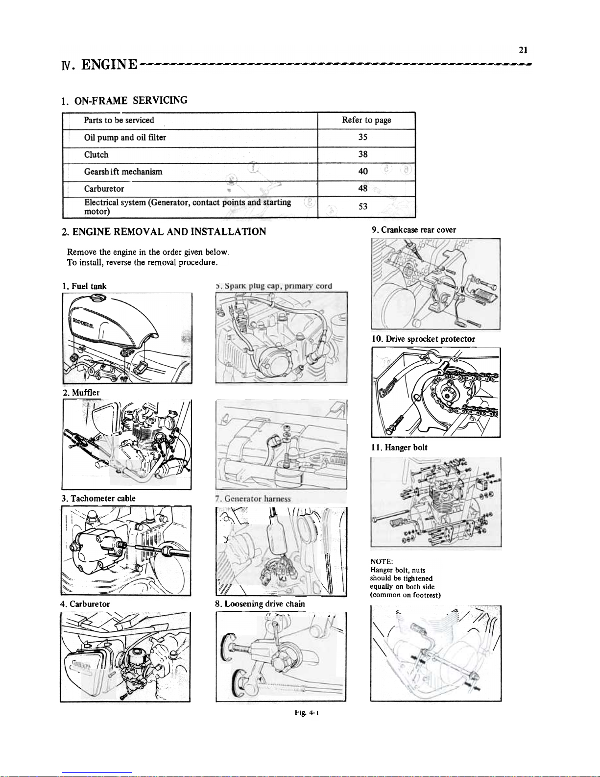
2. ENGINE REMOVAL ANO INSTALLATION
9. Crankcase rear cover
Remove the engine in the arder given below.
To install, reverse the removal procedure.
1. Fuel tank
-
~
1"'-"--""""""
'~
~ ~4I (
r
lO. Drive sprocket protector
~::::::::---~~'.:::-
~
')7;.f\!
.I"
,I
2. Muffler
~"') ""'"
"\~,f/-
~,
1.)/
Il. Hanger bolt
3. Tachometer cable
NOTE:
Hanger bolt, nuts
should be tightened
equal1y on both side
(common on footrest)
8. Loosening drive chain
4. Carburetor
--
~<~
~::~~~~9
1--~
-~
~.
y
~,
,(
f'1g. 4- I
22
IV. ENGINE
3. V AL VE MECHANISM
~
-~
cr
".t'
\\\
f!)
/
/
~~([
;--
--.
~
I').p
~
y
@
,-"
/
@
/
{iffi
~
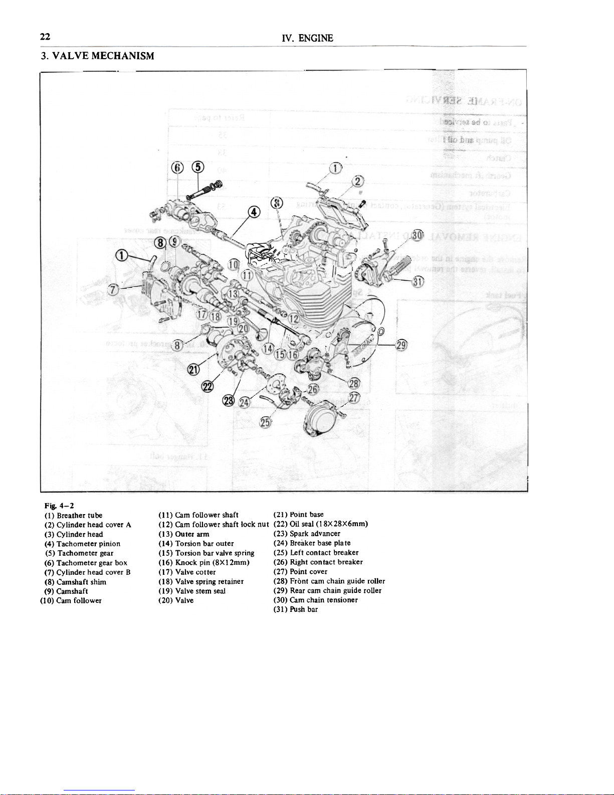
Fig. 4-2
(1) Breather tube
(2) Cylinder head cover A
(3) Cylinder head
(4) Tachorneter pinion
(5) Tachorneter gear
(6) Tachorneter gear box
(7) Cylinder head cover B
(8) Carnshaft shim
(9) Carnshaft
(IO) Caro follower
(11) Cam foUower shaft (21) Point base
(12) Cam foUower shaft lock nut (22) ail seal (18X28X6mm)
(13) Outer arm (23) Spark advancer
(14) Torsion bar outer (24) Breaker base plate
(15) Torsion bar valve spring (25) Left contact breaker
(16) Knock pin (8XI2mm) (26) Right contact breaker
(17) Valve cotter (27) Point cover
(18) Valve spring retainer (28) Frònt cam chain guide roller
(19) Valve stem seal (29) Rear cam chain guide roller
(20) Valve (30) Cam chain tensioner
(31) Push bar
23
IV. ENGINE
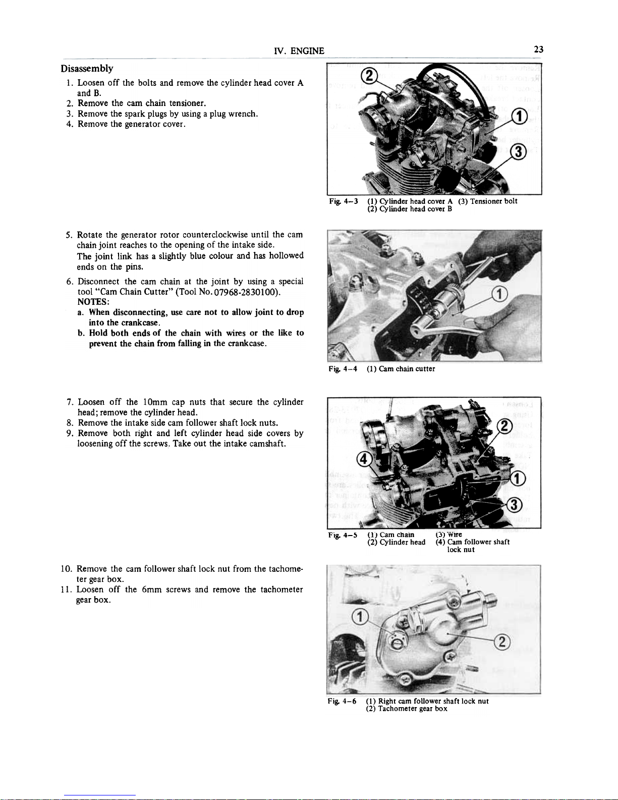
Disassembly
1. Loosen off the bolts and remove the cylinder head cover A
and B.
2. Remove the cam chain tensioner.
3. Remove the spark plugs by using a plug wrench.
4. Remove the generator cover.
Fig. 4-3 (1) Cylinder head cover A (3) Tensioner bolt
(2) Cylinder head cover B
50 Rotate the generator rotor counterclockwise until the cam
chain joint reaches to the opening of the intake sideo
The joint link has a slightly blue colour and has hollowed
ends on the pins.
6. Disconnect the cam chain at the joint by using a special
tool "Cam Chain Cutter" (Tool No. 07968-2830100).
NOTES:
ao When disconnecting, use care not to allo w joint to drop
into the crankcase.
b. Hold both ends of the chain with wires or the like to
prevent the chain from falling in the crankcase.
Fig. 4-4 (1) Cam chain cutter
7. Loosen off the lOmm cap nuts that secure the cylinder
head; remove the cylinder head.
8. Remove the intake side cam follower shaft lock nuts.
9. Remove both right and left cylinder head side covers by
loosening off the screws. Take out the intake camshaft.
l"ìg. 4-5
(1) l:am chatn ljJ wìre
(2) Cylinder head (4) Caro foUower shaft
locknut
lO. Remove the cam follower shaft lock nut from the tachome-
ter gear box.
Il. Loosen off the 6mm screws and remove the tachometer
gear box.
Fig. 4-6 (I) Right caro folIower shaft lock nut
(2) Tachometer gear box
24
N. ENGINE
~
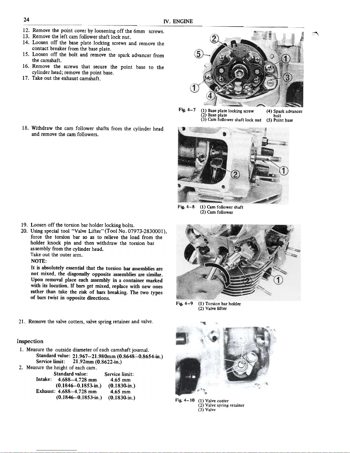
12. Remove the point cover by loosening off the 6mm screws.
13. Remove the left caro follower shaft lock nut.
14. Loosen off the base plate locking screws and remove the
contact breaker from the base plate.
15. Loosen off the bolt and remove the spark advancer from
the camshaft.
16. Remove the screws that secure the point base to the
cylinder head; rempve the point base.
17. Take out the exhaust camshaft.
Fig. 4- 7
(1) Base plate locking screw (4) Spark advancer
(2) Base plate bolt
(3) Caro follower shaft lock nut (5) Point base
18. Withdraw the caro follower shafts from the cylinder head
and remove the caro followers.
Fig. 4-8 (1) Caro follower shaft
(2) Caro follower
19. Loosen off the torsion bar holder locking bolts.
20. Using special tool "Valve Lifter" (Too1 No. 07973-2830001),
force the torsion bar so as to relieve the load from the
ho1der knock pin and then withdraw the torsion bar
as sembly from the cy1inder head.
Take out the outer armo
NOTE:
It is absolutely essential that the torsion bar assemblies afe
noi mixed, the diagonally opposite assemblies afe similar.
Upon removal piace each assembly in a container marked
with its location. If bars get mixed, replace with new ones
rather than take the risk of bars breaking. The two types
of bars twist in opposite directions.
Fig. 4-9 (I) Torsion bar holder
(2) Valve lifter
21. Remove the valve cotters, valve spring retainer and valve.
Inspection
1. Measure the outside diameter of each camshaft journal.
Standard value: 21.967-21.980mm (O.8648':'-O.8654-in.)
Senice limit: 21.92mm (O.8622-in.)
2. Measure the height of each cam.
Standard value: Service limit:
Intake: 4.688-4.728 mm 4.65 mm
(O.1846-0.1853-in.) (0.1 830-in.)
Exhaust: 4.688-4.728 mm 4.65 mm
(O.1846-0.1853-in.) (0.183o.in.)
Fig. 4-10 (I) Valve cotter
(2) Valve spring retainer
(3) Valve
25
N. ENGINE
Ci)
\
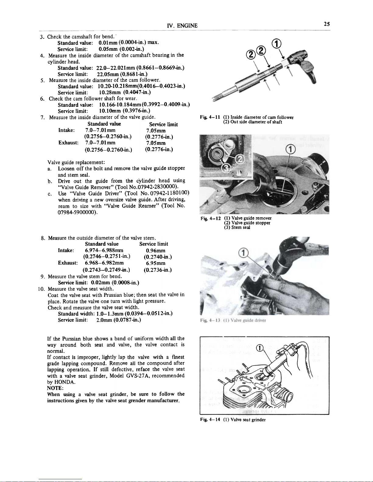
Fig. 4-11 (1) Inside diameter of cam follower
(2) Out side diameter of shaft
3. Check the camshaft for bend.'
Standard value: O.Olmm (O.OOO4-in.) max.
Service limit: O.O5mm (O.OO2-in.)
4. Measure the inside diameter of the camshaft bearing in the
cylinder head.
Standard value: 22.0-22.021mm (O.8661-0.8669-in.)
Service limit: 22.05mm (O.8681-in.)
S. Measure the inside diameter of the caro follower.
Standard value: lO.20-10.218mm(O.4016-0.4023-in.)
Service limit: lO.28mm (O.4047-in.)
6. Check the caro follower shaft for wear.
Standard value: lO.166-10.184mm(O.3992-0.4009-in.)
Service limit: lO.lOmm (O.3976-in.)
7. Measure the inside diameter of the valve guide.
Standard value Service limit
lntake: 7.0-7.01mm 7.05mm
(O.2756-0.2760-in.) (O.2776-in.)
Exhaust: 7.0-7.01mm 7.05mm
(O.2756-0.2760-in.) (O.2776-in.)
Valve guide replacement:
a. Loosen off the bolt and remove the valve guide stopper
and stem seal.
b. Drive out the guide from the cylinder head using
"Valve Guide Remover" (Tool No.07942-2830000).
c. Use "Valve Guide Driver" (Tool No. 07942.1180100)
when driving a new oversize valve guide. After driving,
ream to size with "Valve Guide Reamer" (Tool No.
07984-5900000) .
Fig. 4-12 (1) Valve guide remover
(2) Valve guide stopper
(3) Stem seal
8. Measure the outside diameter of the valve sterno
Standard value Service limit
lntake: 6.974-6.988mm O.96mm
(O.2746-0.2751-in.) (O.2740-in.)
Exhaust: 6.968-6.982mm 6.95mm
(O.2743-0.2749-in.) (O.2736-in.)
9. Measure the valve stem for bend.
Service limit: O.O2mm (O.OOO8-in.)
lO. Measure the valve seat width.
Coat the valve seat with Prussian blue; then seat the valve in
pIace. Rotate the valve one turo with light pressure.
Check and measure the valve seat width.
Standard width: 1.0-1.3mm (O.O394-0.0512-in.)
Service limit: 2.0mm (O.O787-in.)
If the Purssian blue shows a band of uniform width ali the
way around both seat and valve, the valve contact is
normal.
If contact is improper, lightly lap the valve with a finest
grade lapping compound. Remove ali the compound after
lapping operation. If stili defective, reface the valve seat
with a valve seat grinder, Model GVS-27 A, recommended
by HONDA.
NOTE:
When using a valve seat grinder, be sure to follow the
instructions given by the valve seat grender manufacturer.
Fig. 4-14 (1) Valve seat grinder

26
IV. ENGINE
Assembly
Valve and torsion bar valve spring
1. lnstall the outer torsion bar to the torsion bar valve spring.
Fig. 4-15 (1) Outer torsion bar
(2) Torsion bar bolder
2. lnstall the torsion bar assembly and outer arm to the
cylinder head.
1'.g. 4-16 (l) Torsion bar assembly
(2) Outer arm
3. lnstall the valve, valve spring retainer and valve cotters.
NOTE:
After assembly, check to make sure that the valve stem and
the fork of the outer arm is not binding. If they afe
binding, the valve stem may be bent.
4. Use a torque wrench and "Valve Ufter" (Tool No.
07973-2830001), torque the torsion bar to make su re that
it has been torqued to the proper value and lock the holder
with the dowel pino
Specified torque: 51.2-64.0 kg-cm (3.7-4.6Ibs-ft)
5. Tighten the holder with the bolt.
NOTE:
The torque wrench is used to test the strength of the valve
torsion bars. If the above force is required to line up the
dowel and end cap, alI is correct. If less force is required,
replace torsion bar valve springs.
Hg.4-IM (I)Valvelifter
(2) Torque wrench
(3) Dow~l pin
IV. ENGINE
27
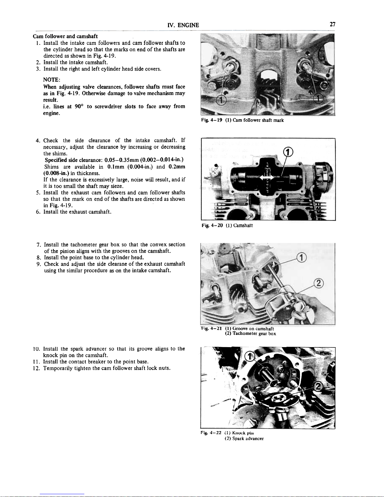
Caro follower and camshaft
l. lnstall the intake caro followers and caro follower shafts to
the cylinder head so that the marks on end of the shafts afe
directed as shown in Fig. 4-19.
2. Insta11 the intake camshaft.
3. Instal1 the right and left cylinder head side covers.
NOTE:
When adjusting valve clearances, follower shafts musi face
as in Fig. 4-19. Otherwise damage to valve mechanism may
result.
i.e. lines at 900 to screwdriver slots to face away from
engine.
Fig. 4-19 (1) Cam foIlower shaft mark
4. Check the side clearance of the intake camshaft. lf
necessary, adjust the clearance by increasing or decreasing
the shims.
Specified side clearance: O.O5-0.35mm (O.OO2-0.014-in.)
Shirns afe available in O.lmm (O.OO4-in.) and O.2mm
(O.OO8-in.) in thickness.
lf the clearance is excessively large, noise will result, and if
it is too small the shaft may sieze.
5. lnstall the exhaust caro followers and caro follower shafts
so that the mark on end of the shafts afe directed as shown
in Fig. 4-19.
6. lnstall the exhaust camsllaft.
l'"ig. 4-20 (1) Carnshaft
7. lnstall the tachometer gear box so that the convex section
of the pinion aligns with the grooves on the camshaft.
8. lnstall the point base to the cylinder head.
9. Check and adjust the side clearane of the exhaust camshaft
using the similar procedure as on the intake carnshaft.
!'tg. 4-21 (l) Groove on camshaft
(2) Tachometer gear box
l U. lnstall the spark advancer so that its groove aligns to the
knock pin on the camshaft.
Il. lnstall the contact breaker to the point base.
12. Temporarily tig/lten the caro follower shaft lock nuts.
,'.g. '+-"" \l} I\.nOCK pm
(2) Spark advancer
28
IV. ENGINE
~
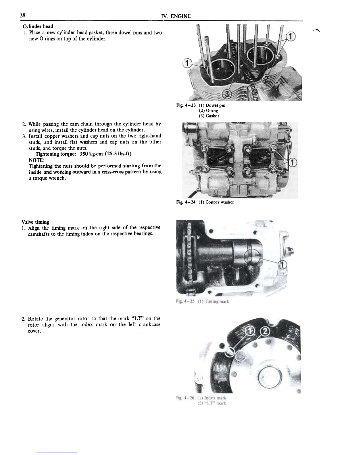
Cylinder head
l. PIace a new cyIinder head gasket, tl1ree doweI pins and two
new O-rings on top of the cyIinder.
Fig. 4-23 (1) Dowel pin
(2) O-ring
(3) Gasket
2. While passing the cam chain through the cylinder head by
using wires, install the cylinder head on the cylinder.
3. lnstall copper washers and cap nuts on the two right-hand
studs, and install flat washers and cap nuts on the other
studs, and torque the nuts.
Tightening torque: 350 kg-cm (25.3Ibs-ft)
NOTE:
Tightening the nuts should be performed starting from the
inside and working outward in a criss-cross pattem by using
a torque wrench.
Fig. 4-24 (1) Copper washer
Valve timing
l. Align the timing mark on the righi side of the respective
camshafts to the timing index on the respective bearings.
2. Rotate the generator rotor so that the mark "LT" on the
rotor aligns with the index mark on the left crankcase
cover.
 Loading...