

Page 1
5 YEAR LIMITED WARRANTY
WHAT IS COVERED
This product is guaranteed to be free of factory defective parts and workmanship for a period
of 5 years from date of purchase. Purchase receipt is required for all warranty claims.
WHAT IS NOT COVERED
This guarantee does not included repair service, adjustment and calibration due to misuse,
abuse or negligence, or LEDS. Unauthorized service or modification of the product or of any
furnished component will void this warranty in unauthorized service, or return shipping
charges. This warranty is not extended to other equipment and components that a customer
uses in conjunction with this product.
FCC INFORMATION
This device complies with Part 15 of the FCC Rules. Operation is subject to the following two
conditions: (1) This device may not cause harmful interference, and (2) This device must
accept any interference received, including interference that may cause undesired operation.
Warning: Changes or modification to this unit not expressly approved by the party responsible
for compliance could void the user’s authority to operate the equipment. NOTE: This
equipment has been tested and found to comply with the limited for Class B digital device,
pursuant to Part 15 of the FCC Rules. Their limits are designed to provide reasonable protection against harmful interference in a residential installation. This equipment generates, uses
and can radiate radio frequency energy and, if not installed and used in accordance with the
instructions, may cause harmful interference to radio communications. However, there is no
guarantee that interference will not occur in a particular installation. If the equipment does
cause harmful interference to radio or television reception, which can be determined by turning
the equipment off and on, the user is encouraged to try to correct the interference by one or
more of the following measures:
- Reorient or relocate the receiving antenna.
- Increase the separation between the equipment and the receiver.
- Connect the equipment into an outlet on a circuit different from that to which the receiver is
connected.
- Consult the dealer or an experienced radio/TV technician for help.
ISED Information
CAN ICES-005(B)/NMB-005(B)
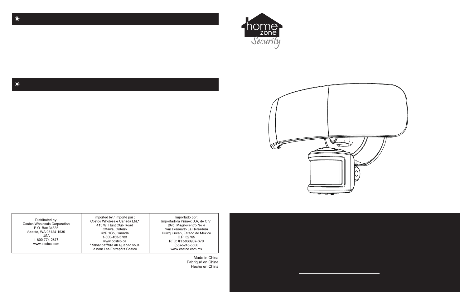
TRIPLE HEAD
TM
MC
MR
LED MOTION SENSOR
SECURITY LIGHT
ITM. / ART. 1193826
Model. AEC-5340
ES00697G
IMPORTANT! Retain this instruction manual for future reference: Please read these instructions carefully prior to installation. Failure to follow any of these instructions could void product
warranties. Test Rite assumes no responsiblity for claims arising out of improper or careless
installation or handling of it’s products.
Do not return to the store before calling ACS. For questions regarding this product or warranty,
please contact American Customer Service at 1-855-232-6427; serving in English, Spanish
and French, Monday through Friday, 8am to 8pm Eastern Time. Outside of business hours you
can reach us by e-mail at [email protected] and we will reply to you on the
next business day. Please enter the Costco item number # 1193826 in the subject line.
Page 2
IMPORTANT SAFETY INSTRUCTIONS PRE-INSTALLATION
- To reduce the risk of death, personal injury or property damage from fire, electric shock, falling parts, cuts/abrasions
and other hazards read all warnings and instructions included with and on the fixture box and all fixture labels.
- Before installing, servicing or performing routine maintenance upon this equipment, follow these general
precautions.
- If you are unsure about the installation or maintenance of this fixture, consult a qualified, licensed electrician.
o Do not mount the unit against flammable surfaces.
o The motion detector will not operate correctly if it is installed:
Near the outlet of a central heating boiler
Near an air conditioning unit
Pointing directly at moving vehicles
Within sight of reflection from moving water
Where other lamps could shine on the detector
- Fixtures can’t be used with a dimmer switch, motion or occupancy sensor and other electronic switching devices
unless otherwise designated. LED fixtures must be powered directly off a switch circuit.
- This fixture should not be used in areas with limited ventilation or high ambient temperatures.
- This fixture is intended to be connected to a properly installed and grounded UL listed junction box.
- These instructions do not claim to cover all details or variations in equipment or provide every possible contingency
to meet in connection with the installation, operation or maintenance. Should further information be needed, you may
contact American Customer Service at 1-855-232-6427.
!
WARNING: RISK OF ELECTRICAL SHOCK
Turn off electrical power at fuse or circuit breaker box before wiring fixture to the power supply.
Verify that the supply voltage is correct. Connect fixture to a 120 volt, 60 Hz power source.
Make sure all electrical and grounded connections are in accordance with the National Electrical Code and any
applicable local code requirements.
All wiring connections should be capped with UL listed wire connectors.
!
CAUTION: RISK OF PRODUCT DAMAGE
Never connect components under load.
Do not mount or support these fixtures in a manner that can cut the outer jacket or damage wire insulation.
Avoid covering LED fixtures with insulation, foam, or other material that will prevent convection or conduction cooling.
Never connect an LED product directly to dimmer packs, occupancy sensors, timing devices or other related control
device, unless individual product specifications deem otherwise.
Unless individual product deems otherwise: do not exceed fixtures maximum ambient temperatures.
LED products are Polarity Sensitive. Ensure proper polarity before installation.
Electrostatic Discharge (ESD) can cause damage to LED fixtures. Personal grounding equipment must be worn
during all installation or servicing of the unit.
Do not touch the individual electronic components, it may cause ESD, shorten lamp life or alter performance.
!
CAUTION: RISK OF INJURY
Wear gloves and safety glasses at all times when removing fixture from carton, installing, servicing or performing
maintenance.
Avoid direct eye exposure to the light source while it is on. LED LAMPS ARE EXTREMELY BRIGHT. UNDER NO
CIRCUMSTANCES SHOULD YOU STARE INTO AN LED BEAM, THIS MAY CAUSE IRREPARABLE DAMAGE
TO THE EYE.
Account for small parts and destroy packaging materials, as these may be hazardous to children.
!
WARNING: RISK OF BURN
Allow fixture to cool before handling. Do not touch enclosure of light source.
Do not exceed the maximum wattage marked on the label.
Keep combustible and other materials that can burn away from the luminaries, fixture and lamp/lens.
Before beginning assembly of the product, make sure all parts are present. Compare parts with
package contents list and hardware contents. If any part is missing or damaged, do not attempt
to assemble the product.
Estimated assembly time: 20 minutes.
Note: Fixture should be installed by persons with experience
in household wiring or by a qualified electrician. The
electrical system and the method of electrically connecting
this fixture to it must be in accordance with the National
Electrical Code and local building codes.
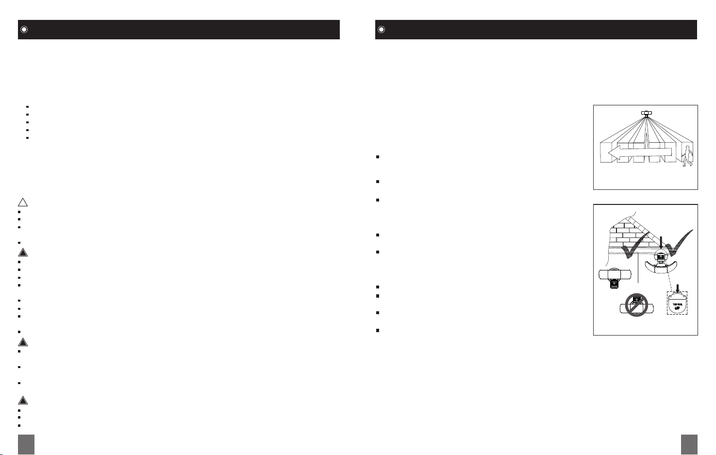
Install the motion sensor between 1.9 m / 6.2 ft and
3 m / 9.8 ft above the ground. Motion sensor is less
sensitive above 3 m / 9.8 ft.
Mount motion sensor so motion moves across detection
Sensor detects motion that moves
across the detection zone
zone.
Mount sensor away from heat producing sources to
prevent false triggering. Also be very careful not to
include objects such as windows, white walls and water
in the detection zone.
Mount fixture away from moving objects such as trees
and street traffic.
Suitable for wall mounting or eave mounting.
MOUNTING LOCATIONS
Wall Mount
Eave Mount
Determine the mounting location – a Wall or Eave.
Make sure “This side UP” of sensor face up after
installation.
THIS SIDE
Position the lamp head in the general direction of the
desired light coverage.
If needed, adjust the motion sensor up and down so the
controls face the ground after installation.
Note: Do not mount this light fixture on the ground.
Important notes:
1. Environmental temperature affects the sensor range. It is recommended not to mount
the fixture near a heat source like an air conditioner, vent, or furnace exhaust, or in a
direction facing a light reflecting object.
2. The sensor will be more sensitive to motion across its detection path than motion coming
directly towards it.
3. For best performance, gently clean the lens with a soft cloth every two months to assure
maximum sensitivity.
02 03
Page 3
PRE-INSTALLATION (Continued) INSTALLATION
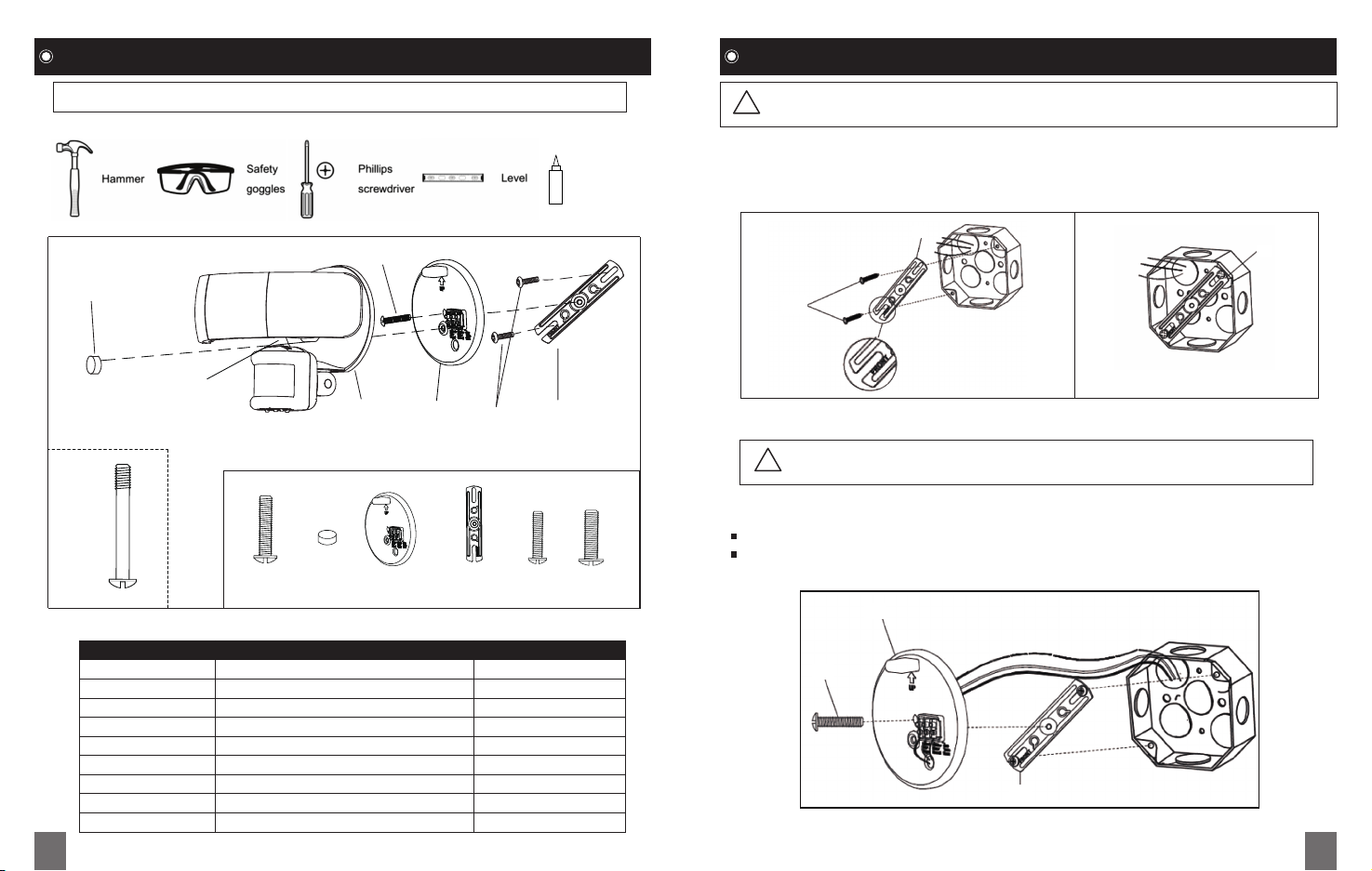
Tools Required for Installation (not included)
Silicone
Sealant
WARNING: Risk of electric shock. Disconnect power at fuse or circuit breaker
!
before installing or servicing.
Step 1. Installing the Mounting Bracket
- Line up the holes on the Mounting Bracket ( E ) with the holes on your junction box. Using
the two Mounting Screws ( F or G ) fit the junction box.
E
E
C
B
F or G
H
A
H
Part Description Quantity
A Light Fixture 1
B Small mounting bolt 1
C Decorative Cover 1
D Mounting Plate 1
E Mounting Bracket 1
F #6-32 X 3/4” Junction Box Screw 2
G #8-32 X 3/4” Junction Box Screw 2
H Large mounting bolt (pre-installed) 1
User Manual 1
04 05
B C D E F G
FIXTURE PACKING LIST
D
F or G
E
Step 2. Installing the mounting plate
- Take the junction box wires through the hole in the mounting plate (D).
- Place the mounting plate (D) against the junction box.
When mounting to a wall, the “UP” arrow must point upward.
When mounting to an eave, the “UP” arrow must point toward the building.
CAUTION: Do not cut any wires with factory installed wire connectors or
!
remove the wire connectors
D
B
E
Page 4
INSTALLATION (Continued) INSTALLATION (Continued)
- Insert the small mounting bolt (B) through the mounting plate (D) hole and mounting bracket
(E) hole. Tighten the bolt (B) securely.
- Firmly pull on the mounting plate (D) to verify it is securely attached to the mounting bracket
(E).
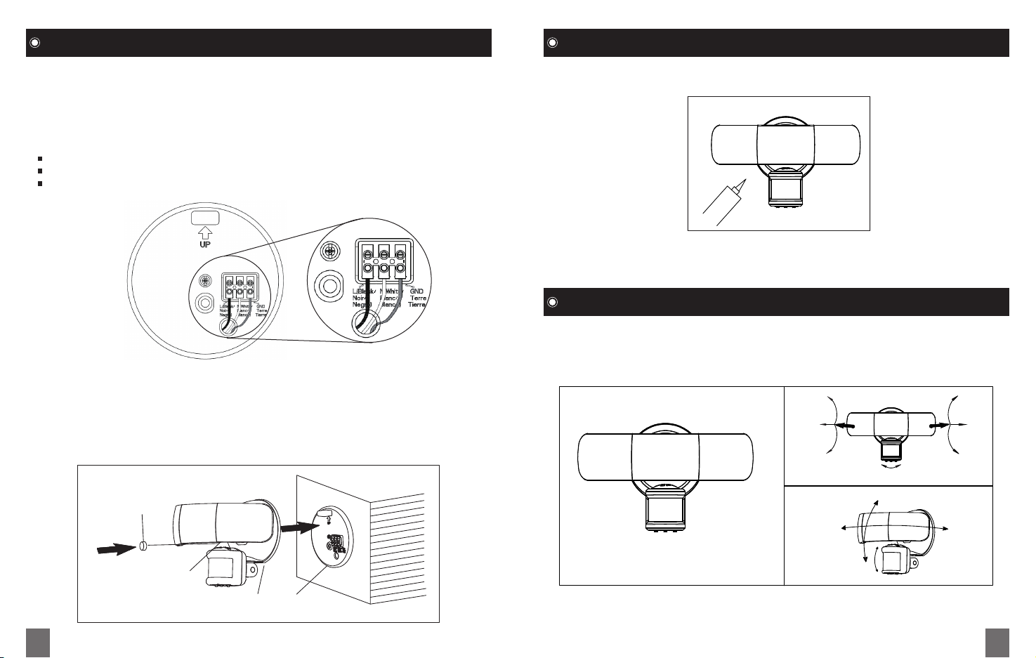
Step 3. Marking the electrical connections
- Insert the junction box wires into the side of the terminal block.
Insert the white wire from the junction box into the terminal marked “N (White)”.
Insert the black wire from the junction box into the terminal marked “ L (Black)”.
Insert the green ground wire from the junction box into the terminal marked “GND”.
Step 4. Mounting the light fixture
- Align the bottom edge of the light fixture (A) with the bottom edge of the mounting plate (D).
Tilt the light fixture (A) toward the mounting plate (D), marking sure the light fixture (A) is
centered on the mounting plate (D).
- Tighten the large mounting bolt (H) securely through the center of the mounting plate (D). Do
not overtighten.
- Push the rubber plug (C) firmly into the large mounting bolt hole on the light fixture (A).
Step 5. Caulking Around the Light Fixture
- Caulk around the canopy and mounting surface with silicone sealant (not included).
Note: For installing this light fixture on a covered wall or eave without junction box,
please call the customer service number listed on the front and back cover of this
manual.
OPERATION
1. Adjusting the Lamp heads and Sensor
-
Lamp heads can be adjusted easily. You may adjust the lamp head left and right or up and
down to get the desired lamp direction.
- Sensor can be adjusted easily. You may adjust the sensor left and right or up and down to
get the desired lamp direction.
45º
25º
90º
40º 40º
45º
25º
90º
C
45º
25º
25º
H
A D
06 07
Note: LED LAMPS ARE NON-REPLACEABLE. Do not attempt to access / maintain the
LEDs; they are non-replaceable and any contact may damage the LEDs and will void the
warranty.
80º
25º
Page 5
OPERATION (Continued) OPERATION (Continued)
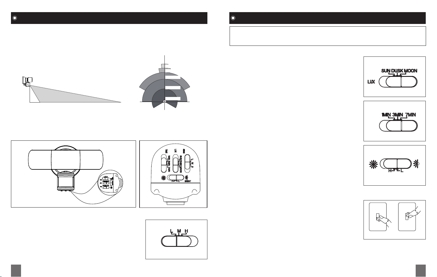
2. Adjusting the detector
After installing your motion activated light, you are ready to set /aim the motion detector.
Detection Range: around 21.3 m / 70 ft x 240 degrees ( Max )
The higher the “ SENS” setting (sensitivity), the greater the possibility of false
triggering. To reduce false triggering, suggest to slide the “SENS” switch toward
the “L” (low) setting if you don’t need long detection distance while using this light.
21.3 m / 70 ft detection range, it upon on ambient temperature 25 Celsius degree.
- Adjust the sensor head horizontal for long coverage.
10º
21.3 m / 70 ft
18 m / 59 ft
20º
12 m / 39.3 ft
8 m / 26.2 ft
2.5 m
/ 8.2 ft
1 m / 3.2 ft 21.3 m / 70 ft
140º
180º
5 m / 16.4 ft
1 m / 3.2 ft
240º
Note: When you first install your security light, you must aim the detector head to cover
the desired area.
Rotate the motion sensor so the controls face toward the ground.
- LUX Setting
This setting is used to control the ambient light level for the
motion security light to turn on after motion detection.
Slide the “LUX” switch toward the “SUN” position, the light
to turn on in the daylight or in sunset or in the darkness.
Slide the “LUX” switch toward the “DUSK” position, the light
to turn on in the sunset or in the darkness..
Slide the “LUX” switch toward the “MOON” position, the light
to turn on in the darkness.
- TIME Setting
This setting is used to control the time span of how long the
light remains on when motion is detected.
Set the “TIME” switch to the 1, 3, 7 minutes position. The
security light will stay on as long as motion is detected and
will go off after the time span you set after no motion is
TIME
detected.
- BRIGHT Setting
This setting is get the brightness of light.
Slide the “BRIGHT” switch toward the “H” position, the
light will get high lumen output.
Slide the “BRIGHT” switch toward the “L” position, the
BRIGHT
light will get low lumen output.
3. Manual Override Function
- When power is on, the PIR sensor enters a “warm-up” period for
about 40 seconds, then automatically switches into AUTO MODE.
- During AUTO MODE, by switching the main switch OFF for about
1 second then ON, the PIR sensor will automatically change into
- SENS Setting
Adjust the SENS setting to adjust range of Passive Infrared
Motion Sensor
- Slide the “ SENS” switch toward the “L” (low) position for
short detection range.
- Slide the “ SENS” switch toward the “M” (middle) position
for middle detection range.
- Slide the “ SENS” switch toward the “L” (high) position for
long detection range.
SENS
MANUAL MODE from AUTO MODE. In MANUAL MODE, the lights
will remain ON, and will NOT be controlled by time duration or
ambient light (LUX) levels.
The MANUAL MODE will change to
AUTO MODE in 6 hours automatically.
- During MANUAL MODE, by switching the main switch OFF over
30 seconds then back ON again, the PIR sensor will reset to the
Turn the switch
OFF for 1 second
“warm-up” period.
4. Blue LED sensor indicator
The Blue LED Light will flash to show that the PIR sensor is functioning properly.
Turn the switch
back ON
08 09
Page 6
SPECIFICATIONS
1. Detection Method: Passive Infrared Sensor (PIR). PIR measures infrared light radiating
from objects in its field of view. Apparent motion is detected when infrared levels change.
2. Sensor Range: Up to 21.3 m / 70 ft x 240 degree spread (Varies with surrounding temperature).
3. Time Adjustment: 1, 3, 7 minutes.
4. Power Source: 120VAC/60Hz, 37W.
5. Load Rating: No extra lights should be added to this unit.
ADVANTAGES OF LED’S
1. Energy saving – much lower power consumption and $$$ savings.
2. Longer lifetime – Solid State lighting has no filament to break.
3. Light does not radiate heat.
CARE AND CLEANING
- To prolong the original appearance, clean with clear water and a soft, damp cloth only.
- Do not use paints, solvents, or other chemicals on this light fixture. They could cause a
premature deterioration of the finish. This is not a defect in the finish and will not be covered
by the warranty.
- Do not spray with a hose or power washer.
REPLACEMENT PARTS LIST
For replacement parts, call our customer service department at 1-855-232-6427; serving in
English, Spanish and French, Monday through Friday, 8am to 8pm Eastern Time. Outside of
business hours you can reach us by e-mail at [email protected] and we
will reply to you on the next business day. Please enter the Costco item number # 1193826 in
the subject line.
TROUBLESHOOTING
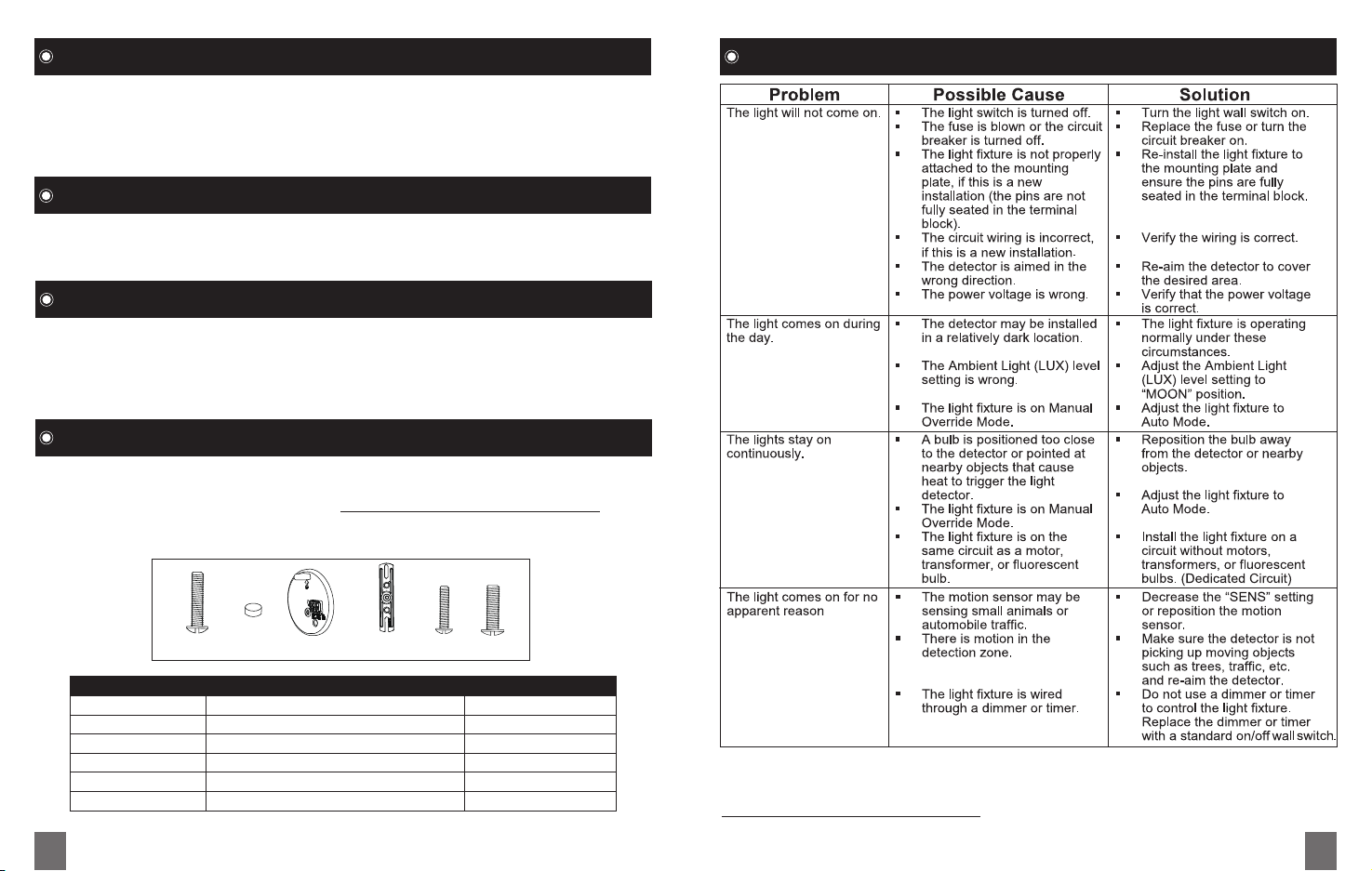
B C D E F G
Part Description Quantity
B Small mounting bolt 1
C Decorative Cover 1
D Mounting plate 1
E Mounting Bracket 1
F #6-32 X 3/4” Junction Box Screw 2
G #8-32 X 3/4” Junction Box Screw 2
10 11
For further questions or assistance, please contact American Customer Service at
1-855-232-6427; serving in English, Spanish and French, Monday through Friday, 8am to
8pm Eastern Time. Outside of business hours you can reach us by e-mail at
[email protected] and we will reply to you on the next business day.
Please enter the Costco item number # 1193826 in the subject line.
 Loading...