

Page 1
INSTRUCTIONS
&
No. LM - 1 6002 - 87
36" FRONT BLADE
AND LIFT LEVER
For: RM-5. RM-5E, Sl RM-yE
ACTOR
.
.....
........................................................ " Ni%iiii"îi;^.........................................................................................
PART No. 24716-4
SUPERSEDES 24716 & 24730
PRINTED IN U.S.A.
Page 2
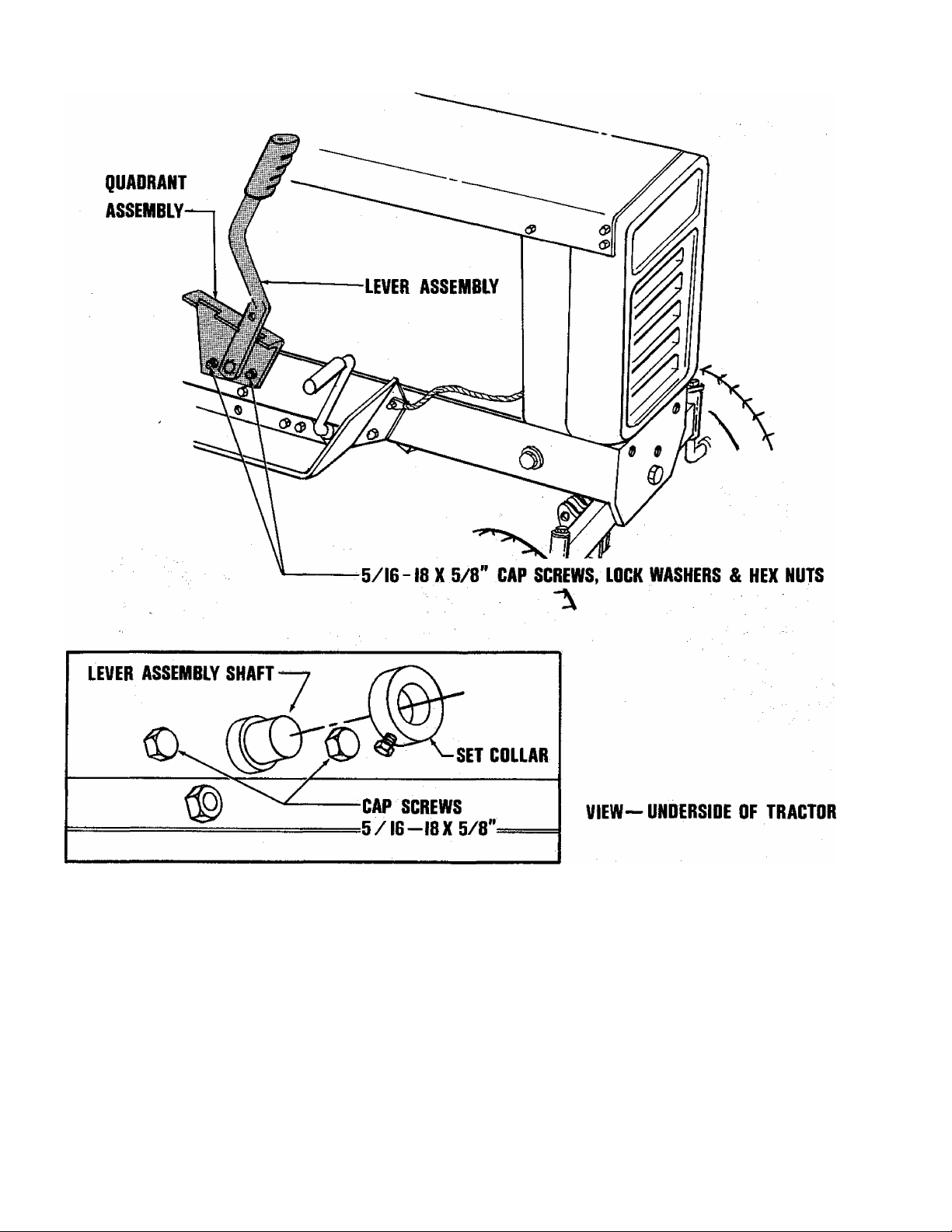
LIFT LEVER MOUNTING INSTRUCTIONS
The lift lever kit mounts to the tractor frame on the right hand side of the tractor
as shown in the illustration. It should be installed as follows:
1. Secure the quadrant assembly to the tractor frame using two 5/16-18 x 5/8
capscrews, lockwasher and hex nuts. Bolt heads must be inside tractor frame.
2. Slide the shaft on the lever assembly through the hole in the quadrant assembly.
3. Install the set collar on the end of the shaft and secure with a setscrew.
NOTE: Install set collar just tight enough so that lever assembly is not
loose, yet moves easily.
Page 3

36” FRONT BLADE ASSEMBLY INSTRUCTIONS
ASSEMBLY
1. Secure the front blade support to the front of the tractor
using three 3/8" capscrews, lockwashers and hex nuts.
2. Attach the push bar to the blade using a king pin in the
forward hole and a pivot pin in the rear hole.
3. Secure the push bar to the front blade support using the
pivot rod. Secure the rod with a quick pin at each end.
4. Place the tractor lift lever in the forward position. Using
a yoke pin and quick pin, mount the yoke end of the lift
rod on the lift arm of the push bar assembly. Insert the
hooked end of the rod through the hole in the lift and
secure with a quick pin.
ADJUSTMENTS
The front blade may be angled for plowing to the left or
right. Remove the pivot pin, adjust the blade to the desired
angle and replace the pivot pin.
Alternate holes are provided in the blade to adjust the shoe
assemblies for various types of ground to be plowed. The
blade should be raised when plowing gravel drives or walks.
Lower the blade when plowing asphalt or concrete drives or
walks.
The wear plate on the blade is reversible. Should it be
come worn, it may be removed, reversed and reinstalled.
Recommended Accessories
TIRE CHAINS
RM-5, RM-5E
RM-7
WHEEL WEIGHTS
Note: Loose mounting of chains will make them self-cleaning.
LM-09901-24
LM-16002-39
LM-09904-49
Page 4

36” FRONT BLADE
LIFT LEVER
No.
1
2
3
4
5
6
7
8 PIN-quick
9 BAR ASSEMBLY-push
10 PIN-quick
11
12
13
14 ROD-Uft
15
Description
BLADE ASSEMBLY- 36"
BOLT-carriage-3/8-16 x 1
BOLT-carriage-3/8-16 x 3/4
PLATE-wear
WASHER-iock, 3/8
NUT-hex, 3/8-16
SHOE ASSEMBLY
ROD-pivot
SUPPORT-front blade
SCREW-cap, 3/8-16 x 2-3/4
NUT-hex jam, 1/2-20
-Part No.
LM-16035-99
LM-09232-32
LM-09221-10
LM-16036-06
LM-09169-65
LM-09169-50
LM-16035-73
LM-01067-88
LM-16035-70
LM-81610-45
LM-16036-03
LM-16073-14
' LM-09199-59
LM-16073-13
LM-09192-62
Qty.
1
4
7
1
14
14
2
1
1
4
1
1
3
1
1
Ko.
16 YOKE-rod endadj., 1/2-20 LM-01576-31 1
17 PIN-yoke, 1/2 LM-01543-05 1
18 PIN-pivot LM-16036-01 1
19 PIN-king LM-16036-02 1
20 GRIP-handle LM-16104-69 1
21 QUADRANT-lift LM-16073-08 1
22 SCREW-set, 5/16-18 x 5/16 LM-09117-12 1
23 GOLLAR-set LM-80210-10 1
24 SCREW-cap, 5/16-18 X 5/8 LM-09193-18 2
25 WASHER-lock, 5/16 LM-09173-56 2
26 NUT-hex, 5/16 LM-09173-72 2
27 LEVER-Uft LM-16073-10 1
Description
Accessory
PAINT-blue, 12 oz. spray can 24764
Part No.
tjty.
ALWAYS FURNISH MODEL AND SER
HOMELITE*
A taxtronl DIVISION, PORI CHESTER, H.Y. 10573
ro
CM
 Loading...