

Page 1

HOME LITE*
8H.P. TILLER
MFG. NO. 1600405 8 H.P: TILLER
TINE EXTENSION KIT MFG. 1^. 1600406
FURROW OPENER MFG. NO. 1600373
OPERATOR'S
RIHRURl
FORM - 1651767
PRINTED IN U.S.A.
749
Page 2

TABLE OF CONTENTS
Page
WARRANTY ........................................................................................................................ Inside Cover
SAFETY PRECAUTIONS ................................................................................................................ 1
ACCESSORIES ............................................................................................................................... 2
ASSEMBLING .................................................................................................................................. 2
OPERATION .................................................................................................................................... 4
ADJUSTMENTS ...............................................................................................................................5
MAINTENANCE ............................................................................................................................... 6
OFF-SEASON STORAGE ................................................................................................................8
TROUBLESHOOTING ..................................................................................................................... 8
SPECIFICATIONS ........................................................................................................................... 9
PARTS LISTINGS
PULLEY AND CONTROL GROUP
FRAME AND WHEELS ..............................................................................................................13
TINE EXTENSION KIT ...............................................................................................................14
FURROW OPENER .................................................................................................................. 14
DRIVE AND TINE GROUP ........................................................................................................15
DECALS .....................................................................................................................................17
...........................................................................................
11
CONGRATULATIONS!
This great new product is engineered with imagination and built with integrity to assure you maximum service and
performance for years to come. To completely understand the operation of your equipment and to take full
advantage of its many fine built-in features, study this instruction manual thoroughly before operating the machine.
The little time you spend reading now will repay you many times over in the time you save and the satisfaction you
gain in using your equipment properly and safely.
SAFETY PRECAUTIONS
i
Know the controls and how to stop quickly - READ THE
OWNER'S MANUAL.
Do not allow children to operate the Roticul. Do not allow
adults to operate it without proper instructions.
Clear the work area of objects which might be picked up and
thrown.
Keep all nuts, bolts and screws tight to be sure equipment is excessive grease,
in safe working condition.
Do not operate equipment when barefoot or wearing open
sandals. Always wear substantial footwear.
Handle gasoline with care - it is highly flammable.
A. Use approved gasoline container.
B. Never remove cap or add gasoline to a running or
hot engine or fill the fuel tank indoors. Wipe up
spilled gasoline.
C. Open doors if the engine is run in a garage. Exhaust
fumes are dangerous. Do not run engine indoors.
Never store equipment with gasoline in the tank inside a
building where fumes may reach an open flame or spark.
Allow the engine to cool before storing in any enclosure.
To reduce fire hazard keep the engine free of grass, leaves or
Release the clutch lever and stop the engine before cleaning
the tines, removing obstacles, making adjustments, or when
leaving the operating position.
Never allow children or pets to cross your path, or cause dis
tractions in the area while operating.
Use caution to avoid slipping or falling, expecially when op
erating in reverse.
\
1
Page 3
ACCESSORIES
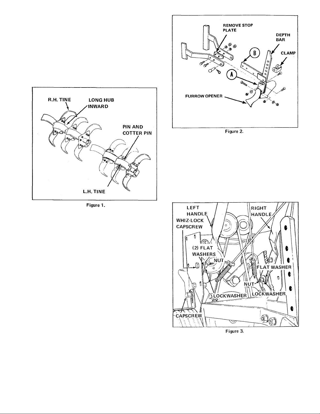
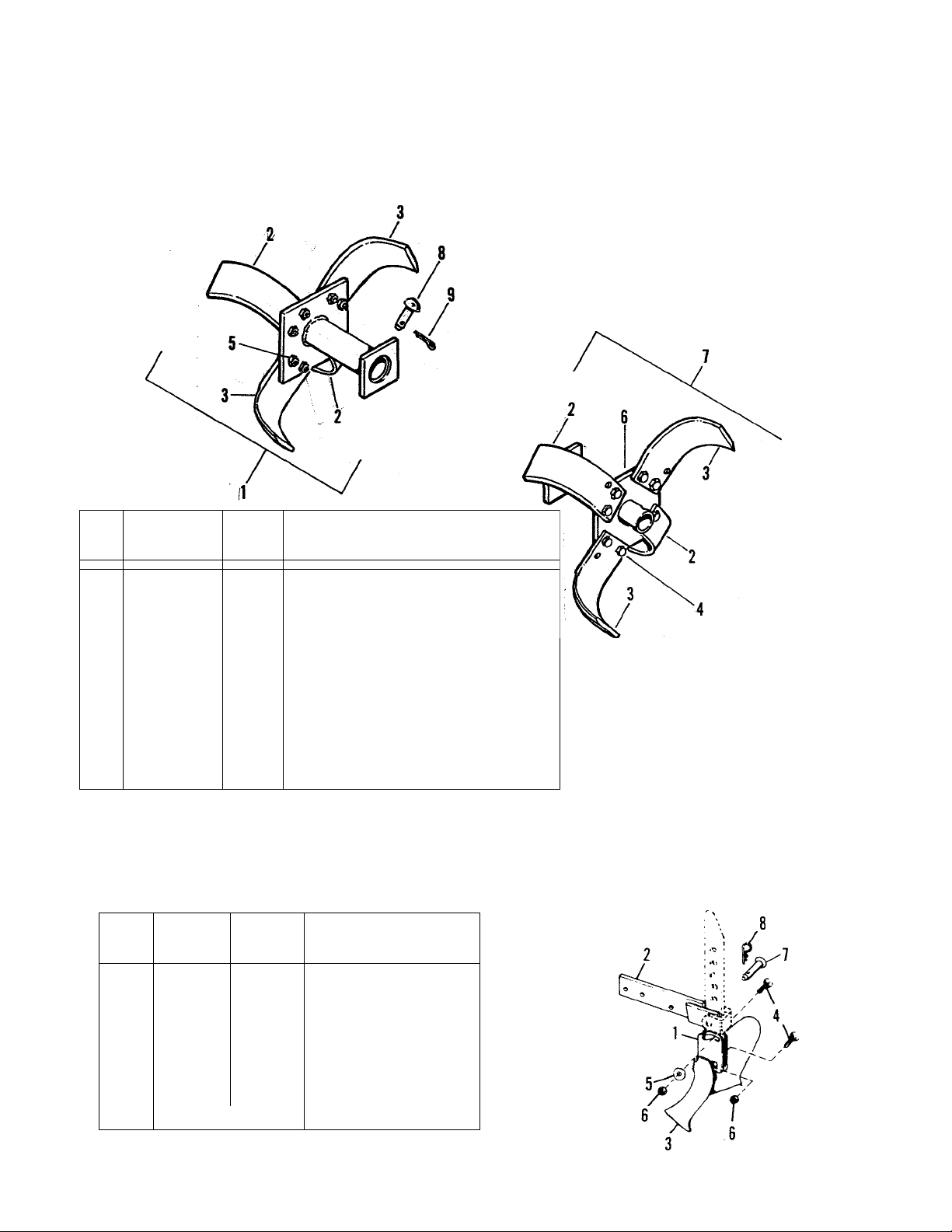
TINE EXTENSION SET (Mfg. No. 1600406)
See Figure 1. The extension set consists of a left and right
tine assemblies with mounting pins and cotter pins. Mount
long hub of extension over outside end of standard tine
assembly and secure assemblies together with pin and cotter
pin. Be sure sharpened edges of tines on top face forward.
The extension set increases effective tilling width to 35
inches.
ASSEMBLING
1. Remove all components of tiller from box and place them
in a clean, level area. Inspect each part for damage.
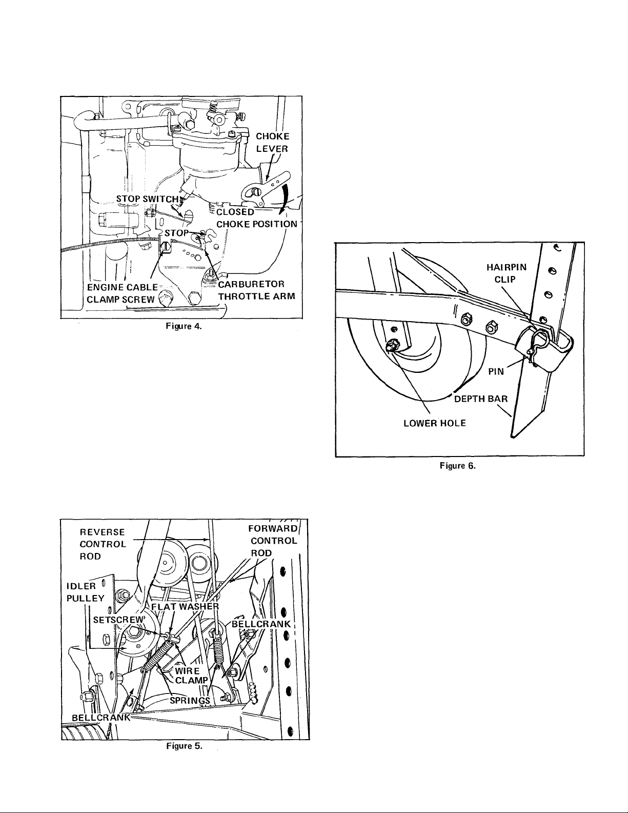
FURROW OPENER, 8-INCH (Mfg. No. 1600373)
See Figure 2. The furrow opener is intended for digging
furrows for crops which must be planted in rows. To install,
proceed as follows:
1. Remove the depth bar, turn it upside down and bolt it
to the tool holder (A) with the carriage bolts, washers and
nuts provided.
2. Remove the stop plate from between the frame supports
and install the extension support (B) with the old hardware.
3. Position the depth bar in the extension support and re
install the depth bar clamp using the pin and spring clip
provided. Bolt the furrow opener to the tool holder as
shown.
2. Remove belt cover.
3. See Figure 3. Assemble left and right handles to frame as
shown. Note locations of flat washers.
SPECIAL WORM GEAR OIL
CAUTION
Damage to the worm gear drive which results from
use of any lubricant other than that specified, will
invalidate the warranty. (See back cover for special
Worm Gear Oil Part Number).
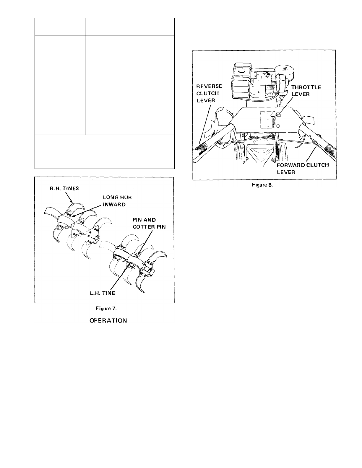
4. Connect throttle cable as follows:
a. See Figure 8. Move throttle control handle to FAST
position. Be sure throttle cable wire is securely attached
to throttle arm under control panel. From the throttle
Page 4
arm, the throttle cable must be secured to the right
handle with a clip. The cable must then pass outside the
right side of the cover and through a engine cable clamp.
Loosen engine cable clamp screw as required. See Figure
4.
c. See Figure 5. Adjust spring tension by loosening clamp
setscrews and moving clamps on control rods. Idler
pulleys should be 1/4-inch from frame when clutch dis
engaged (handle released). Belt stops should be 1/8-inch
from belts when clutch engaged (handle compressed. See
Adjustments section of this manual for clutch adjustment
procedure.
d. Secure cover to frame with six self-tapping screws.
6. Install wheel assemblies as follows:
a. Tilt unit forward on engine.
b. See Figure 6. Secure each wheel assembly (bushing
inward) to frame through lower holes in frame support
with a 3-1/2-inch long shoulder bolt, lockwasher, and
hex nut. Tighten hex nut.
b. See Figure 4. Insert loose wire end of throttle cable
in carburetor throttle arm. Lever should be in forward
position against stop in slot. Tighten engine cable clamp
screw.
c. See Figure 8. Move throttle control handle to STOP
position. Be sure stop switch opens. See Figure 4.
5. Install forward and reverse control rods as follows:
a. See Figure 5. Attach reverse and forward control rod
springs to bellcranks.
b. See Figure 5. Slide reverse and forward control rods
through wire clamps inside springs. Loosely secure rods
in clamps with setscrews and flat washers. Hook loose
end of springs on setscrews between flat washers and
clamos.
7. See Figure 6. Secure depth bar and clamp to rear of
frame with pin and hairpin clip. Digging tip of bar should
be installed as shown.
NOTE: The depth bar setting determines the depth of
tilling. To till 4 to 6 inches deep, install bar mounting pin
in second or third hole from the top. The deeper depth bar
is set into soil, the deeper tines will dig.
8. Loosen each wheel scraper nut and adjust scraper to
clear wheel by 1/8-inch. Tighten scraper nut.
9. Depending upon what tilling width desired, install right
and left tine blade assemblies as follows. Use a pin and
hairpin clip for installation. See Figure 7 for right inner,
outer and extension tine installation.
Page 5
TILLING WIDTH
(INCHES)
8-3/4
TINES USED
^switched left and right inner
CAUTION
Never grip both forward and reverse clutch levers at
the same time.
12-7/8
19-3/8
** 23-1/2
35
*Switched denotes movina normal left or riaht blade assembly to opposite side. Be sure sharpened edges face
forward.
**Standard tine arrangement.
left and right inner
left and right inner
* switched left and right outer
left and right inner
left and right outer
left and right inner
left and right outer
left and right extension
2. Engine
a. MANUALS. Read the engine owner's manual and this
operator's manual thoroughly.
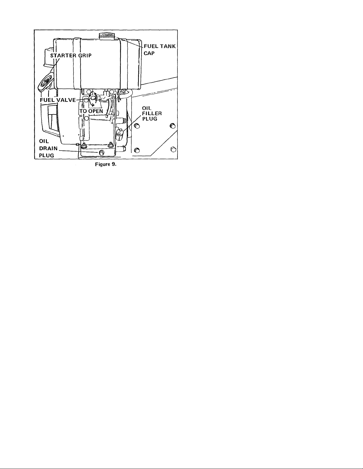
b. FUEL. See Figure 9. Have available sufficient quan
tities of clean, fresh (leaded or non-leaded), "regular"
automotive gEisoline. Remove fuel tank cap and fill
tank completely. Fuel capacity is 4 quarts.:
PREPARING
1. Controls
See Figure 8. Familiarize yourself with the following con
trols;
a. THROTTLE LEVER. Used to adjust ground speed or
to stop engine. See Figure 8 for throttle lever position
ing.
b. FORWARD AND REVERSE CLUTCH LEVERS.
Used to control forward or reverse action of the tiller.
Squeeze desired lever to engage and release to stop.
DO NOT MIX OIL WITH GASOLINE.
WARNING
Gasoline is highly inflammable. Avoid overfilling and
wipe up any spilled fuel. Allow no open flame, smok
ing or matches near the area when refueling.
Replace filler cap securely. Store gasoline only in small
quantities, prolonged storage produces gum and harmful
deposits. If it is necessary to store gasoline for long periods,
add a gasoline stabilizer. See Off-Season Storage section of
this manual.
c. OIL. See Figure 9. Have available sufficient quantitiesof engine crankcase oil, SAE 30 grade MS. Remove
dirt around engine filler plug. Remove engine filler plug
by turning counter-clockwise. Fill with oil until level
with top of neck. Crankcase capacity is 2-3/4 pints.
Reinstall filler plug securely. Check oil everytime fuel
is added.
Page 6
3. Depth Bar
See Adjustments section of this manual.
4. Wheels and Scraper.
f. If engine still fails to start, check fuel supply and
spark plug connections. Be sure engine stop switch is
closed (See Figure 4).
2. Operating
a. When operating the tiller for the first time, proceed
slowly and carefully to get the feel of the unit. Experi
ence will determine pressure and depth bar setting for
the operator.
b. Do not till when the soil is very wet. This causes
lumps which are difficult to work up. If the soil is ex
tremely hard and dry, it may be desireable to cross till an
area at shallow depth at first, then till in the direction
of planting rows on the second pass at the final depth.
Use reverse for working in tight areas and to dislodge
any rocks which may be caught between the tines and
worm gear housing.
c. Do not attempt to hold tiller back to cause the tines
to dig. Rather, adjust the depth bar so it will hold the
tiller back for you. When the tines have dug deep enough
in an area, raise up slightly on handles and the tiller will
move ahead. To stop the forward motion of the tiller,
put slight down pressure on the handles and the depth
bar will hold the tiller in place.
See Figure 6. Be sure wheels are mounted in the LOWER
holes of the frame support. If required, adjust wheel
scraper 1/8-inch above tire.
5. Tines
Be sure tines are installed securely with pin and cotter pin
Sharpened edges at the top must face forward. See As
sembly section of this manual for tine installation.
OPERATING
1. Starting
a. See Figure 8. Move throttle lever halfway between
SLOW and FAST position.
b. See Figure 4. Move choke lever to full CHOKE po
sition. If engine warm, use half choke. Choke arm should
be at right angles to exhaust tubing when in CLOSED
CHOKE position and parallel to tubing when in OPEN
CHOKE position,
c. See Figure 9. Be sure fuel valve is open.
d. To start engine, grasp starter grip (See Figure 9)
firmly in right hand and pull sharply straight out. Always
return grip by hand. Do not release the grip with rope
extended. Repeat if necessary with choke open slightly
(See Figure 4.) When engine starts, open choke grad
ually.
e. If engine fails to start after four or five pulls, it may
be flooded. Return choke to OPEN position and pull
out grip several times to clear excess fuel.
d. A furrow opener shovel is available for use in digging
furrows for crops which are planted in rows, such as po
tatoes. See Accessories section of this manual.
3. Stopping
a. Move the throttle lever (See Figure 8) to the STOP
position. The stop switch (See Figure 4) should open,
stopping the engine.
b. If the tiller has been operating under full load, allow
engine to idle for a minute to reduce engine temperature.
Stopping a hot engine suddenly may damage engine parts.
ADJUSTMENTS
BELT STOPS
All belt stops should be 1/8-inch from belts when clutch
engaged (handle compressed). To adjust, remove belt cover,
loosen stop mounting bolt, squeeze one clutch lever and
then the other, adjusting belt stop (sLas indicated in Figure
10. Tighten belt stop mounting bolt and replace cover.
NOTE: If tines will not stop turning after clutch lever is
released, belt stops may be too far from belts and not
braking belt as required when clutch handle released.
Page 7
DEPTH BAR
See Figure 6. The depth bar setting determines the depth
of tilling. To till 4 to 6 inches deep, install the bar mount
ing pind'n the second or third hole from the TOP. Pull out
the hairpin clip to change pin location. Be sure to install
the bar with the digging tip as shown. THE DEEPER THE
DEPTH BAR IS SET INTO THE SOIL, THE DEEPER
THE TINES WILL DIG.
CARBURETOR
Minor carburetor adjustments may be required to com
pensate for differences in fuel, temperature, altitude and
load. See your engine owner's manual for adjustment pro
cedures.
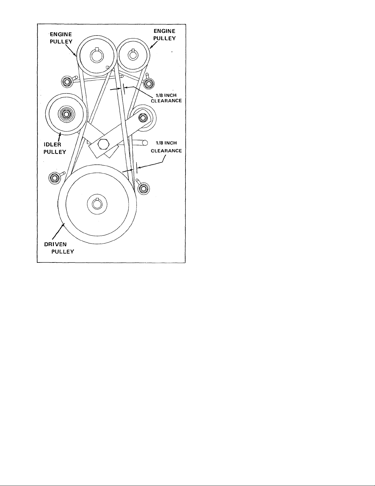
PULLEY ALIGNMENT
See Figure 10. Visually check alignment of engine, idler,
and driven pulleys. Pulleys must be aligned as closely as
possible or belts will be stretched and worn excessively.
Loosen engine and/or driven pulley setscrews and align
pulleys. Tighten setscrews securely.
Figure 10
CLUTCH
1. When clutch disengaged (handle released), idler pulleys
should be no closer than 1/4-inch from frame and all belt
stops must be firmly gripping the drive belts.
2. When clutch engaged (handle compressed), idler pulley
must press in on belt enough to remove belt from contact
with belt stops. Approximately 1/8-inch clearance between
belt stop and belt should be maintained. See Beit Stop
Adjustment.
3. See Figure 5. If clutch does not operate as described
above in steps 1 and 2, loosen wire clamp setscrew and ad
just wire clamp on forward or reverse control rod to obtain
required spring tension.
SCRAPERS
Loosen scraper mounting nut and adjust scraper in its slot
to 1/8-inch clearance above wheels. Tighten nut when
adjustment completed.
MAINTENANCE
Read the engine owner's manual thoroughly.
AFTER EACH USE
Grass, dirt, or chaff may clog engine cylinder head fins and
blower housing. Check for clogged condition and if nec
essary remove blower housing and clean.
CAUTION
Continued operation with a clogged cooling system
causes severe overheating and possible engine damage.
FIRST 5 HOURS OF OPERATION
See Figure 9. Change engine oil as follows:
a. Run engine for a few minutes to warm engine oil.
b. Remove oil drain plug and allow oil to completely
drain from engine.
c. Replace oil drain plug securely.
d. Remove dirt around engine oil filler plug.
e. Remove engine oil filler plug by turning counter
clockwise.
f. Fill with SAE 30 grade MS oil until level with top of
neck. Crankcase capacity is 2-3/4 pints.
g. Reinstall engine oil filler plug securely.
Page 8

EVERY 5 HOURS OF OPERATION
See Figure 11. Check and add worm drive housing gear oil
as follows:
a. Remove worm gear housing oil filler plug.
Worm Gear Oil Filler Plug
Figure 11.
CAUTION
There is a filter in a vent hole located at rear of worm
drive housing. Do not remove this filter for any reason.
a. Remove wing nut and cover.
b. Lift off foam element from base.
c. Push down foam element as shown and pull out air
cleaner cup.
d. Wash foam element in kerosene or liquid detergent
and water.
e. Wrap foam in cloth and squeeze dry.
f. Saturate foam in engine oil. Squeeze to remove excess
oil.
g. Put air cleaner cup inside element. Be sure sealing lip
is over top and bottom ends of cup.
h. Re-assemble air cleaner parts as shown. Screw wing
nut down securely.
b. Oil level should be level with plug hole when tines are
resting on ground.
c. If oil is required, tip tiller back until handles rest on
ground. Add a small amount of special worm gear oil
(See Back Cover for part number) through plug hole and
slowly lower tiller until tines rest on ground. Oil should
be level with plug hole, if not, repeat procedure. Do not
overfill.
CAUTION
Damage to the worm gear drive which results from use
of any other lubricant than that specified on back
cover, will automatically invalidate the warranty.
d. Tighten filler plug securely.
NOTE: The worm drive housing may become quite warm
while operating. This is completely normal and no harm to
gears will occur if the housing is kept filled as specified
with the special worm gear oil.
EVERY 25 HOURS OF OPERATION
1. Change engine oil. Refer to change procedure in FIRST
5 HOURS OF OPERATION.
2. See Figure 12. Clean air cleaner and re-oil element. The
capacity of the oil-foam air cleaner is adequate for a normal
full season's use without cleaning. However, under extremely
dusty conditions clean every few hours. Clean air cleaner
as follows;
Clean and reset spark plug gap at 0.030 of an inch. Plug
should be cleaned by scraping or wire brushing and washing
with a commercial solvent or gasoline. Grease the plug
threads before re-installing.
EVERY 200 HOURS OF OPERATION
See Figure 13. Clean fuel filter screen and bowl as follows:
WARNING
Do not remove fuel lines from fuel filter when engine
is hot.
1. Close fuel shutoff valve, loosen yoke, and remove bowl,
gasket, and screen.
2. Disgard gasket and replace it with new one.
3. Clean screen and bowl.
4. Using new gasket, assemble in reverse order of disassembly.
Be sure yoke is secure. Open fuel shutoff valve.
Page 9

LUBRICATION
1. See Figure 14. To reduce wear and assure free movement
of controls and tines, apply light motor oil occasionally at
points indicated. Be careful not to get oil on drive belts.
Use only small quantities of oil. Excess oil collects dirt and
causes extra wear.
Figure 13.
OFF-SEASON STORAGE
If tiller is to be stored over 30 days proceed as follows:
1. Glean fuel screen and bowl. See Maintenance section of
this manual.
2. Drain fuel tank and lines by placing suitable container
under fuel shutoff valve and opening valve. Store gasoline
in container using a gasoline stabilizer or additive. This ad
ditive can also be added to tanks instead of draining. This
additive prevents formation of gum and varnish for up to
one year.
3. Operate engine until gasoline in carburetor is completely
consumed.
4. While engine is still warm, drain oil from crankcase. See
Maintenance section of this manual. Refill with fresh oil.
5. Remove spark plug, pour one ounce (2 or 3 tablespoons)
of SAE-30 oil into cylinder and crank slowly to distribute
oil. Replace spark plug.
6. Clean dirt and chaff from cylinder head fins and blower
housing.
DO NOT OIL SELF-LUBRICATED WHEEL BEARINGS.
2. See Figure 15. Apply a light coat of grease or oil to in
side of tine: hubs and on tine shaft to prevent rust.
REPAIRS
----------------
TROUBLESHOOTING
IF ENGINE FAILS TO START
1. Fuel tank may be empty. See Figure 9.
2. Throttle lever is not set halfway between SLOW and
FAST position. See Figure 8.
3. Spark plug is not securely connected.
4. Choke lever is not in CLOSED CHOKE position or in
OPEN CHOKE position, if engine appears to be flooded.
See Figure 4. To clear a flooded engine, move choke lever
up to OPEN CHOKE position and pull starter rope several
times.
IF BELT SLIPPAGE OCCURS
1. Belts may be stretched or worn excessively. Replace belts.
2. Belts may be greasy or oils. If so, use cleaning fluid on a
rag to clean.
3. Pulleys may be misaligned. Refer to Pulley Alignment
in Adjustments section of this manual.
To prevent rust, sand off and paint any parts or areas which
become chipped or damaged. Tighten all bolts, nuts, and
fasteners securely.
4. Belt tension may be too loose. Refer to Clutch in
Adjustments section of this manual.
Page 10

SPECIFICATIONS
ENGINE
Make Briggs and Stratton
Model No. 190492
Type 0794-1
Cycles 4
Cylinders
Bore
Stroke
Displacement
Crankshaft Plane Horizontal
Starter
Choke
Governor Adjustable Mechanical
1 gnition Magneto
Lubrication Gear impeller system
Crankcase Capacity
Fuel Capacity
Air Cleaner
Muffler Lo-Tone, Side Discharge
1
3 1 nches
2-3/4 1 nches
19.44 Cu. In.
Manual, Easy spin
Manual
2-3/4 pints
4 Quarts
Sealed doing Housing, Reusable Oiled Foam Element
TR AKKMI QQIOM
Type Worm and Gear
Material Worm - Carburized Steel;Gear-Bronze
Bearings
Needle and Tapered Anti-Friction
Seals Double Lip - Dirt Excluding
Lubrication
Special Worm gear oil
Housing Cast Iron
Clutch
Hand Tensioning Belt Idler - Reverse and Forward
Page 11

SPECIFICATIONS (Cont'd)
TINES
Type Slashing, Self-sharpening
Material
Tilling Width 23-1/2 In. Standard, 35 In. With Tine Extensions
Tilling Depth
Attachments To shaft - Bolted
Depth Bar
Speed
nCDTU DAD
Attachment Pin and Spring Clip
Adjustment 0 to 8 Inches Tilling Depth
OUIM 1 KULo
Forged, High-Carbon Steel
0 to 8 Inches, Adjustable
Adjustable - 10 heights
116 RPM at Full Engine Speed
Location Forward Clutch - Right Handle,
Reverse Clutch - Left Handle
Throttle - Center
Rewind Starter and Choke - On Engine
UnAoolo
Frame
Tires
Heavy Duty, Electrically Welded with Cross Bracing
2.75 X 10 Heavy Duty, Semi-Pneumatic
Wheel Bearings Solid, Sintered Iron
OVERALL DllvlENSIONS
Length 53 Inches
Width
Height
Weight
26 Inches (Without Tine Extensions)
36 Inches (To top of handle)
164 Lbs. (net)
178 Lbs. (shipping)
SPECIFICATIONS ARE SUBJECT TO CHANGE WITHOUT NOTICE.
10
Page 12

PULLEY AND CONTROL GROUP
Ref.
No. Part No.
1
2 118439
3 176328
175964 1
4 172668 1
5 118458
6
7 911712 2
8 1609352
9
10
11
12
13 916965 2
14
15 1609352
16
17 174870 1 SPACER
18
19
20
21
22 121073
23
24
25
26 922249
27 917642
28
29 916950
30 922249
31 176393
32 176917
910224
154534
118335
921971 1 CAPSCREW, Hex, 3/8,
917642 2 WASHER, Flat, 5/16
916950
118414 1
921969
1609295
171336
923362
106707
106346
106347
916965 8
Qty. Description
PULLEY, Driven
1 Key
1
1 PULLEY
1 KEY, Woodruff,
1
2 NUT, full hex, 3/8-16
PULLEY
KEY
5/32 X 5/8
SETSCREW, 5/16-18
x5/16lg.
LEVER, Idler
1
1
1 LEVER, Idler pulley
1 CAPSCREW, Hex, 3/8-16
2 BELLCRANK
1
1 LOCKNUT, Full hex,
1
1
3
1
2 BOLT, Carriage, 3/8 -16
6
4
2
1 BELT, "V" (reverse)
1
PULLEY, Idler
SPACER
-16x 1-3/4
LOCKWASHER, 3/8
PULLEY, Idler
x 1-1/2" Ig.
BOLT, Pivot
5/16- 18
STOP, Belt
STOP, Belt
STOP, Belt
STOP, Belt
x 1-1/4 " Ig.
WASHER, Flat, 5/16
LOCKWASHER, 3/8
NUT, Full Hex,
3/8- 16
BOLT, Carriage, 3/8"-
16 X 1" Ig.
BELT, "V" (forward)
Ref.
No.
33
34
35
36
37 161092
38
39
40
41
42
43
44
45
46
47
48
49 918240
50
51
52
53
54
55
56
57
58
59
60
Part No.
929001
1609299
923360
1609378
928722
118495
1609354
1609344
922611
916950
928728
930579
106558
118237
118298
916964
916622
1609383
925003
1605216
164191
1609343
927428
1609300
918240
923358
Qty.
2
2
4
2
2
2
2
1
1
4
4
2
2
2
1
1
4
4
4
1
2
1
1
1
6
2
2
2
Description
LOCKNUT, Flange
ROD, Link
PIN, Cotter, 1/16 X 3/4
ROD, Control
CLAMP, Wire
SETSCREW, Sq. Hd., 10-24
x5/8
SPRING
HANDLE, Left
HANDLE, Right
WASHER, Flat, 13/32 x
1-1/4
NUT, Hex, 3/8-16
SCREW, Hex, whiz-lock
fig, 3/8-16 X 1
CAPSCREW, Hex, 3/8-
16 X 1-1/4
GRIP
CONTROL HOUSING ASSY.
COVER, Upper handle
CAPSCREW, Hex, 1/4-20
X 1-1/2
LOCKWASHER, 1/4
NUT, Hex, 1/4-20
CONTROL ASSY.,Throttle
SCREW, washer head, hex,
1/4-20 X 1/2
CLIP, Cable
PLUG,' Button
COVER. Belt
SCREW, Self-tapping,
1/4 -20 X 3/8
GRIP, Clutch
CAPSCREW, Hex, 1/4-20
X 1-1/2
LOCKNUT, Hex, 1/4-20
12
Page 13

FRAMES WHEELS
Ref.
No.
1
2
3
4
5
6
7
8
9
10
11
12
Part No. Qty.
177124
176196 2 BOLT, Shoulder
916966 2
916951
176364
922249 2
917642
916965
916950 2
118081 1
118371
105249 1 PIN
2
2
2
2
2
1
Description
WHEELS TIRE ASSY.
LOCKWASHER, 1/2
NUT, full hex, 1/2”-13
SCRAPER
BOLT, Carriage, 3/8"-
16 X 1"lg.
WASHER, Flat, 5/16"
LOCKWASHER, 3/8"
NUT, hex, 3/8"-16
BAR, Depth
CLAMP
Ref.
No.
13
14
15 118207 1 PLATE, Stop
16
17
18 916950
19 177123
20
21 917642
22
23 917372
Part No.
918196
1609342
919360 2
916965 2
917398
917356
Qty.
1 CLIP, Hairpin
1
2
1 ENGINE, 8 H.P.
4
4
4 -
4
13
Description
FRAME ASSEMBLY
CAPSCREW, Hex. 3/8"-
T6 x 1" Ig.
LOCKWASHER, 3/8"
NUT, full hex, 3/8"-16
CAPSCREW, Hex, 5/16-
18 X 1-3/4" Ig.
WASHER, Flat, 5/16"
LOCKWASHER, 5/16"
NUT, full hex,5/16"-18
Page 14
8 H.P. TILLER
MFG. NO. 1600406
TINE EXTENSION KIT
Ref.
No.
1
2
3
4
5
6
7
8
9
Part No.
1609387 1 TINE BLADE EXT. ASSY.,
172511 4 TINE, R.H.
172512 4 TINE, L.H.
925204
923428 16
1609386 2 TINE PLATE EXT. ASSY., Outer
1609388
118053 2
918451
Qty.
16
1
2 PIN, Cotter, 1/8X 3/4
Description
L.H. (Consists of Ref. No. 2 throygh 6)
CAPSCREW, Hex, 3/8" -16 x 1/2
LOCKNUT, Hex, 3/8-16
TINE BLADE EXT. ASSY., R.H.
Consists of Ref. no. ^ through 6
PIN
Ref.
No. Part No. Qty. Description
8 H.P. TILLER
MFG. NO. 1600373
FURROW OPENER
1
2
3
4
5
6
7
8
8271503 1
118287 1
103010 1 OPENER, Furrow, 8-Inch
922109 2
917378 1 WASHER, Flat, 3/8
916950
118053 1
918196
2 NUT, Hex, 3/8
L_J
_______
TOOL HOLDER ASSY.
SUPPORT ASSEMBLY
BOLT, 3/8-16 X 1-1/4
PIN
CLIP, Hairpin
14
Page 15

DRIVE AND TINE GROUP
Page 16

Ref.
No. Part No.
DRIVE & TINE GROUP
Qty.
Description
1
2
3
4 925204 32
5 923428
6
7 176467
8 1609387
9
10 1609388
11
12 118053 2
13 918451 2
14 175871 1 HOUSING, Worm Drive
15
16 118393
17
18 154393
19 118396
20
21
22 171762
23 176013
24
25
26 118399
27
28
29 154487
30 118020 2
31 118118
32
33 176011
34 930246
35
36 175872
37 175873
38 921959
39 916964
40 118403
41
176466
172511
172512 8
176225 2
1609386 2
917755
118462
154486
170888
170885
911171
118398
118396
118400 1 SHIELD
176724 1 SHAFT, Worm Gear
118315 2
901653
1
8
32
1 TINE BLADE ASSY., R.H. inner
1
1
2
1 PLUG, Vent
1 SEAL, Oil
2
2 CUP, Bearing
1
1 SHAFT, Worm
1 RING, Backing
1 RING, Backing
1 WORM., R.H.
1
1 SPACER
1 CUP
1
1 CAP, Hub
2
1
2
1
1
1 PLUG, Pipe
BLADE ASSY., L.H. inter,
(consists of ref Nos. 2 through 6)
TINE, R.H.
TINE, L.H.
CAPSCREW, Hex, 3/8"-16 x 1/2, gr 5
NUT, full hex, centerlock
PLATE ASSY., Inner Tine
(consists of ref. no. 2 through 6)
TINE BLADE EXT. ASSY., L.H.
(consists of ref no. 2 through 6)
TINE PLATE EXT ASSY., Outer
TINE BLADE EXT. ASSY., R.H.
(consists of ref no. 2 through 6)
KEY, woodruff, 1/4 X 3/4
PIN
PIN, Cotter, 1/8 X 3/4
CONE, Bearing
RING, Retaining
KEY
RING, Retaining
BEARING, Needle
SEAL, Oil
GEAR, Worm R.H.
KEY
WASHER, Thrust
GASKET
COVER
5
5
2 SHIELD
CAPSCREW, Hex, 1/4''-20
X 5/8" Ig.
LOCKWASHER, 1/4
1608999 Worm Drive Assy., consists of ref. nos. 14 through 41.
16
Page 17

FILMS & DECALS
1609429 - DECAL FORWARD
SIMPLICITY SPECIAL WORM GEAR OIL - 1600374
17
 Loading...