

Page 1

-r-S
PARTS LIST &
INSTRUCTIONS
SNOW THROWER
77
32
PART NO. 24659
Page 2

Safety.
Read over carefully the owners manual for your tractor and
rotary snow thrower before attempting to operate snow
thrower.
Do not make any adjustments, repairs or service the snow
thrower while engine is running.
Always be sure area is clear of all bystanders before oper
ating.
Stay clear of the auger and discharge spout when the engine
is running.
Be sure the snow thrower auger has stopped turning before
attempting any repairs or adjustments to the snow thrower.
Clear the work area of any object which could possibly be
picked up and thrown by snow thrower or cause damage to it.
Disengage the power take-off and stop the engine before
leaving operators position.
Operate the snow thrower only in daylight or good artificial
light.
Use caution when operating on sloping surfaces.
When operating the snow thrower, never direct the discharge
spout toward or near any bystanders or allow anyone near
snow thrower when in operation.
CAUTION: The auger may continue to rotate a few seconds
after the clutch has been disengaged and the
engine shut off.
TABLE OF CONTENTS
SAFETY.............................................................................2
ASSEMBLY.......................................................................3
ADJUSTMENTS...............................................................4
OPERATION
MAINTENANCE..............................................................6
TROUBLESHOOTING...................................................7
PARTS LIST
....................................................................
.....................................................................
4
8
Page 3
ASSEMBLY
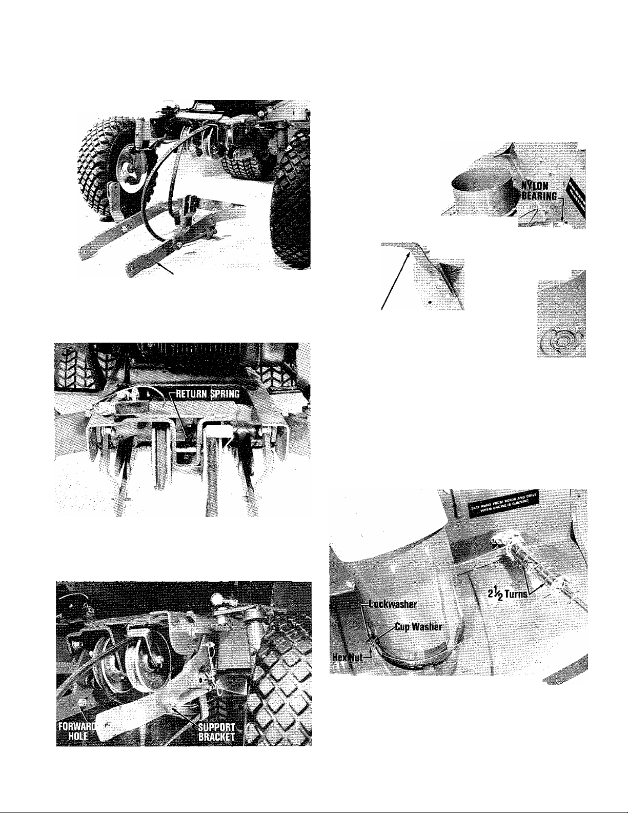
1. Disconnect the return spring between PTO idler pulleys.
Place belt around rotor drivepulley on the hitch assem
bly. Position hitch assembly under tractor (see photo).
■ c,
4. Secure rod guide support to body using the 3/8-16 x 1
hex head bolts, 3/8" lockwashers, and 3/8-16 hex nuts
supplied. Insert spout control rod into spout control
tube and secure with 1" cotter pin. Now insert spout
control rod assembly into nylon bearing on right side of
body and secure with two 3/4" cotter pins. Attach rod
guide and nylon liner to control rod and secure to rod
guide support arm with the hex head bolt, lockwasher and
hex nut (see photo).
Si
ROD GUIDE and
NYLDNLINER
4.
HITCH ASSEMBLY
Pass the belt over PTO idle pulleys through cutout in
crossmember and around lower engine pulley. Replace
the return spring previously removed and pull forward
all slack to left side of unit (see photo).
2. Secure hitch to tractor using clevis pins and quick pins.
Be sure to mount rear of hitch to the rear most holes in
the hitch support brackets. Check to insure support arm
assembly is mounted in the foward holes in hitch assem
bly (see photo).
X2 COTTER PINS
ROD GUIDE
SUPPORf
5. Lower spout over neck of discharge spout on body and
line up with slot in rear of spout neck. Rotate spout until
it faces forward and connect spout extension with carriage
bolt, hex cup washer and wing nut. Position -control rod
tube so that cable clamp faces side of discharge spout.
Loop wire cable on most forward part 2-1/2 coils counter
clockwise passing over the top of guide tube and secure
to stud on spout. Coil 2-1/2 times on rear of tube clock
wise passing under tube to spout and secure with special
cup washer, lockwasher and hex nut (sec photo).
3. Attach skidshoes to bodyusing the3/8-16 x 3/4carriage
bolts, 3/8" flat washers, 3/8" lockwashers and 3/8" full
hex nuts.
NOTE: HOOD REMOVED FOR
PHOTOGRAPHIC PURPOSES
Page 4
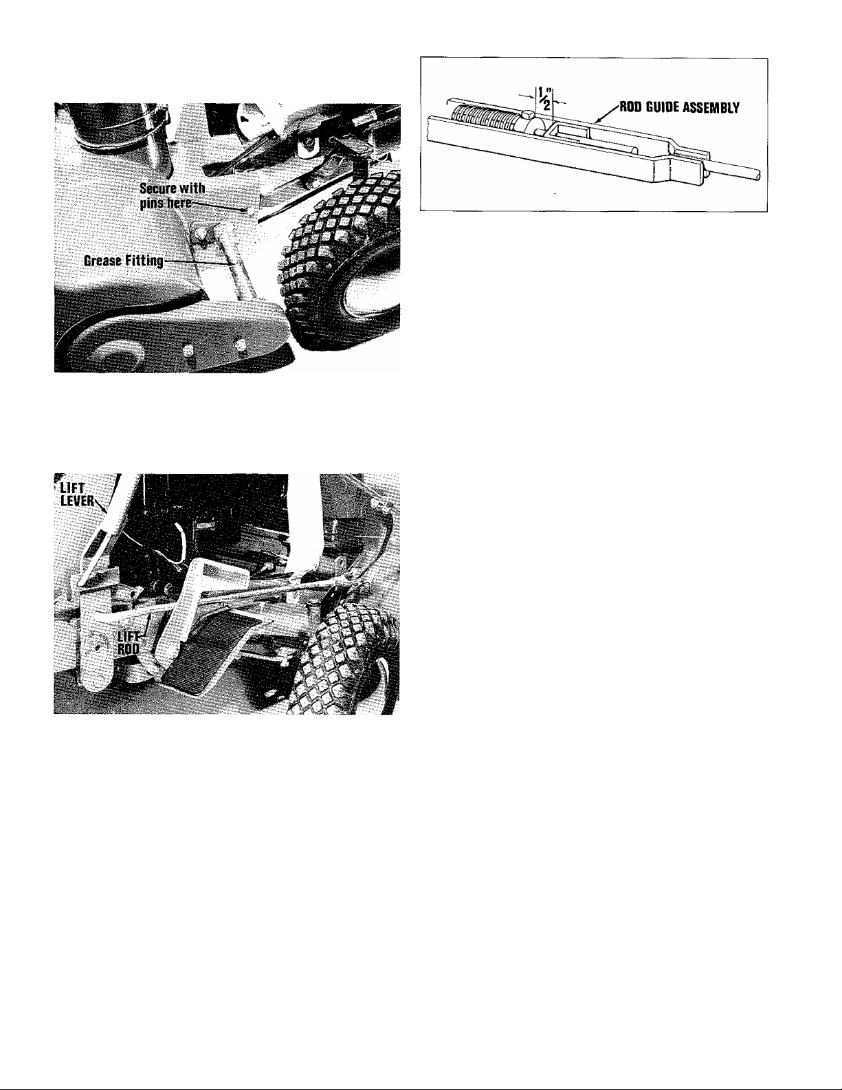
6. Position the snow thrower in front of^the tractor lining
up hitch with mounting holes in body and secure with
clevis pin and quick pin (see photo).
Place lift control handle in forward most position. In
sert lift rod into upper hole on lift control and secure
with quick pin. Loosen the lock nut and adjust clevis to
line up with mounting hole in rod guide support. Secure
with clevis pin and quick pin and tighten locknut (see
photo).
OPERATION
CHUTE DEFLECTOR POSITION
The chute deflector can be adjusted by loosening the wing
nuts and moving the deflector up or down. Be sure to tighten
both wing nuts after positioning the deflector. The chute
deflector position supplements the engine speed control to
control throwing distance. The highest position provides
the greatest throwing distance. Most snow moving can be
done with the deflector all the way up by using the engine
speed lever to control the throwing distance. Hold the rear
of the deflector down while tightening the wing nuts to make
sure all of the snow goes out the chute.
.f"'v
% -p.'
BELT ADJUSTMENT
The lower pulley on the hitch assembly may be moved for
ward or backward in the slotted hole for belt adjustment
purposes. Adjust this pulley so there is sufficient beltslack
for proper idling of the snow thrower.
Once proper belt slack for idling has been obtained, the PTO
spring must be checked and adjusted to give the proper belt
tension during operation. Proceed as follows:
1. Engage the PTO lever.
2. Measure the distance from the set collar to the rod guide
assembly. There should be 1/2” spacing between these
points. (See Figure)
It may be necessary to adjust the set collar to obtain the
1/2”. Be sure to disengage PTO lever first. Loosen the
set screw on the collar and reposition the rod in the collar.
Engage PTO lever and check again. Repeat this procedure
until the 1/2” is obtained.
SKID SHOE ADJUSTMENT
Gravel Surface Use Adjustment
The two skid shoes located on each side of the snow thrower
housing, should be lowered all the way down when operating
on a gravel surface. To adjust the skid shoes, raise the
snow thrower housing a couple of inches off the ground.
Loosen the two nuts and drop the skid shoes to the lowered
position. Set the bottom surface of the skid shoes so they
are level or slightly (maximum of 1/8”) higher in the front
and tighten nuts securely. Both skid shoes should be posi
tioned the same. The snow thrower will now be supported
on the skid shoes so the scraper bar can skim the snow from
the surface without picking up and throwing stones.
Hard Surface Use Adjustment
Loosen the two skid shoe mounting nuts and rest the snow
thrower on a hard level surface. The snow thrower should
now be supported by the tractor and the skid shoes with the
scraper bar resting on the ground surface. Tighten the nuts
on both skid shoes taking care that their position doesn’t
change while the nuts are tightened. The full width scraper
bar on your snow thrower will now get down to the ground
surface and scrape it clean.
OPERATING THE TRACTOR AND SNOW THROWER
Determining Snow Removal Pattern
Before beginning to remove snow from any area, the opera
tor should determine the best snow removal pattern. The
size, shape, terrain and obstructions of the area to be cleared
should be considered. Usually it is best to drive back and
forth the long direction of the area to minimize turning.
CAUTION: ALWAYS RAISE THE SNOW THROWER BEFORE
TURNING OR BACKING TO PREVENT DAMAGE TO IT.
Page 5

TRANSPORTING THE SNOW THROWER
Transport the snow thrower in the raised position with the
power take off control in the disengaged position. Ground
speed should be adjusted according to the type and condition
of the road surface. CAUTION: WITH THE SNOWTHROWER
INSTALLED ON THE TRACTOR, WEIGHT ON THE FRONT
WHEELS WILL BE SUBSTANTIALLY INCREASED MAKING
TURNING MORE DIFFICULT UNDER SOME CONDITIONS.
ENGINE SPEED
The tractor engine should normally be operated at 3/4 to
full speed when using the snow thrower. Operate it at full
speed when throwing deep or heavy snow. Less than 3/4
speed may be used in light snow if a short throwing distance
is desirable.
ENGAGING SNOW THROWER DRIVE
The tractor engine should be operating at 1/2 to 3/4 throttle
when the snow thrower is engaged. To engage the snow
thrower drive, push forward and down on power take off
lever. CAUTION: IF THE SNOW THROWER DRIVE
SHOULD BEGIN TO SLIP WHILE THE POWER TAKE
OFF IS ENGAGED, DISENGAGE THE POWER TAKE OFF
CLUTCH IMMEDIATELY TO PREVENT DAMAGE TO THE
SNOW THROWER DRIVE BELT OR POWER TAKE OFF
CLUTCH.
RAISING AND LOWERING THE SNOW THROWER
The snow thrower should be raised and lowered using the
tractor lift lever.
CONTROLLING GROUND SPEED
The best ground speed will vary greatly with the type and
amount of snow being thrown. For most conditions one to
two MPH will be a good starting speed. Refer to the opera
tion chart in your tractor owner's manual for speed control
settings to achieve the desired speed. Firstgear is normally
used for snow throwing.
THROWING DISTANCE
The snow should be deposited beyond the surface you want
to clear if at all possible. Start with the deflector all the
way up and adjust engine speed so that the thrown snow is
deposited just beyond the far side of the area to be cleared .
If the snow is only a couple of inches deep, it may be nec
essary to go over the ground quite rapidly to feed snow into
the auger. In this situation the deflector should be lowered
and the engine speed increased. CAUTION: STOP THE
ENGINE AND PLACE PTOIN NEUTRAL WHILE CHANGING
THE DEFLECTOR ADJUSTMENT.
THROWING DIRECTION
The spout control handle is used to rotate the snow thrower
spout to the left and right to control the throwing direction.
Whenever possible, begin snow removal on the upwind side
of the sidewalk or driveway so it is not necessary to blow
snow over an area already cleared.
The chute should be rotated to discharge the snow downwind,
not into it. Always adjust the spout and extension so that
you are well out of the path of the snow stream. CAUTION:
CONSTANT INHALATION OF COLD, WET VAPOR IS EX
TREMELY DANGEROUS. ON WINDY DAYS, HAVE YOUR
NOSE AND MOUTH COVERED UNLESS YOUR TRACTOR
IS EQUIPPED WITH A SNOW CAB.
MOVING THE SNOW
Light Snow
Snow up to 8” deep can usually be cleared in one pass the
full width of the machine. Face the snow thrower into the
snow, set the throttle at 1/2 speed or more and engage the
tractor power take off completely. When the auger drive is
fully engaged, readjust the engine speed as described under
Throwing Distance. Select the proper gear or transmission
speed control lever setting to give the speeds suggested
under Controlling Ground Speed. Drive the tractor and
snow thrower slowly into the snow. When you have come
to the end of a pass, raise the snow thrower and turn the
tractor around to make the next pass along side of the cleared
area. Allow about 2" of overlap into the cleared area.
Lower the snowthrower, rotate thechuteso thesnowstream
goes downwind, and engage the tractor drive for the second
pass. Repeat these steps until the area is cleared.
HEAVY DEEP SNOW
With very dense snow or snow deeper than the center of the
auger, a different method is necessary.
First Pass
Lower the deflector about 1/2 way and run the engine at full
speed. Raise the snow thrower until the top of the auger
housing is above the top of the snow whenever possible.
Engage the tractor drive gently, drive slowly through the
snow. Readjust the deflector if necessary to obtain the
desired throwing distance. Renieiiiber to stop the engine
before adjusting the deflector. At the end of the pass, turn
around as described under light snow, except go over the
same path with the snowthrower in the lowered position.
In some cases it may be better to back up every few feet
and clear the snow down to the ground surface, so the tractor
tires are not running in deep snow.
Subsequent Passes
Use the same procedure as for light snow, but substantially
increase the overlap into the cleared area. In other words,
take a narrower slice of snow than the width of the auger
housing. Judge how wide a slice to take by watching the
snow stream. It should continue to flow freely from the
chute. If it does not, slow the tractor ground speed or take
a narrower slice of snow. Any time snow stops flowing
freely from the spout, use reverse to back away until the
snow thrower clears itself and then inch slowly into the
snow. You will soon get the feel of how fast to go, and how
wide a slice to take.
FOREIGN OBJECT IN THE AUGER OR PLUGGED CHUTE
If the auger stalls or the chute plugs, disengage the tractor
power take off control immediately. Stop the engine, set
the parking brake and remove the foreign object or clear
the spout. Always stop the engine before working near or
on the auger or spout.
Page 6

STORING THE SNOW THROWER
After the clearing job is finished, the tractor should be
transported to a sheltered area,. When transporting the
snow thrower, always disengage the power take off, and
lift the snow thrower to the raised position. Place the
transmission and power take off control in the neutral po
sition and run the engine at slow speed for 5 minutes to
melt and dry up the snow in hidden areas to prevent icing.
ORDERING REPLACEMENT PARTS
Replacement parts required for maintenance services or
repair work should be purchased from your HOME LITE
dealer. When ordering parts, always furnish model and
serial number to dealer.
ACCESSORIES
MAINTENANCE
After Each Use
With the engine stopped and the PTO in "Neutral", inspect
the snow thrower for loose or missing bolts, pins and worn
or damaged parts. Check for any buildup of ice in the thrower
housing and around pulleys which may cause damage when
unit is started. Make any necessary repairs before using
the snow thrower again.
Every 15 Hours of Operation
There is one giease fitting located on the cross shaft. Wipe
off fitting and lubricate with a general purpose automotive
type grease. Apply a coating of grease on the chain every
15 hours of operation.
An occasional application of light motor oil should be applied
on all moving parts.
NOTE: Do not get oil or grease on belts or pulleys.
Once Each Year
Once each year or more often if the snow thrower is used
commercially, the drive chain should be inspected for wear
and adjustment. Proceed as follows:
1. Remove the two hex nuts and drive chain cover.
The following accessories can be purchased through your
HOMELITE dealer.
1. Four rear wheel weights.
2. Two front wheel weights.
3. 'Tire chains.
CHAIN
BEAR Stud
C0VER\^
HEX NUTS
LOCK WASHERS
2. Inspect the chain for wear and excessive slack. Replace
if worn.
To Adjust Chain:
1. Loosen the rear stud on the chain side plate.
2. Pull back on the crosspiece until all slack is taken out of
the chain.
3. Tighten stud and replace chain guard.
To remove and replace chain loosen rear stud and push for
ward on crosspiece until chain can be removed from smaller
sprocket. Install new chain and follow procedures for adjust
ing chain.
Page 7

TROUBLE
SHOOTING
TROUBLE
AUGER DOES NOT ROTATE
AUGER ROTATES BUT DOES
NOT THROW SNOW FAR
ENOUGH
SCRAPER BAR DOES NOT
CLEAN DOWN TO HARD
SURFACES
SNOW THROWER PICKS UP
AND THROWS STONES
WHEN USED ON GRAVEL
SURFACE.
TRACTOR DOES NOT HAVE
SUFFICIENT TRACTION
POSSIBLE SOLUTION
• PTO NOT ENGAGED.
• DRIVE BELT SLIPPING.
• ENGINE SPEED TO LOW.
• GROUND SPEED TOO FAST.
• CLOGGED DISCHARGE SPOUT,
• SKID SHOES NOT PROPERLY
ADJUSTED.
SKID SHOES NOT PROPERLY
ADJUSTED.
• ADD WHEEL WEIGHTS AND
TIRE CHAINS.
TRACTOR NOT STABLE ON
SLOPING SURFACES
HOMELIXr
PORT CHESTER, NEW YORK, U.S.A. 10573
• REDUCE GROUND SPEED.
• ADD WHEEL WEIGHTS
CHECK FOR CORRECT TIRE
INFLATION (OWNER’S MANUAL).
*laxtront
DIVISION
Page 8

BODY, ROTOR & DRIVE ASSEMBLY
No. Description
1
KEY-hi-pro
SCREW-hex cap, 5/16‘-18 x 5/8
2
ROTOR
S
DEFLECTOR
4
5 NUT-hex, 5/1G-18
WASHER-lock, 5/16
6
7
BODY
SCREW-set, 5/16-18 x 5/lG
8
KEY-Woodruff #9
9
10 PULLEY-drive
SCREW-hex cap, 3/8-16 x i
11
WASHER-flat, 3/8
12
SCREW-hex cap, 5/16-18 x 1-1/2
13
CLAMP-support assembly
14
15 BEARING-ncedle
WASHER
l(j
17 HOUSING-bearing
WASHER-lock, 3/8
18
NUT-hex, 3/8-16
19
FITTING-grease
20
8
Part No.
LM-01510-40
LM-09193-18
LM-01068-47
LM-01067-74
LM-09173-72
LM-0917 3-56
LM-01611-98
LM-09117-12
LM-09051-23
LM-01064-85
LM-09077-31
LM-09173-78
LM-09199-33
LM-01064-76
LM-01542-58
LM-80610-12
LM-0106 8-54
LM-09169-65
LM-09169-50
LM-09128-08
ALWAYS FURNISH MODEL AND SERIAL NUMBER WHEN ORDERING PARTS.
Qty.
1
4
1
1
12
12
1
2
1
1
1
4
2
2
2
1
1
7
7
1
N9.
'21
22
23
24
25
26
27 PLATE-side
28 NUT-hex lock, 3/8-16
29
30
31
32
33
34
35 WASHER-lock, 1/4
36 NUT-hex lock, 5/16-lS
37
38
39
40
Description
NUT-Range, 3/S-16
SKID
BOLT-carriage, 3/8-16 x 3/4
SHAFT
CHAIN
STUD
GUARD- chain
SPROCKET-rotor
SCREW-hex cap, 5/16-18x3/4
CARTRIDGE-bearing w/setscrew
FLANGE-bearing
NUT-hex. 1/4-20
SCREW-hex cap, 5/16-18 x 5/8
SCREW-hex cap, 1/4-20 x 5/8
SCRAPER-body
WASHER-1/2
Part No.
LM-09283-52
LM-01067-47
LM-09221-10
LM-01068-51
LM-01060-58
LM-01067-71
LM-01707-54
LM-09234-28
LM-01708-65
LM-01066-53
LM-09173-97
LM-01067-32
LM-01610-69
LM-09166-22
LM-09169-64 6
LM-09233-62 2
LM-09252-05
LM-09219-59
LM-01068-53
LM-09173-77
Qty.
2
2
4
1
1
2
1
2
1
1
6
2
4
6
2
6
1
2
Page 9

HITCH ASSEMBLY
1 PIN-yoke LM-01543 “OS 1
2 PIN-quick LM-09181-96 8
3 YOKE-end adjusting LM-0157 6-31 1
4 NUT-hex, 1/2-20 LM-09194-23 1
5 SCREW-hex cap, 3/8-16 x 3/4 LM-09081-27 1
6 PULLEY LM-01010-96 1
7 BELT-"V” LM-OiO82-09 1
8 WASHER-flat, 3/8 LM-09173-78 2
9 SPACER LM-01541-77 1
10 ARM-support LM-16072-22 2
11 PIN LM-01563-OG 6
12 SCREW-hex cap, 3/8-16 x 1 LM-09077-31 2
13 ROD-lift LM-16075-61 1
14 WASHER-loek, 3/8 LM-09169-65 1
15 NUT-hex, 3/8-16 LM-09169-50 ■ 1
16 ARM-push LM-16072-24 1
17 NUT-hex lock, 3/8-16 LM-09234-28 2
18 DEFLECTOR-heat LM-01612-96 1
19 FILM-shield LM-01702-52 1
DECAL-safety LM-01612-47 1
20 SCREW-hex cap, 3/8-16 x 1 LM-09077-31 2
21 NUT-hex, 3/8-16 LM-09169-50 2
22 WASHER-lock, 3/8 LM-09169-65 2
23 SUPPORT-spout adj. rod LM-16075-62 1
ALWAYS FURNISH MODEL AND SERIAL NUMBER WHEN ORDERING PARTS.
Page 10

24
/1
2»
SPOUT ASSEMBLY
'6 '®I4l3
No,
1 NUT-hex, 5/16-18 LM-09173-72 1
2 WASHER-lock, 5/16
3 WASHER-cup
4
5 WASHER-flat, 3/8
6 NUT-wing, 5A6-18
7
WASHER-lock, shakeproof, 3/8
8
BOLT-carriage, 5/16-18 x 3/4
SPOUT
9
10 CLAMP-cable
11
CABLE
12
NUT-hex, 1/4-20
13 WASHER-lock, 1/4 LM-09169-64 2
14
BEARING
15 SCREW-hex cap, 1/4-20 x5/8
PIN-cotter, 3/32 x 3/4
16
17
SCREW-Taptite, 1/4-20 x 3/8
18 TUBE-spout control
19 NUT-hex lock, 5/16-18
20 GUIDE-rod LM-01520-50
21 LINER-guide
22 SCREW-hex cap, 5/16-18 x 1-1/2 LM-09199-33 1
PIN-cotter, 5/32 x 1
23
24
HANDLE
Description
EXTENSION-spout
Part No.
LM-09173-56 1
LM-01713-79
LM-01067-60 1
LM-09173-78 2
LM-01062-29
LM-09287-10 2
LM-09205-62 2
LM-01067-62 1
LM-01713-82 1
LM-01713-62 1
LM-09166-22 2
LM-01064-91 1
LM-09077-27
LM-09184-47 2
LM-09274-28 1
LM-01068-09 1
LM-09233-62
LM-01211-75 1
LM-09184-55 1
LM-01066-06 1
Qty.
1
2
2
1
1
\s#'
10
ALWAYS FURNISH MODEL AND SERIAL NUMBER WHEN ORDERING PARTS.
Page 11

NUMERICAL PARTS LIST
Part No.
LM 01010 96
LM 01060 58 Chain w/conn, link
LM 01064 76
LM 01064 85
LM 01064 91
LM 01066 06 Handle Assembly
LM 01066 53
LM 01067 32 Bearing Cartridge
LM 01067 47
LM 01067 60
LM 01067 62 Spout Assembly
LM 01067 71
LM 01067 74 Deflector
LM 01068 09
LM 01068 47
LM 01068 51
LM 01068 53 Scraper-body
LM 01068 54
LM 01082 09 Belt-"V”
LM 01211 75
LM 01510 40 Key-hi pro
LM 01520 50
LM 01541 77
LM 01542 58
LM 01543 05
LM 01563 06
LM 01576 31
LM 01610 69 Flange -bearing
LM 01611 98 Body Assembly
LM 01612 47
LM 01612 96
LM 01702 52
LM 01707 54
LM 01708 65
LM 01713 62
LM 01713 82
LM 09051 23 Key-Woodruff #9
Description
Pulley-idler
Clamp-support
Pulley-drive
Bearing
Spro cket-rotor
Skid 2
Extension-spout
Stud 2 LM 09081 27
Tube Assembly
Rotor Assembly
Shaft Assembly
Housing-bearing
Liner-guide
Guide-rod
Spacer
Bearing-needle
Pin-yoke
Pin-rd.hd.-3/8X 1-1/2
Yoke-rod end
Decal-safety
Deflector-heat
Film-shield
Plate-side
Guard-chain
Cable Assembly
Clamp
Qty.
1
1
2
1
1
1
1 FASTENING PARTS
2
1
1
1
1
1
1
1
1
1
1
1
1
1
2
1
6 LM 09194 23
1
4
1
1
1
1
1
1
1
1
2 LM 8Ó610 12
Part No.
LM 09128 08
LM 09181 96
LM 16072 22
LM 16072 24
LM 16075 61
LM 16075 62
LM 01062 29
LM 01713 79
LM 09077 27
LM 09077 31
LM 09117 12
LM 09166 22
LM 09169 50
LM 09169 64
LM 09169 65
LM 09173 56
LM 09173 72
LM 09173 77
LM 09173 78
LM 09173 97
LM 09184 47
LM 09184 55
LM 09193 18
LM 09199 33
LM 09205 62
LM 09219 59
LM 09221 10
LM 09233 62
LM 09234 28
LM 09252 05
LM 09274 28
LM 09283 52
LM 09287 10
Description
Fitting-grease
Pin-quick
Arm Assembly-support 2
Arm Assembly-push 1
Rod-lift
Support-spout adj. rod
Nut-wing, 5/16-18
Washer-cup
1/4-20 X 5/8
3/8-16 X 1 5
3/8-16 X 3/4
5/16-18 X 5/16
Nut-1/4-20
Nut-3/8-16
Washer-lock, 1/4
Washer-lock, 3/8
Washer-lock, 5/16
Nut-5/16-18
Washer-flat, 1/4
Washer-fiat, 3/8
5/16-18 X 3/4
Pin-cotter, 3/32 X 3/4 2
Pin-cotter, 5/32 x 1
5/16-18 X 5/8
Nut-hex, 1/2-20
5/16-18 X 1-1/2 3
Bolt-5/16-18 X 3/4
1/4-20 X 5/8
BoU-3/8-16 X 3/4
Nut-hex, 5/16-18
Nut-hex, 3/8-16
5/16-18 X 5/8
1/4-20 X 3/8
Nut-flange, 3/8-16
Washer-lock, 3/8
Washer
Qty.
1
8
1
1
2
1
2
1
2
8
10
8
10
13
13
2
8
6
1
4
1
2
6
4
3
4
2
1
2
2 .
7
ALWAYS FURNISH MODEL AND SERIAL NUMBER WHEN ORDERING PARTS.
11
Page 12

\ ,
PRINTED IN U.S.A,
HOMELITT
* tMttronI
PORT CHESTER, NEW YORK, U.S.A. 10573
DIVISION
E1271EZ
 Loading...