

Page 1
PARTS LIST
& INSTRUCTIONS
I io
38” LAWN REVITALIZER
HOMELITE'
DIVISION, PORT CHESTER, N-Y, 10573
textronl
Part No. 24683
Page 2

TABLE OF CONTENTS
INSTALLATION
....................................................................
OPERATION......................................................................... 4
DEPTH ADJUSTMENT.................................................... 4
PREPARATION FOR OPERATION
................................. 4
ENGAGING THE REVITALIZER ..................................... 4
TRAVEL SPEED AND DIRECTION
...............................
4
PREPARING A SEED BED.............................................. 5
REMOVING THE THATCH.............................................. 5
troubleshooting
...........................................................
ADJUSTMENTS ................................................................. 5
BELT TENSION ADJUSTMENT
BELT STOP ADJUSTMENT
DRIVE CHAIN ADJUSTMENT..
MAINTENANCE
..............
.....................................................
......................................
............................................
.....
.................................
AFTER EACH USE.......................................................... 7
AFTER 10 HOURS
ONCE EACH YEAR
BELT REPLACEMENT
..........................................................
.......................................................
....................................................
7
PROTECT YOURSELF AND OTHERS
1. Read and be familiar with the owners manual for your
tractor and the owners manual for the revitalizer before op
erating the revitalizer.
2. Do not allow anyone to use the revitalizer unless they have
been instructed in how to operate it safely.
3. Never attempt to adjust, repair or service the revitalizer
while the tractor engine is running.
4. Do not allow others near the revitalizer when it is operat
ing.
5. Stay clear of the drive belt, revitalizer knives and other
moving parts when the tractor engine is running.
3
5
5
5
6
^
7
^
f I
We warrant this HOME LITE product to be free from defects in material or workmanship under normal use and
service, except that we make no warranty, express or implied, with respect to tires, engines, generators or voltage
regulators (which usually are warranted by their respective manufacturers} nor with respect to any unit which
after sale by HOMELITE has been altered in any way without HOM ELITE'S express consent.Our obligation under
this warranty is limited to replacing, without charge any part which is proven defective within one year (30 days
if the unit is used for commercial, rental or municipal purposes) from date of purchase, if returned to us, with
transportation charges prepaid, at a HOMELITE branch office or to a dealer whom we have authorized to make
the replacement.
THIS WARRANTY IS IN LIEU OF ALL OTHER WARRANTIES, EXPRESS OR IMPLIED, OF MERCHANT
ABILITY, FITNESS FOR A PARTICULAR PURPOSE, PERFORMANCE OR OTHERWISE AND IN NO EVENT
SHALL HOMELITE BE LIABLE FOR ANY INCIDENTAL, SPECIAL OR CONSEQUENTIAL DAMAGES.
REQUIRED ACCESSORIES
Rear Lift Kit No, LM-16001-61 for Tractor Models
T-10, T-12 & T-15.
WARRANTY
HOMELITE
a divisian tif Textron Inc.
RECOMMENDED ACCESSORIES
Electric Lift Kit No, LM-16 001-78 for Tractor Models
T-10, T-12 & T-15.
Page 3
INSTALLATION
I ;
CAUTION: DO NOT ATTEMPT TO INSTALL OR WORK
ON THE REVITALIZER WHEN THE TRACTOR ENGINE
IS RUNNING.
1, Position the revitalizer behind the tractor.
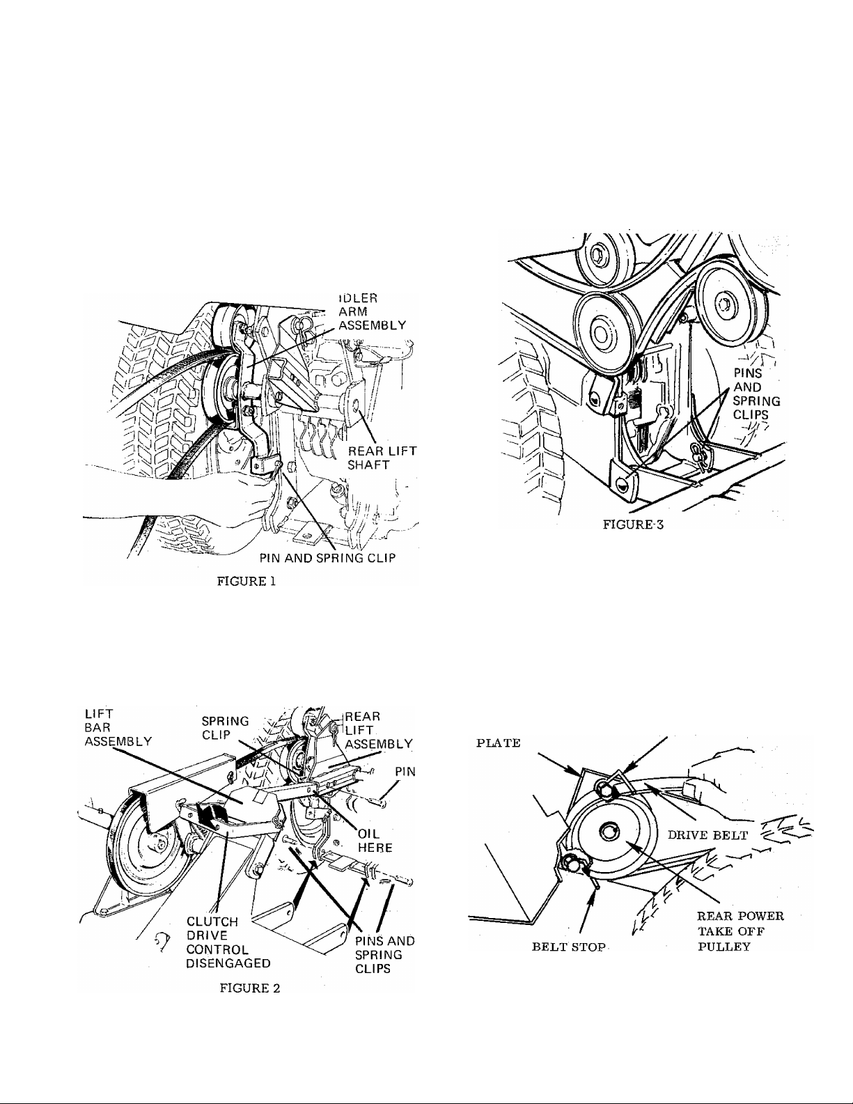
2. (See figure 1) Slide the idler arm assembly onto the left
end of the rear lift shaft. Attach the lower end of the idler
arm assembly to the hitch member with a pin and spring clip.
slide in place more easily. Fasten the lift bar in place with the
pin and spring clip provided.
4. (See figure 3) Move the tractor lift to the raised position.
Connect the revitalizer frame assembly to the tractor with 2
pins and spring dips.
3. (See figure 2) Lower the tractor lift unit and place the re
vitalizer lift bar assembly into the tube of the tractor rear lift
assembly. Placing a thin film of oil on the lift bar will make it
5. (See figure 2) Insure that the revitalizer drive dutch is
pushed all the way back in the disengaged position.
6. (See figure 4) Install the revitalizer drive belt over the rear
power-take-off pulley of the tractor. If-this pulley and the
belt'stops shown in figure 4 have not been previously installed
for use with the revitalizer or rotary tiller, see item (7) and
figure (12) of belt replacement in the Maintenance section of
this manual for proper positioning.
SIDE MOUNTING
BELT STOP
FIGURE 4
Page 4
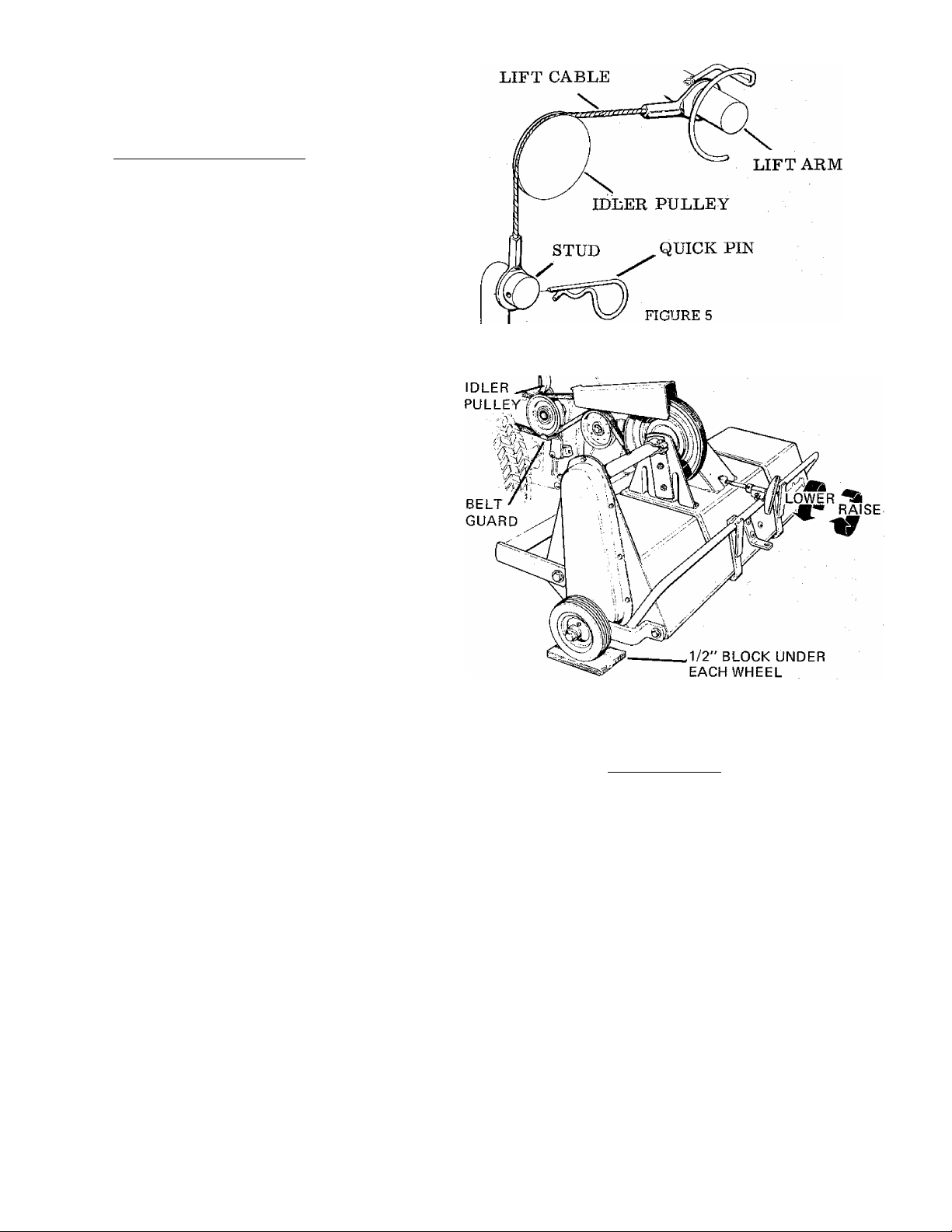
7. (See figure 5) If the mower is to be used with the revitalizer, remove the lift chain or cable from the tractor lift arm
when operating. This is especially beneficial in reducing lift
ing effort on tractors not equipped with power lift since the
revitalizer should be raised when turning to prevent excess
lawn damage. It is not advisable to raise the mower when
turning if the mower is engaged since operating the mower
in the raised position will reduce the life of the mower drive
belt.
8. Prior to first use or if the revitalizer has not been used re
cently, all adjustments listed in the Adjustments section of
this manual except the drive chain adjustment should be
checked before operating the revitalizer.
OPERATION
The HOMELITE Lawm Revitalizer is most effective if used in
the Spring and Fall of the year. In the Spring its use will lift
out thatch that harbors fungus and create a miniature irriga
tion system so that the water, fertilizer and air can reach the
grass roots. Use the Revitalizer pnce in the Spring between
the time the grass has started to grow vigorously and the time
when summer weather might be expected to slow grass
growth.
Used in the fall, the revitalizer will raise the summers accumu
lation of thatch and create a series of grooves which permit
frost to expand the soil for greater porosity. The grass roots
vrill have a better chance to expand during the next growing
season.
For best results the grass should be mowed to a length of
about 2 inches before the revitalizer is used. This will prevent
long grass from interfering with the revitalizing process.
Depth Adjustment
CAUTION; ALWAYS INSURE THE TRACTOR ENGINE
IS STOPPED BEFORE ATTEMPTING TO ADJUST OR
WORK AROUND THE REVITALIZER.
(See figure 6) Adjust the depth with the Revitalizer in the
lowered position. The cutting depth of the revitalizer knives
may be precisely adjusted by turning the T handle at the rear
of the revitalizer clockwise to raise the knives and counter
clockwise to lower them. For use in Spring and Fall as recom
mended, the knives should be set about 1/2 inch deep. The
1/2 inch depth may be set quite easily and accurately on a
level surface by placing a 1/2 inch block under each of the re
vitalizer guide wheels. BE SURE THE TRACTOR ENGINE
IS STOPPED. With the revitalizer clutch disengaged for ease
of turning, alternately rotate the drive pulley on the revital
izer and turn the depth adjusting handle until the ends of the
knives just hit the ground surface. The revitalizer should now
be set at 1/2 inch cutting depth. The grooves in the ground
may also be checked after operating a short distance to in
sure the correct depth setting.
Preparation for Operating
With the revitalizer (and mower if attached) disengaged and
in the raised position, move to the area to be revitalized. The
FIGURE 6
mower may be used with the revitalizer if the grass is notlong
or wet as to require full engine power for mowing. When
using the revitalizer it should be raised when turning to pre
vent excessive uprooting of grass, but it is neither advised nor
necessary to raise the mower. This may best be accomplished
by disconnecting the mower lift cable from the lift lever by
removing the spring clip and pin. See step 7 of Installation
instructions.
Engaging the Revitalizer
(See figure 7) The Revitalizer drive is engaged by pulling for
ward on the clutch lever mounted on the revitalizer. This can
be done from the tractor seat simply by reaching around and
pullir^ the clutch ahead. The revitalizer will be disengaged if
the lever is pushed back, away from the tractor.
Travel Speed and Direction
The revitalizer should be used with the tractor engine at
3/4 to full speed. Operating conditions will determine the
best ground speed. Under normal conditions where the
ground is smooth and soft a speed of 2 to 4 miles per hour’
should be satisfactory. This speed range will be approx
imated using 2nd gear, hi range on the dual| rangetrans-
Page 5

FIGURE 7
mission or 1/3 to 1/2 speed with the Hydrostatic Trans
mission, If the ground is hard, rocky or rough, a slower
speed may be advisable since the revitalizer will not be
as effective under these conditions.
Travel the long direction of the lawn to minimize turns. Be
fore turning, raise the revitalizer to prevent excessive uproot
ing of grass. On the second and successive passes, be sure to
drive so the revitalizer slightly overlaps that portion of the
lawn already revitalized.
NOTE: DO NOT MAKE SHARP TURNS WITH UNIT IN
GROUND, SINCE THIS WILL CAUSE LAWN DAMAGE.
If wire or other foreign material get caught in the revitalizer,
stop the tractor and disengage the clutch immediately. STOP
THE TRACTOR ENGINE BEFORE ATTEMPTING TO
WORK AROUND THE REVITALIZER.
Preparing a Seedbed
The revitalizer may be used to prepare a seedbed for reseed
ing a sparse area by making a second pass diagonally to the
first one at about a 45° angle. Use a depth setting of ap
proximately 1/2 inch.
Removing the Thatch
Dead g*ass and thatch should be removed after using the re
vitalizer. A HOMELiTE vacuum collector system is excellent
for this purpose. For best results allow the thatch and grass to
dry for a few hours before using the vacuum collector. A
sweeper will also work well in removing the thatch.
Trouble Shooting
If the thatch is not being lifted effectively:
1. Ground speed may be too fast - use a lower ground
speed.
2. Engine speed may be too slow - operate the engine at
3/4 to full throttle.
3. Long grass may be interfering - grass should be cut to
about 2” before revitalizing.
4. The revitalizer drive belt may be slipping - check the
belt tension to be sure it is set correctly, see Adjust
ments. Page 5.
If thatch removed is not uniform or an unusual amount of
green grass is being torn up:
1. Check to see if wire, sticks, etc. are caught on the
knives.
2. Check the depth of the grooves in the ground. A depth
of 1/2 inch is correct under most conditions.
If the drive belt will not stop turning when the revitalizer is
disengaged:
1. The belt stops may be out of adjustment. See “Ad
justments.” Page 5.
2. The belt tension adjustment at the revitalizer clutch
may be out of adjustment. See “Adjustments”. Page 5.
3. The belt may be of the wrong length or construction use only the correct belt.
O
ADJUSTMENTS.
Belt Tension Adjustment
(See figure 7) Tension on the revitalizer drive belt is regu
lated by the position of the set collar in the rod guide assem
bly of the revitalizer clutch. Belt tension is correct when there
is 5/8” to 3/4” clearance between the set collar and the lower
end of the rod guide assembly when the revitalizer clutch is
engaged. To increase belt tension, disengage the revitalizer
clutch and loosen the set screw in the collar. Move the rod
down slightly to reposition it under the set collar and re
tighten the set screw. Check the clearance by engaging the re
vitalizer clutch. Do not operate the revitalizer with more than
3/4 inch clearance between the set collar and rod guide as the
excessive tension may cause premature belt and bearing fail
ure.
Belt Stop Adjustment
If the revitalizer will not disengage properly or the back
side of the drive belt shows wear, the belt stops and guard
may need adjusting. Adjustments should be made as
follows.
CAUTION: DO NOT ATTEMPT TO MAKE ANY ADJUST
MENTS WITH THE TRACTOR ENGINE RUNNING.
(See Figure 8.) The belt stops are located above and be
low the drive pulley.
Page 6

I M— 16 0 6 0— 1 4
Pj,'
FIGURE 8
1. The belt stop located above the drive pulley is mounted
on the top mounting screw of the bevel gear case with
a special cap screw which replaces the original. This
belt stop should beadjusted to 1/4” clearance as shown
in Figure 8.
2. The belt stop located below the drive pulley is mounted
with a cap screw, flat washer, lock washer and hex nut
to the side mounting plate of the bevel gear case.
3. While holding the cap screw with a wrench so it will
not turn, loosen the nut located on the other side of the
mounting plate {see Figure 12) enough so the belt stop
can be moved. Adjust the belt stop so there is l/l6”
to 1/8” clearance between it and the revitalizer drive
belt.
4. To prevent the belt stops from moving, use a wrench
to hold the cap screw from turning while tightening the
nut inside the frame securely.
(See figure 7) The belt guard mounted over the revitalizer
drive belt should be adjusted so there is at least 1/8” clear
ance between the guard and the belt when the revitalizer
clutch is engaged to assure the backside of the belt does not
rub against the guard. If it is necessary to adjust the guard,
loosen the two wingnuts and reposition the guard correctly.
1. (See figure 9) With the chain cover removed so the chain
is visible, loosen, but do not remove the two bolts holding
each end of the bearing housing.
2. Pull upward on the bearing housing until, all slack is re
moved from the chain. Before tightening the bolts at each
end of the bearing housing, insure that the bearing housing is
parallel to the revitalizer housing. This may be easily and ac
curately done by measuring the distance from the bearing,
housing to the revitalizer housing at each end of the bearing
housing. When the two distances are equal, the bearing hous
ing is parallel to the revitalizer housing. (See figure 9).
After insuring all slack has been removed from the chain and
the bearing housing is parallel to the revitalizer housing,
tighten the two adjustment bolts at each end of the bearing
housing securely.
Put a liberal coating of automotive grease on the chain and
replace the chain cover.
GREASE
FITTING
LOOSEN HARDWARE
TO ADJUST CHAIN
BEARING HOUSING MUST
BE PARALLEL WITH
REVITALIZER HOUSING
CHAIN IS
CORRECTLY
ADJUSTED
WHEN ALL
SLACK HAS
BEEN
REMOVED
Drive Chain Adjustment
If inspection reveals that there is slack in the drive chain or it
must be replaced, use the following procedure to tighten the
chain:
GREASE FITTING
FIGURE 9
C
Page 7

0
CAUTION: ALWAYS BE SURE THE TRACTOR ENGINE
IS STOPPED BEFORE ATTEMPTING TO WORK AROUND
THE REVITALIZER.
After Each Use
Each time the revitalizer is used the knives should be checked
for wire or other material which may be caught in them.
Clean any foreign material away from the knives for best
operation. _
Every 10 Hours
There are five grease zerks located on the revitalizer which
should be lubricated with automotive grease after every 10
hours of use. They are located one on each of the two guide
wheels, one on each of the two tine shaft bearings and one on
the crossdrive housing. (See figure 9 and 10.) Lubricate each
zerk with 5 shots of grease or until grease is pushed out
around the bearings.
OIL
FIGURE 11
ON BOTH WHEELS
FIGURE 10
Lubricate all pivot points with engine oil to help prevent
wear. (See figure 11) Do not get oil on the drive belt OF the
pulleys.
Once Each Year
Once a year remove the chain cover on the left side of the re
vitalizer housing and inspect the chain. If the chain shows
excessive wear, it should be replaced. See your dealer for
the correct chain.
If the chain is loose it should be tightened until all slack is
removed. (See Adjustments).
Coat the chain liberally with automotive grease and replace
the cover.
Belt Replacement
If the revitalizer drive belt should become excessively frayed
or twisted or break and replacement is necessary, do the
following:
1. Be sure the tractor engine is not running.
2. Place the revitalizer clutch in the disengaged position.
3. (See figure 7) Remove the two wingnuts holding the belt
guard in place over the drive belt. Remove the belt guard.
4. (See figure 6) Remove the belt guard and idler pulley
from the reverse idler assembly and replace the damaged belt
with a new belt.
5. When replacing the belt guard, position it so the belt will
not rub against it when the revitalizer is operated.
6. (See figure 7) Place the new belt over the revitalizer pul
ley and replace the belt guard.
Page 8

7. (See Figure 12.) Check power-take-off pulley on the
tractor to be sure it is properly installed with the hub
facing in toward the tractor. Align the drive pulley with
the pulleys on the revitalizer, be sure that these pulleys
are in direct line. The key must be in place and the set
screw on the pulley hub tightened securely (see also
Figure 4).
Page 9

32
25
No.
1
2
3
Desciiption
SCREW-hex cap, 7/16-14 x l-^l/4
WASHER-flat, 3/8
SPACER
4 CLIP-spring
5
HANDLE-clutch-
6
NUT-hex jam, 7/16-14
WASHER-lock, '7/16
7
8
SCREW-set, 1/4-20 x 3/8
9
COLLAR-set
10 SPRING
11
ROD-clutch
12
GUIDE ASSEMBLY-rod
13 NUT-wing, 5/16-18
14 GUARD-belt
15
BOLT-carriage, 5/16-18 x 3/4
16
LEVER ASSEMBLY-clutch
17 NUT-hex, 3/8-16
18
WASHER-lock, 3/8
19
NUT-hex, 5/16-18
WASHER-flat, 5/16
20
21
SUPPORT-belt guard
22 SPACER-
Part No.
LM-09164-32
LM-09173-78
LM-01053-46
LM-01067-87
LM-01053-03
LM-09182-13
LM-09181-99
LM-0903S-07
LM-81910-22
LM-01620-65
LM-01053-43
LM-01584-06
LM-07180-06
LM-01053-26
LM-09205-62
LM-01052-95
LM-09169-50
LM-09169-65
LM-0923 3-62
LM-09176-42
LM-01053-59
LM-01053-39
ALWAYS FURNISH MGPEL AND SERIAL NUMBER WHEN ORDERING PARIS-
Qty.
1
3
2
6
1,
2
2
1
1 31 KEY LM-S0610-81
1
1
1
2
1
2'
1
4
4
1
3
1
1
No.
23 WASHER-flat, 7/16 LM-09J84-30 2
24 SCREW-hex cap, 7/16-14 x 3-1/2 LM-07150-93 1
25 KEY-Woodruff, #9.
26
27 SCREW-hex cap, 3/8-16 x 1-1/4 LM-,09174-00 2
28
29 BELT-"V", 12 hp.
30 STOP-belt
32
33
34
35
36 PULLEY-idler
37 PULLEY-idler
38 SCREW-hex cap, 3/8-16 x 7/8
39 GUARD-belt '
40
41 ARM ASSEMBLY-idler LM-01053-22
42
43
Description
PULLEY
PULLEY
SCREW-hex cap, 7/16-14 x 1-1/4 LM-09234-71
SCREW-hex cap, 3/8-16 x 1 LM-09077-31
STOP-belt
PULLEY LM-01642-02
PIN
BAR ASSEMBLY-lift
PIN
Part No.
Qty.
LM-09051-23 1
LM-010^3-02
LM-01053-06 1
LM-01053-40 1
LM-16060-14
LM-01670-32
LM-01053-80 1
LM-01640-83 1
LM-09193-57 1
LM-01053-51
LM-01563-06 1
LM-16074-25 1
LM-01180-53 i
1
1
1
1
1
1
1
1
1
Page 10

3
No. Description
1 CHAIN-drive
SHAFT ASSEMELY-drive LM-01723-40
2
3 WASHER
4
FITTING-grease (Hemite #1952) LM-07270-13
5 . HOUSING & BEARING ASSEMBLY
Includes:
6 BEARING-needle
7 ■ WASHER
8 WASHER-lock, 7/16
9 NUT-hex jam, 7/16-14
10
HOUSING ASSEME LY LM-01723-07
11 SCREW-hex cap, 5/16-18 x 5/8
12
SUPPORT-bearing
13
SUPPORT ASSEMBLY-clamp LM-01728-95
14 SCREW-hex cap, 5/16-18 x 1-1/2
15 BOLT-carriage, 7/16-14 x 1
16 WASHER-lock, 5/16
17 NUT-hex, 5/16-18
18 PLUG-button
19
SCREW-hex Taptite, 1/4-20 x 3/8
10
ALWAYS FURNfSH MODEL AND SERIAL NUMBER WHEN ORDERING PARTS.
Part No.
LM-01728-91
LM-01060-69
LM-01729-06
LM-01727-47
LM-01010-22
LM-09181-99
LM-09182-13
LM-09193-18
LM-01722-52
LM-09199-33
LM-07020-25
LM-09173-56
LM-09173-72
LM-01729-34
LM-09274-28
Qty. No.
1
1
1 22
1 23
1
2
1 27
4 28
4
1 30
2 31
1 32
2 33 SCREW-hex cap, 5/16-18 x 1/2
2
4
4
3
1
8
20
21
24
25
26
29
Accessories:
SPRAY CAN-blue, 14 oz. LM-16076-89 1
SPRAY CAN-black. 12 oz. 22772 1
Description Part No.
GUARD-chain
NUT-special, 5/16-18 LM-092 5 7-63 1
GUARD-trash
FLANGE-hearing
BEARING
FLANGE-bearing
WASHER-hex
SCREW-hex Taptite, 5/16-18 x 1/2
SHAFT ASSEMBLY-tine
TINE
SPACER
SPRING
WASHER
Qty.
LM-0172 9-83 1
LM-01728-74 2
LM-01729-73 2
LM-01723-47
LM-01729-72
LM-01723-32 4
LM-0924 8-56
LM-01723-38 1
LM-01703-33 14
LM-01703-37 12
LM-01704-17
LM-01231-44 1
LM-09193-17 1
2
2
6
1
Page 11

:W
HITCH AND HEIGHT ADJUSTMENT
1
No. Description
1 HITCH ASSEMBLY
2 ADJUSTER
3 PIVOT
4 WASHER-flat, 5/16
5 PIN-cotter, 3/32x3/4 LM-09184-47
Part No. Qty.
LM-16 074-44 1
LM-01722-71 1
LM-01081-72 1
LM-09176-42 1
1
6 COLLAR-set LM-01052-01 1
7 SCREW-set, 1/4-20 X 5/16
8
LENER-guide .LM-01211-75 1
9 GUIDE-rod LM-01520-50 1
10 WASHER-fiat, 3/8
11
SCREW ASSEMBLY-adjusting LM-01084-15 1
12
NUT-hex, 5/16-18
13
SCREW-hex cap, 5/16-18 x 1-1/4 LM-09077-29 1 30
14
BOLT-carriage, 5/16-18 x 3/4
15
REINFORCER-tow bar LM-01723-16 1
16
WASHER-lock, 5/16
17
NUT-hex, 5/16-18 LM-09173-72 4
LM-07135-05 1
LM-09173-78 3
LM-09233-62 1
LM-09194-14 3
LM-09173-56 4 ■
No. Description Part No.
18 BOLT-carriage, 5/16-18 x 1 LM^ 09211-58 1
19
BAR-tcw
20 NUT-hex, ,3/8-16
WASHER-lock, 3/8
21
22
SPACER LM-01183-35 2
SCREW-hex cap, 3/8-16 x 1-1/4
23
24 NUT-hex, 7/16-14 LM-07175-19 2
25 WHEEL & TIRE ASSEMBLY LM-16062-55
26
BOLT-wheel
27 NUT-hex, 1/2-13
28
WASHER-flat, 1/2 LM-09184-31 4
29 SPACER LM-01053-86 2
SCREW-hex cap, 1/2-13 x 1-1/4
31 PIN LM-01550-37
32 CLIP-spring LM-01067-87 2
DECAL-safety (not shown) LM-01030-31 1
LM-01723-17
LM-09169-50- 2
LM-09169-65 2
LM-09174-00 2
LM-01726-82 2
LM-07175-18
LM-09172-79 2
Qty.
1
2
2
2
ALWAYS FURNISH MODEL AND SERIAL NUMBER WHEN ORDERING PARTS;
11
Page 12

%
o
Printed in U. S, A.
HOMELITr
«text ran I
PORT CHESTER, NEW YORK, U.S.A. 10573
DIVISION
w'
E1271EZ
 Loading...