

Page 1

INSTRUCTDNS
& PARTS LIST
HOMELITE
■ ■ ■■■
®
O
56 ROTARY
TILLER
II*
PART NO. 24666
Page 2

Read the Owner's Manual carefully. Be thoroughly
familiar with the controls and proper use of the
equipment.
Never allow children to operate the unit.
■ Disengage power to attachments when transporting or
not in use.
■ Do not change engine governor settings or overspeed
engine.
Keep the area of operation clear of all persons, particu
larly small children, and pets.
Thoroughly inspect the area where the equipment is to
be used and remove all stones, wire, bones and other
foreign objects.
Do not operate equipment when barefoot or wearing
open sandals. Always wear substantial footwear.
Check fuel before starting engine. Do not fill gasoline
tank indoors, when engine is running, or while engine is
still hot. Wipe off any spilled gasoline before starting
engine.
TINE WARRANTY
■ Do not put hands or feet near or under rotating parts.
■ Stop tines when crossing gravel drive, walks or roads.
■ Vehicle and attachments should be stopped and inspected
for damage after striking a foreign object and the damage
should be repaired before restarting and operating the
equipment.
■ If the equipment should start to vibrate abnormally, stop
the engine (motor) and check immediately for the cause.
Vibration is generally a warning of trouble.
vT’'n"^S
HOMELITE warrants rotary tiller tines against breakage for the period not to exceed
the normal life of the rotary tiller: and will replace broken tines directly to the customer
at no charge, provided broken tines are returned prepaid to the nearest HOMELITE
district office.
HOMELITE
a division of Textron Inc.
CONTENTS
SAFETY............................................................................................................................... 2
HOMELITE
A tgXtfOnI DIVISION, POUT CHESTER. N.T. !OS73
//
36 R OT A RY TI L LE R
WARRANTY..................................................................................................................... 2
INSTRUCTIONS.............................................................................................................. 3
LUBRICATION ............................................................................................................... 3
BELT ADJUSTMENT...................................................................................................... 3
PARTS
HOUSING GROUP........................................................................................................ 4
DEFLECTOR & TINE GROUP..................................................................................... 6
TILLER DRIVE GROUP................................................................................................. 8
TINE EXTENSION GROUP..................................................................................... 10
PARTS LIST.................................................................................................................... 11
Page 3

ASSEMBLY INSTRUCTIONS BELT ADJUSTMENT
1. Position tiller at the rear of the tractor. Place the lift
lever in the fully back position. Put the tiller lift assem
bly into the tractor lift assembly and secure with clevis
pin and quick pin.
fe(
2. Place tractor lift lever in forward position. Secure the
tiller frame assembly to tractor with the two clevis pins
and two quick pins supplied.
The belt that transmits power from the bevelgear box to the
tiller drive shaft is designed to provide long and satisfactory
service. Because of the special design of this belt, it is
urged that it is only replaced with genuine replacement
ordered from your dealer.
Adjustment of belt tension is controlled by the set collar on
the rodguide assembly. The tensionshould be correct when
there is about 1-1/4" clearance between the collar and the
bracket of the rod guide assembly with the tiller clutch lever
engaged. To increase the tension, release the tiller clutch
lever and loosen the setscrew in the collar. Slide the collar
up toward the spring and retighten the set screw. Check
the tension by engaging the tiller clutch lever. Avoid ex
cessive tension as it will cause premature belt failure.
3. Slide idler arm assembly onto rear lift shaft.
4. Attach lower end of idler arm assembly to hitch member
with clevis pin and quick pin.
5. Assemble pulley to power take-off (PTO) shaft on bevel
gear housing. Using existing cap screw, washers, and
nut, secure belt stop to tractor.
6. Position belt dh pulleys and check that the belt is seated
properly in the pulleys, and that the pulleys are properly
aligned.
LUBRICATION
There are grease fittings on each housing bearing and two
90° grease fittings are on the right hand side of the housing.
These fittings should be lubricated every three hours of
operation. Use a good grade of general purpose automotive
type grease applied with a standard grease gun. (Fittings
should be wiped clean before applying any grease.) Also
apply a few drops of lubricating oil to the moving linkages
of the tiller drive assembly occasionally.
Before starting the tractor engine, place the tiller clutch
lever in the disengaged position, and raise the tiller above
the surface of the ground. With the tractor engine running,
engage the tiller clutch and lower the tiller into contact
with the ground. As the tiller works into the soil, slowly
release the tractor clutch and move ahead. When coming
to the end of a row, raise the tiller free of the ground be
fore turning around.
Effective operation of the tiller will depend in a large degree
upon the operator. For example; when intending to till a
sod area into a seed bed for gardening, it obviously will re
quire several passes over the same path to break the sod
and ground into fine particles suitable for a seed bed. De
pending on the nature of the soil, it will be desirable to altar
the depth settings for the tiller on succeeding passes until
the desired depth is reached. When tilling in soil that has
been previously worked, it may be possible to till to the de
sired depth from the start.
The depth of tilling is regulated by the ground speed of the
tractor. The slower the ground speed the deeper the tilling
action.
NOTE: When using the rotary tiller on a tractor
equipped with the power lift attachment,
the power lift attachment must be in the
float position. Operating the tiller in the
hold position will cause the tiller tines to
propel the tractor at a dangerous speed .
Page 4

HOUSING GROUP
I
Page 5

No.
Description Part No. Qtj
FITTING-grease
1
2
BOLT-(R. H. side)
WASHER-lock, 1/2
3
SIDE BAR
4
NUT-full hex, 5/16-18
5
WASHER-lock, 5/16
6
BEARING
7
LCXiKNUT-full hex, 5/16-18
8
9
HALF CASE ASSEMBLY (R. H.)
NUT-full hex, 1/2-13
10
WASHER-flat, 1/2 LM-09184-31
11
SCREW-thread forming,
12
3/8-16 X 1-1/2
13
BEARING
14
SEAL
15 UPPER BEARING PLATE
ASSEMBLY
Includes: (each assembly)
16
17
SCREW-hex cap, 5/16-18 x 1-1/2
SEAL
18 PLATE-reinforcing
19 NUT-hex lock, jam, 3/8-16
20
SPACER
21 BEARING-roller
22
RING - r eta ining
23
WASHER
24 PULLEY SHAFT ASSEMBLY
SPACER-intermediate
25
26
SPROCKET ASSEMBLY
27
CHAIN
28 TINE SHAFT ASSEMBLY
29
30
CHAIN
SPROCKET ASSEMBLY
31 SPACER-intermediate
SCREW-hex cap, 5/16-18 x 5/8
32
33 SCREW-hex cap, (L. H.)
1/2-20 X 1-1/4
34 SCREW-hex cap, 1/2-13 x 4
HALF CASE ASSEMBLY (L. H.)
35
36
GASKET
GREASE CAP
LM-09150-19
LM-01051-32
LM-09169-66
LM-01053-20
LM-09173-72
LM-09173-56
LM-01053-11
LM-09233-62
LM-01053-66
LM-09169-51
LM-07150-91
LM-01053-09
LM-01053-65
LM-01053-13
LM-09212-21
LM-01053-57
LM-01053-07
LM-09287-31
LM-01053-60
LM-01051-95
LM-01051-94
LM-82810-14
LM-01052-98
LM-01051-92
LM-01053-01
LM-01053-45
LM-01052-97
LM-01053-36
LM-01052-91
LM-01052-92
LM-09193-18
LM-07060-22
LM-07050-68
LM-01053-67
LM-01053-73
LM-01053-63
2
2
5
2
4
4
2
14
1
1
2
6
2
2
2
2
2
2
6
2
4
4
4
1
1
1
1
1
2
1
1
14
2
1
1
1
2
ALWAYS FURNISH MODEL AND SERIAL NUMBER WHEN ORDERING PARTS.
Page 6
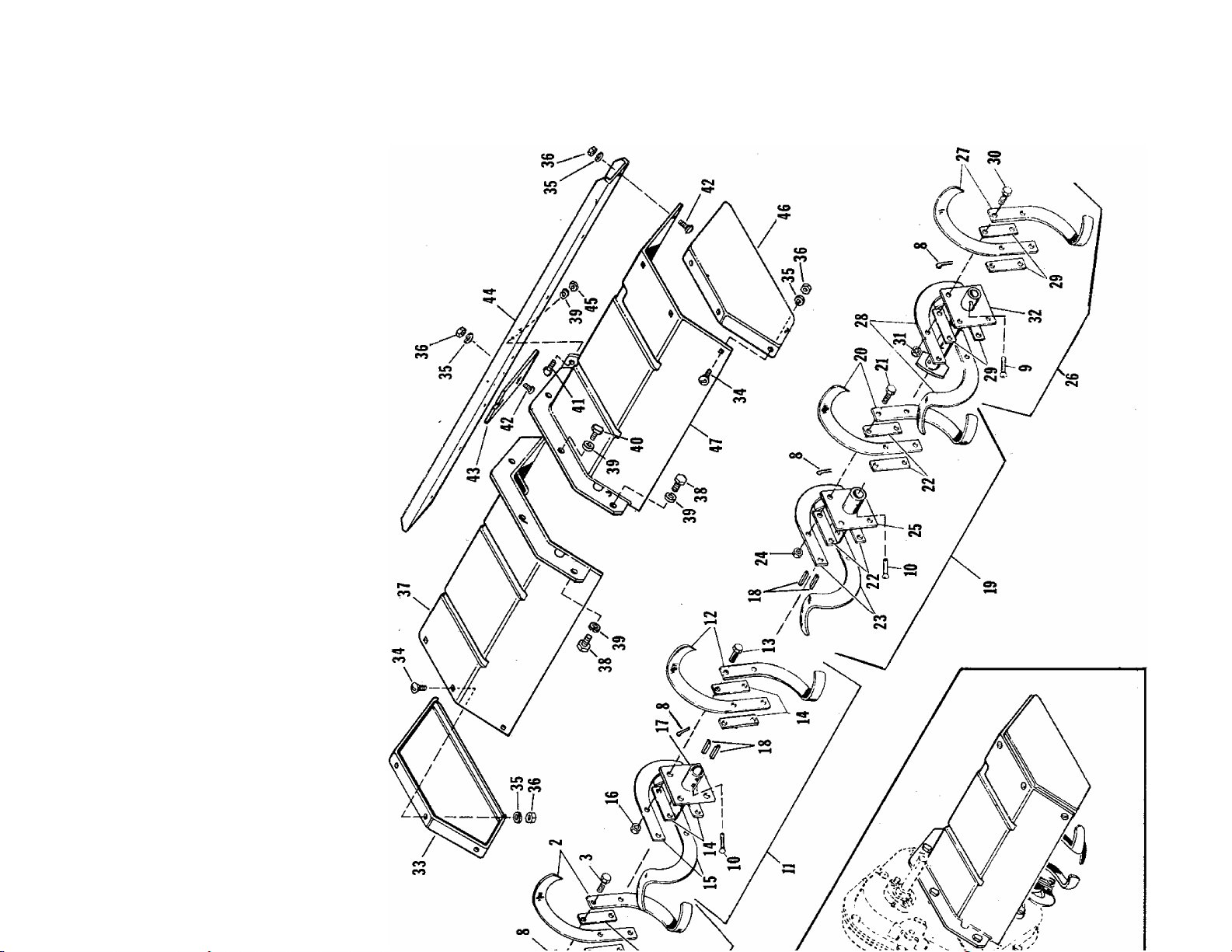
DEFLECTOR & TINE GROUP
Page 7

No.
Description Part No.
Qty.
Kj
1 BIADE ASSEMBLY (R. H,)
Includes:
2
3
TINE-blade (left hand)
SCREW-hex cap, 7/16-20 x 2
4 SPACER
5
6
7
8
9
10
11
TINE BLADE (right hand)
NUT-hexlock, 7/16-20
PLATE-tine
PIN-cotter, 1/8 X 3/4
PIN
PIN-inner
BLADE ASSEMBLY-inner (R. H.)
Includes:
12
TINE-blade (left hand)
13 SCREW-hex cap, 7/16-20 x 2
14
15
16
SPACER
TINE-blade (right hand)
NUT-hex lock, 7/16-20
17 HUB-attachment
18 KEY
BLADE ASSEMBLY-inner (L. H.)
19
Includes:
20 TINE-blade (left hand)
21
22
23
24
25
26
SCREW-hex cap. 7/16-20 x 2
SPACER
TINE-blade (right hand)
NUT-hex lock, 7/16-20
HUB-attachment
BLADE ASSEMBLY (L. H.)
Includes:
27
28
29
30
31
32
33
34
35
TINE-blade (left hand)
TINE-blade (right hand)
SPACER
SCREW-hex cap, 7/16-20 x 2
NUT-hex lock
PLATE-tine
PLATE-end, deflector (right hand)
BOLT-carriage, 5/16-18 x 1/2
WASHER-lock, 5/16
36 NUT-hex, 5/16-18
DEFLECTOR-right hand
37
SCREW-hex cap, 3/8-16 x 1
38
WASHER-lock, 3/8
39
SCREW-hex cap, 3/8-16 x 5/8
40
SCREW-hex cap, 3/8-16 x 7/8
41
BOLT-carriage, 5/16-18 x 3/4
42
SHIELD
43
CHANNEL-reinforced
44
NUT-hex, 3/8-16
45
PLATE-end, deflector (left hand) LM-01052-73
46
DEFLECTOR-left hand
47
DECAL-safety
LM-01053-90 1
LM-01053-75
LM-07150-95 4
LM-01053-77 4
LM-01053-76 2
LM-09148-80 4
LM-01053-84 1
LM-09184-51 4
LM-01180-53 2
LM-01052-49 2
LM-01053-87
LM-01053-75 2
LM-07150-95 4
LM-01053-77 4
LM-01053-76 2
LM-09148-80 4
LM-01053-81
LM-01053-37 4
LM-01053-88 1
LM-01053-75 2
LM-07150-95 4
LM-01053-77 4
LM-01053-76 2
LM-09148-80 4
LM-01053-81
LM-01053-89
LM-01053-75 2
LM-01053-76 2
LM-01053-77 4
LM-07150-95 4
LM-09148-80 4
LM-01053-84
LM-01052-74 1
LM-07030-11
LM-09173-56 15
LM-09173-72 15
LM-01053-69 1
LM-09212-10 5
LM-09169-65 8
LM-07150-24 1
LM-09193-57 2
LM-09194-14
LM-01053-54 1
LM-01053-30 1
LM-09169-50 2
LM-01053-70 1
LM-01030-31 1
2
1
1
1
1
1
8
7
1
ALWAYS FURNISH MODEL AND SERIAL NUMBER WHEN ORDERING PARTS.
Page 8

TILLER DRIVE GROUP
TORQUE TO 75 FT, LBS.
32
B
36 54
28
Page 9

No. Description
Part No.
Qty
1 HANDLE-clutch
2
CLIP-spring
WASHER-flat, 3/8
3
4
SCREW-hex cap, 7/16-14 x 1-1/4
5 SPACER
6 PIN
NUT-hex lock, 7/16-14
7
SPACER
8
9 LEVER-clutch
10 NUT-hex, 3/8-16
11 WASHER-lock, 3/8
NUT-whiz lock, 5/16-18
12
13 SUPPORT-rear belt guard
14 WASHER-flat, 7/16
SCREW-hex cap, 7/16-14 x 3-1/2
15
16 GUARD-belt
BOLT-carriage, 5/16-18 x 1/2
17
18 KEY
19 PULLEY
20 PULLEY
SCREW-hex cap, 3/8-16 x 1-1/4
21
22 WASHER-flat, 5/16
23 PULLEY-idler
24 PULLEY-idler
25 BELT-V
26 KEY
27 PULLEY
WASHER-flat, 1/2
28
29
SPACER
30
SCREW-hex cap, 1/2-13 x 5
LM-01053-03
LM-01067-87
LM-09173-78
LM-09206-77 1
LM-01053-46 2
LM-01180-53
LM-07175-19
LM-01053-39
LM-01052-95 1
LM-09169-50 4
LM-09169-65
LM-09257-63
LM-01053-59
LM-09184-30 ■ 2
LM-07150-93
LM-01053-26
LM-07030-11 2
LM-01574-27 1
LM-01053-02 1
LM-01053-06
■ LM-09174-00 2
LM-09176-42 2
LM-01640-83
LM-01053-80 1
LM-01053-40
LM-80610-81 1
LM-01642-02 1
LM-09184-31 4
LM-01053-86 - 2
LM-07150-97 1
31 SCREW-hex cap, 3/8-16 x 4-1/2 LM-09220-48 1
32 PIN LM-01550-37
33
CLIP-spring
34 FRAME
LM-01067-88 2
LM-16074-26
35 NUT-hex lock, 3/8-16 LM-09234-28
36
NUT-hex lock, 1/2-13
LM-07175-18 1
37 STOP-belt LM-01670-32 1
38
PIN
39 GUARD-belt
40
SCREW-hex cap, 3/8-16 x 7/8
LM-01563-06
LM-01053-51 1
LM-09193-57 1
41 BRACKET-depth limit LM-01726-39
42
CHAIN LM-01070-31
43 CLIP-spring LM-81610-4 5 2
44 CLIP-chain LM-01082-00 1
NUT-hex lock, 5/16-18
45
GUIDE-rod LM-01584-06 1
46
LM-09233-62 1
47 ROD-clutch LM-01053-43 1
48 SPRING LM-81910-45 1
50 SCREW-set, 1/4-20 x 3/8 LM-09038-07
51 BAR-lift LM-16074-25 1
52
IDLER-arm
LM-01053-22
53 STOP-belt LM-16060-14 1
SCREW-hex, 3/8-16 x 1
54
LM-09077-31
55 SCREW-hex, 7/16-14 x 1-1/4 LM-09234-71
56 WASHER-lock, 7/16
LM-09181-99
1
5
3
1
2
1
4
2
1
1
1
1
1
1
2
1
1
3
1
1
1
1
1
1
1
ALWAYS FURNISH MODEL AND SERIAL NUMBER WHEN ORDERING PARTS.
Page 10

TINE EXTENSION GROUP
ALTERNATE METHOD OF ASSEMBLY
FOR MAXIMUM WIDTH.
No. Description Part No.
BLADE ASSEMBLY (L. H.)
Includes:
1
2
3
4
5 PLATE ASSEMBLY-tine ext. LM-01052-21 1
6
7 CLIP-spring LM-S1610-45 2
8 DEFLECTOR-extension(right hand)
9 DEFLECTOR-extension (left hand) LM-01052-76
10
11 WASHER-lock, 5/16 LM-09173-56 10
12
13 TINE-blade (left hand) LM-81520-01 2
14 TINE-blade (right hand) LM-81520-02 2
15 SCREW-hex cap, 7/16-20 x 1-1/4 LM-09204-88 4
16
17
TINE-blade (left hand) LM-81520-01 2
TINE-blade (right hand)
SCREW-hex cap, 7/16-20 x 1-1/4
NUT-hex lock, 7/16-20
PIN LM-01180-53 2
BOLT-carriage, 5/16-18 x 1/2
NUT-hex, 5/16-18
BLADE ASSEMBLY (R. H.)
Includes:
NUT-hex lock, 7/16-20
PLATE ASSEMBLY-tine ext.
LM-01052-22
LM-81520-02 2
LM-09204-88 4
LM-09148-80 4
LM-01052-75 1
LM-09237-00
LM-09173-72 10
LM-01052-23 1
LM-09148-80 4
LM-01052-21 1
Qtj
1
1
10
10
ALWAYS FURNISH MODEL AND SERIAL NUMBER WHEN ORDERING PARTS.
Page 11

Part No.
Description
Qty.
Part No. Description
Qty,
I ^
LM 01030 31 Decal-safety
LM 01051 32 Bolt-(right hand side) 2
LM 01051 92
LM 01051 94 Ring-retaining 4
LM 01051 96 Bearing-roller 4
LM 01052 21 Plate Assembly 2
LM 01052 22
LM 01052 23 Blade Assembly (R. H.)
LM 01052 49
LM 01052 73
LM 01052 74
LM 01052 75 Deflector Ext. (R. H.)
LM 01052 76
LM 01052 91
LM 01052 92 Spacer-intermediate
LM 01052 95 Lever-clutch
LM 01052 97
LM 01052 98
LM 01053 01
LM 01053 02
LM 01053 03
LM 01053 06 Pulley
LM 01053 07 Plate-re inforc ing
LM 01053 09
LM 01053 11
LM 01053 13 Plate Assembly
LM 01053 20
LM 01053 22
LM 01053 26
LM 01053 30
LM 01053 36
LM 01053 37
LM 01053 39
LM 01053 40
LM 01053 43
LM 01053 45
LM 01053 46
LM 01053 51
LM 01053 54
LM 01053 57
LM 01053 59
LM 01053 60
LM 01053 63
LM 01053 65
LM 01053 66
LM 01053 67
LM 01053 69
LM 01053 70
LM 01053 73
LM 01053 75
LM 01053 76 Tine-blade {R.H.)
LM 01053 77
LM 01053 80
LM 01053 81
LM 01053 84
LM 01053 86 Spacer
LM 01053 87
LM 01053 88 Blade Assembly (L. H.)
LM 01053 89 Blade Assembly (L. H.)
LM 01053 90 Blade Assembly (R. H.)
LM 01067 87
LM 01067 88
LM 01070 31
Spacer- inter mediate
Blade Assembly (L. H.)
Pin-inner
Plate-deflector (L. H.)
Plate-deflector (R. H.)
Deflector Ext. (L. H.)
■Sprocket Assembly
Shaft Assembly-tine
Shaft-pulley
Sprocket Assembly
Pulley
Handle-clutch
Bearing
Bearing
Bar-side
Arm Assembly-idler
Guard-belt
Channel Reinforcing
Chain
Key
Spacer
Belt-V, 12 hp.
Rod-clutch
Chain
Spacer
Guard -belt
Shield
Seal
Support-belt guard
Spacer
Grease Cap
Seal
Case-half (R. H.)
Case-half (L. H.)
Deflector- (R. H.)
Deflector Assembly (L. H.)
Gasket
Tine-blade (L. H.)
Spacer
Pulley-idler
Hub-attach assembly
Plate Assembly-tine
Blade Assembly (R. H.)
Clip-spring
Clip-hairpin
Chain
16
1
1
1
1
2
1
1
1
1
1
1
1
1
1
1
1
1
1
2
2
2
2
2
1
1
1
2
4
1
1
1
1
2
1
1
2
1
2
2
2
1
1
1
1
1
8
8
1
2
2
2
1
1
1
1
5
2
1
LM 01082 00 Clip-chain
LM 01180 53
LM 01550 37 Pin-rd.hd.
LM 01563 06
LM 01574 27 Key-parallel
LM 01584 06
LM 01640 83 Pulley-idler
LM 01642 02 Pulley-P. T. O.
LM 01670 32 Stop-belt
LM 01726 39
LM 09150 19
LM 16060 14 Stop-belt
LM 16074 25
LM 16074 26
LM 80610 81
LM 81520 01 Blade-tine (L. H.)
LM 81520 02 Blade-tine {R. H.)
LM 81610 45
LM 81910 22 Collar-set
LM 81910 45 Spring
FASTENING PARTS
LM 07030 11
LM 07050 68
LM 07-060 22 1/2-20 X 1-1/4
LM'-07150 24
LM 07150 91
LM 07150 93
LM 07150 95 7/16-20 X 2
LM 07150 97
LM 07175 18
LM 07175 19
LM 09038 07
LM 09077 31
LM 09148 80
LM 09169 50
LM 09169 51
LM 09169 65
LM 09169 66 Washer-lock, 1/2
LM 09173 56 Washer-lock, 5/16
LM 09173 72
LM 09173 78
LM 09174 00
LM 09176 42
LM 09181 99
LM 09184 30
LM 09184 31
LM 09184 51
LM 09193 18
LM 09193 57
LM 09194 14
LM 09204 88
LM 09206 77
LM 09212 10
LM 09212 21
LM 09233 62 Nut-hex, 5/16-18
LM 09220 48
LM 09234 28
LM 09234 71 7/16-14 x 1-1/4
LM 09237 00
LM 09257 63
LM 09287 31
LM 82810 14
Pin-tine shaft 5
Pin-rd.hd.
Guide Assembly-rod
Bracket Assembly
Fitting-grease 2
Lift Bar Assembly
Frame Assembly
Key
Clip-spring
Bolt-carriage
1/2-13 X 4
3/8-16 X 5/8
3/8-16 X 1-1/2
7/16-14 X 3-1/2
1/2-13 X 5
Nut-hex, 1/2-13
Nut-hex, 7/16-14
1/4-20 X 3/8
3/8-16 X 1
Nut-hex cap
Nut-hex, 3/8-16
Nut-hex, 1/2-13
Washer-lock, 3/8
Nut-hex, 5/16-18
Washer-flat, 3/8
3/8-16 X 1-1/4
Washer-flat, 5/16
Washer-lock, 7/16
Washer-flat, 7/16
Washer-flat, 1/2
Pin-cotter, 1/8 X 3/4
5/16-18 X 5/8
3/8-16 X 7/8
Bolt-5/16-18 X 3/4 7
7/16-20 X 1-1/4
7/16-14 X 1-1/4
3/8-16 X 1 5
5/16-18 X 1-1/2
3/8-16 X 4-1/2
Nut-hex, 3/8-16
Bolt-5/16-18 X 1/2
Nut-5/16-18
Nut-hex, 3/8-16
Washer
1
2
3
1
1
1
1
1
1
1
1
1
1
4
4
4
1
1
10
1
2
1
6
1
16
1
1
2
1
1
24
6
1
12
5
29
29
3
2
2
1
2
6
4
14
1
8
1
2
15
1
1
1
10
2
6
4
n
Page 12

PRINTED IN U. S.A.
HOMELITr
* textronl
PORT CHESTER, NEW YORK, U.S.A. 10573
DIVISION
E1272EZ
 Loading...