


HOMELITE
3H.P.
TILLER
3H.P. TILLER MFG. NO. 1600399
TINE EXTENSION KIT MFG. NO. 1600407
FURROW OPENER MFG. NO. 1600373
OPERIITOR'S
mnnuRi
FORM - 1651763
PRINTED IN U.S.A
748

WARRANTY
We warrant this HOMELITE product to be free from defects in material or workmanship under normal use and
service, except that we make no warranty, express or implied, with respect to tires, engines, generators or voltage
regulators {which usually are warranted by their respective manufacturers) nor with respect to any unit which
after sale by HOME LITE has been altered m any way without HOME LITE'S express consent.Our obligation under
this warranty is limited to replacing, without charge any part which is proven defective within one year {30 days
if the unit IS used for commercial, rental or municipal purposes) from date of purchase, if returned to us. with
transportation charges prepaid, at a HOMELITE branch office or to a dealer whom we have authorized to make
the replacement.
THIS WARRANTY IS IN LIEU OF ALL OTHER WARRANTIES. EXPRESS OR IMPLIED, OF MERCHANT
ABILITY. FITNESS FOR A PARTICULAR PURPOSE. PERFORMANCE OR OTHERWISE AND IN NO EVENT
SHALL HOMELITE BE LIABLE FOR ANY INCIDENTAL. SPECIAL OR CONSEQUENTIAL DAMAGES.
HOIVIELITE
a division ot Teitron Inc.
TINE WARRANTY
HOMELITE warrants rotary tiller tines against breakage for the period not to exceed
the normal life of the roUiry tiller; and will replace broken tines directly to the customer
at no diarge, [¡rovided broken tines are returned prepaid to the nearest HOMELITE
district office.
HOMELITE
a division of Teitron Inc
/ i/ I..’
ACCESSORIES
TINE EXTENSION SET (Mfg. NO. 1600407)
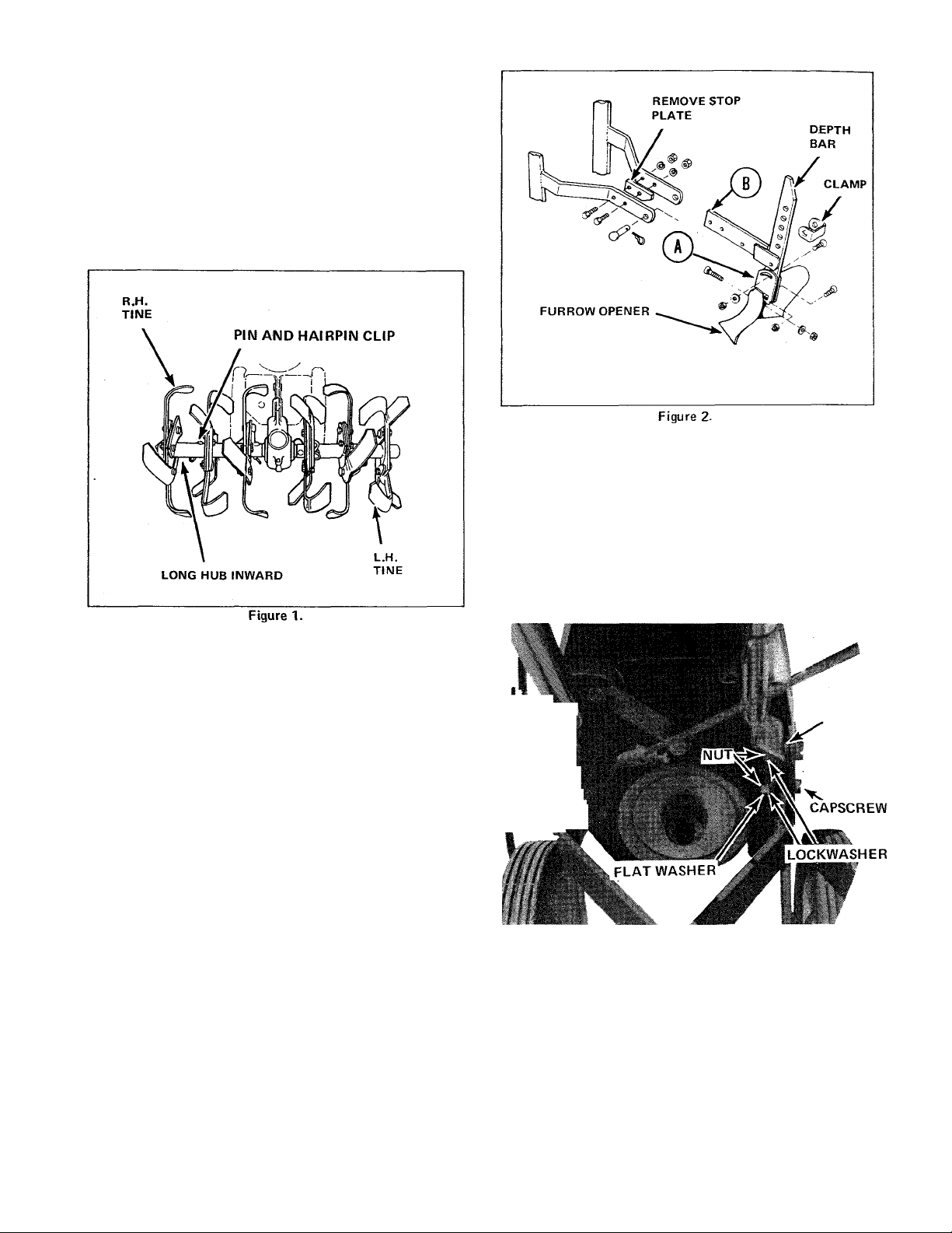
See Figure 1. The extension set consists of a left and right
tine assemblies with mounting pins and hairpin clips. Mount
long hub of extension over outside end of standard tine as
sembly and secure assemblies together with pin and hairpin
clip. Be sure sharpened edges of tines on top face forward.
The extension set increases effective tilling width to 31-1/4-
inches.
ASSEMBLING
1. Remove all components of tiller from box and place
them in a clean, level area. Inspect each part for damage.
FURROW OPENER, 8-INCH (Mfg. No. 1600373)
See Figure 2. The furrow opener is intended for digging
furrows for crops which must be planted in rows. To install,
proceed as follows.
1. Remove the depth bar, turn it upside down and bolt it to
the tool holder (A) with the carriage bolts, washers and nuts
provided.
2. Remove the stop plate from between the frame supports
and install the extension support (B) with the old hardware.
3. Position the depth bar in the extension support and re
install the depth bar clamp using the pin and spring clip pro
vided. Bolt the furrow opener to the tool holder as shown.
SPECIAL WORM GEAR OIL
2. Remove belt cover.
3. See Figure 3. Assemble left and right handles to frame
as shown. Note locations of flat washers.
FLAT
iV
VmLi. m.
Figure 3.
4. Connect throttle cable as follows:
WASHERS (2)
CAPSCREW,
WHIZ-LOCK
CAUTION
Damage to the worm gear drive which results from
use of any lubricant other than that specified will
invalidate the warranty. (See back cover for special
Worm Gear Oil Part Number).
a. Place throttle control lever in SLOW position.

TABLE OF CONTENTS
Page
WARRANTY ........................................................................................................................Inside Cover
SAFETY PRECAUTIONS ............................................................................................................... 1
ACCESSORIES ............................................................................................................................... 2
ASSEMBLING ................................................................................................................................. 2
OPERATION
ADJUSTMENTS .............................................................................................................................. 5
MAINTENANCE .............................................................................................................................. S
OFF-SEASON STORAGE .............................................................................................................. ^
TROUBLESHOOTING .................................................................................................................... 8
SPECIFICATIONS ........................................................................................................................... 9
...................................................................................................................................
4
PARTS LISTINGS
FRAME, HANDLES & WHEELS ....................................................................................................10
ENGINE PULLEY & CONTROL GROUP ......................................................................................11
DRIVE & TINE GROUP .................................................................................................................12
FURROW OPENER .......................................................................................................................13
TINE EXTENSION KIT .................................................................................................................. 13
DECAL LOCATION ........................................................................................................................14
CONGRATULATIONS!
This great new product is engineered with imagination and built with integrity to assure you maximum service and
performance for years to come. To completely understand the operation of your equipment and to take full advantage
of its many fine built-in features, study this instruction manual thoroughly before operating the machine. The little time you
spend reading now will repay you many times over in the time you save and the satisfaction you gain in using your equipment
properly and safely.
SAFETY PRECAUTIONS
Know the controls and how to stop quickly - READ THE
OPERATOR'S MANUAL.
Do not allow children to operate the Tiller. Do not allow
adults to operate it without proper instructions.
Clear the work area of objects which might be picked up and
thrown.
Keep all nuts, bolts and screws tight to be sure equipment is
in safe working condition.
Do not operate equipment when barefoot or wearing open
sandals. Always wear substantial footwear.
Handle gasoline with care - it is highly flammable.
A. Use approved gasoline container.
B. Never remove cap or add gasoline to a running or hot
engine or fill the fuel tank indoors. Wipe up spilled
gasoline.
C. Open doors if the engine is run in a garage. Exhaust
fumes are dangerous. Do not run engine indoors.
Never store equipment with gasoline in the tank inside a
building where fumes may reach an open flame or spark.
Allow the engine to cool before storing in any enclosure.
To reduce fire hazard keep the engine free of grass, leaves or
excessive grease.
Release the clutch lever and stop the engine before cleaning
the tines, removing obstacles, making adjustments, or when
leaving the operating position.
Never allow children or pets to cross your path, or cause dis
tractions in the area while operating.
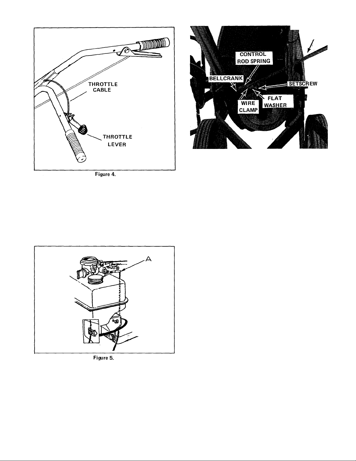
b. Be sure throttle control cable is secured along right
handle with a cable clip.
c. See Figure 5. Route cable under right side of belt
cover, along right side of engine, and up between fuel
tank bracket and starter. Install control wire on throttle
control lever (A).Throttle control lever must be down and
the governor spring relaxed.
d. Loosen clamp screw on fuel tank bracket and install
throttle cable in clamp. Tighten clamp screw.
■ S CONTROL
ROD
Figure 6.
c See Figure 6. Adjust spring tension by loosening
clamp setscrew and moving clamp on control rod. Idler
pulley should be 1/4-inch from frame when clutch dis
engaged (handle released). See Adjustments section of
this manual for clutch adjustment procedure.
d. Secure belt cover to frame with two self-tapping
screws. Tighten two whiz-lock screws attaching part of
handles.
6. Install wheel assemblies as follows;
a. Tilt unit forward on engine.
b. See Figure 7. Secure each wheel assembly (bushing
inward) to frame through lower holes in frame support
with a 3-1/2-inch long capscrew, a lockwasher, and hex
nut. Tighten hex nut.
5. Install forward control rod as follows:
a. See Figure 6. Attach forward control rod springs to
bellcrank.
b. See Figure 6. Slide forward control rod through wire
clamp and inside spring. Loosely secure rod in clamp
with setscrew and flat washer. Hook loose end of spring
between flat washer and clamp.
Figure 7.
7. See Figure 7. Secure depth bar and clamp to rear of
frame with pin and hairpin clip. Digging tip of bar should be
installed as shown.

NOTE: The depth bar setting determines the depth of
tilling. To till 4 to 6 inches deep, install bar mounting pin
in second or third hole from the top. The deeper depth bar
is set into soil, the deeper tines will dig.
8. Loosen each wheel scraper nut and adjust scraper to clear
wheel by 1/8-inch. Tighten scraper nut.
9. Depending upon what tilling width desired, install right
and left tine blade assemblies as follows. Use a pin and
cotter pin for installation. See Figure 8 for right inner,
outer, and extension tine installation.
TILLING WIDTH
INCHES
TINES USED
WARNING
Gasoline is highly inflammable. Avoid overfilling and
wipe up any spilled fuel. Allow no open flame,
smoking, or matches near the area when refueling.
Replace filler cap securely. Store gasoline only in small
quantities. Prolonged storage produces gum and harmful
deposits. If it is necessary to store gasoline for long periods,
add a gasoline stabilizer. See Off-Season Storage section of
this manual.
8-1/2
12
16
** 21-1/2
31-1/4
"denotes moving normal left or right blade assembly to op
posite side. Be sure sharpened'edges face forward.
""denotes standard tine arrangement.
"switched left and right inner
left and right inner
left and right inner
"switched left and right outer
left and right inner
left and right outer
left and right inner
left and right outer
left and right extension
Figure 8.
OPERATION
PREPARING
1. Controls
Figure 9.
c. OIL. See Figure 10. Have available sufficient quan
tities of engine crankcase oil, SAE 30 grade MS. Remove
dirt around engine filler plug. Remove engine filler plug
by turning counter-clockwise. Fill with oil until level
with top of neck. Crankcase capacity is 1-1/4 pints.
Reinstall filler plug securely. Check oil everytime fuel is
added.
See Figure 4. Familiarize yourself with the following
controls:
a. THROTTLE LEVER. Used to adjust engine speed.
b. FORWARD CLUTCH LEVER. Used to control
rotation of tines. Squeeze lever to engage and release
to disengage.
2. Engine
a. MANUALS. Read the engine owner's manual and
this operator's manual thoroughly.
b. FUEL. See Figure 9. Have available sufficient quan
tities of clean, fresh (leaded or non-leaded), "regular"
automotive gasoline. Remove fuel tank cap and fill
tank completely. Fuel capacity is 2 quarts. DO NOT
MIX OIL WITH GASOLINE.
OIL FILLER
PLUG
OIL DRAIN
PLUG
Figure 10.

3. Depth Ваг
See Adjustments section of this manual.
d. A Furrow Opener blade is available for use in digging
furrows for crops which are planted in rows, such as po
tatoes. See Accessories section of this manual.
4. Wheels
See Figure 7. Be sure wheels are mounted in the LOWER
holes of the frame support.
5. Tines
Be sure tines are installed securely with pin and cotter pin.
Sharpened edges must face forward. See Assembly section
of this manual for tine installation.
OPERATION
1. Starting
a. See Figure 4. Move throttle lever halfway between
SLOW and FAST position.
b. See Figure 11. Move stop switch away from spark plug.
c. See Figure 11. Pull choke plunger out to full CFIOKE
position. If engine warm, use half choke.
c. To start engine, grasp starter grip (See Figure 9) firm
ly in right hand and pull sharply straight out. Always
return grip by hand to original position. Do not release
grip with rope extended. When engine starts, push choke
plunger in gradually until it is firmly seated in carburetor
throat.
e. If engine fails to start after four or five pulls, it may
be flooded. Push choke plunger in completely and pull
grip out several times to clear excess fuel.
f. See Figure 11. If engine still fails to start, check fuel
supply and spark plug connections. Be sure engine stop
switch is away from spark plug.
2. Operating
a. When operating the tiller for the first time, proceed
slowly and carefully to get the feel of the unit. Experi
ence will determine pressure and depth bar setting for the
operator.
b. Do not attempt to hold tiller back to cause the tines to
dig deeper. Instead, adjust the depth bar so it will hold
the tiller back. When the tines have dug deep enough in
an area, raise UP slightly on handles and the tiller will
move ahead. To stop the forward motion of the tiller
and cause the tines to raise, put a slight DOWN pressure
on the handles and the depth bar will hold the tiller in
place.
c. Do not till when the soil is very wet. This causes clods,
which are difficult to work up. If the soil is extremely
hard and dry, it may be desirable to cross till an area at
shallow depth first, then till in the direction of planting
rows on the second pass at the final depth.
3. Stopping
a. See Figure 11. Push stop switch against end of spark
plug.
b. If tiller has been operating under full load, allow en
gine to idle for a minute to reduce engine temperature.
Stopping a hot engine suddenly may cause damage to en
gine parts.
STOP ^PLUG
SWITCH
SPARK
CHOKE
PLUNGER
PULL OUT!
TO CHOKE*’
Figure 11.
ADJUSTMENTS
BELT STOPS
Belt stops should be 1/8-inch from belt when clutch engaged
(handle compressed). To adjust, remove belt cover, loosen
stop capscrew, squeeze clutch lever and adjust belt stops as
indicated in Figure 12. Tighten belt stop capscrew and re
place cover.
NOTE: If tines will not stop turning after clutch lever is
released, belt stops may be too far from belt and not braking
belt as required when clutch handle released.
1/8-INCH —
CLEARANCE
ENGINE
PULLEY"
IDLER
PULLEY
DRIVEN
PULLEY
Figure 12.
BELT
STOP
CAPSCREW
1/8-INCH
CLEARNACE
5

CLUTCH
FIRST 5 HOURS OF OPERATION
1. When clutch disengaged (handle released), idler pulley
should be no closer than 1/4-inch from frame and all belt
stops must be firmly gripping the drive belt.
2. When clutch engaged (handle compressed), idler pulley
must press in on belt enough to remove belt from contact
with belt stops. Approximately 1/8-inch clearance between
belt stop and belt should be maintained (See Belt Stop
Adjustment).
3. See Figure 6. If clutch does not operate as described
above in steps 1 and 2, loosen wire clamp setscrew and adjust
wire clamp on control rod to obtain required spring tension.
DEPTH BAR
See Figure 7. The depth bar setting determines the depth
of tilling. To till 4 to 6 inches deep, install the bar moun
ting pin in the second or third hole from the top. Pull out
the hairpin clip to change pin location. Be sure to install
the bar with the digging tip as shown. THE DEEPER
THE DEPTH BAR IS SET INTO THE SOIL, THE DEEP
ER THE TINES WILL DIG.
See Figure 10. Change engine oil as follows:
a. Run engine for a few minutes to warm engine oil.
b. Remove oil drain plug and allow oil to completely
drain from engine.
c. Replace oil drain plug securely.
d. Remove dirt around engine oil filler plug.
e. Remove engine oil filler plug by turning counter
clockwise.
f. Fill with SAE 30 grade MS oil until level with top of
neck. Crankcase capacity is 1-1/4 pints.
g. Reinstall engine oil filler plug securely.
EVERY 5 HOURS OF OPERATION
See Figure 13. Check and add worm drive housing gear oil
as follows:
a. Remove worm gear housing oil filler plug.
CARBURETOR
Minor carburetor adjustments may be required to com
pensate for differences in fuel, temperature, altitude and
load. See your engine owners manual for adjustment pro
cedure.
PULLEY ALIGNMENT
See Figure 12. Visually check alignment of engine, idler,
and driven pulleys. Pulleys must be aligned as closely as
possible or belts will be stretched and worn excessively.
Loosen engine and/or driven pulley setscrews and align
pulleys. Tighten setscrews securely.
MAINTENANCE
Read the engine owner's manual thoroughly.
AFTER EACH USE
Grass, dirt, or chaff may clog engine cylinder head fins and
blower housing. Check for clogged condition and if neces
sary, remove blower housing and clean.
CAUTION
WORM GEAR HOUSING
OIL-FILLER PLUG
Figure 13.
CAUTION
There is a filter in a vent hole located at rear of worm
drive housing. Do not remove this filter for any
reason.
b. Oil level should be level with plug hole when tines
are resting on ground.
c. If oil is required, tip tiller back until handles rest on
ground. Add a small amount of special worm gear oil
through plug hole and slowly lower tiller until tines rest on
ground. Oil should be level with plug hole, if not, repeat
procedure. Do not overfill.
Continued operation with a clogged cooling system
causes severe overheating and possible engine damage.

CAUTION
EVERY 100 HOURS OF OPERATION
DAMAGE TO THE WORM GEAR DRIVE WHICH
RESULTS FROM USE OF ANY LUBRICANT OTH
ER THAN A SPECIAL WORM GEAR OIL WILL
AUTOMATICALLY INVALIDATE THE WARRAN
TY. (See back cover for Special Work Gear Oil Part
Number).
d. Tighten filler plug securely.
NOTE: The worm drive housing may become quite warm
while operating. This is completely normal and no harm
to gears will occur if the housing is kept filled as specified
with the special worm gear oil. .
EVERY 25 HOURS OF OPERATION
1. Change engine oil. Refer to change procedure in FIRST
5 HOURS OF OPERATION.
2. See Figure 14. Clean air cleaner and re-oil element. The
air cleaner normally need not be cleaned for a full season
unless tilling is done under extremely dusty conditions.
Clean every few hours under extremely dusty conditions.
Clean air cleaner as follows:
Clean and reset spark plug gap at 0.030 of an inch. Plug
should be cleaned by scraping or wire brushing and washing
with a commercial solvent or gasoline. Grease the plug
threads before re-installing.
CAUTION
DO NOT BLAST CLEAN PLUG.
LUBRICATION
See Figure 15. To reduce wear and assure free movement
of controls, apply light motor oil occasionally at points in
dicated. Be careful not to get oil on drive belts. Use only
small quantities of oil- Excess oil collects dirt and causes
extra wear. DO NOT OIL SELF-LUBRICATED WHEEL
BEARINGS.
a. Remove screw attaching air cleaner assembly to car
buretor.
b. Remove air cleaner assembly carefully from carburetor
so as to prevent dirt from entering carburetor.
c. Disassemble air cleaner assembly.
d. Wash foam element in kerosene or liquid detergent
and water to remove dirt.
e. Wrap foam in cloth and squeeze dry.
f. Saturate foam in engine oil. Squeeze to remove excess
oil.
g. Assemble parts and secure air cleaner assembly to
carburetor with screwr
To prevent rust, sand off and paint any parts or areas which
become chipped or damaged. Tighten all bolts, capscrews,
nuts, and fasteners securely.
OFF-SEASON STORAGE
If tiller is to be stored over 30 days proceed as follows:
1. Clean fuel screen and bowl. See Maintenance section of
this manual.
2. Drain fuel tank and lines by placing suitable container
under fuel shut-off valve and opening valve. Store gasoline
in container using a gasoline stabilizer or additive. This
additive prevents formation of gum and varnish for up to
one year.
3. Operate engine until gasoline in carburetor is completely
consumed.

4. While engine is still warm, drain oil from crankcase. See
Maintenance section of this manual. Refill with fresh oil.
5. Remove spark plug, pour one ounce (2 or 3 tablespoons)
of SAE 30 oil into cylinder and crank slowly to distribute
oil. Replace spark plug.
6. Clean dirt and chaff from cylinder head fins and blower
housing.
4. See Figure 11. Choke plunger is not pulled out to full
CHOKE position or, if engine appears flooded, pushed
in, to clear excess fuel. To clear a flooded engine, push
choke plunger completely in and pull starter rope several
times.
IF BELT SLIPPAGE OCCURS
1. Belt may be stretched or worn excessively. Replace belt.
TROUBLESHOOTING
IF ENGINE FAILS TO START
1. See Figure 9. Fuel tank may be empty.
2. See Figure 4. Throttle lever is not set halfway between
SLOW and FAST position.
3. Spark plug is not securely connected.
2. Belt may be greasy or oily. If so, use cleaning fluid on a
rag to clean.
3. Pulleys may be misaligned. Refer to Pulley Adjustment
in Adjustments section of this manual.
4. Belt tension may be too loose. Refer to Clutch in
Adjustments section of this manual.

SPECIFICATIONS
ENGINE
TRANSMISSION
TINES
DEPTH
BAR
CONTROLS
CHASSIS
OVERALL
DIMENSIONS
MAKE:
BRIGGS &
STRATTON
STARTER
CHOKE Manual
GOVERNOR
IGNITION
LUBRICATION
FUEL CAPACITY 2 Ouarts
AIR CLEANER Sealed Joint Housing, Reusable Oiled Foam Element
MUFFLER Quiet, Low Back Pressure Type, Side Discharge
TYPE
MATERIAL
BEARINGS
SEALS
LUBRICATION
HOUSING
CLUTCH
TYPE Self-sharpening, non-winding
MATERIAL
TILLING WIDTH 21-1/2 In. Standard, 31-1/4 In. with Tine Extensions
TILLING DEPTH
ATTACHMENTS
DRIVE
SPEED
ATTACHMENT Pin and Hairpin Clip
ADJUSTMENT
LOCATION
FRAME
TIRES
WHEEL BEARINGS
LENGTH
WIDTH
HEIGHT
WEIGHT
■ MODEL NO: 80200 ■ STROKE: 1-3/4 Inches
■ CYCLES: 4 ■ DISPLACEMENT: 7.75 Cu. In.
■ CYLINDERS; 1 ■ CRANKSHAFT
■ BORE: 2-3/8 Inches PLANE: Horizontal
TYPE NO.: 0252-01 _
Manual Rewind, easy spin
Adjustable Mechanical, 1800 - 4000 RPM
Magneto
Gear Impeller System - 40% Slope Operation
CRANKCASE CAPACITY: 1-1/4 Pints
Worm and Gear
WORM: Carburized Steel
GEAR: Bronze
FRONT: Tapered Roller Bearing
REAR: Tapered Roller Bearing
DOUBLE LIP: Dirt Excluding
Special Worm Gear Oil (See back cover).
Cast Iron
Touch-O-Matic V-Belt
Forged, High-Carbon Steel
0 to 7 Inches, Adjustable
TO HUB: Bolted
TO SHAFT: Pin and Cotter Pin
INNER: Pin Type Floating Drive
OUTER: Pin and Torsion Plate Floatinq\Drive
75 RPM at Full Engine Speed
0 to 7 Inches Tilling Depth
FORWARD CLUTCH: Right Handle, Top
THROTTLE: Left Handle
REWIND STARTER AND CHOKE: On Engine
Heavy-Duty, Electrically Welded with Cross-Bracing
8x1.75 Solid Rubber
Solid, Sintered Iron
51 Inches
26 Inches (Without Tine Extensions)
TO TOP OF HANDLE; 38-1/4 Inches
TO TOP OF ENGINE: 27-3/4 Inches
NET (DRY); 113 Lbs.
SHIPPING (DRY): 123 Lbs.
SPECIFICATIONS ARE SUBJECT TO CHANGE WITHOUT NOTICE.

3H.P. TILLER
ENGINE PULLEY & CONTROL GROUP
Ref.
No. Part No. Qty. Description
1
2
3
4
5
6
7
8 118027
9
10
11
12
118464 1
919354
917642
917356
917372
118463 6 SHIM
118470
905850
928691
118312
154534
4 CAPSCREW, Hex, 5/16
8 WASHER, Flat, 5/16
4 LOCKWASHER, 5/16
4
1 PULLEY, Driven
1
1
1
1
1 PULLEY, Idler
ENGINE
18x 2
NUT, Hex, 5/16-18
PULLEY, Engine
KEY, Square
SETSCREW, Cup
BELT, "V"
Ref.
No.
13
14
15 921971 1
16 916965 1 LOCKWASHER, 3/8
17
18 1609352 1
19
20 923362 1 LOCKNUT. Hex, 5/16
21 106545 1
22 118037 1
23
24
Part No.
118335 1
917642 1
916950
171337
909589
921370
Qty. Description
SPACER
WASHER. Flat, 5/16
CAPSCREW. Hex, 3/8-
16 X 1-3/4
1 NUT, Hex, 3/8
LEVER, Idler pulley
1 BOLT, Pivot
STOP, Belt
STOP, Beit
1
1 CAPSCREW, Hex, 1/2-
LOCKWASHER, 1/2
20 X 1
11

3H.P. TILLER
Ref.
No.
1
2
3
4
5
6
7
8 911171
9
10
n
12
13
14
15
16
17
18
19
20
21
22*
22*
23
Worm Drive Assy.
* Selective fit due
Part No.
118400
118393
118396 2
154393
154486
170888 1
118439 1
118399 1
118392
118462 1
901653 1
118492
118398
154487
118021 1
118403
118118
118020
118315
118022
170885
171762
118024
Qty.
1
1
2
2
1
1
1
1
1
2
2
2
2
1
1
1
1
consists of Ref. IMos. 1 through 27.
to machining of components^
Description
SHIELD
SEAL, Oil
RING, Retaining
CUP, Bearing
CONE, Bearing
SHAFT, Worm
KEY
KEY, 3/16x7/8
CUP
HOUSING, Worm drive
PLUG, Vent
PIPE, Plug 3/8
WORM, R.H.
SPACER
CAP, Hub
SHAFT, Worm gear
SHIELD
SEAL, Oil
BEARING, Needle
WASHER, Thrust
GEAR, Worm R.H.
RING, Backing
RING, Backing
GASKET
Ref.
No. Part No.
24 118402
25
26
27
28
29 8152001
30
31 920488 32
32
33
34
35 1609339
36
37
38
39 918451
921959
916964
930246
1609337
8152002
928867 32
1609332 2
1609338
1609334
1609340
118053 4
12
Qty. Description
1
4
4
1
COVER
CAPSCREW, Hex hd., 1/4-
20 N.C. X 5/8
LOCKWASHER, 1/4
1, KEY, Woodruff,474 x
3/4
BLADE ASSY., L.H. Inner,
Tine
8
8
1
1
2
1
BLADE, L.H. Tine
BLADE, R.H. Tine
CAPSCREW, Hex, 7/16,
20 X 1-1/4
NUT, full hex, 7/16-20
PLATE ASSY., inner tine
BLADE ASSEMBLY,
R.H. Inner Tine
BLADE ASSEMBLY, L.H.,
Tine, Outer
PLATE ASSY., Tine,
Extension Outer
BLADE ASSEMBLY, R.H.,
Tine Outer
PIN
PIN, Cotter, 1/8 X 3/4
4

Ref.
No. Part No.
3H.P. TILLER
MFG. NO. 1600373
FURROW OPENER
Qty. Description
1
2
3
4
5
6
7
8
8271503 1 TOOL HOLDER ASSY.
118287 1
103010 1
922109
917378 1
916950
118053 1 PIN
918196
2 BOLT, 3/8-16 X 1-1/4
2 NUT, Hex, 3/8
1
SUPPORT ASSEMBLY
OPENER, Furrow, 8-Inch
WASHER, Flat, 3/8
CLIP, Hairpin
3 H.P. TILLER
MFG. NO. 1600407
TINE EXTENSION KIT
Ref.
No.
Part No. Qty.
Description
1
2
3
4
5
6
7
8
9
1609339 1 BLADE ASSY., Tine left
1609334 2
1609340 1 BLADE ASSY., Tine right
118053
918196 2 CLIP, Hairpin
8152001
8152002
920488
928867
2
4
4
8 CAPSCREW, hex, 7/16-20 x 1-1/4
8 LOCKNUT, hex, 7/16-20
HUB & PLATE ASSY.
PIN
BLADE, Tine, left
BLADE, Tine, right
13


LIMITED WARRANTY
New SIMPLICITY products sold by Simplicity Manufacturing Company are warranted by Allis-Chalmers
Corporation (the Company) to be merchantable and free of defects in workmanship and material at the
time of shipment from the Company’s factory. THERE ARE NO WARRANTIES WHICH EXTEND
BEYOND THOSE EXPRESSLY STATED HEREIN.
No warranty of any kind, statutory, implied or otherwise, is made or shall be imposed upon the Com
pany with respect to (1) new products which have been subject to operation in excess of recommended
capacities, misuse, negligence, or accident, or have been altered or repaired in any manner not authorized
by the Company, or (2) tires, engines, generators, voltage regulators or accessories that are warranted
separately by their respective manufacturers except that the Company agrees to make available to the
first user whatever warranty benefits may be made available to the Company by such manufacturer.
The Company will repair or replace, without charge, any part which under normal use and service fails
to conform to this warranty, provided that such parts shall be returned to the Company’s authorized
Dealer, transportation charges prepaid, within 12 months from the date of delivery of such new
product to the first user.
Parts installed by an authorized Dealer, including parts furnished under this warranty, are warranted to
be free from defects in workmanship and material for a period of 90 days from the date of installation of
such parts or to the expiration of the original warranty, whichever is later. The Company will repair
or replace, without charge, any part not conforming to this warranty.
THE COMPANY’S LIABILITY ARISING OUT OF WARRANTIES, REPRESENTATIONS, INSTRUC
TIONS, OR DEFECTS FROM ANY CAUSE, SHALL BE LIMITED EXCLUSIVELY TO REPAIR OR
REPLACING PARTS UNDER THE CONDITIONS AS AFORESAID, AND IN NO EVENT WILL THE
COMPANY BE LIABLE FOR CONSEQUENTIAL DAMAGES.
Service under the terms of this warranty must be obtained at an authorized Simplicity Dealer.
Rotary tiller tines are warranted against breakage for the normal life of the rotary tiller. Simply return
any broken tine to an authorized Simplicity Dealer, and the broken tine will be replaced at no charge.
 Loading...