

Page 1

HOMELITE
RE-8E
•ip<^-'
® -’ v-'C. .
°'P<¿
py-!,--' «
^t.‘r>
;e.i
4^®
^"- ^4^v, S^~-"
“•/,*>
■* a
RE-8E, 8 H.P., SHUTTLE, ELECTRIC, W/30" MOWER, MFC. NO. 1690059
TRACTOR, 8 H.P., SHUTTLE MFC. NO. 1690058
Rotary Mower, 30-Inch, Mfg. No. 1651030
Grass Catcher, Rear Mounted, Mfg. No. 1600383
Counterweight, Mfg. No. 1600351
®-í?a»
’4'-
•fi'}’ •• 's'
at*,,.».«?» “
il'C-'"'' «
'y.r Ji.'J ' fl I'-'-
'A ^ 0^ s*
'^.•'«‘4^.- 8.'V
O f.ifl .1 .
W’»»' . ^ . Í
f,. S. *
,v f . •»
* •=“
■’i- ‘
Hv^’f 5 ^
-^¿>»•««1°«*®..®-«^' ¡I ..*»
»J* « 'is- » b'a«.í» "■ -
n‘<a^ ^ N
’.,®3
af=a9 — ;■ a'a'®'» «■.•'»••,;•.
‘=6‘*'=*i Ac'' ®
-I ^
FORM - 1651660
PRINTED IN U.S.A.
749
Page 2

SAFETY PRECAUTIONS TO PROTECT YOURSELF AND OTHERS
IMPORTANT
OPERATION
Know the controls and how to stop quickly. READ THE
OPERATOR'S MANUAL.
Do not allow children to operate vehicle. Do not allow adults
to operate it without proper instruction.
Do not carry passengers. KEEP CHILDREN AND PETS A
SAFE DISTANCE AWAY.
Clear work area of objects which might be picked up and
thrown.
Take all possible precautions when leaving vehicle unat
tended; such as disengaging power-take-off, lowering attach
ments, shifting into neutral, setting parking brake, stopping
engine and removing key.
Do not stop or start suddenly when going uphill or down
hill. Mow up and down the face of steep slopes; never across
the face.
Reduce speed on slopes and in sharp turns to prevent tipping
or loss of control. Exercise extreme caution when changing
direction on slopes.
Stay alert for holes in terrain and other hidden hazards.
Use care when pulling loads or using heavy equipment.
A. Use only approved drawbar hitch points.
B. Limit loads to those you can safely control.
C. Do not turn sharply. Use care when backing.
D. Use counterweight (s) or wheel weights when sug
gested in operator's manual.
Watch for traffic when crossing or near roadways.
Keep all nuts, bolts, and screws tight to be sure equipment
is in safe working condition.
Do not change engine governor settings or overspeed engine.
Do not operate equipment when barefoot or wearing open
sandals. Always wear substantial footwear.
FUEL AND FIRE HAZARDS
Handle gasoline with care - it is highly flammable.
A. Use approved gasoline container.
B. Never remove cap or add gasoline to a running or hot
engine or fill fuel tank indoors. Wipe up spilled gaso
line.
C. Open doors if engine is run in garage - exhaust fumes
aré dangerous. Do not run engine indoors.
Never store equipment with gasoline in the tank inside a
building where fumes may reach an open flame or spark.
Allow engine to cool before storing in any enclosure.
To reduce fire hazard keep engine free of grass, leaves or
excessive grease.
ATTACHMENTS
Disengage power to attachments and stop engine before
leaving operator position.
Disengage power to attachment (s) and stop engine before
making any repairs or adjustments.
Disengage power to attachments when transporting or not
in use.
When using any attachments never direct discharge of ma
terial toward bystanders or allow anyone near vehicle while
in operation.
Keep vehicle and attachments in good operating condition
and keep safety devices in place. Use guards as instructed in
operator's manual.
Vehicle and attachments should be stopped and inspected
for damage after striking a foreign object and the damage
should be repaired before restarting and operating the equip
ment.
When using vehicle with mower:
(1) Mow only in daylight or in good artificial light.
(2) Never make a cutting height adjustment while en
gine is running if operator must dismount to do so.
(3) Shut engine off when removing grass catcher and/or
unclogging chutes.
(4) Check blade mounting bolts for proper tightness at
frequent intervals.
Check grass catcher bags frequently for wear or deterioration.
Replace with new bags for safety protection.
Page 3

TABLE OF CONTENTS
Райе
SAFETY PRECAUTIONS ..........................................................................................Inside Cover
WARRANTY ..........................
ASSEMBLING ................................................................................................................................. 2
ACCESSORIES .................................................................................................................................. 2
OPERATION ....................................................................................................................................... 4
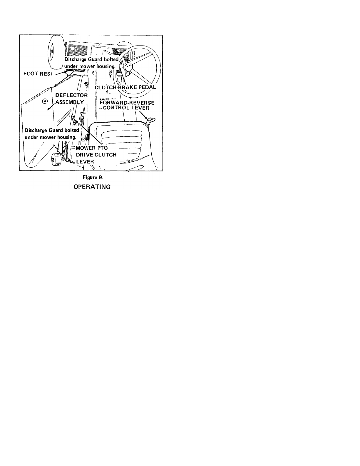
OPERATING ...................................................................................................................................... 6
ADJUSTMENTS
maintenance ....................................
OFF SEASON STORAGE
TROUBLESHOOTING ...................................................................................................................... 16
SPECIFICATIONS ....
PARTS LISTINGS
FRONT & REAR^TIRES ..............................................................................................................18
POWER TAKE OFF
FRONT FRAME & STEERING .................................................................................................. 20
TRANSMISSION & REAR AXLE _____________...........
CLUTCH & BRAKE
REAR FRAME SEAT &ENGINE
FILM & DECALS
ELECTRICAL STARTER ............................................................................................................ 28
; MOVVER HOUSING
MOWER CONTROL ................................................................................................................. 32
REAR MOUNTED GRASS CATCHER ........................................................................................34
.......................
..........
■■■■■••
........................................ . .
..
. .
...
.....................................................................................11
............
....................................................................................................15
.......
.....................................
...........
......................................................................................................... 19
...........
..................................... . . . . . . . . . .
.............
..........
........................................................................................ . .
.............
..........................................
......................................................................
.......................................................
. . ^ . . . .
................................................................................. 26
.......
..........................................
....
V . . . \ . . ............................ 30
..................................
.....................................
...
.............
1
7
\l
.22
24
27
WARRANTY
We warrant this HOMELITE product to be free from defects in material or workmanship under normal use and
service, except that we make no warranty, express or implied, with respect to tires, engines, generators or voltage
regulators (which usually are warranted by their respective manufacturers) nor.wjth respect to any unit which
after sale by HOMELITE hasbeen-altered in any way without HQMELITE'S express consent.Our obligation under
this warranty is limited to replacing, without charge any part which is proven defective within one year (30 days
if the unit is used for commercial, rental or municipal purposes) from date of purchase, if returned to us, with
transportation charges prepaid, at a HOMELITE branch office or to a dealer whom we have authorized to make
the replacement,
THIS WARRANTY IS IN LIEU OF ALL OTHER WARRANTIES, EXPRESS OR IMPLIED, OF MERCHANT
ABILITY, FITNESS FOR A PARTICULAR PURPOSE, PERFORMANCE OR OTHERWISE AND IN NO EVENT
SHALL HOMELITE BE LIABLE FOR ANY INCIDENTAL, SPECIAL OR CONSEQUENTIAL DAMAGES.
HOMELITE
a division of Textron Inc.
Page 4
ASSEMBLING
The riding mower is shipped with mower attached to tractor.
Remove all shipping materials. The following preparation
is required:
REAR MOUNTED GRASS CATCHER
1. Place steering wheel on steering shaft and secure with
bolt and nut
NOTE
If rear mounted grass catcher is to be used with riding
mower avoid step number two (below). Deflector will
not be used with adapter.
2. Secure mower deflector to mower housing with bolts,
flat washers, lockwashers and nuts.
3. Using mower lift lever, raise mower.
4. Remove battery from mounting bracket. Fill each cell
with standard battery electrolyte to the level marks shown
on case. Charge' battery until specific gravity of electrolyte
is 1.260.
CAUTION
Use only a 12 volt charger at less than 1.5 ampere
charging rate. Any higher charging rate will damage
battery.
Place battery back on the mounting bracket with the ter
minals toward the center of tractor and secure in place
with rubber clamp.
If a rear mounted grass catcher is used, assemble and attach
it to vehicle as follows:
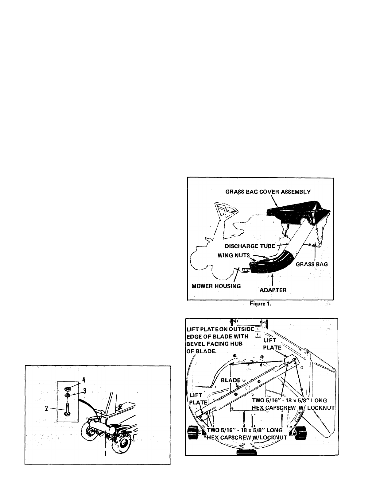
1. See Figure 1. Remove two 3/4-inch long carriage bolts,
flat washers, lockwashers, and nuts attaching deflector to
housing. Remove deflector from housing. Secure adapter
to housing with two 1-inch long carriage bolts (installed
from inside of adapter) and wing nut assemblies. Be sure
to replace discharge deflector, using wing nuts, whenever
adapter is removed.
2. See Figure 2. Attach mower lift plates (bevel to inside
of housing) to mower blade with four capscrews and
locknuts.
ACCESSORIES
COUNTERWEIGHT
t. A: fronts cpu.rrterweighti, is recommended when using a
rear mounted grass catcher oh siopes of 15-30%. Mowing
slopes greater than 30% is not recommended.
2. See Figure A. Attach Counterweight assembly (1) with
two carriage bolts (2), lockwashers (3), and hex nuts (4).
Holes for weight are stamped in frame and are located under
rubber foot pads. After weight is installed, replace rubber
foot pads over the counterweight assembly.
Figure A
Figure 2.
Page 5
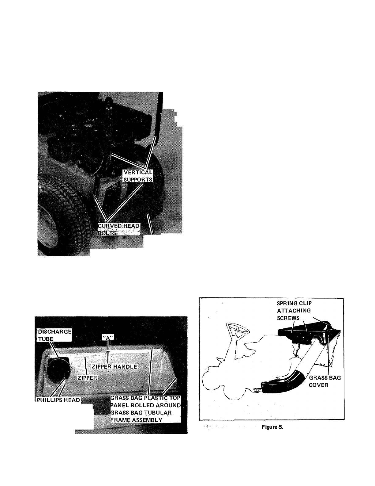
3. See Figure 3. Attach two vertical supports to rear of unit.
Holes are pre-starriped in tractor, frairie. Use two curved
head bolts, lockwashers, and nuts to fasten each vertical sup
port to unit.
5. See Figure 3. The grass bag tubular frame assembly, on
which the grass bag hangs, has two tubular supports welded
to its front side in position to fit over vertical supports. To
install bag on this frame, bag zipper must be completely
unzipped, allowing grass bag plastic top panel to unfold.
m
U
1
REAR GOVER
(OPEN)
Figure 3.
^^;iSe&9F.igure 4.- .^©'jEMschá^^^ is shipped as a flat
.plastic sheet. Roll it i%o a tube and hold in shape with
phillips-htead screws. InStaiFscrews from;inside with a flat
washer under head of screw. ; Place another fiat Washer bn
outside^of -tube followed.by a.lockwasher arid nut: install
discharge tube-on end of;, chapter as shown in Figure 1.
6. On front side of grass bag, opposite mesh panel, there
are two holes in plastic top panel. Insert two tubular sup
ports welded to grass bag frame down through these two
holes with cloth portion of bag toward inside of frame and
with plastic top panel on outside of frame.
7. Roll plastic top panel up and over frame tube and bring
two halves of zipper together on inside of frame. Connect
ends of zipper together at point "A". See Figure 4. Work
zipper handle counter-clockwise completely around frame.
8. See Figure 3. Install frame and bag assémbly in vertical
supports. Insert rear end of discharge tube in hole at left
front corner of grass bag. See Figure 4.
9. See Figure 5. To install grass bag cover, position it above
bag, align cutout on front side with discharge tube, and push
down firmly to snap spring clips over outside of bag frame,
and top panel.
WARNING
Before emptying grass bag, always stop tractor, dis
engage power take-off drive to mower, place trans
mission in neutral, apply parking brake, and stop
engine.
SCREWS
GRASSBAG '
MESH PANEL
Figure 4.
Page 6
10. To empty grass bag, pull up on cover to unsnap spring
clips and remove cover. Lift bag and frame straight up until
frame tubular supports come off of vertical supports. Turn
bag and frame over to dump grass clippings. Replace bag
tubular supports over vertical supports and lower in place,
slipping bag over discharge tube. Place grass bag cover over
bag frame and snap clips in place over bag frame.
NOTE: One front counterweight is recommended when
using grass catcher on slopes 15-30 percent. Mowing slopes
greater than 30% is not recommended.
c. Gear Shift Lever
See Figure 6. Pulling up on gear shift lever places the trans
mission in low range. Pushing dovvn engages the high range
gearing. Shift lever must be placed in neutral midway be
tween high and low range to engage a safety interlock switch
to permit starting the engine (Figure 7|. To shift gears with
engine running, either the clutch-brake pedal must be fully
depressed, or the foryvard reverse contrbi lever must be
placed in neutral.
d. Forward-Reverse Control Lever
OPERATION
PREPARING
Controls
Before attempting to use the riding mower, acquaint your
self with all of the controls and how they operate.
STEERING
WHEEL
FORWARD-REVERSE i
CONTROL LEVER
GEAR ,
SHIFT
LEVER
MOWER HEIGHT
CONTROL CRANK
IGNITION
SWITCH &
KEY
CLUTCHBRAKE
PEDAL
See Figure 6. The forward-reverse control lever operates
the transmission shuttle clutch and perrriits starting and
stopping the tractor in either forward or reverse direction
without shifting gears or using the fbot clutch. The shuttle
clutch may be used for a short time to "inch" the tractor
forward or backward, and to start and stop motion smoothly.
IT MUST NOT be used as a speed change device. All con
tinuous operation MUST be done in either fully forward or
fully rearward position.
Figure 6.
a. Clutch Brake Pedal
See Figure 6. Pushing the clutch-brake pedal forward first,
loosens and disengages the transmission drive belts. Further
forward motion of the pedal applies the brakes.
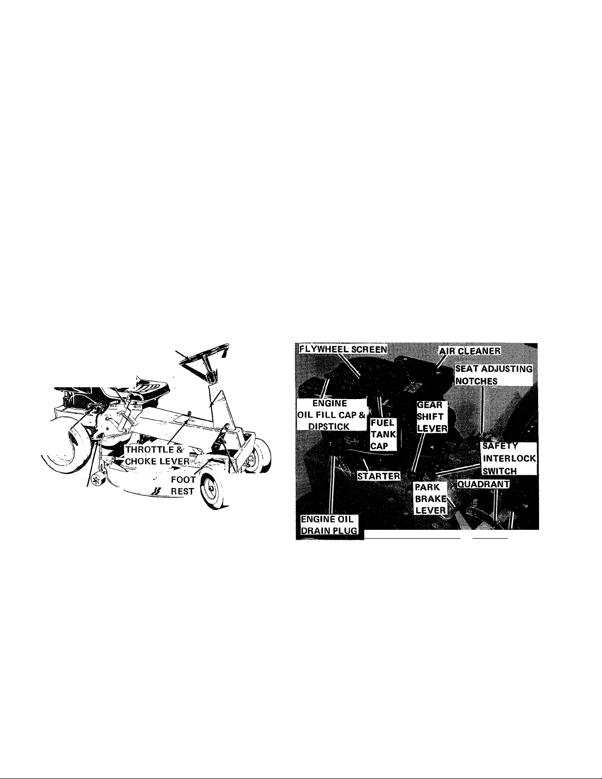
b. Throttle and Choke Levet '’
See Figure 6. The throttle and choke lever controls the en
gine speed from idle to full speed. Moving the lever farther
forward past the "fast" position applies the choke for
starting the engine. As soon as engine starts the lever should
be pulled back to mid-range and engine allowed to warm up
a few minutes before applying a load. When operating at
full throttle be careful that the lever is not moved so far
forward that the choke is partially closed.
IFORWARD REVERSE CONTROL LEVER
Figure 7.
To operate in forward direction, select high or low gear
shift range. With engine running and clutch-brake pedal
fully up in engaged position, move forward-reverse control
lever smoothly, but firmly, forward and engage it in for
ward notch in quadrant. To stop, disengage lever from
forward notch and pull it smoothly, but firmly, to rear
arid place in neutral notch.
To operate in reverse for any appreciable distance, pull the
lever frorn neutral to the rear and of quadrant and hold
ifthere until you wish to stop rearward travel; at which time
it should be pushed forward to neutral notch. When oper
ating in reverse, the control lever will automatically be re
turned to neutral when clutch-brake pedal is depressed.
Page 7
e. Ignition Switch
ENGINE
See Figure 6. The ignition switch must be turned to the
"Start" position to actuate the starter. As soon as engine
starts; let go of key and it will automatically return to
"On". Turn key to "Off" to stop the engine,
f. Parking Brake Lever
See Figure 7. The parking brake lever, located under the
right side of the seat, is pushed down to engage brake. Brake
should be engaged when leaving the tractor unattended.
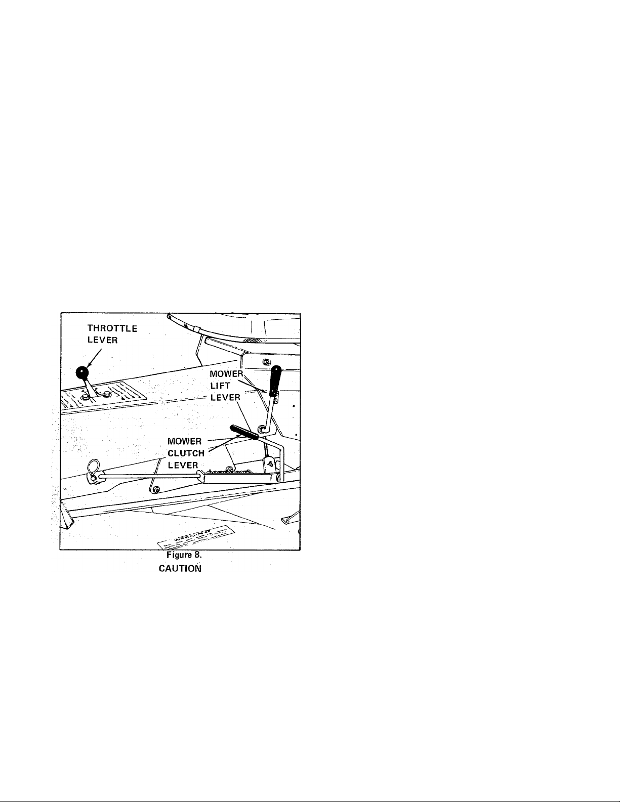
g. Mower P.T.O. Drive Clutch Lever
See Figure 8. The mower PTO drive is engaged by pushing
the mower drive clutch lever forward and down and is dis
engaged by pulling lever upward and back. A safety inter
lock switch requires that lever be in the disengaged position
to start engine.
CAUTION
Study the Safety Rules in this manual and follow all
of them when operating this riding mower.
a. Read the engine owner's manual thoroughly.
b. Check engine oil level, (Figure 7), and add oil as re
quired to maintain level up to full mark on dipstick.
NOTE: Use only a high quality detergent oil classified as
"SC", or "SD" or "MS". For summer operation, use SAE
30. If under 40 degrees, use .10W-30.
c. Fill the fuel tank (Figure 7) with a good grade of regular
gasoline. DO NOT use premium gasoline and DO NOT
mix oil with gasoline.
CAUTION
Gasoline is highly flammable. Avoid overfilling and
wipe up any spilled fuel. Allow no open flame,
smoking or matches near the area of refueling.
MOWER
Never leave the operators seat without disengaging
mower drive.
h. Mower Height Control Crank
See Figure 6. The cutting height of the; mower can be ad
justed from 1-1/2 to 3-1/2 inches by rotating the height con
trol crank. Turn clockwise to raise and counter-clockwise
to lower.
i. Mower Lift Lever
a. Be sure that you are familiar with the safety precautions,
controls and operating instructions given in this manual.
b. Check the mower carefully to be sure that it is properly
installed, leveled, and adjusted - (See Adjustments).
CAUTION
NEVER OPERATE THE MOWER unless the deflector
asserribly and discharge guard are securely bolted in
place, (See Figure 9).
c. Check the condition of mower blade. Keep it sharp and
in balance.
d. Clear the lawn of all sticks, stones, wire and other debris
which may be caught or thrown by the mower blade.
e. Determine the best method of mowing according to the
dimensions, terrain and obstructions of the lawn.
See Figure 8. Pull back to raise mower and push forward
and down to lower mower.
Page 8
STARTING (Figures 6, 7 and 8)
1. Place gear shift lever midway between "Hi" and "Lo".
Place forward-reverse control lever in the neutral notch in
quadrant and raise the mower PTO drive clutch lever to the
disengaged position to actuate the safety interlock switches.
2. Lock the parking brake.
3. Move the throttle lever forward into the "Choke" po
sition.
4. Turn the ignition switch to the "Start" position to
actuate starter. As soon as engine starts, let go of key and
pull throttle lever back to middle of its running range.
Allow engine to warm up. a few minutes before putting it
under load.
5. If the starter will not operate, turn ignition key to off
and check that both the gear shift lever and mower PTO
drive clutch are in neutral position and are actually actuating
the safety interlock switches (Figures 7 and 8).
6. If engine fails to start after being turned over 5 or 10
seconds with the safety interlock switches closed, the engine
may be flooded. If this is the case, pull throttle back to
middle of the range to disengage choke and turn engine
over several times to clear out excess fuel.
TRAVEL
1. With engine running, set engine throttle between 1/4 ano
1/2 open. Engine speed for mowing should be 3/4 to full
throttle. When grass is wet or oyer 3-inches high, full throttle
is best.
2. With forward-reverse lever in the neutral notch, move
the gear shift lever into "Lo" or "Hi" range. Transmission
gear could be placed in "Lo" range when mowing heavy or
Wet grass and when on rough or sloping terrain. Use "Hi"
range on dry, moderate sized grass on smooth terrain.' It is
necessary to place forward-reverse control lever in neutral
or depress the clutch brake pedal to stop tractor before
shifting gears.
NOTE; If there is any tendency for gear teeth to "clash"
when shifting, depress the clutch brake pedal fully. Release
clutch brake pedal slowly and remove foot from pedal.
CAUTION
When operating the tractor for first time put trans
mission in "Lo" gear until you become acquainted
with the controls and operation of the tractor.
3. Grasp steering wheel, straighten front wheels, and look
carefully around to make sure that the area in which you
plan to drive is clear of obstructions, people and pets.
4. Refer to "Forward-Reverse Control Lever" explanation
in the "Controls" section of this manual and engage forward
reverse control lever to start ground travel as instructed.
5. The forward-reverse control lever is not a speed control
device and for ail continuous operation it must be positioned
either fully forward or fully rearward. Practice starting,
stopping, steering, shifting gears, faster throttle settings,
operating in reverse, etc. until you can operate the riding
mower smoothly and easily.
STOPPING
1. Ground travel is normally stopped by placing the forward
reverse control lever in neutral position and moving gear
shift lever to neutral. This action will only stop forward or
reverse drive, it will not brake the vehicle to a stopped
position.
2. Ground travel can also be stopped quickly by fully de
pressing the clutch brake pedal. When forward-reverse con
trol lever is in reverse, depressing clutch brake pedal auto
matically overrides any position the shuttle control lever
would be in. When pedal is released vehicle will assume
operation in the position of the shuttle control lever.
NOTE: Do not keep foot on clutch brake pedal during
operation. To do so can result in "clutch riding" and ex
cessive slippage and wear on drive belts. Place foot on foot
rest.
3. To stop engine, turn the ignition key to the "Off" po
sition and remove key from ignition switch.
Before stopping engine that has been operating under load
allow engine to idle for a few minutes "cooling off" time.
Page 9

CAUTION
Never leave the tractor seat unless the power take off
is disengaged, transmission is in neutral and engine is
stopped. If leaving the tractor unattended, ALWAYS
remove ignition key.
MOWING PATTERN
1. For the first use of the mower choose a smooth level
area. Cut long straight strips overlapping slightly. After
becoming familiar with the operation proceed to inclined
or rougher ground.
2. The size and type of area to be mowed determines the
best mowing pattern to use. Obstructions such as trees,
fences and buildings must also be considered. In most cases,
making one or two passes in a counter-clockwise direction
around the outside of the area to be mowed is advisable to
keep cut grass off of fences, walks, etc. The remainder of
the mowing should normally be done in a clockwise di
rection so the clippings are dispersed on the cut area.
3. Always keep the right side of mower toward trees, posts,
or other obstacles on the first pass around obstacle.
CAUTION
4. On moderate size, frequently mowed lawns where grass
is light and dry it is sometimes practical to mow in a counter
clockwise direction so that clippings are thrown toward the
center of the lawn and concentrated for easy pickup and
removal.
5. Most lawns should be mowed to keep the grass approxi
mately two to three inches high. Best results are obtained
by cutting often and not too short. To keep a green lawn,
never mow more than one third off the height of the grass or
a maximum of one inch in one mowing. For extremely tall
grass, set the cutting height at maximum for first mowing,
then reset to the desired height and mow again. Allow the
grass to grow to three inches, then cut off only the top inch.
6. On thick or springy grass or soft ground, the mower rol
lers may sink into the ground giving too low a cut. Adjust
the cutting height to get the desired height of cut.
7. For best appearance, grass should be cut in the after
noon or evening when it is free of moisture.
8. Where possible change patterns occasionally to eliminate
matting, graining and a corrugated appearance. See diagrams
below.
DO NOT WORK around mower housing area until
you are certain that the mower blade has stopped
rotating.
Heed the CAUTION DECAL, the DANGER DECAL,
and the WARNING DECAL located on the mower
housing. Make certain the discharge guard and de
flector assembly are always in place before operating
mower.
ALWAYS disconnect the mower drive clutch and
stop engine before leaving the tractor seat. If leaving
the tractor and mower unattended, remove the ig
nition key.
Page 10
ADJUSTMENTS
IF VEHICLE IS PLACED ON END FOR OVER A
2 HOUR PERIOD, THE BATTERY MUST BE RE
MOVED AND THE FUEL TANK DRAINED.
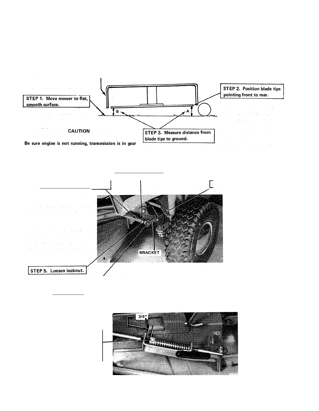
MOWER BLADE FRONT-TO-REAR PITCH
FRONT OF MOWER HOUSING
and mower drive is disengaged (clutch lever up). Block
the wheels, front and rear, to prevent rolling while
working on mower blade.
STEP 7. Tighten locknut.
STEP 6. Adjust turnbuckle until
blade is at desired setting
STEP 4. If distance "A" is not 1/8
to 1/4 inch greater than distance "B
remove eyebolt.
MOWER ENGAGEMENT
STEP 8. Secure eyebolt.
_________________
With clutch lever
engaged (lever down).
Loosen collar setscrew
and adjust to 3/4 inch
if necessary.
Page 11
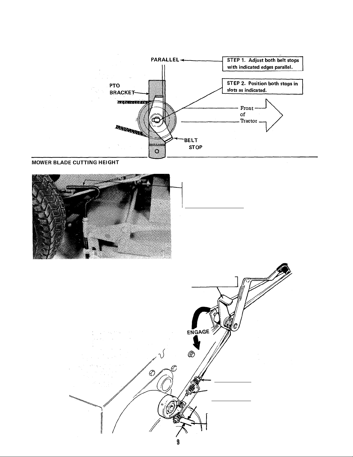
WIOWER BELT STOPS
Raise or lower entire
mower by turning
handle clockwise to raise
counter-clockwise to lower.
BRAKE MECHANISM
NOTE
Brake by either depressing clutch
pedal or engaging park brake lever.
When clutch pedal is depressed,
clutching and braking are at the
same time.
Suggested Cutting Height 2 inches.
STEP 2- Engage parking brake lever.
STEP 1. Turn nut to end of
threaded portion.
STEP 3. Tighten nut until spring is
compressed solid.
NOTE
__________
____________
STEP 4. Adjust nut to 1 to 1-1/4 inch
between washer and bracket.
Page 12

TRACTOR DRIVE MECHANISM
IDLE
BRACKET
SPRING
CAPSCREW
FLAT
WASHER
STEP 1. Place direction control
lever in "Neutral" position.
STEP 2. Open tractor rear cover.
STEP 3. Adjust nut until spring
is compressed 1-1/8 inches.
STEP 4. Turn elastic nut
snug against frame.
STEP 5. Close cover, place
tractor in upright position.
STEPS. Place reference mark.'
STEP 10. Place reference mark and
check indicated dimension.
STEP 7. Rotate shaft awgy from
you as far as possible.
STEP 9. Rotate shaft toward
you as far as possible.
STEP 12. Adjust shaft assembly by
raising or lowering to obtain indicated
dimension (Step 10).
_______________
STEP 11. If indicated dimension not
obtained, loosen four capscrews.
STEP 13. Secure capscrews to 15
foot-pounds torque.
10
Page 13

. BATTERY
*“ RUBBER
MOWER REMOVAL AND INSTALLATION
(Figure 16)
Remove mower as follows:
1. Lower mower to ground and remove lift link from raise
and lower lever.
2. Pull lock pin holding front of mower PTO drive clutch
rod to tractor and lay clutch rod on top of mower. Swing
PTO clutch lever forward for clearance.
3. Remove pins and lock pins holding mower link assembly
to axle attaching clips. Lower front of mower to ground.
.4. Raise rear end of belt cover and remove mower drive
belt from mower driven pulley.
Figure 15.
The maximum charge rate of this battery is 1.5 amps.
Any higher charging rate will damage battery.
AXLE ATTACHING
CLIP
MOWER INSPECTION
After each mowing clean the grass clippings and matérial
from the mower housing and inspect the blade for sharpness
and straightness.
Be sure that tractor engine is stopped, ignition key is
turned to “Off" and removed from switch, gear shift
lever is in neutral, forward-reverse control lever is in
neutral, mower drive clutch is disengaged and that
mower knife has stopped turning before attempting
to inspect or clean mower housing. .
if blade is bent, damaged or dull, the mower will have to be
removed from the tractor.
CAUTION
MOWER PTO DRIVE
CLUTCH LEVER
Figure 16.
WARNING
WARNING
5. Lift front end of tractor and push tractor backwards
until front wheels can be set on the ground back of mower.
. Install the mower as follows;
1. Position mower on ground with rear of mower in front
of tractor front wheels. Pick up front of tractor and pull
tractor forward on its rear wheels until front wheels can
be set down- on ground in front of mower.
2. Lift rear end of belt cover and install mower drive belt
over mower driven pulley. Lower belt cover to hold belt in
place.
3. Lift front end of mower and attach link assembly to
axle attaching clips with pins and lock pins.
4. Attach front end of mower PTO drive clutch rod to clutch
arm on trgctor yyith lock pin. Engage clutch and check that
belt is properly seated in the pulleys.
5. Attach lift link to. raise and lower lever and raise mower.
DO NOT try to remove or sharpen blade with mower
attached to tractor.
13
Page 14

BLADE REPLACEMENT
1. Remove the mower from tractor as outlined on preceding
pages and turn mower upside down.
2. Wedge a block of wood securely between the end of
blade and the mower housing to prevent blade turning
while loosening and tightening bolts. Remove the two
blade mounting bolts and the blade.
WARNING
ALWAYS handle blade with extreme care to avoid
injury.
3. If blade is bent, do not try to straighten it for reuse. Re
place it with a new blade.
4. If blade is straight and has nolarge nicks, you can sharpen
it yourself. Clamp blade securely in a vise and use a large
mill file along the original bevel. File to a sharp edge.
5. Place a small rod through the center hole of blade and
check for balance. File more metal off of heavy side until
blade does balance.
6. See Figure 17. Carefully clean blade and part of arbor
that blade fastens to. Install new or sharpened blade with
the lift tabs on blade end turned toward top of mower
housing. The blade mounting bolts should be tightened
to 30- foot -pounds of torque;
MOWER
iDLER PULLEY
FORWARD CONTROL
IDLER PULLEY
FORWARD IDLER
BELT
TRANSMISSION
DRIVE BELT
FORWARD
TRANSMISSION
IDLER PULLEY
REVERSE TRANSMISSION
IDLER PULLEY
MOWER DRIVE BELT
(ONE BELT)
UREVERSE CONTROL
IDLER PULLEY
REVERSE
IDLER BELT
TRANSMISSION
DRIVE PULLEY
MOWER DRIVE
PULLEY
ENGINE DRIVE
PULLEY
ENGINE IDLER
PULLEY
Figure 18.
BELT
STOP
7. Rotate blade slowly by hand to see that it clears the
housing all around and that the blade tips are running
in a true plane. If the tips of the blades move up and down
in relation to the mower housing as blade is turned, or if
blades are hard to rotate, the arbor shaft or housing may
be bent.
MOWER DRIVE BELT REPLACEMENT
NOTE: Refer to Figure 18 for location of pulleys and belts.
1. Remove mower as instructed in MOWER REMOVAL
AND INSTALLATION.
2. See Figure 19. Loosen belt stop and pulley mouhting
nuts and position belt stop so that stop fingers allow for
belt removal. Remove mower drive belt from mower idler
pulleys.
3. See Figure 20. Open rear cover of vehicle and pull
mower drive belt from drive pulley. Slowly guide belt
through vehicle and remove it through rear cover opening.
4. Install new mower drive belt in reverse order of removal.
Belt stops must be positioned in their slots with fingers
approximately 1/16-inch from belt. Adjust mower clutch
lever as instructed in ADJUSTMENTS section of this manual. 14
____^STOP
P.T.O. *
BRACKET
MOWER IDLER
PULLEY
I
MOWER DRIVE
BELT (ONE BELT)
Figure 19.
Figure 20.
Page 15

TRANSMISSION DRIVE BELT REPLACEMENT
NOTE: Refer to Figure 18 for location of pulleys and belts.
1. See Figure 20. Open rear cover of vehicle and push en
gine idler pulley in against spring until engine drive belt
can be slid from pulley. If spring does not allow sufficient
compression to allow belt removal, loosen outer adjusting
nut a few turns.
2. See Figure 18. Disengage engine drive belt from engine
drive pulley and remove from rear cover opening..
4. Install new forward and/or reverse idler belts in reverse
order of removal. Belt stops must be positioned 1/16-inch
from belt. Pivot-shaft assembly must be secured sufficiently
forward to allow controls to activate either forward or reverse
belt. Refer to complete ADJUSTMENTS procedure of this
manual for proper belt tension.
BELT CARE
1. Inspect belts frequently for proper alignments.
2. Keep belt tension properly adjusted.
NOTE: Engine drive belt is only one belt and it engages
transmission drive pulleys in opposite directions. The engine
drive pulley is smaller than its neighboring mower drive
pulley.
3. Working through rear cover opening, install new trans
mission drive belt on engine drive pulley. Carefully work
belt over outside transmission drive pulleys and; depress
engine idler pulley (Figure 20) enough to slip new engine
drive belt in place. Adjust drive belt as instructed in
ADJUSTMENTS section of this manual.
FORWARD AND REVERSE IDLER BELT
REPLACEMENT
NOTE: Refer to Figure 21 forlocationof pulleys and belts.
1. Remove transmission drive belt as instructed in TRANS
MISSION DRIVE BELT REPLACEMENT.
2. Loosen belt stop mounting bolts and slide them forward
enough to slide either or both idler belts from either or
both control idler pulleys.
3. Remove either or both idler belts from their respective
transmission idler pulleys.
3. Keep belt guides in right position.
4. Keep pulleys in alignment.
If oil should be spilled on a belt, wipe it off at once with
a cloth, then wash belt with warm, (not hot) water and a
detergent.
GENERAL REPAIRS
To prevent rusting, sand off and paint any parts or areas
which become chipped or damaged. Apply a good rust
preventive to all bare metal parts. Tighten all fasteners
and shields securely.
OFF SEASON STORAGE
1. Gasoline stored for several months can develop gum
deposits which clog carburetors. To prevent this, purchase
a good grade gasoline stabilizer from your dealer and follow
directions on the can to treat the gasoline in the tank and
in your gasoline container. Operate engine long enough to
make certain that engine is warm and that the treated gas
oline is in the carburetor..
FORWARD CONTROL IDLER
PULLEY AMD BELT
REVERSE CONTROL IDLER
PULLEY AND BELT
FORWARD TRANSMISSION
IDLER PULLEY
,0-1
PIVOT-SHAFT ASSEMBLY
CAPSCREW
FLAT WASHER
NUT
REVERSE
TRANSMISSION
IDLER PULLEY
Page 16

2. Stop engine, and drain and refill crankcase while engine
is warm. SEE MAINTENANCE section of this manual.
4. Mower PTO drive clutch lever must be up in the dis
engaged position to engage the safety interlock switch.
3. Remove spark plug, pour 1 oz. 10W-30oil into cylinder
through spark plug hole. Crank engine a few times to dis
tribute oil. Reinstall spark plug.
4. Clean dirt and chaff from cylinder head fins and engine
housing.
5. Apply grease to all fittings and light engine oil to all
points listed in "Grease Fittings and Oil Application".
SEE MAINTENANCE section of this manual.
6. When engine is cool, fill fuel tank full of stabilizer treated
gasoline to keep air out of tank which could cause con
densation.
7. Block the machine up off the wheels to relieve weight
and keep tires off a damp floor. Protect the tires from
prolonged exposure to direct sunlight.
8. Store the machine in a dry place outdoors.
STARTING AFTER STORAGE
1. Remove the spark plug and wipe it dry. Crank the en
gine a few times to blow the excess oil out of the spark
plug hole, then reinstall the spark plug.
2. If needed fill the fuel tank completely with fresh "Reg
ular" gasoline.
3. Service the air cleaner. (See "AIR CLEANER");
5. Forward-reverse control lever must be in neutral.
6. Spark plug cable must be securely connected.
IF BELT SLIPPAGE OCCURS, check the following:
1. Belts may be stretched or excessively worn.
2. Pulleys may be greasy or oily.
3. Insufficient belt tension due to a broken or worn tension
spring.
IF A BELT BREAKS, check the following:
1. Look for sharp edges or rough spots on pulleys.
2. Pulleys may be misaligned.
3. Belt tension may be too tight.
IF HANDLING IS DIFFICULT, check the following:
1. Controls or drive systems may be out of adjustment.
2. Tires under-inflated. Inflate rear tires to 10 pounds,
front tires to 24 pounds.
3. Wheels spinning on slopes. Wet grass is very slippery.
Mow in the late afternoon after it has dried.
4. Check the crankcase oil level and replenish if necessary.
(See "Engine Oil").
5. Start the engine and let it operate slowly. DO NOT
operate at high speed immediately after starting. Operate
the machine outdoors or in a well ventilated area.
6. Inflate the tires to operating pressure. 10 pounds rear,
24 pounds front.
TROUBLESHOOTING
IF ENGINE FAILS TO START, check the following:
1. Ignition switch must be "On".
2. Throttle lever should be forward in "Choke" position
unless engine is flooded. If flooded move throttle back to
mid-range.
3. Gear shift lever must be in neutral engaging the safety
interlock switch.
IF AN UNEVEN CUT RESULTS, check the following:
1. Mower may not be adjusted properly. See ADJUST
MENTS section of this manual.
2. Mower housing may be bent or damaged.
3. Blade arbor tube may be bent.
IF A POOR OR ROUGH LOOKING CUT RESULTS, check
the following:
1. Blade may need sharpening.
2. Grass may be too tall or gone to seed.
3. Drive belt may be slipping.
4. Mower may be out of adjustment.
5. Engine speed may be too slow. Run at 3/4 to full
throttle.
16
Page 17

CAUTION 2. Blade may be unbalanced or damaged.
IF VIBRATION OCCURS, stop tractor immediately. 3. Drive pulley may be bent or misaligned,
disengage mower drive clutch, stop engine and check
the following. Repair any damage and correct out of balance condition
before starting mower.
1. Arbor shaft or tube (or both) may be bent.
engine specifications
Make
.......................................
Model No
Type .........................................................
H.P.
Displacement
GOVERNOR
Type
Working Range
LUBRICATION
Type ......................................................................................Gear Impeller System
Capacity
STARTING
FUEL CAPACITY .......................................................................3 Quart
TRACTION DRIVE TYPE
Speeds @ 3400 RPM -Low
CLUTCH AND BRAKE ...............................................................Foot operated clutch-brake combination over-rides
FRAME TYPE
Front and Rear - U -Channel
DIMENSIONS
Width .............................................;
Length ................................................................... .57-3/4"
Wheel Base
Height ....................................................................................Top of steering wheel 36-1/4"
Tread Width .............................................................. .Front - 28", Rear - 28"
STEERING
Ratio
Turning Radius (Inside Rear Tire)
TIRE SIZE
Front ,...............................................; .
Rear ......................................................................................16 X 6.50 x 8 Turf Tread - 10 pounds pressure
ROTARY MOWER
Width of Cut .........................................................................30"
Mounting
Rear Support .........................................................................Three rollers, two adjustable for height and one fixed
Height Adjustment .................................................................Stepless screw, range 1-1/2" to 3-1/2"
Distance between mower blade and deck ...........................2-1/2" to 4-1/8" at chute
WEIGHT WITH MOWER
Weight Net .............................................................................346 pounds
Shipping Weight
ATTACHMENTS
Available as extra Equipment ................................................Hub Caps
...............................................................................
.....................
................................................................................... .Adjustable, mechanical
...............................................................................
.................................................................................. .Factory installed 12V electric with 3 amp alternator and
.............................................................. .3.81:1
...............................................................................
■ ■ . ■ ........................ .......................... .8 @ 3600 RPM (Engine Mfg. Rating)
.........
........................................................ . .19.44 cu. in.
.....................................................................
..........................................................
......
................................................................. .44-3/8"
....................................................................
• ■ ■
.................................
......
....................
..................................................
-High
................................................
..........
................................ . IHeavy gauge steel
........................
......................... .22"
...
...................... .410 X 3.50 X 4 Turf Tread - 24 pounds pressure
• ■ ■ ■ 40-1/4" with mower and safety shield in place
For instructions on removal and installation of mower
see MAINTENANCE section of this manual.
Briggs and Stratton
190707
0861-01
1800 - 3400 RPM for best mowing performance
2-3/4 Pints extended oil fill for ease of servicing
solid state rectifier.
Hand operated forward, neutral, reverse V-belt shuttle drive
to a two speed, all gear, fully enclosed transmission and
differential.
Forward - 2.52 MPH, Reverse - 2.52 MPH
Forward - 3.92 MPH, Reverse - 3.92 MPH
shuttle drive for emergency stops.
Full floating-attached to and tilts with front axle
406 pounds
SPECIFICATIONS SUBJECT TO CHANGE
WITHOUT NOTICE
17
Page 18

FRONTS REAR TIRES
FRONT
Ref.
No. Part No.
1
2
3
, 4
5
6
7
8
f-9
10
11
12
13
14
15
16
16
Qty.
171851 2
171850
159156
153038 2 TUBE
171270 2 CAP, Valve Stem
158433 2 BUTTON, Plug ^
118053 2 PIN Headed, drilléd
918451 2 PIN,Cotter, 1/8" X 3/4" Ig.
1608379
1608380
163108 2
163109 2 TUBE
163110
163111 4
928691
8021010
2 WHEEL ASSEMBLY
2
2 FRONT WHEEL & TIRE ASSY.
2
4 BEARING
2
2 COLLAR, Set
Description
REAR WHEEL & TIRE ASSY.
(Incl. Ref. Nos. 2 through 5)
TIRE, Tubeless
(Incl. Ref. Nos. 10 through 14)
WHEEL
TIRE
BEARING, Relief
SETSCREW, 5/16"-18x 5/16"'
18
Page 19

POWER TAKE OFF & THROTTLE CONTROL
Ref.
No.
1
2
3
4
5
6
7
Part No.
1652301
927375 1
930644
175954
157424
922606
923701
Qty.
Ref.
Description
1
1
2
4
1
1
PTO BRACKET ASSY.
BOLT, Carriage, 1/2"-
13 X 8"
LOCKNUT, 1/2"-13
PULLEY
WASHER, Special
CAPSCR EW, Hex, 3/8''-
16 X 1-3/4"
CAPSCREW, Hex, 3/8"-
16 X 2"
No.
8
9
10
11
12
13
14
15
16
Part No.
930645
928731
106681
1653116
176868
929000
176913 2
158499 2
176451
Qty.
2
1
1
1
1
2
1
Description
NUT, flange, 3/8"-26
LOCKNUT, 3/8"-16
SPRING
KNOB,Throttle
CONTROL, Throttle
SCREW, Taptite, 1/4"-
20 X 3/8"
GUIDE, Belt
STOP, Belt
BELT, "V"
19
Page 20

FRONT FRAME & STEERING
20
Page 21

Ref.
No.
Part No.
FRONT FRAME & STEERING
Qty.
Description
1
2
3
4
5
6
7
8 1652154
9
10
11
12
13
14
15
16
17
18
19
20
21
22
23
24
25
26
27
28
29
30
31
32
33
34
35
36
37
38
39
40
41
42
1652148
176440 4
176444
176441
1652150
1652152
157286 2
158578
108412
930645
1652156
154177
917642 2
916965
928726 2
916950 2
1652158
178490 1
176500 1
178489
175613 1
121210
920326 1
1652174
1652167
922122 3
930594
157077
926022
158223 1
176501 1
921977 1
923362
176809
176810
174664
1650149 1
1650893 1
930645 1
923471 1
930650 1
1
3
2
1
1
1
2
2
2
1
2
2
1
1
1
1
1
3
1
3
1
1
1
1
FRONT FRAME ASSEMBLY
BUSHING
BUSHING
BUSHING, Pivot
SPINDLE, LH.
SPINDLE, R.H.
RING, Retaining
ROD, Tie
SPRING
BOLT, Shoulder
NUT, Flange, 3/8-26
LINK, Drag
SPACER
WASHER, Plain, 5/16
LOCKWASHER, 3/8
CAPSCREW, Hex, 3/8-16 x 1-1/4 Ig.
NUT, Full, Hex, 3/8-16
GEAR, Steering
WASHER, Special
BUSHING
WASHER, Special
STEERING PINION ASSY.
WASHER
PIN, Cotter, 1/8 X 1-1/4 Ig.
SUPPORT, Steering
PANEL, Rear
SCREW, Self-Tapping, No. 10 x 1/2 Ig.
SCREW, Flange Head
BUSHING
NUT, Retainer
WASHER, (As Required)
WHEEL, Steering
CAPSCREW, Hex, 5/16
-18 X 1-1/4 Ig.
LOCKNUT, Full hex 5/16-18
PAD, Foot L.H.
PAD, Foot R.H.
HANDLE
KNOB
ARM ASSEMBLY
NUT, Flange Hex
CAPSCREW, Hex, 7/16-14 x 1-1/4
LOCKNUT, Flange, 7/16-14
21
Page 22

TRANSMISSION AND REAR AXLE
'59
Page 23

TRANSMISSION AND REAR AXLE
Ref.
No. Part No. Qty.
1
2
3
4
5
6 101042 2
7
8 1652511 1
9
10
11
12 165004
13
14
15
16 154262 1 BALL
17
18 930614 1
19 175270 1
20 156084 1 SEAL, Oil
21
22
23
24
25 156084
26
27
28
29
30
31
1652521
175330 1 CASE, Gear
918113 2 PIN, Roll, 3/8 X 1
163022
163050
917904 1 PIN, Roll
901653 1
930676 2 PLUG, Pipe, 3/4
8061048 1 RING, Retaining
918199
918213 1
171364 1
171456 1
156085
8061048 2 RING, Retaining
170453
156087 1
156089
165009
165010
165011 1 GEAR CLUSTER ASSY.
156292
1652445
1
1
1
1
1
2
1 KEY
1 SEAL, Oil
2
1
1
1
1
Description
GEAR CASE ASSY. (incl.
ref. nos. 2 through 8 33
and 62)
BUSHING
PLUG, Expansion 37
BUSHING, Ball, Half
SHIF.T ROD ASSY.
PLUG, Pipe, 3/8 41 156002 1 PLATE, Differential
SHAFT, shift, Rev.-Lo 44
LOCKWASHER,7/16
NUT, hex, full 7/16-14
FORK, Shift, Hi-Lo
SPRING
CAPSCREW, hex, 5/16"- 49
18 X 5/16" ref. nos. 50 through 53)
SHAFT, Pulley
WASHER
PINION ASSY., Hi-Lo 55
WASHER
SHAFT & GEAR ASSY.
(incl. ref. nos. 28-29-30)
SHAFT, Brake
PIN, Dowel 61
AXLE HOUSING ASSY.
(incl. ref. no. 32)
Ref.
No. Part No. Qty. Description
32 163021 2
163012
34 156099
35
36
38 175312
39
40 175314
42 175328
43
45 121084 2 SPACER
46 162085 2 SPRING
47
48 923428 4
50 1650305
51
52 163074 1
53
54 163012
56
57
58
59 172038
60
62 178051
161130
919357
916965 2
175311
121083
158579
921972
1652526
157679
163022
156103
907729
917356 10
930669
1651242
927428 2
1
1 SEAL, Oil
1
2
1
2 WASHER
1
10 CAPSCREW, Hex, 5/16"-
BUSHING
SEAL, Oil
CAPSCREW, Special
CAPSCREW, Hex, 3/8"-
16x7/8"
LOCKWASHER, 3/8"
R.H. AXLE ASSEMBLY
L.H. AXLE ASSEMBLY
1 DRIVE GEAR ASSY.
4 SPINDLE
4
4
1
PINION
CAPSCREW, Hex, 3/8"-
16x2-1/2"
LOCKNUT, 3/8-16
GEAR COVER ASSY. (incl.
1 COVER
2
2 BUSHING
BEARING, Roller
PLUG, Expansion
1 SEAL, Oil
1 GASKET
18 X 1-1/4"
LOCKWASHER, 5/16"
1
1
1
1 DEFLECTOR, Oil
KEY, 5/32" X 5/8"
KNOB
PLATE, Guide
SCREW, Thread-Forming,
1/4-20x3/8
23
Page 24

CLUTCH & BRAKE
24
Page 25

FILMS AND DECALS
MOWER
27
Page 26

16GABLK.W/
RED HASH MARKS
16 GA. BLACK
16 GA. W/ GREEISh
HASH MARKS
ELECTRICAL STARTER
ENGINE
ADAPTER
MAGNETO
ON ENGINE
NEUTRAL START
23
SWITCH
28
Page 27

ELECTRICAL STARTER
Ref.
No.
1
2
3 122234
4 Í22203 1
5
6
7
8 930647 3 NUT, Pal, 9/16-18
9
10 1650793
11 1652311 1 SUPPORT ASSEMBLY, 22
12
13
Part No. Qty.
178280
918906
154247
929000
177522
176833
172744
177981
1
1
1
1 CLAMP, Throttle cable
1
2
2 GROMMET 20 1651222
1 GROMMET
1 STRAP, Rubber
1 CABLE ASSEMBLY, 25
Description
SWITCH, Ignition
LOCKWASHER, int.,5/8
NUT, Special
KEY & RING ASSY. 16 174648 1
SCREW, Thread forming
SWITCH, Safety
Battery
battery to solenoid
Ref.
14
No. Part No. Qty. Description
176975 1
15
17
18 177982 1
19 1650862 1 WIRING HARNESS
21 178172
23 930612
24
177390
176912
178171
122216
929000 2
1 BATTERY & CLIP ASSY.
2
2
1
1 RESISTOR
CABLE ASSEMBLY,
BATTERY
CLIP, Wire
CABLE ASSEMBLY,
CONNECTOR, Body
WIRE ASSEMBLY
2
1
SCREW, Thread-forming
SOLENOID
SCREW, Thread-forming
neg. battery to ground
solenoid to starter
No. 16 GA. Black
Red Hash Marks
Battery Post
On Ignition
Switch
Start
Post (5)
On Ignition
Switch
Ground
Post (G)
On
Ignition
Switch
PTO
No. 16 GA.Black,
Green Hash Marks
WIRING HARNESS DIAGRAM
Solenoid
PTO
Safety
No. 16GA Black
No. 10 Stud
f6 GA Black
Green Hash Marks
Resistor
Neutral Start
Switch
Neutral Start
Switch
Magneto
On
Engine
29
Page 28

MOWER HOUSING
Page 29

Ref.
No.
30" ROTARY MOWER HOUSING
Part No. Qty.
Description
1 1608351
2 1651298 1
3 108202 2
4
5
6
7
8 108257
9 921158 6
10
11
176984
108182
108181
108472
921333
917356 8
12 917372 8
13 1651293 1
14
15 918312 1
16
17
18 177932 3
19
20
21
22
23
24 917642
25
26
27
28
29
30
31
32
33
34
35
36 8161199 2
37
38
1651295
1651404
1653600
1651297
922262
916965 2
922133
1611652
929001
928730
1611653
927428
1653132
920562
923700
917356
928698 2
917372 5
1611647
921133
1602446
1
1
1
1
2
30" HOUSING, Mower
ARBOR TUBE ASSY.
BEARINGS, Ball
SPACER
WASHER, Arbor
WASHER
WASHER
1
2
1
WASHER
BOLT, Carriage, 5/16-
18x 1"
CAPSCREW, Hex, 5/16"-
18 X 1"
LOCKWASHER, 5/16"
NUT, full hex, 5/16-18
ARBOR ASSEMBLY
SPACER
KEY, Woodruff, 3/16 X 5/8
1
1
1
2
1
1
2
HUB, Pulley
PULLEY
SCREW, Thread forming,
3/8"-16x3/4"
30" BLADE
CAPSCREW, Hex, 3/8"-
16x7/8"
LOCKWASHER, 3/8"
NUT, hex, jam, 3/4-16
LOWER COVER ASSY.
4 WASHER, Plain, 5/16
4
1
2
1
4
2
5
1
1
NUT, Flange, 5/16
CAPSCR EW, Hex, 3/8"-
16 X 1/2"
COVER, Upper
SCREW, Taptite
1/4-20 X 3/8
STONE GUARD ASSY.
BOLT, Carriage, 5/16-
18 X 3/4"
BOLT, Carriage, 5/16-
18X1/2"
LOCKWASHER, 5/16
LOCKNUT, jam, 5/16-18
NUT, full hex, 5/16^16
DEFLECTOR
WASHER, Special
FITTING, Grease
2
CLIP, Spring Anchor
Arbor to housing assembly 1653131 consists of ref. nos. 1,9,10,11,12,38 and arbor sub-assy. 1651034.
Arbor sub-assy. 1651034 consists of ref. nos. 5,6,7,8,10,13,14,15,22, and bearing and tube assy. 1651036.
Bearing and tube assy. 1651036 consists of ref. nos. 2,3, and 4.
31
Page 30

MOWER CONTROL
77 7a
32
Page 31

MOWER CONTROL
Ref.
No.
2
3
4
5 161100
6 930685
7
8
9
10
11
12
13
14
15
16
17
18
19
20 157215
21
22
23
24
25 923428
26
27
28 918430
29 916965
30 916950
31
32
33
34
35
36
37
38 176985
39 1602446
40 1653159 1 BRACKET, Pivot
41
42
43
44
Part No. Qty.
1
1653143
918111 2 PIN, Roll, 178 X 1
161105 1
1611091
917356 4
917372 4
1611118
930685 4 BOLT, Qarriage,
917356 4
917372 4
1611650
930591 2
927557 2 NUT, flange, 5/16-18
177351 4 WASHER
1653133
1653162 1 ARM, L.H. Adjusting
1653163 1
158399
919262 2
153081
921210
1611121 2
1602186
918458
1603206 2
108419 4
176775
108172 1 PIVOT
918448
1653599
921158 2 BOLT, Carriage,
917642 2
917356
917372 2 NUT, full hex, 5/16-18
1 CONTROL ARM ASSY.
1 BRACKET, L.H. Pivot
1 BRACKET, R.H. Pivot
4 BOLT, Carriage,
2 BR АСКЕТ, Rollersupport
1 BRACKET, Fr. Mower
1 ROCKER ARM ASSY.
2 EYEBOLT
2 RING, Retaining
4
4
4
4 BOLT, Shoulder
6
4
4
4
1 HANDLE
1 PI N, cotter, 3/32 x 1
1 ROD GUIDE ASSY.
1
2 ANCHOR, Spring
2 LOCKWASHER, 5/16
Description
GRIP, Handle
5/16-18 X 5/8 Ig.
LOCKWASHER, 5/16
NUT, full hex, 5/16-18
LOCKWASHER, 5/16
NUT, full hex, 5/16-18
SCREW, Whiz lock.
5/16-18 X 3/4 57
ARM, R.H. adjusting
NUT, hex jam, 1/2-20
SPACER
CAPSCREW, Hex,
3/8-16 X 1 Ig.
LOCKNUT, 3/8-16
ROLLER SUPP. ASSY.
WASHER, Plain, 7/16
LOCKWASHER, 3/8
NUT, full hex, 3/8-16
PIN, cotter, 3/16 x 1
ROLLER ASSEMBLY,
(incl. 2 of Ref. No. 33
BUSHING
GRIP, Handle
WASHER, Plain, 5/16
Ref.
No. Part No.
45
46 919318
47
48 917372 1
49
50
51
52 926267 1
53
54
55 916621
56
58
59 917378 4 WASHER, Flat, 3/8
60
61
62
63
64
65
66
67
68 105201
69 928804 1 SCREW, Set, 1/4-20X
70
71
72 106788 3 CLIP, Spring
73 930685
74
75
76 108431
77
78 108419
79 1603205
80 1002155
81 917378
82 1650645 1 ROD
83 922000
84
85 108199
86
87 923362 1 LOCKNUT, 5/16-18
1650140
017356
1653160
1653161
1610590
916080
917365 2
178547
178548 1 ROD GUIDE ASSY.
1611097
923428 1
1602894 2 SPRING
176743 1 ROD GUIDE ASSY.
153081
907731 1
923428
176874
162065
8161045 1 CLIP, Hairpin
156306 2
917356
917372 2
108178
106787 1 CLIP, Hairpin
917397
Qty.
1
1
1
1 BRAKE SUPPORT ASSY.
1
1 SHEAVE, Brake
1 SCREW, Rd., Hd. Mach.
2 NUT, hex. No. 10-24
1 ROD, Brake
1
1 SPACER
1
1 CLUTCH ROD ASSY.
1
1
2
2 LOCKWASHER, 5/16
1
1
1
Description
BRACKET
CAPSCREW, Hex,
5/16-18 x 5/8 Ig.
LOCKWASHER, 5/16
NUT, full hex,5/16-18
ANCHOR, Brake Rod
SCREW, flat hd. mach.
No. 10-24 x 5/8 Ig.
No. 10-24 x 1/2 ig.
LOCKWASHER, No. 10
BRACKET, Ctr. Roller
LOCKNUT, 3/8-16
CAPSCREW, Hex
3/8-16 X 1 Ig.
LOCKNUT, 3/8-16
SPRING
COLLAR, Set
3/8 Ig.
PIN
BOLT, Carriage,
5/16-18x5/8
NUT, Hex, 5/16-18
ROLLER ASSEMBLY
ROLLER
BUSHING
1 SHAFT, Ctr. Roller
2
1 WASHER, Flat, 3/8
1 PIN, cotter, 3/32 X 5/8
1
1 CAPSCREW, 5/16-18x3/4
RING, "E"
LINK
33
Page 32

REAR MOUNTED
GRASS CATCHER.
Page 33

REAR MOUNTED GRASS CATCHER
Ref.
No.
Part No.
Qty.
Description
1
2
3
4 177104 1
5
6 916955
7
8
9
10
11
12
13
14
15
16 909055
17
18
19
20
21
22
23
176871
123103
920563
930531
909055
917415
177086 1
1653266
1653265 1
177109 1
923362
930531
916955
917415
177096
177249 4
917356 4
917372 4
177243 2
925205 4
16
1
2
2
8
8
8
4
4
8
8
8
8
2
ADAPTER
NUT,ASSEMBLY
BOLT, Carriage,5/16-18x1
TUBE, Discharge
SCREW, Phillips hd.,
10-32 X 1/2
WASHERS, Plain, 3/16
LOCKWASHER, No. 10
NUT, full hex, 10-32
BAG, Grass
CLIPS
SUPPORT ASSEMBLY
COVER
LOCKNUT, full hex
5/16-18
SCREW, Phillips head.,
10-32 X 1/2
WASHERS, Plain, 3/16
LOCKWASHER, No. 10
NUT, full hex, 10-32
SUPPORT, Vertical
BOLT, Curved head
LOCKWASHER, 5/16
NUT, full hex, 5/16-18
PLATE, Lift
CAPSCREW, Hex,
5/16-18 X 5/8
COUNTERWEIGHT
Ref.
No.
1
2
3
4
Part No. Qty.
1653380
923232
916965
916950
-------------------------------
Description
COUNTERWEIGHT ASSY.
1
2
2
2
BOLT, Carriage, 3/8-16 x 1
LOCKWASHER, 3/8
NUT, Hex, 3/8-16
-
35
Page 34

Page 35

Page 36

 Loading...