

Homecast HT9200DTR Owner's Manual

1
TABLE OF CONTENTS
Notice 3
1. Before You Begin 6
1.1 Features ...................................................................................... 6
1.2 Accessories ................................................................................. 7
2. Controls and Functions 8
2.1 Front Panel.................................................................................. 8
2.2 Rear Panel................................................................................... 9
2.3 Remote Control Unit ................................................................. 10
2.4 Extending the Range of the RCU............................................... 11
3. Connections 12
3.1 Connecting to the Antenna ....................................................... 12
3.2 Connecting to TV....................................................................... 13
4. Menu Overview 16
4.1 Menu Instruction ...................................................................... 16
4.2 Menu Help ................................................................................. 16
4.3 Menu Structure ......................................................................... 17
5. Menu Operation 18
5.1 First Installation ....................................................................... 18
5.2 Installation ............................................................................... 18
5.3 Option ....................................................................................... 20
5.4 Channel ..................................................................................... 22
5.5 Advanced .................................................................................. 23
5.6 Status........................................................................................ 25
5.7 PVR ........................................................................................... 25
6. Viewing General Information 27

2
6.1 Banner Information .................................................................. 27
6.2 Changing between TV & Radio ................................................. 28
6.3 TV or Radio Channel Lists ......................................................... 28
6.4 Option ....................................................................................... 31
6.5 A/V+ ......................................................................................... 32
6.6 Fav ............................................................................................ 33
6.7 A-Z............................................................................................. 33
6.8 MHEG-5 EPG (Freeview Guide) ................................................. 34
7. PVR 36
7.1 PVR Information bar................................................................. 36
7.2 Time Shift Operation................................................................. 37
7.3 OTR (One Touch Recording) ..................................................... 37
7.4 Schedule Recording .................................................................. 38
7.5 Record List ................................................................................ 40
7.6 Playback List ............................................................................. 41
7.7 Playback Operations ................................................................. 43
Additional Information 47
A.1 Troubleshooting........................................................................ 47
A.2 Technical Specifications............................................................ 49
3
Notice
For your safety, please check the result of each action.
Warnings, Cautions and Notes
Throughout the whole manual, please pay special attention to the following marks that indicate
hazardous situations.
Caution
Indicates a situation which, if not avoided, could damage the
equipment or apparatus.
Warnings
Indicates a hazardous situation which, if not avoided, could result in
serious injury.
Note
Indicates additional information to the user to make the user aware of
possible problems and information of any importance to help the user
to understand, to use and to maintain the installation.
4
Safety Information
This digital terrestrial receiver has been manufactured to comply with international safety
standards. Please read the following safety precautions carefully.
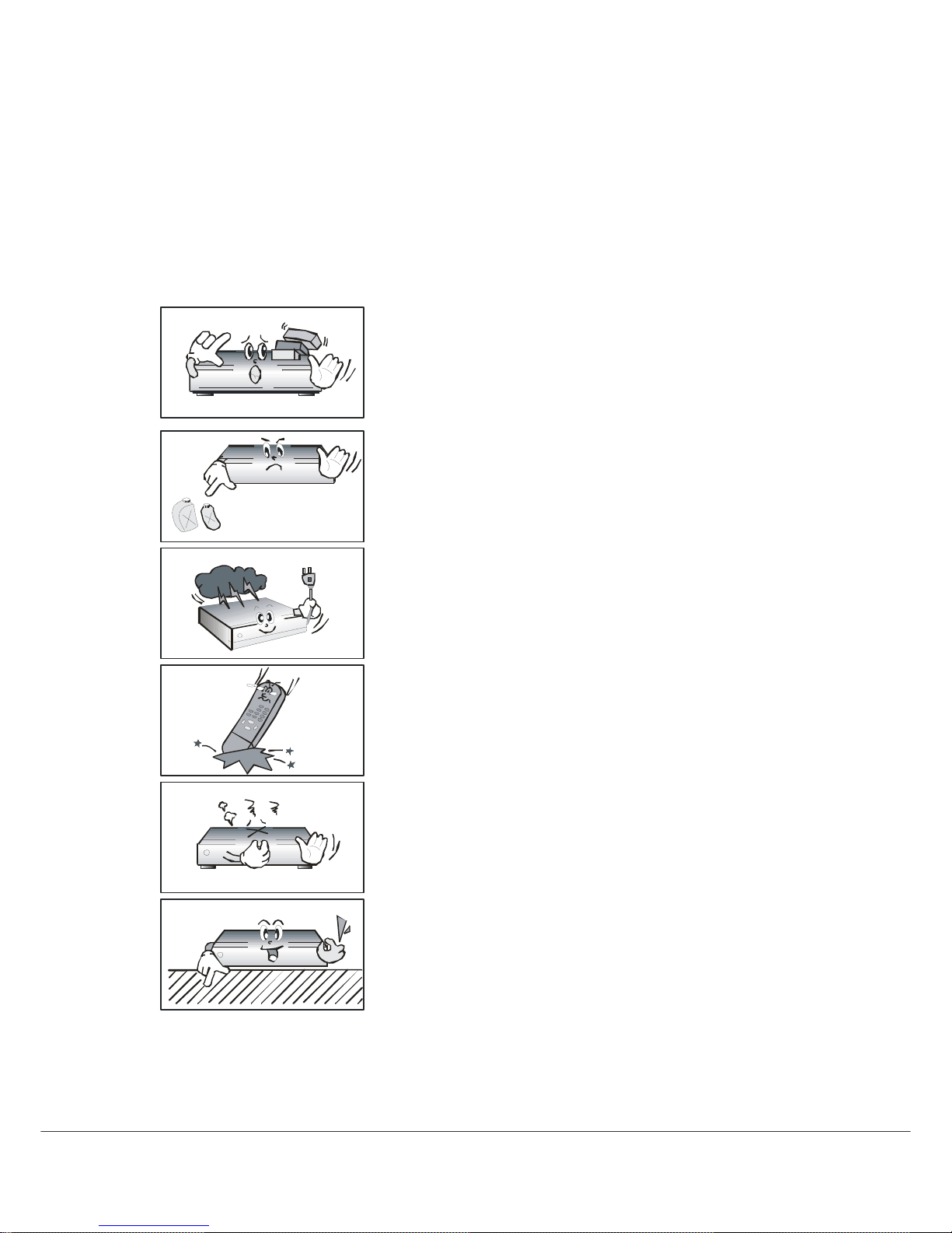
Safety Instructions and Precautions
Avoid placing heavy items on the unit. Ensure that ventilation
holes are not blocked, as this constitutes a serious fire hazard.
Do not clean the unit with petroleum-based cleansers as this
can damage the paintwork. Use a dry, dust-free cloth.
Disconnect the power and antenna cables during long
absences or during electrical storms.
Avoid dropping the Remote Control Unit.
If there is a smoke or burning smell, turn off & unplug the
unit immediately. Contact your local repair centre for advice.
Avoid placing the unit on slippery or sloped surfaces.
5
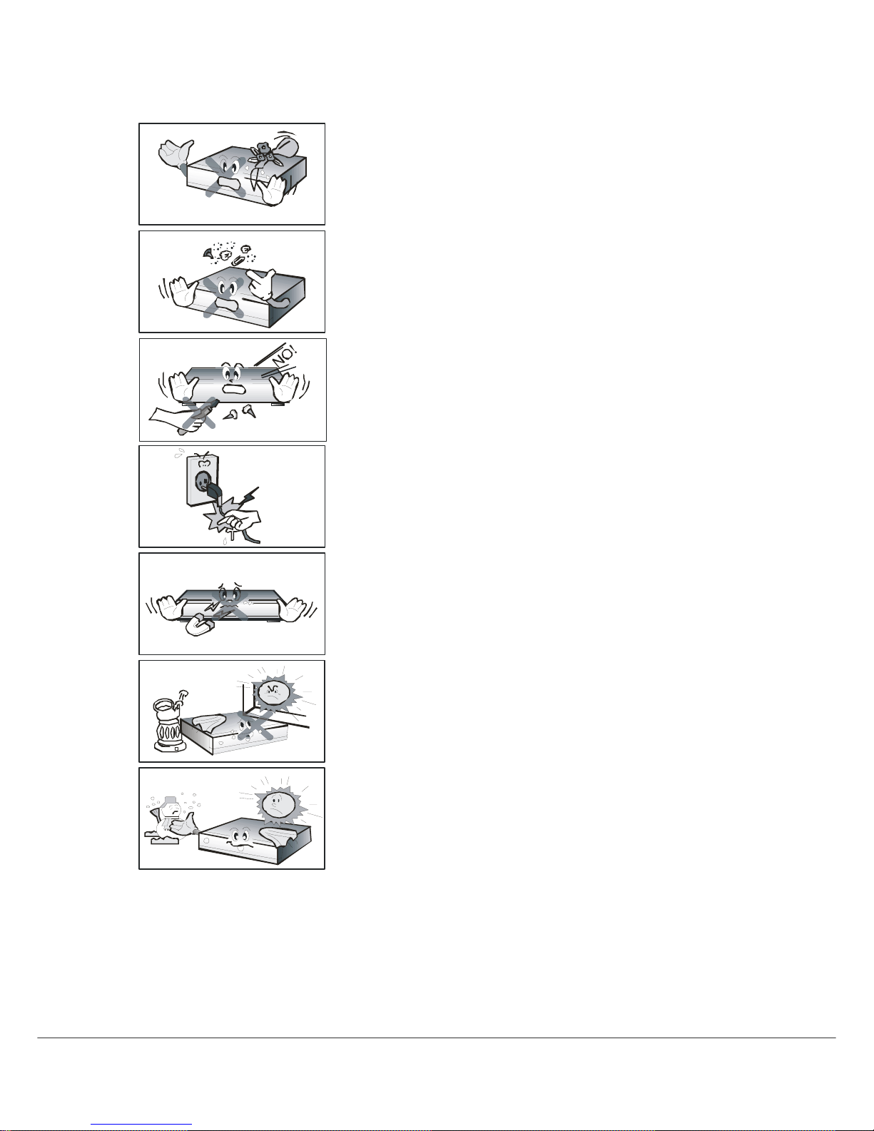
Keep the unit away from all moisture sources.
Keep the unit free of dust. Dust or metallic particles that
find their way into the unit can cause fire or electric shock.
Do not open the unit. It contains no user-serviceable parts.
Do not unplug the unit by grabbing the cord. Turn off the
power at the point, and firmly pull the plug. Do not move
the unit while the power cord is plugged in.
Ensure that the unit is kept well away from magnetic
sources such as speakers. These can cause data loss (from
the HDD).
Ensure that the unit is placed in a position that is well-ventilated
and away from direct sunlight or sources of humidity.
Avoid use if the room air temperature exceeds 30 C, or
drops below 5 C. Remember that temperatures inside an
enclosed cabinet can be much higher. The HT9200DTR’s max.
operating temperature is 45 C.

6
1. Before You Begin
1.1 Features
Tw o Tuners
Two recording and playback simultaneously
Brilliant On Screen Graphic
MPEG-2 Video(MP@ML), MPEG-1 Audio Layer1, Layer2, H.264/AVC, AC3(Dolby Digital),
MPEG2/4 AAC
Digital Tuner with Loop-through
Wide Symbol Rate 7Mbps & Frequency Input 470~860MHz
User friendly OSD menu with full function
Vector Font and 256 color GUI(Graphic User Interface)
VFD (Vacuum Fluorescent Display)
Variable aspect ratio(4:3, 16:9) with Pan Vector or Letter Box
Teletext and Subtitle supported(VBI & OSD)
Installation by Easy Setup Guide
Favorite Channel and Parental Lock Function
OTA supported
USB2.0 port or RS232C port for upgrading system software
HDMI (High Definition Multimedia Interface) supported
USB 2.0 Host & Slave supported
LAN port(RJ-45) for future feature
500GB HDD
Bookmarking & jump function
MHEG-5: Access to a free 8-days Freeview EPG and ability to access interactive TV
contents

7
1.2 Accessories
Component cable
Composite cable
HDMI cable
User’s Manual
Remote Control
AAA dry cell batteries x 2
8
2. Controls and Functions
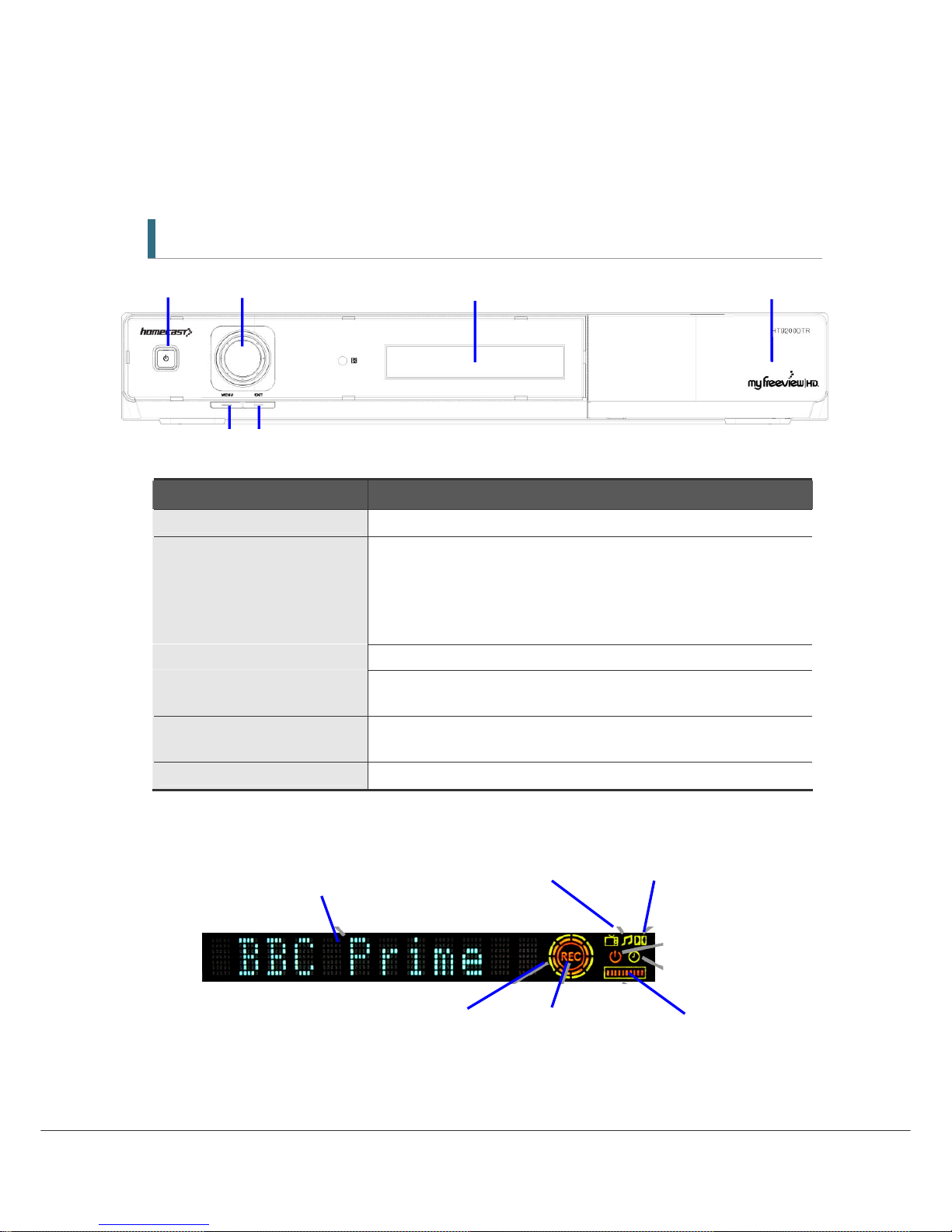
2.1 Front Panel
① ② ⑤ ⑥
③ ④
Item Description
1. Power Button Turns the receiver On/Off (Standby mode).
2. Jog Shuttle ① Increases/ decreases the volume levels in viewing mode.
② Pushing this to go to the channel list in viewing mode.
③ Moves the cursor up/down or left/right in menu mode. To transfer
moving the cursor between up/down and left/right, push the Menu
button.
3. Menu Button Shows the Main menu in viewing mode.
4. EXIT Button Exit from the current menu or cancels the current operation, if
applicable.
5. Display (VFD module) Shows channel information and indicate operating status. In STAND BY
mode, the display shows local time.
6. USB 2.0 Connector USB 2.0 Host is behind the panel door
VFD Elements and Indicators
Channel name, operating status or TV/Radio Dolby Audio
the time date is shown here
Standby
Time Activity
Animated rings indicate Timeshift Active Recording HDD Capacity
or Other HDD activity
9
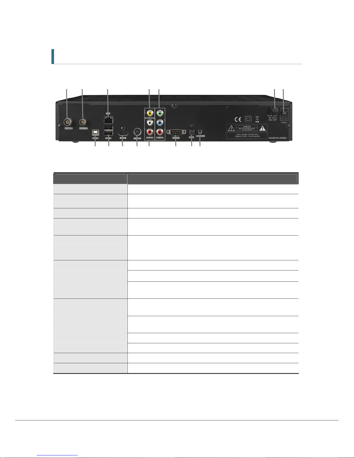
2.2 Rear Panel
1 2 3 4 5 6 7
8 9 10 11 12 13 14 15
8 9 10 11 12 13 14 15
Item Description
1. SIGNAL IN Connect the Antenna In Cable.
2. LOOP OUT
Loop Out is pass-through connector for your antenna signal. Connect
other equipment needing an antenna connection to this connector.
3. LAN PORT Network Interface
4. CVBS OUT Use this to connect a composite video cable (CVBS- Yellow). Standard
definition only (576i resolution).
5. YPbPr OUT Use these jacks to connect Y/Pb/Pr(Green, Blue, Red) component cables
to a component video input on your TV. (576p and 576i resolution only
supported due to copy protection specification)
6. Electric Inlet Lead 90~240V AC(Auto-selectable), 50~60Hz.
7. Power Switch
Turn P ower to th e u n its On/O f f
8. 9. USB2.0 USB2.0 Connector. 8- Slave (to computer) 9. Host ports
*A third Host port is behind the panel door at the right front of unit.
10. HDMI OUT Connect to an HDMI input of TV or PC monitor.
1080i, 720p, 576p resolutions supported
11. S-VIDEO Connect to an S-VIDEO jack on you TV. Standard definition only(576i
resolution).
12. Audio OUT Connect L/R (White/Red) analog audio cables to your TV or amplifier.
13. RS-232C Connects to another HT9200DTR or a PC serial port.
14. S/PDIF Digital audio output for connection to an amplifier(or TV).
15. IR SENSOR Connect the Infrared Ray sensor to extend Remote Control range.
10
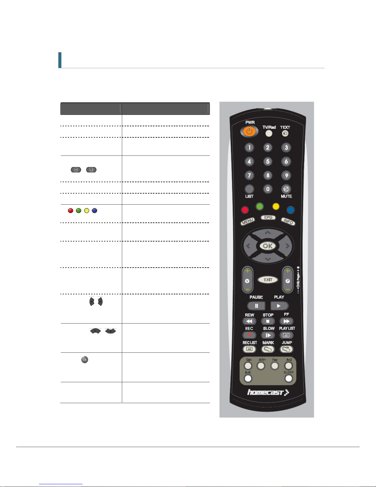
2.3 Remote Control Unit
All receiver features can be controlled with the remote controller.
Button Description
POWER Turn s t he recei ver On/Of f.
TV/Rad Switches between TV and Radio.
TEXT Operates MHEG5 functions when
Service is available
NUMERIC Buttons
(
~ )
Select channels or can use as an
alphabetic search key in the
sorted channel lists.
LIST Display the channel list
MUTE Turns the sound on/off.
Moves in MHEG5 EPG Menu, REC
list and Playing List
MENU Display/ Exit the main menu. Exit
to main menu from the sub-menu
EPG Shows MHEG5 Electronic Program
Guide (EPG) - The Freeview
Guide.
Info Shows the Channel information
bar and extended program
information
◀/▶ ( / )
Moves left/right in menu mode
and change the settings in menu
mode.
▲/▼ ( / )
Moves up/down in menu mode
and change the settings in menu
mode.
OK( )
Confirms the choices and/or
selections the highlighted menu
item.
V+/-
Changes the volume level in
viewing mode.

11
Button Description
EXIT
Go back step one menu level, cancel an operation, or exit from menu.
P+/-
Changes channels in viewing mode.
Selects sub-pages in main menu.
PAUSE Pauses and resume playback, recording and time shift buffer.
PLAY Plays the recorded file.
REW Rewind playback(recording or time-shift). Repeated presses accelerate rewind
speed.
STOP Stop playback, recording and clears time shift buffer.
FF Fast forward playback (and time-shift). Repeated presses accelerate FFWD
speed.
REC Records the channel being viewed.
SLOW Playback in slow mode. Repeated presses change the speed.
PLAY LIST Displays the File list of recorded contents or being recorded ones
REC LIST Displays the File list of the programmes or series booked for recording
(reservation).
MARK Sets a bookmark.
JUMP Jump to a bookmark.
Opt Selects options such as Audio Language, Teletext Language, Subtitle
Language and Multifeed.
A/V+ Select video mode (4:3, 4:3 Letter Box, 16:9) and audio mode (Left, Right,
Stereo and Joint).
Fav Selects from groups of favorite channels.
A-Z Sorts Channel list, REC List, Play List alphabetically or numerically
A-B Set the block to repeat, copy and cut.
SLEEP Put units in Standby mode. Press repeatedly to adjust in 30 minutes
increments.
2.4 Extending the Range of the RCU
Your HT9200DTR is shipped with a small half-dome IR Sensor, on the end of a 2 meter cable. This
allows you to house the HT9200DTR inside a (well ventilated) cabinet, without compromising on
the unit responsiveness to remote commands.
12
3. Connections
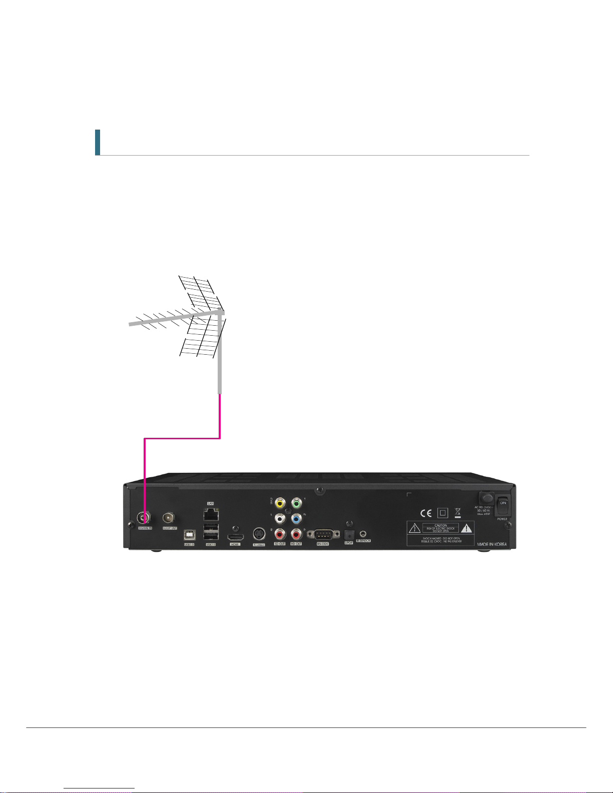
3.1 Connecting to the Antenna
<Making Antenna connections>
1. Connect the antenna cable (75 ohm co-axial) to the SIGNAL IN connector.
2. For passing the antenna signal through to another device (such as a VCR and your TV),
connect an appropriate 75 ohm co-axial cable from the Loop Out connector of HT9200DTR
(The Loop Out connection will pass the antenna signal through to your Device even when
HT9200DTR is in Standby mode (or Turn off at the switch)
13
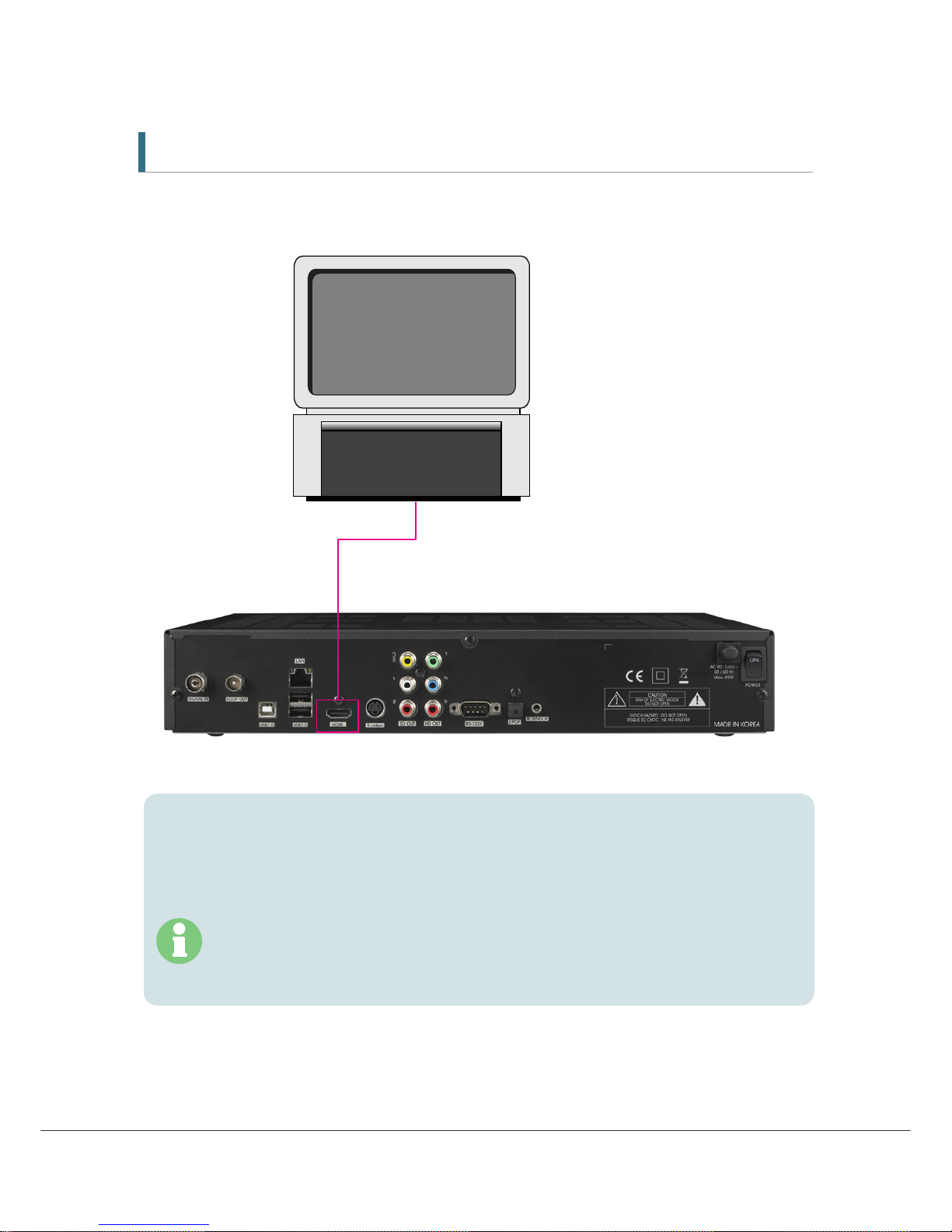
3.2 Connecting to TV
<Connecting to PC monitor or digital TV that has an HDMI input port>
1.
Connect the HDMI output on HT9200DTR to the HDMI input on your monitor or TV.
2.
Set the video output mode to 1080i or 720p or 576p by using ‘Resolution’ in A/V+ on
RCU
For the best access to HD programming at the highest available resolution, use this
connection method.
14
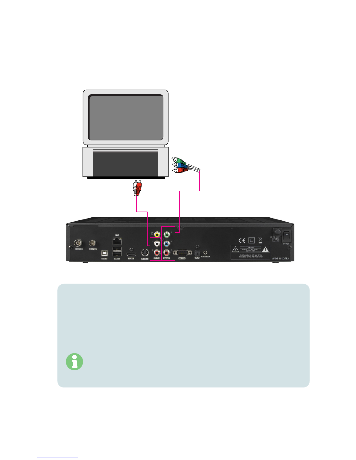
<Connecting to digital TV that supports HD resolution (1080i, 720p,
576p) using the YPbPr port>
1. Connect the YPbPr output on HT9200DTR to a set of matching YPbPr input on your TV.
The Audio L/R out jacks can also be connected to matching jacks on your TV or you can
use the digital audio Out (See Connecting to A/V receiver (Dolby Digital Amplifier) next
page.)
2. Set the video output mode to 1080i or 720p or 576p by using ‘Video Fromat’ in A/V+ on
RCU
For the contents copy protection, YPbPr can support 576p and 576i video output only.
15
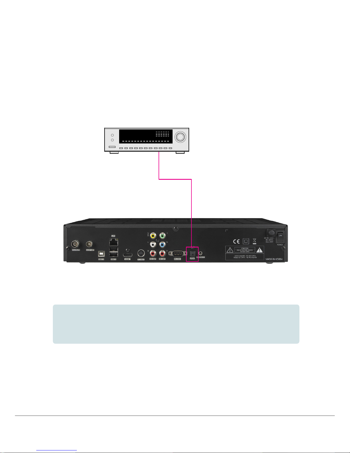
<Connecting to A/V receiver (Dolby digital amplifier)>
1.
Connect the optical digital audio out on HT9200DTR to A/V receiver.
2.
Set the audio out mode as ‘AC3’.
16
4. Menu Overview
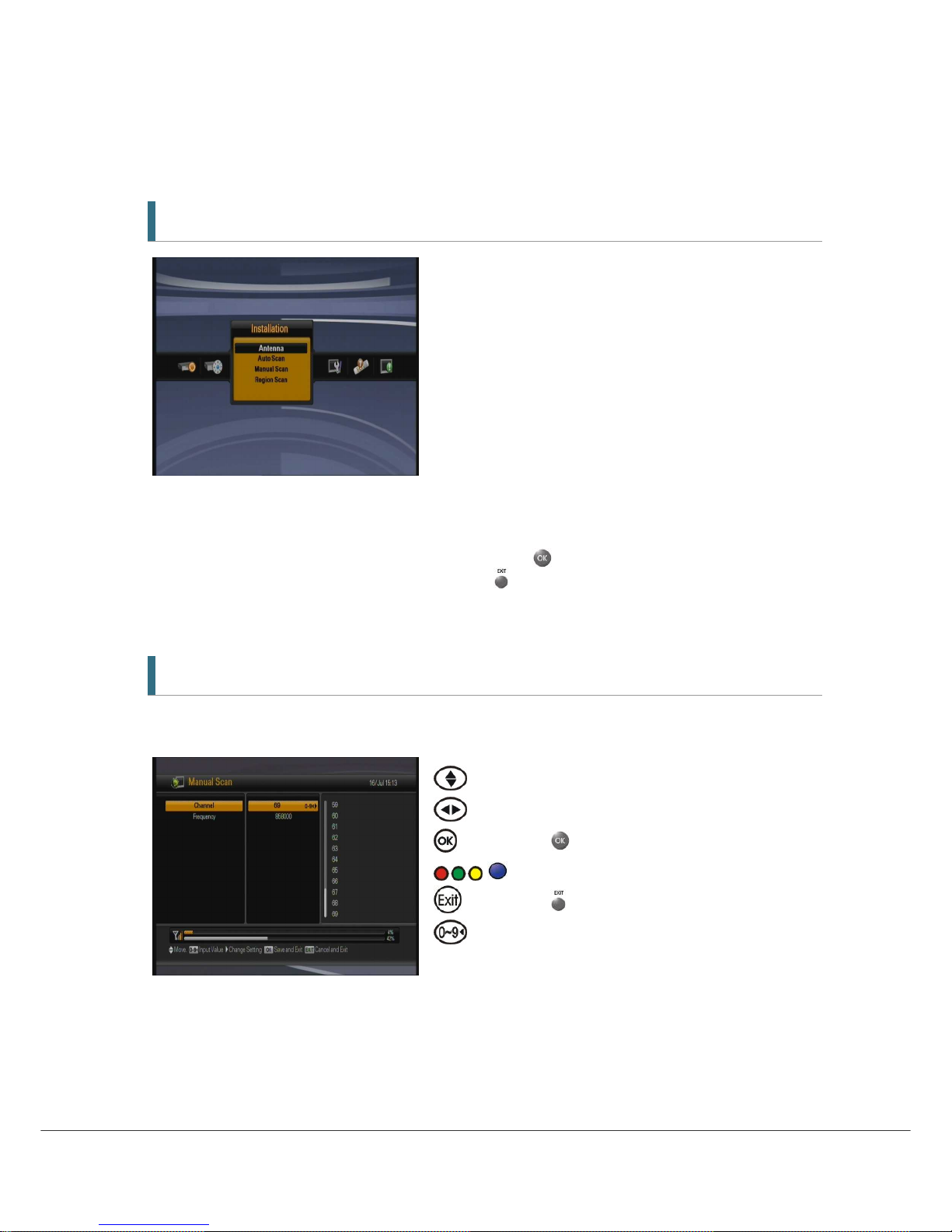
4.1 Menu Instruction
Press the MENU button to display the menu. You can select the sub menu using ▲/▼/◀/▶
button. The selected sub menu becomes highlighted.
When you have selected the sub menu you want, press
button.
If you want to return to the previous menu, press
button.
If you want to return to the live screen, press the Menu button.
4.2 Menu Help
In the menu, short information is displayed at the bottom of the screen.
: Using ▲/▼ button.
: Using ◀/▶button.
: Using
button.
: Moves in MHEG5 EPG Menu
: Using button
: Numerical button
 Loading...