

HOLZMANN MASCHINEN SB 3116RHN, SB 3116RMN User Manual
HOLZMANN-MASCHINEN GmbH
Marktplatz 4 · 4170 Haslach · Austria
Telefon +43.(0) 7289.71562 -0
Telefax +43.(0) 7289.71562 -4
Email info@holzmann-maschinen.at
www.holzmann-maschinen.at
Revision 1 / 12.12.2011
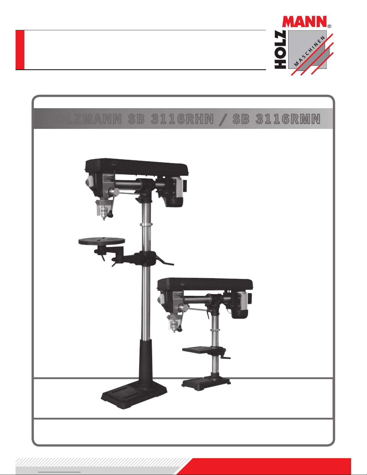
HOLZMANN SB 3116RHN / SB 3116RMN
Bedienungsanleitung Ständerbohrmaschine
User Manual drill press
www.holzmann-maschinen.at
Dear Customer!
This manual contains Information and important instructions for the installation and
correct use of the drill press SB 3116RHN.
This manual is part of the machine and
shall not be stored separately from the
machine. Save it for later reference and
if you let other persons use the machine,
add this instruction to the machine.
Please read and obey the security
instructions!
Before rst use read this manual carefully.
It eases the correct use of the machine
and prevents misunderstanding and damages of machine and the user’s health.
Due to constant advancements in product
design construction pictures and content
may diverse slightly. However, if you discover any errors, inform us please.
Technical specications are subject to
changes!
Copyright © 2011
This document is protected by international copyright law. Any unauthorized
duplication, translation or use of pictures,
illustrations or text of this manual will be
pursued by law – court of jurisdiction is
A-4020 Linz, Austria!
Contact adress:
HOLZMANN MASCHINEN GmbH
4170 Haslach
Marktplatz 4
Tel.: +43 (0) 7289 71562 0
Fax: +43 (0) 7289 71562 4
MO-FR 8:00-12 & 13:00-17:00 GMT +1
Sehr geehrter Kunde!
Diese Bedienungsanleitung enthält Informationen und wichtige Hinweise zur Inbetriebnahme und Handhabung der Ständerbohrmaschine SB 3116RHN . Die
Bedienungsanleitung ist Bestandteil der
Maschine und darf nicht entfernt werden.
Bewahren Sie sie für spätere Zwecke auf
und legen Sie diese Anleitung der Maschine bei, wenn sie an Dritte weitergegeben
wird!
Bitte beachten Sie die Sicherheitshinweise!
Lesen Sie vor Inbetriebnahme diese Anleitung aufmerksam durch. Der sachgemäße
Umgang wird Ihnen dadurch erleichtert,
Missverständnissen und etwaigen Schäden wird vorgebeugt. Halten Sie sich an
die Warn- und Sicherheitshinweise. Missachtung kann zu ernsten Verletzungen
führen.
Durch die ständige Weiterentwicklung unserer Produkte können Abbildungen und
Inhalte geringfügig abweichen. Sollten Sie
jedoch Fehler feststellen, informieren Sie
uns bitte.
Technische Änderungen und Irrtümer vorbehalten!
Urheberrecht © 2011
Diese Dokumentation ist urheberrechtlich
geschützt. Die dadurch verfassungsmäßigen Rechte bleiben vorbehalten! Insbesondere der Nachdruck, die Übersetzung
und die Entnahme von Fotos und Abbildungen werden gerichtlich verfolgt – Gerichtsstand ist A-4020 Linz, Austria!
Kontakt:
HOLZMANN MASCHINEN GmbH
4170 Haslach
Marktplatz 4
Tel.: +43 (0) 7289 71562 0
Fax: +43 (0) 7289 71562 4
MO-FR 8:00-12 & 13:00-17:00 GMT +1
ENGLISH
DEUTSCH
1
2
3
4
5
7
8
6
9
10
11
12
13
14
15
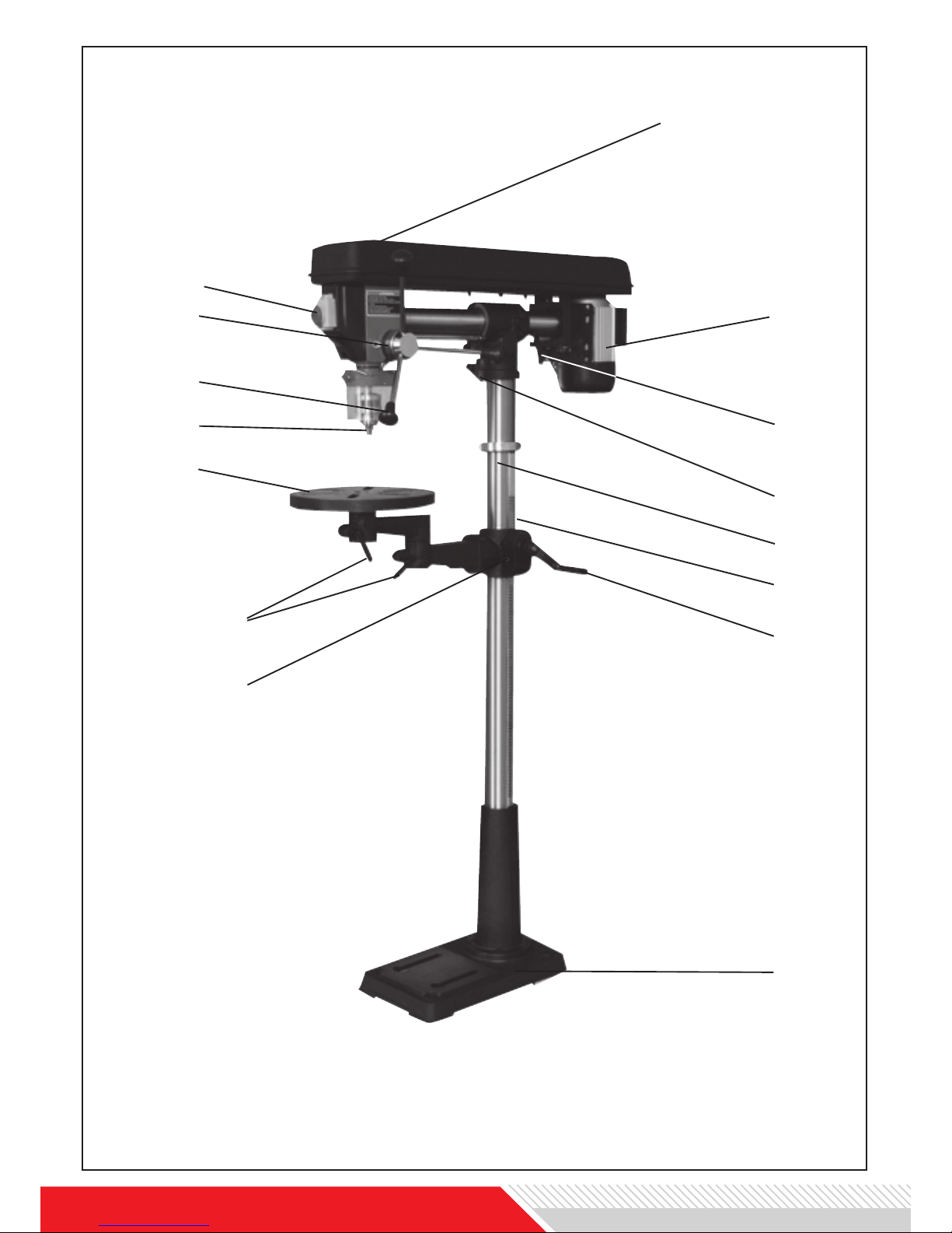
Abb. 1.1/Fig. 1.1
SB 3116RHN
www.holzmann-maschinen.at
1
2
3
4
5
7
8
6
9
10
11
12
13
14
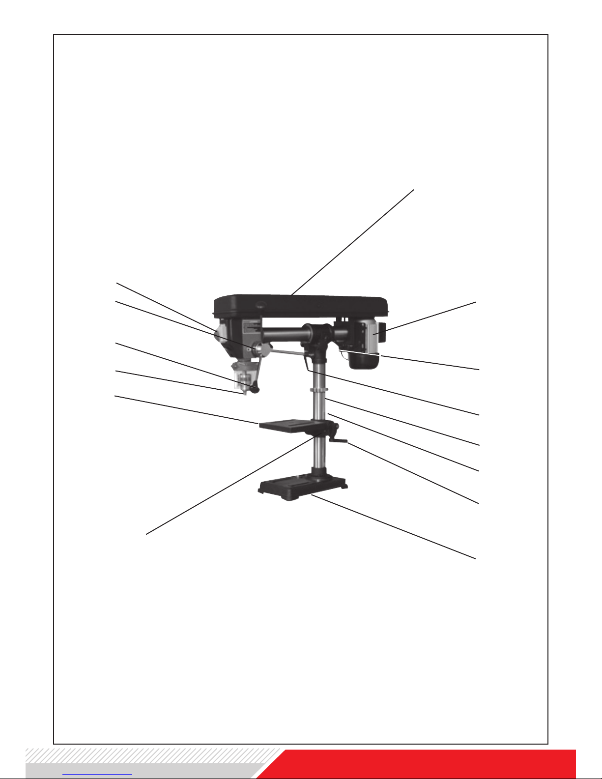
Abb. 1.2/Fig. 1.2
SB 3116RMN
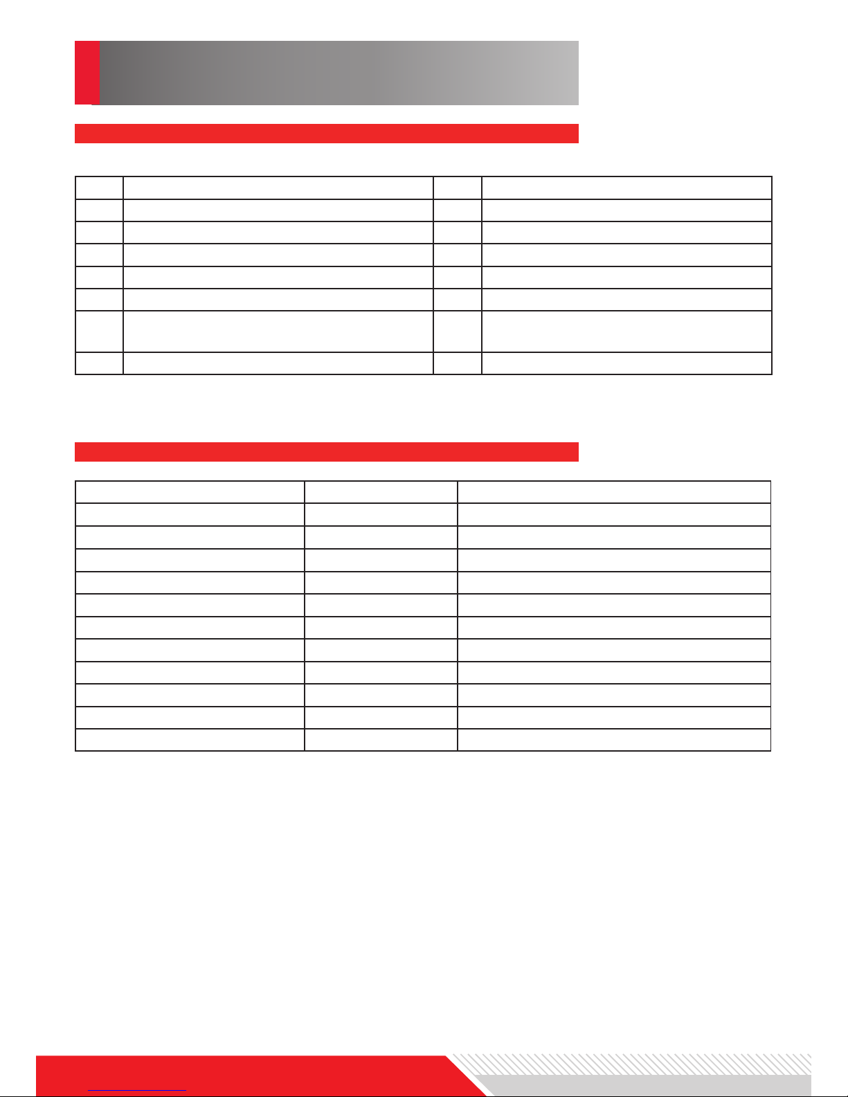
1. TECHNIQUE
Description to SB 3116RHN Fig. 1.1
Technical Details SB 3116RHN
max. drilling capacity
mm 16
spindle speeds
rpm (5) 500-2500
voltage
V 400 oder 230
distance spindle to column
mm 430
spindle holder
MT2
max. spindle travel
mm 80
max. distance chuck to table
mm 825
max. distance chuck to base
mm 1315
table dimensions
Ø300
base
mm 456x280
motor power S1(100%)
W 600
net weight
kg 58
1 pulley cover 9 table bracket
2 motor 10 clamping lever
3 clamping lever for radial adjustment 11 table
4 clamping lever 12 drill chuck
5 column 13 feed lever
6 rack 14 scale ring
7 handle 15 On/Off/ switch and emergency
stop
8 base
The SB 3116RHN is a very solid radial drill - due to various setting possibilities it can be
used for various tasks.
• Head can be moved around within 320mm back and forth.
• Head can be tilted 45° clockwise and 90° counterclockwise.
• Head can be turned round within 360°.
• It can be locked at any position within the adjustable angle.
• Speed can be changed at 5 levels

www.holzmann-maschinen.at
Description to Fig. 1.2 SB 3116RMN
Technical Details SB 3116RMN
max. drilling capacity
mm 16
spindle speeds
rpm (5) 500-2500
voltage
V 230 oder 400
distance spindle to column
mm 430
spindle holder
MT2
max. spindle travel
mm 80
max. distance chuck to table
mm 320
max. distance chuck to base
mm 475
table dimensions
mm
215x225
base
mm 350x215
motor power S1(100%)
W 600
net weight
kg 40
1 pulley cover 9 table bracket
2 motor 10 table
3 clamping lever for radial adjustment 11 drill chuck
4 clamping lever 12 feed lever
5 column 13 scale ring
6 rack 14 On/Off/ switch and emergency
stop
7 handle
8 base
The SB 3116RMN is a very solid table radial drill - due to various setting possibilities it
can be used for various tasks.
• Head can be moved around within 320mm back and forth.
• Head can be tilted 45° clockwise and 90° counterclockwise.
• Head can be turned round within 360°.
• It can be locked at any position within the adjustable angle.
• Speed can be changed at 5 levels
2. SAFETY
Read and understand the owner’s manual and labels afxed to
the machine. Learn the machines application eld and limitations as well as the specic potential hazards peculiar to it.
Keep working area and the ground clean and free of oil and other
materials!
Assure that the working area is sufciently lighted!
Don’t use the machine outside!
The use of the machine is forbidden if you are tired, not con-
centrated as well if you are under the inuence of medicaments,
alcohol and other drugs. Reduce distraction sources in the working area.
BEWARE: Routine leads to insufcient attention.
The machine shall be used only by trained persons wiht an age
of at least 18 years.
Non authorized personnel, especially children, shall be kept away
from the machine! Make your workshop childproof.
When working with the machine, don’t wear loose clothing, long
hair openly or loose jewellery like necklaces etc. Loose objects
might be catched by rotating parts and cause serious injuries.
Use proper safety clothing and devices when operating the machine (safety glasses, ear protectors)!
Assure yourself that your feeding current complies with the requirements of the motor - check the typeplate.
Electric checks and the electric installation of the machine may
only be performed by a qualied electrician.
DO NOT touch leading machine parts.
Prior to any Cleaning, checks, maintenance or tool change shut
the machine off and disconnect it from the power supply in order
to prevent unintended start up of the machine.
In the event of a malfunction or breakdown, grounding provides
a path of least resistance for electric current to reduce the risk of
electric shock. The plug must be plugged into a matching outlet
that is properly installed and grounded in accordance with all
local codes and ordinances. Improper connection of the equipment-grounding conductor can result in a risk of electric shock.
Check with a qualied electrician whether the machine is grounded properly.
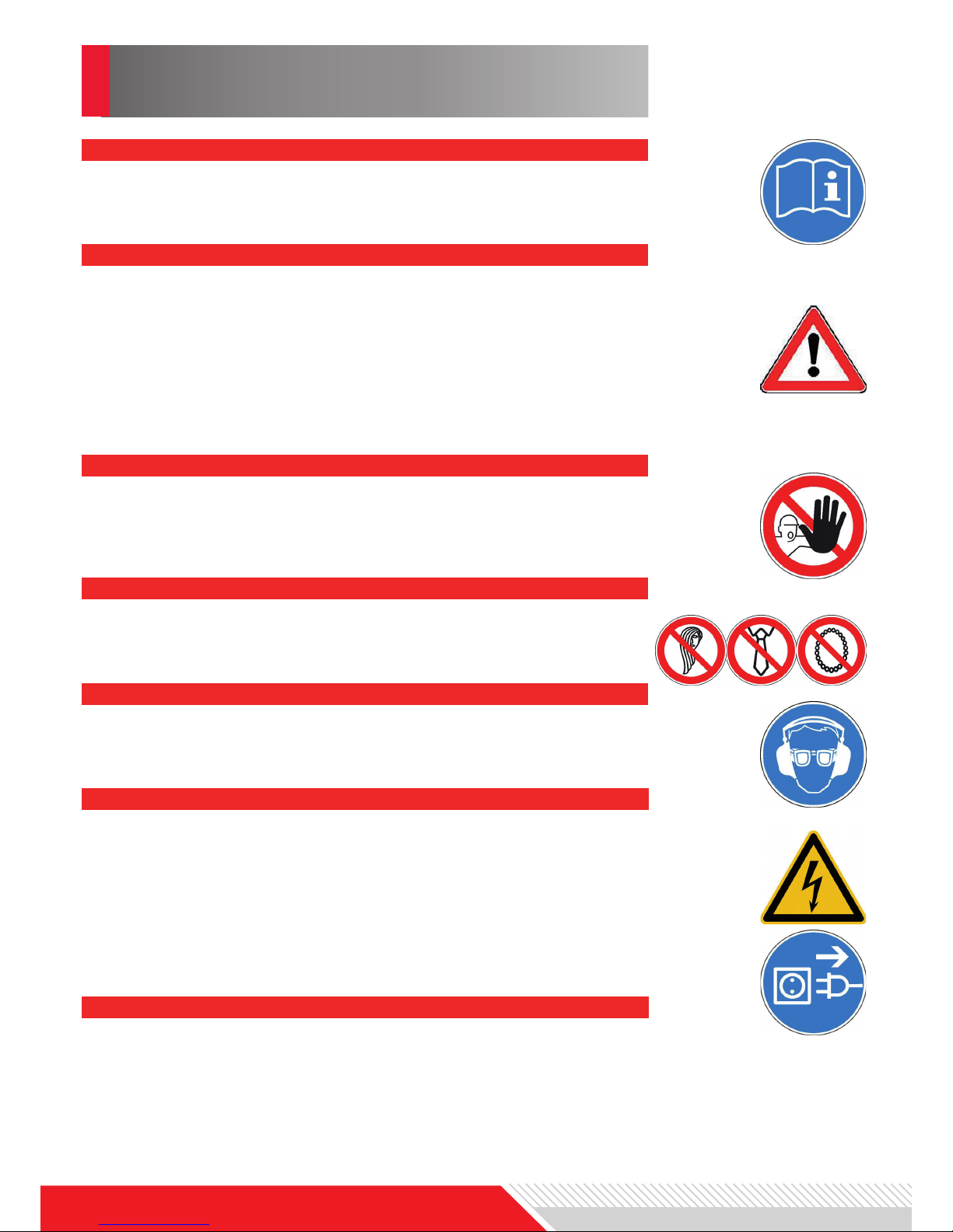
READ THE MANUAL
AVOID DANGEROUS CONDITIONS
OPERATOR
CLOTHING
SAFETY EQUIPMENT
ELECTRIC CONNECTION
GROUNDING

www.holzmann-maschinen.at
Form a habit of checking to see whether adjusting keys, wrenches and other objects are removed from the machine before turn-
ing it on.
It will do a better job when being used within its power range it
has been constructed for. Do not misuse the machine or parts of
it for jobs for which it was not intended.
Make sure your extension cord is in good condition. When using
an extension cord, be sure to use one with sufcient cross-section to carry the current your machine will draw. An undersized
cord will cause a drop in the line voltage resulting in power loss
and overheating.
Use only accesories matching with the machines specications
and being suitable for the use with the machine. Especially important are the max. allowed revolution speeds for which the
accesory is allowed to be used. Use only Accesories whose max.
allowed revolution speed is higher than the max. speed of the
machine you intend them to use with.
Do not drill workpieces that are too small to be supported safely.
For smaller workpieces you should install a vice onto the working
table and support the workpiece with the vice.
SOME DUST CREATED by power sanding, sawing, grinding, drilling and other construction activities contains chemicals known to
cause cancer, birth defects or other reproductive harm. Some
examples of these chemicals are:
• Lead from lead based paint
• crystalline silica from bricks and cement and other masonry
products, and
• arsenic and chromium from chemically-treated lumber.
• Your risk from those exposures varies, depending on how of-
ten you do this type of work. To reduce your exposure to these
chemicals: work in a well ventilated area, and work with approved safety equipment, such as those dust masks that are
specically designed to lter out microscopic particles.
Finally obey all general working safety rules imperative when
operating a machine and follow all rules and regulations being
in power in your country regarding safety at work, accident pre-
vention, rst aid, re prevention.
DO NOT FORCE THE MACHINE
USE PROPER EXTENSION CORD
USE ONLY RECOMMENDED AND SAFE ACCESORIES
DRILL SAFETY
HAZARD FROM DUST
REMOVE ADJUSTING KEYS AND WRENCHES
WORK SAFETY RULES

Take care to remove the Chuck key from the drill chuck before
turning the machine on.
The drill bit shall not touch the workpiece when turning the machine on.
Especially workpieces with not even surface have to be clamped
by a vice.
Never change, remove, adjust workpiece while machine is running.
The work with a drill press always incorportates some remaining
risks which can never be eliminated entirely and the operator
should be aware of:
Hazard of severe injury when touching the rotating drill bit, drill
chuck or spindle.
Hazard of cutting injury caused by sharp drill edges or sharp
metal chips.
Hazard of injury through material or parts of the workpiece being catapulted away.
The drill press is equipped with an ON/OFF switch with a emergency OFF cap activating the red OFF button when being depressed.
The drill press has an automatic OFF switch which is activated as
long as the drive belt cover is not closed entirely
The drill press is equipped with a chip protection cover which
should be always used when performing drills.
REMAINING RISKS
SECURITY DEVICES
DRILL SPECIFIC SAFETY RULES
www.holzmann-maschinen.at
Unpack and separate all parts from packaging material and check if the delivery content
is complete. For checking refere to Fig. 3, Fig. 4 and Fig. 5 .
Please report eventual missing or damaged parts immediately to your reseller.
Later claims from transport damage cannot be accepted anymore.
DELIVERY CONTENT
Assembly hardware is located in one box
and one bag. Each contains the necessary
parts for each assembly step. Remove all
packing and protective material from the
Drill Press components. To aid in assembly, refer to the Assembly Drawing Fig. 2
as well as to the parts drawings at the end
of this manual. The machine assembly is
shown on basis of the model SB 3116RHN.
1. Position the Base (B6) on a level and
sturdy oor for mounting.
Bolt the Base to the oor using appropri-
ate hardware (not supplied). Base holes
will accommodate 7/16 inch bolts. Pull out
the Wire Stabilizer (B21) rod from the rear
of the Base.
2. Place the Column Support (B4) on the
Base, aligning the mounting holes.
ASSEMBLY
3. SETUP
3. Insert four large Hex Screws (B5) into
the mounting holes and tighten with a
wrench.
4. Insert the Column (B1) into the Column
Support (B4) and secure with Screw (B3).
5. Install the Table Support (B7), with attached table Arm (B14), over the Column
(B1) and slide it down. Engage the gears onto the Rack (B2). Tighten the Table
Clamp (B13).
6. Slide the Column Collar (B19) over and
down the Column (B1) about 8 inches.
Tighten Screw (B11).
7. Place the Extend Arm (B15) into the
Arm (B14), and then the Table (B20) into
the opening in the Extend Arm.
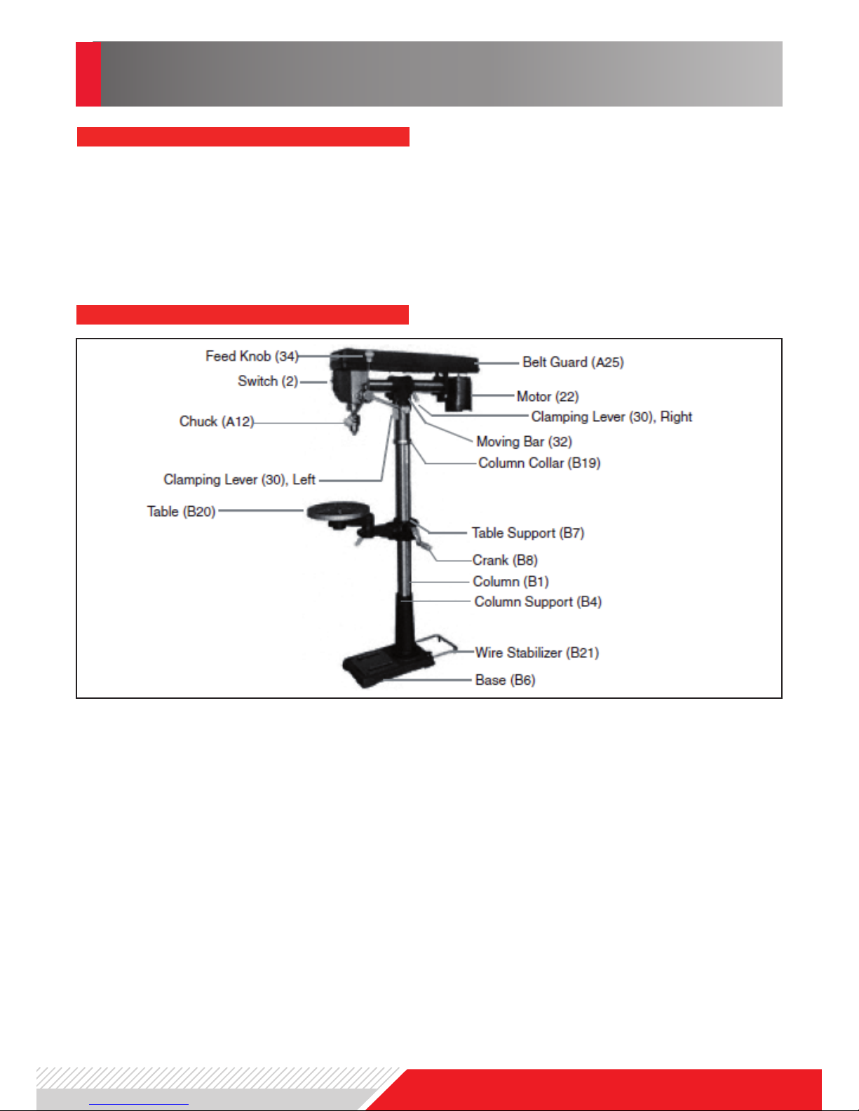
Abb. 2/Fig. 2
CAUTION:
Avoid injuries. The next step involves
lifting the Head Assembly onto the
Column. The Head Assembly is heavy.
Have someone help you lift this assembly into place.
8. Using two people, lift the Head Assembly and insert the Column Guide (18) over
the Column (B1).
Slide it down on the Column Tube as far as
it will go. Align it so that it faces straight
forward, inline with the Base.
9. Insert one Locking Shoe (15) into place
inside the bottom of the Column Guide
(18), and the other on the outside of the
Column Guide. Tighten the Clamping Lever (30) into the Locking Shoe at the base
of the Column Guide.
10. Adjust V-Belt (A1) tension or change
speeds.
- Open the Belt Guard (A25) to expose the
V-Belt.
- Loosen the Thumb Nut (28) to relieve
the V-Belt tension.
- If necessary, move the Belt up or down
on the pulleys to change the drill speed.
- Push the Motor backward, tightening the
Belt on the pulleys, and hold in place.
- Turn the Thumb Nut (28) clockwise to
tighten the V-Belt in place.
- Refer to the chart inside the Guard lid to
select speed and belt locations.
Note: To test the proper belt tension, push
in on the center of each belt at its center.
It should move only 1/2 inch (in or out).
Caution: overtightening the belts can
cause the motor to bind, and not start.
It can also damage Motor bearings.
11. Locate the Feed Knobs (34) and Feed
Rods (35) and screw into the Hub (36).
12. Install the Chuck (A12).
- Thoroughly clean the tapered hole in the
Chuck and the Spindle (A15) shaft of all
dirt, grease, oil, and protective coatings
(paint thinner may be necessary).
- Slide the Chuck onto the Spindle shaft.
- Turn the Chuck sleeve clockwise and
open the jaws completely.
- Tap the nose of the Chuck lightly with a
piece of wood to securely set the Chuck.
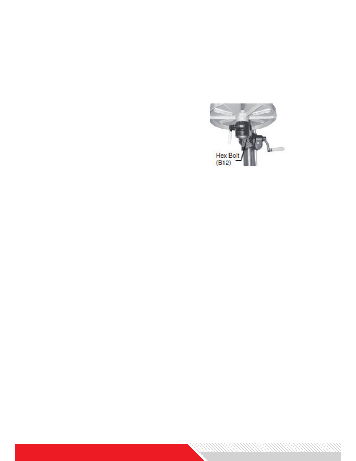
13. Verify that the Table (B20) is square
(90 degrees) to the Head Assembly and
drill bit.
- Raise the Table to within four inches of
the Chuck.
- Place the long side of a combination
square on the Table.
- Align the short side of the square to the
drill bit.
- If the Table is not square to the bit, loosen Hex Bolt (B12) with a wrench.
- Rotate the Table until it is square to the
bit.
- Retighten the Hex Bolt (B12).
 Loading...