

Page 1
ThinPrep
Operator’s Manual
®
Integrated Imager
Page 2

ThinPrep® Integrated Imager
Operator’s Manual
Hologic, Inc.
250 Campus Drive
Marlborough, MA 01752 USA
Tel: 1-800-442-9892
1-508-263-2900
Fax: 1-508-229-2795
Web: www.hologic.com
For Use With Version 1.x.y Software
MAN-05283-001
Page 3

Caution: Federal law restricts this device to sale by or on the order of a physician, or any other practitioner licensed by the law of the State in which the practitioner practices to use or order the use of
®
the device and are trained and experienced in the use of the ThinPrep
Integrated Imager.
The ThinPrep® Integrated Imager is a PC-based automated imaging and review system for use with
ThinPrep cervical cytology sample slides. The ThinPrep Integrated Imager is intended to help a
cytotechnologist or pathologist highlight areas of a slide for further manual review. The Product is
not a replacement for manual review. Determination of slide adequacy and patient diagnosis is at the
sole discretion of the cytotechnologists and pathologists trained by Hologic to evaluate ThinPrepprepared slides. If and only if it is finally determined by a court of competent jurisdiction that the
Product sold to Customer hereunder was defective in design or contained a manufacturing defect
and that such defect was solely responsible for an error in diagnosis that caused harm to a patient,
Hologic shall indemnify Customer for the compensatory damages paid by Customer to discharge
the personal injury judgment with respect to Product.
© Hologic, Inc., 2018. All rights reserved. No part of this publication may be reproduced,
transmitted, transcribed, stored in a retrieval system, or translated into any language or computer
language, in any form, or by any means, electronic, mechanical, magnetic, optical, chemical, manual,
or otherwise, without the prior written permission of Hologic, 250 Campus Drive, Marlborough,
Massachusetts, 01752, United States of America.
Although this guide has been prepared with every precaution to ensure accuracy, Hologic assumes no
liability for any errors or omissions, nor for any damages resulting from the application or use of this
information.
This product may be covered by one or more U.S. patents identified at
http://hologic.com/patentinformation
Hologic, PreservCyt, and ThinPrep are registered trademarks of Hologic, Inc. in the United States
and other countries. All other trademarks are the property of their respective companies.
Changes or modifications to this unit not expressly approved by the party responsible for
compliance could void the user’s authority to operate the equipment.
Document Number: AW-16644-001 Rev. 002
Page 4

Instructions For Use
Instructions For Use
Page 5
Operation Summary and Clinical Information
The ThinPrep® Integrated Imager
Page 6

A. INTENDED USE
The Hologic ThinPrep® Integrated Imager is a device that uses computer imaging technology to assist in
primary cervical cancer screening of ThinPrep
®
Pap Test slides for the presence of atypical cells,
cervical neoplasia, including its precursor lesions (Low Grade Squamous Intraepithelial Lesions, High
Grade Squamous Intraepithelial Lesions), and carcinoma as well as all other cytologic criteria as defined
by the Bethesda System: Terminology for Reporting Results of Cervical Cytology
1
.
B. SUMMARY AND EXPLANATION OF THE SYSTEM
The ThinPrep Integrated Imager is an automated imaging and review system for use with ThinPrep Pap
Test slides. It combines imaging technology to identify microscopic fields of diagnostic interest with
automated stage movement of a microscope in order to locate these fields. In routine use, the ThinPrep
Integrated Imager selects 22 fields of view for a cytotechnologist (CT) to review. Following review of
these fields, the cytotechnologist will either complete the diagnosis if no abnormalities are identified or
review the entire slide if any abnormalities are identified. The ThinPrep Integrated Imager also allows
the physical marking of locations of interest for the cytopathologist.
C. PRINCIPLES OF OPERATION
The ThinPrep Integrated Imager is a combined system which uses computerized image analysis and
automated microscope location to assist a cytotechnologist or pathologist to identify areas of a slide that
are of most interest. Slides used with this system must first be prepared on the ThinPrep
or ThinPrep
be used as a conventional microscope when not used for ThinPrep
®
5000 processors, and stained with ThinPrep® Stain. The ThinPrep Integrated Imager can
®
imaging.
®
2000 System
The ThinPrep Integrated Imager images the entire cell spot of the slide in approximately 90 seconds.
The system acquires and processes image data from the slides to identify diagnostically relevant cells or
cell groups based on an imaging algorithm that considers cellular features and nuclear darkness. During
slide imaging, the alphanumeric slide accession identifier is recorded and the x and y coordinates of
22 fields of interest are stored in the system.
After image processing, the device acts as an automated microscope, presenting the 22 fields containing
the cells of interest to the cytotechnologist for review. The cytotechnologist uses the review control or
touch screen to step through each of the fields of interest (Autolocate). Additionally, the review scope
provides a method for automated marking of objects for further review. If the cytotechnologist identifies
any of these fields as containing abnormal objects, that field may be marked electronically. The
Integrated Imager will guide the cytotechnologist to conduct a review of the entire cell spot for any slide
that has had fields electronically marked (Autoscan).
The cytotechnologist determines specimen adequacy and the presence of infections during the review of
the 22 fields of view presented by the ThinPrep Integrated Imager. Either of two methods can be used to
determine specimen adequacy. The first method is to count cells and determine the average number of
cells in the 22 fields of view presented by the Imager. The second method is to count and determine the
average number of cells in 10 fields of view across the diameter of the cell spot. Either method will
enable the cytotechnologist to determine if the minimum cells, as recommended by Bethesda System
criteria, are present on the slide. At the conclusion of the slide review, electronically marked objects are
manually marked on the slide by the cytotechnologist. Slide information is stored in the computer
database including the x and y coordinates representing the electronically marked locations, and the
status of the slide is designated as “complete”.
MAN-05359-001 -001 Rev. 001 page 2 of 32
Page 7

The cytotechnologist can review the slides immediately after each slide is imaged (sequential modality)
or, as an alternative workflow for labs, slides can be imaged in succession, and coordinates stored in the
computer database for later cytotechnologist or pathologist review (batched modality).
D. LIMITATIONS
Only personnel who have been appropriately trained should operate the ThinPrep Integrated Imager.
All slides that undergo primary automated screening with the Integrated Imager require manual
rescreening of the selected fields of view by a cytotechnologist or pathologist.
The ThinPrep Integrated Imager is only indicated for use with the ThinPrep Pap Test.
The ThinPrep Integrated Imager is only indicated for the ThinPrep Pap Test slides prepared with the
ThinPrep
indicated for the ThinPrep Pap Test slides prepared with the ThinPrep
ThinPrep
®
2000 System and the ThinPrep® 5000 processor. The ThinPrep Integrated Imager is not
®
slides with fiducial marks must be used.
®
3000 processor.
Slides must be stained using the ThinPrep Stain according to the applicable ThinPrep Integrated
Imager slide staining protocol.
Slides should be clean and free of debris before being placed on the system.
The slide coverslip should be dry and located correctly.
Slides that are broken or poorly coverslipped should not be used.
Slides used with the ThinPrep Integrated Imager must contain properly formatted accession number
identification information as described in the operator’s manual.
Slides once successfully imaged on the Integrated Imager cannot be imaged again.
The performance of the ThinPrep Integrated Imager using slides prepared from reprocessed sample
vials has not been evaluated; therefore it is recommended that these slides be manually reviewed.
E. WARNINGS
The Integrated Imager generates, uses, and can radiate radio frequency energy and may cause
interference to radio communications.
A Hologic authorized service representative must install the ThinPrep Integrated Imager.
F. PRECAUTIONS
Caution should be used when loading and unloading glass slides on the ThinPrep Integrated Imager
to prevent slide breakage and/or injury.
The Integrated Imager should be placed on a flat, sturdy surface away from any vibrating
machinery to assure proper operation.
G. PERFORMANCE CHARACTERISTICS
The ThinPrep Integrated Imager is technologically similar to the ThinPrep Imaging System. The
performance characteristics of the ThinPrep Integrated Imager were compared to the ThinPrep Imaging
System in a multi-center clinical study. The ThinPrep
®
Imaging System was compared to Manual
MAN-05359-001 -001 Rev. 001 page 3 of 32
Page 8

Review in a separate multi-center clinical study. Both clinical studies are described in the following
sections.
G.1 ThinPrep Imaging System Compared to Manual Review
A multi-center, two-armed clinical study was performed over an eleven (11) month period at four
(4) cytology laboratory sites within the United States
Center Trial Evaluating the Primary Screening Capability of the ThinPrep
2
. The objective of the study entitled “Multi-
®
Imaging System” was to
show that routine screening of ThinPrep Pap Test slides using the ThinPrep Imaging System is
equivalent to a manual review of ThinPrep slides for all categories used for cytologic diagnosis
(specimen adequacy and descriptive diagnosis) as defined by the Bethesda System criteria
1
.
The two-arm study approach allowed for a comparison of the cytologic interpretation (descriptive
diagnosis and specimen adequacy) from a single ThinPrep-prepared slide, screened first using
standard laboratory cervical cytology practices (Manual Review) and then after a 48-day time lag
were screened with the assistance of the ThinPrep Imaging System (Imager Review). A subset of
slides from the study were reviewed and adjudicated by a panel of three (3) independent
cytopathologists to determine a consensus diagnosis. The consensus diagnosis was used as a “gold
standard” for truth to evaluate the results of the study.
G.1.1 Laboratory and Patient Characteristics
Of the 10,359 subjects in the study, 9,550 met the requirements for inclusion in the descriptive
diagnosis analysis. During the study, 7.1% (732/10,359) slides could not be read on the Imager
and required a manual review during the Imager Review arm. Excessive number of air bubbles
on the slides was the leading contributor. Additional factors included focus problems, slide
density, slide identification read failures, slides detected out of position, multiple slides seated
within a cassette slot and slides that had already been imaged. The cytology laboratories
participating in the study were comprised of four centers. All sites selected had extensive
experience in the processing and evaluation of gynecologic ThinPrep slides, and were trained in
the use of the ThinPrep Imaging System. The study population represented diverse geographic
regions and subject populations of women who would undergo cervical screening with the
ThinPrep Imaging System in normal clinical use. These sites included both women being
routinely screened (screening population) and patients with a recent previous cervical
abnormality (referral population). The characteristics of the study sites are summarized in
Table 1.
MAN-05359-001 -001 Rev. 001 page 4 of 32
Page 9

Table 1. Site Characteristics
Site 1 2 3 4
Screening (Low Risk)
Population
Referral (High Risk)
Population
HSIL+ prevalence
ThinPrep Pap Tests Per Year
Number of Cytotechnologists
Number of Cytotechnologists
in Study
Number of Cytopathologists
Number of Cytopathologists
in Study
88% 82% 90% 94%
12% 18% 10% 6%
1.1% 0.7% 0.4% 0.6%
120,000 70,200 280,000 105,000
14 9 32 11
2 2 2 2
6 5 6 14
1 2 1 2
G.1.2 Descriptive Diagnosis Sensitivity and Specificity Estimates
A panel of three independent cytopathologists adjudicated slides from all discordant (one-grade
or higher cytologic difference) descriptive diagnosis cases (639), all concordant positive cases
(355) and a random 5% subset of the 8550 negative concordant cases (428). The
cytopathologists on the adjudication panel were board-certified, all of whom had a subspecialty
certification in cytopathology. Their experience levels in cytopathology ranged from 6 to 12
years. Two of the adjudicators were from university practices and one adjudicator was from a
private medical center. The volumes for the adjudicators’ institutions ranged from 12,000 to
30,000 ThinPrep Pap Tests annually.
A consensus diagnosis was defined as agreement by at least 2 of 3 cytopathologists. All slides
sent to the panel of cytopathologists were not identified by site nor ordered in any fashion.
When a consensus diagnosis could not be obtained by at least 2 of 3 cytopathologists, the full
panel of cytopathologists reviewed each case simultaneously using a multi-headed microscope
to determine a consensus diagnosis.
The adjudicated results were used as a “gold standard” to define the following major “true”
descriptive diagnosis classifications of the Bethesda System: Negative, ASCUS, AGUS, LSIL,
HSIL, Squamous Cell Carcinoma (SQ CA) and Glandular Cell Carcinoma (GL CA). Estimates
of sensitivity and specificity together with 95% confidence intervals were calculated for the
Manual Review and Imager Review arms of the study. The differences in sensitivity and
specificity between the two arms, together with their 95% confidence intervals were also
calculated. Among the random 5% subset of 8,550 cases (428 slides) that were found to be
negative by both arms and adjudicated, there were 425 “true” negative and 3 “true” ASCUS
slides. A multiple imputation technique was used to adjust the numbers of true positives and
true negatives for the 8,550 negative concordant cases based on the 5% of cases that were
adjudicated
2
.
Table 2 summarizes the descriptive diagnosis sensitivity and specificity estimates with 95%
confidence intervals for all sites combined for “true” ASCUS+, LSIL+ and HSIL+.
MAN-05359-001 -001 Rev. 001 page 5 of 32
Page 10

Table 2. Manual Review Versus Imager Review, Descriptive Diagnosis Summary
Sensitivity Specificity
Threshold
ASCUS+
LSIL+
HSIL+
UNSAT
Manual
(95% CI)
75.6%
(72.2% to 78.8%)
79.7%
(75.3% to 83.7%)
74.1%
(66.0% to 81.2%)
29.3%
(18.1% to 42.7%)
Imager
(95% CI)
82.0%
(78.8% to 84.8%)
79.2%
(74.7% to 83.2%)
79.9%
(72.2% to 86.2%)
13.8%
(6.1% to 25.4%)
Difference
(95% CI)
+6.4%
(2.6% to 10.0%)
-0.5%
(-5.0 % to 4.0%)
+5.8%
(-1.1% to 12.6%)
-15.5%
(-25.9% to 5.0%)
Manual
(95% CI)
97.6%
(97.2% to 97.9%)
99.0%
(98.8% to 99.2%)
99.4 %
(99.2% to 99.6%)
99.5%
(99.3% to 99.6%)
Imager
(95% CI)
97.8%
(97.4% to 98.1%)
99.1%
(98.9% to 99.3%)
99.6%
(99.5% to 99.7%)
99.8%
(99.7% to 99.9%)
Difference
(95% CI)
+0.2%
(-0.2% to 0.6%)
+0.09%
(-0.1% to 0.3%)
+0.2%
(0.06% to 0.4%)
+0.3%
(0.2% to 0.4%)
The results presented in Table 2 show that for ASCUS+, the increase in sensitivity of the Imager
Review over the Manual Review was statistically significant with the lower limit of the 95%
confidence interval being 2.6% for all sites combined. The observed difference between
sensitivities for ASCUS+ varied among the sites from –2.8% with a 95% confidence interval of
(–10.6%; 5.0%) to +14.4% with a 95% confidence interval of (8.2%; 20.5%). The difference in
specificity results between the Imager Review and the Manual Review was not statistically
significant with a 95% confidence interval of –0.2% to +0.6%. The observed differences
between specificities varied among the sites from –0.3% to +0.4%.
The results presented in Table 2 show that the difference between sensitivities of the Imager
Review and Manual Review arms for LSIL+ for all sites combined was not statistically
significant with a 95% confidence interval of –5.0% to +4.0%. The observed difference between
sensitivities for LSIL+ varied among the sites from –6.3% with a 95% confidence interval of
(–14.7%; 2.1%) to +8.1% with a 95% confidence interval of (–4.0%; 20.1%). The difference in
specificity results between the Imager Review and the Manual Review was not statistically
significant with a 95% confidence interval of –0.1% to +0.3%. The observed differences
between specificities varied among the sites from –0.4% to +0.6%.
The results presented in Table 2 show that the difference between sensitivities of the Imager
Review and Manual Review arms for HSIL+ for all sites combined was not statistically
significant with a 95% confidence interval of –1.1% to +12.6%. The observed difference
between sensitivities for HSIL+ varied among the sites from –2.5% with a 95% confidence
interval of (–15.4%; 10.4%) to +13.6% with a 95% confidence interval of (–0.7%; 28.0%). The
increase in specificity of the Imager Review over the Manual Review was statistically significant
with a 95% confidence interval of +0.06% to +0.4%. The observed differences between
specificities varied among the sites from –0.1% to +0.7%.
Table 3 shows the unadjudicated marginal frequencies data for benign cellular changes for all
sites combined.
MAN-05359-001 -001 Rev. 001 page 6 of 32
Page 11

Table 3. Unadjudicated Marginal Frequencies – Summary of Descriptive Diagnosis
for Benign Cellular Changes – All Sites Combined
Manual Review Imager Review
Number of Patients: 9550 9550
Descriptive Diagnosis N % N %
Benign Cellular Changes: 405 4.2 293 3.1
Infection:
Trichomonas Vaginalis 8 0.1 8 0.1
Fungal organisms consistent with Candida spp. 47 0.5 31 0.3
Predominance of coccobacilli 71 0.7 60 0.6
Bacteria consistent with Actinomyces spp. 1 0.0 1 0.0
Cellular Changes associated with Herpes virus 1 0.0 1 0.0
Other Infection 1 0.0 0 0.0
Reactive Cellular Changes Associated with:
Inflammation 218 2.3 156 1.6
Atrophic with inflammation (atrophic vaginitis) 68 0.7 46 0.5
Radiation 0 0.0 0 0.0
Intrauterine contraceptive device (IUD) 0 0.0 0 0.0
Other Reactive Cellular Change 34 0.4 14 0.1
Note: Some patients had more than one diagnostic subcategory.
The Manual Review showed a higher rate of Benign Cellular Changes (405) than the Imager
Review cases (293).
®
Please refer to the ThinPrep
Imaging System Operation Summary and Clinical Information
(MAN-03938-001) for detailed information about the performance of ThinPrep Imaging
System.
G.2 ThinPrep Integrated Imager Compared to the ThinPrep Imaging System
A multi-center, two-armed clinical study was performed at three (3) sites within the United States.
The objective of the study entitled “Multi-Center Evaluation of the ThinPrep
was to show that routine screening of ThinPrep Pap Test slides prepared on the ThinPrep
System and the ThinPrep
®
5000 processor using the ThinPrep Integrated Imager is similar to the
review of ThinPrep slides using the ThinPrep Imaging System for all categories used for cytologic
diagnosis (specimen adequacy and descriptive diagnosis) as defined by the Bethesda System
criteria
1
.
The two-arm study approach allowed for a comparison of the cytologic interpretation (descriptive
diagnosis and specimen adequacy) from a single ThinPrep-prepared slide (of known diagnosis),
screened first using the Integrated Imager and then after two-week lag were screened with the
assistance of the ThinPrep Imaging System. The adjudicated diagnosis at enrollment was used as a
“gold standard” for truth to evaluate the results of the study.
®
Slides utilized in this study were processed on the ThinPrep
2000 System and the ThinPrep® 5000
processor. Study slides were produced, reviewed manually and adjudicated during the execution of a
previous study
2
.
All slides were reviewed independently for both study arms. The slides were randomized prior to
slide review in each study arm. Cytological diagnoses and specimen adequacy were determined in
accordance with the Bethesda System criteria for both arms of the study.
®
Integrated Imager”
®
2000
MAN-05359-001 -001 Rev. 001 page 7 of 32
Page 12

G.2.1 Laboratory and Patient Characteristics
The cytology laboratories participating in the study were comprised of three (3) centers. All
sites selected had extensive experience in the processing and evaluation of gynecologic
ThinPrep slides, and were trained in the use of the ThinPrep Integrated Imager.
Number of patients (planned and analyzed)
2520 slides (840 each site) were enrolled in this study. Six (6) out of 2520 (0.2%) slides were
excluded from review and analysis as they were broken and unreadable.
Basic demographic information was collected for each slide enrolled at each site to aid the
cytotechnologist in making a diagnosis for the resulting slides. A summary of this demographic
information is presented in Table 4 for all sites.
Table 4. Site Demographics
Site
Number
Age (yrs)
Median
# Hysterectomy
(% of enrolled)
# Postmenopausal
(% of enrolled)
1 36 yrs 11 (2.6%) 30 (7.1%)
2 33 yrs 15 (3.6%) 25 (6.0%)
3 37 yrs 25 (6.0%) 51 (12.1%)
Overall 35 yrs 51 (4.0%) 106 (8.4%)
Each slide was reviewed independently three (3) times at each site, by three (3) separate pairs of
cytotechnologists and pathologists using normal laboratory and clinical procedures. This
produced a total of 7542 diagnostic results. None of these results were excluded from analysis.
Main Eligibility Criteria
Inclusion Criteria
Study slides (two slides per case, one slide was prepared on the ThinPrep 2000 System and
another slide was prepared on the ThinPrep 5000 processor) were produced, reviewed manually
and adjudicated during the execution of a previous study
three sites included the following:
o NILM: 1260 slides from 630 cases
o ASC-US: 300 slides from 150 cases
o LSIL: 300 slides from 150 cases
2
. The ThinPrep Pap Test slides from
o ASC-H: 300 slides from 150 cases
o AGUS: 30 slides from 15 cases
o HSIL: 300 slides from 150 cases
o Cancers: 30 slides from 15 cases
Exclusion Criteria
Slide broken or rendered unreadable for the purposes of this study.
Criteria for Evaluation
The primary objective of this study was to estimate the sensitivity, specificity, and likelihood
ratios when diagnosing slides imaged and reviewed on the Integrated Imager (sequential
MAN-05359-001 -001 Rev. 001 page 8 of 32
Page 13

modality) and to compare with the ThinPrep Imaging System (TIS). The reference standard for
the slides in this study was pathologist adjudication consensus diagnosis from a previous study
G.2.2 Descriptive Diagnosis Sensitivity and Specificity Estimates
Abbreviations for Diagnostic Thresholds:
Category Partitions
Threshold Negative Positive
ASCUS+ NILM
LSIL+ NILM, ASCUS LSIL, ASC–H, AGUS, HSIL, Cancer
ASC–H+ NILM, ASCUS, LSIL ASC–H, AGUS, HSIL, Cancer
HSIL+
NILM, ASCUS, LSIL, ASC–H,
AGUS
The study results are presented in Table 5. In all abnormal categories, the sensitivity for the
Integrated Imager was higher than the ThinPrep Imaging System across all thresholds listed in
Table 5. There was a slight decrease in specificity for the Integrated Imager as compared to the
ThinPrep Imaging System.
Table 5. ThinPrep Imaging System (TIS) Versus Integrated Imager,
Descriptive Diagnosis Summary (All Slides)
ASCUS, LSIL, ASC–H, AGUS, HSIL,
Cancer
HSIL, Cancer
2
.
Threshold
ASCUS+
LSIL+
ASC-H+
HSIL+
UNSAT
TIS
(95% CI)
86.0%
(84.7% to 87.3%)
77.8%
(76.0% to 79.6%)
73.3%
(70.4% to 75.9%)
59.6%
(55.9% to 63.3%)
78.9%
(71.6% to 84.7%)
In addition, the data is presented below stratified by the type of processor used (ThinPrep 2000
System and ThinPrep 5000 processor). In all abnormal cases, the sensitivity for the Integrated
Imager was higher than the ThinPrep Imaging System across all thresholds. There was a slight
decrease in specificity for the Integrated Imager as compared to the ThinPrep Imaging System.
Sensitivity Specificity
Integrated
Imager
(95% CI)
89.8%
(88.6% to 90.9%)
83.7%
(82.0% to 85.2%)
80.7%
(78.1% to 83.0%)
67.5%
(63.9% to 70.9%)
77.6%
(70.2% to 83.5%)
Difference
(95% CI)
3.8%
(2.6% to 5.0%)
5.8%
(4.1% to 7.5%)
7.4%
(4.7% to 10.1%)
7.9%
(4.5% to 11.2%)
-1.4%
(-7.3% to 4.5%)
TIS
(95% CI)
89.8%
(88.9% to 90.6%)
92.5%
(91.7% to 93.2%)
92.7%
(92.0% to 93.3%)
95.1%
(94.6% to 95.6%)
98.4%
(98.1% to 98.6%)
Integrated
Imager
(95% CI)
87.9%
(86.9% to 88.8%)
90.6%
(89.8% to 91.4%)
91.1%
(90.4% to 91.8%)
94.0%
(93.4% to 94.6%)
98.4%
(98.1% to 98.7%)
Difference
(95% CI)
-1.9%
(-2.8% to -1.0%)
-1.9%
(-2.6% to -1.2%)
-1.6%
(-2.1% to -1.0%)
-1.1%
(-1.6% to -0.6%)
0.1%
(-0.2% to 0.3%)
MAN-05359-001 -001 Rev. 001 page 9 of 32
Page 14

Table 6. ThinPrep Imaging System (TIS) Versus Integrated Imager (I2),
Descriptive Diagnosis Summary (ThinPrep 2000 System-processed Slides Only)
Sensitivity Specificity
Threshold
ASCUS+
LSIL+
ASC-H+
HSIL+
UNSAT
TIS
[# of reads]
(95% CI)
85.7%
[1209/1411]
(83.8% to 87.4%)
77.6%
[820/1057]
(75.0% to 80.0%)
73.1%
[370/506]
(69.1% to 76.8%)
59.0%
[214/363]
(53.8% to 63.9%)
83.3%
[65/78]
(73.5% to 90.0%)
I2
[# of reads]
(95% CI)
90.0%
[1270/1411]
(88.3% to 1.5%)
84.3%
[891/1057]
(82.0% to 86.4%)
81.8%
[414/506]
(78.2% to 84.9%)
70.2%
[255/363]
(65.4% to 74.7%)
82.1%
[64/78]
(72.1% to 89.0%)
Difference
[# of reads]
(95% CI)
4.3%
[61/1411]
(2.6% to 6.1%)
6.7%
[71/1057]
(4.3% to 9.1%)
8.7%
[44/506]
(4.9% to 12.5%)
11.3%
[41/363]
(6.4% to 16.1%)
-1.3%
[1/78]
(-8.9% to 6.2%)
TIS
[# of reads]
(95% CI)
90.3%
[2006/2222]
(89.0% to 91.4%)
92.7%
[2388/2576]
(91.6% to 93.6%)
92.8%
[2903/3127]
(91.9% to 93.7%)
95.4%
[3118/3270]
(94.6% to 96.0%)
98.6%
[3647/3699]
(98.2% to 98.9%)
I2
[# of reads]
(95% CI)
88.9%
[1975/2222]
(87.5% to 90.1%)
91.3%
[2353/2576]
(90.2% to 92.4%)
91.1%
[2849/3127]
(90.1% to 92.1%)
94.2%
[3081/3270]
(93.4% to 95.0%)
98.6%
[3649/3699]
(98.2% to 99.0%)
Difference
[# of reads]
(95% CI)
-1.4%
[-31/2222]
(-2.7% to -0.1%)
-1.4%
[-35/2576]
(-2.3% to -0.4%)
-1.7%
[-54/3127]
(-2.5% to -1.0%)
-1.1%
[-37/3270]
(-1.8% to -0.5%)
0.1%
[2/3699]
(-0.3% to 0.4%)
Table 7. ThinPrep Imaging System (TIS) Versus Integrated Imager (I2),
Descriptive Diagnosis Summary (ThinPrep 5000 Processor-processed Slides Only)
Sensitivity Specificity
Threshold
ASCUS+
LSIL+
ASC-H+
HSIL+
UNSAT
TIS
[# of reads]
(95% CI)
86.4%
[1190/1377]
(84.5% to 88.1%)
78.1%
[796/1019]
(75.5% to 80.5%)
73.4%
[354/482]
(69.3% to 77.2%)
60.4%
[194/321]
(55.0% to 65.6%)
73.9%
[51/69]
(62.5% to 82.8%)
I2
[# of reads]
(95% CI)
89.6%
[1234/1377]
(87.9% to 91.1%)
83.0%
[846/1019]
(80.6% to 85.2%)
79.5%
[383/482]
(75.6% to 82.8%)
64.5%
[207/321]
(59.1% to 69.5%)
72.5%
[50/69]
(61.0% to 81.6%)
Difference
[# of reads]
(95% CI)
3.2%
[44/1377]
(1.6% to 4.8%)
4.9%
[50/1019]
(2.5% to 7.3%)
6.0%
[29/482]
(2.2% to 9.8%)
4.0%
[13/321]
(-0.6% to 8.6%)
-1.4%
[1/69]
(-11.3% to 8.4%)
TIS
[# of reads]
(95% CI)
89.3%
[1989/2228]
(87.9% to 90.5%)
92.2%
[2385/2586]
(91.1% to 93.2%)
92.5%
[2888/3123]
(91.5% to 93.3%)
94.9%
[3116/3284]
(94.1% to 95.6%)
98.2%
[3628/3696]
(97.7% to 98.5%)
I2
[# of reads]
(95% CI)
86.8%
[1935/2228]
(85.4% to 88.2%)
89.9%
[2324/2586]
(88.6% to 91.0%)
91.1%
[2845/3123]
(90.0% to 92.0%)
93.8%
[3082/3284]
(93.0% to 94.6%)
98.2%
[3630/3696]
(97.7% to 98.6%)
Difference
[# of reads]
(95% CI)
-2.4%
[-54/2228]
(-3.8% to -1.1%)
-2.4%
[-61/2586]
(-3.4% to -1.4%)
-1.4%
[-43/3123]
(-2.2% to -0.6%)
-1.0%
[-34/3284]
(-1.7% to -0.3%)
0.1%
[2/3696]
(-0.3% to 0.4%)
Tables 8 through 14 show the performance of TIS review and Integrated Imager review compared to
adjudicated diagnosis made by the adjudication panel (truth, from previous study) for the following
major descriptive diagnosis classifications of the Bethesda System: NILM, ASCUS, LSIL, ASC-H,
AGUS, HSIL and Cancer.
MAN-05359-001 -001 Rev. 001 page 10 of 32
Page 15

Table 8. “True Negative” (NILM) Contingency Table (for All Sites Combined)
Overall Adjudicated NILM
TIS vs. I2
TIS
UNSAT NILM ASCUS LSIL ASC-H AGUS HSIL Cancer
75 29 2 0 1 1 0 0
25 3735 147 5 13 7 3 0
5 187 123 11 16 1 1 0
0 21 22 14 2 0 2 0
1 29 20 1 23 1 4 0
1 15 3 0 0 5 0 0
0 8 4 0 10 0 10 0
0 0 2 0 0 1 0 4
I2
UNSAT
NILM
ASCUS
LSIL
ASC-H
AGUS
HSIL
Cancer
Table 9. “True ASCUS” Contingency Table (for All Sites Combined)
Overall Adjudicated ASCUS
TIS vs. I2
TIS
UNSAT NILM ASCUS LSIL ASC-H AGUS HSIL Cancer
2 0 1 0 2 0 0 0
1 143 36 7 4 5 2 1
0 76 113 23 15 0 3 0
1 11 33 45 5 0 2 0
0 16 18 5 37 1 19 0
1 0 0 0 1 2 0 0
0 5 6 5 19 0 53 0
0 0 0 1 0 0 0 0
I2
UNSAT
NILM
ASCUS
LSIL
ASC-H
AGUS
HSIL
Cancer
Table 10. “True LSIL” Contingency Table (for All Sites Combined)
Overall Adjudicated LSIL
TIS vs. I2
TIS
UNSAT NILM ASCUS LSIL ASC-H AGUS HSIL Cancer
1 0 0 0 0 0 0 0
0 13 11 8 0 0 1 0
0 18 107 49 4 0 1 0
0 19 86 516 10 0 17 0
0 3 12 13 16 1 16 9
0 0 0 0 0 0 0 0
0 1 3 40 11 2 107 0
0 0 0 2 0 0 0 1
I2
UNSAT
NILM
ASCUS
LSIL
ASC-H
AGUS
HSIL
Cancer
MAN-05359-001 -001 Rev. 001 page 11 of 32
Page 16

Table 11. “True ASC-H” Contingency Table (for All Sites Combined)
Overall Adjudicated ASC-H
TIS vs. I2
TIS
UNSAT NILM ASCUS LSIL ASC-H AGUS HSIL Cancer
0 0 0 0 1 0 0 0
0 5 4 0 2 1 1 0
0 9 16 1 13 0 4 0
0 1 3 2 7 0 1 0
0 4 14 1 31 1 9 0
0 1 1 0 0 0 0 0
0 4 4 2 17 0 31 1
0 0 1 0 0 0 0 2
I2
UNSAT
NILM
ASCUS
LSIL
ASC-H
AGUS
HSIL
Cancer
Table 12. “True AGUS” Contingency Table (for All Sites Combined)
Overall Adjudicated AGUS
TIS vs. I2
TIS
UNSAT NILM ASCUS LSIL ASC-H AGUS HSIL Cancer
1 0 0 0 0 0 0 0
1 30 2 0 1 3 0 0
0 2 0 0 1 0 1 0
0 0 0 0 0 0 0 0
0 1 0 0 4 1 2 0
2 10 3 0 1 12 1 1
1 2 2 0 4 3 9 0
2 2 1 0 0 1 1 9
I2
UNSAT
NILM
ASCUS
LSIL
ASC-H
AGUS
HSIL
Cancer
Table 13. “True HSIL” Contingency Table (for All Sites Combined)
Overall Adjudicated HSIL
TIS vs. I2
TIS
UNSAT NILM ASCUS LSIL ASC-H AGUS HSIL Cancer
0 0 0 0 0 0 0 0
0 4 0 0 0 0 0 0
0 3 12 1 7 0 2 1
0 2 7 28 7 0 5 0
0 0 16 13 58 1 23 2
0 1 3 0 1 1 3 0
0 3 12 26 44 6 243 5
0 0 0 1 0 1 16 12
I2
UNSAT
NILM
ASCUS
LSIL
ASC-H
AGUS
HSIL
Cancer
MAN-05359-001 -001 Rev. 001 page 12 of 32
Page 17

Table 14. “True Cancer” Contingency Table (for All Sites Combined)
Overall Adjudicated Cancer
TIS vs. I2
TIS
UNSAT NILM ASCUS LSIL ASC-H AGUS HSIL Cancer
0 0 0 0 0 0 0 0
0 0 0 0 0 0 0 0
0 0 0 0 1 0 0 0
0 0 1 0 0 0 0 0
0 0 1 1 2 0 0 0
0 0 0 1 0 6 0 8
0 0 0 0 1 0 19 1
0 0 0 0 0 4 5 63
I2
UNSAT
NILM
ASCUS
LSIL
ASC-H
AGUS
HSIL
Cancer
Table 15 shows the descriptive diagnosis marginal frequencies for benign cellular changes for
all sites combined. Each slide was read three times, first by a cytotechnologist and then by a
pathologist.
Table 15. Unadjudicated Marginal Frequencies –
Summary of Descriptive Diagnosis for Benign Cellular Changes –
All Sites Combined
Number of Reads
TIS Review I2 Review
7542 7542
Descriptive Diagnosis N % N %
Benign Cellular Changes 402 5.3% 420 5.6%
Organisms:
Trichomonas vaginalis
Fungal organisms consistent with Candida spp.
Shift in Flora s/o bacterial vaginosis
Bacteria consistent with Actinomyces spp.
Cellular changes consistent with Herpes virus
Other infection
Other Non-Neoplastic Findings
Reactive cellular changes assoc. w/ inflammation
Atrophy
Reactive cellular changes assoc. w/ radiation
Reactive cellular changes assoc. w/ IUD
Glandular cells status post hysterectomy
Endometrial cells in a woman ≥ 45 yrs of age
20 0.3% 28 0.4%
122 1.6% 128 1.7%
183 2.4% 208 2.8%
2 0.0% 3 0.0%
2 0.0% 1 0.0%
0 0.0% 0 0.0%
0.0%
34 0.5% 16 0.2%
33 0.4% 26 0.3%
0 0.0% 0 0.0%
0 0.0% 1 0.0%
0 0.0% 0 0.0%
6 0.1% 9 0.1%
The Integrated Imager showed a slightly higher rate of Benign Cellular Changes (420 out of
7542, or 5.6%) than TIS Review (402 out of 7542, or 5.3%), however this was not statistically
significant.
Conclusion
The sensitivity and specificity of Integrated Imager for review of ThinPrep 2000 slides and
ThinPrep 5000 slides are similar to the sensitivity and specificity of the ThinPrep Imaging
System.
MAN-05359-001 -001 Rev. 001 page 13 of 32
Page 18

G2.3 Analytical performance of Integrated Imager
Within-instrument Reproducibility
Analytical performance was evaluated by reviewing the content of the 22 fields of view (FOVs)
presented by the Integrated Imager. Evaluations were carried out by cytotechnologists. No
pathologist reviewed the FOV. Full slide reviews were not carried out for this evaluation.
Within-instrument reproducibility results were collected by three (3) cytotechnologists who
performed review of slides three (3) times on the same instrument with a washout period of a
minimum of 14 days.
The 260 slides used in this study were previously prepared from ThinPrep specimens and had an
adjudicated cytology diagnosis.
The highest ranked diagnosis from review of 22 FOVs and number of abnormal FOVs were
recorded for each of three runs for both TIS review and I2 review.
In Table 16, the within-instrument results are summarized for each diagnostic category of slides
(according to adjudicated truth results). For each grouping, the following metrics are reported:
% Abnormal
The proportion of slides for which any abnormal FOVs were observed.
(For NILM or UNSAT slides, the % Normal column is used to record the proportion that are
not abnormal).
% Category+
The proportion of slides for which at least one FOV was observed with content of the slide’s
true category or higher.
% N/A
The proportion of slides in that category that are excluded from analysis (slide not able to be
imaged by imager or missing data)
Abnormal FOV, % zero
The proportion of slides for which zero abnormal FOV were observed.
Abnormal FOV, Median
The median number of abnormal FOV observed (out of 22 total).
MAN-05359-001 -001 Rev. 001 page 14 of 32
Page 19

Table 16. Summarized Results of Within-instrument Study
Dx Imager
NILM
ASCUS
LSIL
ASC-H
AGUS
HSIL
CANCER
UNSAT
TIS
I2
TIS
I2
TIS
I2
TIS
I2
TIS
I2
TIS
I2
TIS
I2
TIS
I2
%
Abnormal% Category+% Normal % N/A
69.6% 11.0% 70.4% 0
78.1% 4.3% 78.4% 0
Abnormal FOV
% zero Median
75.9% 75.9% 13.3% 25.0% 6
71.9% 71.9% 5.0% 28.1% 7
97.3% 93.2% 3.3% 2.8% 14
96.0% 94.0% 0.7% 4.0% 15
93.3% 86.7% 0.0% 6.7% 11.5
100% 83.3% 0.0% 0.0% 14
63.0% 51.9% 6.7% 35.7% 2
55.6% 48.1% 10.0% 44.4% 2
98.0% 77.3% 0.0% 2.0% 20
97.3% 71.3% 0.7% 2.7% 20
100% 46.7% 0.0% 0.0% 22
100% 53.3% 0.0% 0.0% 22
72.2% 40.0% 72.2% 0
85.7% 36.7% 94.7% 0
Between-instrument Reproducibility
Between-instrument reproducibility results were derived from the clinical study. In the clinical
study, three (3) cytotechnologist/pathologist pairs reviewed slides on different instruments.
In Table 17, the between-instrument results are summarized for each diagnostic category of
slides (according to adjudicated truth results). For each grouping, the following metrics are
reported:
% Abnormal
The proportion of slides for which any abnormal diagnosis was recorded.
(For NILM or UNSAT slides, the % Normal column is used to record the proportion that are
not abnormal).
% Category+
The proportion of slides for which the site diagnosis was equal to or higher than the slide’s
adjudicated category.
MAN-05359-001 -001 Rev. 001 page 15 of 32
Page 20

Table 17. Summarized Results of Between-instrument Study
Dx Imager
NILM
ASCUS
LSIL
ASC-H
AGUS
HSIL
CANCER
UNSAT
TIS
I2
TIS
I2
TIS
I2
TIS
I2
TIS
I2
TIS
I2
TIS
I2
TIS
I2
%
Abnormal% Category+% Normal
-- -- 90.0%
-- -- 88.1%
64.4% 64.4% --
71.7% 71.7% --
95.0% 75.0% --
96.9% 80.6% --
87.7% 62.6% --
92.8% 63.6% --
53.8% 37.6% --
67.5% 57.3% --
97.7% 54.7% --
99.3% 64.7% -100% 63.2% -100% 63.2% --
-- -- 95.2%
-- -- 93.2%
G2.4 Cytotechnologist Screening Rates During Clinical Study
During the study, nine (9) cytotechnologists (CTs) recorded the number of hours they worked
each day and the number of slides screened for both the TIS and I2 reviews. The experience
levels of the cytologists ranged from 4 to 30 years. During the study, the cytotechnologist’s
screening times for both TIS Review and I2 Review included automated screening of the 22
fields of view, full slide review if the automated screening was not applicable, and automated
screening of the 22 fields of view followed by full slide review when abnormal cells were
identified during automated screening. The number of hours each cytotechnologist screened
slides per day varied due to logistical issues and scheduling. Only the sequential modality of I2
Review was evaluated during clinical study.
These data are summarized in Table 18 below.
Note: These numbers represent total number of slides and does not consider the review type;
Field of view (FOV) only, Full Manual Review (FMR), or FOV+FMR. These rates are
lower than would be routinely observed in clinical practice as the number of abnormal
cases in this clinical study was much higher than typically observed in normal clinical
practice (50% versus 10–20%).
MAN-05359-001 -001 Rev. 001 page 16 of 32
Page 21

Table 18. CT Screening Rates
TIS
Site 1
CT 1
CT 2
CT 3
Site 2
CT 1
CT 2
CT 3
Site 3
CT 1
CT 2
CT 3
Average Slides/Hour
9.8 9.9
10.4 9.7
11.1 8.1
6.2 6.1
9.0 6.4
9.1 6.5
9.2 6.6
9.9 6.8
10.1 6.5
Average Slides/Hour
I2
Combined Median 9.8 6.6
100% 67%
In this study, the number of equivalent slides reviewed could not be determined as the
review type was not tracked.
CTs using the Integrated Imager scanned and reviewed 67% of the slides that CTs reviewed
when using TIS.
Note: The time recorded for the TIS-reviewed slides does not account for the scanning time.
The scanning time adds approximately 90 seconds per slide when using the Integrated
Imager Sequential Modality.
G2.5 Cytotechnologist Timing Study (Batched and Sequential Modalities)
An additional study “Cytotechnologist Screening Time Study ThinPrep® Integrated Imager” was
performed to characterize the screening volumes for cytotechnologists (CTs) when assistive
imaging is implemented as part of the slide review process. These data were collected using the
Integrated Imager in two ways:
1. Each slide was imaged and then reviewed by a CT using the Integrated Imager. This is
referred to as Sequential Modality in this study (i.e., imaging and slide review is performed
consecutively, by the CT).
2. All slides were imaged as a batch using the Integrated Imager and then the CT reviewed
slides as a batch. This is referred to as Batched Modality in this study. In batched modality,
imaging of slides is performed in advance, separate from the slide review.
Three (3) CTs participated in this study. The CTs reviewed slides over three (3) days (screening
slides for an 8-hour day) for each arm of the study. Slides were imaged and reviewed
independently by each of the three CTs.
®
All slides were prepared from ThinPrep
ThinPrep processor, and stained with ThinPrep Stain. Sets of 400 randomized slides per CT,
each with approximately 10% abnormal diagnosis were provided in order to fully occupy a CT
for three (3) full days of screening. The CTs were blinded to the diagnoses.
A minimum one-week “
washout period” occurred between study arms for each CT.
Table 19 shows the total breakdown of the types of reviews performed in the CT Timing Study.
specimens of known cytology diagnoses, on a
MAN-05359-001 -001 Rev. 001 page 17 of 32
Page 22

Sequential Review Batched Review
CT #1 CT #2 CT #3 Overall CT #1 CT #2 CT #3 Overall
Total # slides
reviewed
Table 19. Total Slides Reviewed by Review Type / CT
(% Autoscan = #FOV+FMR / Total # Slides Reviewed over 3 Days)
255 285 300 840 365 340 353 1058
# FOV only
# FOV+FMR
# FMR Only
% Autoscan
Referral
212 179 239 630 308 226 265 799
42 100 37 179 51 109 75 235
1 6 4 11 6 5 13 24
16% 35% 19% 24% 14% 32% 21% 22%
The results are shown in Table 20. The median number of slides screened per day when the
Integrated Imager in Sequential Modality was used for screening and reviewing of slides was
92 slides. CTs using the Integrated Imager in Batched Modality reviewed 86% of the maximum
number of slides that CTs could have reviewed when using TIS.
Table 20. Cytotechnologist Daily Slide Review Rates
# Slides Reviewed
CT Day 1 Day 2 Day 3
87 80 88 87
90 100 95 95
92 108 100 100
Sequential
Modality
CT #1
CT #2
CT #3
Daily
Median
Overall Daily
Median
92
(67%*)
119 123 123 123
124 106 110 110
119 120 114 119
Batched
Modality
CT #1
CT #2
CT #3
* Percentage with regards to TIS being 100%.
The agreement of the CT diagnosis was compared to the adjudicated results and are shown in
Table 21. High rates of agreement in diagnosis with the adjudicated slide results supports the
clinical utility of this study.
119
(86%*)
MAN-05359-001 -001 Rev. 001 page 18 of 32
Page 23

Table 21. PPA and NPA Results by Cytotechnologist Based on Adjudicated Results.
(Positive Results Mean ASC-US+)
CT #1
CT #2
CT #3
Overall
Sequential Modality Batched Modality
PPA NPA PPA NPA
100% 97% 97% 96%
100% 76% 100% 79%
91% 94% 100% 90%
97% 89% 99% 89%
Workload is defined by CLIA as a maximum limit of 100 slides in no less than an 8-hour
workday. This refers to a full manual review of 100 slides.
When using automated Imaging systems, users may need to review only a portion of the slide in
order to make a diagnosis of NILM, thereby decreasing the time needed for CT review.
Conversely, in cases where abnormality is present, the partial slide review is followed by a full
manual review, leading to a longer CT review time. In both cases, different values are used to
account for the difference in review times in order to arrive at slide workload estimates. (See
Tables 22 and 23.)
When using the Sequential Modality, the Integrated Imager scans the slide in approximately
90 seconds. This time should be considered when determining the value used for workload
calculations.
When using the Batched Modality, the scanning time is not considered in the review time, and
as such, more slides can be reviewed in an 8-hour day.
In order to help laboratories determine the workload, based on the number of slides reviewed
with FOV only and FOV+FMR, for their cytotechnologists when using the Integrated Imager,
laboratories should use the following method in Table 22 and Table 24 for Sequential
Modality and Table 23 and Table 25 for Batched Modality when calculating workload:
Tables 24 and 25 are intended to help individual cytotechnologists keep an on-going tally of the
FOV only and FOV+FMR slides screened during each workday.
Table 22. Values for Calculating Workload,
Integrated Imager, Sequential Modality
FMR = 1 slide
FOV = 0.85 slide
FMR + FOV = 1.85 slides
Upper Limit = 100 slides
When using Sequential Modality, use the following equation for determining workload:
[(# slides FMR) (1) + (# slides FOV) (0.85) + (# slides FOV+FMR) (1.85)] = 100 slides
MAN-05359-001 -001 Rev. 001 page 19 of 32
Page 24

Table 23. Values for Calculating Workload,
Integrated Imager, Batched Modality
FMR = 1 slide
FOV = 0.65 slide
FMR + FOV = 1.65 slides
Upper Limit = 100 slides
When using Batched Modality, use the following equation for determining workload:
[(# slides FMR) (1) + (# slides FOV) (0.65) + (# slides FOV+FMR) (1.65)] = 100 slides
®
Note: The ThinPrep
Integrated Imager workload limit in an 8-hour workday includes
all activities needed to process the cases, not exclusively time spent using the
microscope:
Screening 22 Fields of View
Full manual slide review using the Autoscan feature
Review clinical history
Record results and triage appropriately
Slides where only 22 Fields of View (FOV) are used for diagnosis should be considered as
less than a full slide.
o When using the Sequential Modality, a slide should be considered as 0.85 of a slide.
o When the Batched Modality is used, a slide should be considered 0.65 of a slide.
Slides where full manual review (FMR) is performed using either manual stage indexing, or
with the Autoscan feature should be considered as one (1) slide (as mandated by CLIA’88
for manual screening).
Slides where both FOV review and an FMR are conducted should be considered as :
o 1.85 slides when using Sequential Modality,
o 1.65 slides when using Batched Modality.
If less than an 8-hour workday is practiced, the following formula must be applied to
determine the maximum number of slides to be reviewed during that workday:
Note: ALL laboratories should have a clear standard operation procedure for documentation
of their method of workload counting and for establishing workload limits.
It is the responsibility of the Technical Supervisor to evaluate and set workload limits for
individual cytotechnologists based on laboratory clinical performance.
8
100
MAN-05359-001 -001 Rev. 001 page 20 of 32
Page 25

Note: The manual workload limit does not supersede the CLIA requirement of 100 slides in
a 24-hour period in no less than an 8-hour day. When conducting manual review, refer to
the CLIA requirements for calculating workload limits. Manual review includes the
following types of slides:
o Slides reviewed on the ThinPrep Imaging System using the Autoscan feature
o Slides reviewed without the ThinPrep Imaging System
o Non-gynecologic slides.
o According to CLIA ’88, these workload limits should be reassessed every six months.
MAN-05359-001 -001 Rev. 001 page 21 of 32
Page 26
MAN-05359-001 -001 Rev. 001 page 22 of 32
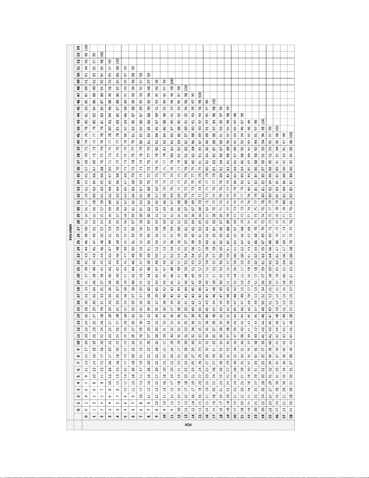
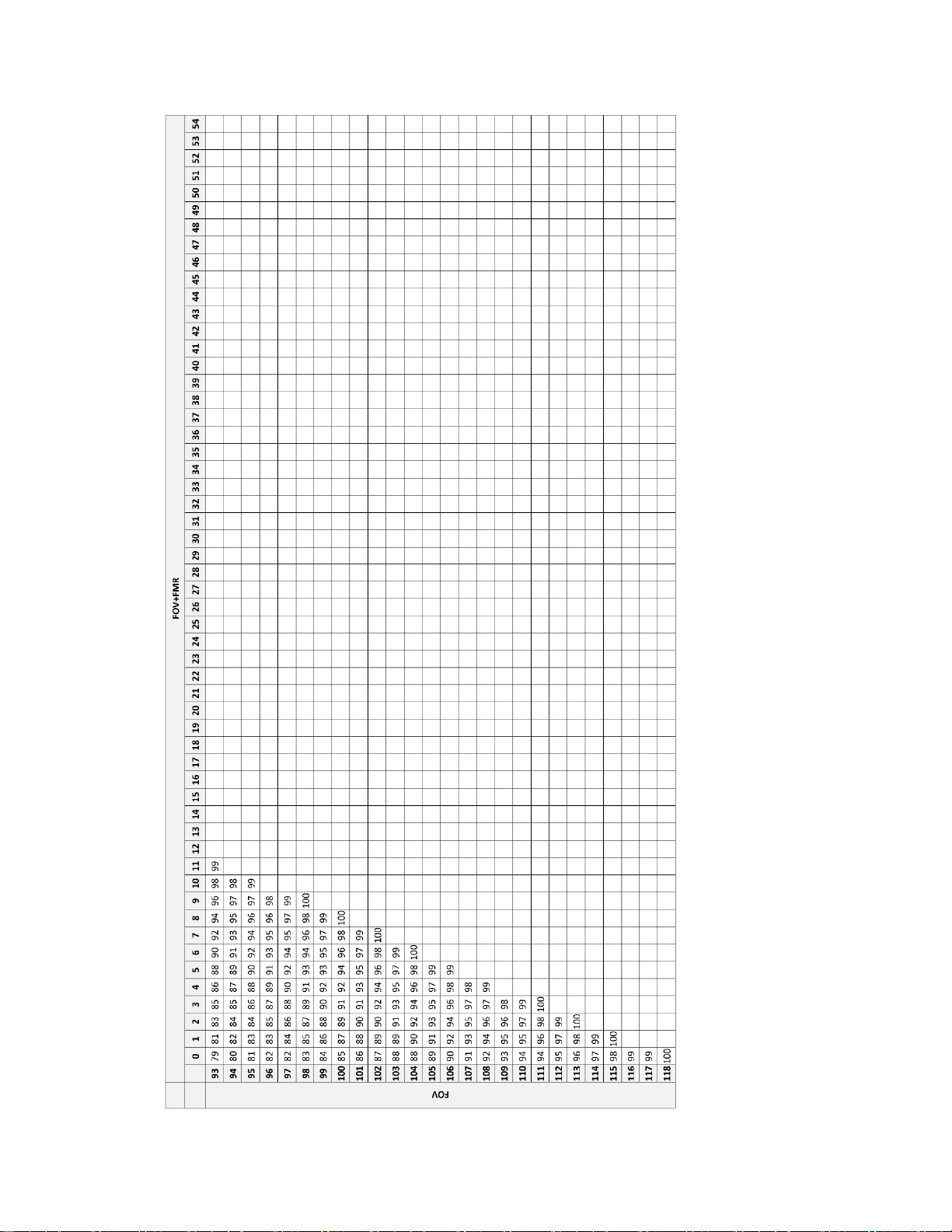
Table 24. Screening Work Completion Look up Table – Integrated Imager, Sequential Modality
Page 27

MAN-05359-001 -001 Rev. 001 page 23 of 32
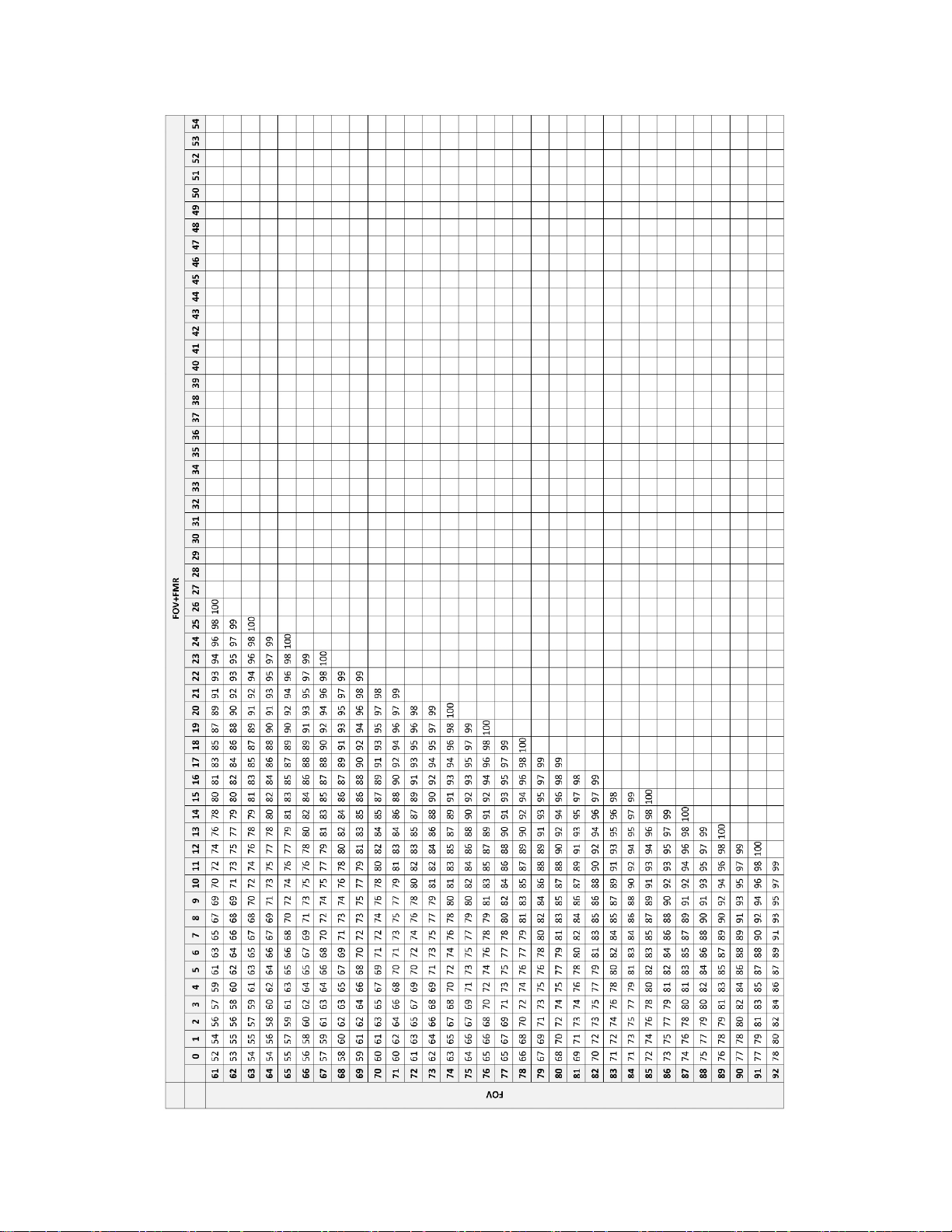
Table 24. Screening Work Completion Look up Table – Integrated Imager, Sequential Modality, continued
Page 28
MAN-05359-001 -001 Rev. 001 page 24 of 32
Table 24. Screening Work Completion Look up Table – Integrated Imager, Sequential Modality, continued
Page 29
MAN-05359-001 -001 Rev. 001 page 25 of 32
Table 24. Screening Work Completion Look up Table – Integrated Imager, Sequential Modality, continued
Page 30
MAN-05359-001 -001 Rev. 001 page 26 of 32
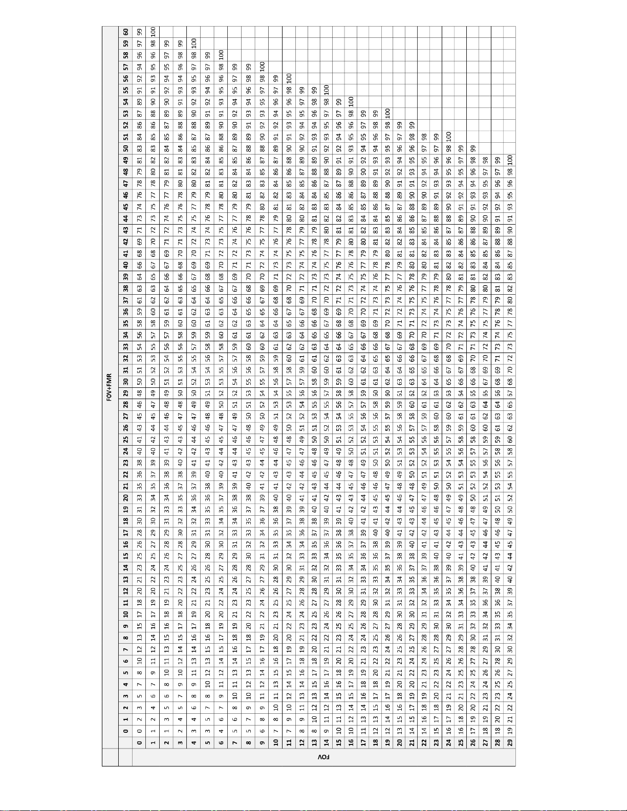
Table 25. Screening Work Completion Look up Table – Integrated Imager, Batched Modality
Page 31

MAN-05359-001 -001 Rev. 001 page 27 of 32
Table 25. Screening Work Completion Look up Table – Integrated Imager, Batched Modality, continued
Page 32

MAN-05359-001 -001 Rev. 001 page 28 of 32
Table 25. Screening Work Completion Look up Table – Integrated Imager, Batched Modality, continued
Page 33

MAN-05359-001 -001 Rev. 001 page 29 of 32
Table 25. Screening Work Completion Look up Table – Integrated Imager, Batched Modality, continued
Page 34

MAN-05359-001 -001 Rev. 001 page 30 of 32
Table 25. Screening Work Completion Look up Table – Integrated Imager, Batched Modality, continued
Page 35

H. Clinical Investigation Conclusions
When ThinPrep Integrated Imager is compared to ThinPrep Imaging System, reviewers achieved
higher sensitivity in all abnormal categories. There was some decrease in specificity.
For ASCUS+ slides, the increase of sensitivity was 3.8% with 95% confidence interval of
2.6% to 5.0% and a decrease of specificity was -1.9% with 95% confidence interval of
-2.8% to -1.0%.
For LSIL+ slides, the increase in sensitivity was 5.8% with 95% confidence interval of
4.1% to 7.5% and a decrease of specificity was -1.9% with a 95% confidence interval of
-2.6 to -1.2%
For HSIL+ the increase in sensitivity was 7.9% with a 95% confidence interval of 4.5% to
11.2% and a decrease in specificity of -1.1% with a 95% confidence interval of -1.6% to
-0.6%.
Considering the technological similarity of the ThinPrep Imaging System and the comparative
clinical study results, it is concluded that the ThinPrep Integrated Imager is similar to the ThinPrep
Imaging System and may be used as replacement for manual review of ThinPrep
prepared on the ThinPrep 2000 System and the ThinPrep 5000 processor for the presence of atypical
cells, cervical neoplasia, including its precursor lesions (Low Grade Squamous Intraepithelial
Lesions, High Grade Squamous Intraepithelial Lesions), and carcinoma as well as all other
cytological criteria as defined by the Bethesda System.
®
Pap Test slides
The screening volume for the CTs when using the Integrated Imager for the imaging and review of
slides is within the Clinical Laboratory Improvement Amendments (CLIA) guidelines for total
number of slides that can be screened in one day.
In order to increase the number of slides that can be reviewed by a cytotechnologist in one day,
slides can be imaged in advance (in batched modality) and then reviewed by the CT in a batch.
The number of slides that a cytotechnologist can scan and review in one day is less on the Integrated
Imager than the ThinPrep Imaging System.
Performance may vary from site to site as a result of differences in patient populations and
reading practices. As a result each laboratory using this device should employ quality
assurance and control systems to ensure proper use and selection of appropriate workload
limits.
For these clinical sites and these study populations, the data from the clinical trial
demonstrate that the use of the ThinPrep Integrated Imager to assist in primary cervical
cancer screening of ThinPrep
®
Pap Test slides for the presence of atypical cells, cervical
neoplasia, including its precursor lesions, and carcinoma as well as all other cytological
criteria as defined by the Bethesda System, is safe and effective for the detection of cervical
abnormalities.
Bibliography
1. Nayar R, Wilbur DC. (eds). The Bethesda System for Reporting Cervical Cytology: Definitions,
Criteria, and Explanatory Notes. 3rd ed. Cham, Switzerland: Springer: 2015
®
2. Hologic, Inc. ThinPrep
number MAN-03938-001.
Imaging System Operation Summary and Clinical Information. Part
MAN-05359-001 -001 Rev. 001 page 31 of 32
Page 36

Hologic, Inc.
250 Campus Drive
Marlborough, MA 01752 USA
1-800-442-9892
www. hologic.com
© 2018 Hologic, Inc. All rights reserved.
AW-17110-001 Rev. 001
4-2018
MAN-05359-001 -001 Rev. 001 page 32 of 32
Page 37

Table of Contents
Table of Contents
Page 38

Table of Contents
Contents
Chapter One
INTRODUCTION
CONTENTS
SECTION A:
SECTION B:
SECTION C:
SECTION D:
SECTION E:
SECTION F:
SECTION G:
Chapter Two
INSTALLATION
SECTION A:
SECTION B:
SECTION C:
SECTION D:
SECTION E:
SECTION F:
SECTION G:
Overview 1.1
The ThinPrep® Imaging and Review Process 1.2
Specimen Preparation 1.5
Integrated Imager Technical Specifications 1.6
Internal Quality Control 1.10
Integrated Imager Hazards 1.11
Disposal 1.15
General 2.1
Action Upon Delivery 2.1
Preparation Prior to Installation 2.1
Moving the Integrated Imager 2.2
Connecting Integrated Imager Components 2.4
Power On the Integrated Imager 2.7
System Settings 2.9
SECTION H:
SECTION I:
SECTION J:
Chapter Three
USER INTERFACE
SECTION A:
SECTION B:
SECTION C:
SECTION D:
SECTION E:
User Preferences 2.9
Storage and Handling - Post Installation 2.9
System Shutdown 2.9
Overview 3.1
Startup 3.3
Administrative Options 3.4
Login 3.30
Main Menu 3.31
ThinPrep® Integrated Imager Operator’s Manual
i
Page 39

CONTENTS
SECTION F:
SECTION G:
SECTION H:
Chapter Four
OPERATION
SECTION A:
SECTION B:
SECTION C:
SECTION D:
SECTION E:
SECTION F:
Chapter Five
MAINTENANCE
SECTION A:
SECTION B:
User Preferences 3.32
Save to USB 3.42
Start 3.45
Overview 4.1
Materials Required Prior to Operation 4.3
Using the Touch Screen and Review Controls 4.4
Slide Imaging 4.7
Slide Review 4.11
Review of Slides Not for Use with
ThinPrep® Imaging 4.21
General Cleaning 5.1
Koehler Alignment 5.2
Chapter Six
TROUBLESHOOTING
SECTION A:
SECTION B:
SECTION C:
SECTION D:
SECTION E:
SECTION F:
Chapter Seven
SERVICE INFORMATION
Chapter Eight
ORDERING INFORMATION
INDEX
Automated Database Backup Failed 6.1
User-Initiated Database Backup Failed 6.2
Invalid Slide ID 6.3
Failed to Read Slide ID 6.3
Slide ID Mismatch While Completing the Review 6.5
Error Handling 6.6
7.1
8.1
ii
ThinPrep® Integrated Imager Operator’s Manual
Page 40

1. Introduction
1. Introduction
Page 41

1
INTRODUCTION
SECTION
A
Chapter One
Introduction
OVERVIEW
The ThinPrep® Integrated Imager is an automated cytology review microscope with ThinPrep slide
imaging functionality. It is specifically designed to image and review ThinPrep Pap Test microscope
slides on-demand. It also has the ability to act as a conventional microscope when not used in
conjunction with ThinPrep imaging.
The Integrated Imager consists of:
The
Microscope
hand controls and adjustable touch screen user interface.
- a customized microscope with imaging camera, slide ID reader, automated stage,
Controller
Computer
, which controls the electromechanical and imaging subsystems.
with touch screen display that hosts the system application and database.
Figure 1-1 Integrated Imager
ThinPrep® Integrated Imager Operator’s Manual
1.1
Page 42

INTRODUCTION
1
SECTION
B
THE THINPREP IMAGING AND REVIEW PROCESS
Imaging
A prepared ThinPrep® Pap Test microscope slide is loaded onto the stage of the device. A slide
identification camera reads the slide label ID and compares it against slide IDs already in the
computer database.
• If the slide ID is new, the slide is imaged.
• If the slide ID is already in the database, the software prompts for the slide to be reviewed.
• If the slide has already been reviewed, it may be reviewed again.
To ensure that the focus and light requirements for imaging are correct and will not be interrupted
during the scan, the system disables any manual stage, focus and illumination controls. The
instrument uses an LED light source to illuminate the optical path to image. The entire cell spot is
imaged in approximately 90
integrated optical density. The coordinates of 22 of those objects are recorded and, with the slide ID,
are stored in the system database. (See
seconds. The system identifies objects of interest on the slide based on
Figure 1-3.)
Review
The device next behaves as an automated microscope, presenting the 22 fields of interest to the CT
(cytotechnologist) and providing additional slide review when suspect cells are found. This is
termed ‘Auto Locate.’ Manual control of the stage, focus and illumination is returned for the CT’s
use. The instrument uses a white LED light source for illumination for slide review. The CT interacts
with the review controls both via substage hand controls and by the touch screen.
Each field of view is presented to the CT at 10X magnification. The nosepiece also has 4X and 40X
objectives, which the CT can switch manually. Before the next field of view can be presented, the
Integrated Imager senses if the 10X objective is engaged in the light path. If not, the system prompts
the CT to return the magnification to 10X. All 22 fields of view will be presented to the CT at 10X
magnification.
Note:
During slide review, the CT has the option to electronically mark an area for subsequent review and/
or physical marking. One or more electronic marks enforces a review of the entire cell spot. This is
termed ‘Auto Scan.’
During Auto Scan review, the CT may add or delete electronic marks. Physical marking of these
areas on the slide coverslip with a pen is done manually by the CT.
The CT has the option to control the position of the stage manually, which provides complete
freedom to move any portion of the cell spot into the field of view for examination.
The object of interest is typically placed in the center of the field of view, however the CT
must screen the entire field of each of the 22 fields of view presented.
1.2
ThinPrep® Integrated Imager Operator’s Manual
Page 43

1
Cytotechnologist Actions
Integrated Imager Actions
Ready to accept next slide
Image slide
CT controls stage
CT controls stage
Ready to remove slide
Pick next slide from tray, insert
Write up review of previous slide
Auto Locate and slide review
Scan entire cell spot and
additional slide review
Remove slide and place in tray
4. Remove
3a. Review
(abnormal only)
3. Review slide
2. Image slide
1. Insert slide
Step
INTRODUCTION
Figure 1-2 Integrated Imager Workflow
ThinPrep® Integrated Imager Operator’s Manual
1.3
Page 44

1
A prepared ThinPrep®
Pap Test slide is loaded
onto the Integrated
Imager stage.
The cell spot is imaged.
Slide review by the
cytotechnologist.
Normal slide
The slide ID is scanned.
• If an ID is new to the database
the slide will be imaged.
• An ID already in the database
prompts the user to review the
slide.
The slide imaging system scans the
entire cell spot. The system identifies
objects of interest found on the slide.
The coordinates of 22 objects of
interest with the highest integrated
optical density will be stored in the
computer’s database.
During Auto Locate the system presents the 22 selected fields of view in
geographic order to the cytotechnologist.
Suspect cells may be electronically
marked by the CT and a review of
the entire cell spot is enforced. The
slide is manually marked by the CT.
At completion, the slide data is
updated with the location of electronic marked areas as well as information on the review session.
Abnormal slides are reviewed by a
cytopathologist for interpretation
and diagnosis.
INTRODUCTION
1.4
ThinPrep® Integrated Imager Operator’s Manual
Figure 1-3 ThinPrep Imaging Process
Page 45

1
INTRODUCTION
SECTION
C
SPECIMEN PREPARATION
Specimens for the ThinPrep® Pap Test cytology slide are collected by a clinician, then immersed and
®
rinsed in a PreservCyt
laboratory equipped with a ThinPrep Processor. After being processed, the slides are stained with
ThinPrep Stain and coverslipped with one of the following:
• glass coverslips, #1 thickness, 24 mm wide, 40–50 mm long
• Sakura Tissue-Tek® SCA™ coverslipped film, 45 mm long, not covering any portion of the
frosted area (Sakura part number 4770)
• Klinipath KP-Tape, 45 mm long, not covering any portion of the frosted area (Klinipath part
number 3020)
Please refer to the operator’s manuals of these instruments for more information regarding
preparation and processing of ThinPrep slides.
Solution sample vial. The sample is then capped, labeled, and sent to a
Special Precautions
There are conditions that might result in a slide not being successfully imaged. Some conditions may
be prevented or corrected by following these guidelines.
• ThinPrep microscope slides with fiducial marks are being used. The fiducial marks should not
be scratched or marred.
• The coverslip media is dry (wet media could cause equipment malfunction).
• The slides are clean (no fingerprints, dust, debris, bubbles). Handle the slides by the edges.
• The coverslip and the label do not extend beyond the surface of the slide.
• The slide is labeled in one of the formats supported by the ThinPrep Integrated Imager.
Specimen Integrity
PreservCyt Solution with cytologic sample intended for ThinPrep Pap testing must be stored
between 15°C(59°F) and 30°C (86°F) and tested within 6 weeks of collection.
Slides processed by a ThinPrep Processor should be stained within 5 days.
Stained slides should be imaged by the Integrated Imager in a timely manner, according to normal
laboratory practices. Imaging performance has not been assessed beyond 4 months.
Specimen sample - the use of lubricants (e.g., KY Jelly) should be minimized prior to specimen
collection. Lubricants can adhere to the filter membrane and may cause poor cell transfer to the slide.
Stain - do not substitute solutions for the ThinPrep Stain solutions. Follow the stain protocols exactly
as they are written. Refer to the ThinPrep Stain User’s Manual.
Specimen Handling
The ThinPrep slides are stored, transported and handled the same as conventional cytology slides.
Please refer to your laboratory guidelines for specimen handling.
ThinPrep® Integrated Imager Operator’s Manual
1.5
Page 46

INTRODUCTION
1
SECTION
D
17
1. Eyepieces
2. Binocular tube
3. Revolving nosepiece (4X, 10X,
40X, plus position sensor)
4. Motorized stage
5. Condenser (under stage)
6. Collector
7. Coarse/fine focus knob (on left
side of microscope)
8. Light intensity adjustment knob
9. X,Y axis stage control knobs
(stage control)
10. Microscope power switch
(on back left of microscope with
black side panel)
11. Allen screwdriver
(near the controller on the back of
the microscope with the black
side panel)
12. Computer
13. Touch screen interface
14. Computer power switch
15. Controller
16. Review control
17.
Note:
The “SET” button is not
used.
The “LIM” button is also
not used and will
illuminate, with no effect, if
pushed.
Revolving nosepiece
4X objective (red stripe)
10X objective (yellow stripe)
40X objective (blue stripe)
10X objective position sensor
9
8
7
3
6
16
INTEGRATED IMAGER TECHNICAL SPECIFICATIONS
Overview of Components
1
2
4
5
10
13
15
11
14
12
1.6
ThinPrep® Integrated Imager Operator’s Manual
Figure 1-4 Integrated Imager Components
Page 47

1
Dimensions
457 mm
18 in.
609 mm
24 in.
711 mm
28 in.
INTRODUCTION
Figure 1-5 Integrated Imager Dimensions
ThinPrep® Integrated Imager Operator’s Manual
1.7
Page 48

INTRODUCTION
1
Slide Accession ID
(OCR format shown)
Fiducial mark
Fiducial mark
Frosted portion of the slide
Cell spot - contains patient
sample cells
Fiducial mark
ThinPrep® Microscope Slide for Use with the Imaging System
The ThinPrep microscope slide is used by the ThinPrep Processor in preparing the patient slide. The
slide utilizes fiducial marks, or fixed reference points, which are permanently printed features on the
slide that are used to register the slide position on the stage. A coordinate system is based on the
fiducial marks, for locating objects of interest on the cell spot.
Weight
The Integrated Imager system - including the microscope, controller, computer and all cabling
weighs approximately 32
Environmental
Operating temperature range
16°C to 32°C (60°F to 90°F)
Non-operating temperature range
-29°C to 50°C (-20°F to 122°F)
Operating humidity range
20% to 80% relative humidity, non-condensing
Non-operating humidity range
15% to 95% relative humidity, non-condensing
Pollution Degree II, in accordance with IEC 61010-1
Category II. The Integrated Imager is for indoor use only in an office or a clean laboratory
environment.
Altitude
0 meters (sea level) to 2000 meters
Figure 1-6 ThinPrep Microscope Slide
kg (70 lbs.).
1.8
ThinPrep® Integrated Imager Operator’s Manual
Page 49

1
INTRODUCTION
Atmospheric pressure
1100 millibar to 500 millibar
Sound levels
Maximum A-weighted sound pressure level at the operator’s position and at a bystander’s position
dBA.
is 66.2
Power
Voltage
100-120V~/220-240V~ single phase, 50–60 Hz
Power
Less than 150 Watts (51 2 Btu/hour) for the microscope and controller, not including the
computer
Power cables
Maximum length must be less than 3 m (9.8 ft.).
Fusing
Two 3.15A, 250 VAC, time delay, low break capacity (instrument)
Note:
Fuses are not user-accessible and are not intended to be changed by users. Contact Technical
Support if the instrument does not operate. Do not remove any covers on the components.
Connections to external circuits
The external connections on the PC are PELV (Protected Extra Low Voltage) as defined by IEC
61140. Outputs of other devices connected to the PC should also be PELV or SELV (Safety
Extra Low Voltage). Only devices approved for safety by an appropriate agency should be
connected to the PC.
Note:
The computer manufacturer provides documentation for the PC. Refer to that for technical
specifications. Do not discard.
Safety, EMI and EMC Standards
The Integrated Imager has been tested and certified by a U.S. nationally recognized testing
Laboratory (NRTL) to comply with current Safety, Electro-Magnetic Interference (EMI) and ElectroMagnetic Compatibility (EMC) standards. Refer to the model/rating label, located on the rear of the
controller, to see the safety certification markings. This equipment meets the IEC 61010-2-101
particular safety requirements for IVD equipment.
This equipment meets the emission and immunity requirements of IEC 61326-2-6. This equipment
has been tested and found to comply to CISPR 11 Class A emission limits.
In a domestic environment it may cause radio interference, in which case, measures to mitigate the
interference may be necessary. The electromagnetic environment should be evaluated prior to
operation of the equipment. Do not use this device in close proximity to sources of strong
electromagnetic radiation (e.g., unshielded RF sources), as these may interfere with the proper
operation.
ThinPrep® Integrated Imager Operator’s Manual
1.9
Page 50

INTRODUCTION
1
SECTION
E
This product is
This product contains a device classified per EN 60825-1 as a Class I LED product.
in vitro
diagnostic (IVD) medical equipment.
INTERNAL QUALITY CONTROL
Power On Self Test (POST)
At the time the Integrated Imager is powered on, the system goes through a self-diagnostic test. All
electrical, mechanical and software/communication systems are tested to confirm each performs
properly. The operator is alerted to any malfunction via a message on the user interface. If the system
does not function or there are persistent errors, contact Hologic
Service Information).
Post Scan Functional Checks
At the completion of slide imaging and slide review, the instrument will do functional checks to
ensure integrity of the data gathered during imaging or review. The operator is alerted to any
malfunction via a message on the user interface. If the system does not function or there are
persistent errors, contact Hologic
Technical Support(refer to Chapter 7, Service Information).
Technical Support(refer to Chapter 7,
1.10
ThinPrep® Integrated Imager Operator’s Manual
Page 51

1
INTRODUCTION
SECTION
F
INTEGRATED IMAGER HAZARDS
The Integrated Imager is intended to be operated in the manner specified in this manual. Be sure to
review and understand the information listed below in order to avoid harm to operators and/or
damage to the instrument.
Do not operate the Integrated Imager with the dust cover on it.
If this equipment is used in a manner not specified by the manufacturer, then the protection provided
by the equipment may be impaired.
Warnings, Cautions and Notes
The terms
•A
or death.
WARNING, CAUTION
WARNING
advises against certain actions or situations that could result in personal injury
and
Note
have specific meanings in this manual.
•A
CAUTION
inaccurate data or invalidate a procedure, although personal injury is unlikely.
•A
Note
provides useful information within the context of the instructions being provided.
advises against actions or situations that could damage equipment, produce
ThinPrep® Integrated Imager Operator’s Manual
1.11
Page 52

INTRODUCTION
1
Symbols Used on the Instrument
The following symbols are used on this instrument:
Symbol Title Description Standard information
Caution Indicates the need for the user to
consult the instructions for use for
important cautionary information
such as warnings and precautions
that cannot, for a variety of
reasons, be presented on the
medical device itself.
In vitro diagnostic
medical device
Authorized
Representative in
the European
Community
Serial number Indicates the manufacturer’s serial
Indicates a medical device that is
intended to used as an in vitro
diagnostic medical device
Indicates the Authorized
Representative in the European
Community
number so that a specific medical
device can be identified
ISO 15223-1 Medical
devices—Symbols to be used
with medical device labeling
and information to be supplied,
Section 5.4.4
ISO 15223-1 Medical
devices—Symbols to be used
with medical device labeling
and information to be supplied,
Section 5.5.1
ISO 15223-1 Medical
devices—Symbols to be used
with medical device labeling
and information to be supplied,
Section 5.1.2
ISO 15223-1 Medical
devices—Symbols to be used
with medical device labeling
and information to be supplied,
Section 5.1.7
1.12
Catalogue
Number
Manufacturer Indicates the medical device
Date of
manufacture
ThinPrep® Integrated Imager Operator’s Manual
Indicates the manufacturer's
catalogue number so that the
medical device can be identified
manufacturer, as de fined in the EU
Directives 90/385/EEC, 93/42/EEC
and 98/79/EC
Indicates the date when the
medical device was manufactured.
ISO 15223-1 Medical
devices—Symbols to be used
with medical device labeling
and information to be supplied,
Section 5.1.6
ISO 15223-1 Medical
devices—Symbols to be used
with medical device labeling
and information to be supplied,
Section 5.1.1
ISO 15223-1 Medical
devices—Symbols to be used
with medical device labeling
and information to be supplied,
Section 5.1.3
Page 53

1
INTRODUCTION
1
2
3
4
5
6
Symbol Title Description Standard information
Fuse To identify fuse boxes or their loca-
tion.
And this instrument uses the following markings:
Waste Electrical and Electronic Equipment
Do not dispose in municipal waste
Contact Hologic for disposal of the instrument
On (Power switch on the microscope)
Off (Power switch on the microscope)
IEC 60417 Graphical symbols
for use on equipment, symbol
5016
Lamp intensity adjustment
Stand by power (computer)
USB port icon (computer)
Ethernet port icon (computer)
Monitor display (computer)
ThinPrep® Integrated Imager Operator’s Manual
1.13
Page 54

INTRODUCTION
1
Instrument
part number label
Instrument
serial number label
Model/rating label
(includes these marks)
Rear of Instrument (PC removed for clarity.)
PC serial number on top
(not shown)
USB port
Power
Ethernet port
USB port (5)
Front and Rear of Computer
(
Note:
The number and exact location of ports may be different, depending on the PC model you have.)
Location of Labels
Figure 1-7 Location of Labels
1.14
ThinPrep® Integrated Imager Operator’s Manual
Page 55

1
INTRODUCTION
SECTION
G
Warnings Used in this Manual
WARNING: Service Installation Only. This instrument is to be installed by trained Hologic
personnel only.
WARNING: Moving Parts. The instrument contains moving parts. Keep hands, loose clothing,
jewelry, etc., clear.
WARNING: Grounded Outlet. To ensure safe operation of the instruments, use a three-wire
grounded outlet.
WARNING: Glass. The instrument uses microscope slides, which have sharp edges. In addition,
the slides may be broken in their storage packaging or on the instrument. Use caution when
handling glass slides and when cleaning the instrument.
DISPOSAL
Disposal of consumables
Disposal of instrument fuses. No special instructions, used fuses may be disposed of in your
laboratory refuse.
Broken glass. Dispose of in a sharps container.
Disposal of the device
Please contact Hologic Service (refer to Chapter 7, Service Information).
Do not dispose in municipal waste.
Hologic, Inc.
250 Campus Drive
Marlborough, MA 01752 USA
Tel: 1-800-442-9892
1-508-263-2900
Fax: 1-508-229-2795
Web: www.hologic.com
ThinPrep® Integrated Imager Operator’s Manual
1.15
Page 56

INTRODUCTION
1
This page intentionally left blank.
1.16
ThinPrep® Integrated Imager Operator’s Manual
Page 57

2. Installation
2. Installation
Page 58

2
Chapter Two
SECTION
A
SECTION
B
SECTION
C
Installation
INSTALLATION
WARNING:
Service Installation Only
GENERAL
The ThinPrep® Integrated Imager must be installed by Hologic service personnel. When
installation is complete, Hologic personnel train the operator(s), using the operator’s manual as
the training guide.
ACTION UPON DELIVERY
Remove and read the
carton.
Inspect the packing cartons for damage. Report any damage immediately to the shipper and/or
Hologic
Leave the instrument in the packing cartons for Hologic service installation.
Store the instrument in a suitable environment until installation (cool, dry, vibration-free area).
Technical Support as soon as possible. (Refer to Chapter 7, Service Information.)
Operating Instructions Prior to Installation
sheet attached to the packing
Note:
The computer manufacturer provides documentation for the PC. Refer to that for technical
specifications. Do not discard.
PREPARATION PRIOR TO INSTALLATION
Pre-Installation Site Assessment
A pre-installation site assessment is performed by Hologic service personnel. Be sure to have
prepared any and all site configuration requirements as instructed by the service personnel.
The Integrated Imager will require two outlets to power the instrument. Make sure there is
adequate electrical supply within 2 meters of the instrument. It must be plugged into a three-prong
grounded outlet. Disconnection from the power supply source is by removal of the power cord.
Note:
Do not position the instrument so that it is difficult to disconnect the power cords.
ThinPrep® Integrated Imager Operator’s Manual
2.1
Page 59

INSTALLATION
2
SECTION
D
Location
The Integrated Imager ‘foot print’ is approximately 76.2 cm x 61 cm, and <76.2 cm high (30 in. x
24
in., and < 30 in. high). Make sure there is adequate desk space for placing slide flats or
containers. (See
or bench can support the weight.
Figure 2-1.) The instrument is approximately 32 kg (70 pounds). Be sure the table
CAUTION:
disconnecting cabling, do not place cabling near foot traffic.
The Integrated Imager is sensitive to vibrations. It should be placed on a flat, sturdy surface away
from any vibrating equipment.
If your system is configured with the computer located separately from the microscope, be
sure it is in a dust-free area, with reasonable access to the power switch.
Route connections carefully to avoid pinching the cables. To avoid tripping over, or
Figure 2-1 A Typical Integrated Imager Configuration
MOVING THE INTEGRATED IMAGER
The Integrated Imager is a precision instrument and should be handled with care. If the system
must be moved, the controller and computer PC must be disconnected from one another,
moved separately and reconnected at the new location.
2.2
ThinPrep® Integrated Imager Operator’s Manual
Page 60

2
INSTALLATION
Computer AC power cord
1 (USB cable)
2 (USB cable)
3 (USB cable)
VGA (for touch screen)
Firewire (for internal camera)
4 (USB cable)
The microscope and controller are mechanically and electronically connected and should
NOT be separated. The cabling between the controller and the computer may be disconnected
and reconnected, see
Before disconnecting any of the components, be sure to observe how they are originally connected.
See
Figure 2-2.
Figure 2-2.
Note:
The computer may be set up to face either side, or with the use of the extension cable set, it
can be placed further away from the microscope and controller. Your final configuration may
look slightly different than
same.
Figure 2-2 Integrated Imager Interconnections
Figure 2-2. The cable connections to the computer ports remain the
ThinPrep® Integrated Imager Operator’s Manual
2.3
Page 61

INSTALLATION
2
SECTION
E
The microscope should be grasped and lifted by the frame housing. Grasp the frame behind
the nosepiece turret as shown in
Figure 2-3.
CAUTION:
CAUTION:
microscope and may render it inoperable.
The instrument weighs 70 lbs. (32 kg) and should be moved by at least two people.
Lifting the instrument by the motorized stage or top cover will cause damage to the
Figure 2-3 Moving the Integrated Imager
CONNECTING INTEGRATED IMAGER COMPONENTS
The Integrated Imager components must be fully assembled before turning on the power and
using the instrument. Hologic service personnel will assemble the instrument:
• Controller
• Computer
• Microscope
• Assemble spacers, trinocular head (optional telescoping head or riser)
• Eyepieces
• Objectives
• User interface touch screen and mounting rail
Controller
Computer
2.4
, which controls the electromechanical and imaging subsystems.
that hosts the system application and database.
ThinPrep® Integrated Imager Operator’s Manual
Page 62

2
INSTALLATION
MAGNET
Open
40X
10X
4X
MAGNET
10X
4X
40X
20X
Front
Front
Magnetic 10X
position sensor.
Do not move.
Standard Configuration for
4X, 10X and 40X
Optional Configuration for
4X, 10X, 20X and 40X
The
Microscope
stage, stage controls and touch screen interface.
The
trinocular head
camera. The light path and camera focus have been optimized by placement of spacers in the
assembly of the optical components. Do not add or remove spacers or risers.
- a customized microscope with imaging camera, slide ID camera, automated
- a tilting binocular observation tube and a fixed, straight tube for the imaging
If an optional
supplies.
One ocular has a diopter adjustment ring to provide common focus capability.
If the optional riser is being used, do not use it in conjunction with the telescoping head. Use one
or the other, but not both.
CAUTION:
pieces or objectives.
Eyepieces
Objectives
They are specifically compatible with the supplied eyepieces and the camera for the imaging
system. They should not be substituted with any other objectives.
The other object in the nosepiece is the magnetic 10X position sensor. It must not be removed.
An optional 20X objective is available. (Refer to Chapter 8, Ordering Information.) It can be
installed by the operator. If the 20X objective is installed, the objectives should be positioned as
shown in
telescoping head
Only use Hologic-supplied eyepieces and objective lenses. DO NOT substitute eye-
- 10X magnification with a field size of 22 mm.
- 4X, 10X and 40X objectives are mounted on the revolving nosepiece at production.
Figure 2-4.
is being used, be sure to use the specific riser that Hologic
Figure 2-4 Positions of Objectives in the Nosepiece
User interface
the screen up or down along the mounting rail. The tilt and rotational angle of the screen may be
adjusted by loosening the adjustment knobs, changing the tilt and rotation, and then tightening
each knob.
touch screen
and mounting rail - the touch screen height can be adjusted by moving
ThinPrep® Integrated Imager Operator’s Manual
2.5
Page 63

INSTALLATION
2
Y -Ax is tension adjustment sleeve
Y-Axis stage control
X-Axis tension
adjustment sleeve
X-Axis stage control
Allen screw
Adjustment slot
Rotate review
control
CAUTION:
Filters
the imaging is intended, do
objectives.Adjusting the X,Y Axis Stage Control Knob Tension and Height
The X- and Y-axis stage control knob tension and height may be adjusted to suit the operator’s
preference. See
- To ensure that the imaging camera images the cell spot at the correct gray scale for which
Do not use filters on the collector or in the objectives.
not place filters
Figure 2-5.
in the illumination path on the collector or in the
The Y-axis is adjusted by accessing the adjustment sleeve above the knob. To adjust the X-axis, pull
the X- and Y-axis stage control knobs apart to reveal the adjustment sleeve of the X-axis stage
control. To loosen the tension, turn the adjustment sleeves counterclockwise. For a tighter tension,
turn the sleeve clockwise for either control.
To adjust the height, the X- and Y-axis stage control knobs may be slid downward or upward on
the vertical axis of the assembly shaft.
Leave a small gap between the X- and Y-axis stage control knobs, to ensure there is no interference
in the movement of either knob.
Adjust the Review Control Position
The Review Control may be positioned closer or further from the stage controls via an adjustment
slot. See
Using the Allen screwdriver that comes with the Integrated Imager (see Figure 1-4), loosen but do
not remove the Allen screw that holds the review control to the mounting bracket.
2.6
Figure 2-5 Adjust Substage Controls
Figure 2-5.
ThinPrep® Integrated Imager Operator’s Manual
Page 64

2
INSTALLATION
SECTION
F
2
Computer power
switch
1
Microscope power switch
Slide the review control along the slot to where it feels most comfortable for your hand position.
The review control may also be rotationally adjusted, if desired. When finished, tighten the Allen
screw with the screwdriver.
POWER ON THE INTEGRATED IMAGER
WARNING:
Do not power on or operate if equipment has been damaged.
To ensure safe operation of the instrument use a three-wire grounded outlet.
Note:
It is important to apply power to the Integrated Imager system in the correct order.
1. First power on the microscope.
2. Then power on the computer.
All power cords must be plugged into a grounded outlet. Disconnection from the power supply source is by removal of the power cord.
Grounded Outlet
Figure 2-6 Power Switches
The power switch for the Integrated Imager is located on the back left of the microscope. Press the
switch to the on position.
ThinPrep® Integrated Imager Operator’s Manual
2.7
Page 65

INSTALLATION
2
Any status
messages are
displayed here.
System software version is
displayed
here.
Then press the power button on the computer. Allow the instrument to initialize. While the
instrument boots up and does self checks, a splash screen is displayed,
during boot up are displayed on the lower left of the screen (For example, doing self test, auto backup
in process, etc.) The system software version is displayed on the lower right of the screen.
Figure 2-7. Status messages
WARNING:
The instrument is ready for use when the application main screen is displayed (Figure 2-8).
Moving Parts
Figure 2-7 Integrated Imager Startup Screen
2.8
Figure 2-8 Application Main Screen
ThinPrep® Integrated Imager Operator’s Manual
Page 66

2
INSTALLATION
SECTION
G
SECTION
H
SECTION
I
SECTION
J
Shut Down
button
SYSTEM SETTINGS
Refer to User Interface chapter, “System Settings” on page 3.8.
USER PREFERENCES
Refer to User Interface chapter, “USER PREFERENCES” on page 3.32.
STORAGE AND HANDLING - POST INSTALLATION
The Integrated Imager may be stored in the location where it was installed. When it is not in use,
the power should be turned off. Cover the instrument with the provided microscope dust cover.
SYSTEM SHUTDOWN
Normal Shutdown
Figure 2-9 Shutdown
ThinPrep® Integrated Imager Operator’s Manual
2.9
Page 67

INSTALLATION
2
It is important to shut down the system in the correct order. To shut down the Integrated Imager:
1. Log out if you haven’t already.
2. From the startup screen, press the
Shut Down
button in the upper right corner.
Figure 2-10 Confirm Shutdown
3. A confirmation prompt is displayed. (See Figure 2-10.)
Press the No button to cancel shutdown and return to the main screen.
4. Press the
the computer.
5. Turn off the power switch on the instrument. (See Figure 2-6.)
Extended Shutdown
If the instrument is to be shut down for an extended amount of time or be taken out of service, shut
down as described in Normal Shutdown. Remove any slides that may be on the stage. Completely
remove power by unplugging the controller power cord and the computer cord from the power
outlet. Cover the instrument with the provided dust cover.
Yes
button to shut down the system. This will shut down the application and turn off
2.10
ThinPrep® Integrated Imager Operator’s Manual
Page 68

3. User Interface
3. User Interface
Page 69

3
USER INTERFACE
SECTION
A
SECTION
A
Password
Protected
Database Backup
User Accounts
System Settings
Reports and Logs
Power On
Login
Admin
Options
Service
Manual
Review
Optionally
Password
Protected
Start
User
Preferences
Image Slide
Review Slide
Direction
Overlap
Autoscan Type
Autolocate Speed
Sound
Mark Indicator
Read
Slide ID
Password Settings
Chapter Three
User Interface
OVERVIEW
The ThinPrep® Integrated Imager images prepared ThinPrep Pap Test cervical cytology microscope
slides. The slides are reviewed by a cytotechnologist. The instrument may also be used as a
conventional microscope, for viewing slides not associated with the ThinPrep imaging process.
The Integrated Imager enables the user to administer certain functions, such as user preferences,
system settings and database backup. The user interacts with the instrument via a touch screen
graphic interface.
Refer to Figure 3-1 for an overview of the workflow options.
Figure 3-1 Overview of Integrated Imager Menu
ThinPrep® Integrated Imager Operator’s Manual
3.1
Page 70

USER INTERFACE
3
This chapter introduces the user interface modules of the Integrated Imager and describes the usage
of each. It is recommended that users acquaint themselves with the material in this chapter before
operating the instrument.
The content found in this chapter:
STARTUP . . . . . . . . . . . . . . . . . . . . . . . . . . . . . . . . . . . . . . . . . . . . . . . . . . 3.3
ADMINISTRATIVE OPTIONS . . . . . . . . . . . . . . . . . . . . . . . . . . . . . . . . 3.4
• User Accounts . . . . . . . . . . . . . . . . . . . . . . . . . . . . . . . . . . . . . . . . . . .3.4
• System Settings . . . . . . . . . . . . . . . . . . . . . . . . . . . . . . . . . . . . . . . . . . 3.8
Date
Time
Lab Name
Instrument Name
Label Format
Language
• Reports and Logs . . . . . . . . . . . . . . . . . . . . . . . . . . . . . . . . . . . . . . . . 3.17
• Database Backup . . . . . . . . . . . . . . . . . . . . . . . . . . . . . . . . . . . . . . . . 3.24
• Password Settings. . . . . . . . . . . . . . . . . . . . . . . . . . . . . . . . . . . . . . . . 3.26
LOGIN . . . . . . . . . . . . . . . . . . . . . . . . . . . . . . . . . . . . . . . . . . . . . . . . . . . .3.30
MAIN MENU . . . . . . . . . . . . . . . . . . . . . . . . . . . . . . . . . . . . . . . . . . . . . . 3.31
USER PREFERENCES . . . . . . . . . . . . . . . . . . . . . . . . . . . . . . . . . . . . . . .3.32
• Scan Direction . . . . . . . . . . . . . . . . . . . . . . . . . . . . . . . . . . . . . . . . . . . 3.32
• Scan Overlap . . . . . . . . . . . . . . . . . . . . . . . . . . . . . . . . . . . . . . . . . . . .3.33
• Scan Type . . . . . . . . . . . . . . . . . . . . . . . . . . . . . . . . . . . . . . . . . . . . . . . 3.33
• Speed . . . . . . . . . . . . . . . . . . . . . . . . . . . . . . . . . . . . . . . . . . . . . . . . . . 3.38
• Sound . . . . . . . . . . . . . . . . . . . . . . . . . . . . . . . . . . . . . . . . . . . . . . . . . . 3.40
• Mark Indicator . . . . . . . . . . . . . . . . . . . . . . . . . . . . . . . . . . . . . . . . . . 3.41
SAVE TO USB . . . . . . . . . . . . . . . . . . . . . . . . . . . . . . . . . . . . . . . . . . . . . . 3.42
START. . . . . . . . . . . . . . . . . . . . . . . . . . . . . . . . . . . . . . . . . . . . . . . . . . . . . 3.45
3.2
ThinPrep® Integrated Imager Operator’s Manual
Page 71

3
STARTUP
SECTION
B
USER INTERFACE
Figure 3-2 Startup Display
When the Integrated Imager is powered on and ready for use, the screen display will appear as it
does in
The options available from this interface are:
Note:
Figure 3-2.
•
Admin Options
optional password setting can be applied to access this area. Refer to
OPTIONS” on page 3.4.
•
Service
•
Login
tions. Refer to “LOGIN” on page 3.30.
•
Shut Down
on page 2.9.
•
Manual Slide Review
microscope. The stage is maneuvered by the stage control knobs. No data is retrieved or trans
mitted to the database.
The Integrated Imager must be powered on to manually review slides. The light source, stage
and X, Y axis stage control knobs are powered by the system controller.
- This is a password-protected module for use by Hologic service personnel only.
- Enter a user ID to access the system for ThinPrep Imaging and Slide Review func-
- System settings and user accounts are maintained from this module. An
“ADMINISTRATIVE
- This is how to turn off the Integrated Imager. Refer to “SYSTEM SHUTDOWN”
- Without logging in, the user may look at slides as on a conventional
-
ThinPrep® Integrated Imager Operator’s Manual
3.3
Page 72

USER INTERFACE
3
SECTION
C
ADMINISTRATIVE OPTIONS
Figure 3-3 Administrative Options Screen
The Administrative Options screen allows set up and customizing of the Integrated Imager. From
this menu the Operator may:
• Administer User Accounts
• Apply or change System Settings
• View system logs or save them to a USB key
• Backup the system database to a CD ROM or USB key
• Apply or remove password access to the administrative options interface.
User Accounts
Figure 3-4 User Accounts Button
The User Accounts interface is used to create and retire User IDs. A User ID is required when a
person presses the
Log In
button to initiate a session with the Integrated Imager.
Information associated with a User ID becomes part of the slide data record when a slide is imaged
and when a slide is reviewed, using the Integrated Imager.
3.4
ThinPrep® Integrated Imager Operator’s Manual
Page 73

3
USER INTERFACE
List of user accounts,
with user name and ID
Add Account
, to add
an account to the list
Done
button, to return
to the Admin Options
screen
Save to USB
key
Enter a 3-digit
ID number
(from 100 to
998) using
the keypad.
Note:
When the User Accounts screen is displayed, a list of all accounts that have been created is displayed:
the user’s name and the login ID number. (Refer to
To maintain the integrity of the slide data records, User IDs are not to be reissued. Only
unique IDs may be assigned.
Figure 3-5.)
Figure 3-5 User Accounts Display
Add account
To add a new User Account, press the
Enter a unique three-digit number and touch the
already assigned, an “invalid ID” message will appear and a new ID number must be entered.
Add Account
Figure 3-6 Add User Account Screen
button. A keypad display appears (Figure 3-6).
Continue
ThinPrep® Integrated Imager Operator’s Manual
button. If the desired ID number is
3.5
Page 74

USER INTERFACE
3
If the ID number is not assigned, the next display is a keyboard for entering the name of the User
Account. See
Figure 3-7.
Note:
Note:
Press the letter buttons to enter a first name. To create a capital letter, press the
press the letter. With the next letter, the system reverts to lowercase. Use the
and the
User ID numbers must be between the range of 100 to 998. Numbers beginning with a zero
will cause errors.
User ID 999 is reserved for Hologic service personnel. Do not use this ID.
Figure 3-7 Enter User Name Screen
Space
Delete
button to remove entered letters.
Shift
button and then
button for a space
Press the
button when finished to return to the User Accounts main screen. The new account will be listed. See
Figure 3-8.
3.6
Continue
ThinPrep® Integrated Imager Operator’s Manual
button to continue to enter the last name using the same method. Press the
Figure 3-8 User Accounts Display
Done
Page 75

3
USER INTERFACE
Touch the
Edit
buttons
to change the name.
Touch the
Change
button to change the
User ID status.
The
Delete Account
button only works if
there is no slide data
record associated with
the account.
Save Changes
button will save
changes made.
Edit/retire an account
To view or edit the status of a user account, at the User Accounts display, touch the field for that
account.
Figure 3-9 Edit User Account Screen
To edit the first or last name, press the
Make the desired changes and press the
To retire a User ID, touch the
Note:
The three-digit User ID cannot be changed once it is created. It can only be retired.
A User Account cannot be edited or deleted once a slide data record is associated with it (by
imaging or reviewing one or more slides).
Change
Edit
field on the Status line. The status will change to Retired.
field on that name. The on-screen keyboard will appear.
Done
button.
ThinPrep® Integrated Imager Operator’s Manual
3.7
Page 76

USER INTERFACE
3
System Settings
Figure 3-10 System Settings Button
Figure 3-11 System Settings Screen
The System Settings interface allows you to set or update Integrated Imager settings. The following
parameters can be set:
• Date
• Time
• Lab Name
• Instrument Name
• Label Format
• Language
3.8
ThinPrep® Integrated Imager Operator’s Manual
Page 77

3
USER INTERFACE
Set date
Figure 3-12 Set Date Button
To change the date (month, day, year) touch the up/down button for that field until the desired value
is displayed. Press the
Save Changes
button to return to the System Settings screen. See Figure 3-13.
Note:
Figure 3-13 Edit Date Screen
Depending on which language has been selected, the order of month and day on the display
may change to reflect customary usage.
ThinPrep® Integrated Imager Operator’s Manual
3.9
Page 78

USER INTERFACE
3
Set time
Figure 3-14 Time Button
To change the time (hour, minute, meridian), touch the up/down button for that field until the
desired value is displayed. For the meridian, press the AM or PM button, as appropriate. Press the
Save Changes
button to save and return to the System Settings screen. See Figure 3-15.
Note:
Depending on which language has been selected, the clock on the display may change from
12 hour to 24 hour, to reflect customary usage.
Figure 3-15 Edit Time Screen
3.10
ThinPrep® Integrated Imager Operator’s Manual
Page 79

3
Lab name
Keyboard Display
Shift
for a capital letter
Delete
to remove entries
Switch Keys
to display keypad
Cancel
to return to System Settings screen.
Reverts to previous entr y (if any)
Continue
to save the entry and return to Sys-
tem Settings screen
Keypad Display
Type in numbers
Delete
to remove entries
Switch Keys
to display keyboard
Cancel
to return to System Settings screen.
Reverts to previous entry (if any)
Continue
to save the entry and return to Sys-
tem Settings screen
USER INTERFACE
Figure 3-16 Lab Name Button
To enter or edit a name for the facility at which the Integrated Imager is located, press the
button. Press the letter buttons to enter a name, up to 20 characters long. See
capital letter, press the
to lowercase. Use the
Press the
keyboard and keypad as often as desired before saving changes.
Switch Keys
Shift
button and then press the letter. With the next letter, the system reverts
Space
button for a space and the
button to display a keypad screen to enter numbers. Switch between
Delete
button to remove entered letters.
Figure 3-17. To create a
Lab Name
Figure 3-17 Edit Lab Name Keyboard and Keypad Screens
ThinPrep® Integrated Imager Operator’s Manual
3.11
Page 80

USER INTERFACE
3
Press the
Note:
If a lab name is used, the name will appear on every report that is generated by the Integrated
Imager (usage history, system errors). It is not necessary to enable a lab name.
Continue
Figure 3-18 Enter Lab Name Example
button to save and return to the System Settings screen.
3.12
ThinPrep® Integrated Imager Operator’s Manual
Page 81

3
Instrument name
USER INTERFACE
Figure 3-19 Instrument Name Button
To enter or edit a name for the Integrated Imager, press the
buttons to enter a name, up to 20 characters long. See
Shift
button and then press the letter. With the next letter, the system reverts to lowercase. Use the
Space
button for a space and the
Press the
keyboard and keypad as often as desired before saving changes.
Press the
Switch Keys
Continue
button to save and return to the System Settings screen.
button to display a keypad screen to enter numbers. Switch between
Delete
button to remove entered letters.
Instrument Name
Figure 3-20. To create a capital letter, press the
button. Press the letter
Figure 3-20 Edit Instrument Name Screen
ThinPrep® Integrated Imager Operator’s Manual
3.13
Page 82

USER INTERFACE
3
The Label Format button
shows the current setting.
(1-D barcode in this example).
Select
2D Barcode
label format.
Select
OCR
label format. The format is
always 14 characters long (not adjustable).
See Table 3.1, “Slide Restrictions Based on Barcode Symbology Used,” on page 3.15 for more
information.
Select
1D Barcode
label format.
For the 1D barcode label format, select the
1D barcode type(s) used in your facility
Label format
Figure 3-21 Label Format Button
The camera that scans the slide label accession ID recognizes 1-dimensional or 2-dimensional
barcode format (1-D or 2-D) or OCR (optical character recognition) format. It cannot use more than
one format at the same time. Select the format for scanning labels and press the
when done. See
Figure 3-22.
Save Changes
button
3.14
Figure 3-22 Edit Label Format Screens
ThinPrep® Integrated Imager Operator’s Manual
Page 83

3
USER INTERFACE
OCR format must be 14-digits’ long in two rows, 7 digits over 7 digits, with the patient ID being 11
digits and a 3-digit CRC (which cannot be altered by the operator) at the end. The font must be 12
point OCR-A. Numbers only, no alpha characters.
Note:
Slide barcode labels may be 1- or 2-dimensional. 1-D barcodes must meet ANSI X3.182 specifications
with a quality of grade B or better. See the table below for any restrictions. Slide labels may be
printed and applied or directly printed or etched onto the slide. (See
sure the contrast is sufficient for the scanner to read the label.
For OCR format, ‘9999’ as the last 4 digits before the CRC are reserved for field service use.
Slide IDs with those reserved numbers are removed from the patient database during a ser
vice visit, so do not use that sequence.
Figure 3-23.) In any case, make
Table 3.1: Slide Restrictions Based on Barcode Symbology Used
1-D Code 128 All printable ASCII 128 characters are supported. The barcode width
varies with content. Minimum of 5
mum of 8 alphas or 14 digits will fit on a slide. Mixing will shorten the
max length.
1-D Interleaved 2 of 5 Only digits are supported. 5,7,9, or 11 characters +1 (optional) check
digit is the format.
1-D Code 39 Supported characters are A–Z, 0–9, - + . $ / % ‘space’ Minimum
of 5
characters is required and maximum of 6 characters will fit on a
slide. (A single character check digit is optional.)
1-D Code 93 All printable ASCII 128 characters are supported. A minimum of
5
characters is required and a maximum of 8 characters will fit on a
slide.
characters is required and maxi-
-
2-D datamatrix All printable ASCII 128 characters are supported. A maximum of
16
characters is supported.
ThinPrep® Integrated Imager Operator’s Manual
3.15
Page 84

USER INTERFACE
3
1-Dimensional barcode examples
2-D barcode
example
OCR format
Figure 3-23 Examples of Barcodes on a ThinPrep Slide
Language
Press the
and on the reports.
3.16
Language Settings
ThinPrep® Integrated Imager Operator’s Manual
Figure 3-24 Language Settings Button
button to change the language that is displayed on the user interface
Page 85

3
USER INTERFACE
Press the button for
the desired user interface language and
press
Done
to apply
it. (English is selected
in this display.)
Cancel
button, to
quit the language
screen and return to
the Settings display .
No changes apply.
Figure 3-25 Select Language Screen
Press the button for the desired language, and press the
Reports and Logs
The Reports and Logs interface presents system information in three forms:
• System Errors - a log of all of the 200 most recent system errors, from oldest to most recent.
• Usage History - Lists the number of slides imaged and reviewed on the Integrated Imager
• Slide search - a specific slide ID or range of IDs and the associated slide data can be found in
Done
button to immediately apply the setting.
Figure 3-26 Reports and Logs Button
After 200 errors have been logged, the newest are added and the oldest are purged.
the database using this search.
ThinPrep® Integrated Imager Operator’s Manual
3.17
Page 86

USER INTERFACE
3
Instrument name
Usage summary
Slides imaged
(system total including fai lures)
Slides imaged successfully
Slides reviewed (system total)
Done
button, to return to
System Settings screen
Figure 3-27 Reports and Logs Screen
System errors
The System Errors report displays all of the error conditions encountered during slide imaging and
review (200 are stored at one time). See
Use the up/down arrows to scroll through the list using the touch screen. To download this report,
place a USB key in the appropriate port of the computer and press the
Figure 3-28 System Errors Report Button
Figure 3-29. The events are listed from most recent to oldest.
Save to USB
button.
3.18
ThinPrep® Integrated Imager Operator’s Manual
Page 87

3
USER INTERFACE
Current date
Software version
Scroll button
Save to USB
Instrument name
List of system
events
Done
button, to return
to Reports and Logs
screen
Figure 3-29 System Events Report Screen
Usage history
The Usage History report provides a Summary or a Detailed report of all activity on the Integrated
Imager within a specific time period.
Press the
period or for a one-day time period. See
Usage History
Figure 3-30 Usage History Report Button
button. First you will select if the usage history report is for a one-week time
Figure 3-31.
ThinPrep® Integrated Imager Operator’s Manual
3.19
Page 88

USER INTERFACE
3
Weekly History Screen
Select which week to view
by touching on any week.
Use the scroll arrow to
change to a different
month.
Press
Done
to view the
report.
Daily History
button, to switch
to Daily History
screen
Daily History Screen
Select which day to view
by touching the date.
Use the scroll arrow to
change to a different
month.
Press
Done
to view the
report.
Weekly History
button, to switch
to Weekly History screen
Press the
The default view is the Usage Summary screen. It can be changed to the Usage Details screen.
Figure 3-31 Weekly/Daily History Selection Screens
Done
button on the History screen to generate the report, displayed on the following page.
3.20
ThinPrep® Integrated Imager Operator’s Manual
Page 89

3
USER INTERFACE
Summary Screen
The time period for this
summary
Summary of slides imaged
Summary of slides
reviewed
Done
button, to return to
Reports and Logs screen
Cancel
button, to
return to Calendar Screen
Scroll to different
week (or day)
View Details
changes display
to Details screen
Save to USB
Figure 3-32 Usage Summary Screen (A Weekly History is Shown)
The Usage Summary screen lists a total of all slides imaged in that week (or day) and how many of
those slides were imaged successfully.
Note:
The Review Summary lists:
This summary may be saved to a USB key by pressing the
A detailed list of the slides reviewed is displayed by pressing the
following section.
Slides not imaged successfully may have failed due to a biological quality which prevented
successful imaging, or a fiducial mark error or a system error. Cancellation by the operator
during imaging is not included in the total.
• All users logged on to the Integrated Imager that week (or day)
• How many slides in total were reviewed
• How many slides were Auto Locate only in the “FOV Only” column (fields of view presented
by the Integrated Imager)
• How many slides were a full slide review in the “Full Review” column (Auto Locate plus
Auto Scan of the entire cell spot)
Save to USB
View Details
button.
button. Refer to the
ThinPrep® Integrated Imager Operator’s Manual
3.21
Page 90

USER INTERFACE
3
Details Screen
The time period for this
summary
Individual slides listed
Done
button, to return to
Reports and Logs screen
Cancel
button,
to return to
Reports and
Logs screen
Scroll to different
week (or day)
View Summary
changes display
to Summary
screen
Save to USB
Figure 3-33 Usage Detail Screen (A Weekly History is Shown)
The Usage Details displays all slide review activity for that week (or day). For every slide, it lists:
• The slide ID number
• Date and time the slide was imaged
• The status of the image (OK or Fail)
• The user ID (who was logged into the Integrated Imager)
• Date and time the review took place (the time being the completion time)
• Full review of the slide conducted ( )
This summary may be saved to a USB key by pressing the
Slide search
A specific slide number or range of slide numbers can be searched for in the database. After pressing
Slide Search
the
3.22
Figure 3-34 Slide Search Report Button
button, a keypad will display. See Figure 3-35.
ThinPrep® Integrated Imager Operator’s Manual
Save to USB
button.
Page 91

3
USER INTERFACE
Cancel
button, to return to
Reports and Logs screen
Enter a slide ID
via the keypad.
Switch Keys
button,
to display keyboard
to enter letters
Press
Continue
to
perform the search.
Instrument name
Number(s)
searched for
Slide data
Done
button, to
return to Reports
and Logs screen
Report date
Number of
matches found in
the database
Save to USB
Figure 3-35 Enter Slide ID to Begin Search
To search for a specific slide, enter the slide ID using the keypad buttons. Switch between keypad
and keyboard, if the ID contains alpha and numeric characters. Press the
ready to perform the search.
To search for a range of slides, enter the first digits of the slide ID that they have in common. For
Done
example, enter “01234” and then press the
The database retrieves the slide ID or range of IDs and lists them as shown below, Figure 3-36.
Figure 3-36 Slide Search Report Screen
button.
Continue
button when
The slide IDs are listed with any available data for that ID:
ThinPrep® Integrated Imager Operator’s Manual
3.23
Page 92

USER INTERFACE
3
Press
Cancel
to
cancel the backup
and return to the
Administrative
Options screen.
Select the media
type,
CD
or
USB
.
• The slide ID number
• Date and time the slide was imaged
• The status of the image (“OK” for successful; “Fail” for unsuccessful)
• The user ID (who was logged onto the Integrated Imager)
• Full review of the slide conducted - yes or no
This summary may be saved to a USB key by pressing the
Save to USB
button.
Database Backup
The Integrated Imager automatically makes a scheduled backup of the database every night at
2:00
am. If the instrument is turned off, then a backup of the database is made the next time it is
turned on, if 2:00 am has passed. The automatic backup is stored internally in the system.
If desired, the operator can make a backup of the database onto a CD ROM or USB key.
Figure 3-37 Database Backup Button
From the Administrative Options screen, touch the
screen.
Database Backup
button to display the backup
3.24
Figure 3-38 Database Backup, Select Backup Type
ThinPrep® Integrated Imager Operator’s Manual
Page 93

3
USER INTERFACE
Press
Cancel
to cancel the
backup and
return to the
Administrative
Options
screen.
After loading a blank CD or a USB storage device into the drive, press
Continue
.
CD drive door
CD release button
Mount the CD on the
spindle in the drive (shiny
side facing the drive mechanism).
USB ports
(The ports may be
located differently,
depending on the
computer model
you have.)
Figure 3-39 Database Backup Screen
To open the CD drive, press the release button on the drive door. (See Figure 3-40.)
As prompted, insert a blank disk into the CD drive and close the door, or insert a USB storage device
into a USB port. The Integrated Imager will back up to the first USB storage device detected by the
Integrated Imager. It is recommended to have only one USB device connected to the Integrated
Imager at a time.
Note:
Note:
Figure 3-40 USB and CD: Open CD Drive - Insert Disc
The CD drive of this computer only writes to a CD ROM (do not use a DVD disc, the system
will not recognize it).
The CD ROM must be blank, or the system will reject it. You cannot accumulate backups onto
a single disk. The USB storage device, however, does not need to be blank. The USB storage
device only needs adequate space to store the database backup.
ThinPrep® Integrated Imager Operator’s Manual
3.25
Page 94

USER INTERFACE
3
(Backup to CD shown)
Press the
completed message when finished. See
The Integrated Imager can use another USB storage device to save reports. Refer to “SAVE TO USB”
on page 3.42.
Refer to the Chapter 6, Troubleshooting, if any other messages display during backup.
Continue
button. The system checks the media, writes the data and displays a backup
Figure 3-41.
Password Settings
3.26
Figure 3-41 Database Backup
Figure 3-42 Password Settings Button
ThinPrep® Integrated Imager Operator’s Manual
Page 95

3
USER INTERFACE
Button to enable
password
Password
Disabled
Done
button, to
accept changes and
return to Administrative Options screen
Cancel
, to return
to Administrative
Options screen.
Revert to what
was previously set
Password will be
present here
when it is
enabled.
Enter a password via
keyboard.
Cancel
, to return
to System Settings screen.
Revert to what
was previously set
Continue
to the
next step.
An administrative password may be set to limit access to the Administrative Options screen. Only by
entering the correct password can the screen be displayed and used.
Press the
Password Settings
To Set a Password
button to display the Password screen (Figure 3-43).
Figure 3-43 Password Settings Screen
Press the
The word may be up to 20 alpha characters long and it is case-sensitive.
Press the
visible in the password field.
Enabled
Continue
Figure 3-44 Password Settings Keyboard
button. The keyboard screen will appear and prompt for a password to be entered.
button and the display returns to the Password Settings screen. The password is
ThinPrep® Integrated Imager Operator’s Manual
3.27
Page 96

USER INTERFACE
3
Cancel
, to return to
System Settings
screen
Password now
enabled
Change
button, to
alter or remove the
password
Done
button, to
accept changes and
return to System
Settings screen
Figure 3-45 Password Enabled
Once Admin Options screen is exited, the system displays a keyboard and prompts for a password to
access that screen again. See
If the password is lost or forgotten, contact Hologic Technical Support (Chapter 7, Service
Information).
Figure 3-46.
Figure 3-46 Password Required
3.28
ThinPrep® Integrated Imager Operator’s Manual
Page 97

3
USER INTERFACE
Cancel
button,
to abandon
changes and
return to the
previous screen
Disabled
button
will remove
password
requirement to
access Admin
Options.
Done
button, to
accept changes
and return to
Admin Options
Change a Password
Enter the Admin Options screen by entering the required password. Press the
button to view the password screen. (See
Figure 3-45.)
Password Setting
Press the
button to set the new password and return to the System Settings screen.
Change
button and type the new word using the keyboard that appears. Press the
Remove a Password
To remove a password, access the Admin Options screen using the current password. At the
Password Settings screen, press the
change.
Disabled
button. Then press the
Done
button to accept the
Done
Note:
Figure 3-47 Disable the Password
The password is removed. If an admin password is used later, the password has to be set up
again, as described in
“To Set a Password” on page 3.27.
ThinPrep® Integrated Imager Operator’s Manual
3.29
Page 98

USER INTERFACE
3
SECTION
D
Enter the three-digit
operator ID to access
the system.
Use the
Delete
key
to clear incorrect
numbers.
Cancel
button, to
cancel and return to
the Startup Display
Press
Continue
button after entering
operator ID.
LOGIN
To access the Imaging and Slide Review functions of the Integrated Imager, a three-digit operator ID
must be entered.
Press the digits on the display keypad, and touch
Use the
Cancel
As soon as the number is entered, the system database checks that it is a valid operator ID. Any user
preferences that have been saved with that ID will be active.
The message “Invalid User ID” might occur if the three-digit number was entered incorrectly, if there
is no user ID with that number, or if that number has been retired.
See “Add account” on page 3.5 for creating a user ID.
See “User Preferences” on page 3.32 for selecting user preferences.
3.30
Figure 3-48 Login Screen
Delete
button.
ThinPrep® Integrated Imager Operator’s Manual
key to clear mistakes. To cancel login and return to the startup screen, press the
Continue
when done.
Page 99

3
MAIN MENU, (Logged In)
SECTION
E
The name of the user
The date and time that
the user logged in
User Preferences
button selects settings
for slide review.
Logout
button, log
out and return to the
Startup Display.
Start
button, to begin
operating the Integrated Imager
USER INTERFACE
Successful login will display the main screen. The name of the user who logged in is shown on the
screen. Just below the name is the date and time that login started. While a user is logged in, the
system will revert to the main screen after completing any services (slide imaging & review, setting
preferences). The options available from this interface are:
•
•
•
Figure 3-49 Main Menu Screen
User Preferences
for automated slide review, such as scan direction, overlap, type, speed and sound alerts.
Refer to
Start
ton. Refer to Chapter 4, Operation.
Logout
will return to the Startup screen. The instrument may be powered off or a user may log in to
begin a new session.
“USER PREFERENCES” on page 3.32.
- to begin using the Integrated Imager to image and review a slide, press the
- to end the session with the Integrated Imager, press the
- this module allows the cytotechnologist to adjust some of the parameters
Start
but-
Logout
button. The system
ThinPrep® Integrated Imager Operator’s Manual
3.31
Page 100

USER INTERFACE
3
SECTION
F
User preferences
Save Changes
, to
save changes and
return to main
screen
Cancel
, to abandon any changes
and return to main
screen
Reset to Default
returns settings to
factory default.
USER PREFERENCES
The User Preferences allow the cytotechnologist to customize preferences for Slide Review. These are
settings for direction of scan, overlap, Auto Scan and maximum speed for Auto Locate, plus audible
beep volume and mark indicator. Once settings have been adjusted, they will remain from session to
session until they are changed again. The preferences are associated with each user ID. If there are
multiple users of an Integrated Imager, the preferences associated with the ID the will be uploaded at
Login.
Auto Scan Settings
Direction
The direction of the stage movement during Auto Scan may be selected. Press the
to toggle between the choices of Direction Up-Down or Direction Left-Right. (
the selection through the eyepieces, ensure the 10X objective is in position, load a slide in the slide
holder for reference, and press the
Figure 3-50 User Preferences Screen
Figure 3-51 Select Stage Movement Direction
Preview
button.
Direction
Figure 3-51.) To view
button
3.32
ThinPrep® Integrated Imager Operator’s Manual
 Loading...