


PCB01673
RFID Board Instructions for FCC & IC Filing
Form ENG-0013-T01, Rev. 002
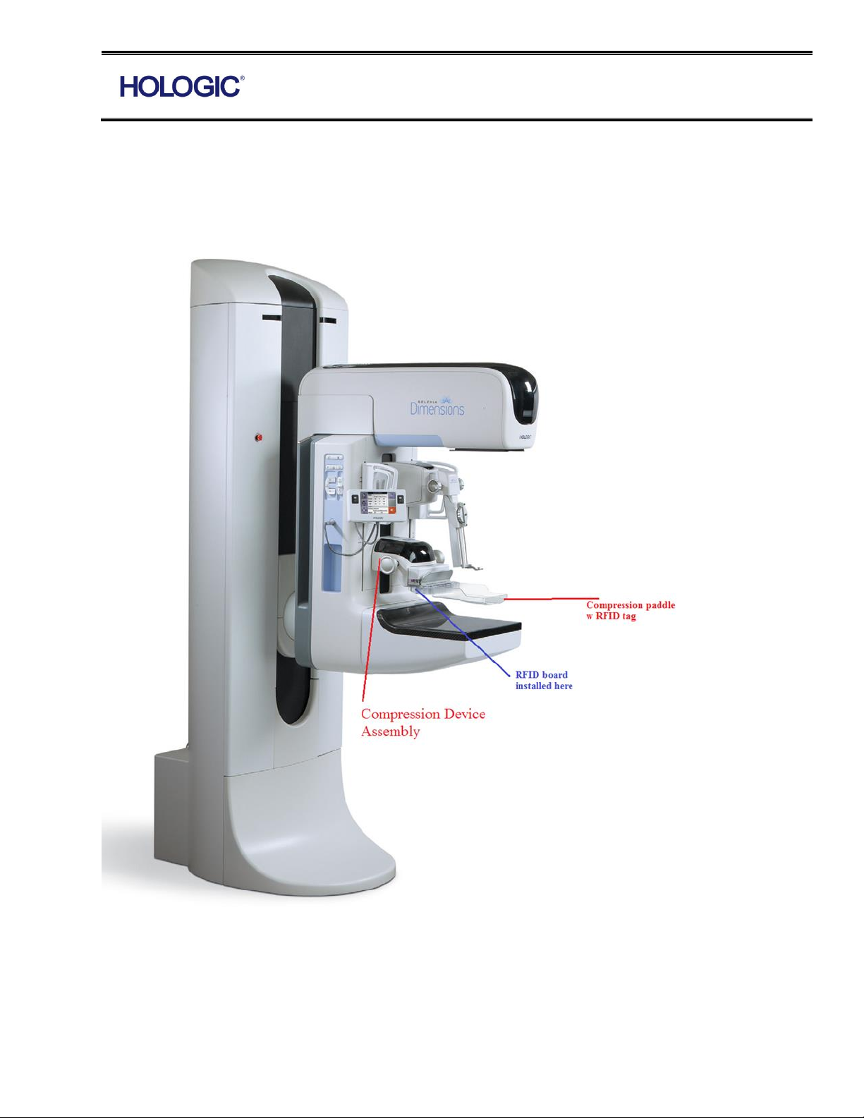
Hologic Inc. currently manufactures an RFID interface board that is used to detect the breast
compression paddle in Hologic mammography equipment. RFID board as a module is installed in
the COMPRESSION DEVICE assembly. Corresponding tag is located in the breast compression
paddle as seen below.
RFID Board Instructions for FCC & IC Filing
Form ENG-0013-T01, Rev. 002
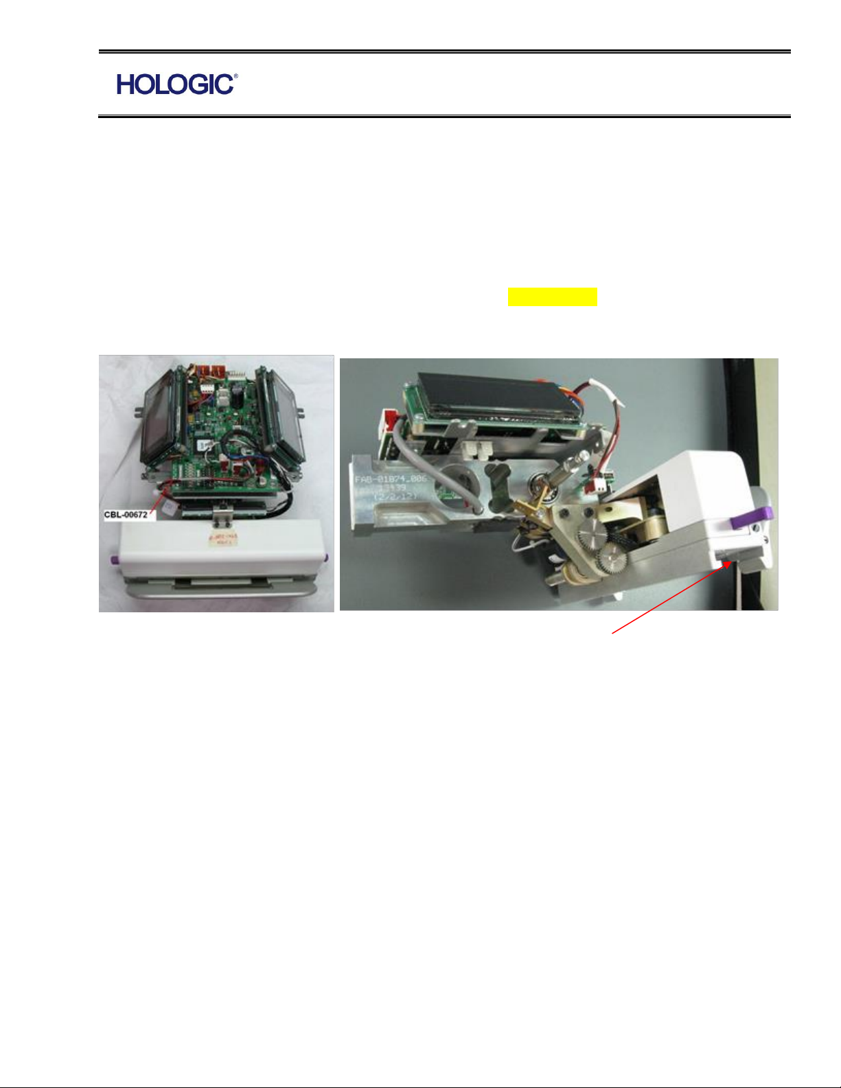
The circuit board contains a microcontroller to simulate I
2
C functionality, an I
2
C based A/D
converter, an integrated PCB printed antenna, and additional supporting circuitry. The board
interfaces with the rest of the system through a single 4-pin header consisting of power, ground
and I
2
C bus.
Compression Device Assembly is performed per assembly procedure AP-03659.
RFID board in addressed in step 2.16 through 2.18
2.16 Attach completed VCD display to top of the load cell using (3) 6-32 x 5/8” Pan Head Phillips
SEMS (2-500-9772). Attach ‘DJ4’ of RFID Board assembly (PCB-01673) to the interface board
(PCB-00095). Shift the paddle assembly fully to the left, tie wrap (1-090-0179) the RFID cable to
the frame and return the paddle assembly to the center.
RFID Board Goes Here
2.17 Attach Shifting Breast Tray Harness (CBL-00672) to ‘EJ1’ of the paddle position sensor
board (PCB-00186) and ‘DJ9’ of the compression device interface board (PCB-00095). Tie wrap (1-
090-0179) to frame.
2.18 Attach the MOTOR ASSY/CONNECTOR (MEL-00225) to ASSY.,COMP. DEVICE
INTERFACE BD (PCB-00095). Connect “DJ1” load cell cable to ASSY.,COMP. DEVICE
INTERFACE BD (PCB-00095). See wire routing photos below for detail on how to properly dress
the wire to ensure the compression device helmet can be properly mounted later.
 Loading...