

Page 1
Page 2

Page 3
Technical Support:
USA: +1.877.371.4372
Europe: +32.2.711.4690
Asia: +852 37-48-77-00
All Other: +1.781.999.7750
© Copyright Hologic 2010. All rights reserved. Printed in USA. This manual was originally written in English.
Hologic and the Hologic Logo are trademarks or registered trademarks of Hologic, Inc. Other trademarks registered or used by Hologic and its divisions and subsidiaries in the
United States and other countries include: Dimensions, DSM, FAST Paddle, HTC, MIMS plus, M-IV, MultiCare, SecurView, Selenia, Smart Paddle, SmartWindow, StereoLoc,
and TechMate. Microsoft and Windows are trademarks or registered trademarks of Microsoft Corporation in the United States and other countries. Any other product and
company names mentioned herein are the trademarks or registered trademarks of their respective owners.
Selenia Dimensions User Manual
Part Number MAN-01964
Revision 001
July 2010
Corporate Headquarters
35 Crosby Drive,
Bedford, MA 01730-1401 USA
Tel: +1.781.999.7300
Sales: +1.781.999.7453
Fax: +1.781.280.0668
www.hologic.com
Europe
(EU Representative)
Hologic NV
Leuvensesteenweg 250A
1800 Vilvoorde, Belgium
Tel: +32.2.711.4680
Fax: +32.2.725.2087
Refer to the corporate website for more facilities worldwide.
Page 4

Page 5

User Manual
Table of Contents
Table of Contents
List of Figures ix
List of Tables xi
Preface xiii
1.0 Intended Use ....................................................................................................................................... xiii
2.0 System Capabilities .............................................................................................................................. xiii
3.0 Users ................................................................................................................................................... xiii
4.0 Skills Needed for System Use .............................................................................................................. xiii
5.0 Training Requirements ......................................................................................................................... xiv
6.0 Quality Control Requirements ............................................................................................................. xiv
7.0 Hologic Cybersecurity Statement ......................................................................................................... xiv
8.0 Warnings, Cautions, and Notes ........................................................................................................... xiv
9.0 Terms and Definitions .......................................................................................................................... xv
10.0 International Symbols ........................................................................................................................ xvi
11.0 Document Standards ......................................................................................................................... xvi
Chapter 1—General Information 1
1.0 System Description .................................................................................................................................1
2.0 Safety Information .................................................................................................................................. 1
2.1 General Safety .................................................................................................................................. 1
2.2 Patient Safety ...................................................................................................................................3
2.3 Radiation Safety ............................................................................................................................... 4
2.4 Data Loss ......................................................................................................................................... 5
2.5 Equipment Damage .......................................................................................................................... 5
2.6 Emergency Off Switches ................................................................................................................... 5
2.7 Interlocks .........................................................................................................................................6
3.0 Compliance ............................................................................................................................................7
3.1 Compliance Requirements ...............................................................................................................7
3.2 Compliance Statements .................................................................................................................... 7
4.0 Label Locations ......................................................................................................................................8
Chapter 2—System Controls and Indicators 9
1.0 System Power Controls ........................................................................................................................... 9
2.0 Acquisition Workstation Controls and Display ...................................................................................... 10
2.1 Keyboard .......................................................................................................................................11
2.2 Bar Code Reader ............................................................................................................................11
2.3 Acquisition Workstation Touchscreen Display ............................................................................... 11
2.4 Preview Display .............................................................................................................................11
3.0 Tubestand Controls and Indicators ........................................................................................................ 12
3.1 C-arm Controls ............................................................................................................................... 13
3.2 Compression Device Controls and Displays ...................................................................................13
3.3 Tubehead Display ..........................................................................................................................14
3.4 Dual Function Footswitches ...........................................................................................................14
P/N MAN-01964 Revision 001 v
DRAFT
Preview copy—Generated 7/9/2010
Page 6

User Manual
Table of Contents
4.0 How to Turn On the Selenia Dimensions ............................................................................................. 15
4.1 Preparation .................................................................................................................................... 15
4.2 Startup ........................................................................................................................................... 15
4.3 Log In ............................................................................................................................................ 16
5.0 Perform the Functional Tests ................................................................................................................ 17
6.0 How to Turn Off the System ................................................................................................................. 23
7.0 How to Remove All Power from the Acquisition Workstation .............................................................. 23
Chapter 3—The User Interface 25
1.0 Select the Function to Perform ............................................................................................................. 25
2.0 How to Perform the Quality Control Tasks ........................................................................................... 26
3.0 How to Select a Patient ........................................................................................................................ 27
3.1 How to Open a Procedure ............................................................................................................. 27
3.2 How to Add a New Patient ............................................................................................................ 28
3.3 How to Edit the Patient Information ............................................................................................... 28
3.4 How to Delete a Patient ................................................................................................................ 28
3.5 How to Use a Patient Filter ............................................................................................................ 29
3.6 How to Refresh the Worklist .......................................................................................................... 29
3.7 How to Query the Worklist ........................................................................................................... 30
3.8 About the Admin Button ................................................................................................................ 30
3.9 How to Log Out ............................................................................................................................ 30
4.0 The Procedure Screen .......................................................................................................................... 31
4.1 How to Set the Exposure Parameters .............................................................................................. 31
4.2 How to Use the Implant Present Button ......................................................................................... 32
4.3 How to Acquire an Image .............................................................................................................. 32
4.4 How to Add or Remove a View ..................................................................................................... 33
4.5 How to Add a Procedure ............................................................................................................... 34
4.6 How to Edit a View ....................................................................................................................... 34
4.7 How to Close a Procedure ............................................................................................................. 35
5.0 How to Access Image Review Features ................................................................................................ 35
6.0 How to Use the Output Sets ................................................................................................................. 35
6.1 How to Select an Output Set ......................................................................................................... 35
6.2 How to Add or Edit an Output Set ................................................................................................. 35
7.0 How to Use the On-Demand Outputs .................................................................................................. 36
7.1 How to Archive ............................................................................................................................. 36
7.2 How to Print .................................................................................................................................. 37
7.3 How to Export ............................................................................................................................... 38
8.0 How to Use the Paddle Shift Feature .................................................................................................... 38
9.0 About the Taskbar ................................................................................................................................ 39
Chapter 4—The Images 41
1.0 Introduction ......................................................................................................................................... 41
1.1 Conventional Sequence of Events .................................................................................................. 41
1.2 Tomosynthesis Sequence of Events (Tomosynthesis option) ........................................................... 41
2.0 How to Review the Images .................................................................................................................. 42
2.1 The Image Review Tools Tab ......................................................................................................... 43
2.2 Other Image Review Tools ............................................................................................................ 44
2.3 How to Correct and Reprocess Implant Images .............................................................................. 45
3.0 Send the Images to the Output Devices ................................................................................................ 45
vi P/N MAN-01964 Revision 001
DRAFT Preview copy—Generated 7/9/2010
Page 7

User Manual
Table of Contents
Chapter 5—How to Use the Accessories 47
1.0 Introduction .......................................................................................................................................... 47
2.0 How to Install Accessories on the C-arm .............................................................................................. 47
3.0 The Patient Face Shields .......................................................................................................................48
3.1 How to Install or Remove the Conventional Face Shield ................................................................48
3.2 How to Install or Remove the Retractable Face Shield .................................................................... 49
3.3 How to Use the Retractable Face Shield .........................................................................................50
4.0 Compression Paddles ...........................................................................................................................51
4.1 Routine Screening Paddles ............................................................................................................. 51
4.2 Contact and Spot Compression Paddles ......................................................................................... 51
4.3 Localization Paddles ...................................................................................................................... 52
4.4 Magnification Paddles ....................................................................................................................52
4.5 How to Install or Remove a Compression Paddle ........................................................................... 53
4.6 Maintenance and Cleaning ............................................................................................................53
4.7 Paddle Shift .................................................................................................................................... 53
4.8 FAST Compression Mode ............................................................................................................... 54
5.0 Magnification Stand ..............................................................................................................................55
5.1 How to Install and Remove the Magnification Stand ......................................................................55
6.0 Crosshair Devices .................................................................................................................................56
6.1 How to Install and Remove the Localization Crosshair Device .......................................................56
6.2 How to Use the Localization Crosshair Device .............................................................................. 56
6.3 How to Install and Remove the Magnification Crosshair Device .................................................... 57
6.4 How to Align the Crosshair Device ................................................................................................ 57
Chapter 6—Clinical Procedures 59
1.0 Standard Workflow ...............................................................................................................................59
2.0 Example Screening Procedure ..............................................................................................................60
2.1 How to Position the Patient ............................................................................................................60
2.2 Set the Exposure Techniques ..........................................................................................................60
2.3 How to Acquire the Exposure ......................................................................................................... 61
2.4 How to Automatically Store the Image ...........................................................................................61
2.5 How to Accept a Rejected Image ................................................................................................... 61
2.6 How to Accept or Reject a Pended Image ...................................................................................... 61
Chapter 7—Maintenance and Cleaning 63
1.0 General Information ............................................................................................................................. 63
1.1 For General Cleaning ..................................................................................................................... 63
1.2 To prevent Possible Injury or Equipment Damage ..........................................................................64
2.0 Acquisition Workstation .......................................................................................................................65
2.1 How to Clean the Preview Display .................................................................................................65
2.2 How to Clean the Touchscreen Display ......................................................................................... 65
2.3 How to Clean the Keyboard ........................................................................................................... 65
2.4 How to Clean the Fingerprint Reader ............................................................................................. 65
Chapter 8—System Administration Interface 67
1.0 How to Use the Admin Screen ............................................................................................................. 67
2.0 How to Use the System Tools ...............................................................................................................70
2.1 The Radiologic Technologist Manager ........................................................................................... 70
P/N MAN-01964 Revision 001 vii
DRAFT
Preview copy—Generated 7/9/2010
Page 8

User Manual
Table of Contents
Appendix A—Specifications 73
1.0 Product Measurements ......................................................................................................................... 73
1.1 Tubestand (Gantry with C-arm) ...................................................................................................... 73
1.2 Acquisition Workstation ................................................................................................................ 74
2.0 Operation and Storage Environment .................................................................................................... 75
2.1 General Conditions for Operation ................................................................................................. 75
2.2 Storage Environment ...................................................................................................................... 75
3.0 Acquisition Workstation Technical Information ................................................................................... 75
4.0 Electrical Input ..................................................................................................................................... 76
4.1 Tubestand ...................................................................................................................................... 76
4.2 Acquisition Workstation ................................................................................................................ 76
5.0 Tubestand Technical Information ......................................................................................................... 76
5.1 C-arm ............................................................................................................................................ 76
5.2 Compression ................................................................................................................................. 77
5.3 X-ray Tube ..................................................................................................................................... 77
5.4 X-ray Beam Filtration and Output .................................................................................................. 78
5.5 X-ray Collimation .......................................................................................................................... 79
5.6 Light Field Indication ..................................................................................................................... 79
5.7 X-ray Generator ............................................................................................................................. 79
6.0 Imaging System Technical Information ................................................................................................. 79
6.1 Image Receptor ............................................................................................................................. 79
Appendix B—The System Messages and Alert Messages 81
1.0 Error Recovery and Troubleshooting .................................................................................................... 81
2.0 Types of Messages and Alert messages ................................................................................................. 81
2.1 Fault Levels ................................................................................................................................... 81
2.2 System Messages ........................................................................................................................... 82
List of Addenda 83
Index 85
viii P/N MAN-01964 Revision 001
DRAFT Preview copy—Generated 7/9/2010
Page 9

User Manual
List of Figures
List of Figures
Figure 1-1: Selenia Dimensions .................................................................................................................... 1
Figure 1-2: Label Locations........................................................................................................................... 8
Figure 2-1: System Power Controls ............................................................................................................... 9
Figure 2-2: Acquisition Workstation Controls and Displays ........................................................................ 10
Figure 2-3: Tubestand Controls and Indicators............................................................................................ 12
Figure 2-4: C-arm Controls ......................................................................................................................... 13
Figure 2-5: Compression Device................................................................................................................. 13
Figure 2-6: Compression Display................................................................................................................ 13
Figure 2-7: Tubehead Display..................................................................................................................... 14
Figure 2-8: Dual Function Footswitches...................................................................................................... 14
Figure 2-9: The Startup Screen.................................................................................................................... 15
Figure 2-10: How to Log In......................................................................................................................... 16
Figure 2-11: C-arm Controls (left side shown) ............................................................................................. 17
Figure 2-12: Power Buttons ........................................................................................................................ 23
Figure 3-1: An Example Select Function to Perform Screen ......................................................................... 25
Figure 3-2: An Example Gain Calibration Screen ........................................................................................ 26
Figure 3-3: How to Select a Patient............................................................................................................. 27
Figure 3-4: How to Add a New Patient ....................................................................................................... 28
Figure 3-5: The Filter Tab in the Patient Filter Screen .................................................................................. 29
Figure 3-6: An Example Generator Tab in the Procedure Screen ................................................................. 31
Figure 3-7: The Add View Screen ............................................................................................................... 33
Figure 3-8: The Add Procedure Dialog Box ................................................................................................ 34
Figure 3-9: The Edit View Screen................................................................................................................ 34
Figure 3-10: The Print Screen ..................................................................................................................... 37
Figure 4-1: The Preview Screen .................................................................................................................. 41
Figure 4-2: The Tools Tab in the Procedure Screen ..................................................................................... 42
Figure 4-3: Marked Images in a Procedure.................................................................................................. 42
Figure 4-4: Image Review Tools.................................................................................................................. 43
Figure 4-5: Image Review Tabs ................................................................................................................... 44
Figure 4-6: Icons Available on the Notices Tab........................................................................................... 44
Figure 4-7: The Exposure Index .................................................................................................................. 44
Figure 5-1: C-arm Accessories .................................................................................................................... 47
Figure 5-2: How to Install the Conventional Face Shield............................................................................. 48
Figure 5-3: How to Align the Retractable Face Shield on the C-arm............................................................ 49
Figure 5-4: Installation ................................................................................................................................ 50
Figure 5-5: Operation ................................................................................................................................. 50
Figure 5-6: How to Install a Compression Paddle ....................................................................................... 53
Figure 5-7: How to Remove the Compression Paddle ................................................................................. 53
Figure 5-8: The FAST Compression Mode Slide .......................................................................................... 54
Figure 5-9: Installation of the Magnification Stand ...................................................................................... 55
Figure 5-10: How to Attach the Localization Crosshair Device ................................................................... 56
Figure 5-11: How to Install and Remove the Magnification Crosshair Device ............................................. 57
Figure 6-1: Screening Example, Conventional Procedure ............................................................................ 60
Figure 8-1: The Admin Screen .................................................................................................................... 68
Figure A-1: Tubestand Dimensions ............................................................................................................. 73
Figure A-2: Acquisition Workstation Dimensions........................................................................................ 74
P/N MAN-01964 Revision 001 ix
DRAFT
Preview copy—Generated 7/9/2010
Page 10

User Manual
List of Figures
x P/N MAN-01964 Revision 001
DRAFT Preview copy—Generated 7/9/2010
Page 11

User Manual
List of Tables
List of Tables
Table 2-1: C-arm Functional Tests ...............................................................................................................17
Table 3-1: Taskbar Menus ........................................................................................................................... 39
Table 8-1: Admin Screen Functions ............................................................................................................. 69
Table 8-2: Radiologic Technologist Manager—Service Tools Functions.......................................................71
Table A-1: mA Setting as a Function of kV...................................................................................................78
Table B-1: System Messages ........................................................................................................................82
P/N MAN-01964 Revision 001 xi
DRAFT
Preview copy—Generated 7/9/2010
Page 12

User Manual
List of Tables
xii P/N MAN-01964 Revision 001
DRAFT Preview copy—Generated 7/9/2010
Page 13

Preface
1.0 Intended Use
The Hologic Selenia® Dimensions® Digital Breast Tomosynthesis System generates digital
mammographic images that can be used for screening and diagnosis of breast cancer. The
Selenia Dimensions system is intended for use in the same clinical applications as Full Field
Digital Mammography systems for screening mammograms. Specifically, the Selenia
Dimensions system can be used to acquire two-dimensional full field digital mammograms
and three-dimensional tomosynthesis mammograms. The screening examination will consist
of a two-dimensional image set or a two-dimensional and tomosynthesis image set. The
Selenia Dimensions system may also be used for additional diagnostic workup of the breast.
2.0 System Capabilities
The system provides the user interfaces for the performance of screening and diagnostic
mammograms:
• Conventional mammography with a digital image receptor equivalent in size to large
mammography film.
• Tomosynthesis scan with a digital image receptor equivalent in size to large
mammography film (Tomosynthesis option).
• Conventional digital mammogram and tomosynthesis scan during one compression
(Tomosynthesis option).
User Manual
Preface
Intended Use
3.0 Users
• A Technologist to acquire and review images
• A Technologist with the manager
• A system administrator to enable permissions
• A Medical Physicist to perform the Quality Control tests
• A Radiologist can use the system with a Technologist
• The service personnel to install the system, set the site system configurations and
calibrations, and find faults
4.0 Skills Needed for System Use
You must know how to do the following:
• Perform the trackball operations, like click, drag, and/or select
• Perform the touchscreen operations
• Select from menus
• Type information in text fields
• Select the options in the screens
• Select the entries from drop-down lists
• Use scroll bars
permissions to perform the Quality Assurance
P/N MAN-01964 Revision 001 xiii
DRAFT
Preview copy—Generated 7/9/2010
Page 14

User Manual
Preface
Training Requirements
5.0 Training Requirements
Hologic™ does not accept the responsibility for injury or damage from wrong system
operation.
Make sure that you receive training on the Selenia Dimensions before use on patients.
Hologic training programs address MQSA training regulations for any Technologist or
Physician.
Refer to this manual for directions on how to use Selenia Dimensions.
6.0 Quality Control Requirements
The facilities in the United States must use the Quality Control Manual to create a Quality
Assurance and Quality Control program. The facility must create the program to meet the
requirements of the Mammography Quality Standards Act or to be accredited by ACR or
another accreditation body.
The facilities outside the United States can use the Quality Control Manual as a guide to
create a program to meet the local standards and regulations.
7.0 Hologic Cybersecurity Statement
Hologic continuously tests the current state of computer and network security to examine
possible security problems. When necessary, Hologic provides the updates to the product.
For Cybersecurity Best Practices documents for Hologic products, refer to the Hologic
Internet site.
8.0 Warnings, Cautions, and Notes
Descriptions of Warnings, Cautions, and Notes used in this manual:
WARNING! Procedures that you must follow accurately to prevent
possible serious injury or death.
Warning: Procedures that you must follow accurately to prevent injury.
Caution: Cautions point out procedures that you must follow accurately to
prevent the damage to equipment, loss of data, or damage to files in
software applications.
Note… Notes indicate additional information.
xiv P/N MAN-01964 Revision 001
DRAFT Preview copy—Generated 7/9/2010
Page 15

9.0 Terms and Definitions
ACR American College of Radiology
AEC Automatic Exposure Control
Annotations Graphic or text marks on an image to indicate an area of interest.
Collimator Device at the x-ray tube to control the area of the receptor
Combo Procedure An image acquisition procedure for which the system takes
Conventional Mammography Single projection x-ray images of views for screening and
Diagnostic Workstation Softcopy workstation for diagnoses from digital images.
DICOM Digital Imaging and Communications in Medicine
Gantry A part of the Selenia Dimensions that has the Detector,
Grid Element within the Digital Image Receptor that reduces
HIS Hospital Information System
HTC™ High Transmission Cellular Grid
Image Receptor Assembly of x-ray detector, x-ray scatter reduction grid,
MQSA Mammography Quality Standards Act
Notice Annotations and comments per image communicated
PACS Picture Archiving and Communications System. A
Pend A mark on the image to indicate the Technologist is not
Projection Images The group of x-ray images for tomosynthesis taken at
RIS Radiology Information System
ROI Region of Interest
SID Source to Image Distance
Tomosynthesis An imaging procedure which combines a number of
UPS Uninterruptible Power Supply
User Manual
Preface
Ter ms an d Definitions
that is exposed.
a conventional mammography image and a tomosynthesis
scan during a single patient compression (Tomosynthesis
option).
diagnostic purposes.
Generator and x-ray Source, Positioning/Compression,
Power Distribution, and Accessories Subsystems.
scatter radiation during the exposure.
and carbon fiber cover.
between Diagnostic Review Workstations, Technologist
Workstations, and Acquisition Workstations.
computer and network system for the transfer and archive
of digital medical images.
positive about the image quality. Pended images must be
Accepted or Rejected before the procedure is closed.
different projection angles through the breast
(Tomosynthesis option).
projections taken at different angles. The tomosynthesis
images can be reconstructed to show planes or slices
within the object (Tomosynthesis option).
P/N MAN-01964 Revision 001 xv
DRAFT
Preview copy—Generated 7/9/2010
Page 16
User Manual
Preface
International Symbols
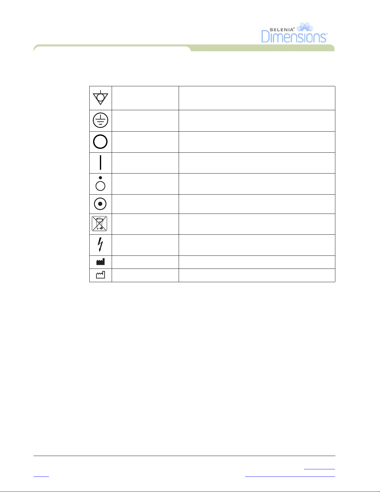
10.0 International Symbols
This section describes the International Symbols on the Selenia Dimensions.
Potential Equalization
terminal
Protective Earth
terminal
Off Power disconnected from the main power source.
On Power connection to the main power source.
Off
On
WEEE
Dangerous Voltage Identifies an area of possible lethal voltage.
Manufacturer
Connection for a conductor different from the Protective
Earth for a direct connection between two or more pieces
of electrical equipment.
For the connection of the line cord ground or ground
cable of the equipment and there is no other purpose.
Only a part of the equipment is disconnected from the
main power source.
Only a part of the equipment is connected to the main
power source.
Symbol that indicates separate removal for electrical and
electronic equipment.
Date of Manufacture
11.0 Document Standards
When prompted to add text, enter the text written in monospaced fo nt exactly as
shown.
xvi P/N MAN-01964 Revision 001
DRAFT Preview copy—Generated 7/9/2010
Page 17
Chapter 1—General Information
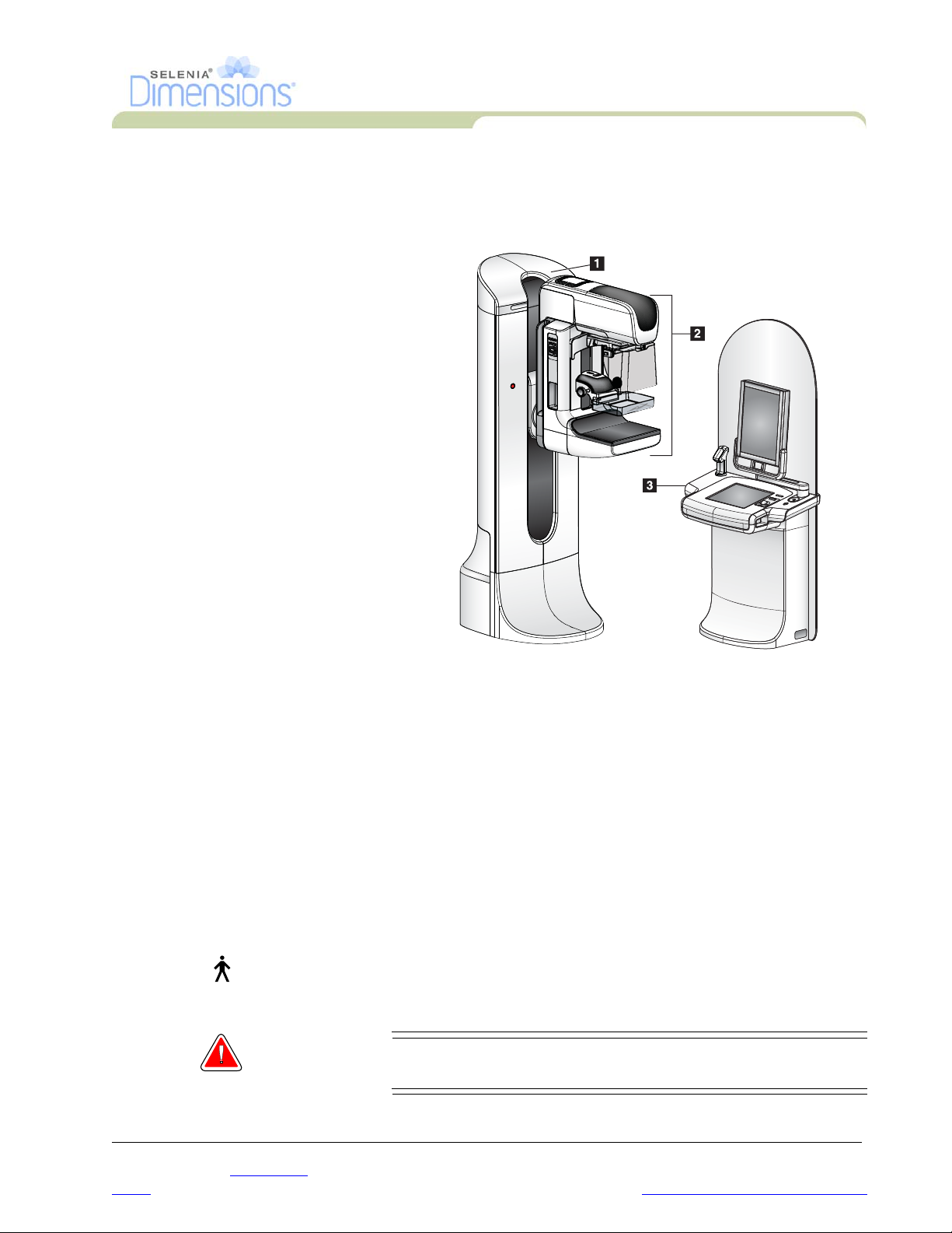
1.0 System Description
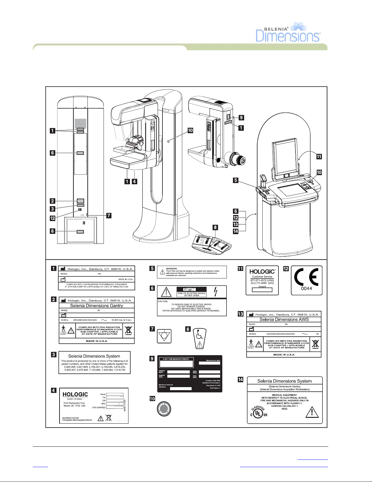
Legend for Figure1-1
1. Gantry
2. C-arm
3. Acquisition Workstation
User Manual
Chapter 1—General Information
System Description
2.0 Safety Information
Read and understand this manual before you use the system. Keep the manual available
during the patient procedures.
Always follow all the instructions in this manual. Hologic does not accept the responsibility
for injury or damage from wrong system operation. Hologic can arrange for training at your
facility.
The Selenia Dimensions has protective devices, but the Technologist must understand how
to safely use the system. The Technologist must remember the health hazards of x-rays.
2.1 General Safety
The Selenia Dimensions system is classified as CLASS I, TYPE B APPLIED PART, IPX0,
permanently connected equipment, continuous operation with short term loading per IEC
60601-1. There are no special provisions to protect the system from flammable anesthetics
or ingress of liquids.
WARNING! Lethal voltages exist inside of this system. Do not open any
Figure 1-1: Selenia Dimensions
of the panels.
P/N MAN-01964 Revision 001 1
DRAFT
Preview copy—Generated 7/9/2010
Page 18
User Manual
Chapter 1—General Information
Safety Information
WARNING! Per North American electrical safety requirements, you
WARNING! Do not use the electrical equipment near flammable
Warning: This device contains dangerous material. Return to Hologic all
Warning: The user or the service personnel must correct problems before
must use a Hospital Grade receptacle to provide a correct
Ground.
anesthetics.
material removed from service.
the system is used.
Warning: The user must arrange for preventive maintenance by an
authorized service representative.
Warning: If a paddle touches possible infectious materials, call your
Infection Control Representative for decontamination
instructions.
Caution: The system is a medical device and not a normal computer. Do not
make changes to the hardware or software that are not authorized.
Install this device behind a firewall for network security. The
computer virus protection or network security for this medical device
is not provided (for example, a computer firewall). The network
security and anti-virus provisions are the responsibility of the user.
Caution: Only use the approved accessories with this equipment. The failure to
follow this caution can cause errors and possible data loss.
Note… Hologic does not provide the Gantry power cable for some countries. If
the power cable is not provided, the installed cable must meet the
following requirements and all local codes that apply: 3 conductor, 8
2
AWG (10 mm
) copper not more than 25 feet (7.62 meters) in length.
2 P/N MAN-01964 Revision 001
DRAFT Preview copy—Generated 7/9/2010
Page 19
2.2 Patient Safety
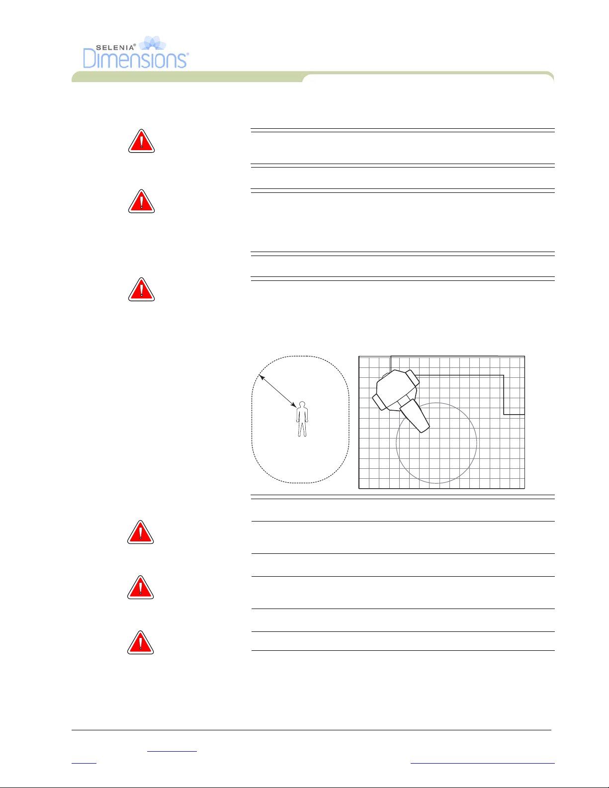
WARNING! After power failure, remove the patient from the system
WARNING! To keep the isolation quality for the system, attach only
WARNING! Keep a 1.5 meter safe distance between the patient and
User Manual
Chapter 1—General Information
Safety Information
before you apply power.
approved accessories or options to the system. Only the
authorized personnel can make changes to the
connections.
any non-patient devices.
Non-patient system components (like the Workflow
Manager, the diagnostic review workstation, or the hard
copy printer) must not be installed in the Patient Area.
1.5m
Warning: Never leave the patient during the procedure if in contact with
the mammography system.
Warning: Keep the hands of the patient away from all buttons and
switches at all times.
Warning: The C-arm movement has drive motors.
P/N MAN-01964 Revision 001 3
DRAFT
Preview copy—Generated 7/9/2010
Page 20

User Manual
Chapter 1—General Information
Safety Information
Warning: You increase the patient dose to high levels if you increase the
Warning: Put both footswitches away from the patient and C-arm area to
Warning: Control the access to the equipment according to local
2.3 Radiation Safety
AEC exposure adjustment setting. You increase the image noise
or decrease image quality if you decrease the AEC exposure
adjustment setting.
prevent any accidental footswitch use. When the patient has a
wheelchair, put the footswitches away from the area.
regulations for radiation protection.
WARNING! This x-ray system can be dangerous to the patient and the
user. Always follow the safety precautions for x-ray
exposures.
Warning: For exposures except magnification case studies, always use the
Face Shield.
Warning: The Face Shield does not protect from radiation.
WARNING! The disk drives installed in this system are a Class I Laser
Product. Prevent direct exposure to the beam. Hidden
laser radiation exists if the case to a disk drive is open.
Warning: The bar code reader installed in this system is a Class II Laser
Product. Prevent direct exposure to the beam. Hidden laser
radiation exists if the cover is opened.
Warning: You must keep your complete body behind the radiation shield
for the time of the exposure for maximum protection from x-ray
exposure.
4 P/N MAN-01964 Revision 001
DRAFT Preview copy—Generated 7/9/2010
Page 21

2.4 Data Loss
Warning: Do not move the C-arm while the system retrieves the image.
Caution: Never turn off the Acquisition Workstation Circuit Breaker except in
emergency. The circuit breaker can turn off the Uninterruptible Power
Supply (UPS) and risk data loss.
Caution: Do not put any magnetic media near or on devices that create any
magnetic fields, because stored data can be lost.
2.5 Equipment Damage
Caution: Do not put any heat source on the image receptor.
User Manual
Chapter 1—General Information
Safety Information
Caution: To minimize possible damage from thermal shock to the Digital Image
Receptor, follow the recommended procedure to turn off the
equipment.
Caution: Do not make any brightness or contrast adjustments to the display
unless the SMPTE test pattern is on the screen.
Caution: Use the least possible amount of cleaning fluids. The fluids must not
flow or run.
Caution: Do not spray disinfectant on the system, because the moisture can
enter the system and damage the electronic components.
2.6 Emergency Off Switches
The Emergency Off switches remove the power from the Gantry. Do not normally use the
Emergency Off switches to turn off the system. See Chapter 2, page 23 for complete
information.
P/N MAN-01964 Revision 001 5
DRAFT
Preview copy—Generated 7/9/2010
Page 22

User Manual
Chapter 1—General Information
Safety Information
2.7 Interlocks
The Selenia Dimensions has safety interlocks:
• The C-arm vertical drive and rotation is disabled when 45 Newtons (10 pounds) or
greater of compression force is displayed.
• If the x-ray button is released before the end of the exposure, the exposure stops and an
alarm message appears.
• When in Tomo mode, the system does not allow the Grid in the x-ray field
(Tomosynthesis option).
• Mirror and Filter interlocks prevent the x-ray exposure when the Light Field Mirror or the
Filter is not aligned.
6 P/N MAN-01964 Revision 001
DRAFT Preview copy—Generated 7/9/2010
Page 23

3.0 Compliance
This section describes the mammography system compliance requirements and the
responsibilities of the manufacturer.
3.1 Compliance Requirements
The manufacturer has the responsibility for the safety, reliability, and performance of this
equipment with the following provisions:
• The electrical installation of the room meets all requirements.
• The equipment is used according to Instructions for Use.
• The assembly operations, extensions, adjustments, changes, or repairs are performed
only by authorized persons.
• The network and communication equipment must be installed to meet IEC Standards.
The complete system (network and communications equipment and Selenia Dimensions
Mammography System) must be in compliance with IEC 60601-1 and IEC 60601-1-1.
3.2 Compliance Statements
User Manual
Chapter 1—General Information
Compliance
The manufacturer states this device is made to meet the following requirements:
• CAN/CSA ISO 13485:2003
• EN 60601-1:1990 +A1+A11+A12+A2+A13 Medical Electrical Equipment—General
Requirements for Basic Safety and Essential Performance
• FDA, 21 CFR [Parts 820, 900 and 1020]
• IEC 60601-1:1988 +A1+A2:1995 +A13:1996 Medical Electrical Equipment—General
Requirements for Safety
• IEC 60601-1-1:2000-12 Medical Electrical Equipment—Collateral Standard: Safety
Requirements for Medical Electrical Systems
• IEC 60601-1-2:2001 Medical Electrical Equipment—Collateral Standard:
Electromagnetic Compatibility for Medical Electric Systems
• IEC 60601-1-3:1994 Medical Electrical Equipment—Collateral Standard: Requirements
for Radiation Protection in Diagnostic X-ray Equipment
• IEC 60601-1-4:1996 +A1:1999 Medical Electrical Equipment—Collateral Standard:
Programmable Electrical Medical Systems
• IEC 60601-2-7:1998 Medical Electrical Equipment—Particular Requirements for the
Safety of High-Voltage Generators of Diagnostic X-ray Equipment
• IEC 60601-2-28:1993-03 Medical Electrical Equipment—Particular Requirements for the
Safety of X-ray Source Assemblies and X-ray Tube Assemblies for Medical Diagnosis
• IEC 60601-2-32:1994 Medical Electrical Equipment—Particular Requirements for the
Safety of Associated Equipment of X-ray Equipment
• IEC 60601-2-45:2001 Medical Electrical Equipment—Particular Requirements for the
Safety of Mammographic X-ray Equipment and Mammographic Stereotactic Devices
• UL 60601-1: Medical Electrical Equipment, Part 1—General Requirements for Safety
• CAN/CSA: Medical Electrical Equipment Part 1: C22.2 No. 601.1–M90—General
Requirements for Safety
P/N MAN-01964 Revision 001 7
DRAFT
Preview copy—Generated 7/9/2010
Page 24
User Manual
Chapter 1—General Information
Label Locations
4.0 Label Locations
Figure 1-2: Label Locations
8 P/N MAN-01964 Revision 001
DRAFT Preview copy—Generated 7/9/2010
Page 25
Chapter 2—System Controls and Indicators
Chapter 2—System Controls and Indicators
1.0 System Power Controls
User Manual
System Power Controls
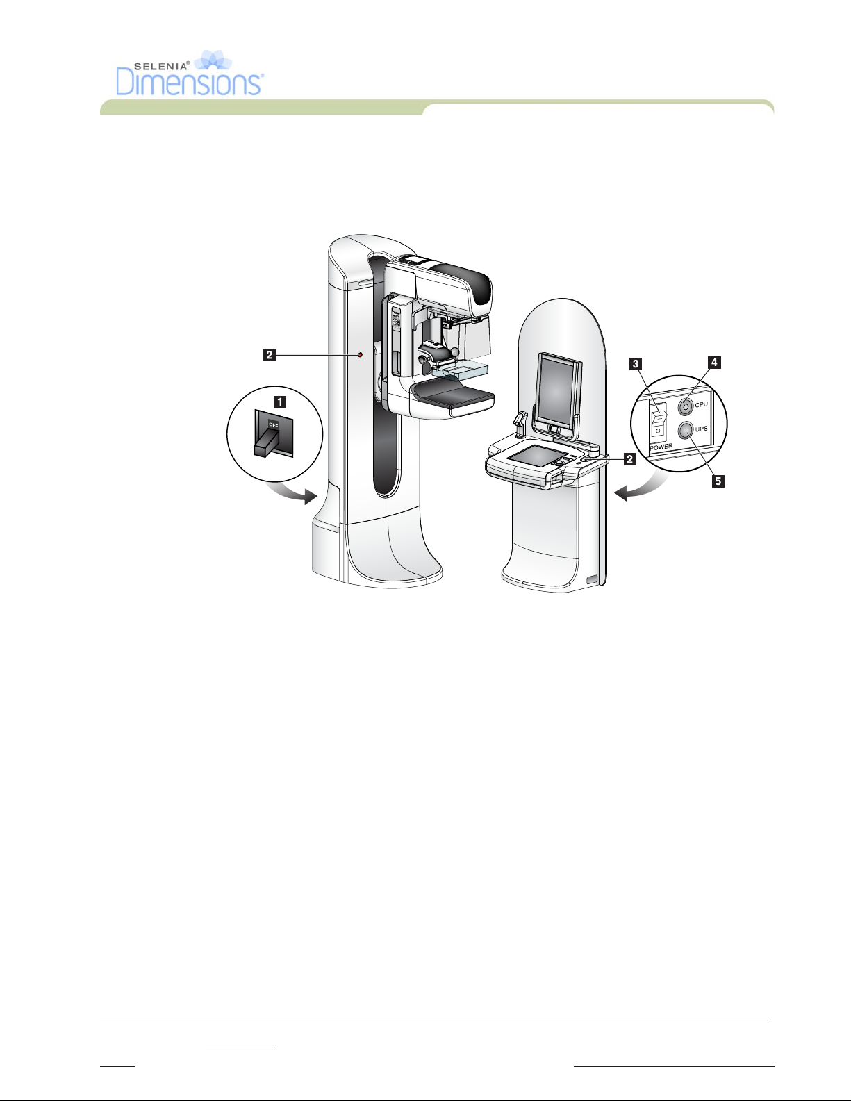
Figure 2-1: System Power Controls
Legend for Figure 2-1
1. Gantry Power Circuit Breaker
2. Emergency Off Switch (two on the Gantry, one on the Acquisition Workstation)
3. Acquisition Workstation Power Circuit Breaker
4. Computer Power Button
5. UPS Power Button
P/N MAN-01964 Revision 001 9
DRAFT
Preview copy—Generated 7/9/2010
Page 26

User Manual
Chapter 2—System Controls and Indicators
Acquisition Workstation Controls and Display
2.0 Acquisition Workstation Controls and Display
Figure 2-2: Acquisition Workstation Controls and Displays
Legend for Figure2-2
1. Trackball
2. Scroll Wheel
3. Compression Release
4. Emergency Off Switch
5. Fingerprint Reader
6. X-ray Button (one on each side)
7. Touchscreen Display
8. Keyboard (in drawer)
9. CD/DVD Drive
10. Bar Code Reader
11. LED for Preview Display Power
12. Preview Display
10 P/N MAN-01964 Revision 001
DRAFT Preview copy—Generated 7/9/2010
Page 27

Chapter 2—System Controls and Indicators
Acquisition Workstation Controls and Display
2.1 Keyboard
Use the keyboard in the front drawer of the Acquisition Workstation for data entry.
2.2 Bar Code Reader
Use this device for data entry from bar codes for patient or procedure records.
2.3 Acquisition Workstation Touchscreen Display
Use the Touchscreen or trackball to select items.
2.4 Preview Display
See the images on the Preview Display.
User Manual
P/N MAN-01964 Revision 001 11
DRAFT
Preview copy—Generated 7/9/2010
Page 28
User Manual
Chapter 2—System Controls and Indicators
Tubestand Controls and Indicators
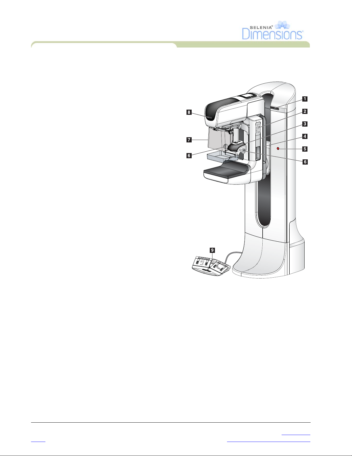
3.0 Tubestand Controls and Indicators
Legend for Figure2-3
1. The Rotation Angle Displays (each side)
2. The C-arm Controls (each side)
3. The Compression Device
4. The Patient Handles (each side)
5. The Emergency Off Switches (each side)
6. The Compression Handwheels
7. The Patient Face Shield
8. The Tubehead Display
9. The Footswitches
Figure 2-3: Tubestand Controls and Indicators
12 P/N MAN-01964 Revision 001
DRAFT Preview copy—Generated 7/9/2010
Page 29
3.1 C-arm Controls
AE
C
P
O
S
I
TIO
N
The C-arm Controls provide the
Collimator and C-arm functions.
See Section 5.0, page 17.
User Manual
Chapter 2—System Controls and Indicators
Tubestand Controls and Indicators
Figure 2-4: C-arm Controls
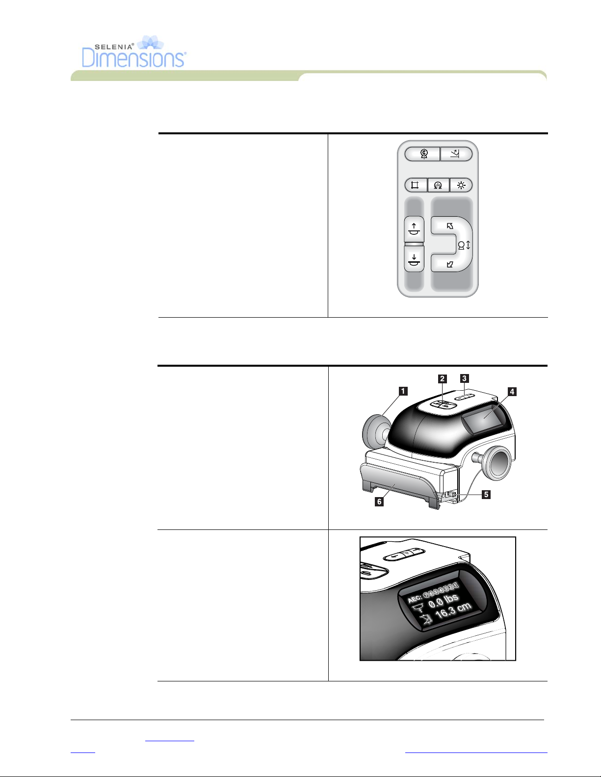
3.2 Compression Device Controls and Displays
Legend for Figure2-5
1. Manual Compression Handwheels
2. Paddle Shift Buttons
3. AEC Buttons
4. Compression Device Display
5. The FAST Compression Mode Slide
6. Paddle Clamp
Figure 2-5: Compression Device
The Display on the compression
device shows:
• AEC Sensor Position
• Compression Force (displays 0.0
when force is less than 4 pounds)
• Compression Thickness
• Angle of C-arm after rotation (for
10 seconds)
Figure 2-6: Compression Display
P/N MAN-01964 Revision 001 13
DRAFT
Preview copy—Generated 7/9/2010
Page 30
User Manual
COMPRESSION
C-ARM
Chapter 2—System Controls and Indicators
Tubestand Controls and Indicators
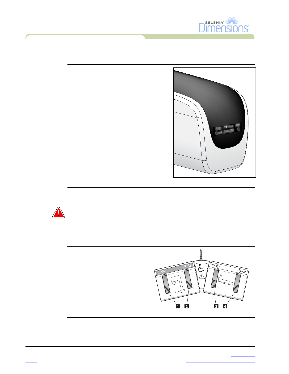
3.3 Tubehead Display
The Tubehead Display shows:
•SID
• Filter Type
• Collimator Setting
• Paddle Position
SID: 70 cm Rh
Coll: 24x29 C
3.4 Dual Function Footswitches
Warning: Put both footswitches away from the patient and C-arm area to
prevent any accidental footswitch use. When the patient has a
wheelchair, put the footswitches away from the area.
To use the footswitches:
1. Press the footswitch to actuate.
2. Release the switch to stop the
movement.
Legend for Figure2-8
1. C-arm Down
2. C-arm Up
3. Compression Down
4. Compression Up
Figure 2-7: Tubehead Display
Figure 2-8: Dual Function Footswitches
14 P/N MAN-01964 Revision 001
DRAFT Preview copy—Generated 7/9/2010
Page 31

Chapter 2—System Controls and Indicators
4.0 How to Turn On the Selenia Dimensions
4.1 Preparation
1. Reset all three Emergency Off switches.
2. Make sure that both system circuit breakers are in the On position.
3. Remove any obstructions to the C-arm movement and to the view of the Operator.
4.2 Startup
1. Press the UPS button at the rear of the Acquisition Workstation if the UPS was shut
down.
2. Press the computer power button at the rear of the Acquisition Workstation (see
Figure 2-1, page 9, number 4).
User Manual
How to Turn On the Selenia Dimensions
Figure 2-9: The Startup Screen
3. Select the Log In button.
Note…
Note… The Startup screen includes a Shutdown button that turns off the whole
P/N MAN-01964 Revision 001 15
DRAFT
The system requires between 5 minutes and 45 minutes to prepare for
image acquisition. The wait time depends on the detector power
configuration. A timer in the Taskbar displays the wait time before the
system is ready. Do not acquire clinical or QC images unless the System
Status Icon indicates the system is Ready.
system, and a Reboot button that restarts the system.
Preview copy—Generated 7/9/2010
Page 32

User Manual
Chapter 2—System Controls and Indicators
How to Turn On the Selenia Dimensions
4.3 Log In
Figure 2-10: How to Log In
When the user Log In screen displays, all Managers and Technologists show in the list of
Operators.
1. To display the Service, Applications, and Physicists user names, select the Show All
button.
2. Select your user name, enter your password, and select the Log In button.
Or
Validate your fingerprint.
16 P/N MAN-01964 Revision 001
DRAFT Preview copy—Generated 7/9/2010
Page 33

5.0 Perform the Functional Tests
Legend for Figure2-11
1. Compression Release
2. (Future use)
3. Light Field Lamp
4. (Future use)
5. Collimator Override
6. Clockwise C-arm Rotation
7. C-arm Up and Down
8. Counterclockwise C-arm
Rotation
9. Compression Up
10. Compression Down
A C-arm control panel is on
both the left and right sides
of the Gantry.
User Manual
Chapter 2—System Controls and Indicators
Perform the Functional Tests
Figure 2-11: C-arm Controls (left side shown)
The following Functional Tests make sure that the control operates correctly.
Table 2-1: C-arm Functional Tests
Function Functional Test
Compression Down Press a Compression Down button:
• The compression brake engages.
• The light field lamp illuminates.
• The compression device lowers.
Note… When you press the Compression Down button, the
compression brake remains engaged until the Compression
Release button is pressed.
Compression down movement stops:
• When you release the button.
• When you reach the Down Force limit.
• When you reach the Lower Travel limit.
P/N MAN-01964 Revision 001 17
DRAFT
Preview copy—Generated 7/9/2010
Page 34

User Manual
Chapter 2—System Controls and Indicators
Perform the Functional Tests
Function Functional Test
Compression Up Press a Compression Up button:
Compression Release Press the Compression Release button:
Table 2-1: C-arm Functional Tests
• The Compression Device moves toward the top.
• The Compression Up button does not release the
Compression Brake.
Compression Up movement automatically stops:
• When you release the button.
• When you reach the upper travel limit.
• The Compression Motor Brake releases.
• The Compression Device lifts.
C-arm Up Press the C-arm Up button:
• The C-arm movement automatically stops when the
button is released.
• The C-arm movement automatically stops when the
C-arm reaches the upper travel limit.
• The C-arm movement is disabled when a compression
force of 45 N (10 pounds) or greater is applied.
18 P/N MAN-01964 Revision 001
DRAFT Preview copy—Generated 7/9/2010
Page 35

Chapter 2—System Controls and Indicators
Perform the Functional Tests
Table 2-1: C-arm Functional Tests
Function Functional Test
C-arm Down Press the C-arm Down button:
• The C-arm movement automatically stops when the
button is released.
• The C-arm movement automatically stops when the
C-arm reaches the lower travel limit.
• The C-arm movement is disabled when a compression
force of 45 N (10 pounds) or greater is applied.
User Manual
P/N MAN-01964 Revision 001 19
DRAFT
Preview copy—Generated 7/9/2010
Page 36

User Manual
Chapter 2—System Controls and Indicators
Perform the Functional Tests
Function Functional Test
Table 2-1: C-arm Functional Tests
Counterclockwise C-arm
Rotation
Left Panel Right Panel
Clockwise C-arm Rotation Press the Clockwise C-arm Rotation button to start
Left Panel Right Panel
Press the Counterclockwise C-arm Rotation to start
counterclockwise C-arm rotation.
clockwise C-arm rotation.
20 P/N MAN-01964 Revision 001
DRAFT Preview copy—Generated 7/9/2010
Page 37

User Manual
Chapter 2—System Controls and Indicators
Perform the Functional Tests
Table 2-1: C-arm Functional Tests
Function Functional Test
C-arm Rotation Switch Push the C-arm Rotation switch away from you to move the
C-arm toward you.
Pull the C-arm Rotation switch toward you to move the
C-arm away.
The C-arm movement stops when the switch is released.
P/N MAN-01964 Revision 001 21
DRAFT
Preview copy—Generated 7/9/2010
Page 38

User Manual
A
E
C
P
O
S
I
T
IO
N
Chapter 2—System Controls and Indicators
Perform the Functional Tests
Function Functional Test
Collimator Override The Collimator Override button changes the collimation
Light Field Lamp Press the light field lamp button to see the x-ray field for
Motor Enable Reserved for future use.
Table 2-1: C-arm Functional Tests
through the different x-ray fields.
Press the light field lamp button to show the x-ray field, then
press the Collimator Override button to select an x-ray field.
approximately 30 seconds.
The light field lamp automatically illuminates with the start
of the Compression Down movement.
C-arm Zero Reserved for future use.
Shifting Paddle
System
The 18 x 24-cm Screening Paddle moves approximately 2.5
cm into the left, center, or right position. While the
compression is applied, you can not move the paddle. The
collimator is programmed to follow the position of the
paddle.
To test this function:
1. Install the 18 x 24-cm paddle in the Compression
Device.
2. Select a view. Use the Paddle Shift buttons on the
procedure screen to override the position.
Verify that the paddle automatically moves to the new
position.
3. Turn on the light field lamp. Confirm that the collimator
position matches the paddle position.
4. Repeat this procedure for the other paddle positions.
A FAST Compression Mode Slide on the Compression
Device lets you set the system for FAST Mode or for Normal
Mode.
To select the mode, move the Slide to the “F” position from
either side of the Compression Device. The default shift
positions are configurable through Service Tools.
22 P/N MAN-01964 Revision 001
DRAFT Preview copy—Generated 7/9/2010
Page 39

Function Functional Test
Emergency Off Switches There are three Emergency Off switches, one on each side of
6.0 How to Turn Off the System
1. Close any open patient procedures.
2. From the Select Patient screen, select the Log Out button.
3. From the Select an Operator screen, select the Exit button.
4. From the Startup screen, select the Shutdown button.
5. Select the Yes button in the confirmation screen.
User Manual
Chapter 2—System Controls and Indicators
How to Turn Off the System
Table 2-1: C-arm Functional Tests
the Gantry and one on the Acquisition Workstation.
Press any of the Emergency Off switches to turn Off the
Gantry.
Turn the Emergency Off switch by one-quarter turn to reset
the switch.
7.0 How to Remove All Power from the Acquisition Workstation
Perform the procedures in this section after shutdown of the Acquisition Workstation.
Figure 2-12: Power Buttons
1. After the system completes the shutdown, press the UPS button (Number 3) next to the
Acquisition Workstation circuit breaker.
2. Turn off the Acquisition Workstation circuit breaker (Number 1).
3. Disconnect the Acquisition Workstation power cable.
P/N MAN-01964 Revision 001 23
DRAFT
Preview copy—Generated 7/9/2010
Page 40

User Manual
Chapter 2—System Controls and Indicators
How to Remove All Power from the Acquisition Workstation
24 P/N MAN-01964 Revision 001
DRAFT Preview copy—Generated 7/9/2010
Page 41

Chapter 3—The User Interface
1.0 Select the Function to Perform
After you log in, the Select Function to Perform screen displays.
Note… The Select Patient screen appears if you are not scheduled to perform
any Quality Control tasks.
User Manual
Chapter 3—The User Interface
Select the Function to Perform
Figure 3-1: An Example Select Function to Perform Screen
1. Select an item in the list.
2. Select the Start button or the Mark Completed button. The Start button is not available
for all types of tests.
3. Follow the messages to complete the procedure.
If all Quality Control tasks will not be performed at this time, you can select the Skip button.
Note… If you select the Skip button, the Select Patient screen appears.
P/N MAN-01964 Revision 001 25
DRAFT
Preview copy—Generated 7/9/2010
Page 42

User Manual
Chapter 3—The User Interface
How to Perform the Quality Control Tasks
2.0 How to Perform the Quality Control Tasks
1. Select a Quality Control task from the Select Function to Perform screen.
2. Select the Start button.
3. Follow the on-screen prompts to complete the procedure.
Figure 3-2: An Example Gain Calibration Screen
Note… When the Start button is not enabled for a Quality Control task, select
the Mark Completed button.
Note… You can perform required Quality Control tasks at another time. Select
the Admin button (on the Select Patient screen). Select the Quality
Control button on the Admin screen to display the list.
Note… If a calibration is scheduled on the current date, you can not perform a
procedure until the calibration is completed.
26 P/N MAN-01964 Revision 001
DRAFT Preview copy—Generated 7/9/2010
Page 43

3.0 How to Select a Patient
User Manual
Chapter 3—The User Interface
How to Select a Patient
Figure 3-3: How to Select a Patient
Eight tabs display at the top of the screen. These tabs are configurable. A user with the right
permissions can delete tabs and create new tabs.
•The Scheduled tab displays the scheduled procedures.
•The In Progress tab displays the procedures not complete.
•The Completed tab displays the completed procedures.
•The Discontinued tab displays the procedures started, but discontinued.
•The Current User tab displays the procedures for the current Operator.
•The Reject tab displays the procedures with rejected views.
•The All tab displays all procedures for all users.
•The QC tab displays the Quality Control procedures.
You can perform many functions from this screen:
• Add a new Patient (New)—see Section 3.2, page 28.
• Edit the patient information (Edit)—see Section 3.3, page 28.
• Delete a patient from the worklist (Delete)—see Section 3.4, page 28.
• Use a Patient Filter (Filter)—See Section 3.5, page 29.
• Search for a patient in the Modality Worklist (Query)—see Section 3.7, page 30.
• Use the Admin Screen (Admin)—see Chapter 8, page 67.
• Exit (Log Out)—see Section 3.9, page 30.
• Find your patients in the database (tabs at the top of screen).
3.1 How to Open a Procedure
1. When you select a patient from the list in any of the tabs, the Open button activates.
2. When you select the Open button, the Procedure screen for that patient appears.
P/N MAN-01964 Revision 001 27
DRAFT
Preview copy—Generated 7/9/2010
Page 44

User Manual
Chapter 3—The User Interface
How to Select a Patient
3.2 How to Add a New Patient
1. In the Select Patient screen, select the New button.
2. Enter new patient information and select a procedure.
3. Select the Open button. A screen for the new patient information appears.
Figure 3-4: How to Add a New Patient
3.3 How to Edit the Patient Information
1. In the Select Patient screen, select the patient name then select the Edit button.
2. In the Edit Patient screen, make changes then select the Save button.
3. When the Update Successful screen displays, select the OK button.
3.4 How to Delete a Patient
1. In the Select Patient screen, select one or more patients.
2. Select the Delete button.
3. To the Confirmation Required prompt, select Yes.
Note… The Technologists do not have the user permission to delete patients.
Note… Reclamation normally removes the requirement to delete patients.
28 P/N MAN-01964 Revision 001
DRAFT Preview copy—Generated 7/9/2010
Page 45

3.5 How to Use a Patient Filter
When you select the Filter button in the Select Patient screen, the Patient Filter screen for the
selected tab appears. See Figure 3-5.
User Manual
Chapter 3—The User Interface
How to Select a Patient
Figure 3-5: The Filter Tab in the Patient Filter Screen
From the Filter and Column tabs, select the information that appears on the selected tab page
of the Select a Patient screen.
• The Filter tab accesses the parameters that select the patients who appear on the selected
tab page.
• The Columns tab adds or removes columns on the selected tab page.
• Select a line in the Results list to activate the Open button. When you select the Open
button, the Procedure screen for that patient appears.
Note… Your logon permissions can allow you to add, change or delete the tabs
on the Select a Patient screen from the Patient Filter screen.
The Save button changes the name of the selected tab.
The Save As button creates a new tab.
The Delete button deletes the selected tab.
3.6 How to Refresh the Worklist
Select the Refresh Worklist button to update the screen.
P/N MAN-01964 Revision 001 29
DRAFT
Preview copy—Generated 7/9/2010
Page 46

User Manual
Chapter 3—The User Interface
How to Select a Patient
3.7 How to Query the Worklist
Use the Query Worklist feature to search for a patient or a list of patients.
There are two methods to enter the query information:
• Bar Code Reader—The field in which the bar code reader scans is configurable. Scan
the configured field bar code. The scheduled procedure displays and the patient is
added to the local database. By default, the user can scan on the Patient ID, Accession
Number, or Requested Procedure ID.
• Keyboard—Use one or more fields to query the Modality Worklist Provider. All fields to
query are configurable. The default fields are as follows: the Patient name, the Patient ID,
Accession Number, Requested Procedure ID, Scheduled Procedure Date. The scheduled
procedure displays and the patient is added to the local database.
3.8 About the Admin Button
See “Chapter 8—System Administration Interface,” page 67.
3.9 How to Log Out
Select the Log Out button to return to the Startup screen.
30 P/N MAN-01964 Revision 001
DRAFT Preview copy—Generated 7/9/2010
Page 47

4.0 The Procedure Screen
Select the Generator tab (at the top of the screen on the left side) to adjust the exposure
techniques for the procedure. Select the options in the Tools tab (at the top of the screen on
the left side) for image review (see Chapter 4, Section 2.0, page 42).
User Manual
Chapter 3—The User Interface
The Procedure Screen
Figure 3-6: An Example Generator Tab in the Procedure Screen
4.1 How to Set the Exposure Parameters
4.1.1 Select the Image Acquisition Mode (Tomosynthesis option)
• Standard For routine Tomosynthesis screening procedures
• Enhanced For diagnostic views. This mode increases the patient dose.
4.1.2 Select the Exposure Mode
• Manual The user selects the kV, mAs, Focal Spot, and Filter.
• AEC: Auto-Time The user selects the kV, Focal Spot, and Filter. The system
selects the mAs.
• AEC: Auto-kV The user selects the Focal Spot. The system selects the kV,
mAs, and Filter (Rhodium).
• AEC: Auto-Filter The user selects the Focal Spot. The system selects the kV,
mAs, and Filter.
Use the Automatic Exposure Control modes (AEC) to let the system control the
exposure techniques.
P/N MAN-01964 Revision 001 31
DRAFT
Preview copy—Generated 7/9/2010
Page 48

User Manual
Chapter 3—The User Interface
The Procedure Screen
4.1.3 How to Use the AEC Sensor
The AEC Sensor has seven manual positions and an automatic position. The manual
positions start at the chest wall edge (position 1) and reach to the nipple edge
(position 7). The automatic position is Position 8.
Use the plus (+) and minus (-) keys on the Compression Device or in the AEC Sensor
area of the screen to change the sensor position. You can select Auto AEC to allow
the system to calculate the best exposure for the breast.
4.2 How to Use the Implant Present Button
The Implant Present button is above the Accept button on the
Procedure screen. This button applies special implant processing
to the implant and the implant displaced views, and changes the
“Implant Present” DICOM tag in the image header. When this
button is selected, a checkmark appears on the button.
Select the Implant Present button for both implant and implant displaced views before you
acquire the image.
Note… The Implant Present button is automatically selected if there is an ID
view in the open procedure.
4.3 How to Acquire an Image
See Chapter 6, page 59 for information about clinical procedures.
1. Select a view from the thumbnail images at the bottom of the screen.
2. Press and hold the x-ray button for the complete exposure. During the exposure, a
System Message appears, a tone sounds, and the x-ray indicator on the control panel
lights to indicate x-ray emission.
3. The image displays when the x-ray is complete. You must select how to complete the
acquisition.
• You can Accept the image. The locked image transmits to output devices with all
attributes and marks.
• You can Reject the image. The Preview closes. You can repeat the rejected view, or
select another view.
• You can Pend the image. The image saves for future review.
4. Repeat the steps 1 to 3 for each view.
32 P/N MAN-01964 Revision 001
DRAFT Preview copy—Generated 7/9/2010
Page 49

4.4 How to Add or Remove a View
1. To add a view, select the Add View button to display the Add View screen.
User Manual
Chapter 3—The User Interface
The Procedure Screen
View Modifiers
ID = Implant Displaced
RL = Rolled Lateral
RM = Rolled Medial
RI = Rolled Inferior
RS = Rolled Superior
NP = Nipple in Profile
AC = Anterior Compression
IMF = Infra-Mammary Fold
AX = Axillary Tissue
Figure 3-7: The Add View Screen
Note… ID indicates Implant Displaced.
2. Select the tab, then select the view. You can select a maximum of 3 View Modifiers from
the right panel of the screen.
3. Select the Add button. A thumbnail image for each view that you select appears in the
bottom of the window.
4. To remove a selected view, select the view then select the TRASH icon.
5. To remove all selected views, select the Clear button.
P/N MAN-01964 Revision 001 33
DRAFT
Preview copy—Generated 7/9/2010
Page 50

User Manual
Chapter 3—The User Interface
The Procedure Screen
4.5 How to Add a Procedure
1. To add another procedure, select the Add Procedure button on the Procedure screen to
display the Add Procedure dialog box.
Figure 3-8: The Add Procedure Dialog Box
2. Use the drop-down menus to select the type of procedure to add.
3. Enter an Accession Number or select the “Inherit Accession Number” checkbox to use
the current number.
4. Select the OK button. A new tab displays with the thumbnail images for the procedure
which was added.
4.6 How to Edit a View
Use the Edit View screen to assign a different view to an image.
Figure 3-9: The Edit View Screen
To edit a view:
1. Select an exposed thumbnail image view in the Procedure screen.
2. Select the Edit View button.
3. Select the view from the screen. You can select a maximum of 3 View Modifiers. See
Figure 3-7 for a description of the View Modifiers.
4. Select the Save button.
5. When the Update Successful screen displays, select the OK button.
34 P/N MAN-01964 Revision 001
DRAFT Preview copy—Generated 7/9/2010
Page 51

4.7 How to Close a Procedure
Select the Close Patient button. If you acquired images, a Close Procedure dialog box
displays. Select one of the following options:
• Close Procedure Complete Closes the procedure and puts the procedure in the
• Close Procedure In Progress Closes the procedure and puts the procedure in the In
• Close Procedure
Discontinued
• Return To procedure Returns to procedure.
If there are images marked as Pend, you must respond to the confirmation prompt to close
the procedure In-Progress.
If MPPS is activated, messages are sent to the output devices when you select Complete and
Discontinue. You can also click and hold the tab above the thumbnail images to resend a
message about the procedure status during the procedure. A Procedure Action dialog box
appears with buttons to resend a status or to return to the procedure.
User Manual
Chapter 3—The User Interface
How to Access Image Review Features
Complete tab.
Progress tab.
Closes the procedure and puts the procedure in the
Discontinued tab. A dialog box appears and you must
select the reason the procedure was discontinued from a
list or add a new reason.
5.0 How to Access Image Review Features
Select the Tools tab on the Procedure screen to access the image review features. See
Chapter 4, Section 2.1, page 43 for information.
6.0 How to Use the Output Sets
The Accepted images are sent automatically to the output devices in the selected Output Set.
The default values for the site control if the images are sent after a patient is closed or after
the image is Accepted.
6.1 How to Select an Output Set
Select an output device set like PACS, Diagnostic Workstations, CAD devices and printers
from the Output Set drop-down menu in the Procedure screen.
Note… Images are not sent if an Output Set is not selected.
6.2 How to Add or Edit an Output Set
Note… The configuration of Output Groups (Sets) is done during installation,
but you can add other groups (Sets).
To add a new Output Set:
1. Access the Admin screen.
2. Select the Manage Output Groups button.
3. Select the New button, enter the information, then select the output device.
4. Select the Add button. When the Update Successful message displays, select OK.
P/N MAN-01964 Revision 001 35
DRAFT
Preview copy—Generated 7/9/2010
Page 52

User Manual
Chapter 3—The User Interface
How to Use the On-Demand Outputs
To edit an Output Set:
1. Access the Admin screen.
2. Select the Manage Output Groups button.
3. Select the Edit button, then make the changes.
4. Select the Save button. When the Update Successful message displays, select OK.
7.0 How to Use the On-Demand Outputs
You can manually Archive, Print, or Export an image until the procedure is closed.
When you press an On-Demand output button, you have the option to send the image to any
of the configured Output Sets.
7.1 How to Archive
1. Select the Archive button.
2. Select a storage device from a drop-down menu.
3. Select the Start button to copy all selected images from the opened case study to the
selected device.
Note… Use the Manage Queue utility in the task bar to review the image
status.
36 P/N MAN-01964 Revision 001
DRAFT Preview copy—Generated 7/9/2010
Page 53

7.2 How to Print
7.2.1 The Print Screen
User Manual
Chapter 3—The User Interface
How to Use the On-Demand Outputs
Figure 3-10: The Print Screen
Legend for Figure3-10
1. Mirrors the image.
2. Selects the film format (number of tiles).
3. Prints Conventional images with the default setup.
4. Prints tomo images (slices or projections) that have been Tagged for Print
(Tomosynthesis option).
5. Returns the screen to previous settings.
6. Opens the Properties screen.
7. Shows the printer IP address, AE Title, Port and capability for True Size print.
8. Starts the print process.
9. Returns you to the Procedure screen.
10. Selects the printer options.
11. Allows you to step through the film pages.
12. Selects Conventional, Projection, or Reconstruction views (Tomosynthesis option).
13. Shows the Thumbnail image view.
P/N MAN-01964 Revision 001 37
DRAFT
Preview copy—Generated 7/9/2010
Page 54

User Manual
Chapter 3—The User Interface
How to Use the Paddle Shift Feature
7.2.2 How to Use the Print Screen
1. From the Procedure screen, select the Print button. The Print Screen displays.
Refer to Figure 3-10 to prepare your print information.
2. Select the film format from the Options area of the page.
3. Select a thumbnail image.
4. Select the image display box on the right side of the screen to put the selected
thumbnail image on the film.
5. To put other thumbnail images on the film, repeat steps 2 and 3.
6. To print a different film format of the same images, select the New Film button
and repeat steps 1 to 4.
7. Select the Print button to print your films.
7.3 How to Export
1. Select the Export button.
2. Select a device from a drop-down menu.
3. Select the Start button to copy all accepted images from the open procedure to the
selected device.
8.0 How to Use the Paddle Shift Feature
1. In the Procedure screen, select an unexposed thumbnail image view. The paddle moves
to the default position.
Note… A default paddle position for each view is set in Service Tools.
2. From the paddle shift section of the screen, select the button for the new paddle
position. The paddle moves to the new position.
38 P/N MAN-01964 Revision 001
DRAFT Preview copy—Generated 7/9/2010
Page 55

9.0 About the Taskbar
The taskbar at the bottom of the screen displays additional icons, which you can select to
access information or perform system tasks.
Table 3-1: Taskbar Menus
Description Menu
1 Information Icon
Select the Information icon to display a menu.
This section of the taskbar flashes a yellow color if an alarm exists.
Acknowledge All
Select
Manage Alarms
2 Current User Name
Select the user name to display a menu.
Log Out returns you to the Sign-in screen.
My Settings displays the Edit Operator screen to review or edit
Operator information, change your password, or use the
Fingerprint Capture feature.
Print prints the displayed patient list to a connected printer.
3 Output Device Icons
Select an output icon (query retrieve, workstation/archive, printer,
or CD-ROM) to display a menu. Each menu selection takes you to
the screen for that selection.
Manage Queues displays the status of jobs in the queue and job
details for the selected output, and allows you to filter the queue
display.
to remove the flashing indication. Select the
option to display and close any open alarms.
User Manual
Chapter 3—The User Interface
About the Taskbar
4 Notice Icon
Select the Notice icon to display a menu.
Select
Acknowledge All
The Manage Notices icon allows you to select the display options
for the message like date or title.
5 System Status Icons
Select the Tubehead icon to display a menu. When a green
checkmark appears next to the tubehead icon, the detector and
generator are ready for use.
Clear All Faults deletes all error messages.
Zero Tubehead puts the tubehead at zero degrees of rotation for the
next exposure.
System Diagnostics accesses Subsystem settings.
System Defaults opens the Gantry Defaults screen to set the
Compression and Generator default values.
About displays information about the Acquisition Workstation.
P/N MAN-01964 Revision 001 39
DRAFT
to remove the flashing indication.
Preview copy—Generated 7/9/2010
Page 56

User Manual
Chapter 3—The User Interface
About the Taskbar
40 P/N MAN-01964 Revision 001
DRAFT Preview copy—Generated 7/9/2010
Page 57

Chapter 4—The Images
1.0 Introduction
After you make an exposure, the acquired image displays on the Preview screen. Review the
image and add the annotations, then Accept, Reject, or Pend the image. A thumbnail image
appears in the Case Study area of the screen.
• If you select the Reject button, an “X” appears on the thumbnail image.
• If you select the Pend button, a question mark “?” appears on the thumbnail image.
User Manual
Chapter 4—The Images
Introduction
Figure 4-1: The Preview Screen
1.1 Conventional Sequence of Events
• Review the image after the exposure.
• Accept, Reject, or Pend the image.
1.2 Tomosynthesis Sequence of Events (Tomosynthesis option)
• Wait for the image reconstruction to complete.
• Review a few slices from the reconstruction.
• Accept, Reject, or Pend the images.
P/N MAN-01964 Revision 001 41
DRAFT
Preview copy—Generated 7/9/2010
Page 58

User Manual
Chapter 4—The Images
How to Review the Images
2.0 How to Review the Images
Figure 4-2: The Tools Tab in the Procedure Screen
Select any thumbnail image to display that image in the Preview screen. The thumbnail
image is marked if the image is not accepted.
Figure 4-3: Marked Images in a Procedure
42 P/N MAN-01964 Revision 001
DRAFT Preview copy—Generated 7/9/2010
Page 59

2.1 The Image Review Tools Tab
The Tools tab in the Procedure screen provides the image review tools. A checkmark appears
on the button of an active tool.
User Manual
Chapter 4—The Images
How to Review the Images
Figure 4-4: Image Review Tools
Legend for Figure4-4
1. The Zoom tool magnifies a section of the image.
The Window Level tool with the Trackball changes the brightness and contrast.
2.
The Window Level Fine Adjustment tool enters the specified contrast and brightness values.
3.
The Crosshair tool displays a crosshair on the Preview Screen.
4.
The SNR/CNR button calculates the signal-to-noise ratio and contrast-to-noise ratio in the ACR
5.
Phantom image.
6.
The AEC button displays the AEC Sensor areas used for the exposure calculation. The sensor areas
display on the Preview Screen.
The Patient Information button activates the patient information display.
7.
The Ruler displays a measurement of the distance between two points.
8.
The Fit-to-Viewport button fits the image within the image tile.
9.
The True Size button displays the image in the actual size of the breast.
10.
The View actual pixels button displays the image in full resolution.
11.
12. The
13. The
14. The
15. The
Multi-Up Display button selects the number of tiles to display.
Image Tile Advance button sets the active Multi-Up tile.
Mirror button reverses (mirrors) the image.
Tag f or Print button tags the projection or reconstruction images of a tomosynthesis image to
print later (Tomosynthesis option).
P/N MAN-01964 Revision 001 43
DRAFT
Preview copy—Generated 7/9/2010
Page 60

User Manual
Chapter 4—The Images
How to Review the Images
2.2 Other Image Review Tools
2.2.1 The Image Review Tabs
Each tab provides additional image review functions.
• Cine: Show a series of images as a movie (Tomosynthesis option).
• Notices: Make annotations about the image. Use the Draw or Elliptical button
Figure 4-5: Image Review Tabs
(Numbers 1 and 2) in Figure 4-6 to mark the area of interest. Use the Arrow
button (Number 3) to send the annotation as a Notice.
Figure 4-6: Icons Available on the Notices Tab
• Comments: Add comments.
• Service:
• ROI: Draw a Region of Interest on the image display.
2.2.2 The Exposure Index
The Exposure Index is an image quality guide. When the Exposure Index indicates
the red or yellow area, review the selected image for noise and make a decision
about a retake.
Mark an image for service use.
Figure 4-7: The Exposure Index
44 P/N MAN-01964 Revision 001
DRAFT Preview copy—Generated 7/9/2010
Page 61

Send the Images to the Output Devices
2.2.3 Display Modes (Tomosynthesis option)
Use the CONV, PRJ, and REC buttons to select the type of view to display in the
Preview Screen. You can change between CONV (conventional), PRJ (projections),
and REC (reconstruction) to display the combination images.
•Use CONV (conventional) to display conventional images.
•Use PRJ (projections) to display the 15 projections.
• Use the REC (reconstruction) to display the reconstructed slices.
2.3 How to Correct and Reprocess Implant Images
You must correct the image if you acquire an implant or an implant displaced view without
the Implant Present button activated.
2.3.1 If You Did Not Accept the Image:
Select the Implant Present button on the
Procedure screen to indicate an implant exists.
A checkmark appears on the button and the
image reprocesses.
User Manual
Chapter 4—The Images
2.3.2 If You Accepted the Image:
1. Re-preview the image.
2. Select the Implant Present button on the Procedure screen to correct the image.
A checkmark appears on the button and the image reprocesses.
3. Select Accept to accept the changes.
Note… The corrected image is automatically sent to the selected output
devices.
3.0 Send the Images to the Output Devices
You can send the images to output devices or use the Export function to copy images to a
temporary storage device. See Chapter 3, Section 6.0, page 35 and Section 7.0, page 36 for
instructions.
P/N MAN-01964 Revision 001 45
DRAFT
Preview copy—Generated 7/9/2010
Page 62

User Manual
Chapter 4—The Images
Send the Images to the Output Devices
46 P/N MAN-01964 Revision 001
DRAFT Preview copy—Generated 7/9/2010
Page 63

Chapter 5—How to Use the Accessories
Chapter 5—How to Use the Accessories
1.0 Introduction
The Selenia Dimensions can perform screening or diagnostic applications with specified
accessories. This chapter describes how to use all possible system accessories. Your
accessories depend on your system configuration.
2.0 How to Install Accessories on the C-arm
The Retractable Face Shield, Magnification Stand, and Localization Crosshairs are installed
in slots on the C-arm. The slots have labels with icons to indicate the accessory that attaches
in the slot. Each accessory has two lines. Align the accessory with the related line on the Carm. When the hook on the accessory is at the correct depth, the second, thinner line aligns
with the line on the C-arm.
The next sections contain installation instructions for each accessory.
User Manual
Introduction
Figure 5-1: C-arm Accessories
Legend for Figure5-1
1. Slot for Retractable Face Shield (Tomosynthesis option)
2. Slot for 1.8x Mag Stand
3. Slot for 1.5x Mag Stand
P/N MAN-01964 Revision 001 47
DRAFT
Preview copy—Generated 7/9/2010
Page 64

User Manual
Chapter 5—How to Use the Accessories
The Patient Face Shields
3.0 The Patient Face Shields
The Face Shield keeps the head and face of the patient away from the x-ray field during the
examination. Inspect the shield each day before use.
Warning: The Face Shield must be attached for all exposures except
magnification case studies.
Warning: The Face Shield does not protect from radiation.
3.1 How to Install or Remove the Conventional Face Shield
Figure 5-2: How to Install the Conventional Face Shield
See Figure 5-2 to install the Conventional Face Shield:
1. Carefully put the tab ends of the Face Shield (Number 1 in the Figure) into the slots at the
front of the tubehead mount.
2. Slide the Face Shield on the tubehead mount until the Face Shield locks.
To remove the Conventional Face Shield:
1. Pull the sides of the Face Shield in a horizontal direction (away from the tubehead).
2. Remove the Face Shield.
48 P/N MAN-01964 Revision 001
DRAFT Preview copy—Generated 7/9/2010
Page 65

Chapter 5—How to Use the Accessories
The Patient Face Shields
3.2 How to Install or Remove the Retractable Face Shield
To install the Retractable Face Shield, see Figure 5-4, page 50:
1. Completely extend the Face Shield to the outer position.
2. Align the hooks of the Face Shield with the mounting slots on the C-arm, indicated by a
face shield icon.
3. Put the hooks on both sides of the Face Shield into the mounting slots on the C-arm. The
Unlock Lever (number 1, Figure 5-4) will be in the Up position.
4. Push the Face Shield to the down and locked position. The Unlock Lever is in the down
position when the Face Shield locks.
User Manual
Figure 5-3: How to Align the Retractable Face Shield on the C-arm
To remove the Retractable Face Shield:
1. Press and hold the Unlock Lever (number 1, Figure 5-4) in the Up position.
2. Lift the Face Shield from the slots and remove from the C-arm.
P/N MAN-01964 Revision 001 49
DRAFT
Preview copy—Generated 7/9/2010
Page 66

User Manual
Chapter 5—How to Use the Accessories
The Patient Face Shields
3.3 How to Use the Retractable Face Shield
1. Always completely extend the Face Shield before an exposure.
2. To extend the Face Shield, pull the shield away from the C-arm until the device latches
in the outer position.
To retract the Face Shield
1. Press one of the Latch Release buttons (number 2, Figure 5-5—one on each side).
2. Push the Face Shield toward the C-arm until the device stops.
Figure 5-4: Installation
Figure 5-5: Operation
50 P/N MAN-01964 Revision 001
DRAFT Preview copy—Generated 7/9/2010
Page 67

4.0 Compression Paddles
The system can identify each paddle and automatically adjust the collimator.
4.1 Routine Screening Paddles
User Manual
Chapter 5—How to Use the Accessories
Compression Paddles
18 x 24 cm Frameless
Screening Paddle
24 x 29 cm Frameless
Screening Paddle
Small Breast Frameless
4.2 Contact and Spot Compression Paddles
7.5 cm Spot Contact
Frameless Paddle
10 cm Contact
Frameless Paddle
Spot Contact
Frameless Paddle
15 cm Contact
Frameless Paddle
Paddle
P/N MAN-01964 Revision 001 51
DRAFT
Preview copy—Generated 7/9/2010
Page 68

User Manual
Chapter 5—How to Use the Accessories
Compression Paddles
4.3 Localization Paddles
10 cm Rectangular Opening
Localization Paddle
10 cm Perforated
Localization Paddle
Localization Paddle
4.4 Magnification Paddles
7.5 cm Spot Magnification
Paddle
15 cm Rectangular Opening
Localization Paddle
15 cm Perforated
10 cm Magnification
Paddle
10 cm Magnification
Localization Perforated
Paddle
52 P/N MAN-01964 Revision 001
DRAFT Preview copy—Generated 7/9/2010
15 cm Magnification
Paddle
Page 69

Chapter 5—How to Use the Accessories
4.5 How to Install or Remove a Compression Paddle
See Figure 5-6 to install a Compression Paddle:
1.
Hold the front of the paddle with one hand in front of the Compression Device.
2. Tilt the paddle (between 30 and 45 degrees), then put the rear of the paddle on the
groove in the rear of the Compression Device (Number 1).
3. Slide the paddle along the groove until the slots on the top of the paddle are under the
locks on the Paddle Clamp (Number 2).
4. Compress the Paddle Clamp (Number 3) with your free hand.
5. Rotate the paddle up (Number 4), then release the Paddle Clamp to lock the paddle.
User Manual
Compression Paddles
Figure 5-6: How to Install a Compression Paddle
See Figure 5-7 to remove the Compression Paddle:
1. Hold the paddle with one hand while you use the free hand to compress the Paddle
Clamp to release the lock (Number 1).
2. Lower the paddle (Number 2) and remove the paddle from the Compression Device
(Number 3), then release the Paddle Clamp.
Figure 5-7: How to Remove the Compression Paddle
4.6 Maintenance and Cleaning
Clean the paddles after each use. See Chapter 7, page 63 for cleaning instructions.
4.7 Paddle Shift
The system allows most paddles to move to the left or right of the center position. The feature
helps small-breast examinations with lateral views. When a lateral view is selected, the
system automatically moves the collimator for the selected paddle position.
P/N MAN-01964 Revision 001 53
DRAFT
Preview copy—Generated 7/9/2010
Page 70

User Manual
Chapter 5—How to Use the Accessories
Compression Paddles
4.8 FAST Compression Mode
4.8.1 How the FAST Compression Mode Works
The Fully Automatic Self-adjusting Tilt (FAST) Compression Mode is for use when
the composition of the breast tissue does not allow uniform compression across the
complete breast with a flat compression paddle. For these patients, not enough
compression can cause an image to appear to be out of focus at the anterior region
from both involuntary motion and not enough compression.
The FAST Compression mode used with this type of breast provides these features:
• Reduced motion artifacts, because the compression is more effective.
• The compression is more uniform from the chest wall to the nipple.
• Maximum patient comfort, because over compression at the chest wall is
prevented.
When the FAST Compression mode is selected, the paddle automatically tilts when
the compression is applied. The paddle starts at the flat position until some
compression force is applied. The paddle then tilts until its maximum angle is
reached.
The FAST Compression mode does not require excessive compression, but you must
use enough compression to prevent the movement of the breast. You should use a
consistent amount of compression, especially for related left and right views.
The FAST Compression mode may not be best for breasts that are equal or
symmetrical in thickness from the chest wall to the anterior area of the breast.
4.8.2 How to Use the FAST Compression Mode Slide
To engage the FAST Compression Mode, push the slide (from either side) until the
“F” is visible and the slide clicks into position.
Figure 5-8: The FAST Compression Mode Slide
54 P/N MAN-01964 Revision 001
DRAFT Preview copy—Generated 7/9/2010
Page 71

5.0 Magnification Stand
The Selenia Dimensions Magnification Stand has a breast platform and an abdominal shield.
When the Magnification Stand is installed, the HTC grid automatically retracts and the x-ray
exposure techniques are set to the Magnification default values. When the platform is
installed, only use the Magnification paddles (see Section 4.4, page 52).
5.1 How to Install and Remove the Magnification Stand
User Manual
Chapter 5—How to Use the Accessories
Magnification Stand
Figure 5-9: Installation of the Magnification Stand
To install the Magnification Stand:
1. Remove the Face Shield (see Section 3.0, page 48) and the compression paddle.
2. Move the Compression Device completely to the top.
3. Hold the Magnification Stand with the handles. Compress the release levers on the
bottom of each handle, and hold the levers open.
4. Align the thick black lines on the Magnification Stand with the thick black lines on the
C-arm. When these lines meet, the hooks of the Magnification Stand align to the
mounting slots on the C-arm. See Figure 5-9, number 1.
Note… There are two sets of hooks for the Magnification Stand—One set is for
1.8x, and the other set is for 1.5x. See Figure 5-1, page 47, numbers 2
and 3.
5. Put the hooks of the Magnification Stand into the C-arm slots. Slide the Magnification
Stand down, until the thin black lines on the Magnification Stand and the black line of
the C-arm meet. See Figure 5-9, number 2.
6. Release the levers. The locking pins slide into holes and lock the device.
To remove the Magnification Stand:
1. Remove the Magnification paddle.
2. Hold the handles of the Magnification Stand and compress the release levers.
3. Lift and remove the device from the C-arm.
P/N MAN-01964 Revision 001 55
DRAFT
Preview copy—Generated 7/9/2010
Page 72

User Manual
Chapter 5—How to Use the Accessories
Crosshair Devices
6.0 Crosshair Devices
6.1 How to Install and Remove the Localization Crosshair Device
Figure 5-10: How to Attach the Localization Crosshair Device
6.1.1 To install the Localization Crosshair Device
1. Remove the face shield (see Section 3.0, page 48).
2. Move the Compression Device below the mounting slots, indicated by a
crosshair icon. See Figure 5-1, page 47, number 2.
3. Hold the crosshair device by the handles and align the thick lines on the device
with the line on the C-arm. Compress the release levers.
4. Put the hooks into the C-arm slots.
5. Slide the hooks toward the bottom until the thin black lines on the crosshair
meet the black line on the C-arm.
6. Release the levers. The locking pins slide into holes and lock the device in
position.
6.1.2 To remove the Localization Crosshair Device
1. Compress the release levers.
2. Lift the frame toward the top and remove the hooks from the C-arm slots.
6.2 How to Use the Localization Crosshair Device
1. The crosshair device rotates to the left or right of the tubehead. Rotate the device away
from the x-ray beam during the exposure acquired with the localization paddle.
2. When you rotate the device back to the front for use, make sure the rotation continues
until the device clicks into position.
3. Turn on the light field lamp.
4. Rotate the two crosshair knobs until the shadow on the breast matches the crosshairs on
the image that identifies the suspect lesion.
56 P/N MAN-01964 Revision 001
DRAFT Preview copy—Generated 7/9/2010
Page 73

User Manual
Chapter 5—How to Use the Accessories
Crosshair Devices
6.3 How to Install and Remove the Magnification Crosshair Device
Figure 5-11: How to Install and Remove the Magnification Crosshair Device
6.3.1 To install the Magnification Crosshair Device
1. Remove the face shield (see Section 3.1, page 48).
2. Align the Magnification Crosshair Device with the tubehead.
3. Slide the crosshair device on the rails on each side of the tubehead that are used
by the Conventional Face Shield. Make sure the device locks into position.
4. Install the remaining magnification devices.
6.3.2 To remove the Magnification Crosshair Device
1. Hold the sides of the device.
2. Pull the device toward you and remove from the tubehead.
6.4 How to Align the Crosshair Device
Note… If the crosshair light rectangle appears skewed to the opening in the
paddle, perform this alignment procedure.
1. Install the rectangular localization paddle.
2. Loosen the adjustment lock screw on the bottom of the Crosshair Device.
3. Put a piece of white paper on the image receptor to make the shadows of the crosshairs
easier to see.
4. Move the localization paddle approximately 6 cm above the image receptor.
5. Turn on the light field.
6. Rotate the Crosshair Device until the rectangle of light aligns with the opening in the
localization paddle.
7. Tighten the adjustment screw.
P/N MAN-01964 Revision 001 57
DRAFT
Preview copy—Generated 7/9/2010
Page 74

User Manual
Chapter 5—How to Use the Accessories
Crosshair Devices
58 P/N MAN-01964 Revision 001
DRAFT Preview copy—Generated 7/9/2010
Page 75

Chapter 6—Clinical Procedures
Warning: The C-arm movement has drive motors.
Warning: Keep the hands of the patient away from all buttons and
switches at all times.
Warning: Put both footswitches away from the patient and C-arm area to
prevent any accidental footswitch use. When the patient has a
wheelchair, put the footswitches away from the area.
1.0 Standard Workflow
User Manual
Chapter 6—Clinical Procedures
Standard Workflow
Preparation:
1. Select a patient from the worklist, or manually add a new patient.
2. Identify the required procedures.
3. Select the output device set if a different or additional device is needed.
4. Install the paddle.
5. Select the first view.
At the Gantry:
1. Set C-arm height and rotation angle.
2. Make sure the light field illuminates the correct area.
3. Position the patient and compress the breast.
At the Acquisition Workstation:
1. Set the exposure technique.
2. Acquire the image.
3. Release the patient.
4. Preview the image. Look at the Exposure Index to make sure that the exposure is within
acceptable range.
5. You can use the Window/Level tool or other Preview options during image preview.
6. Accept, Reject, or Pend the image.
7. Perform the Acquisition cycle as required for the requested procedures.
8. If necessary, add an additional view or procedure.
9. Make sure that the patient is safely away from the system after you complete the
examination.
10. Close the procedure.
P/N MAN-01964 Revision 001 59
DRAFT
Preview copy—Generated 7/9/2010
Page 76

User Manual
Chapter 6—Clinical Procedures
Example Screening Procedure
2.0 Example Screening Procedure
Figure 6-1: Screening Example, Conventional Procedure
2.1 How to Position the Patient
1. Lift or lower the breast platform for the patient.
2. Move the tubehead to the projection angle.
3. Move the patient to the C-arm.
4. Position the patient as required.
5. Put the arm or hand of the patient on the Patient Handle or against the side of the body.
6. Tell the patient to keep away from system controls.
7. Compress the breast.
• When possible, use the footswitch controls to provide hands-free compression
control and C-arm height adjustment.
• Use the light field lamp as necessary to see the x-ray field.
• Apply the compression slowly. As necessary, stop and make the adjustments to
patient position.
• Use the handwheels for final compression.
2.2 Set the Exposure Techniques
Select the exposure techniques for the procedure. See Chapter 3, Section 4.1, page 31 for
information.
60 P/N MAN-01964 Revision 001
DRAFT Preview copy—Generated 7/9/2010
Page 77

2.3 How to Acquire the Exposure
1. Confirm that all exposure factors are set correctly.
2. If the system does not display Ready in 30 seconds, verify that the accessories are
correctly installed and the paddle is locked into position. When the generator status
displays Ready, the system is ready for exposure.
WARNING! This x-ray system can be dangerous to the patient and the
user. Always follow the safety precautions for x-ray
exposures.
3. Press and hold the x-ray buttons for the complete exposure. During the exposure, a
System Message, a tone, and the x-ray indicator on the control panel indicate an
exposure is in progress.
4. Release the compression device. If the automatic release feature is set, the compression
device automatically lifts after the exposure.
User Manual
Chapter 6—Clinical Procedures
Example Screening Procedure
2.4 How to Automatically Store the Image
1. Confirm the patient position and the exposure level.
2. Accept, Reject, or Pend the image.
• You can Accept the image. Wait for the image to appear as a thumbnail image on
the Procedure screen. The image transmits to the output device.
• If there are image problems, you can Reject the image and you must enter the
reason. The system automatically adds another icon for the same view. Repeat the
exposure.
• You can Pend the image. The image saves for future review.
The selection to send the image to the Output Devices at the close of the patient or when
accepted is service-configurable.
2.5 How to Accept a Rejected Image
If a rejected image is better than the new image, you can retrieve and use the old image.
Select the thumbnail image on the Procedure screen to repreview the image, then Accept
the image.
2.6 How to Accept or Reject a Pended Image
To accept or reject a Pended image, select the Pended thumbnail image, then select the
Accept button or the Reject button.
P/N MAN-01964 Revision 001 61
DRAFT
Preview copy—Generated 7/9/2010
Page 78

User Manual
Chapter 6—Clinical Procedures
Example Screening Procedure
62 P/N MAN-01964 Revision 001
DRAFT Preview copy—Generated 7/9/2010
Page 79

Chapter 7—Maintenance and Cleaning
Chapter 7—Maintenance and Cleaning
1.0 General Information
Call the Hologic Technical Support telephone number for the current list of recommended
cleaning solutions.
Before each examination, clean and use a disinfectant on any part of the system which
touches a patient. Give the attention to the paddles and the Image Receptor Device.
Caution: Do not use any heat source (like a heating pad) on the image receptor.
Be careful with the plastic compression paddles. Inspect the paddles. Replace the paddle
when you see damage.
1.1 For General Cleaning
Use a lint-free cloth or pad and apply a diluted dishwashing liquid.
User Manual
General Information
Caution: The fluid must not flow or run.
If more than soap and water is required, Hologic recommends any one of the following:
• 10% chlorine bleach and water with one part commercially available chlorine bleach
(normally 5.25% chlorine and 94.75% water) and nine parts water
• Commercially available isopropyl alcohol solution (70% isopropyl alcohol by volume,
not diluted)
• 3% maximum concentration of hydrogen peroxide solution
After you apply any of the above solutions, use a pad and apply a diluted dishwashing liquid
to clean any parts which touch the patient.
Caution: Do not spray disinfectant on the system, because the moisture can
enter into the system and damage the electronic components.
Warning: If a paddle touches any possible infectious materials, call your
Infection Control Representative for decontamination
instructions.
P/N MAN-01964 Revision 001 63
DRAFT
Preview copy—Generated 7/9/2010
Page 80

User Manual
Chapter 7—Maintenance and Cleaning
General Information
1.2 To prevent Possible Injury or Equipment Damage
Never use a corrosive solvent or abrasive detergents or polishes. Select a cleaning agent
which will not damage plastics, aluminum, or carbon fiber.
• Do not use a strong detergent, abrasive cleaner, high alcohol concentration, or methanol
at any concentration. If skin preparation contains a high alcohol concentration, allow
time to dry before compression.
• Do not expose equipment parts to any steam or temperature sterilization.
• Never allow any liquids to enter the internal parts of the equipment. Do not apply
cleaning sprays or liquids to the equipment. Always use a clean cloth and apply the
spray or liquid. If liquid enters the system, disconnect the electrical supply and schedule
inspection by service personnel before the system is returned to use.
Caution: Wrong cleaning methods can damage the equipment, decrease
imaging performance, or increase the risk of electric shock.
• Always follow the instructions from the germicide manufacturer. The instructions
include the methods of concentration, storage, application, contact time, wash
requirements, protective clothing, shelf life, and for removal. The instructions make sure
best and safe product use.
64 P/N MAN-01964 Revision 001
DRAFT Preview copy—Generated 7/9/2010
Page 81

2.0 Acquisition Workstation
2.1 How to Clean the Preview Display
• If you touch the display area, you will leave prints.
• Be careful when you clean the outer surface of the screen.
• Always use a clean, soft, lint-free cloth to clean the display area. Microfiber cloths,
available at most camera stores, are recommended.
• Strong chemicals and abrasives can damage the display.
• Never use a spray or flow a liquid on the display.
• Never apply any pressure to the display area.
• Never use a detergent with fluorides, ammonia, alcohol, or abrasives.
• Never use any bleach.
• Never use any steel wool.
• Never use a sponge with abrasives.
There are many commercially available products to clean LCD displays. Any of the products
free of the ingredients described above and used according to the directions of the
manufacturer can be used.
User Manual
Chapter 7—Maintenance and Cleaning
Acquisition Workstation
2.2 How to Clean the Touchscreen Display
Use a window or glass cleaning product to clean the Touchscreen display. Apply the product
to a cloth, then clean the Touchscreen display. Do not apply the product to the display
without the cloth.
2.3 How to Clean the Keyboard
Clean the key surfaces with a CRT wipe. If necessary, clean the keyboard with a vacuum. If
liquids enter the keyboard, call the Hologic Technical Support for a replacement.
2.4 How to Clean the Fingerprint Reader
Caution: To protect the Fingerprint Reader:
• Do not apply any liquid product directly on the Fingerprint Reader
window.
• Do not use products that contain alcohol.
• Never put the Fingerprint Reader under liquid.
• Never apply any pressure to the Fingerprint Reader window with
abrasive material.
• Do not push the Fingerprint Reader window.
To clean the Fingerprint Reader window, do one of the following:
• Apply the adhesive side of cellophane tape, then remove the tape.
• Apply a product with ammonia base to a cloth, and clean the Fingerprint Reader
window.
P/N MAN-01964 Revision 001 65
DRAFT
Preview copy—Generated 7/9/2010
Page 82

User Manual
Chapter 7—Maintenance and Cleaning
Acquisition Workstation
66 P/N MAN-01964 Revision 001
DRAFT Preview copy—Generated 7/9/2010
Page 83

Chapter 8—System Administration Interface
How to Use the Admin Screen
Chapter 8—System Administration Interface
1.0 How to Use the Admin Screen
This section describes the functions available in the Admin screen. To access all functions in
this screen, log In to the system as a user with the administrator, manager, or service
permissions.
(Continued on next page.)
User Manual
P/N MAN-01964 Revision 001 67
DRAFT
Preview copy—Generated 7/9/2010
Page 84

User Manual
Chapter 8—System Administration Interface
How to Use the Admin Screen
Refer to Table 8-1, page 69 for descriptions of the Admin screen functions.
Figure 8-1: The Admin Screen
68 P/N MAN-01964 Revision 001
DRAFT Preview copy—Generated 7/9/2010
Page 85

User Manual
Chapter 8—System Administration Interface
How to Use the Admin Screen
Table 8-1: Admin Screen Functions
Section Screen Function Description
Operators Manage Operators Add, delete or change Operator information.
My Settings Change the information for the current Operator.
Procedures Procedure Editor Add or Edit the procedures, or change the view order for each user.
Procedure Order Change the procedure list order.
Quality Control Quality Control Select a Quality Control task to perform or mark completed.
QC Report Create a QC Report.
Test Patterns Select and send the test patterns to output devices.
Reject and Repeat
Report
System System Tools The Interface for Service for the configuration of and identification of
Gantry Defaults Set the Gantry default values.
Subsystem Displays the status of all subsystems.
Log Viewer Review the system log files.
Preferences Set the system preferences.
About Describes the system.
Connectivity Query Retrieve Query the configured devices.
Import Import the data from a DICOM source.
Manage Output
Groups
Incoming Log Shows log entries for images that do not import during manual import
You must have permissions to access all features. The permission level controls the functions you can change.
Create a Reject and Repeat Report.
problems in the Acquisition Workstation.
Add, delete, or edit output groups.
or DICOM store.
P/N MAN-01964 Revision 001 69
DRAFT
Preview copy—Generated 7/9/2010
Page 86

User Manual
Chapter 8—System Administration Interface
How to Use the System Tools
2.0 How to Use the System Tools
The Radiologic Technologist Managers and users with Service permissions can access the
Service Tools function. The Service Tools function contains the configuration information
about Selenia Dimensions.
To access the Service Tools function:
1. Log on as the Tech Manager or Service.
2. When the Select Function to Perform
screen appears, select the Admin button.
3. From the System area of the Admin
screen, select System Tools.
2.1 The Radiologic Technologist Manager
70 P/N MAN-01964 Revision 001
DRAFT Preview copy—Generated 7/9/2010
Page 87

User Manual
Chapter 8—System Administration Interface
How to Use the System Tools
Table 8-2: Radiologic Technologist Manager—Service Tools Functions
Section Screen Functions Description
Getting Started About The introduction to the service tool.
FAQ List of common questions.
Glossary List of terms and descriptions.
Platform List of directories, software version numbers, and
system software statistics.
Shortcuts List of Windows shortcuts.
AWS Connectivity List of Installed Devices.
Film & Image
Information
Licensing List of Installed Licenses.
User Interface Change the options in the Software application.
Internationalization Select the local language and culture.
QC Set Quality Control Settings.
Troubleshooting AWS Allows for download of images.
Computer System Management and Network Information.
Log Change the event record options.
Backups Control the backups for the system.
Create an Image Report. Create a QC Report.
P/N MAN-01964 Revision 001 71
DRAFT
Preview copy—Generated 7/9/2010
Page 88

User Manual
Chapter 8—System Administration Interface
How to Use the System Tools
72 P/N MAN-01964 Revision 001
DRAFT Preview copy—Generated 7/9/2010
Page 89

Appendix A—Specifications
1.0 Product Measurements
1.1 Tubestand (Gantry with C-arm)
User Manual
Appendix A—Specifications
Product Measurements
Figure A-1: Tubestand Dimensions
Height
Width
Depth
Weight Maximum of 400 kg (882 pounds)
223 cm (87.8 inches)
66 cm (26 inches)
138 cm (54.25 inches)
P/N MAN-01964 Revision 001 73
DRAFT
Preview copy—Generated 7/9/2010
Page 90

User Manual
Appendix A—Specifications
Product Measurements
1.2 Acquisition Workstation
207 cm
(81.5 in.)
92.7 cm
(36.5 in.)
58.5 cm
(23 in.)
Figure A-2: Acquisition Workstation Dimensions
Height
Width
Depth
Weight
207 cm (81.5 inches)
92.7 cm (36.5 inches)
58.5 cm (23 inches)
154 kg (340 pounds)
74 P/N MAN-01964 Revision 001
DRAFT Preview copy—Generated 7/9/2010
Page 91

2.0 Operation and Storage Environment
2.1 General Conditions for Operation
User Manual
Appendix A—Specifications
Operation and Storage Environment
Temperature Range
Relative Humidity Range
2.2 Storage Environment
2.2.1 Gantry
Temperature Range
Relative Humidity Range
(Put in a package for storage in a
building)
2.2.2 X-ray Detector
Temperature Range
Maximum rate of temperature change
Relative Humidity Range
(Put in a package for storage in a
building)
2.2.3 Acquisition Workstation
Temperature Range
Relative Humidity Range
(Put in a package for storage in a
building)
20 °C to 30 °C
20% to 80% Without condensing moisture
–10 °C to 40 °C
0% to 95% Without condensing moisture
10 °C to 30 °C indefinitely
10 °C to 35°C for a maximum of 12 hours
Less than 10 °C per hour
10% to 80% Without condensing moisture
–10 °C to 40 °C
0% to 95% Without condensing moisture
3.0 Acquisition Workstation Technical Information
Operating System Windows XPE
Computer Memory 4 GB RAM minimum
Hard Disk Drive Capacity
Storage Device Disks CDRW/CDR/DVD+/-RW/DAT
Display 2 or 3 Megapixels as required
Touchscreen Display 17-inch diagonal, minimum
Network Interface 100/1000Base-T Ethernet
Remote Diagnostics Internet
Graphic User Interface Application specific
Radiation Shield Lead (Pb) equivalent 0.5 mm lead for x-ray energy to 35 kV
P/N MAN-01964 Revision 001 75
DRAFT
700 GB minimum
Preview copy—Generated 7/9/2010
Page 92

User Manual
Appendix A—Specifications
Electrical Input
4.0 Electrical Input
4.1 Tubestand
Mains Voltage 200 to 240 VAC ±10%
Mains Impedance
Mains Frequency
Average Current over 24 Hours < 5 A
Peak Line Current
4.2 Acquisition Workstation
Mains Voltage 100 to 240 VAC ±10%
Mains Frequency 50/60 Hz ±5%
Power Consumption < 1000 watts
Maximum line impedance not to exceed 0.20 ohms for
208/220/230/240 VAC, 0.16 ohms for 200 VAC
50/60 Hz ±5%
65 A for 3 seconds
5.0 Tubestand Technical Information
5.1 C-arm
Rotation Range Conventional Mammography:
Absolute Angular Position
Rotation Acceleration
Rotation Deceleration
Rotational Positioning Angular Velocity 18°/s ±25%
Note… The angular velocity is the average of the velocity of the tube arm
rotating clockwise between 0° and 90° or rotating counterclockwise
between 90° and 0°. The angular velocity does not include the time to
accelerate from zero velocity and decelerate to zero velocity.
Source-to-Image Distance (SID)
Patient Support (non-magnification)
Vertical Position Lower Limit 70.5 cm +5.1/-0 cm (27.75 inches +2.0/-0 inches)
Vertical Position Upper Limit 141 cm +0/-17.8 cm (55.5 inches +0/-7.0 inches)
+195° +3°/–0.5° to 0° ±0.5° to –155° +0.5°/–3°
Tomosynthesis option:
+180° ±0.5° to 0° ±0.5° to –140° ±0.5°
accurate to ±0.5°
2
+18/-9%
18°/s
2
18°/s
+18/-9%
70.0 cm ±1.0 cm (27.6 inches ±0.4 inches)
76 P/N MAN-01964 Revision 001
DRAFT Preview copy—Generated 7/9/2010
Page 93

5.2 Compression
User Manual
Appendix A—Specifications
Tubestand Technical Information
Manual Compression Force
Motorized Compression
Pre-Compression Force
Full Range Compression Force
Dual Mode Compression
Compression Controls
Compression Release
Automatic Compression Release
Down Motion Variable Speed
Compression Force Display
Compression Force Display Accuracy
Compression Thickness Display
Compression Thickness Accuracy
Compression Paddles
Maximum of 300 N (67.4 pounds)
Functions in three operating modes, Pre-compression, FullRange, Dual Compression, user selectable through
software
15 pounds to 30 pounds (67 to 134 N), motorized
20 pounds to 40 pounds (89 to 178 N), motorized
Provides Pre-Compression force upon first activation of
compression switch; then, if switch is activated within 2
seconds, the force is increased incrementally for each
additional switch activation, up to the user selected full
compression force.
Up/Down controls on both sides of C-arm and on
2-position footswitch (Motorized). Handwheel on both
sides of Compression Device (Manual).
Manual or Automatic. Motorized Release mode controlled
by push-buttons on both sides of the C-arm.
User selectable automatic release mode raises
Compression Device upon exposure termination.
4.2 cm/s ±15% (1.66 inches/s ±15%)
Two LEDs on the Compression Device show the
compression force through the range of 44.5 N to 300 N
(10 pounds to 67.4 pounds) in 4.4 N (1 pounds)
increments.
±20 N (±4.5 pounds)
Two LCDs on the Compression Device measure between 0
and 15 cm above image receptor in 0.1 cm increments.
The display is visible from both sides of the patient.
±0.5 cm (±0.2 inches) for thicknesses between
0.5 cm and 15 cm (5.9 inches)
Compression Paddles are transparent. The paddles are
composed of polycarbonate resin or the equivalent. With
compression applied, paddle deflection from a plane
parallel to the patient support surface shall be less than or
equal to 1.0 cm.
5.3 X-ray Tube
Focal Spot
Tube Voltage 20 kV to 49 kV
Anode Material Tungsten
X-ray Window Beryllium 0.63 mm
P/N MAN-01964 Revision 001 77
DRAFT
Large (0.3 mm) Nominal
Small (0.1 mm) Nominal
Preview copy—Generated 7/9/2010
Page 94

User Manual
Appendix A—Specifications
Tubestand Technical Information
5.4 X-ray Beam Filtration and Output
Filtration
5.4.1 kV/mA Range
Five-position filter wheel:
Position 1: Rhodium, 0.050 mm ±10%
Position 2: Aluminum, 0.70 mm ±10%
option)
Position 3: Silver, 0.050 mm ±10%
Position 4: Lead (provided for servicing)
Position 5: Lead (provided for servicing)
Table A-1: mA Setting as a Function of kV
kV LG FS mA SM FS mA
20 100 30
21 110 30
22 110 30
23 120 30
24 130 30
25 130 40
26 140 40
27 150 40
28 160 40
29 160 40
30 170 50
31 180 50
32 190 50
33 200 50
34 200 50
35 200 50
36 190 50
37 180 50
38 180 50
39 180 50
40 170
41 170
42 160
43 160
44 150
45 150
46 150
47 140
48 140
49 140
(Tomosynthesis
78 P/N MAN-01964 Revision 001
DRAFT Preview copy—Generated 7/9/2010
Page 95

5.5 X-ray Collimation
User Manual
Appendix A—Specifications
Imaging System Technical Information
Collimation Fields
5.6 Light Field Indication
Light Field to X-Ray Congruency Within 2% of SID
5.7 X-ray Generator
Type Constant Potential High Frequency Inverter
Rating 7.0 kW, maximum (isowatt), 200 mA at 35 kV
Electrical Power Capacity 9.0 kW maximum
kV Range 20 kV to 49 kV in 1 kV increments
kV accuracy ±2%, over range 20-49 kVp
mAs Range 3.0 mAs to 500 mAs
mAs Accuracy ±(10% + 0.2 mAs)
mA Range 10 mA to 200 mA, Large Focal Spot
7.0 cm x 8.5 cm
10 cm x 10 cm
15 cm x 15 cm
18 cm x 24 cm
18 cm x 29 cm (Tomosynthesis option)
24 cm x 29 cm
10 mA to 50 mA, Small Focal Spot
6.0 Imaging System Technical Information
6.1 Image Receptor
Fluid Ingress No fluid from accidental spillage on the Image Receptor
may seep inside.
Deflection Does not exceed 1.0 mm at maximum compression.
Active Imaging Area
DQE (Conventional Mammography) Not less than 50% at 0.2 lp/mm
DQE (Tomosynthesis option) Not less than 30% at 0.2 lp/mm
Dynamic Range and Linearity Detector Subsystem response is linear with linearity of
Uniformity
Not less than 23.3 cm by 28.5 cm (9.2 inches x 11.2 inches)
Not less than 15% at the Nyquist limit
Not less than 15% at the Nyquist limit
0.999 over a dynamic range of 400:1 in x-ray exposure.
Detector Subsystem can correct pixel-to-pixel gain variations.
For conventional mammography procedures, the
uniformity of flat field image response of the detector shall
be no greater than 2% after gain calibration is applied over
an exposure range of 0.5 mR to 200 mR.
P/N MAN-01964 Revision 001 79
DRAFT
Preview copy—Generated 7/9/2010
Page 96

User Manual
Appendix A—Specifications
Imaging System Technical Information
80 P/N MAN-01964 Revision 001
DRAFT Preview copy—Generated 7/9/2010
Page 97

User Manual
Appendix B—The System Messages and Alert Messages
Error Recovery and Troubleshooting
Appendix B—The System Messages and Alert Messages
1.0 Error Recovery and Troubleshooting
Most faults and alert messages are cleared without result to your workflow. Follow the
instructions on the screen or fix the condition then clear the status from the Taskbar. Some
conditions require a system restart or indicate that more action is necessary (for example to
call Hologic Technical support.) This chapter describes the message categories and your
actions to return the system to normal operation. If errors repeat, contact Hologic Technical
Support.
2.0 Types of Messages and Alert messages
2.1 Fault Levels
There are five fault levels: Warning, Minor, Major, Critical, and Alerts.
2.1.1 Warning Faults
The Warning faults are not displayed to the user. These faults are recorded in the log files.
Warning fault designs:
• Release through the software or communications commands.
• Do not cancel an exposure that is in progress.
• Do not prevent the start of a new exposure.
2.1.2 Minor Faults
Minor fault designs:
• Release through the software or communications commands.
• Do not cancel an exposure that is in progress.
• Requires a response before a new exposure can start.
2.1.3 Major Faults
Major fault designs:
• Release through the software or communications commands.
• Cancel an exposure that is in progress.
• Prevent the start of a new exposure.
2.1.4 Critical Faults
Critical fault designs:
• Not released through the software or communications commands.
• Cancel an exposure that is in progress.
• Prevent the start of a new exposure.
2.1.5 Alert Messages
The alert messages are routine messages that can prevent an exposure. An Alert
message remains active until the required action is complete or the condition does
not exist.
P/N MAN-01964 Revision 001 81
DRAFT
Preview copy—Generated 7/9/2010
Page 98

User Manual
Appendix B—The System Messages and Alert Messages
Types of Messages and Alert messages
2.2 System Messages
When the following system messages appear, perform the action indicated to clear the
message and allow the next exposure.
Table B-1: System Messages
Icon Message User Action
Invalid use of compression
paddle.
Remove the Mag Stand or install the Mag
Padd le .
Paddle position does not
match selected view
Paddle is moving There is no action required.
Invalid use of magnification
platform
Face shield is not secured Completely extend or completely retract
Invalid detector calibration Install the Mag Stand for Small Focal Spot
Invalid geometry calibration Repeat the geometry calibration before
Shift the Paddle to the correct position for
the selected view.
You selected a Tomo view with the Mag
Stand installed. Select a non-Tomo view.
(Tomosynthesis option)
the Face Shield (Tomosynthesis option).
calibration. Remove the Mag Stand to do
Large Focal Spot calibration.
you try to take the next exposure
(Tomosynthesis option).
Configuration file is missing Applies to Service Personnel.
Waiting for Detector There is no action required.
System in Test Mode Applies to Service Personnel.
82 P/N MAN-01964 Revision 001
DRAFT Preview copy—Generated 7/9/2010
Page 99

User Manual
List of Addenda
List of Addenda
Write the title of all Addenda which are supplied for this manual, with their part number and
revision.
Add all the Addenda to the manual after this record page.
Title Part Number Revision
P/N MAN-01964 Revision 001 83
DRAFT
Preview copy—Generated 7/9/2010
Page 100

User Manual
List of Addenda
84 P/N MAN-01964 Revision 001
DRAFT Preview copy—Generated 7/9/2010
 Loading...