

Page 1

QDR
Reference Manual
Caution: Federal (U.S.A.) law restricts this device to sale by or on the
order of a physician (or properly licensed practitioner).
Document No. MAN-00732 Revision 002
Page 2

October 2007
The information contained in this Manual is confidential and proprietary to Hologic, Inc.
This information is provided only to authorized representatives of Hologic’s customers
solely for the purpose of facilitating the use of Hologic’s products. No information
contained herein may be disclosed to any unauthorized person for any purpose
whatsoever without the prior written consent of Hologic, Inc.
The information in this document is subject to change without notice.
©
Copyright 2000-2007 by Hologic, Inc. All rights reserved.
Discovery™, and Explorer™ are trademarks of Hologic, Inc.
QDR® and the Hologic logo are registered trademarks of Hologic, Inc.
HSA® is a registered trademark of The Johns Hopkins University Applied Physics
Laboratory.
Protected by at least some of the following U.S. Patents and foreign counterparts:
4,811,373; Re34,511; 5,040,199; 5,138,553; 5,165,410; 5,432,834; 5,483,960;
5,572,998; 5,657,369; 5,687,211; 5,715,820; 5,717,735; 5,748,705; 5,762,608;
5,771,272; 5,778,045; 5,835,555; 5,838,562; 5,838,765; 5,850,836; 5,891,033;
6,002,959; 6,009,147; 6,230,036; 6,233,473; 6,385,283.
Printed in the U.S.A.
Windows® and Windows® XP are either registered trademarks or trademarks of
Microsoft Corpor ation in the United States and/or other countr ies.
All trademarks, regi stered trademarks, an d product names used w ithin this documen t are
the property of their respective owners.
Hologic, Inc.
35 Crosby Drive
Bedford, MA 01730
USA
Tel: (781) 999-7300
Fax: (781) 280-0669
Service: (800) 321-HOLX (321-4659)
User Support: (800) 321-HOLX (321-4659
Hologic Europe
Hologic N.V.
Leuvensesteenweg 250A
1800 Vilvoorde
Belgium
Tel: 32.2.711.4680
Fax: 32.2.725.2087
Page 3

T a bl e of Contents
Chapter 1 -
Introducing the QDR Series System ...................................................................................... 1-1
Introducing the QDR Series Models .................................................................................... 1-2
Introducing the System Hardware Components .................................................................. 1-3
Operator Console ........................................................................................................... 1-4
Computer Hardware and Peripherals ....................................................................... 1-4
4500 Power Module ....................................................................................................... 1-4
Delphi AC Power Isolation Module .............................................................................. 1-4
Examination Table ......................................................................................................... 1-4
Table Pad ................................................................................................................. 1-4
C-Arm ............................................................................................................................ 1-5
X-Ray Source and Detectors .................................................................................... 1-5
Laser ......................................................................................................................... 1-5
Control Panel for QDR Systems .................................................................................... 1-6
The Discovery and Explorer Control Panels ........................................................... 1-6
Discovery/Explorer Control Panel Switches and Indicators ............................... 1-6
The QDR 4500 and Delphi Control Panels ............................................................ 1-7
The QDR 4500 Control Panels ........................................................................... 1-7
The Delphi Control Panels .................................................................................. 1-7
QDR 4500/Delphi Control Panel Switches and Indicators ................................. 1-8
Introducing the APEX Software .......................................................................................... 1-9
Main Window Overview ............................................................................................... 1-9
Main Window Features .................................................................................................. 1-9
Introducing the Quality Control Spine Phantom ............................................................... 1-10
Introducing the Positioning Aids ....................................................................................... 1-11
Knee Positioner ............................................................................................................ 1-11
Foot Restraint (Hip Positioner) .................................................................................... 1-11
Head Positioner for A and SL Models ......................................................................... 1-12
Introducing the Product Support Materials ........................................................................ 1-12
Chapter 2 -
Understanding QDR Series Technology ................................................................................ 2-1
Introducing Key Elements ................................................................................................... 2-2
Presenting DXA Technology ......................................................................................... 2-2
Accuracy and Precision ................................................................................................. 2-3
Principles of Operation .................................................................................................. 2-3
Introducing the Scan Sites ................................................................................................... 2-4
Lumbar Spine ................................................................................................................. 2-4
Proximal Femur ............................................................................................................. 2-5
Forearm .......................................................................................................................... 2-6
Page 4

QDR Reference Manual
Whole Body ................................................................................................................... 2-7
Understanding the Scan Results .......................................................................................... 2-8
Z-Score ........................................................................................................................... 2-8
T-Score ........................................................................................................................... 2-8
Reference Database ........................................................................................................ 2-8
Chapter 3 -
APEX Software ........................................................................................................................ 3-1
Understanding the Mouse .................................................................................................... 3-2
Holding the Mouse ......................................................................................................... 3-2
Mouse Tasks .................................................................................................................. 3-2
Using the Mouse with APEX Software ............................................................................... 3-3
Pointing with the Mouse ................................................................................................ 3-3
Clicking the Mouse ........................................................................................................ 3-3
Double-Clicking the Mouse ........................................................................................... 3-3
Dragging and Dropping ................................................................................................. 3-3
Understanding the User Interface ........................................................................................ 3-4
User Interface Windows ................................................................................................ 3-4
Main Window .......................................................................................................... 3-4
Tab Windows ........................................................................................................... 3-5
Dialog Windows ...................................................................................................... 3-6
Understanding Main Window Components ........................................................................ 3-7
Main Window Buttons ................................................................................................... 3-7
Using Menus ............................................................................................................ 3-8
Choosing Menu Items .............................................................................................. 3-8
Using Sub-Menus .................................................................................................... 3-9
Closing Menus ......................................................................................................... 3-9
Understanding Other Window Components .................................................................. 3-9
Entering Text ........................................................................................................... 3-9
Tabs ........................................................................................................................ 3-10
Drop-down Lists .................................................................................................... 3-10
Radio Buttons ........................................................................................................ 3-10
Command Buttons ................................................................................................. 3-10
Check Boxes .......................................................................................................... 3-11
Scroll Bars .............................................................................................................. 3-11
Sorting List Items ................................................................................................... 3-11
Identifying the Sort Order ...................................................................................... 3-11
Changing the Sort Order ........................................................................................ 3-12
Selecting Items From a List ......................................................................................... 3-12
Selecting One Item ................................................................................................. 3-12
Selecting Multiple Items ........................................................................................ 3-12
Selecting a Range of Items .................................................................................... 3-12
Introducing the System Software Reminders .................................................................... 3-13
iv Table of Contents
Page 5

QDR Reference Manual
Flashing Buttons .......................................................................................................... 3-13
Daily QC ................................................................................................................ 3-13
System Backup ...................................................................................................... 3-13
Introducing the System Software Help .............................................................................. 3-14
Tool Tips ...................................................................................................................... 3-14
Online Context Sensitive Help .................................................................................... 3-14
Ticker Tape .................................................................................................................. 3-15
Chapter 4 -
Performing Daily System Operations .................................................................................... 4-1
Discovery Systems ............................................................................................................... 4-2
Discovery Circuit Breaker and Indicator ....................................................................... 4-2
Discovery-C, -Ci, -W and -Wi Control Panel ................................................................ 4-2
Discovery-A and -SL Control Panel .............................................................................. 4-4
Turning Discovery Power On and Off ........................................................................... 4-5
Beginning of the Workday ....................................................................................... 4-5
End of the Workday ................................................................................................. 4-6
Discovery Emergency Procedures ................................................................................. 4-7
Operator Action During a Power Failure ................................................................. 4-7
Shutting Down During a Power Failure ............................................................. 4-7
After Power is Restored ...................................................................................... 4-7
If Equipment Fails While in Operation .................................................................... 4-7
If AC Power has been Turned Off ........................................................................... 4-8
Explorer Systems ................................................................................................................. 4-9
Explorer Circuit Breaker and Indicator ......................................................................... 4-9
Explorer Control Panel .................................................................................................. 4-9
Turning Explorer Power On and Off ........................................................................... 4-10
Beginning of the Workday ..................................................................................... 4-10
End of the Workday ............................................................................................... 4-11
Explorer Emergency Procedures ................................................................................. 4-11
Operator Action During a Power Failure ............................................................... 4-12
Shutting Down During a Power Failure ........................................................... 4-12
After Power is Restored .................................................................................... 4-12
If Equipment Fails While in Operation .................................................................. 4-12
If AC Power has been Turned Off ......................................................................... 4-13
QDR 4500 Systems ............................................................................................................ 4-14
QDR 4500 Power Module ........................................................................................... 4-14
QDR 4500 Power Module Side Panel ................................................................... 4-14
QDR 4500 Power Module Rear Panel ................................................................... 4-15
QDR 4500 Control Panel ............................................................................................. 4-15
QDR 4500C and QDR 4500W Control Panel ....................................................... 4-16
QDR 4500A and QDR 4500SL Control Panel ...................................................... 4-17
Turning QDR 4500 Power On and Off ........................................................................ 4-18
Beginning of the Workday ..................................................................................... 4-18
Table of Contents v
Page 6

QDR Reference Manual
End of the Workday ............................................................................................... 4-19
QDR 4500 Emergency Procedures .............................................................................. 4-20
Operator Action During a Power Failure ............................................................... 4-20
Shutting down during a power failure ..............................................................4-20
After power is restored ..................................................................................... 4-21
If QDR 4500 Equipment Fails While in Operation ............................................... 4-21
If QDR 4500 AC Power has been Turned Off ....................................................... 4-21
Delphi Systems .................................................................................................................. 4-23
Delphi AC Power Isolation Module ............................................................................ 4-23
Delphi Control Panels .................................................................................................. 4-23
Delphi-C and -W Control Panel ........................................................................ 4-23
Delphi-A and -SL Control Panel ........................................................................... 4-25
Turning Delphi Power On and Off .............................................................................. 4-26
Beginning of the Workday ..................................................................................... 4-27
End of the Workday ............................................................................................... 4-27
Delphi Emergency Procedures ..................................................................................... 4-28
Operator Action During a Power Failure ............................................................... 4-28
Shutting Down During a Power Failure ........................................................... 4-29
After Power is Restored ....................................................................................4-29
If Delphi Equipment Fails While in Operation ...................................................... 4-29
If Delphi AC Power has been Turned Off ............................................................. 4-30
Chapter 5 -
Quality Control ........................................................................................................................ 5-1
The Daily QC Procedure ...................................................................................................... 5-2
Start Daily QC ............................................................................................................... 5-2
Position the Spine Phantom ........................................................................................... 5-3
Automatic System Test .................................................................................................. 5-4
Auto QC Passed ............................................................................................................. 5-5
Review Analysis ...................................................................................................... 5-6
QC Plot .................................................................................................................... 5-7
About the QC Plot ............................................................................................... 5-7
Auto QC Failed .............................................................................................................. 5-9
Details ...................................................................................................................... 5-9
Review Analysis ...................................................................................................... 5-9
Plot ......................................................................................................................... 5-10
OK .......................................................................................................................... 5-10
About the QC Spine Phantom ............................................................................................ 5-10
QC Data Management ....................................................................................................... 5-11
Access Data Management ............................................................................................ 5-11
Set QC Plot Parameters ................................................................................................ 5-11
Select scans to be included in the QC Plot .................................................................. 5-13
Exclude Data Points from the QC Plot Screen ...................................................... 5-15
Create a New Phantom Record .................................................................................... 5-15
vi Table of Contents
Page 7

QDR Reference Manual
Set up the QC Plot ....................................................................................................... 5-17
Plot Regression .................................................................................................................. 5-20
Archiving QC Phantom Scans ........................................................................................... 5-20
Chapter 6 -
Managing Patient Records ...................................................................................................... 6-1
Introducing Patient Records ................................................................................................. 6-2
Accessing the Records ................................................................................................... 6-2
Working with Patient Records ............................................................................................. 6-4
Overview of Patient Record ........................................................................................... 6-4
Biography Tab ......................................................................................................... 6-4
Insurance Tab ........................................................................................................... 6-6
................................................................................................................................. 6-6
Retrieving a Patient Record ........................................................................................... 6-7
Searching the Patient Drawer .................................................................................. 6-7
Creating/Editing a Patient Record ................................................................................. 6-9
New Patient ............................................................................................................ 6-10
Updating a Patient Record ..................................................................................... 6-12
Patient Biography .............................................................................................6-13
Patient Questionnaire ........................................................................................ 6-14
Introducing Scan Records .................................................................................................. 6-16
Scan Drawer ................................................................................................................. 6-16
Working with Scan Records .............................................................................................. 6-17
Scan Details ................................................................................................................. 6-17
Details Tab ............................................................................................................. 6-18
Identification Tab ................................................................................................... 6-19
Deleting Scan Files ...................................................................................................... 6-21
Archived Scans Tab ............................................................................................... 6-22
UnArchived Scans Tab .......................................................................................... 6-22
Retrieving the Scan Records ........................................................................................ 6-22
Performing an Analysis ......................................................................................... 6-23
Adding Scan Information from Other Manufacturer’s Systems ........................................ 6-24
Chapter 7 -
The Patient Examination ......................................................................................................... 7-1
The Patient Examination ...................................................................................................... 7-2
Preparing the Patient ...................................................................................................... 7-2
Patient Interview ...................................................................................................... 7-2
Patient Questions ................................................................................................ 7-2
Patient Preparation ................................................................................................... 7-3
Creating/Retrieving a Patient Biography ....................................................................... 7-4
Creating a Patient Biography ................................................................................... 7-4
Table of Contents vii
Page 8

QDR Reference Manual
Retrieving a Patient Biography ................................................................................ 7-4
Using the Select A Patient Tab ...........................................................................7-5
Confirming the Patient Information ......................................................................... 7-6
Filling out the Patient Questionnaire ....................................................................... 7-7
Using the Worklist Tab ....................................................................................... 7-8
Using Modality Worklist with a Study .................................................................. 7-13
Modality Worklist Operations ............................................................................... 7-16
Adding a Patient ................................................................................................ 7-17
Adding a Study .................................................................................................7-18
Matching an Existing Patient ............................................................................ 7-18
Selecting the Scan Type and Mode .............................................................................. 7-21
Positioning the Patient and C-arm ............................................................................... 7-21
Placing the Patient on the Table ............................................................................ 7-21
Positioning for the Specific Examination .............................................................. 7-22
Performing the Examination ........................................................................................ 7-22
Exiting the Examination .............................................................................................. 7-23
Adding Scan Comments ........................................................................................ 7-24
Performing the Analysis .............................................................................................. 7-24
Contrast and Brightness ......................................................................................... 7-25
Exiting the Analysis ..................................................................................................... 7-27
Using a Study ............................................................................................................... 7-28
Generating and Printing Reports .................................................................................. 7-32
Configuring the Report .......................................................................................... 7-32
Editing Physician’s Comments .............................................................................. 7-33
Chapter 8 -
Performing and Analyzing the AP Lumbar Spine Scan ...................................................... 8-1
The AP Lumbar Spine Examination .................................................................................... 8-2
Preparing the Patient ...................................................................................................... 8-2
Creating/Retrieving a Patient Biography ....................................................................... 8-2
Selecting the Scan Type and Mode ................................................................................ 8-2
Choosing the Scan Mode ......................................................................................... 8-3
Confirming Scan Parameters ................................................................................... 8-3
Positioning the Patient and C-arm ........................................................................... 8-4
Placing the Patient on the Table .............................................................................. 8-5
Positioning the Patient ............................................................................................. 8-5
Positioning the C-arm .............................................................................................. 8-6
Performing the Examination .......................................................................................... 8-7
Starting the AP Lumbar Spine Scan ........................................................................ 8-8
Repositioning the Scan ............................................................................................ 8-9
Exiting the Examination .............................................................................................. 8-11
Performing the Analysis .............................................................................................. 8-11
Choosing the Method of Analysis ......................................................................... 8-11
Methods of Analysis ......................................................................................... 8-12
Performing the Analysis ........................................................................................ 8-13
viii Table of Contents
Page 9

QDR Reference Manual
One-Time™ Auto Analysis ................................................................................... 8-14
Manual Analysis .................................................................................................... 8-15
Performing the Manual Analysis ...................................................................... 8-16
Adjusting the Image Display ............................................................................8-16
Defining the Region of Interest (ROI) .............................................................. 8-16
The Global ROI Toolbox .................................................................................. 8-18
Viewing/Editing the Bone Map ........................................................................ 8-19
Marking Intervertebral Spaces .......................................................................... 8-21
Labeling The Vertebral Bodies ......................................................................... 8-23
Including or Excluding Vertebrae from Analysis ............................................. 8-23
Viewing Results ................................................................................................ 8-25
Exiting the Analysis ..................................................................................................... 8-27
Generating and Printing Reports .................................................................................. 8-27
Alternate Scan Modes .................................................................................................. 8-27
Evaluating the Image ................................................................................................... 8-28
Scoliotic Spine Scans ......................................................................................................... 8-30
Adjusting the ROI Box ................................................................................................ 8-30
Marking Intervertebral Spaces of Scoliotic Spines ...................................................... 8-33
Pivoting an Intervertebral Line .............................................................................. 8-33
Chapter 9 -
Performing and Analyzing the Hip Scan ............................................................................... 9-1
The Hip Examination ........................................................................................................... 9-2
Preparing the Patient ...................................................................................................... 9-2
Creating/Retrieving a Patient Biography ....................................................................... 9-2
Selecting the Scan Type and Mode ................................................................................ 9-3
Choosing the Scan Mode ......................................................................................... 9-3
Left or Right Hip ................................................................................................. 9-3
Dual-Hip ............................................................................................................. 9-4
Confirming Scan Parameters ................................................................................... 9-5
Positioning the Patient and C-arm ................................................................................. 9-6
Placing the Patient on the Table .............................................................................. 9-7
Positioning the Patient ............................................................................................. 9-7
Positioning the C-arm .............................................................................................. 9-8
Positioning for the Left Hip or Right Hip Scan ..................................................9-8
Positioning for the Dual-Hip Scan ...................................................................... 9-8
Performing the Examination .......................................................................................... 9-8
Starting the Hip Scan ............................................................................................... 9-9
Repositioning the Scan .......................................................................................... 9-10
Additional Steps for the Dual-Hip Scan ................................................................ 9-12
Exiting the Examination .............................................................................................. 9-13
Performing the Analysis .............................................................................................. 9-14
Choosing the Method of Analysis ......................................................................... 9-14
Methods of Analysis ......................................................................................... 9-15
Performing the Analysis ........................................................................................ 9-16
Table of Contents ix
Page 10

QDR Reference Manual
One-Time™ Auto Analysis ................................................................................... 9-16
Manual Analysis .................................................................................................... 9-17
Performing the Manual Analysis ...................................................................... 9-17
Adjusting the Image Display ............................................................................9-18
Defining the Region of Interest (ROI) ..............................................................9-18
The Global ROI Toolbox .................................................................................. 9-20
Viewing/Editing the Bone Map ........................................................................ 9-21
Positioning the Neck Box ................................................................................. 9-24
Adjusting the Neck Box .................................................................................... 9-26
Viewing Results ................................................................................................ 9-27
Exiting the Analysis ..................................................................................................... 9-29
For All Scans Except Dual-Hip ............................................................................. 9-29
For Dual-Hip Scans ............................................................................................... 9-29
Generating and Printing Reports .................................................................................. 9-29
Alternate Scan Modes .................................................................................................. 9-29
Evaluating the Image ................................................................................................... 9-30
Modifying Other Regions of the Hip ................................................................................. 9-33
About the Midline ........................................................................................................ 9-33
About Ward’s Triangle ................................................................................................ 9-35
About the Trochanter Region ...................................................................................... 9-37
Hip Structure Analysis® .................................................................................................... 9-38
HSA Toolbox ............................................................................................................... 9-39
Manually Adjusting the HSA Region Boxes .................................................... 9-39
Tips for Adjusting the HSA Region Boxes ......................................................9-40
Viewing Results ................................................................................................ 9-41
Chapter 10 -
Performing and Analyzing the Forearm Scan .................................................................... 10-1
The Forearm Examination ................................................................................................. 10-2
Prepare the Patient ....................................................................................................... 10-2
Creating/Retrieving a Patient Biography ..................................................................... 10-2
Measuring the Patient's Forearm .................................................................................. 10-2
Selecting the Scan Type and Mode .............................................................................. 10-4
Choosing the Scan Mode .................................................................................. 10-4
Confirming Scan Parameters ................................................................................. 10-4
Positioning the Patient and C-arm ............................................................................... 10-6
Placing the Forearm in the Scan Field ................................................................... 10-6
Positioning the C-arm ............................................................................................ 10-7
Performing the Examination ........................................................................................ 10-7
Starting the Forearm Scan ...................................................................................... 10-8
Repositioning the Scan .......................................................................................... 10-9
Exiting the Examination ............................................................................................ 10-11
Performing the Analysis ............................................................................................ 10-12
Choosing the Method of Analysis ....................................................................... 10-12
x Table of Contents
Page 11

QDR Reference Manual
Methods of Analysis ....................................................................................... 10-13
Performing the Forearm Analysis ........................................................................ 10-14
Entering the Forearm Length ..........................................................................10-15
Adjusting the Image Display ..........................................................................10-15
Defining the Region of Interest (ROI) ............................................................ 10-16
The Global ROI Toolbox ................................................................................ 10-17
About the 1/3 Distal Region ........................................................................... 10-21
Viewing/Editing the Bone Map ...................................................................... 10-22
Adjusting the MID/UD Regions .....................................................................10-25
The MID/UD Toolbox ....................................................................................10-26
Viewing Results .............................................................................................. 10-28
Exiting the Analysis ................................................................................................... 10-32
Generating and Printing Reports ................................................................................ 10-32
Evaluating the Image ................................................................................................. 10-32
Chapter 11 -
Performing and Analyzing the Whole Body Scan .............................................................. 11-1
The Whole Body Examination .......................................................................................... 11-2
Auto Whole Body ........................................................................................................ 11-2
Preparing the Patient .................................................................................................... 11-2
Creating/Retrieving a Patient Biography ..................................................................... 11-3
Selecting the Scan Type and Mode .............................................................................. 11-3
Choosing the Scan Mode ....................................................................................... 11-3
Confirming Scan Parameters ................................................................................. 11-4
Positioning the Patient and C-Arm .............................................................................. 11-4
Placing the Patient on the Table ............................................................................ 11-5
Positioning the Patient ........................................................................................... 11-5
Performing the Examination ........................................................................................ 11-6
Starting the Whole Body Scan ............................................................................... 11-6
Exiting the Examination .............................................................................................. 11-7
Performing the Analysis .............................................................................................. 11-7
Choosing the Method of Analysis ......................................................................... 11-8
Choosing the Compare to Previous Analysis ........................................................ 11-9
Performing the Whole Body Analysis ................................................................... 11-9
Adjusting the Image Display ..........................................................................11-10
Defining the Regions ...................................................................................... 11-10
Regions Toolbox ............................................................................................. 11-11
Viewing Results ................................................................................................... 11-15
Exiting the Analysis ................................................................................................... 11-17
Generating and Printing Reports ................................................................................ 11-18
Evaluating the Image ................................................................................................. 11-18
Chapter 12 -
Performing and Analyzing the AP/Lateral Spine Scan ...................................................... 12-1
The AP/Lateral Spine Examination ................................................................................... 12-2
Table of Contents xi
Page 12

QDR Reference Manual
Preparing the Patient .................................................................................................... 12-2
Creating/Retrieving a Patient Biography ..................................................................... 12-2
Placing the Patient on the Table .................................................................................. 12-2
Selecting the Scan Type and Mode .............................................................................. 12-3
Choosing the Scan Mode .................................................................................. 12-3
Positioning the Patient ................................................................................................. 12-4
Positioning the C-arm .................................................................................................. 12-5
Confirming Scan Parameters ................................................................................. 12-6
Performing the AP Scan .............................................................................................. 12-7
Starting the AP Scan .............................................................................................. 12-8
Repositioning the Scan .......................................................................................... 12-9
Analyzing the AP Scan ................................................................................................ 12-9
Performing the Analysis ........................................................................................ 12-9
Choosing the Method of Analysis ......................................................................... 12-9
Methods of Analysis ....................................................................................... 12-10
Performing the AP Analysis ...................................................................................... 12-11
One-Time™ Auto Analysis ................................................................................. 12-11
Manual Analysis .................................................................................................. 12-12
Performing the Manual Analysis .................................................................... 12-13
Adjusting the Image Display ..........................................................................12-13
Defining the Region of Interest ...................................................................... 12-14
Viewing/Editing the Bone Map ...................................................................... 12-16
Marking Intervertebral Spaces ........................................................................ 12-18
Labeling The Vertebral Bodies ....................................................................... 12-20
Including or Excluding Vertebrae from Analysis ........................................... 12-20
Viewing Results .............................................................................................. 12-21
Verifying the Start Position ............................................................................12-22
Performing the Lateral Scan ...................................................................................... 12-25
Rotating the C-Arm for the Lateral Scan ............................................................. 12-25
Table Safety Feature ....................................................................................... 12-26
Confirming Scan Parameters ............................................................................... 12-26
Starting the Lateral Scan ...................................................................................... 12-26
Removing the Patient From the Table ................................................................. 12-28
Exiting the Examination ............................................................................................ 12-28
Analyzing the Lateral Scan ........................................................................................ 12-28
Choosing the Method of Analysis ....................................................................... 12-29
Performing the Lateral Analysis .......................................................................... 12-31
Adjusting the Image Display ..........................................................................12-32
Defining the Region of Interest (ROI) ............................................................12-32
The Global ROI Toolbox ................................................................................ 12-33
Reanalysis Warning ........................................................................................ 12-33
Adjusting the Vertebral Boundaries ............................................................... 12-34
Adjusting Vertebral Bodies ............................................................................ 12-35
Confirming Lumbar Vertebrae Labels ............................................................ 12-36
Viewing/Editing the Bone Map ...................................................................... 12-37
Adjusting the Mid Regions .............................................................................12-38
xii Table of Contents
Page 13

QDR Reference Manual
Viewing Results .............................................................................................. 12-39
Exiting the Analysis ................................................................................................... 12-42
Generating and Printing Reports ................................................................................ 12-42
Alternate Scan Modes ................................................................................................ 12-42
Chapter 13 -
Instant Vertebral Assessment and Quantitative Morphometry ........................................ 13-1
Introduction ........................................................................................................................ 13-2
Specification ................................................................................................................ 13-2
Patient Position and Scanning ...................................................................................... 13-2
Patient Positioning on A or SL System ................................................................. 13-2
Patient Positioning on C, Ci, W or Wi System ...................................................... 13-3
The IVA Examinations ...................................................................................................... 13-4
IVA Imaging Exam ...................................................................................................... 13-4
IVA with BMD Exam .................................................................................................. 13-4
IVA Imaging on an A or SL System .................................................................................. 13-4
Preparing the Patient .................................................................................................... 13-5
Creating/Retrieving a Patient Biography ..................................................................... 13-5
Starting the Examination ............................................................................................. 13-5
Selecting the Scan Type and Mode .............................................................................. 13-6
The AP IVA Scan ........................................................................................................ 13-9
Confirming Scan Parameters for AP IVA Scan ................................................... 13-10
Positioning the Patient for the AP IVA Scan ....................................................... 13-10
Performing the AP IVA Scan .............................................................................. 13-11
Repositioning the Scan ................................................................................... 13-12
Using the IVA Image Viewer for AP IVA Scan ................................................. 13-14
Exiting the IVA Image Viewer ............................................................................ 13-14
If Only AP IVA Scan Selected ............................................................................ 13-14
If Both AP and Lateral IVA Scans Selected ................................................... 13-14
The Lateral IVA Scan ................................................................................................ 13-15
Confirming Scan Parameters for Lateral IVA Scan ............................................ 13-15
Performing the Lateral IVA Scan ........................................................................ 13-16
Repositioning the Scan ................................................................................... 13-17
Using the IVA Image Viewer for Lateral IVA Scan ........................................... 13-19
Returning the C-arm to the AP Position .............................................................. 13-20
IVA Imaging on a C, Ci, W or Wi System ...................................................................... 13-21
Preparing the Patient .................................................................................................. 13-21
Creating/Retrieving a Patient Biography ................................................................... 13-21
Starting the Examination ........................................................................................... 13-21
Selecting the Scan Type and Mode ............................................................................ 13-22
The AP IVA Scan ...................................................................................................... 13-24
Confirming Scan Parameters for AP IVA Scan ................................................... 13-25
Positioning the Patient for the AP IVA Scan .................................................. 13-25
Performing the AP IVA Scan .............................................................................. 13-26
Table of Contents xiii
Page 14

QDR Reference Manual
Repositioning the Scan ................................................................................... 13-27
Using the IVA Image Viewer for AP IVA Scan .................................................. 13-29
Exiting the IVA Image Viewer ............................................................................ 13-29
The Lateral IVA Scan ................................................................................................ 13-30
Confirming Scan Parameters for Lateral IVA Scan ............................................ 13-30
Positioning the Patient for the Lateral IVA Scan ................................................ 13-31
Placing the Patient on the Table .......................................................................... 13-31
Positioning the Patient .................................................................................... 13-31
Performing the Lateral IVA Scan ........................................................................ 13-33
Repositioning the Scan ................................................................................... 13-34
........................................................................................................................13-34
Using the IVA Image Viewer for Lateral IVA Scan ........................................... 13-36
IVA with BMD ................................................................................................................ 13-38
Preparing the Patient .................................................................................................. 13-38
Creating/Retrieving a Patient Biography ................................................................... 13-38
Starting the Examination ........................................................................................... 13-39
Selecting the Scan Type and Mode ............................................................................ 13-40
The AP IVA Scan ...................................................................................................... 13-43
Confirming Scan Parameters for AP IVA Scan ................................................... 13-44
Performing the AP IVA Scan .............................................................................. 13-44
Repositioning .................................................................................................. 13-46
Using the IVA Image Viewer for AP IVA Scan .................................................. 13-46
The AP BMD Scan .................................................................................................... 13-46
Confirming Scan Parameters for AP BMD Scan ................................................. 13-47
Performing the AP BMD Scan ............................................................................ 13-47
Analyzing the AP BMD Scan .............................................................................. 13-47
Exiting the AP BMD Analysis ............................................................................. 13-47
The Lateral BMD Scan .............................................................................................. 13-48
Confirming Scan Parameters for Lateral BMD Scan .......................................... 13-48
Performing the Lateral BMD Scan ...................................................................... 13-49
Exiting the Lateral BMD Scan ............................................................................. 13-50
The Lateral IVA Scan ................................................................................................ 13-51
Confirming Scan Parameters for Lateral IVA Scan ............................................ 13-51
Performing the Lateral IVA Scan ........................................................................ 13-52
Using the IVA Image Viewer for the Lateral IVA Scan ..................................... 13-53
Returning the C-arm to the AP Position .............................................................. 13-54
IVA Image Viewer ........................................................................................................... 13-55
The IVA Image Viewer ............................................................................................. 13-55
The Image ............................................................................................................ 13-55
The Patient Data ................................................................................................... 13-56
The Control Bar ................................................................................................... 13-56
Mouse Pointer Controls ....................................................................................... 13-58
DE Scan ..................................................................................................................... 13-59
Using Markers .................................................................................................................. 13-61
xiv T able of Contents
Page 15

QDR Reference Manual
The Object of QM Markers ....................................................................................... 13-61
Using QM Markers .................................................................................................... 13-61
Flipping the Image ............................................................................................... 13-62
Adding QM Markers ............................................................................................ 13-63
Selecting Markers ................................................................................................ 13-64
Moving Markers .................................................................................................. 13-64
Editing Markers ................................................................................................... 13-64
Labeling Markers Sets ......................................................................................... 13-65
Deleting Marker Sets ........................................................................................... 13-66
QM Result Block ................................................................................................. 13-66
QM Results Block for Lateral IVA Scans ...................................................... 13-66
QM Results Block for AP IVA Scans ............................................................ 13-68
Generating and Printing Images and Reports .................................................................. 13-69
Printing IVA Images from the Reports Button .......................................................... 13-69
Sample Printouts ........................................................................................................ 13-72
Sample Image ...................................................................................................... 13-72
Sample Report ...................................................................................................... 13-73
Interpreting the IVA Image .............................................................................................. 13-74
Chapter 14 -
Compare and Follow-up ........................................................................................................ 14-1
Introducing Compare ......................................................................................................... 14-2
Steps ............................................................................................................................. 14-2
Restoring the Patient’s Baseline Scan ............................................................................... 14-3
Restoring a Baseline Scan ............................................................................................ 14-3
Evaluating the Patient’s Baseline Scan .............................................................................. 14-4
Evaluating Baseline Scan Patient Positioning ............................................................. 14-4
Reviewing Operator or Physician Comments ........................................................ 14-4
Baseline Positioning Acceptable ........................................................................... 14-5
Baseline Positioning Unacceptable ........................................................................ 14-5
Scanning Once to Duplicate Incorrect Baseline Positioning ............................14-5
Scanning Twice ................................................................................................. 14-5
Scanning Once with Correct Positioning .......................................................... 14-5
Evaluating Baseline Scan Analysis .............................................................................. 14-6
Performing the Follow-up Scan ......................................................................................... 14-7
Updating the Patient’s Biography Record ................................................................... 14-7
Performing the Follow-Up Scan .................................................................................. 14-7
Analyzing the Follow-up Scan .......................................................................................... 14-8
Generating a Rate of Change Report ............................................................................... 14-12
Rate of Change Report for Unlike Scan Modes ........................................................ 14-13
Rate of Change Report for Spine Scans with Different Regions ............................... 14-14
Table of Contents xv
Page 16

QDR Reference Manual
Chapter 15 -
Reports .................................................................................................................................... 15-1
Introducing Reports ........................................................................................................... 15-2
Report Types ................................................................................................................ 15-2
Filing Report .......................................................................................................... 15-2
Interpreting Report ................................................................................................. 15-2
Referring Report .................................................................................................... 15-2
Rate of Change Report ........................................................................................... 15-3
Report Information Blocks .......................................................................................... 15-3
Header .................................................................................................................... 15-4
Patient Information ................................................................................................ 15-4
Scan Information .................................................................................................... 15-4
Image ..................................................................................................................... 15-5
DXA Results .......................................................................................................... 15-5
Reference Graph ............................................................................................... 15-5
Rate of Change Graph ....................................................................................... 15-5
Physician’s Comment ............................................................................................ 15-5
Printing Reports ................................................................................................................. 15-6
Printing a Report After Analysis ................................................................................. 15-6
Printing a Report Using the Report Button .................................................................. 15-6
Printing the Patient Questionnaire ......................................................................... 15-8
Editing the Physician Comment ............................................................................ 15-9
Print Dialog Box ........................................................................................................ 15-10
Previewing Reports .......................................................................................................... 15-11
Report Examples .............................................................................................................. 15-13
Filing Report .............................................................................................................. 15-13
Interpreting Report ..................................................................................................... 15-14
Referring Report ........................................................................................................ 15-15
Rate of Change Report ............................................................................................... 15-15
Patient Questionnaire ................................................................................................. 15-17
DICOM Reports ............................................................................................................... 15-18
Choosing the Report Type ......................................................................................... 15-19
Viewing a Scan’s Details ........................................................................................... 15-22
Entering the Accession Number and User Definable Entries .................................... 15-24
Previewing a DICOM Report .................................................................................... 15-25
Printing a DICOM Report .......................................................................................... 15-26
Saving a DICOM Report ........................................................................................... 15-27
Sending a DICOM Report ......................................................................................... 15-29
Sorting the Scan List .................................................................................................. 15-30
Selecting/Deselecting All Scans ................................................................................ 15-31
Viewing the Queue .................................................................................................... 15-32
Viewing a History of Sent Reports ............................................................................ 15-32
Refreshing DICOM Reports in the Queue ................................................................. 15-33
xvi T able of Contents
Page 17

QDR Reference Manual
Deleting a DICOM Report from the Queue ............................................................... 15-34
Viewing a History of Sent Storage Commitment Reports ......................................... 15-36
Printing the HxReport ................................................................................................ 15-37
Closing DICOM ............................................................................................................... 15-38
Alternate Navigation ........................................................................................................ 15-39
Drag and Drop Records ............................................................................................. 15-39
Drag and Drop Patient Records ........................................................................... 15-39
Drag and Drop Scan Records ............................................................................... 15-40
Chapter 16 -
Archiving, Locating and Restoring Scans ........................................................................... 16-1
Overview ............................................................................................................................ 16-2
Handling Read/Write CDs ..................................................................................... 16-2
Formatting a Read/Write CD ................................................................................. 16-2
Removing a Read/Write CD .................................................................................. 16-3
Archiving Scans ........................................................................................................... 16-3
Locations ................................................................................................................ 16-4
Archive Labels ....................................................................................................... 16-5
Locating Scans ............................................................................................................. 16-5
Restoring Scans ............................................................................................................ 16-6
Copying Scans ............................................................................................................. 16-6
About Archiving and Restoring Scans ......................................................................... 16-6
How Scans are Transferred .................................................................................... 16-6
Transfer Progress Message .................................................................................... 16-7
Canceling a Transfer .............................................................................................. 16-7
Errors During Transfer ........................................................................................... 16-7
Notification of Successful Transfers ...................................................................... 16-7
How the System Handles Data Inconsistencies ..................................................... 16-7
How the System Handles Archive Data ................................................................ 16-7
Archiving Scans ................................................................................................................. 16-8
Archive Location ......................................................................................................... 16-8
Archive Process ........................................................................................................... 16-8
Locating Scans ................................................................................................................. 16-12
Restoring Scans ................................................................................................................ 16-16
Copying Scans ................................................................................................................. 16-19
Query/Retrieve Scans ...................................................................................................... 16-22
Query Parameters ....................................................................................................... 16-23
Study Level Filters ..................................................................................................... 16-24
Retrieve Queue .......................................................................................................... 16-25
Retrieve Queue Log ............................................................................................. 16-26
Managing Archive Locations ........................................................................................... 16-27
Troubleshooting Transfer Errors ..................................................................................... 16-28
Table of Contents xvii
Page 18

QDR Reference Manual
Problems Accessing an Archive Location ................................................................. 16-28
Transferring Scans ..................................................................................................... 16-28
Archive Locations ...................................................................................................... 16-29
Advanced User Information ....................................................................................... 16-30
Chapter 17 -
System Backup and Recovery ............................................................................................... 17-1
Overview ............................................................................................................................ 17-2
Files Saved ................................................................................................................... 17-2
Media Formatting .................................................................................................. 17-3
Management of Media ................................................................................................. 17-3
Floppy Diskette ...................................................................................................... 17-3
SuperDisk™ ........................................................................................................... 17-3
Read/write CD ....................................................................................................... 17-3
Network Drive ....................................................................................................... 17-3
When to Run System Backup ...................................................................................... 17-3
Naming the Backup File .............................................................................................. 17-4
Running the System Backup .............................................................................................. 17-5
Errors and Exceptions ........................................................................................................ 17-6
Backup file with the same name .................................................................................. 17-6
Drive is not accessible ................................................................................................. 17-7
Drive does not have enough space ............................................................................... 17-7
Drive is not accessible ................................................................................................. 17-8
System Recovery ............................................................................................................... 17-8
Chapter 18 -
Configuring the System ......................................................................................................... 18-1
Introduction to System Configuration ............................................................................... 18-2
System Tab ........................................................................................................................ 18-3
Date Format ................................................................................................................. 18-3
Patient Biography ........................................................................................................ 18-3
Autopositioning for Hip Scans .................................................................................... 18-3
Report Dose Area Product ........................................................................................... 18-3
Language ...................................................................................................................... 18-4
Customer ...................................................................................................................... 18-4
Default Ethnicity .......................................................................................................... 18-4
Model, S/N, System ID ................................................................................................ 18-4
Data Directory .............................................................................................................. 18-4
Software ....................................................................................................................... 18-4
Last System Backup Date ............................................................................................ 18-4
Last Service Date ......................................................................................................... 18-4
Analyze Tab ....................................................................................................................... 18-5
Default ......................................................................................................................... 18-5
xviii Table of Contents
Page 19

QDR Reference Manual
General Options ........................................................................................................... 18-6
Display Region of Interest Coordinates ................................................................. 18-6
Enable Body Composition Analysis ...................................................................... 18-6
Image Display Options ................................................................................................ 18-6
Initially display unanalyzed Lateral Image as Single Energy ................................ 18-6
Initially display unanalyzed Hip image as Single Energy ..................................... 18-6
Display pseudo color image ................................................................................... 18-6
Image Pro ............................................................................................................... 18-6
Display Hip Axis Length ....................................................................................... 18-6
Lateral Options ............................................................................................................ 18-7
Display MID regions ............................................................................................. 18-7
Prevent vertical motion of ROI .............................................................................. 18-7
Analysis Option ........................................................................................................... 18-7
Disable Auto Low Density .................................................................................... 18-7
Disable Auto Analysis ........................................................................................... 18-7
Disable Auto Whole Body ..................................................................................... 18-7
Enable NHANES BCA .......................................................................................... 18-7
Image Style .................................................................................................................. 18-7
CAD BMD Tab ................................................................................................................. 18-8
Report Tab ....................................................................................................................... 18-10
Report - General Tab ................................................................................................. 18-10
Report - WHO Criteria Tab ....................................................................................... 18-12
Report - Least Significant Change Tab ...................................................................... 18-12
Configuring Reports .................................................................................................. 18-14
Configuring the Reports ....................................................................................... 18-14
Configure the Patient, Scan and Results Blocks ............................................. 18-14
Configure the Optional Reports ...................................................................... 18-16
Configure the Common Block ........................................................................ 18-19
Details of the Patient Block ................................................................................. 18-23
Details of the Scan Block ..................................................................................... 18-24
Details of the Results Block ................................................................................. 18-25
Details of the Reference Block for Configure Common Block Option ............... 18-26
Reference Block Hip Configuration ............................................................... 18-27
Reference Block Forearm Configuration ........................................................ 18-28
Reference Block Lateral Configuration ..........................................................18-29
Configuring the Ancillary Report ........................................................................ 18-30
Archive Tab ..................................................................................................................... 18-31
Adding a New Location ............................................................................................. 18-31
Changing the Default Location .................................................................................. 18-32
Deleting a Location from the Archive List ................................................................ 18-32
Including Raw Data Files .......................................................................................... 18-33
Automatically Deleting Scans After Archiving ......................................................... 18-33
HL7 Tab ........................................................................................................................... 18-34
Entering HL7 Fields ................................................................................................... 18-34
Table of Contents xix
Page 20

QDR Reference Manual
Changing HL7 Fields ................................................................................................. 18-36
Removing HL7 Fields ................................................................................................ 18-37
Scan Conversion .............................................................................................................. 18-39
History ............................................................................................................................. 18-41
Default Questionnaire Template ................................................................................ 18-41
Location of Completed Questionnaire ....................................................................... 18-42
Port ............................................................................................................................. 18-42
Print Patient Name and ID ......................................................................................... 18-43
DICOM Tab ..................................................................................................................... 18-44
Modality Worklist ...................................................................................................... 18-44
Configuring Modality Worklist ........................................................................... 18-45
Configure Worklist Provider .......................................................................... 18-49
Map Worklist Fields .......................................................................................18-51
DICOM Send Destinations ....................................................................................... 18-53
Add / Edit DICOM Send Destination Dialog ...................................................... 18-55
Configure DICOM Send ..................................................................................... 18-57
DICOM Storage Commitment Destinations ............................................................. 18-59
Add / Edit Storage Commitment Destination Dialog .......................................... 18-61
Configure Storage Commitment ......................................................................... 18-62
DICOM Query/Retrieve Destinations ....................................................................... 18-63
Add / Edit DICOM Query/Retrieve Destination Dialog ..................................... 18-65
Host ............................................................................................................................ 18-66
Privacy Tools ................................................................................................................... 18-67
Study Tab ......................................................................................................................... 18-68
Adding a Study .......................................................................................................... 18-68
Editing an Existing Study .......................................................................................... 18-72
Adding Items to an Existing Study ...................................................................... 18-72
Deleting Items from an Existing Study ................................................................ 18-74
Deleting a Study ......................................................................................................... 18-77
Renaming a Study ...................................................................................................... 18-78
Locating a Study from a Long List ............................................................................ 18-81
Chapter 19 -
Utilities .................................................................................................................................... 19-1
Starting a Utility ................................................................................................................ 19-2
System Configuration ........................................................................................................ 19-2
Usage ................................................................................................................................. 19-3
Usage Program Menu .................................................................................................. 19-4
Usage Summary Report ............................................................................................... 19-4
Technically Unacceptable Studies ......................................................................... 19-6
Usage Detail Report ............................................................................................... 19-6
Claims for Technically Unacceptable Studies ....................................................... 19-8
xx Table of Contents
Page 21

QDR Reference Manual
Database Tools ................................................................................................................... 19-9
Patient Management .................................................................................................... 19-9
Starting Patient Management ................................................................................. 19-9
Managing Patients ................................................................................................ 19-10
Managing Patient Information ............................................................................. 19-12
Biography ........................................................................................................19-12
Insurance ......................................................................................................... 19-14
QC Phantom Details ............................................................................................ 19-15
Managing Patient Baseline Scans ........................................................................ 19-17
Removing a Patient From the System .................................................................. 19-18
Managing Scans ................................................................................................... 19-18
Moving Scans .................................................................................................19-21
Erasing Scans ................................................................................................. 19-23
Export/Import ............................................................................................................. 19-25
Types of Databases .............................................................................................. 19-26
Types of Data ....................................................................................................... 19-26
Types of Transfers ............................................................................................... 19-26
Export ......................................................................................................................... 19-27
Import ......................................................................................................................... 19-29
Reconcile ................................................................................................................... 19-31
Patient Callback ......................................................................................................... 19-33
Auto Baseline Utility ....................................................................................................... 19-36
Scan File Look ................................................................................................................. 19-36
Scan File Plot ................................................................................................................... 19-39
Emergency Motion .......................................................................................................... 19-40
AP Reposition .................................................................................................................. 19-40
Reference Curve .............................................................................................................. 19-42
Starting Reference Curve Editor ................................................................................ 19-43
Viewing Reference Curve Data ................................................................................. 19-44
Creating New Reference Curve Records ................................................................... 19-44
Copying a Reference Curve Record .......................................................................... 19-49
Editing Reference Curve Records .............................................................................. 19-51
Deleting Reference Curve Records ............................................................................ 19-52
Adding New Ethnic Groups ....................................................................................... 19-53
Restoring Reference Curve Database ........................................................................ 19-54
Rebuild Archive Index ..................................................................................................... 19-55
Install Options .................................................................................................................. 19-57
Chapter 20 -
Digital Imaging and Communications in Medicine (DICOM) .......................................... 20-1
DICOM Selections ............................................................................................................. 20-2
Configuring DICOM .......................................................................................................... 20-4
Table of Contents xxi
Page 22

QDR Reference Manual
Using DICOM .................................................................................................................... 20-4
Troubleshooting ................................................................................................................. 20-5
Appendix A -
Options ..................................................................................................................................... A-1
Options List ......................................................................................................................... A-2
Forearm ......................................................................................................................... A-2
IVA ............................................................................................................................... A-3
IVA HD ......................................................................................................................... A-3
DICOM Store ................................................................................................................ A-3
DICOM Modality Worklist .......................................................................................... A-3
General Region of Interest ............................................................................................ A-3
Body Composition Analysis ......................................................................................... A-3
Decubitus Lateral .......................................................................................................... A-3
Small Animal ................................................................................................................ A-3
Prosthetic Hip ............................................................................................................... A-4
Enterprise Data Management ........................................................................................ A-4
Hip Axis Length ............................................................................................................ A-4
Infant Whole Body ........................................................................................................ A-4
Low Density Spine ........................................................................................................ A-4
International .................................................................................................................. A-4
DAP Meter .................................................................................................................... A-4
Hip Structure Analysis® (HSA) ................................................................................... A-4
Mobility ........................................................................................................................ A-4
Appendix B -
Operator Maintenance ............................................................................................................ B-1
Periodic Cleaning ................................................................................................................. B-2
Cleaning the QDR and Computer Components ............................................................. B-2
Cleaning the Table Pad .................................................................................................. B-2
Disinfecting the Table Pad ............................................................................................. B-2
Periodic Visual Inspection ................................................................................................... B-3
Checking for Adequate Clearance ................................................................................. B-3
Checking Cables and Outlets ......................................................................................... B-3
Inspecting the Table Pad ................................................................................................ B-3
Cleaning Accidental Spills ................................................................................................... B-4
Glossary
Index
xxii Table of Contents
Page 23

Chapter 1
Introducing the QDR Series
System
This chapter introduces the operator to the QDR Series bone
densitometers. This series includes fifteen models of multiple detector,
fan-beam, Dual-energy X-ray Absorptiometry (DXA) bone
densitometers. Each model offers some unique scanning abilities that
meet the diagnostic needs of a particular clinical environment.
Content
Subject Page
Introducing the QDR Series Models
Introducing the System H ardware Components
Introducing the APEX Software
Introducing the Quality Control Spine Phantom
Introducing the Positioning Aids
Introducing the Product Support Materials
1-2
1-3
1-9
1-10
1-11
1-12
1-1
Page 24

QDR Reference Manual
Introducing the QDR Series Models
Discovery-A
This model provides for the acquisition and analysis of scans of
the AP lumbar spine, supine lateral spine, hip, dual hip, forearm,
whole body, AP and lateral imaging (single and dual energy) and
visualization of abdominal aortic calcification.
Discovery-SL
This model provides for the acquisition and analysis of scans of
the AP lumbar spine, supine lateral spine, hip, dual hip, forearm,
AP and lateral imaging (single and dual energy) and visualization
of abdominal aortic calcification.
Discovery-W
This model provides for the acquisition and analysis of scans of
the AP lumbar spine, hip, dual hip, forearm, whole body, AP and
lateral imaging (single and dual energy) and visualization of
abdominal aortic calcification.
Discovery-Wi
This model provides for the acquisition and analysis of scans of
the AP lumbar spine, hip, dual hip, forearm and whole body.
Discovery-C
This model provides for the acquisition and analysis of scans of
the AP lumbar spine, hip, dual hip, forearm, AP and lateral
imaging (single and dual energy) and visualization of abdominal
aortic calcification.
Discovery-Ci
This model provides for the acquisition and analysis of scans of
the AP lumbar spine, hip, dual hip and forearm.
Explorer
This model provides for the acquisition and analysis of scans of
the AP lumbar spine, hip and dual hip.
4500A
This model provides for the acquisition and analysis of scans of
the AP lumbar spine, supine lateral spine, hip, dual hip, forearm
and whole body.
4500SL
This model provides for the acquisition and analysis of scans of
the AP lumbar spine, supine lateral spine, hip, dual hip, and
forearm.
1-2 Introducing the QDR Series System
Page 25

QDR Reference Manual
Printer
Monitor
Computer
Keyboard
Control Panel
C-Arm
Table Pad
Examination TableOperator’s Console
KP1068A-0101
Front
Safety
Stop
Rear
Safety
Stop
4500W
This model provides for the acquisition and analysis of scans of
the AP lumbar spine, hip, dual hip, forearm, and whole body.
4500C
This model provides for the acquisition and analysis of scans of
the AP lumbar spine, hip, dual hip, and forearm.
Delphi-A
This model provides for the acquisition and analysis of scans of
the AP lumbar spine, supine lateral spine, hip, dual hip, forearm,
whole body, AP and lateral imaging (single and dual energy) and
visualization of abdominal aortic calcification.
Delphi-SL
This model provides for the acquisition and analysis of scans of
the AP lumbar spine, supine lateral spine, hip, dual hip, forearm,
AP and lateral imaging (single and dual energy) and visualization
of abdominal aortic calcification.
Delphi-W
This model provides for the acquisition and analysis of scans of
the AP lumbar spine, hip, dual hip, forearm, whole body, AP and
lateral imaging (single and dual energy) and visualization of
abdominal aortic calcification.
Delphi-C
This model provides for the acquisition and analysis of scans of
the AP lumbar spine, hip, dual hip, forearm, AP and lateral
imaging (single and dual energy) and visualization of abdominal
aortic calcification.
Introducing the System Hardware Components
The QDR Series provides DXA technology in a modular design
that includes the Operator Console and Examination Table.
Figure 1-1
QDR System
Components
Note: Figure depicts Discovery-A.
Introducing the QDR Series System 1-3
Page 26

QDR Reference Manual
Operator Console
The Operator Console acts as the system controller and contains
the Computer Hardware and Peripherals.
Computer Hardware and Peripherals
The computer system consists of an IBM compatible PC, monitor,
keyboard and printer.
4500 Power Module
The Power Module is used on QDR 4500 systems only and is
located in the lower back section of the Operator Console. The
Power Module contains switches on the rear and side panels for
turning the computer system and instrument power on and off. It
also includes a key for enabling generation of X-rays.
Delphi AC Power Isolation Module
Examination Table
Table Pad
The AC Power Isolation Module is used on the Delphi System
only. It is a stand-alone unit that receives AC power from the
facility and isolates it using a transformer. This protects the
system from unwanted noise and spikes.
The only control on the AC Power Isolation Module is the circuit
breaker located on the front. It provides overload protection for
the system. The only indicator is a green lamp that shows when
the circuit breaker is on and power is applied to the module.
The Examination Table is the part of the system where the scans
are performed and the data is sent to the computer. The major
components are described below.
The Table pad provides a cushion for the patient during the exam
with indicators to help align the patient during the exam.
1-4 Introducing the QDR Series System
Page 27
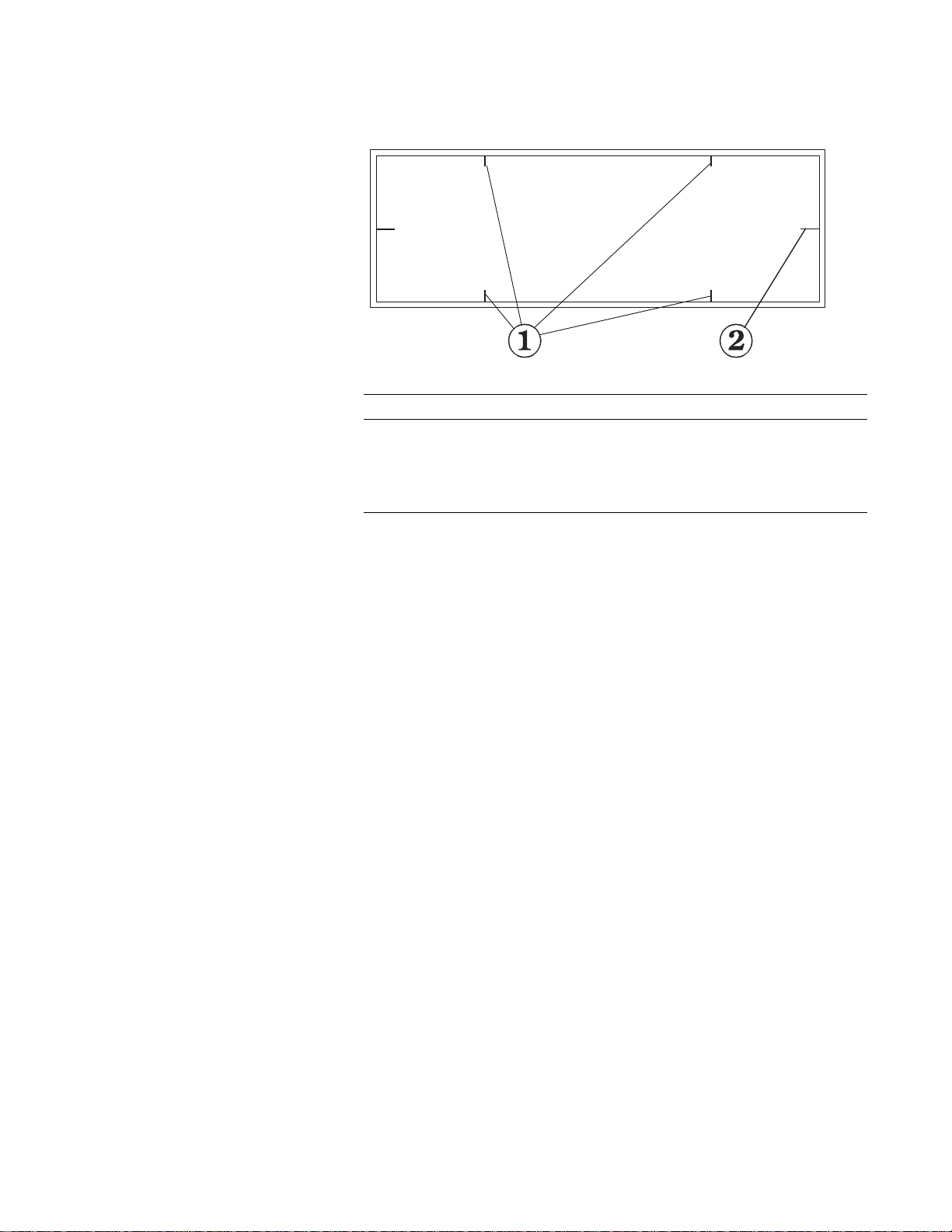
Figure 1-2
KP1068A-0102
Table Pad (typical)
QDR Reference Manual
Table 1-1.
Tab le Pad Guides
Note: The Table Pad markings
vary with the different models.
Item Description Function
1 Scan Limit
2 Center Lines Used to center the patient on the table.
C-Arm
Note: Expl orer C- arm also contai ns
its Control Panel.
X-Ray Source and Detectors
Laser
The C-arm and table drive motors provide the table and arm
motion required to scan the X-ray beam along the patient’s body.
The C-arm contains the X-ray source, X-ray detectors and laser.
The X-rays are generated underneath the table and projected
upward. At the top of the C-arm are detectors that convert the Xrays into electronic data. This data is then sent to the computer
where it is converted to scan images.
The laser projects a red visual cross-hair indicator onto the patient
during the patient positioning procedure. The cross-hair indicator
shows the starting position of the X-ray beam.
border
Indicates the maximum scan range of
the unit. Patient positioning must be
within this border.
Introducing the QDR Series System 1-5
Page 28
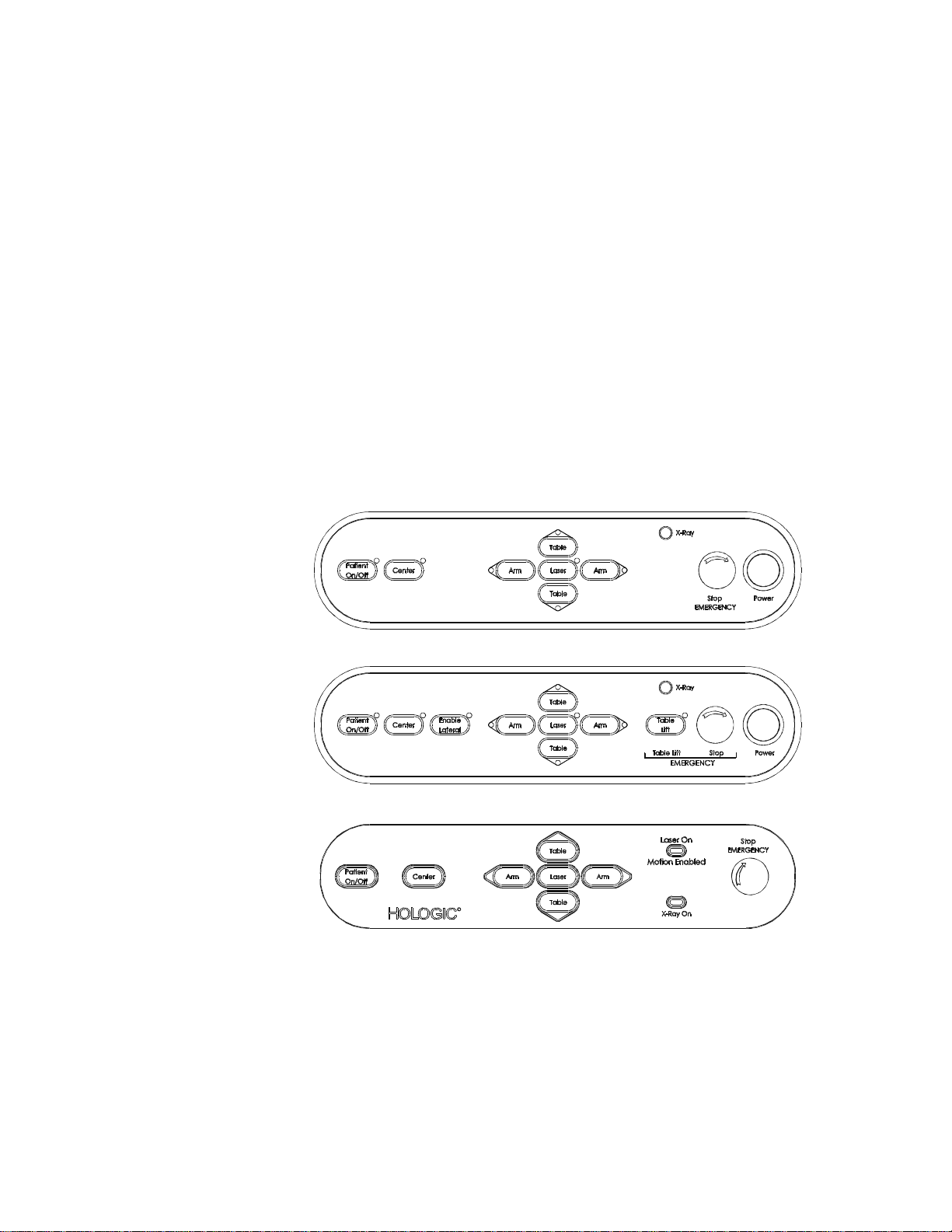
QDR Reference Manual
KP1068A-0402
KP1068A-0403
00158-001
Control Panel for QDR Systems
Note: Refer to Chapter 4 for a
detailed explanation of the
functions of the control panel.
The control panel for the QDR Systems contai n a set of switches
and indicators that control the movement of the table and C-Arm.
This allows the operator to help the patient on and off the table,
and permits accurate positioning of the laser.
Also, an Emergency Stop button allows the operator to halt the
scan at any point that the operator feels that the patient’s safety is
in jeopardy.
The Discovery and Explorer Control Panels
The Discovery control panel is located on the right front of the
examination table. The C, Ci, W and Wi control panel is s hown in
Figure 1-3 and the A and SL control panel is shown in Figure 1-4.
The Explorer control panel is located on the C-Arm and is shown
in Figure 1-5.
Figure 1-3
Discovery C/Ci/W/Wi
Control Panel
Figure 1-4
Discovery A/SL
Control Panel
Figure 1-5
Explorer
Control Panel
Discovery/Explorer Control Panel Switches and Indicators
The Control Panel contains the following switches and indicators:
• C-Arm Controls: Arm (left) and Arm (right) switches
• Table Controls: Table (in) and Table (out) switches
• Laser switch - light blinks when laser is on
1-6 Introducing the QDR Series System
Page 29
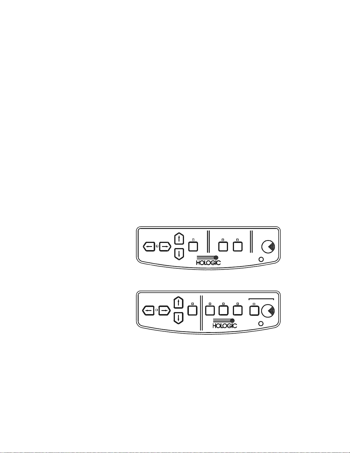
QDR Reference Manual
Stop
X-Ray
Arm
Table
Laser
Center
Table
Patient
On/Off
KP0886-0105
Stop
X-Ray
Arm
Table
Laser
Arm
Table
Laser
Enable
Lateral
Center
Table
Patient
On/Off
Table
Emergency
KP0886-0106
• Center Table switch (also centers the C-arm)
• Patient On/Off switch
• X-ray On indicator
• Emergency Stop button
• Power switch (all models except Explorer)
• Enable Lateral switch (Discovery-A and -SL models only)
• Table Lift switch (Discovery-A and -SL models only)
The QDR 4500 and Delphi Control Panels
Note: Refer to Chapter 4 for a
detailed explanation of the
functions of the control panel.
The control panel allows the operator to control the movement of
the C-arm and table. This helps the patient to easily get on or off
the table, and permits the operator to accurately position the
laser.
Also, an Emergency Stop button allows the operator to halt the
scan at any point that the operator feels that the patient’s safety is
in jeopardy.
The QDR 4500 Control Panels
The QDR 4500 Control Panels are located on the right front of the
examination table unit.
Figure 1-6
QDR 4500 C and W
Control Panel
Figure 1-7
QDR 4500 A and SL
Control Panel
The Delphi Control Panels
The Location of the control panel for the Delphi-C and -W is on
the front of the C-arm, the location of the control panel for the
Delphi-A and -SL is on the right front of the examination table.
The Delphi Control Panels contains a series of switches, buttons,
and indicator lights. The switches control the movements and the
Introducing the QDR Series System 1-7
Page 30
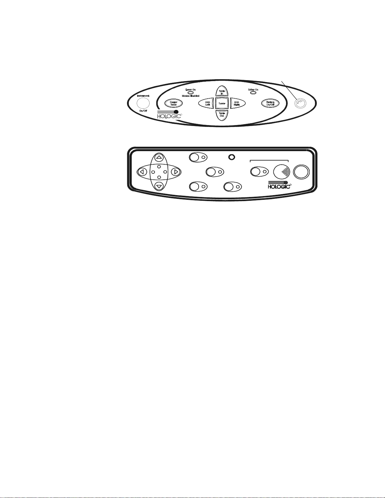
Figure 1-8
R
Emergency
Stop Button
KP0886-0107
EMERGENCY
X-Ray
Patient
On/Off
Table
A
R
M
Table
A
R
M
Laser
Center
Tab le
Enable
Lateral
Table Lift Stop
Power
R
KP0886-0108
Delphi-C and -W
Control Panel
Figure 1-9
Delphi-A and -SL
Control Panel
QDR Reference Manual
indicator lights inform the operator these activities are in
progress.
QDR 4500/Delphi Control Panel Switches and Indicators
The Control Panels contain the following switches and indicators:
This control panel includes:
• C-arm Left and Right switches
• Table In and Out switches
• Laser switch On/Off (light blinks when laser is on)
• Center Table switch (also centers the C-arm)
• Patient On/Off switch
• X-ray On indicator
• Emergency Stop button
• Laser On/Motion Enabled indicator (light blinks when
laser is on, Delphi-C and -W systems only)
• Instrument On/Off (Power) switch (Delphi systems only)
• Enable Lateral switch (4500A and SL, and Delphi-A and SL only)
• Emergency Table (Table Lift) switch (4500A and SL, and
Delphi-A and -SL only)
1-8 Introducing the QDR Series System
Page 31
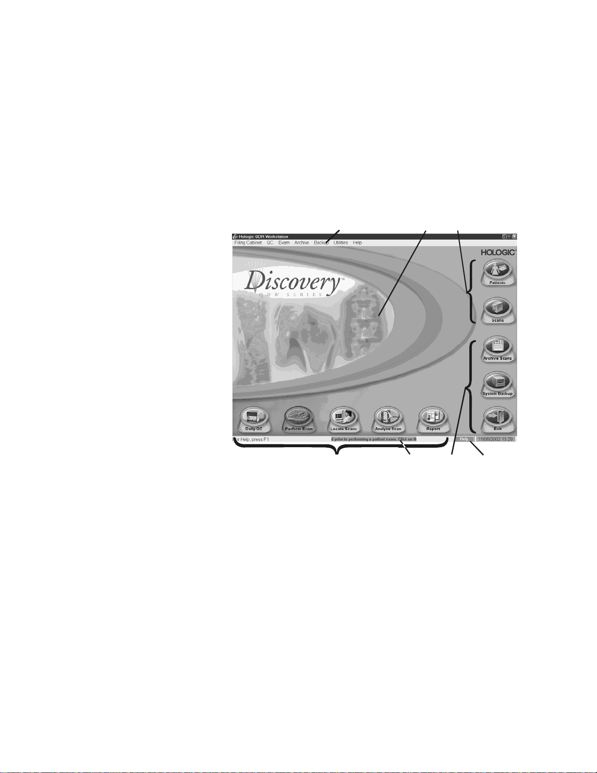
QDR Reference Manual
KP1068A-0103
123
456
7
Introducing the APEX Software
Note: Refer to Chapter 3 for
detailed information about using
APEX software.
The QDR Series uses the Windows® XP operating system. The
computer screens use a graphical user interface (GUI) that are
called windows. The primary interface consists of a main window
with buttons or menus that allow the operator to choose specific
tasks or actions.
Main Window Overview
Figure 1-10
The QDR Series
Main Window
Note: Figure depicts Discovery
Main Window, other models have
slightly different appearance but
the same functions.
Main Window Features
The important features of the main window include:
1 - Menu Bar
The Menu Bar can be used with the mouse or keyboard to
perform or analyze a scan, create or edit patient records and
perform system maintenance functions.
2 - Main Work Area
The Main Work area acts as the holder for all the other windows
or dialog boxes the operator uses when acquiring or analyzing a
scan.
Introducing the QDR Series System 1-9
Page 32

QDR Reference Manual
3 - Filing Cabinet buttons
The Filing Cabinet buttons open the file cabinets that store patie nt
and scan records.
4 - System Function buttons
The System Function buttons start the ma jor system ma intena nce
activities that the operator perform such as archiving (long-term
storage).
5 - System Message ticker tape
The System Message ticker tape provides a moving message
about activities that the operator may need to perform such as
reminding the operator to perform daily QC.
6 - Daily Function buttons
The Daily Function buttons begin five daily activities that the
operator may use to acquire and analyze a scan.
7 - Help
The APEX Online Help system provides step-by-step directions
for using the APEX software. The operator can access online help
by clicking on the Help button (either at the top or bottom of the
main window or on most dialog boxes), or by pressing the F1 key .
Introducing the Quality Control Spine Phantom
Note: Refer to Chapter 5 for
more information about using
the QC Spine Phantom.
Daily quality control procedures ensure that the QDR Series
system functions properly. When the operator performs daily
QC, the spine phantom is scanned. The system adds the results of
the scan to a database, and plots this on a graph. This records a
daily comparison to 10 separate measurements taken at the time
of the system’s inst allation, and provides the basis for the system
calibration.
Continuous, self-calibration is a feature of the QDR series. The
scanner has a calibration drum permanently installed inside the
unit that acts as an internal reference to automatically compe nsate
for variations in the emission from the X-ray source.1 A
calibration factor (CF) is listed on an individual scan report and is
used to identify if a scan was performed before or after a
calibration change or instrument failure.
1. pg. 63, Fogelman, I, Wahner, The Evaluatio n of Osteoporosis: Dual
Energy X-ray Absorptiometry in Clinical Practice, Martin Duntz, UK,
1994
1-10 Introducing the QDR Series System
Page 33

QDR Reference Manual
Knee
Positioner
KP1068A-0105
KP1068A-0106
Velcro
Strap
R
Introducing the Positioning Aids
The QDR Series includes several aids to help the operator
position patients for specific exams. Positioning aids maintain the
correct patient position during the acquisition of a scan. They
include:
• Knee Positioner
• Foot Restraint (hip positioner)
• Head Positioner
Knee Positioner
Figure 1-11
The Knee Positioner
The large knee positioner is placed under the patient’ s lower legs.
This allows positioning of the femurs so that they are as close to
90o to the spine as possible in order to flatten the back. The
operator can rotate the pillow to one of three sides to adjust for
the height of the patient and length of their legs.
Foot Restraint (Hip Positioner)
Figure 1-12
The Foot Restraint
The Foot Restraint (Hip positioner) maintains the correct posi tion
of the femur and minimizes movement during the acquisition of a
hip scan. It is placed between the feet. The foot and leg of the side
being examined are rotated inwards, with the foot against the
Introducing the QDR Series System 1-11
Page 34
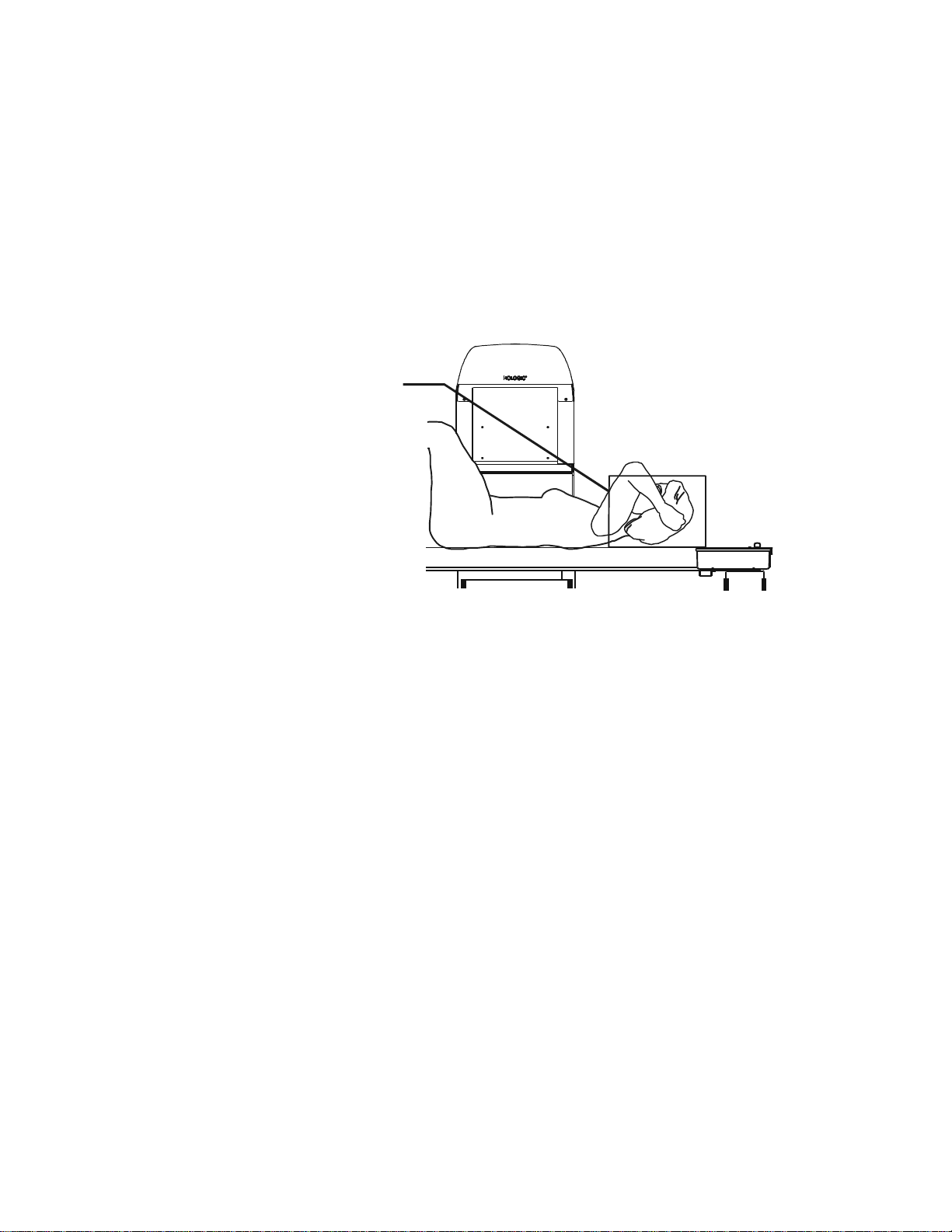
QDR Reference Manual
KP1068A-0108
Head
Positioner
fixture. A strap is placed around the foot, secured in the correct
position.
Head Positioner for A and SL Models
This Head Positioner is supplied on A and SL models and is
placed under the patient’s head for correct positioning during an
AP/Lateral Spine scan. It provides patient comfort to the elevated
arms. The arms must be moved away from the spine for both the
AP and lateral scans.
Figure 1-13
The Head Positioner
for A and SL Models
Introducing the Product Support Materials
The QDR Series systems come with an array of support resources
such as manuals, online help and internet support. These include:
QDR Reference Manual
The QDR Reference Manual (this manual) provides system
technology.
APEX Online Help
The online help system provides step-by-step directions for using
the APEX software. Access online help by clicking on the Help
button (either at the top or bottom of the main window or on most
dialog boxes), or by pressing the F1 key.
QDR Series Technical Specifications Manual
The Technical Specifications Manual provides specifications and
regulatory information for QDR Systems.
1-12 Introducing the QDR Series System
Page 35

QDR Reference Manual
Operator’s Manual
The Discovery and Explorer Operator’s Manuals provide user
instructions and are available in English, French, Italian, German,
Spanish, Brazilian Portuguese, and Polish.
Hologic Internet Site
The Hologic web site (http://www.hologic.com) provides a wide
variety of customer support information including service and
training offerings, FAQ, and contact information.
Information about cyber-security for QDR systems is available on
the Hologic web site at the following URL:
http://www.hologic.com/cc/netwrksec.htm
Introducing the QDR Series System 1-13
Page 36

QDR Reference Manual
1-14 Introducing the QDR Series System
Page 37

Chapter 2
Understanding QDR Series
Technology
This chapter provides explanations of the Quantitative Digital
Radiography application of DXA technology and the scan results
produced by the QDR Series systems.
Content
Subject Page
Introducing Key Elements 2-2
Introducing the Scan Sites 2-4
Lumbar Spine 2-4
Proximal Femur 2-5
Forearm 2-6
Whole Body 2-7
Understanding the Scan Results 2-8
2-1
Page 38

QDR Reference Manual
C
B
KP0886-0201
Introducing Key Elements
To help provide the user with a fundamental understanding of the
operation of the QDR Series system, the key elements are
explained in the following sections:
• Presenting DXA technology (brief description)
• Introducing the scan sites (anatomical sites of the skeleton
areas that are scanned)
• Understanding the scan results (results produced by a scan
that can be interpreted by a physician)
Presenting DXA Technology
Dual Energy Absorptiometry (DXA or DEXA) is a method
utilized to measure bone density. Developed by Hologic in 1987,
these X-ray instruments emit alternating high, 140kVp, and low,
100kVp, X-rays. The first generation Hologic QDR instruments
used a single, or pencil X-ray beam, and a single detector. The
scanner worked by moving the detector and X-ray source in a
rectilinear pattern to acquire data of the lumbar spine and hip.
Continued development of the pencil beam single detector
configuration enabled a second generation of QDR instruments to
measure tissue composition, fat and lean, as well as bone. The
third generation QDR densitometers employ multiple detectors
and a dual energy X-ray fan-beam. The arm moves in a single
direction decreasing scan times from minutes to seconds with
improved image quality and equivalent precision. The beam
sweeps across a region of interest on the scan area in a fan-shaped
pattern, and is detected by a high-resolution multi-detector array
to form a high quality image.
2-2 Understanding QDR Series Technology
Page 39

Accuracy and Precision
Accuracy is the ability to measure the bone mineral density
(BMD) of an object the same as by using an alternate method
such as ashing. Precision is the ability to reproduce the
measurement repeatedly. Independent tests scanning the same
patients on both pencil and fan beam instruments have
demonstrated no significant differences in accuracy . S tudies have
reported a precision of 1% or better for spine, hip, and whole
body measurements when scanned on Hologic instruments.
Principles of Operation
The basic principle of DXA data acquisition is based on the
different bone and soft tissue attenuation characteristics at the two
pulsed X-ray levels. A calibration drum, comprised of known
amounts of bone and soft tissue equivalent materials is placed in
the beam. As the beam passes through the patient, more lower
energy X-rays than higher energy X-rays are absorbed by the
anatomical structures in the patient. The beam is then registered
by the detectors in the C-arm. The raw scan data, containing the
attenuation values of tissue, bone, and the calibration drum are
captured and transferred to a computer. An algorithm interprets
each pixel, creates an image and quantitative measurement of the
bone and body tissues.
QDR Reference Manual
Understanding QDR Series Technology 2-3
Page 40
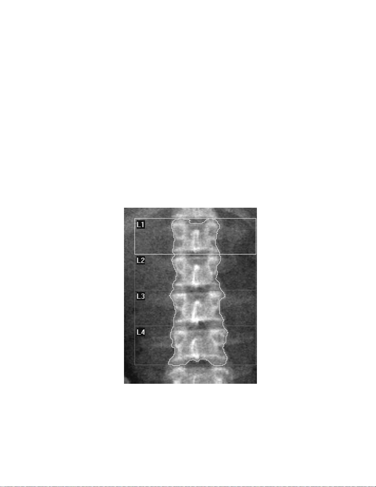
QDR Reference Manual
KP0886-0202
Introducing the Scan Sites
The scan areas that provide the most information about patterns
of bone loss include:
• Lumbar Spine
• Proximal Femur
• Forearm
• Whole Body
Lumbar Spine
The spine consists of a number of vertebrae categorized as
cervical (upper column), thoracic (mid column), lumbar (mid to
lower), and sacrum and coccyx (at the end). Significant bone loss
due to aging or osteoporosis is often observed in the vertebrae,
and particularly in the lumbar area.
The AP Lumbar Spine is the most widely used anatomical site for
the evaluation of osteoporosis. The vertebral bodies, L1 through
L4, contain approximately 40% cortical and 60% trabecular bone.
The high amount of trabecular bone and the relative ease of
2-4 Understanding QDR Series Technology
Page 41
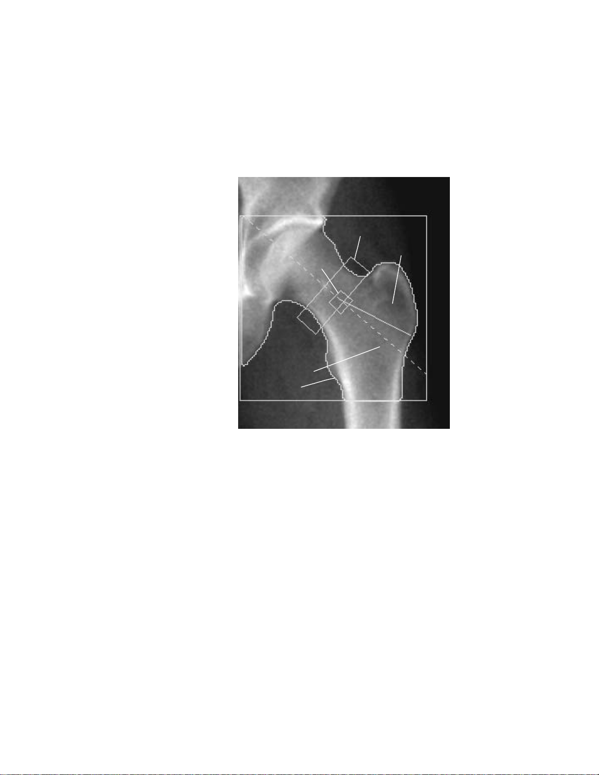
Proximal Femur
Inter-trochanter
Total Hip
Trochanter
Femoral Neck
Ward’s
Triangle
KP0886-0203
QDR Reference Manual
reproducibility of positioning of the spine provide an important
source for baseline bone density data.
The femur is the skeletal site where the most serious
consequences of osteoporosis (fractures) often occur.
BMD results for proximal femur (Hip) scans, are reported for five
different anatomical areas: Total Hip, Femoral Neck, Trochanter,
Inter-Trochanter, and Ward’s Triangle.
• The Total Hip is the most reproducible measurement of
the hip and has become the preferred clinical
measurement of the hip bone mineral density.
• The Femoral Neck region contains a large proportion of
trabecular bone and provides an easily reproducible area
in the hip for DXA scanning. The analysis is completed
by placing a specific region at the anatomical landmark.
That landmark, called the “greater trochanter notch”
permits reproducibility for longitudinal scanning.
• The Trochanter is a triangular region whose boundaries
are the lateral edge of the femur and the inferior edge of
the neck box and the solid line where the edge of the
femur changes curvature below the trochanter.
Understanding QDR Series Technology 2-5
Page 42

Forearm
Carpal Bones
Ulna
Radius
KP0886-0204
QDR Reference Manual
• The Inter-Trochanteric region is below the Femoral
Neck to the bottom edge of the ROI.
• The Ward’s Triangle is located automatically by the
system and places a small box approximately 1cm x 1cm
at the area of minimum density in the femoral neck
region. For some patients, an area of minimum density
cannot be found. When this occurs, the Ward’s Triangle is
automatically centered at the intersection of the femoral
midline and the initial position of the bottom edge of the
femoral neck box.
Bone loss may be notable in the forearm and for this reason it can
be used as a scan site. The forearm scan includes the region of the
radius and ulna and the wrist bones (carpals).
The Ulna is the smaller of the two bones and is located laterally,
or on the “small finger side” of the forearm.
The Radius is larger than the Ulna and allows the rotation of the
forearm. This bone includes an important anatomical structure
described as the “Distal 1/3.” This is an active metabolic bone
site.
The Carpal bones are two rows of small bones also known as the
“Wrist” bones.
2-6 Understanding QDR Series Technology
Page 43
Whole Body
KP0886-0205
QDR Reference Manual
Note: Whole Body is available as
an option on Explorer.
Discovery-A, -W and Wi instruments allow regional and global
measurement of the Whole Body. An advanced application of
QDR technology can directly measure fat and skeletal mass and is
useful in research and clinical studies.
The anatomical
areas analyzed are:
• the head
• the left arm
• the right arm
• the left rib
• the right rib
• the T-spine
• the L-spine
• the pelvis
• the left leg
• the right leg
The subregion
analyzed includes
all of the above
except the head.
Understanding QDR Series Technology 2-7
Page 44

QDR Reference Manual
Understanding the Scan Results
The QDR DXA technology provides accurate and precise
measurement of small changes in bone mineral density (BMD)
measured in grams per centimeter squared (g/cm
BMD measurements offer the physician the most reliable means
of recording the rate of bone loss or gain and estimating a
patient’s risk of fracture.
Z-Score
The Z-score is a measure of the difference between the patient’s
BMD and that of healthy people of the same sex, age and
ethnicity.
T-Score
The T-score is a measure of the difference between the patient’s
BMD and that of a young adult population of the same sex and
ethnicity.
2
). Presently
Reference Database
The reference database represents the average results as a
function of age, sex, and ethnicity for a matched population.
Reference curves specify average BMD, and standard deviation
as a function of age. Each curve applies to a specific scan type,
analysis type, bone region, patient sex, and ethnic group.
Reference database reports use these reference curves for graphic
display, and for the calculation of Z and T scores. Each of these
curves compares a patient scan, or a series of patient’s scans, with
the reference database.
2-8 Understanding QDR Series Technology
Page 45

Chapter 3
APEX Software
The APEX software displays a user interface on the computer screen
that contains both words and pictures. This chapter provides
information on the use of this user interface and its features.
Content
Subject Page
Understanding the Mouse 3-2
Using the Mouse with APEX Software 3-3
Understanding the User Interface 3-4
Understanding Main Window Components 3-7
Introducing the System Software Reminders 3-13
Introducing the System Software Help 3-14
3-1
Page 46

QDR Reference Manual
Understanding the Mouse
A graphical user interface (GUI) is designed so that you can move
easily from step to step with the help of a mouse. The mouse acts
like a keyboard.
The mouse allows you to move a bit faster around a computer
screen than using just the keyboard. Y ou can use a mouse to move
the cursor (arrow) around on the computer screen, and “point” to
different objects.
The “mouse” is shaped so that it is easy for your hand to hold. As
a result, it looks like a mouse with a tail. The tail is the wire that
attaches the device to the computer. Although the look of this
device has changed for some computers over the last several
years, they are still generally referred to as a mouse.
Holding the Mouse
Mouse Tasks
You hold a mouse by covering it with your hand. The mouse-tail
(wire) is positioned up at your fingers with your thumb resting on
the side. Your first finger rests lightly on the left mouse button
and your second finger rests lightly on the right mouse button.
The heel of your hand rests lightly on the back end of the mouse.
This helps you move the mouse more easily.
You can use the mouse:
To... Move the mouse
and point...
Enter text
in a field
Perform an
action
Move an
object on
the desktop
Inside a field Press and release (click) the
Anywhere on a
button in a
window
To the object Press and hold the left mouse
And...
left mouse button once to
insert the cursor into a field
so that you can type text.
Press and release the left
mouse button (click).
button down.
Move the mouse, dragging
the icon to the spot that you
want it to remain.
Release the mouse button.
This is referred to as
dragging and dropping.
3-2 APEX Software
Page 47

QDR Reference Manual
KP0886-0301
Left Mouse
Button
Using the Mouse with APEX Software
The mouse can have two or three buttons. You only need to use
the left mouse button with the APEX software.
Pointing with the Mouse
As you move the mouse, an arrow moves on the screen. Y ou must
point to an object before you can click on it.
Clicking the Mouse
Clicking the mouse means quickly pressing and releasing the left
mouse button. For example, when the instructions indicate to
click the OK button, it means positioning the arrow on the button,
and quickly pressing and releasing the left mouse button once.
Double-Clicking the Mouse
Double-clicking means clicking the left mouse button twice
quickly. Use the double-click function to open another window.
For example, double-clicking on a patient’s name displays the
Patient Record window instead of having to click on the name
once, and then click the OK button.
Dragging and Dropping
Dragging and dropping means pressing and holding the left
mouse button on an object or item, dragging that item to another
area of the screen, and releasing the mouse button.
APEX Software 3-3
Page 48
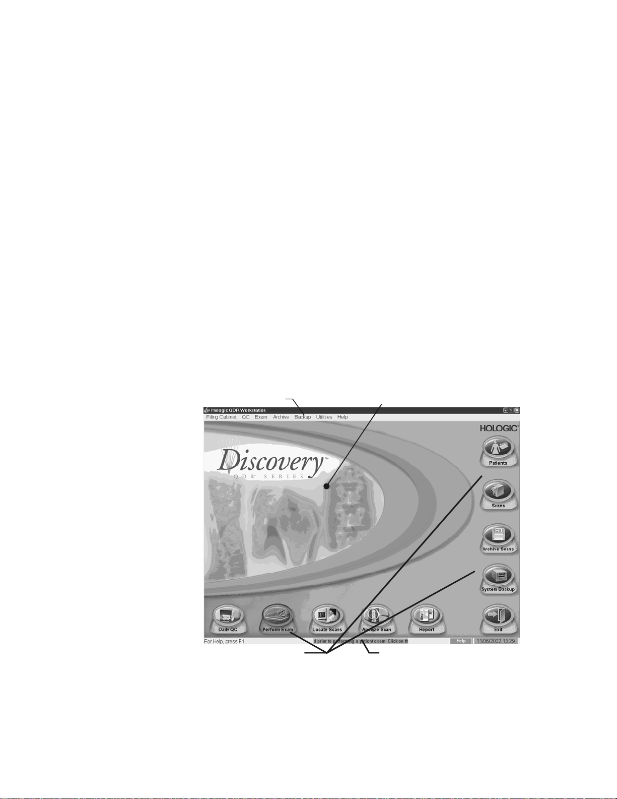
QDR Reference Manual
KP1068A-0302
Menu bar
Main work area
Function Buttons
Ticker Tape
Understanding the User Interface
The user interface refers to the screen displayed on your computer
monitor which is called a “window.” A window contains various
information which can be “opened and closed,” multiple
windows can be opened at the same time.
The User Interface windows contain words and picture such as
buttons and icons. These pictures represent sets of instructions to
the computer that are activated with the mouse.
User Interface Windows
The User Interface windows provide access to different scan
functions using buttons, menus, and a task bar. There are three
basic types of windows:
• Main window
• Tab windows
Main Window
Figure 3-1
The Main Window
Note: Figure depicts Discovery
Main Window, Explorer has
slightly different appearance but
the same functions.
• Dialog windows
3-4 APEX Software
The main window includes function buttons, menu bar and a
ticker tape. It also has a main work area as shown in Figure 3-1.
Page 49

Tab Windows
KP0886-0304
Window Tabs
Search T ext Field
Function Button
Sort List
Scroll Bar
QDR Reference Manual
These windows are generally a series of windows with tabs that
are grouped together because they contain related information.
For example, the “Select a Scan” window is a series of three tabs
that allow you to select unanalyzed scans, analyzed scans, or all
scans.
Figure 3-2
Tab Window
These windows can include:
• Window tabs
• Search Text fields
• Sort lists
• Function buttons
• Scroll Bar
APEX Software 3-5
Page 50
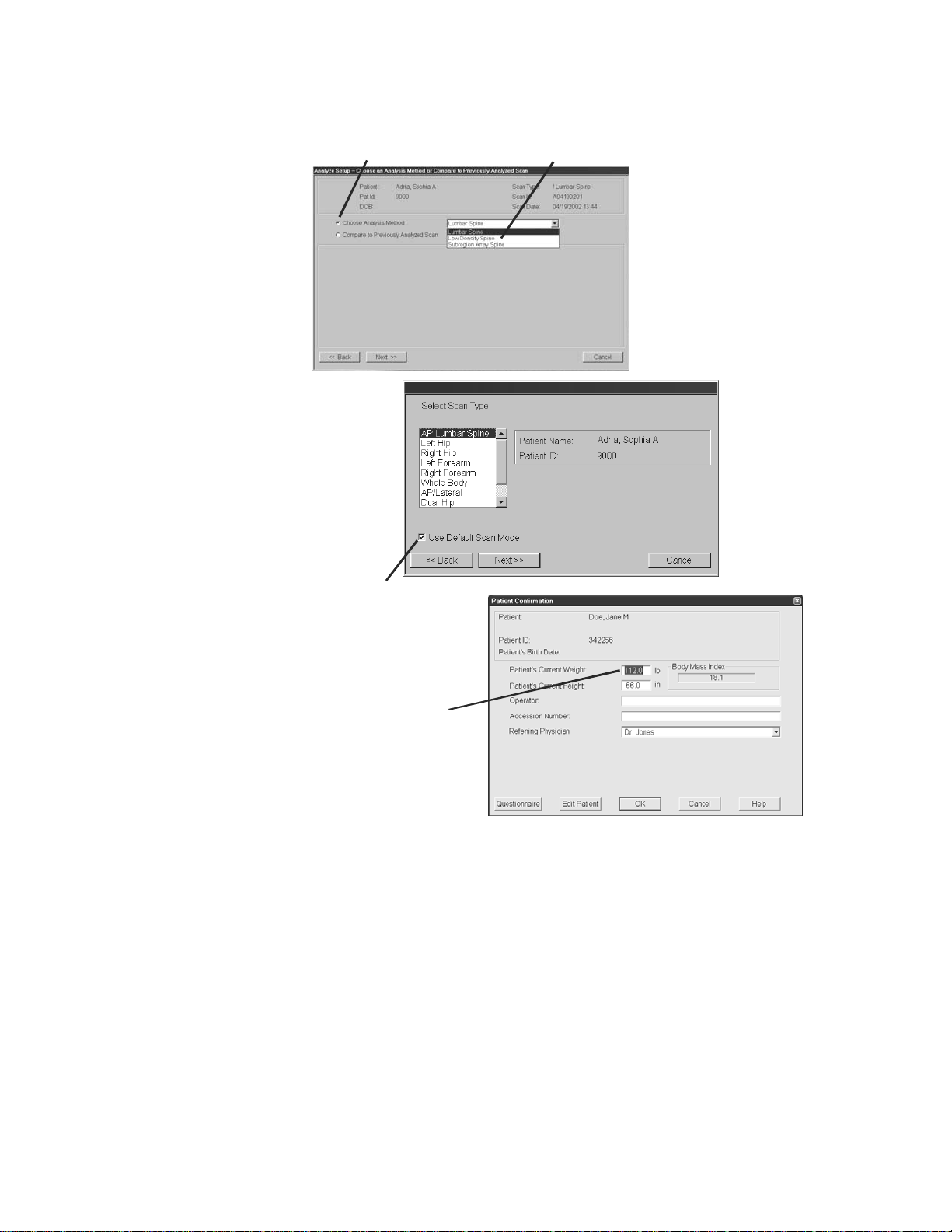
Dialog Windows
Radio Button
Drop Down Menu
Check Box
Text Field
Dialog Windows
QDR Reference Manual
Figure 3-3
3-6 APEX Software
Dialog windows allow you to perform certain actions such as
entering or editing information. For example, the Confirm
window allows you to enter patient’s height, weight, and the
operator’s initials.
These windows include a number of features such as:
• Radio buttons - allow you to choose one, and only one,
item from two or more items
• Drop down lists - allow you to select from a list of items
Page 51

QDR Reference Manual
KP1035A-0307
KP1035A-0309
KP1035A-0311
KP1035A-0313
KP1035A-0315
• Check boxes - allow you to choose the item (box checked)
or not (box unchecked)
• Text fields - allow you to enter text (from keyboard)
Understanding Main Window Components
Each window has unique features that allow you to acquire and
analyze a scan, and store the records for future use.
Main Window Buttons
The main window (see Figure 3-1) provides a series of buttons
that help you perform the primary tasks of the system.
Function Buttons
Button Description
This button initiates the daily QC procedure.
When flashing, indicates that daily QC needs to
be performed before you can begin scanning
patients.
This button initiates the patient exam by
displaying a list of existing patients. You can also
add a new patient record, or edit an existing
patient record.
This button allows you to locate archived scans
and restore them onto the computer. You can also
select a patient to get their biography and
insurance details.
This button initiates Analyze of a specific scan to
generate BMD results.
This button allows you to create, configure, or
print a report for a scan that has already been
analyzed.
APEX Software 3-7
Page 52
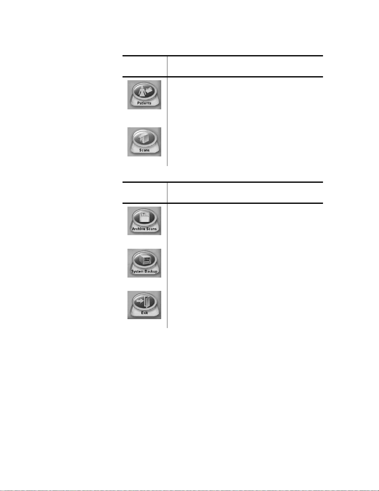
QDR Reference Manual
KP1035A-0317
KP1035A-0319
KP1035A-0321
KP1035A-0323
KP1035A-0325
Filing Cabinet Buttons
Button Description
This button opens the Patient drawer and displays
a list of all patients on the system. You can also
add a new patient record, edit an existing patient
record or input data from any DXA system for
patient follow up.
This button opens the Scan drawer and displays a
list of scans currently on the system. Y ou can also
view scan details of a selected scan.
System Management Buttons
Button Description
Using Menus
Choosing Menu Items
This button initiates saving scan data to selected
media so that it may be restored for later use.
This button initiates back ups of the database in
case of computer failure.
This button initiates exiting the software.
The menus available in the software are listed in the menu bar at
the top of the window. In most cases, you can use the buttons to
perform the same tasks as some of the menu options.
You can choose a menu selection by:
1. Pointing to it with the mouse and clicking on it; or,
2. Pressing and holding the Alt key while typing the underlined
letter in the menu title. For example, from the main window
press Alt+F to open the Filing Cabinet menu, then press
Alt+P to open the Patient drawer.
3-8 APEX Software
Page 53

Using Sub-Menus
KP0886-0327
QDR Reference Manual
Some menu selections display a sub-menu that appears alongside
the parent menu. Menu items that open a sub-menu display with a
right arrow (→) or left arrow (←) symbol. Select an item from a
sub-menu the same way that you select an item from a regular
menu. For example, press Alt + U to open the Utilities menu.
Scroll down to Database T ools, then scroll across to select an ite m
from the sub-menu.
Closing Menus
To close a menu, click anywhere outside of the menu.
Understanding Other Window Components
There are a number of other window components located on the
Tab and Dialog windows that allow you to perform actions that
include:
• Enter text
• Finding records stored in folders with tabs.
• Selecting an item from a list that drops down from a field.
• Selecting functions by turning on and off radio buttons.
• Performing tasks using command buttons.
• Moving up and down through a window using a scroll bar.
• Sorting a list.
• Selecting an item in a list.
Entering Text
Use the Tab key or your mouse to position the cursor into the text
field. Click once inside the text field to begin entering text.
APEX Software 3-9
Page 54

Tabs
KP0886-0328
KP0886-0330
KP0886-0331
Drop-down Lists
QDR Reference Manual
Some dialog boxes in the software have a series of tabs across the
top that let you view specific information. The tabs are similar to
folder tabs in a filing cabinet. Click once on the tab to open that
“folder.”
Radio Buttons
Command Buttons
The dialog box shows a drop-down list for the Spine Analysis.
Clicking on the down arrows displays the list of options from
which to choose. Highlight the desired field and click once.
Radio buttons allow you to pick one choice from a number of
options. Click in the small circle next to the option to select it. In
this example, a “filled” circle indicates that Choose Analysis
Method is the selected choice.
Buttons activate an operation. In a dialog box, for example,
clicking on the Cancel button cancels the operation and closes the
dialog box. Some examples of buttons used in the software
include OK, SelectAll, DeselectAll, Cancel, Close, Next, Back.
3-10 APEX Software
Page 55
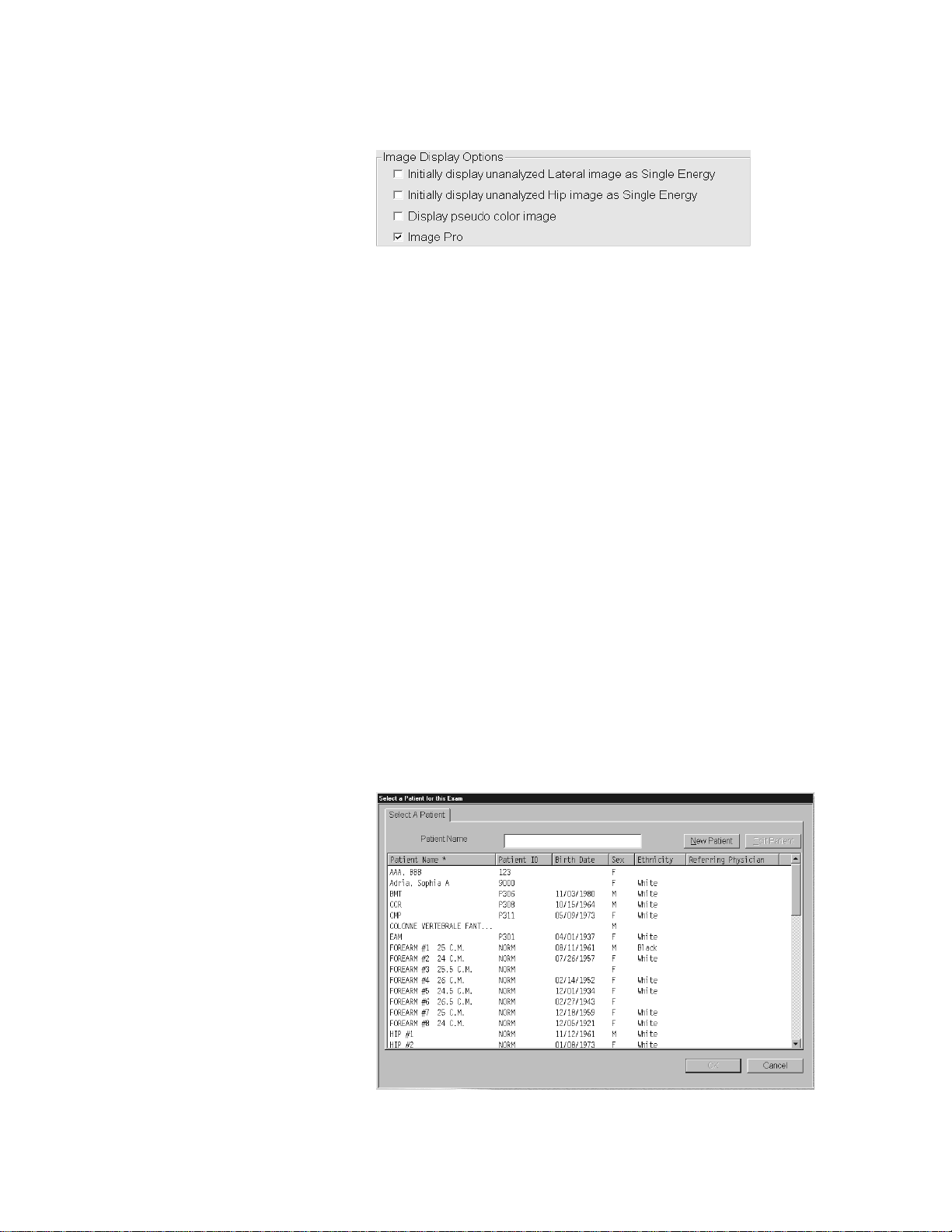
Check Boxes
KP1035A-0331a
KP0886-0332
Scroll Bars
QDR Reference Manual
Check Boxes appear in various menus and are used to select one
or more items in a list.
Scroll bars appear on the right and bottom edges of some screens.
Use the scroll bars to view portions of the window that are not
entirely visible.
View hidden portions of the screen by clicking on the arrows at
either end of the scroll bar, or by dragging the slider box between
the arrows.
Sorting List Items
Identifying the Sort Order
The horizontal scroll bar moves the contents within the window
left and right. The vertical scroll bar moves the contents of the
window up and down.
The software displays screens with listings such as patient data,
scan data, and so on. This section provides helpful hints on
changing the sort order of lists, as well as selecting items from a
list.
APEX Software 3-11
Page 56

QDR Reference Manual
An asterisk (*) in the heading identifies the sort order. For
example, an asterisk in the Patient heading indicates the sort order
is alphabetical by the patient’s last name.
Changing the Sort Order
You can change the sort order of listed items by clicking on the
heading above the item. For example, to sort the list by Patient
ID, click on Patient ID.
Selecting Items From a List
Selecting One Item
To select one item from a list, click on the item and the item
becomes highlighted. Then click OK to select that item.
Selecting Multiple Items
To select multiple items from a list, click on the first item, then
press and hold down the Ctrl key while clicking on subsequent
items. Selected items are highlighted. Release the Ctrl key and
click OK.
Selecting a Range of Items
T o select a range of items, click on the first item in the range , then
press and hold the Shift key and click on the last item. Selected
items are highlighted. Release the Shift key and click OK.
3-12 APEX Software
Page 57

QDR Reference Manual
KP1035A-0307
KP1035A-0323
Introducing the System Software Reminders
The software interface includes visual software aids and functions
to:
• Remind you to perform a certain task
• Show you the function of a button before you click on it
• Let you get help on a certain function or task
• View important system messages
Flashing Buttons
Flashing buttons indicate that you need to perform a task before
you can proceed with daily operations or that you are in danger of
losing unsaved information.
Daily QC
System Backup
When the Daily QC button is flashing, it indicates
that you must perform QC before performing an
examination. Refer to Chapter 5, Quality Control ,
for detailed instructions for performing daily QC.
When the System Backup button is flashing, it
indicates that you need to perform a system
backup. Backing up the system is a weekly
procedure for ensuring that your data is protected
in the event of a system failure. You can still
perform your daily operations, but you should
perform the system backup (by clicking the
System Backup button), as soon as possible.
APEX Software 3-13
Page 58
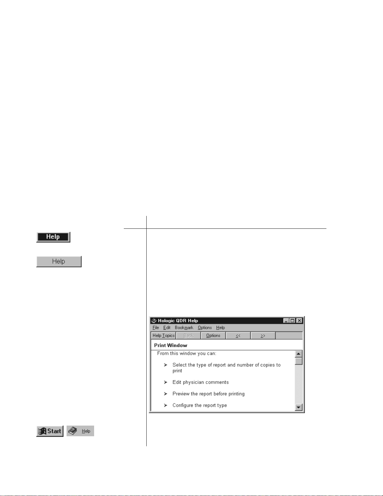
QDR Reference Manual
KP0886-0333
KP0886-0334
KP0886-0335
KP0886-0336
Introducing the System Software Help
APEX has many tools to help you run the software. Some of them
are:
• Tool Tips
• Online context sensitive help
• Ticker Tape messages
Tool Tips
Tool tips appear when you position the mouse pointer over a
button. A small rectangle appears with a description of the button.
You do not need to click the button to view the tool tip.
Online Context Sensitive Help
This feature gives you help on the active window, that is the
window or dialog box you are currently using.
To use Context Sensitive Help:
Step Action
1 If the blue Help button (see left) is visible, click it to get
help on the window that you are working on.
2 If the blue Help button is not visible, look for a Help button
on the currently open window.
3 Click Help if the button is there.
In either case, a screen similar to the one below appears.
The online help is standard Windows help and operates the
same.
You can learn more about Windows help by clicking Start
on the Windows Task bar and selecting Help.
3-14 APEX Software
Page 59

Ticker Tape
KP0886-0337
QDR Reference Manual
The ticker tape appears at the bottom of the main window. It
displays helpful information, or instructions to remind you to
perform a specific task. For example, the ticker tape message
“Click on the System Backup button to start the...” displays,
along with a flashing System Backup button to remind you to
perform a system backup.
APEX Software 3-15
Page 60

QDR Reference Manual
3-16 APEX Software
Page 61

Chapter 4
Performing Daily System
Operations
This chapter provides information about the basic operating
procedures for the Discovery, Explorer, QDR 4500 and Delphi
systems including:
• Turning the System On and Off.
• Switches and indicators for daily system operation.
• Emergency procedures.
Content
Subject Page
Discovery Systems 4-2
Discovery Circuit Breaker and Indicator 4-2
Discovery-C, -Ci, -W and -Wi Control Panel 4-2
Discovery-A and -SL Control Panel 4-4
Turning Discovery Power On and Off 4-5
Discovery Emergency Procedures 4-7
Explorer Systems 4-9
Explorer Circuit Breaker and Indicator 4-9
Explorer Control Panel 4-9
Turning Explorer Power On and Off 4-10
Explorer Emergency Procedures 4-11
QDR 4500 Systems 4-14
QDR 4500 Power Module 4-14
QDR 4500 Control Panel 4-15
Turning QDR 4500 Power On and Off 4-18
QDR 4500 Emergency Procedures 4-20
Delphi Systems 4-23
Delphi AC Power Isolation Module 4-23
Delphi Control Panels 4-23
Turning Delphi Power On and Off 4-26
Delphi Emergency Procedures 4-28
4-1
Page 62
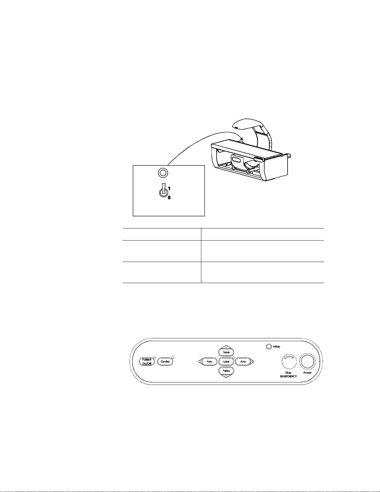
QDR Reference Manual
KP1068_002-0401
MAN-00175_002-0401
Discovery Systems
Discovery Circuit Breaker and Indicator
The Discovery circuit breaker and indicator are located on the
back of the left pedestal (see Figure 4-1). Table 4-1 gives the
description and function of the circuit breaker and indicator.
Figure 4-1
Location of Discovery Circuit
Breaker and Indicator
Table 4-1
Discovery Circuit Breaker
and Indicator
Description Function
Circuit Breaker Turns the power to the Discovery
system off (0) and on (1).
Indicator Glows green when the circuit breaker is
in the on (1) position.
Discovery-C, -Ci, -W and -Wi Control Panel
The Discovery-C, -Ci, -W and -Wi Control Panel (see figure
below) is located on the right front of the examination table. Table
4-2 gives the description and function of the switches and lamps.
Figure 4-2
Discover-C, -Ci, -W and -Wi
Control Panel
4-2 Performing Daily System Operations
Page 63

QDR Reference Manual
Table 4-2
Discovery-C, -Ci, -W and -Wi
Control Panel Switches and
Lamps
Switch/Lamp Function Lamp Indicators
Patient On/Off The table moves to the
front-most position and
the C-arm moves to the
left-most position
Center Moves the table and C-
arm to the center
position
Arm (right) Moves the C-arm to the
right (towards the head
of the table)
Table (in) Moves the table toward
the back
Laser Turns the laser cross-
hair indicator ON or
OFF
When the laser is
ON the Laser On/
Motion Enabled
green indicator
blinks
Arm (left) Moves the C-arm to the
left (towards the foot of
the table)
Table (out) Moves the table toward
the front
EMERGENCY
Stop Button
Pressing this button
stops scanning
immediately. Pressing
the button down and
turning it to the right
resumes normal
operation.
X-Ray
(amber indicator)
Power Turns the power to the
instrument on or off
When X-rays are
being produced this
indicator is ON
When the indicator
is green, power is
ON in the
instrument
Performing Daily System Operations 4-3
Page 64
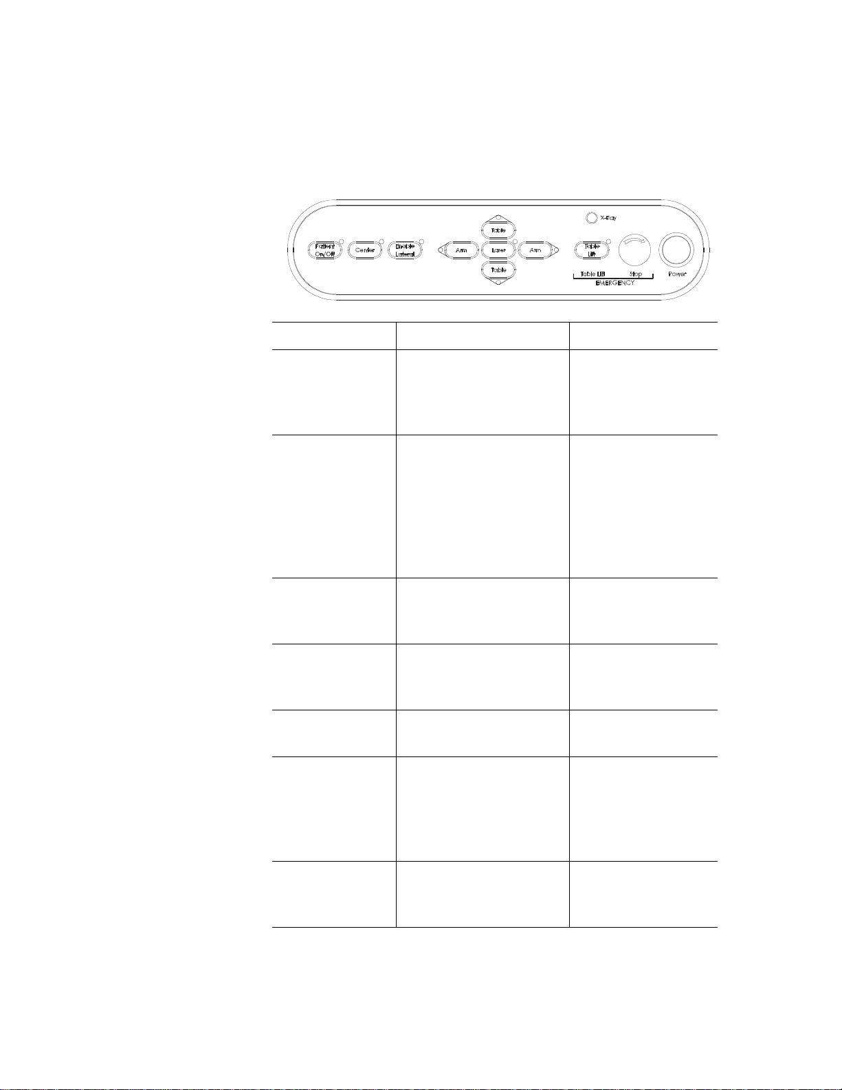
QDR Reference Manual
MAN-00175_002-0403
Discovery-A and -SL Control Panel
The Discovery-A and -SL Control Panel (see Figure 4-3) is
located on the right front of the examination table. T able 4-3 gives
the description and function of the switches and lamps.
Figure 4-3
Discovery-A and -SL
Control Panel
Table 4-3
Discovery-A and -SL Control
Panel Switches and Lamps
Switch/Lamp Function Lamp Indicators
Patient On/Off The table moves to the
front-most position and
the C-arm moves to the
left-most position
Enable Lateral Enables the C-arm and
table to move for the
acquisition of the AP/
Lateral Spine scan. The
Light Blinking ON
= You need to
perform a task as
instructed.
system instructs you
how and when to use
this switch.
Center Moves the table and C-
arm to the center
position
Arm (right) Moves the C-arm to the
right (towards the head
of the table)
Table (in) Moves the table toward
the back
Laser Turns the laser cross-
hair indicator ON or
OFF
When the laser is
ON the Laser On/
Motion Enabled
green indicator
blinks
X-Ray (amber
indicator)
When X-rays are
being produced this
indicator is ON
4-4 Performing Daily System Operations
Page 65

QDR Reference Manual
Arm (left) Moves the C-arm to the
left (towards the foot of
the table)
Table (out) Moves the table toward
the front
EMERGENCY
Table Lift
EMERGENCY
Stop Button
Moves the table up
when pressed.
Pressing this button
stops scanning
immediately. Pressing
the button down and
turning it to the right
resumes normal
operation.
Power Turns the power to the
instrument on or off
Turning Discovery Power On and Off
Do not use the circuit breaker on the back of the left pedestal (see
Figure 4-1) to turn the power on or off. If the green indicator light
above the circuit breaker goes out while the system is running or
if the indicator is not on at the beginning of the day, refer to the
“Discovery Emergency Procedures” on page 4-7.
Light ON = Enabled
when you press the
Emergency Stop
switch.
When the indicator
is green, power is
ON in the
instrument
Beginning of the Workday
Perform the following steps at the start of each workday to turn
the Discovery System on.
Step Action
Performing Daily System Operations 4-5
1 Verify that the green indicator on the back of the left
pedestal is on (Figure 4-1).
This light indicates that the system is receiving AC power.
2 On the Control Panel (see “Discovery-C, -Ci, -W and -Wi
Control Panel” on page 4-2 or “Discovery-A and -SL
Control Panel” on page 4-4). press the Power button.
The Power green indicator illuminates.
Page 66
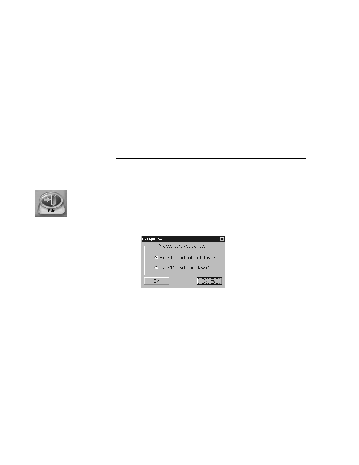
QDR Reference Manual
KP1035A-0325
KP1068A-0404
Step Action
Note: Because the computer and
peripherals may vary, refer to
documentation that came with the
Discovery System for controls
and indicators on the computer,
monitor and printers.
End of the Work day
3 On the Operator Console, turn the computer on.
The monitor (in power save mode) and printer(s) should
already be on during a normal day’s power-up.
The computer boots itself and starts Windows XP. It then
starts the APEX software automatically. If there are any
problems, warning messages will tell you what to do.
Perform the following steps at the end of each workday to turn the
Discovery System off.
Step Action
1 Make sure only the Main Window appears on the monitor.
This is to ensure that you are not in the middle of any
function and all activity has stopped.
2 Click Exit.
The Exit button is in the lower right-hand corner of the
screen.
3 In the Exit QDR System dialog box that appears, select
“Exit QDR with shutdown?” and click OK.
This shuts down the APEX software, and the Windows XP
operating system
4 On the computer, press the power on/off switch to power
off the computer.
5 Turn off the Discovery System by pressing the Power
switch on the control panel (see “Discovery-C, -Ci, -W
and -Wi Control Panel” on page 4-2 or “Discovery-A and
-SL Control Panel” on page 4-4).
The green indicator in the Power button goes out.
Important: Do not turn off the
circuit breaker on the back of the
left pedestal (see Figur e 4-1). The
green indica to r sh oul d remain on.
4-6 Performing Daily System Operations
Do not turn off the printer(s).
Do not turn off the monitor. It goes into power save mode
when the computer shuts down.
Page 67

QDR Reference Manual
Discovery Emergency Procedures
While operating the Discovery there are three emergency
situations that may require your action:
• A facility power failure occurs
• Equipment fails while in operation
• System is turned off
Operator Action During a Power Failure
If the facility power fails, it is a good idea to turn off all the
equipment. When the power returns, frequently it is not stable and
can spike up and down for a few moments. Y ou should wait a few
minutes after power returns to turn on the equipment.
Shutting Down During a Power Failure
Step Action
Note: Refer to documentation
that came with the system for
controls and indicators on the
computer, monitor and printer.
After Power is Restored
1 If the system was in operation when the power failure
occurred, assist the patient from the table
The Patient On/Off switch will be inoperative at this time.
2 Turn off the computer.
3 Turn off the circuit breaker (see Figure 4-1).
Since this is a power failure condition, the gr een Indicator
should already be off.
Step Action
1 After waiting a few minutes for the facility power to
stabilize,
Turn on the circuit breaker.
The green indicator light above the circuit breaker goes
on.
2 Turn the computer on.
3 Perform the procedure in “Beginning of the Workday” on
page 4-5).
If Equipment Fails While in Operation
If the operator determines that the equipment has malfunctioned
(e.g., X-Ray is on and C-arm is not moving) perform the
following procedure.
Performing Daily System Operations 4-7
Page 68

QDR Reference Manual
Emergency Stop Procedure:
Step Action
1 On the Control Panel, press the red Emergency Stop
Button.
The table and the C-arm immediately stop moving, and the
X-rays and laser turn off.
2 Assist the patient off the table.
Note: The power should not be
restored without consulting
Hologic.
3 Turn off the circuit breaker (see Figure 4-1).
4 Disconnect the power cord from the AC outlet (if
possible).
5 Call Hologic customer service.
If AC Power has been Turned Off
If for any reason the circuit breaker has been turned off (not
because of an equipment failure), or the plug has been pulled
from the wall, use the following procedure to apply power to the
system:
Applying power to the system:
Step Action
1 If necessary, place the power cord into the AC outlet.
Note: If the system does not turn
on, make sure that the power cor d
is plugged into the wall. If it is,
call Hologic customer service.
2 Place the circuit breaker in the 1 (on) position (see
Figure 4-1).
The green Indicator above the circuit breaker illuminates.
3 Perform the procedure in “Beginning of the Workday” on
page 4-5
4-8 Performing Daily System Operations
Page 69

QDR Reference Manual
00132-001
MAN-00175_002-0401
Explorer Systems
Explorer Circuit Breaker and Indicator
The circuit breaker and indicator, on Explorer, are located on the
Power Module (see Figure 4-4). Table 4-4 gives the description
and function of the circuit breaker and indicator.
Figure 4-4
Location of Explorer Circuit
Breaker and Indicator
Table 4-4
Explorer Circuit Breaker
and Indicator
Description Function
Circuit Breaker Turns the power to the Explorer system
Indicator Glows green when the circuit breaker is
Explorer Control Panel
Figure 4-5
Explorer Control Panel
Table 4-5
Explorer Control Panel
Switches and Lamps
Switch/Lamp Function Lamp Indicators
Patient On/Off The table moves to the
off (0) and on (1).
in the on (1) position.
The Explorer Control Panel (see Figure 4-5) is located on the CArm. Table 4-5 gives the description and function of the switches
and lamps.
front-most position
Center Moves the table to the
center position
Performing Daily System Operations 4-9
Page 70

QDR Reference Manual
Arm (right) Moves the C-arm to the
right (towards the head
of the table)
Table (in) Moves the table toward
the back
Laser Turns the laser cross-
hair indicator ON or
OFF
Arm (left) Moves the C-arm to the
left (towards the foot of
the table)
Table (out) Moves the table toward
the front
EMERGENCY
Stop Button
Press this button to
immediately stop
scanning. Press the
button down and turn it
to the right to resume
normal operation.
X-Ray
(amber indicator)
When the laser is
ON the Laser On/
Motion Enabled
green indicator
blinks
When X-rays are
being produced this
indicator is ON
Turning Explorer Power On and Off
Do not use the circuit breaker on the Power Module (see
Figure 4-4) to turn the power on or off. If the green indicator light
above the circuit breaker goes out while the system is running or
if the indicator is not on at the beginning of the day, refer to the
“Explorer Emergency Procedures” on page 4-11.
Beginning of the Workday
Perform the following steps at the start of each workday to turn
the Explorer on.
Step Action
4-10 Performing Daily System Operations
1 Verify that the green indicator on the Power Module is on
(Figure 4-4).
This light indicates that the system is receiving AC power.
Page 71

QDR Reference Manual
KP1035A-0325
KP1068A-0404
Step Action
Note: Because the computer and
peripherals may vary, refer to
documentation that came with the
Explorer System for controls and
indicators on the computer,
monitor and printers.
End of the Work day
2 On the Operator Console, turn the computer on.
The monitor (in power save mode) and printer(s) should
already be on during a normal day’s power-up.
The computer boots itself and starts Windows XP. It then
starts the APEX software automatically. If there are any
problems, warning messages will tell you what to do.
Perform the following steps at the end of each workday to turn the
Explorer off.
Step Action
1 Make sure only the Main Window appears on the monitor.
This is to ensure that you are not in the middle of any
function and all activity has stopped.
2 Click Exit.
The Exit button is in the lower right-hand corner of the
screen.
3 In the Exit QDR System dialog box that appears, select
“Exit QDR with shutdown?” and click OK.
This shuts down the APEX software, and the Windows XP
operating system
4 On the computer, press the power on/off switch to power
off the computer.
Important: Do not turn off the
circuit breaker on the Power
Module. The green indicator
should remain on.
Do not turn off the printer(s).
Do not turn off the monitor. It goes into power save mode
when the computer shuts down.
Explorer Emergency Procedures
While operating the system there are three emergency situations
that may require your action:
Performing Daily System Operations 4-11
Page 72

QDR Reference Manual
• A facility power failure occurs
• Equipment fails while in operation
• System is turned off
Operator Action During a Power Failure
If the facility power fails, it is a good idea to turn off all the
equipment. When the power returns, frequently it is not stable and
can spike up and down for a few moments. Y ou should wait a few
minutes after power returns to turn on the equipment.
Shutting Down During a Power Failure
Step Action
1 If the system was in operation when the power failure
occurred, assist the patient from the table
The Patient On/Off switch will be inoperative at this time.
2 Turn off the computer.
Note: Refer to documentation
that came with the system for
controls and indicators on the
computer, monitor and printer.
3 Turn off the circuit breaker (see Figure 4-4).
Since this is a power failure condition, the gr een Indicator
should already be off.
After Power is Restored
Step Action
1 After waiting a few minutes for the facility power to
stabilize,
Turn on the circuit breaker (see Figure 4-4).
The green indicator light above the circuit breaker goes
on.
2 Turn the computer on.
3 Perform the procedure “Beginning of the Workday” on
page 4-10.
If Equipment Fails While in Operation
If the operator determines that the equipment has malfunctioned
(e.g., X-Ray is on and C-arm is not moving) perform the
following procedure.
4-12 Performing Daily System Operations
Page 73

QDR Reference Manual
Emergency Stop Procedure:
Step Action
1 On the Control Panel, press the red Emergency Stop
Button (see Figure 4-5).
The table and the C-arm immediately stop moving, and the
X-rays and laser turn off.
2 Assist the patient off the table.
Note: The power should not be
restored without consulting
Hologic.
3 Turn off the circuit breaker.
4 Disconnect the power cord from the AC outlet (if
possible).
5 Call Hologic customer service.
If AC Power has been Turned Off
If for any reason the circuit breaker has been turned off (not
because of an equipment failure), or the plug has been pulled
from the wall, use the following procedure to apply power to the
system:
Applying power to the system:
Step Action
1 If necessary, place the power cord into the AC outlet.
Note: If the system does not turn
on, make sure that it has power
(that is, the cord is plugged into
the wall). If it is, call Hologic
customer service.
2 Place the circuit breaker in the 1 (on) position (see
Figure 4-4).
The green Indicator above the circuit breaker illuminates.
3 Perform the procedure “Beginning of the Workday” on
page 4-10.
Performing Daily System Operations 4-13
Page 74
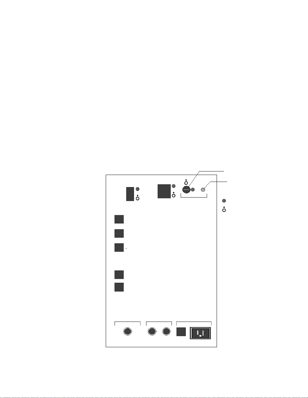
QDR Reference Manual
CB7
CB9
3A 3A 3A
15VAC max 3A
CB8
6A
CB6
X-Ray Supply Pedesta ls X-Ray Emission In d.
CB5
28VDC
10A
3A
1A
4A
10A
CB4
24VDC
CB3
n15VDC Supply
CB2
24/28VDC Supply
CB1
Computer
Computer
Power
Instrument
Power
X-Ray Enable
Key Switch
Indicator
ON
OFF
KP0886-0401
QDR 4500 Systems
QDR 4500 Power Module
The Power Module supplies electrical power to the QDR 4500
system and is located below the workstation table. The Power
Module right side and back panel include on/off switches, circuit
breakers, X-ray key and lamp indicators.
QDR 4500 Power Module Side Panel
The Power Module side panel contains the computer on/off
switch, the instrument power switch, the X-ray enable key, and
most of the circuit breakers (See Figure 4-6 and Table 4-6). These
circuit breakers protect different parts of the system. Under
normal operating conditions, these circuit breakers should remain
on. Under normal circumstances you will not have to take any
action with the circuit breakers.
Figure 4-6
QDR 4500 Power Module
Side Panel
4-14 Performing Daily System Operations
Page 75
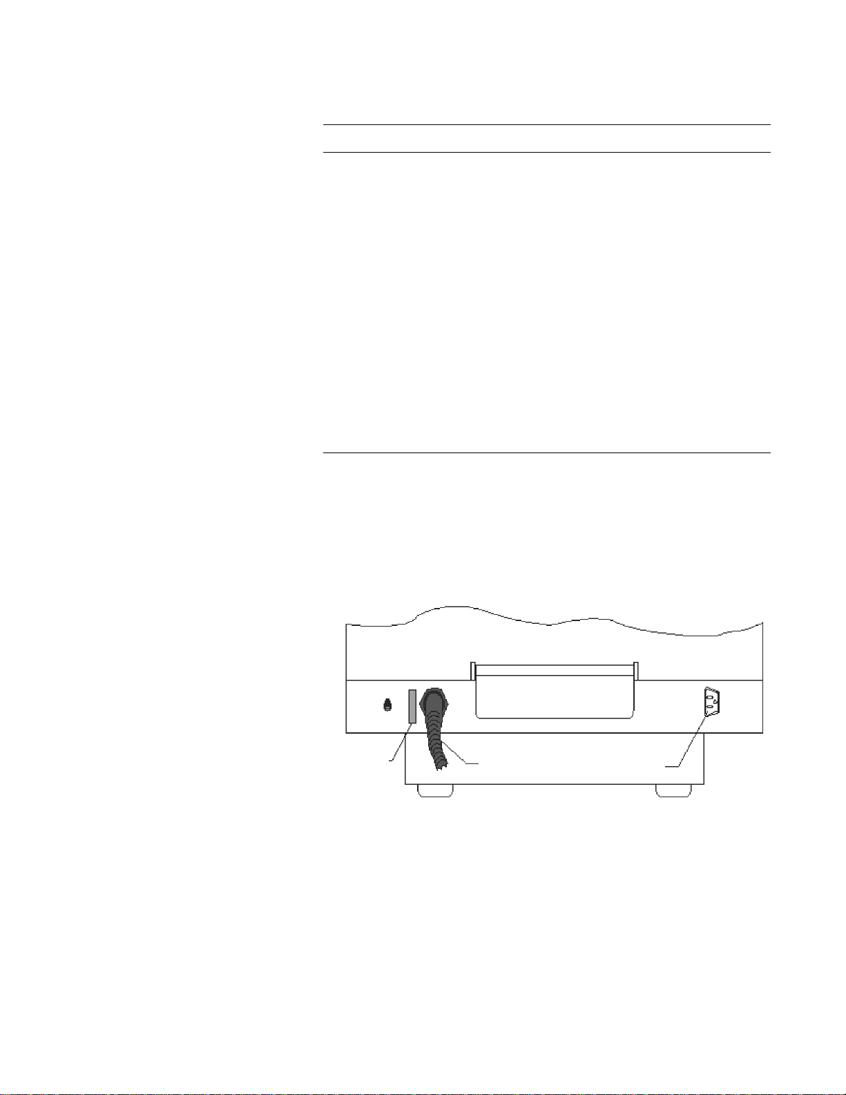
QDR Reference Manual
Power
Indicator
CB1
Main
Power
Main
Power
Cord
1 15VAC max 10A
To Power Strip
KP0886-0402
The functions of the switches and indicators are:
Table 4-6
QDR 4500 Power Module
Components
Description Function
Computer Power Switch Turns the computer, monitor, and
Instrument Power
Switch
X-ray Enable Key Enables or disables X-ray generation.
X-ray Enable Lamp When lit, indicates that X-rays can be
Circuit breakers Only used by the operator if there are
X-ray Emissions Ind. You can use this outlet to enable an
QDR 4500 Power Module Rear Panel
Note: Refer to page 4-20 for m ore
information about operator
actions duri ng a power failure.
The main power switch (CB1) is located on the rear panel of the
power module. It is generally used only after a power failure, to
turn the system OFF and then ON.
printer ON and OFF.
Turns the QDR 4500 instrument ON
and OFF.
generated.
problems with the power supply to
different areas of the system.
indicator light (an X-ray warning light)
such as a red light bulb.
Figure 4-7
Power Module Rear
Panel
QDR 4500 Control Panel
Note: The QDR 4500C and
QDR 4500W Contr ol Pan els do
not include an Enable Lateral
or Emergency Table switch.
The Control Panel, located on the right of the examination table
unit, allows you to direct the movement of the C-arm and table, and
turn on the laser. This means you can move the C-arm to correctly
position the laser. You can also position the C-arm and table so that
the patients can easily get on or off the table.
Performing Daily System Operations 4-15
Page 76

QDR Reference Manual
Stop
X-Ray
Arm
Table
Laser
Center
Table
Patient
On/Off
KP0886-0105
QDR 4500C and QDR 4500W Control Panel
Figure 4-8
QDR 4500C and W
Control Panel
This Control Panel has a series of buttons to move the table, Carm, and turn the laser cross-hair indicator on or off. Indicator
lights verify that components are on or enabled (see Figure 4-8
and Table 4-7). An Emergency Stop button allows the operator to
halt the scan at any point that the operator feels that the patient’s
safety is in jeopardy.
Table 4-7
QDR 4500C and W Control
Panel Switches and Lamps
Switch/Lamp Function Lamp Indicators
Arm ← → Moves the C-arm left or
right.
Light ON = C-arm is
moving either left or
right.
Table ↑↓ Moves the table in or
out
Laser Turns the laser cross-
hair indicator on or off
Light ON = Table is
moving in or out.
Light Blinking ON
= The laser is on. It
will automatically
turn off after several
seconds.
Center Table Moves the table and C-
arm to the center
position
Light Blinking ON
=Table and C-arm
moving to the center
position.
Patient On/On Moves the table and C-
arm to the patient on/off
position
Light Blinking ON
= Table and C-arm
moving to the
patient on/off
position.
X-ray on Lamp Light ON = X-rays
being produced.
4-16 Performing Daily System Operations
Page 77
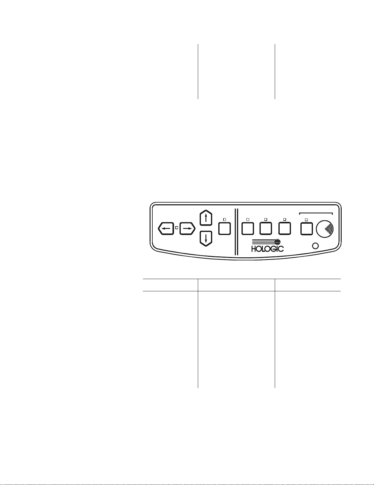
QDR Reference Manual
KP0886-0404
Stop
X-Ray
Arm
Table
Laser
Arm
Table
Laser
Enable
Lateral
Center
Table
Patient
On/Off
Table
Emergency
Emergency Stop
button
Pressing button stops
scanning immediately.
Pressing the button
down and turning it to
the right resumes
normal operation.
QDR 4500A and QDR 4500SL Control Panel
This Control Panel has a series of buttons to move the table, Carm, and turn the laser cross-hair indicator on or off (see Figure 49 and Table 4-8). This control panel also includes an Enable
Lateral button to move the C-arm and table into position for the
acquisition of the AP/Lateral Spine scan. Indicator lights verify
that components are on or enabled. There are two emergency stop
buttons. One button shuts down the system whenever the operator
feels the patient’s safety is in jeopardy. The other stops table
movement.
Figure 4-9
QDR 4500A and SL
Control Panel
Table 4-8
QDR 4500A and SL Control
Panel Switches and Lamps
Switch/Lamp Function Lamp Indicators
Arm ← → Moves the C-arm le ft or
right.
Light ON = C-arm is
moving either left or
right.
Table ↑↓ Moves the table in or
out.
Laser Turns the laser cross-
hair indicator on or off.
Light ON = Table is
moving in or out.
Light Blinking ON
= The laser is on. It
will automatically
turn off after several
seconds.
Performing Daily System Operations 4-17
Page 78

QDR Reference Manual
Enable Lateral Enables the C-arm and
table to move for the
acquisition of the AP/
Lateral Spine scan. The
system instructs you
how and when to use
this switch.
Center Table Moves the table and C-
arm to the center
position.
Patient On/Off Moves the table and C-
arm to the patient on/off
position.
Emergency
Table
Moves the table up
when pressed.
Light Blinking ON
= You need to
perform a task as
instructed.
Light Blinking ON
=Table and C-arm
moving to the center
position.
Light Blinking ON
= Table and C-arm
moving to the
patient on/off
position.
Light ON = Enabled
when you press the
Emergency Stop
switch.
X-ray on Lamp Light ON = X-rays
Emergency Stop
button
Pressing button stops
scanning immediately.
Pressing the button
down and turning it to
the right resumes
normal operation.
Turning QDR 4500 Power On and Off
Note: The Instrument (Figure 4-
6) and Main Power Switch
(Figure 4-7) should always
remain on.
Beginning of the Workday
These procedures are performed at the beginning and end of each
work day.
Each of the steps that you complete at the beginning of the
workday, or whenever you need to restart the system, are critical
to the correct functioning of the system. For example, turning the
computer system on without enabling X-ray generation causes the
system to power up as a workstation, which makes it incapable of
scanning.
being produced.
4-18 Performing Daily System Operations
Page 79

QDR Reference Manual
KP0886-0405
Turning the QDR 4500 System On:
Perform the following steps at the start of each workday to turn
the system on and enable X-ray generation:
Step Action
1 On the rear pa nel, verify that the Power indica tor is lit (see
Figure 4-7).
This light indicates that the system is in standby mode.
2 On the right side panel, verify that the Instrument Power
switch is in the ON position (see Figure 4-6).
3 On the right side panel, turn the Computer Power Switch
to the ON position.
This switch turns on the computer, monitor, table, and
printer.
4 On the right side panel, turn the X-ray Enable key
clockwise to enable X-ray production (see Figure 4-6).
The X-ray Enable indicator light, when lit, indicates the
system can produce X-rays.
End of the Work day
At the end of workday, verifying that the instrument and main
power switches remain in the ON position is important. When
you turn off the computer and disable the X-ray key, the
instrument power goes into a standby mode. Standby mode means
that power is maintained to the X-ray detector. This eliminates
warming up the detector when the system is turned on which can
take a considerable amount of time.
Turning the QDR 4500 System Off:
Perform the following steps, in the order shown, at the end of
each workday to turn the system off:
Step Action
1 On the main window, click the Exit button.
The system displays the following message:
4-19
Page 80

QDR Reference Manual
Step Action
2 Select “Exit QDR with shutdown” and click OK.
The system displays a message indicating that it is OK to
shut the computer down.
3 On the right side panel of the Power Module, turn the X-
ray Enable key counterclockwise (vertical) to disable
production of X-rays (see Figure 4-6).
The X-ray enable indicator light goes off when you turn
the key in the disabled (upright) position.
Note: Do not turn the Instrument
Power Switch off.
4 On the right side panel, turn the Computer Power switch
to the OFF position (see Figure 4-6).
This shuts off the computer, table, monitor, and printer.
Note: Leaving the Instrument
Power Switch on eliminates
warming up the detector when the
system is turned back on.
5 On the rear panel, verify that the Power indicator light is
lit (see Figure 4-7).
This light indicates that the system is in standby mode and
power is maintained to the X-ray detector.
QDR 4500 Emergency Procedures
During operation of the QDR System there are three emergency
situations that may require operator action:
• A facility power failure occurs
• Equipment fails while in operation
• System is turned off
Operator Action During a Power Failure
In the event that your facility experiences a power failure, it is
important to unplug the QDR system from the wall outlet even
when you have used the switch to turn it OFF. This protects it
from damage due to power surges when power is restored.
Shutting down during a power failure
Step Action
1 On the side panel, turn the X-ray Enable key
counterclockwise to the OFF position (see Figure 4-6).
2 On the side panel, turn the Computer Power switch to the
OFF position.
3 Unplug the QDR system from the wall outlet.
4-20
Page 81

After power is restored
QDR Reference Manual
Step Action
1 When power is restored, plug the QDR system into the
wall outlet.
2 On the side panel, turn the Computer Power switch to the
ON position.
3 On the side panel, turn the X-ray Enable key clockwise to
enable X-ray production (see Figure 4-6).
The X-ray Enable indicator, when lit, indicates the key is
in the proper position to generate X-rays.
4 Allow the syst em to warm up for the same amount of tim e
that the power was off or for one hour, whichever is
shorter.
Note: Refer to Chapter 5 for
detailed instructions for
performing daily QC.
5 Perform the daily QC procedure to verify that the system
is functioning properly.
If QDR 4500 Equipment Fails While in Operation
If the operator determines that the equipment has malfunctioned
(e.g., X-Ray is on and C-arm is not moving, equipment sparks or
smokes, etc.) perform the following procedure.
Emergency Stop Procedure:
Step Action
1 On the Control Panel, press the red Emergency Stop
Button.
The table and the C-arm immediately stops moving, and
the X-rays and laser turn off.
2 Assist the patient off the table.
Note: The power should not be
restored without consulting
Hologic.
3 Go to the back of the Power Module (Figure 4-7) and turn
off the Main Circuit Breaker.
4 Remove power to the Power Module (if possible).
5 Call Hologic customer service.
If QDR 4500 AC Power has been Turned Off
If for any reason the circuit breaker on the Power Module
(Figure 4-7) has been turned off (not because of an equipment
failure), or the plug has been pulled from the wall, use the following procedure to apply power to the system:
4-21
Page 82

QDR Reference Manual
Applying power to the system:
Step Action
Note: If the Power Module Power
Indicator does not turn on, make
sure that it has power (that is, the
cord is plugged into the wall). If it
is, call Hologic customer service.
1 On the Power Module, place the Main Circuit Breaker
circuit breaker in the 1 (on) position.
The Power Module Power Indicator illuminates.
2 Perform the procedure titled “Turning QDR 4500 Power
On and Off” on page 4-18.
4-22
Page 83

QDR Reference Manual
Circuit Breaker Indicator
KP0886-0406
Delphi Systems
Delphi AC Power Isolation Module
The AC Power Isolation Module contains a power transformer,
circuit breaker and power indicator (see Figure 4-10). Table 4-9
gives the description and function of the switches and indicators.
Figure 4-10
AC Power Isolation Module
Table 4-9
AC Power Isolation Module
Description Function
Circuit Breaker Turns the power to the Delphi System
Indicator Glows green when the circuit Breaker
Delphi Control Panels
Delphi-C and -W Control Panel
The Delphi-C and -W Control Panel (see Figure 4-11) is located
on the front of the C-arm. It contains the controls and indicators
that allow the operator to move the table and the C-arm to
properly position the patient for a scan. Table 4-10 describes the
switches, indicator lights and Emergency Stop Button on the
control panel.
.
off (0) and on (1).
is in the on (1) position.
4-23
Page 84

Figure 4-11
R
Emergency
Stop Button
KP0886-0107
Delphi-C and -W
Control Panel
QDR Reference Manual
T able 4-10
Control Panel Switches and
Indicators
Switch/Lamp Function Lamp Indicators
T able In Moves the C-arm left or
right.
Table Out Moves the table toward
the front.
Arm Right Moves the C-arm to the
right (towards the head
of the table).
Arm left Moves the C-arm to the
left (towards the foot of
the table).
Laser Turns the laser cross-
hair indicator ON or
OFF.
When the laser is
ON the Laser On/
Motion Enabled
green indicator
blinks.
4-24
Patient On/Off The table moves to the
front-most position and
the C-arm moves to the
left-most position.
Center Table Moves the table and C-
arm to the center
position.
X-Ray On
(amber indicator)
When X-rays are
being produced this
indicator is ON.
Page 85

QDR Reference Manual
EMERGENCY
X-Ray
Patient
On/Off
Table
A
R
M
Table
A
R
M
Laser
Center
Table
Enable
Lateral
Table Lift Stop
Power
R
KP0886-0108
Laser On/
Motion Enabled
(green indicator)
Instrument On/
Off
Emergency Stop
Button
Turns the power to the
instrument on or off.
Pressing this button
stops scanning
immediately. Pressing
the button down and
turning it to the right
resumes normal
operation.
When this indicator
is blinking, the laser
is on;
when this indicator
is not blinking, the
table and C-arm can
be moved.
When the indicator
is green, power is
ON in the
instrument.
Delphi-A and -SL Control Panel
The Delphi-A and -SL Control Panel (see Figure 4-12) is located
on the right front of the examination table. It contains the controls
and indicators that allow the operator to move the table and the Carm to properly position the patient for a scan. Table 4-11
describes the switches, indicator lights and Emergency Stop
Button on the control panel.
Figure 4-12
Delphi-A and -SL
Control Panel
Table 4-11
Delphi-A and -SL Control
Panel Switches and Lamps
Switch/Lamp Function Lamp Indicators
Arm
Moves the C-arm left or
right.
Light ON = C-arm is
moving either left or
right.
4-25
Page 86

QDR Reference Manual
Table
Moves the table in or
out.
Laser Turns the laser cross-
hair indicator on or off.
Enable Lateral Enables the C-arm and
table to move for the
acquisition of the AP/
Lateral Spine scan. The
system instructs you
how and when to use
this switch.
Center Table Moves the table and C-
arm to the center
position.
Patient On/Off Moves the table and C-
arm to the patient on/off
position.
Light ON = Table is
moving in or out.
Light Blinking ON
= The laser is on. It
will automatically
turn off after several
seconds.
Light Blinking ON
= You need to
perform a task as
instructed.
Light Blinking ON
=Table and C-arm
moving to the center
position.
Light Blinking ON
= Table and C-arm
moving to the
patient on/off
position.
Emergency
Table Lift
X-ray on Lamp Light ON = X-rays
Emergency Stop
button
Power Switch Turns equipment power
Turning Delphi Power On and Off
The procedure to turn power on and off the Delphi System is
described below.
Moves the table up
when pressed.
Pressing button stops
scanning immediately.
Pressing the button
down and turning it to
the right resumes
normal operation.
on and off.
Light ON = Enabled
when you press the
Emergency Stop
switch.
are being produced.
4-26
Page 87

Beginning of the Workday
KP1035A-0325
Step Action
QDR Reference Manual
Do not use the circuit breaker on the AC Power Isolation Module
(Figure 4-10) to turn power on or off. If the indicator light on the
AC Power Isolation Module goes out while the Delphi System is
running or if the light is not on at the beginning of the day, refer to
the Emergency Power Procedure below.
Perform the following steps at the start of each workday to turn
the Delphi System on.
Note: If the AC Power Isolation
Module light is not on, refer to
Emergency Power Procedures
below.
Note: Because the computer and
peripherals may vary, refer to
documentation that came with the
Delphi System for controls and
indicators on the computer,
monitor and printers.
End of the Work day
1 Verify that the indicator on the AC Power Isolation
Module is on (Figure 4-10).
This light indicates that the system is receiving AC power.
2 On the Control Panel, press the Instrument On/Off
(Power) button.
The Instrument On/Off (Power) green indicator
illuminates.
3 On the Operator Console, turn the computer on.
The monitor (in power save mode) and printer(s) should
already be on during a normal day’s power-up.
The computer boots itself and starts Windows. It then
starts the APEX software automatically. If there are any
problems, warning messages will tell you what to do.
Perform the following steps at the end of each workday to turn the
Delphi System off.
Step Action
1 Make sure only the Delphi main window appears on the
monitor.
This is to ensure that you are not in the middle of any
function and all activity has stopped.
2 Click Exit.
The Exit button is in the lower right-hand corner of the
screen.
4-27
Page 88

QDR Reference Manual
KP0886-0405
Step Action
3 In the Exit QDR System dialog box that appears, select
“Exit QDR with shutdown?” and click OK. (See below.)
This shuts down the APEX software, and the Windows
operating system
4 If the computer did not automatically shut itself down,
press the power on/off switch on the computer.
5 On the control panel press the button to turn power off:
• Instrument On/Off button on the -C and -W
control panel (see Figure 4-11)
• Power button on the -A and SL control panel (see
Figure 4-12)
Important: Do not turn off the
circuit breaker on the AC Power
Isolation Module. The green
indicator should remain on.
The green indicator in the Instrument On/Off (Power)
switch goes out when power to the instrument is off.
Do not turn off the printer(s).
Do not turn off the monitor. It goes into power save mode
when the computer shuts down.
Delphi Emergency Procedures
During operation of the Delphi System there are three emergency
situations that may require operator action:
• A facility power failure occurs
• Equipment fails while in operation
• System is turned off
Operator Action During a Power Failure
If the facility power fails, it is a good idea to turn off all the
equipment. When the power returns, frequently it is not stable and
can spike up and down for a few moments. Y ou should wait a few
minutes after power returns to turn on the equipment.
4-28
Page 89

QDR Reference Manual
Shutting Down During a Power Failure
Step Action
1 If the Delphi was in operation when the power failure
occurred, assist the patient from the table
Remember that the Patient On/Off switch is inoperative at
this time.
Note: Refer to documentation
that came with the Delphi System
for contro ls a nd in di cato rs on the
computer, monitor and printer.
2 Turn the circuit breakers on the AC Power Isolation
Module (see Figure 4-10) off.
The green indicator to the right of it goes off.
After Power is Restored
Step Action
1 After waiting a few minutes for the facility power to
stabilize,
Turn the circuit breaker on the AC Power Isolation
Module (Figure 4-10) on.
The green indicator light to the right of it goes on.
2 Turn the computer on.
3 Perform the procedure “Beginning of the Workday” on
page 4-27.
If Delphi Equipment Fails While in Operation
If the operator determines that the equipment has malfunctioned
(e.g., X-Ray is on and C-arm is not moving, equipment sparks or
smokes, etc.) perform the following procedure.
Note: The power should not be
restored without consulting
Hologic.
Emergency Stop Procedure:
Step Action
1 On the Operator Control Panel, press the red Emergency
Stop Button.
The table and the C-arm immediately stop moving, and the
X-rays and laser turn off.
2 Assist the patient off the table.
3 Go to the AC Power Isolation Module (Figure 4-10) and
turn off the circuit breaker.
4 Remove the power the AC Power Isolation Module (if
possible).
5 Call Hologic customer service.
4-29
Page 90

QDR Reference Manual
If Delphi AC Power has been Turned Off
If for any reason the circuit breaker on the AC Power Isolation
Module (Figure 4-10) has been turned off (not because of an
equipment failure), or the plug has been pulled from the wall, use
the following procedure to apply power to the Delphi System:
Applying power to the system:
Step Action
Note: If the AC Power Isolation
Module Indicator does not turn
on, make sure that it has power
(that is, the cord is plugged into
the wall). If it is, call Hologic
customer service.
1 On the AC Power Isolation Module, place the circuit
breaker in the 1 (on) position (see Figure 4-10).
The AC Power Isolation Module Indicator illuminates.
2 Perform the procedure “Beginning of the Workday” on
page 4-27.
4-30
Page 91

Chapter 5
Quality Control
The QDR system uses the daily Quality Control (QC) procedure to
ensure that the system and software are performing properly prior to
scanning patients. Since Bone Mineral Density (BMD) changes slowly
in humans, it is essential that measured BMD changes are attributable
to biological change rather than densitometer drift.
The QC procedure must be performed once per day prior to using the
system to scan patients. This chapter provides information and
instructions for performing the QC procedure.
This chapter does not include the QC procedures for Step Phantom
Calibration for Body Composition. Refer to Appendix A for
information on this Option.
Content
Subject Page
The Daily QC Procedure 5-2
Start Daily QC 5-2
Position the Spine Phantom 5-3
Automatic System Test 5-4
Auto QC Passed 5-5
Auto QC Failed 5-9
About the QC Spine Phantom 5-10
QC Data Management 5-11
Plot Regression 5-20
Archiving QC Phantom Scans 5-20
5-1
Page 92

QDR Reference Manual
KP1035A-0307
KP0886-0502
The Daily QC Procedure
Important: This procedure must
be performed each day prior to
scanning patients .
Start Daily QC
Daily QC is used to verify that the QDR system meets system
specifications.
The Daily QC procedure includes all activities that begin when
you start QC, and ends when the QC plot has been evaluated and
determined to be acceptable. The Daily QC procedure takes
approximately 2 minutes and consists of the following steps:
•Start QC
• Position the Spine Phantom
• Automatic System Test
• Automatic Scan and Analysis of the Spine Phantom
• Add the QC Scan to the Plot
• Evaluate the QC Plot
•Exit QC
To start the daily QC procedure click on the Daily QC button in
the main window.
The system displays the “Daily QC Setup” window, prompting
you to place the specified phantom on the table.
Note: Alternatively , you can select
Daily QC from the QC pull-down
menu in the main window to start
the daily QC procedure.
5-2 Quality Control
Page 93
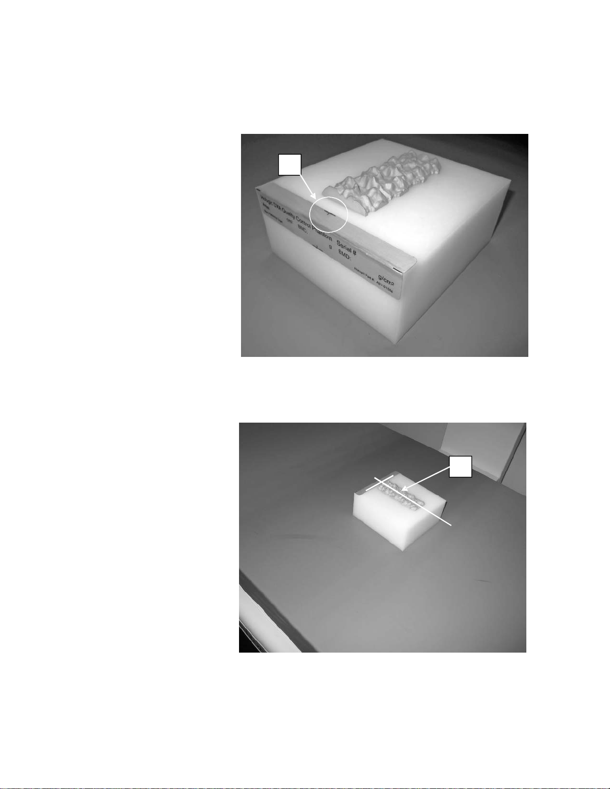
QDR Reference Manual
A
B
Position the Spine Phantom
T o position the spine phantom on the table refer to Figure 5-1 and
Figure 5-2 and follow the procedure below.
Figure 5-1
Spine Phantom Registration
Mark
Figure 5-2
Spine Phantom and Laser
Cross Hair Position
Quality Control 5-3
Page 94
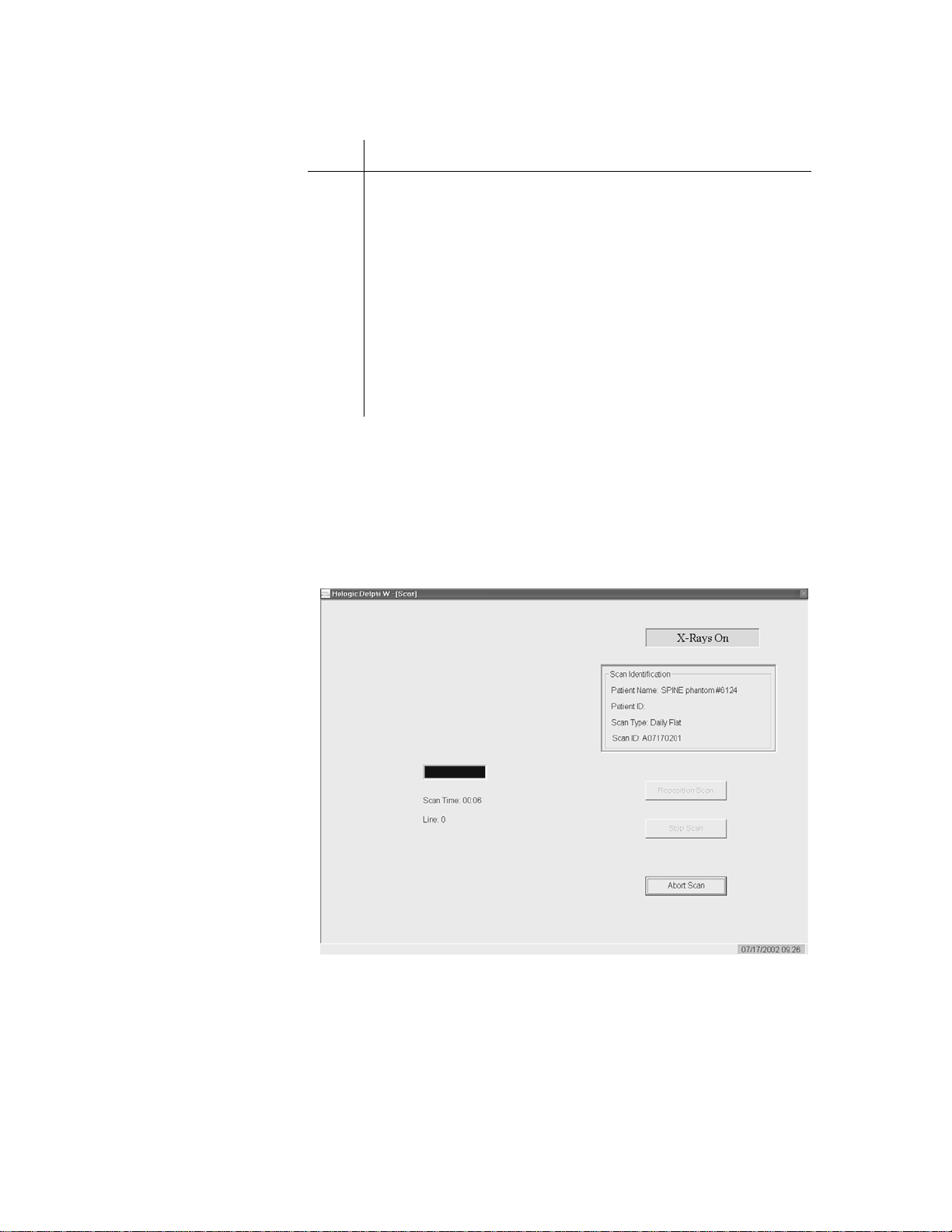
QDR Reference Manual
KP0886-0504
To position the spine phantom on the table:
Step Action
1 Place the spine phantom on the table with the registration
mark (see "A" in Figure 5-1) to the left, foot end.
Note: Use the horizontal line of
the laser to confirm that the
phantom is straight on the table
Automatic System Test
The QDR system automatically performs a system test to verify
proper operation of its X-ray subsystem prior to scanning the
spine phantom. The following screen is displayed during system
test:
2 Position the phantom parallel to the back of the table.
3 Align the laser cross hair (see "B" in Figure 5-2) with the
registration mark.
4 Once the spine phantom is properly positioned, click the
Continue button.
The systems starts performing an automatic system test.
5-4 Quality Control
Page 95
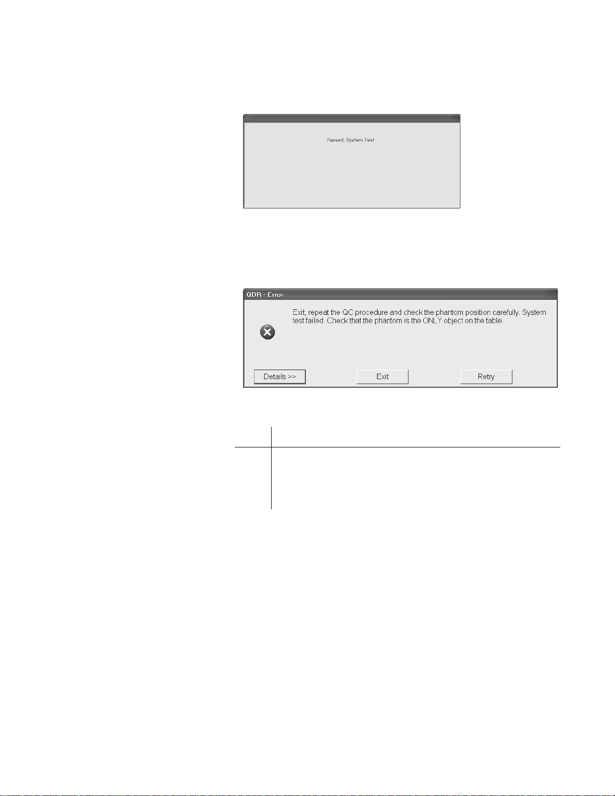
QDR Reference Manual
KP0886-0505
KP0886-0506
If the automatic system test succeeds, a message appears on the
screen indicating that the system test passed.
If the automatic system test fails, the system displays a message
stating that the test failed, and information on how to correct the
error.
Note: The error message varies
depending on why the system test
failed.
Auto QC Passed
To correct a failed system test:
Step Action
1 Read the message in the Error window.
2 Perform the steps as instructed in the Error window to
correct the error and repeat the QC procedure.
Upon successful completion of the system test, the system runs
Auto QC. When Auto QC has been completed, a window appears
giving either a passed or failed message.
When Auto QC passes, the message is “Daily QC has passed”
(see Figure 5-3).
Quality Control 5-5
Page 96

Figure 5-3
KP0886-0507
KP1035-0507a
QC Results Windo w fo r A uto QC
Passed
QDR Reference Manual
The QC Results window for a passed Auto QC contains 3
buttons: Review Analysis, Plot, and OK.
Note: If QC passes, performing
Review Analysis and/or Plot is
not required.
Review Analysis
Figure 5-4
Auto QC Analysis Window
If Auto QC passed, click on OK to start the daily operation of the
System.
The Review Analysis button and the Plot button are described
below (for informational purposes).
To review the analysis of the Auto QC scan, click on the Review
Analysis button from the QC Results window for a passed Auto
QC. The Analysis window appears (see Figure 5-4).
Verify that the phantom has been properly positioned and that the
scan was properly analyzed. If these items appear to be
satisfactory, click Close to continue.
If not, click Close and repeat the procedure, making sure to
properly position the phantom.
From the QC Results window (see Figure 5-3) click OK to start
the daily operation of the System.
5-6 Quality Control
Page 97

QC Plot
KP1035-0507b
QDR Reference Manual
To review the QC plot, click on the Plot button from the QC
Results window for a passed Auto QC. The QC Plot window
appears (see Figure 5-5).
Figure 5-5
QC Plot Window
About the QC Plot
When the QC Plot window is displayed, the BMD values are
shown along the y axis (left side) of the QC plot. The example
above shows the mean value at calibration time (green horizontal
center line) as 0.987.
The BMD tab is displayed by default. To show BMC or Area
values, select the appropriate tab by clicking on it.
The QC Plot Window contains four buttons
Button Function
<< Back Returns to the Auto QC passed window
(see Figure 5-3).
Plot Regression Refer to Plot Regression on page 5-20
Print Prints the QC Plot
Close Returns to the system main window
A QC plot is a graph of the results of a series of scans of the same
QC Spine Phantom over time. The graph shows a number of
statistical indexes designed to help you to determine if there have
been significant changes in the measurements generated from the
scans.
Scan Dates
Scan dates are displayed along the horizontal axis. The example
above shows the scan dates from August, 2000 to October, 2002.
Quality Control 5-7
Page 98

QDR Reference Manual
Data Points
The small green circles are called data points. One data point
displays for each analyzed QC scan that is included in the QC
plot. The most recent data point is shown as a filled in green
circle. Any data point that falls off the graph (above or below) is
displayed as a red cross at the top (for data point above the scale)
or bottom (for data point below the scale) of the graph.
Mean Value at Calibration
The green horizontal line indicates the mean value at calibration.
This value is set by Hologic and is located at the mean value of
the measured parameter (in this case BMD) when your system
was calibrated. It is used as a guideline to compare the results of
your Daily QC scans to your QDR system when it was last
calibrated.
QC Limit Values
Note: An obvious drift, or points
outside the limit lines, should be
reported to Hologic.
The red dashed lines represent the upper and lower QC limits for
your system. The limits are set by Hologic and are located at ±
(plus or minus) 1.5% of the mean value at calibration
Setup
The setup area shows the type of QC scan performed, phantom
type (Spine, Block or Hip) and ID, and system serial number.
Reference Values
The Reference Values area shows the values that were
determined during the most recent database setup. It includes the
limits, the mean BMD, and the standard deviation (SD) for the
mean.
Plot Statistic
The Plot Statistics area shows the following:
• Number of Points
Number of scans contained in the QC plot.
• Mean
The mean is the average of all QC scans plotted.
• S.D.
The S.D. is the Standard Deviation from the mean for the
QC scans in the plot. The standard deviation indicates the
spread of plotted values from the mean.
•CV
The CV is the coefficient of variation for the values in the
5-8 Quality Control
Page 99

Auto QC Failed
KP1035-0508
KP1035-0508a
Figure 5-6
QC Results Windo w fo r A uto QC
Failure
QDR Reference Manual
graph. The smaller the CV percentage, the better the
precision of the results.
If Auto QC fails, the message is “ Daily QC faile d” and a series of
steps is provided as shown in the example in Figure 5-6.
If Auto QC fails, the QC Results Window contains four buttons:
Details, Review Analysis, Plot and OK.
Details
Figure 5-7
QC Results Details Window
Note: If the phantom is
positioned correctly and QC
fails a second time, contact
Hologic Customer Service.
Review Analysis
Clicking Details provides additional information about the QC
failure as shown in the example in Figure 5-7.
Clicking the Review Analysis button displays an analysis
window similar to the one shown in the example in Figure 5-4.
From this window you will be able to verify that the phantom has
been properly positioned and that the scan was properly analyzed.
Click Close to return to the QC Results Window.
Quality Control 5-9
Page 100

QDR Reference Manual
KP0886-0512
Type: Spine, Block, or Hip
Phantom Number
<Type> Phantom # < Phantom ID>
Plot
Clicking Plot from the QC Results window for a failed Auto QC
displays the Analysis window of the QC Plot (similar to the one
in Figure 5-5).
OK
Clicking OK, from the QC Results window for a failed Auto QC,
returns to the system main window so Daily QC can be re-run.
About the QC Spine Phantom
Your QDR system includes a DXA spine phantom that is used
during the Daily QC procedure. It is used to test the system’s
calibration and precision. The phantom is designed to produce
scan data that resembles patient data. Other phantom types are
available from Hologic.
Each QC Spine Phantom is assigned a name in the patient name
field. The information about the QC Spine Phantom is stored in
the patient database. If a patient name for the QC Spine Phantom
does not exist, the daily QC procedure will create a record.
The format of the patient name for the QC Spine Phantom is as
follows:
5-10 Quality Control
 Loading...