

Page 1
RFID Board Instructions for FCC & IC Filing
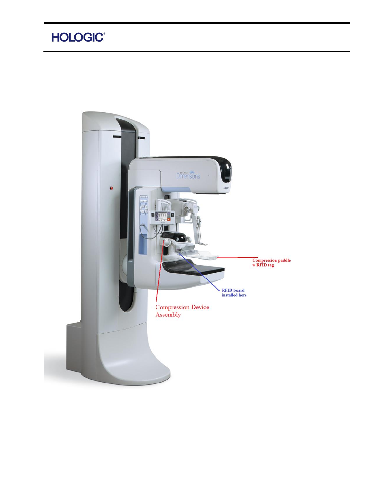
Hologic Inc. currently manufactures an RFID interface board that is used to detect the breast
compression paddle in Hologic mammography equipment. RFID board as a module is installed in
the COMPRESSION DEVICE assembly. Corresponding tag is located in the breast compression
paddle as seen below.
Form ENG-0013-T01, Rev. 002
Page 2
RFID Board Instructions for FCC & IC Filing
The circuit board contains a microcontroller to simulate I2C functionality, an I2C based A/D
converter, an integrated PCB printed antenna, and additional supporting circuitry. The board
interfaces with the rest of the system through a single 4-pin header consisting of power, ground
and I2C bus.
Compression Device Assembly is performed per assembly procedure AP-03659.
RFID board in addressed in step 2.16 through 2.18
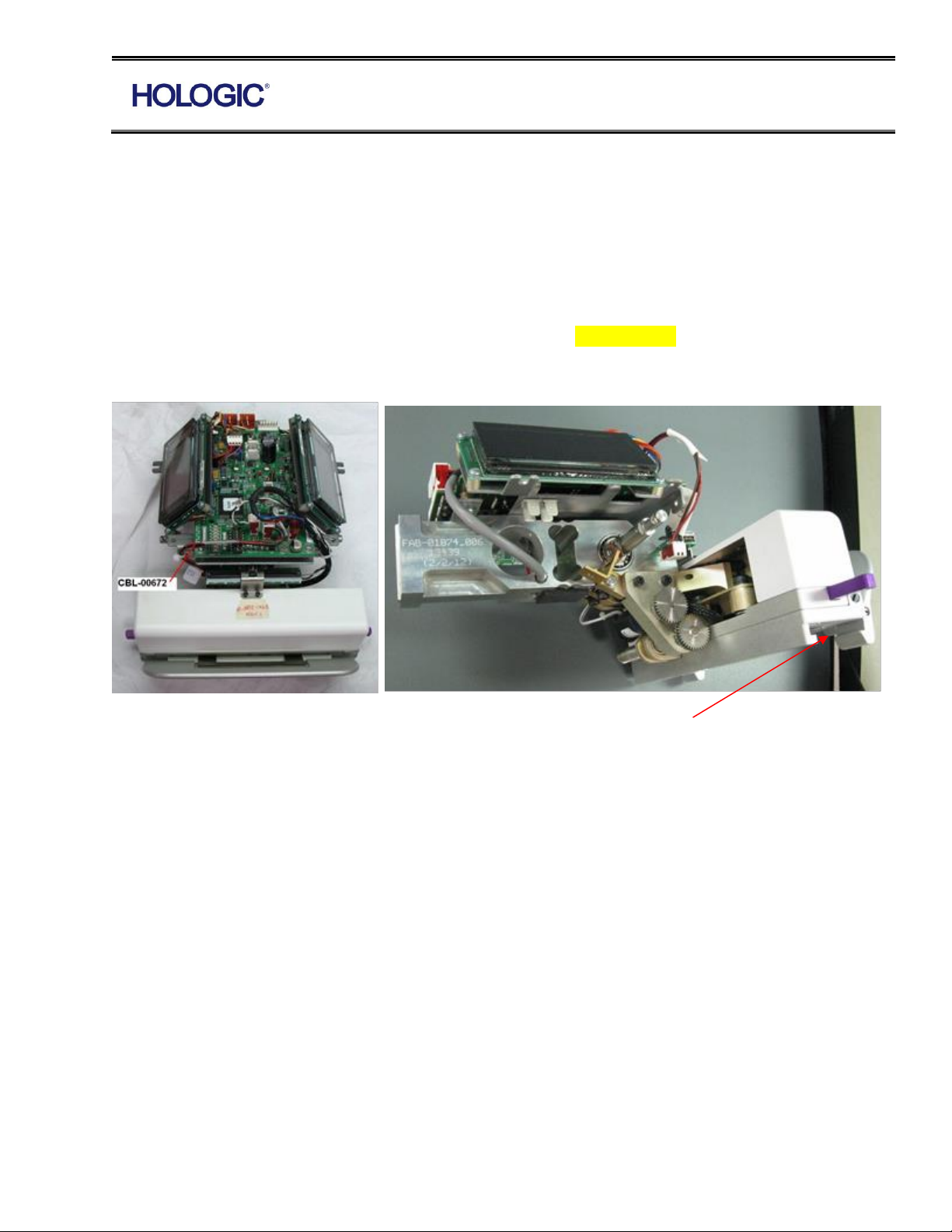
2.16 Attach completed VCD display to top of the load cell using (3) 6-32 x 5/8” Pan Head Phillips
SEMS (2-500-9772). Attach ‘DJ4’ of RFID Board assembly (PCB-01673) to the interface board
(PCB-00095). Shift the paddle assembly fully to the left, tie wrap (1-090-0179) the RFID cable to
the frame and return the paddle assembly to the center.
RFID Board Goes Here
2.17 Attach Shifting Breast Tray Harness (CBL-00672) to ‘EJ1’ of the paddle position sensor
board (PCB-00186) and ‘DJ9’ of the compression device interface board (PCB-00095). Tie wrap (1-
090-0179) to frame.
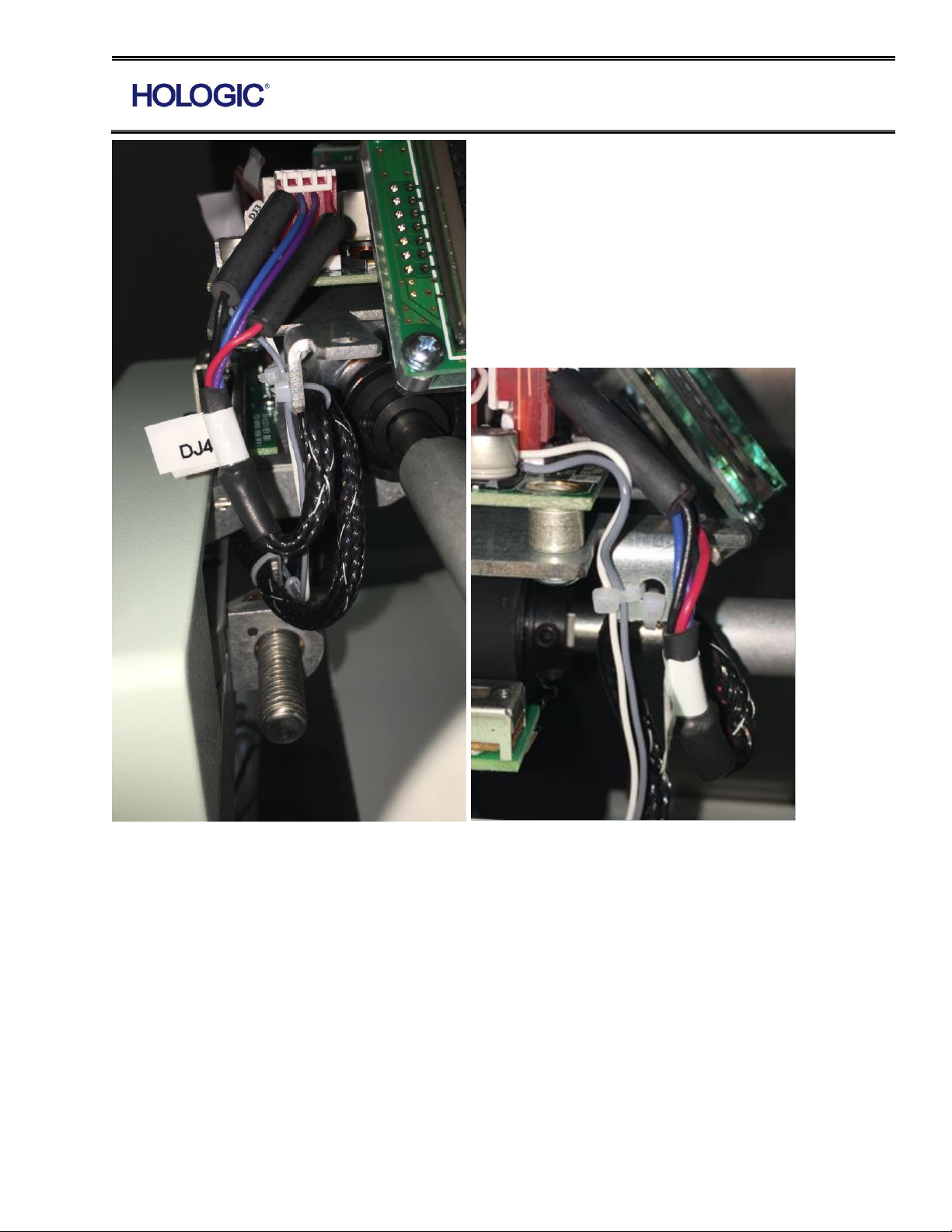
2.18 Attach the MOTOR ASSY/CONNECTOR (MEL-00225) to ASSY.,COMP. DEVICE
INTERFACE BD (PCB-00095). Connect “DJ1” load cell cable to ASSY.,COMP. DEVICE
INTERFACE BD (PCB-00095). See wire routing photos below for detail on how to properly dress
the wire to ensure the compression device helmet can be properly mounted later.
Form ENG-0013-T01, Rev. 002
Page 3
RFID Board Instructions for FCC & IC Filing
2.19 Test completed assembly per TP-00517.
Instruction for Final Product Labeling
Finish product will be labeled with the FCC and IC identifiers of the module.
Final product label shall say:
Contains FCC ID:YUJ-PCB01673
Contains IC:9281A-PCB01673
Form ENG-0013-T01, Rev. 002
Page 4

RFID Board Instructions for FCC & IC Filing
Note
End user does not have access to RFID board. No modifications are permitted by the end user.
Only Hologic trained field engineer are authorized to service the machine and perform necessary
replacement of the RFID board when service is ordered on a system.
FCC Compliance Statements
47 CFR §15.105(b)
This equipment has been tested and found to comply with the limits for a Class B digital device,
pursuant to part 15 of the FCC Rules. These limits are designed to provide reasonable protection
against harmful interference in a residential installation. This equipment generates, uses and can
radiate radio frequency energy and, if not installed and used in accordance with the instructions,
may cause harmful interference to radio communications. However, there is no guarantee that
interference will not occur in a particular installation. If this equipment does cause harmful
interference to radio or television reception, which can be determined by turning the equipment off
and on, the user is encouraged to try to correct the interference by one or more of the following
measures:
—Reorient or relocate the receiving antenna.
—Increase the separation between the equipment and receiver.
—Connect the equipment into an outlet on a circuit different from that to which the receiver is
connected.
—Consult the dealer or an experienced radio/TV technician for help.
47 CFR §15.19 Labeling requirements
This device complies with part 15 of the FCC Rules. Operation is subject to the following two
conditions: (1) This device may not cause harmful interference, and (2) this device must accept any
interference received, including interference that may cause undesired operation.
RF Exposure
This device complies with FCC RF radiation exposure limits set forth for general
population (uncontrolled exposure).
Form ENG-0013-T01, Rev. 002
Page 5

RFID Board Instructions for FCC & IC Filing
Industry Canada Statements
This device complies with Industry Canada licence-exempt RSS standard(s). Operation is subject
to the following two conditions: (1) this device may not cause interference, and (2) this device must
accept any interference, including interference that may cause undesired operation of the device.
Under Industry Canada regulations, this radio transmitter may only operate using an antenna of
a type and maximum (or lesser) gain approved for the transmitter by Industry Canada.
To reduce potential radio interference to other users, the antenna type and its gain should be so
chosen that the equivalent isotropically radiated power (e.i.r.p.) is not more than that necessary
for successful communication.
This device complies with Industry Canada RF radiation exposure limits set forth for general population
(uncontrolled exposure).
French
Le présent appareil est conforme aux CNR d’Industrie Canada applicables aux appareils radio
exempts de licence. L’exploitation est autorisée aux deux conditions suivantes: (1) il ne doit pas
produire de brouillage, et (2) l’utilisateur du dispositive doit être prêt a accepter tout brouillage
radioélectrique reçu, même si ce brouillage est susceptible de compromettre le fonctionnement du
dispositive.
Conformément à la réglementation d’Industrie Canada, le présent émetteur radio peut fonctionner
avec une antenne d’un type et d’un gain maximal (ou inférieur) approuvé pour l’émetteur par
Industrie Canada.
Dans le but de réduire les risques de brouillage radioélectrique à l’ intention d’autres utilisateurs,
il faut choisir le type d’antenne et son gain de sorte que la puissance isotrope rayonnée équivalente
(p.i.r.e.) ne dépasse pas l’intensité nécessaire à l’établissement d’une communication satisfaisante.
Le présent appareil est conforme aux niveaux limites d’exigences d’exposition RF aux personnes
définies par Industrie Canada.
Host Labeling
Per RSS-GEN § 4.3 The host product shall be properly labelled to identify the modules within the host
product.
Contains IC: 9281A-PCB01673
Form ENG-0013-T01, Rev. 002
 Loading...