

Page 1
NovaSure®
Instructions for Use and Controller
Operator’s Manual
Table of Contents
Physician Checklist ..................................1
System Description ..................................1
Indications .........................................3
Contraindications ...................................3
Warnings ..........................................3
Precautions ........................................4
Adverse Events .....................................5
Anticipated Post-Procedural Complications ..............6
Other Adverse Events ................................6
Clinical Study ....................................... 6
Patient Selection ..................................9
Patient Counseling ................................9
Pretreatment Preparation of Patient .....................9
NovaSure Impedance Controlled Endometrial Ablation System
Instructions for Use ................................. 10
Periodic Maintenance and Service:
Model 08-09 RF Controller ............................. 16
NovaSure Model 08-09 RF Controller LED Descriptions .....18
Troubleshooting Most Common Alarms:
Model 08-09 RF Controller ...........................18
Periodic Maintenance and Service:
Model 10 RF Controller .............................. 21
NovaSure Model 10 RF Controller Screen Icons .......... 21
Troubleshooting Most Common Alarms:
Model 10 RF Controller ............................... 22
Additional Troubleshooting ...........................24
Replacement Instructions ............................ 24
Specifications ..................................... 24
Cleaning and Sanitizing. . . . . . . . . . . . . . . . . . . . . . . . . . . . . . 28
Parts List .........................................28
Warranty .........................................28
Technical Support and Product Return Information. . . . . . . . 29
Symbol Definitions .................................30
ENGLISH
CAUTION: FEDERAL (USA) LAW RESTRICTS THIS DEVICE TO
SALE BY OR ON THE ORDER OF A PHYSICIAN TRAINED IN THE
USE OF THE DEVICE.
Read all instructions, cautions and warnings prior to use. Failure
to follow any instructions or to heed any warnings or precautions
could result in serious patient injury.
NOTE: The manual that accompanied the disposable device may
contain a more recent revision of the NovaSuresystem instructions
than the manual provided with the controller.
The NovaSuredisposable device is not to be used with other
controllers and/or RF generators, and the NovaSureRFcontroller is
not to be used with other disposable devices.
The NovaSure disposable device does not contain latex.
Physician Checklist
The physician must:
• have sufficient experience in performing procedures within the uterine
cavity, such as IUD insertion or dilation and curettage (D&C) and with
adequate training, knowledge and familiarity using the NovaSure
system;
• review and be familiar with the instructions and complete either
NovaSure training or be trained by a qualified physician;
• be aware of the appropriate sequence of actions detailed in the
Instructions for Use and Troubleshooting sections of this manual to
abort, resolve and/or continue the treatment in the event the system
detects a loss of CO2 during the cavity integrity assessment (CIA),
which indicates a possible uterine perforation.
Adjunct personnel must be familiar with these instructions and other
training materials prior to using the NovaSure system.
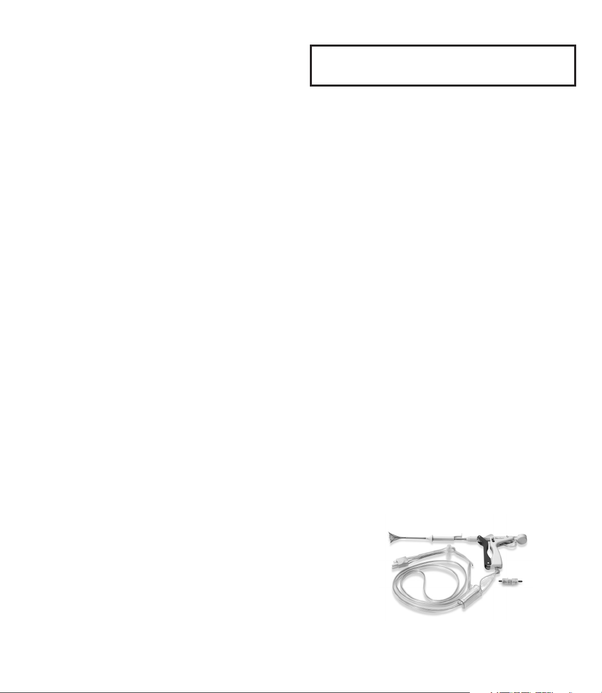
System Description
The NovaSure impedance controlled endometrial ablation system
consists of the NovaSure disposable device with connecting cord,
NovaSure RF controller (controller), NovaSure CO2 canister, desiccant,
foot switch and power cord, which are designed to be used together as
a system.
NovaSure Disposable Device with Connecting Cord,
1
Including Suction Line Desiccant
Page 2
ENGLISH
NovaSure Disposable Device Description
The NovaSure disposable device consists of a single-patient use,
conformable bipolar electrode array mounted on an expandable
frame that can create a confluent lesion on the entire interior
surface area of the uterine cavity. The disposable device is inserted
transcervically into the uterine cavity, and the sheath is retracted to
allow the bipolar electrode array to be deployed and conform to the
uterine cavity.
The bipolar electrode array is formed from a metalized, porous
fabric through which steam and moisture are continuously
suctioned from the desiccated tissue. The disposable device
works in conjunction with a dedicated NovaSure RF controller to
perform customized, global endometrial ablation in an average
of approximately 90seconds without the need for concomitant
hysteroscopic visualization or endometrial pretreatment. The
specific configuration of the bipolar electrode array and the
predetermined power of the controller create a controlled depth of
ablation in uteri sounding less than or equal to 10cm and having a
minimum cornu-to-cornu distance of 2.5cm.
During the ablation process, the flow of radio frequency (RF) energy
vaporizes and/or coagulates the endometrium regardless of its
thickness and desiccates and coagulates the underlying, superficial
myometrium.
The controller automatically calculates the optimal power level (W)
required for the treatment of the uterine cavity, based on uterine
size. As tissue destruction reaches an optimal depth, increasing
tissue impedance causes the controller to automatically terminate
power delivery, thereby providing a self-regulating process. Blood,
saline and other liquid present in the uterine cavity at the time
of the procedure, as well as vapor liberated from the desiccated
tissue, are evacuated by continuous, automatic suctioning.
The disposable device is connected to the controller via a cord
containing the RF cable, suction tubing used for pressure monitoring
during the cavity integrity assessment cycle and for suction during
the ablation cycle, and vacuum feedback tubing used for carbon
dioxide delivery during the cavity integrity assessment cycle and
vacuum monitoring during the ablation cycle. The disposable device
has been sterillized with ethylene oxide (EO).
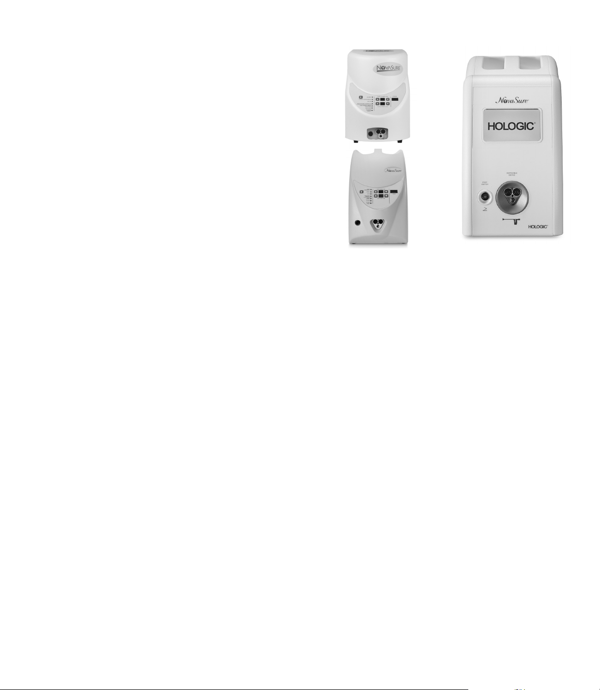
NovaSure Model 08-09
RF Controllers
NovaSure Model 10
RF Controller
NovaSure RF Controller Description
The NovaSure RF controller is a constant power output generator with a
nominal maximum power delivery capability of 180 watts. The controller
automatically calculates the power output based on the uterine cavity
length (sound measurement minus the length of the endocervical canal)
and width measurements that the user key-enters into the controller.
Monitoring tissue impedance during the ablation process automatically
controls the depth of endo-myometrial ablation. The NovaSure procedure
self-terminates once endometrial vaporization and superficial myometrial
desiccation have reached 50ohms of impedance at the tissue-electrode
interface, or when the treatment timer reaches two minutes. Integral
to the controller is the cavity integrity assessment system (CIA) which
is designed to determine whether there is a defect or perforation in the
wall of the uterus. After the disposable device is placed into the uterine
cavity, CO2 is delivered through the central lumen of the disposable
device into the cavity, via the vacuum feedback tubing, at a safe flow
rate and pressure. If the CO2 pressure in the cavity is maintained for a
short period of time, indicating that the uterine cavity is intact, then the
CIA will allow the NovaSure RF controller to be enabled and proceed with
the treatment phase. A vacuum pump contained within the NovaSure
RF controller creates and maintains a vacuum in the uterine cavity
throughout the endometrial ablation procedure. Once the vacuum is
stabilized, the vacuum level is monitored throughout the remainder of
the ablation process.
2
Page 3
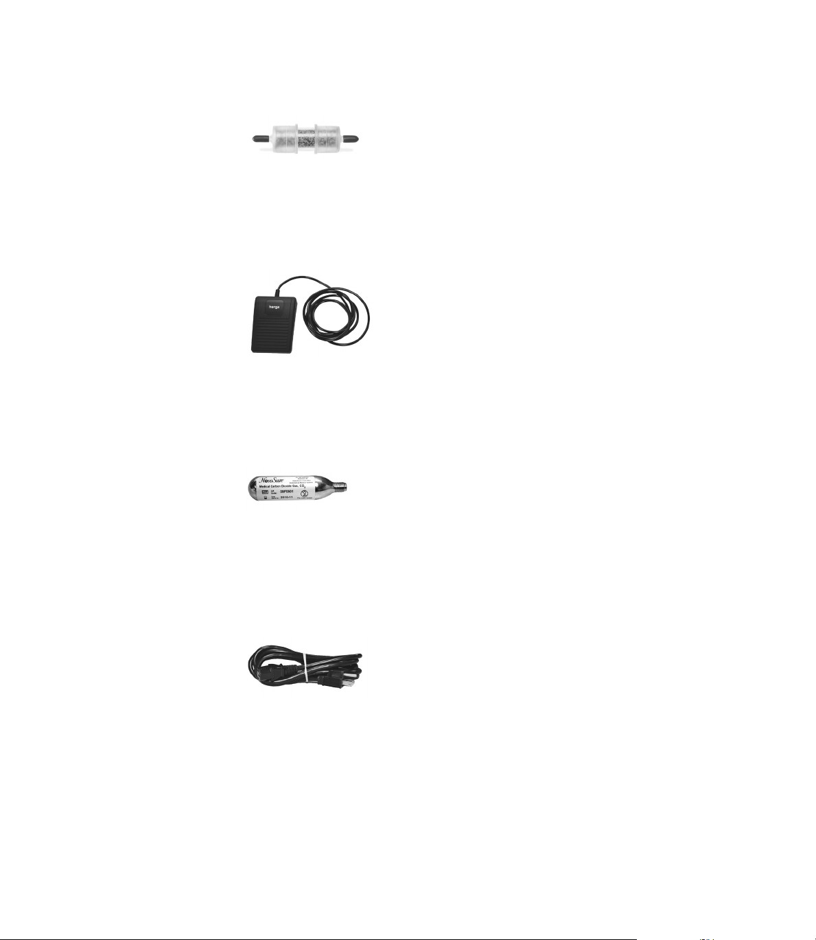
NovaSure Suction Line Desiccant
Description
The NovaSure suction line desiccant
is a non-sterile, single-patient use
component that the user attaches
in-line with the suction tubing, prior
to connecting the disposable device
to the NovaSure RF controller. The
desiccant absorbs the moisture
removed from the uterine cavity via
the suction tubing during the ablation
procedure.
NovaSure Foot Switch
Description
The NovaSure foot switch is a
pneumatic switch that connects to the
NovaSureRFcontroller front panel. It
is used to activate the NovaSure RF
controller and does not contain any
electrical components.
NovaSure CO2 Canister
Description
The NovaSure CO2 canister is a 16gram CO2 (USP) canister. It is attached
to the regulator located on the back
panel of the NovaSureRFcontroller
prior to applying line voltage to
the NovaSureRFcontroller. The
CO2 is used by the cavity integrity
assessment system to pressurize the
uterine cavity.
NovaSure AC Power Cord
Description
The NovaSure AC power cord,
a medical grade cord, connects
the NovaSure RF controller to
the appropriate line voltage. The
receptacle for the power cord, the
power input module, is located on
the back panel of the NovaSure RF
controller.
INDICATIONS
The NovaSure system is intended to ablate the endometrial lining of the
uterus in pre-menopausal women with menorrhagia (excessive bleeding)
due to benign causes for whom childbearing is complete.
CONTRAINDICATIONS
The NovaSure impedance controlled endometrial ablation system is
contraindicated for use in:
ENGLISH
• a patient who is pregnant or who wants to become pregnant in the
future. Pregnancies following ablation can be dangerous for both
mother and fetus.
• a patient with known or suspected endometrial carcinoma (uterine
cancer) or pre-malignant conditions of the endometrium, such as
unresolved adenomatous hyperplasia.
• a patient with any anatomic condition (e.g., history of previous
classical cesarean section or transmural myomectomy) or pathologic
condition (e.g., long-term medical therapy) that could lead to
weakening of the myometrium.
• a patient with active genital or urinary tract infection at the time of
the procedure (e.g., cervicitis, vaginitis, endometritis, salpingitis or
cystitis).
• a patient with an intrauterine device (IUD) currently in place.
Presence of an IUD in the uterine cavity can interfere with a NovaSure
procedure.
• a patient with a uterine cavity length less than 4cm. The minimum
length of the electrode array is 4cm. Treatment of a uterine cavity with
a length less than 4cm will result in thermal injury to the endocervical
canal.
• a patient with a uterine cavity width less than 2.5cm, as determined
by the WIDTH dial of the disposable device following device
deployment.
• a patient with active pelvic inflammatory disease.
WARNINGS
FAILURE TO FOLLOW ANY INSTRUCTIONS OR FAILURE TO HEED
ANY WARNINGS OR CAUTIONS COULD RESULT IN SERIOUS PATIENT
INJURY.
THE NOVASURE DISPOSABLE DEVICE MUST BE USED ONLY IN
CONJUNCTION WITH THE NOVASURE RF CONTROLLER.
THE NOVASURE PROCEDURE IS INTENDED TO BE PERFORMED ONLY
ONCE DURING A SINGLE OPERATIVE VISIT. THERMAL INJURY TO THE
BOWEL MAY OCCUR WHEN MULTIPLE NOVASURE THERAPY CYCLES
ARE PERFORMED DURING THE SAME OPERATIVE VISIT.
Uterine Perforation
• Use caution not to perforate the uterine wall when sounding, dilating
or inserting the disposable device.
• If the disposable device is difficult to insert into the cervical canal,
use clinical judgment to determine whether or not further dilation is
required.
• The NovaSure system performs a cavity integrity assessment (CIA)
to evaluate the integrity of the uterine cavity and sounds an alarm
warning of a possible perforation prior to treatment (Step 2.36).
(Although designed to detect a perforation of the uterine wall, it is
an indicator only and it might not detect all perforations under all
possible circumstances. Clinical judgment must always be used.)
• If a uterine perforation is suspected, the procedure should be
terminated immediately.
3
Page 4

ENGLISH
• If the cavity integrity assessment fails after reasonable attempts
to implement the troubleshooting procedures (step 2.36), abort
the procedure.
• For patients in whom the procedure was aborted due to a suspected
uterine wall perforation, a work-up for perforation should be
considered prior to discharge.
General
• Endometrial ablation using the NovaSure system is not a sterilization
procedure. Therefore, the patient should be advised of appropriate
birth control methods.
• Endometrial ablation does not eliminate the potential for endometrial
hyperplasia or adenocarcinoma of the endometrium and may mask the
physician’s ability to detect or make a diagnosis of such pathology.
• Endometrial ablation is intended for use only in women who do
not desire to bear children because the likelihood of pregnancy is
significantly decreased following the procedure. Pregnancy following
ablation may be dangerous for both mother and fetus.
• Patients who undergo endometrial ablation procedures who have
previously undergone tubal ligation are at increased risk of developing
post ablation tubal sterilization syndrome which can require
hysterectomy. This can occur as late as 10years post procedure.
• A health hazard may exist in the case where the NovaSure procedures
is performed in the presence of a thermally and electrically conductive
metal micro-insert that is improperly positioned (e.g., perforating the
fallopian tube or the myometrium). If this occurs, heat can be drawn
away from the intended treatment area toward other tissue and/or
organs in contact with the conductive object, which may be sufficient
to cause localized burns. As a result, correct placement of the metal
micro-insert must be confirmed prior to performing the NovaSure
procedure.
Technical
• Do not use the sterile, single-patient use disposable device if the
packaging appears to be damaged or there is evidence of tampering.
• The disposable device is for single-patient use only. Do not reuse or
re-sterilize the disposable device. The risk of reusing the disposable
device includes but is not limited to the following:
• ineffective procedure
• infection (major)
• electric shock
• transmission of communicable disease
• cervical laceration
• uterine perforation
• If any hysteroscopy procedure is performed with hypotonic solution
immediately prior to NovaSure treatment, then the uterine cavity must
be flushed with normal saline prior to treatment with the NovaSure
system. The presence of hypotonic fluid may reduce the efficiency of
the NovaSure system.
• Plugging the disposable device into the controller starts CO2 flow to
purge any air out of the disposable device and tubing. This purging
operation takes approximately 10seconds and must be performed
with the disposable device external to the patient to eliminate
the risk of air or gas embolism. The NovaSure RF controller CAVITY
ASSESSMENT LED flashes red (Model 08-09 RFCs) or a purging device
screen appears (Model 10 RFC) and an audible pulsed tone sounds
throughout the purge procedure. When the tone and the LED/screen
message stops it is safe to insert the disposable device.
• For patients with cardiac pacemakers or other active implants, a
possible hazard exists due to interference with the action of the
pacemaker that may occur and may damage the pacemaker. Consult
the pacemaker manufacturer for further information when use of the
NovaSure system is planned in patients with cardiac pacemakers.
• Care should be taken to ensure the patient does not contact metal
parts which are earthed or which have an appreciable capacitance to
earth.
• Danger: explosion hazard. Do not use in the presence of a flammable
anesthetic mixture. Do not use in the presence of flammable gases or
liquids.
• Failure of the NovaSureRFcontroller could result in an unintended
increase in output power.
PRECAUTIONS
• It has been reported in the literature that patients with a severely
anteverted, retroflexed or laterally displaced uterus are at greater risk
of uterine wall perforation during any intrauterine manipulation.
• A false passage can occur during any procedure in which the uterus
is instrumented, especially in cases of severe anteverted retroflexed
or a laterally displaced uterus. Use caution to ensure that the device is
properly positioned in the uterine cavity.
• The NovaSure system consists of the following components:
- single-patient use NovaSure disposable device with connecting cord
- NovaSure RF controller
- NovaSure CO2 canister
- NovaSure desiccant
- NovaSure foot switch
- power cord
To ensure proper operation, never use other components with the
NovaSure system. Inspect the components regularly for damage,
and do not use them if damage is apparent. The use of any cables or
accessories other than those specified in these instructions may result
in increased emissions or decreased immunity of the RF controller.
• The RF controller must be installed and put into service according
to the guidance provided in these instructions to ensure its
electromagnetic compatibility. Refer to the electromagnetic emissions
and immunity tables in the Specifications section.
• The RF controller should not be used adjacent to or stacked with other
equipment. If adjacent or stacked use is necessary, the RF controller
should be observed to verify normal operation in the configuration in
which it will be used.
4
Page 5

• Portable and mobile RF communications equipment can affect the
RF controller. Refer to the electromagnetic immunity tables in the
Specifications section for recommended separation distances.
• Patients who have undergone endometrial ablation and are later
placed on hormone replacement therapy should have a progestin
included in their medication regimen in order to avoid the increased
risk of endometrial adenocarcinoma associated with unopposed
estrogen replacement therapy.
• The safety and effectiveness of the NovaSure system has not been
fully evaluated in patients:
- with a uterine sound measurement greater than 10cm;
- with submucosal fibroids that distort the uterine cavity;
- with bicornuate, septate or sub-septateuteri;
- with medical (e.g., GnRH agonist) or surgical pretreatment;
- who have undergone a previous endometrial ablation including the
NovaSure endometrial ablation procedure; or,
- who are post-menopausal.
• Do not attempt to repair the controller if problems are suspected.
Call Hologic Technical Support or a Hologic sales representative for
instructions.
• Cables to the disposable device should be positioned such that contact
with patient or other leads is avoided.
• The user should inspect the disposable device for damage prior to use.
• The suction line desiccant is non-sterile, and the packaging should not
be placed in the sterile field.
• If the ARRAY POSITION LED light is illuminated on Models 08-
09, or an Array Position message is displayed on the Model 10
screen, see the Troubleshooting section under “ARRAY POSITION
ALARM”
• Do not use the NovaSure suction line desiccant if desiccant material is
pink in color.
• The disposable device must be external to (outside of) the patient
before connecting the cord to the appropriate port on the front panel of
the controller (step 2.15).
• The carbon dioxide canister contains gas under high pressure. In the
event of a breached CO2 canister or line, allow the canister to exhaust
completely, and allow the canister and/or lines to equilibrate to room
temperature prior to handling.
• CO2 continuously flows from the time that the disposable device is
plugged into the controller until the CIA portion of the procedure is
complete. To minimize the duration of CO2 flow and potential risk of
embolism, perform the seating procedure immediately after inserting
the disposable device and proceed directly from the seating procedure
to the CIA.
• Electrically conductive objects (e.g., monitoring electrodes from other
devices) that are in direct contact with the electrode array of the
disposable device or in close proximity to the electrode array may
draw current away from the array. This may result in localized burns
to the patient or physician or in distortion of the electrical field of the
array, which would change the therapeutic effect (under-treatment or
ENGLISH
over-treatment). It may also result in distortion of the current in the
conductive object, e.g., monitors may display false readings.
• Grounding reliability is only achieved when equipment is connected to
a receptacle marked “hospital grade”.
• To avoid risk to patient and operators, do not use this equipment in
the presence of intentional magnetic sources, intentional ultrasound
sources, or intentional heat sources.
• The cervical collar must be fully retracted to its proximal position in
order to minimize the potential for damage to the sheath when closing
the array.
• The plastic tubing in the NovaSure Disposable Device contains di-(2ethylhexyl) phthalate; DEHP. In accordance with European Commission
Directive 67/548/EEC, it is noted here that DEHP may impair fertility;
it also may cause harm to the unborn child. The NovaSure device is
contraindicated for use in pregnant women or women that want to
become pregnant in the future. Pregnancies following ablation can be
dangerous for both mother and fetus. Sound medical judgment should
be used.
NovaSure 3-Year Clinical Data
Adverse Events
The NovaSure system was evaluated in a randomized, prospective,
multi-center clinical study of 265patients with abnormal uterine
bleeding comparing the NovaSure system to a control arm of wire loop
resection of the endometrium followed by rollerball ablation.
Table 1A. Intra-Operative Adverse Events
NovaSure
Adverse Event
Bradycardia
Uterine perforation
Cervical tear
Cervical stenosis
TOTAL
Table 1B. Post-Operative Adverse Events < 24 Hours
Adverse Event
Pelvic pain/cramping 6 (3.4%) 4 (4.4%)
Nausea and/or vomiting 3 (1.7%) 1 (1.1%)
TOTAL 9 (5.1%)* 5 (5.6%)**
* Nine events reported in 6 (3.4%) patients
** Five events reported in 4 (4.4%) patients
n=175 (%)
1 (0.6%) 0 (0.0%)
0 (0.0% 3 (3.3%)
0 (0.0% 2 (2.2%)
0 (0.0% 1 (1.1%)
1 (0.6%) 6 (6.7%)
NovaSure
n=175 (%)
Loop Resection
Plus Rollerball
n=90 (%)
Loop Resection
Plus Rollerball
n=90 (%)
5
Page 6

ENGLISH
Table 1C. Post-Operative Adverse Events > 24 Hours – 2 Weeks
NovaSure
Adverse Event
Hematometra 1 (0.6%) 0 (0.0%
Urinary tract infection 1 (0.6%) 1 (1.1%)
Vaginal infection 1 (0.6%) 0 (0.0%
Endometritis 0 (0.0% 2 (2.2%)
Pelvic inflammatory disease 0 (0.0% 1 (1.1%)
Hemorrhage 0 (0.0% 1 (1.1%)
Pelvic pain/cramping 1 (0.6%) 1 (1.1%)
Nausea and/or vomiting 1 (0.6%) 1 (1.1%)
TOTAL 5 (2.9%)* 7 (7.8%)**
* Five events reported in 4 (2.3%) patients
** Seven events reported in 6 (6.7%) patients
Table 1D. Post-Operative Adverse Events > 2 Weeks – 1 Year
Adverse Event
Hysterectomy 3 (1.7%) 2 (2.2%)
Hematometra 1 (0.6%) 2 (2.2%)
Urinary tract infection 2 (1.1%) 2 (2.2%)
Vaginal infection 5 (2.9%) 2 (2.2%)
Endometritis 2 (1.1%) 1 (1.1%)
Pelvic inflammatory disease 2 (1.1%) 0 (0.0%
Hemorrhage 1 (0.6%) 0 (0.0%
Pelvic pain/cramping 5 (2.9%) 6 (6.7%)
TOTAL 21 (12.0%)* 15 (16.17%)**
* 21 events in 19 (10.9%) patients
** 15 events in 15 (16.7%) patients
n=175 (%)
NovaSure
n=175(%)
Loop Resection
Plus Rollerball
n=90 (%)
Loop Resection
Plus Rollerball
n=90 (%)
Anticipated Post-Procedural Complications
For any endometrial ablation procedure, commonly reported postoperative events include the following:
• Cramping/pelvic pain was reported for 3.4% of the NovaSure patients
and 4.4% of the wire resection loop plus rollerball-treated patients
within 24hours of the procedure. Postoperative cramping can range
from mild to severe. This cramping will typically last a few hours and
rarely continues beyond the first day following the procedure.
• Nausea and vomiting were reported for 1.7% of the NovaSure patients
and 1.1% of the wire loop resection plus rollerball patients within
24hours of the procedure. When present, nausea and vomiting
typically occur immediately following the procedure, are associated
with anesthesia and can be managed with medication.
• Vaginal discharge
• Vaginal bleeding/spotting
Other Adverse Events
As with all endometrial ablation procedures, serious injury or death can occur.
The following adverse events could occur or have been reported in
association with the use of the NovaSure system:
• post-ablation tubal sterilization syndrome
• pregnancy-related complications (NOTE: PREGNANCY FOLLOWING
ENDOMETRIAL ABLATION IS VERY DANGEROUS FOR BOTH THE
MOTHER AND THE FETUS.)
• thermal injury to adjacent tissue
• perforation of the uterine wall
• difficulty with defecation or micturition
• uterine necrosis
• air or gas embolism
• infection or sepsis
• complications leading to serious injury or death
Clinical Study
Purpose: Safety and effectiveness of the use of the NovaSure system
was compared to wire loop resection of the endometrium followed by
rollerball ablation in premenopausal women suffering from menorrhagia
secondary to benign causes.
Pretreatment: Patients randomized into the NovaSure arm received
no endometrial pretreatment (e.g., hormone, D&C or patient timing).
Patients randomized into the control arm received wire loop resection as
an endometrial pretreatment.
Study endpoints: The primary effectiveness measure was a validated
menstrual diary scoring system developed by Higham (Higham JM,
O’Brien PMS, Shaw RW Br J Obstet Gynaecol 1990; 97:734-9).
Assessment of menstrual blood loss was performed using a pictorial
blood loss assessment chart (PBLAC). Patient success was defined as
a reduction in menstrual flow at 1 year post-procedure to a diary score
of <75. Study success was defined as a statistical difference of less
than 20% in patient success rates between the NovaSure impedance
controlled endometrial ablation system and wire loop resection plus
rollerball ablation. Patients were contacted at two and three years and
asked a series of questions regarding their bleeding over the previous
12months. Each patient’s menstrual bleeding status was determined
at two and three years using the one-year PBLAC score and bleeding
pattern as a reference. Thus, it was possible to directly compare a
patient’s bleeding pattern or menstrual status at one year to the bleeding
pattern at two and three years.
Secondary endpoints included anesthesia regimen, length of procedure
and responses from a quality-of-life questionnaire. Safety evaluation was
based on the adverse events reported during the study.
Methods: A randomized (2:1), prospective clinical study was conducted
at 9clinical sites and included 265patients diagnosed with menorrhagia.
Menstrual diary scores were collected pre-operatively and monthly for
12months post-procedure. Patients were treated at any time in their
menstrual cycle. None of the patients received hormonal pretreatment
to thin the endometrial lining. Control patients received hysteroscopic
6
Page 7

wire loop resection of the endometrium as a mechanical means of
endometrial pretreatment followed by rollerball ablation. Study subjects
were required to meet the following key patient selection criteria:
Inclusion criteria
• Refractory menorrhagia with no definable organic cause (dysfunctional
uterine bleeding)
• Ages 25 to 50years of age
• Uterine sound measurement of 6.0–10.0cm (external os to internal
fundus)
• Minimum PBLAC score of >150 for 3months prior to study enrollment;
or PBLAC score >150 for one month for women who:
- had at least 3 prior months (documented) failed medical therapy;
- had a contraindication to medical therapy; or
- refused medical therapy.
Exclusion criteria
• Presence of bacteremia, sepsis or other active systemic infection
• Active or recurrent chronic pelvic inflammatory disease
• Patient with documented coagulopathies or on anticoagulants
• Symptomatic endometriosis
• Prior uterine surgery (except low segment cesarean section)
that interrupts the integrity of the uterine wall e.g., transmural
myomectomy or classical cesarean section
• Prior endometrial ablation
• Patient on medications that could thin the myometrial muscle, such as
long-term steroid use
• Patient desire to have children or to preserve fertility
• Patient currently on hormonal birth control therapy or unwilling to use
a non-hormonal birth control post-ablation
• Abnormal/obstructed cavity as confirmed by hysteroscopy, SIS or HSG.
Specifically:
- septate or bicornuate uterus or other congenital malformation of the
uterine cavity
- pedunculated, submucous leiomyomata or other leiomyomata which
distort the cavity; polyps (larger than 2cm) which are likely to be the
cause of the patient’s menorrhagia
- presence of an IUD
• Suspected or confirmed uterine malignancy within the last five years
as confirmed by histology
• Endometrial hyperplasia as confirmed by histology
• Unaddressed cervical dysplasia
• Elevated FSH levels consistent with ovarian failure >40IU/ml
• Pregnancy
• Active sexually transmitted disease
Patient population: A total of 265patients were enrolled in this study.
Patients were between the ages of 25 to 50 with 46% under the age
of 40 and 54% 40years of age or older. There were no differences in
demographic or gynecological history parameters between the treatment
groups, between the age groupings or among the nine investigational sites.
ENGLISH
Table 2. Patient Accountability
Number of Patients NovaSure Wire Loop
Resection
Plus Rollerball
Entered into Study
(Intent-to-Treat population)
Aborted procedures*
Treated 171 88
Additional treatment* -4 -2
Hysterectomy*
Lost to follow-up* -5 -2
Hodgkin’s disease* -1 0
Pelvic Pain - administered
leuprolide*
12-Month
follow-up data available
Additional treatment* -2 -1
Hysterectomy*
Lost to follow-up* -2 -5
Missed visit -1 -1
Declined to participate* -1 0
Pregnancy* -1 0
24-Month
follow-up data available
Additional treatment* 0 -4
Hysterectomy*
Lost to follow-up* -4 -2
36-Month follow-up 138 67
Subject lost to follow-up at
24 mos., returned at 36 mos.
36-Month follow-up data
available
* Discontinued patients
1
Four NovaSure did not meet protocol Inclusion Criteria; Two Rollerball had uterine perforation
2
For hysterectomy, see Table 7
1
2
2
2
175 90
-4 -2
-3 -2
-1 0
157 82
-3 -1
147 74
-5 -1
+1 +1
139 68
Results
Primary effectiveness endpoint: bleeding score
Patient success at 12-months post-procedure is defined as a reduction
in diary score from >150 pre-operatively to <75 post-procedure.
Amenorrhea is defined as a score of 0. Success at 24 and 36 months,
based on telephone questionnaires, is defined as elimination of bleeding
or reduction to light or normal flow. Data presented in Table 3 (below)
represent the clinical results based on the total number of 265 patients
randomized (Intent-to-Treat group (ITT)) for the study. The worst-case
scenario is presented whereby each of the discontinued patients
7
Page 8

ENGLISH
(described in Table 2 for patient accountability) is counted as a “failure”
for calculating the values listed in the table.
Table 3. Effectiveness: Success Rates–Intent-To-Treat Patients
Wire Loop Resection
NovaSure
(n=175)
Plus Rollerball
(n=90)
Months post ablation 12* 24** 36** 12* 24** 36**
Number of
successful patients 136 143 134 67 68 63
Study success rate 77.7% 81.7% 76.6% 74.4% 75.6% 70.0%
# of patients with
Amenorrhea 63 64 58 29 26 23
Amenorrhea rate 36.0% 36.6% 33.1% 32.2% 28.9% 25.6%
* Based on diary scores
** Based on telephone questionnaires
Secondary effectiveness endpoint: quality of life
Patient quality of life (QOL) was assessed by administering the quality of
life questionnaire (SF-12) and the menstrual impact questionnaire prior
to treatment and at 3, 6, 12, 24 and 36months post-procedure. Table4
shows the patient responses for both groups pre-operatively, where
appropriate, and at 12, 24 and 36months post-procedure.
Table 4. Effectiveness: Quality of Life (QOL)
Wire Loop Resection
NovaSure
Number of Patients Responding to Quality of Life Questionaire
Pre-operatively 175 90
12 Months 154 82
24 Months 143 73
36 Months 139 67
Percent of Patients Satisified Or Very Satisified
12 Months 92.8% 93.9%
24 Months 93.9% 89.1%
36 Months 96.3% 89.7%
Percent of Patients Who Probably Or Definitely Would Recommend
This Procedure
12 Months 96.7% 95.9%
24 Months 96.6% 94.5%
36 Months 97.8% 92.6%
Percent of Patients with Dysemenorrhea
Pre-operatively 57.1% 55.6%
12 Months 20.8%
&
24 Months 20.3%* 30.1%*
36 Months 17.3%* 28.4%*
Percent of Patients with PMS
Pre-operatively 65.1% 66.7%
12 Months 36.4%* 35.4%*
24 Months 44.0%* 46.6%*
36 Months 34.5%* 41.2%*
Plus Rollerball
34.2%
#
*,&
Table 4. Effectiveness: Quality of Life (QOL)
Wire Loop Resection
NovaSure
Plus Rollerball
Percent of Patients Reporting Sometimes, Frequently Or Always
Have Difficulty Performing Work Or Other Activities Due to Menses
Pre-operatively 66.3% 65.5%
12 Months 9.9%* 8.6%*
24 Months 14.5%* 15.0%*
36 Months 16.3%* 13.3%*
Percent of Patients Reporting Sometimes, Frequently Or Always
Feel Anxious Due to Menses
Pre-operatively 74.7% 68.9%
12 Months 23.6%* 18.5%*
24 Months 24.2%* 19.2%*
36 Months 18.7%* 19.1%*
Percent of Patients Reporting Sometimes, Frequently Or Always
Miss Social Activities Due to Menses
Pre-operatively 63.3% 62.2%
12 Months 8.5%* 8.6%*
24 Months 9.0%* 11.1%*
36 Months 8.1%* 10.8%*
# Not all patients completed questionnaire
* Statistically significant difference from pre-operative response (Chi-Square; p<0.05)
& Statistically significant difference between NovaSure and Rollerball Groups
(Chi-Square; p=0.02)
Safety endpoint
Adverse event information is described in the “Adverse Events” section of this manual.
Secondary endpoint: procedure time
Procedure time, a secondary endpoint, was determined for each patient
by recording the time of device insertion and the time of device removal.
The mean procedure time for the NovaSure patients was significantly
less than the procedure time for the rollerball group, (4.2 ±3.5 minutes
and 24.2 ±11.4 minutes, respectively). Mean time for application of RF
energy was 84.0 ±25.0 seconds in a subset of monitored NovaSure
patients (Table5).
Table 5. Operative Procedure Time
Wire Loop Resection
NovaSure
Operative Parameters
n=175
Number of treated patients* 171 88
Procedure time minutes (± SD)
4.2 ± 3.5** 24.2 ± 11.4**
(Device insertion to device
removal)
Procedure time in seconds (±SD)
84.0 ± 25.0 ND
(Time of energy delivery)
* See Table 2 for patient accountability
** Statistically significant difference between treatment groups (Student’s t-test; p < 0.05)
#
Not determined
Plus Rollerball
n=90
#
8
Page 9

Secondary endpoint: anesthesia regimen
Anesthesia was left to the discretion of each patient, clinical investigator
and attending anesthesiologist. For the NovaSure patients, 27.0%
(47/174) had the procedure performed under general anesthesia or
epidural and 73.0% (127/174) under local and/or IV sedation. One
patient did not have a reported anesthesia regimen in this group. In
the rollerball group, 82.2% (74/90) of the patients were treated under
general anesthesia or epidural and 17.8% (16/90) under local and/or IV
sedation (Table6).
Table 6. Anesthesia Regimen
Wire Loop Resection
NovaSure
n=175*
General or epidural 27.0% 82.2%
Local and/or IV sedation 73.0% 17.8%
* One patient did not have a reported anesthesia regimen.
Plus Rollerball
n=90
Clinical observations
Hysterectomy
Fifteen women had a hysterectomy within the three years following the
ablation procedure. Table7 lists the reasons for hysterectomy.
Table 7. Hysterectomy
Wire Loop Resection
NovaSure
Reason For Hysterectomy
Adenocarcinoma diagnosed at
time of ablation procedure
Fibroids 2 0
Pelvic abscess 1 1
Endometriosis 3 0
Adenomyosis 4 0
Hematometra 0 1
Menorrhagia 0 1
TOTAL 11 (6.3%) 4 (4.4%)
7Hysterectomies were in patients <40years (7 NovaSure) and 8hysterectomies were in patients >40years
(4NovaSure; 4 Rollerball).
n=175
1 1
Plus Rollerball
n=90
Patient Selection
Menorrhagia can be caused by a variety of underlying problems,
including, but not limited to; endometrial cancer, myomas, polyps, drugs
and dysfunctional uterine bleeding (anovulatory bleeding). Patients
always should be screened and evaluated to determine the cause of
excessive uterine bleeding before any treatment option is initiated.
Consult medical literature relative to various endometrial ablation
techniques, indications, contraindications, complications and hazards
prior to the performance of any endometrial ablation procedure.
ENGLISH
Patient Counseling
As with any procedure, the physician needs to discuss risks, benefits
and alternatives with the patient prior to performing endometrial
ablation. Patient’s expectations should be set in a way that the patient
understands that the aim of the treatment is the reduction in bleeding to
normal levels.
The disposable device is intended for use only in women who do
not desire to bear children because the likelihood of pregnancy is
significantly decreased following the procedure. Patients of childbearing
capacity should be cautioned of potential complications, which may
ensue if they should become pregnant. This counseling should include
the need for post-procedure contraception where indicated. This
procedure is not a sterilization procedure and subsequent pregnancies
may be dangerous for the mother and fetus.
Vaginal discharge is typically experienced during the first few weeks
following ablation and may last as long as a month. Generally,
the discharge is described as bloody during the first few days;
serosanguineous by approximately one week; then profuse and watery
thereafter. Any unusual or foul-smelling discharge should be reported to
the physician immediately. Other common post-procedural complications
include cramping/pelvic pain, nausea and vomiting.
Uterine perforation should be considered in the differential diagnosis of
any post-operative patient complaining of acute abdominal pain, fever,
shortness of breath, dizziness, hypotension or any other symptom that
may be associated with uterine perforation with or without damage
to the adjacent organs of the abdominal cavity. Patients should be
counseled that any such symptoms should be immediately reported to
their physician.
Pretreatment Preparation of Patient
The NovaSure impedance controlled endometrial ablation system
successfully treats a uterine cavity over a range of endometrium
thickness. The lining of the uterus does not have to be thinned prior to
the procedure, and the procedure may be performed during either the
proliferative or the secretory phase of the cycle. Although the safety and
effectiveness of the NovaSure system has not been fully-evaluated in
patients with medical or surgical pretreatment, it has been evaluated in a
limited number of patients who had been pretreated with GnRH agonists
with no complications or adverse events.
Active bleeding was not found to be a limiting factor when using
the NovaSure system. It is recommended that a nonsteroidal antiinflammatory drug (NSAID) be given at least one hour prior to treatment
and continued postoperatively to reduce intraoperative and postoperative
uterine cramping.
9
Page 10
ENGLISH
NovaSure Impedance Controlled Endometrial Ablation System
Instructions For Use
Please read all instructions, cautions and warnings prior to use.
1.0 Se t-up
1.2 Prepare the NovaSure RF controller. Place it on a small table to one
side of the patient within visual field of the surgeon. Attach the AC
power cord to the controller and plug it into the AC outlet.
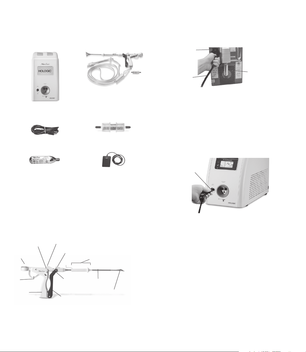
1.3 Screw the CO2 canister into the regulator on the back panel of the
controller until tightened.
Toggle
switch
NOVASURE DISPOSABLE DEVICE
WITH CONNECTING CORD,
NOVASURE
RF CONTROLLER
NOVASURE POWER CORD
NOVASURE CO2 CANISTER NOVASURE FOOT SWITCH
INCLUDING SUCTION LINE
DESICCANT
NOVASURE SUCTION LINE
1.1 The following items are required when using the NovaSure system:
• one sterile, single-patient use NovaSure disposable device with
connecting cord
• one NovaSure RF controller
• one NovaSure foot switch
• one NovaSure AC power cord
• one NovaSure non-sterile suction line desiccant assembly
• one NovaSure CO2 canister.
Lock Release
Button
WIDTH Dial
Suction
Line
Rear
Handle
Cavity Length Setting
Vacuum
Relief Valve
Vacuum
Feedback
Line Barb
Front Handle
Cervical Collar
Sheath
Bipolar
Electrode
Array
NOTE: Please have available at least one extra disposable device,
desiccant assembly and CO2 canister.
AC
power
cord
CO2 canister
1.4 Fully rotate the CO2 regulator knob to the HI position (if equipped).
NOTE: Newer model controllers are not equipped with a knob on the
regulator, thus allowing the CO2 flow to be automatically regulated.
If your controller is not equipped with a regulator knob, proceed to
step1.5.
1.5 Press the toggle switch on the back panel of the controller into the
“on” position.
1.6 Connect the foot switch to the appropriate port on the front panel of
the controller.
Port
NOTE: The first time the Model 10 RFC is turned on, the “Select Your
Language” screen will display. The default setting is in English.
To select another language, press the button with the name
of that language. Save the selection by pressing the flashing
green button.
The language selection will be retained. To change the language
selection after the initial setup, use the “Settings” screen. Press the
name of the language to change the language used on the screen
display. To save changes to the settings, press the flashing green
button. To cancel a selection, press the Blue “X”.
2.0 Procedure
2.1 Prepare the patient for the anesthesia.
2.2 Place patient in dorsal lithotomy position.
2.3 Induce anesthesia according to standard practice.
2.4 Perform bimanual examination. Evaluate for severe anteversion or
retroversion.
10
Page 11

2.5 Prepare and drape patient similar to prep for D&C.
2.6 Insert a speculum into the vagina.
2.7 Grasp the cervix with a tenaculum.
2.8 Take a sound measurement of the uterus to measure the length
from fundus to external cervical os. The efficacy of the NovaSure
system has not been fully evaluated in patients with a uterine
sound measurement greater than 10cm.
2.9 Determine the length of the cervical canal and dilate the canal
for device insertion.
NOTE: The diameter of the NovaSure disposable device is a
nominal 6mm.
2.10 Using the uterine sound and cervical canal measurements, consult
the cavity length table (below) to obtain the appropriate cavity
length settings. On the upper end of the table, dimensions have
been adjusted to reflect the disposable device electrode length.
Correct determination of the cavity length is important for safe and
effective treatment. Overestimating the cavity length may result in
thermal injury to the endocervical canal.
WARNING: Use caution not to perforate the uterine wall when
sounding, dilating or inserting the disposable device.
TABLE 8. CAVITY LENGTH
Uterine Sound (cm)
Cervix
Length
(cm)
2.5 6.5* 6.5* 6.5 6 5.5 5 4.5 4
3.5 6.5 6 5.5 5 4.5 4
4.5 5.5 5 4.5 4
5.5 4.5 4
* The value of 6.5 is not intended to reflect the numerical difference between the sound length
and the length of the cervical canal.
The value 6.5 was entered because it represents the maximum length that the NovaSure
array can be extended.
10 9.5 9 8.5 8 7.5 7 6.5 6
2 6.5* 6.5* 6.5* 6.5 6 5.5 5 4.5 4
3 6.5* 6.5 6 5.5 5 4.5 4
4 6 5.5 5 4.5 4
5 5 4.5 4
6 4
CONTRAINDICATION: Do not treat a patient with a uterine cavity
length that is less than 4 cm, as cervical canal damage may occur.
NOTE: Patients with a uterine cavity length greater than 6.0cm had
observed success rates that were lower than overall study success
rates.
ENGLISH
2.11 Open the sterile NovaSuredisposable device package. Place the
disposable device with the connecting cord into the sterile field
while being careful to keep the non-sterile suction line desiccant
box out of the sterile field.
WARNING: Do not use the sterile single-patient use disposable
device if the packaging appears to be damaged or there is evidence
of tampering.
2.12 Open the non-sterile suction line desiccant box and pouch.
Remove the red caps.
CAUTION: The suction line desiccant is non-sterile and the
packaging should not be placed in the sterile field.
CAUTION: If the suction line desiccant is pink, then replace it prior
to initiating the ablation procedure.
2.13 Connect the desiccant to the barbs on the suction tubing of
disposable device. Ensure the barbs are fully inserted into the
tubing on the desiccant.
2.14 CAUTION: Disposable device must be external to (outside of)
the patient before performing step 2.15.
2.15 Connect the disposable device cord to the appropriate port on the
front panel of the controller.
11
Disposable Device
Port
Page 12

ENGLISH
WARNING: Plugging the NovaSure disposable device into the
NovaSureRFcontroller starts CO2 flow to purge any air out of
the disposable device and tubing. The purging operation takes
approximately 10 seconds and must be performed with the
disposable device external to the patient. The NovaSure RF
controller CAVITY ASSESSMENT LED flashes red (Model 08-09
RFCs) or a purging device message displays (Model 10 RFC) and an
audible pulsed tone sounds throughout the purge procedure. When
the tone and the LED/screen message stop, it is safe to insert the
NovaSure disposable device.
CAUTION: CO2 continuously flows from the time that the disposable
device is plugged into the controller until the CIA portion of the
procedure is complete. To minimize the duration of CO2 flow
and potential risk of embolism, perform the seating procedure
immediately after inserting the disposable device and proceed
directly from the seating procedure to the CIA.
WARNING: Use caution not to perforate the uterine wall when
sounding, dilating or inserting the disposable device.
2.16 Deploy the disposable device outside of the patient and ensure the
controller ARRAY POSITION LED is extinguished (Model 08-09 RFCs)
or the screen message does not display (Model 10 RFC) when the
array is opened. If the LED is not extinguished (Model 08-09 RFCs)
or the screen message is still displayed (Model 10 RFC), close
and open the disposable device again. If this does not resolve the
problem, replace the disposable device.
2.17 Be certain the WIDTH dial reads greater than or equal to 4.0cm.
Lock release
ARRAY
CLOSED
indicator
button
2.19 Make sure the array is completely enclosed by the external sheath.
2.20 Check that the WIDTH dial reads approximately 0.5cm.
2.21 Using the uterine sound measurement and cervical canal
measurements, consult the cavity length table (above) to obtain the
appropriate cavity length settings as described in step 2.10 above.
CONTRAINDICATION: Do not treat a patient with a uterine cavity
length that is less than 4cm, as cervical canal damage may occur.
2.22 Using the cavity length table in section 2.10, select the value
obtained for length into the NovaSure RF controller input screen by
depressing the UP/DOWN arrows.
2.23 Adjust and lock the cavity length setting feature on the disposable
device to the value obtained above. (See step 2.21.) Ensure that the
cervical collar is fully retracted to its proximal position.
WIDTH dial
NOTE: If the WIDTH dial reads less than 4.0cm, close the disposable
device and repeat step 2.16 above. If the WIDTH dial still reads
less than 4.0cm, open a new disposable device and return the old
disposable device to Hologic Technical Support.
2.18 Unlock the disposable device by pressing the lock release button.
Close the disposable device by holding the front handle stationary
and gently pulling the rear handle backwards until the closed array
indicator, located at the hinge of the front and rear handles, reads,
“ARRAY CLOSED”. This indicates that the array has been retracted
into the sheath and the disposable device is in the closed position.
2.24 Confirm that the cervix is dilated to a minimum 6 mm (the nominal
diameter of the NovaSure disposable device).
2.25 Maintain a slight traction on the tenaculum to minimize the angle of
the uterus.
2.26 Angle the disposable device in-line with the axis of the uterus as
the disposable device is inserted transcervically into the uterine
cavity. By holding the front handle, advance the disposable device
until the distal end of the sheath touches the fundus.
12
Page 13

ENGLISH
2.28 Continue to slowly squeeze the disposable device handles together
while gently moving the disposable device ~0.5 cm to and from
the fundus and rotating the handle of the disposable device 45°
counterclockwise from the vertical plane and 45° clockwise from
the vertical plane until the handles lock.
The WIDTH dial should read greater than 2.5 cm.
NOTE: Once the disposable device handles are locked, the uterus
should move in conjunction with the disposable device.
2.29 Gently move the disposable device using anterior, posterior and
lateral movements.
WARNING: If the disposable device is difficult to insert into the
cervical canal, use clinical judgment to determine whether or not
further dilation is required.
2.27 Withdraw the disposable device approximately 0.5 cm from the
fundus. Slowly squeeze the handles (DO NOT LOCK) up to the point
of increased resistance.
The WIDTH dial should read approximately 0.5 cm. At this point, the
external sheath has been retracted.
0.5 cm
2.30 To complete placement, slightly pull back the disposable device
until the WIDTH dial reading reduces by approximately 0.2–0.5cm.
13
Page 14

ENGLISH
2.31 Hold the tenaculum, advance the disposable device slowly and
gently to the fundus. The WIDTH dial should read greater than or
equal to the previous measurement.
2.32 Slide the cervical collar forward using gentle pressure on the tab on
the cervical collar, until the cervical collar forms a seal against the
external cervical os.
Gentle pressure
Slight pressure
2.33 Read the cornu-to-cornu measurement (2.5cm minimum) on the
WIDTH dial indicator.
CONTRAINDICATION: Do not treat a patient with a uterine cavity
width less than 2.5cm, as determined by the WIDTH dial of the
disposable device following device deployment.
CAUTION: If the ARRAY POSITION notification appears, see the
Troubleshooting section under “ARRAY POSITION Alarm.”
2.34 Select the value indicated on the WIDTH dial into the NovaSure RF
controller input screen by depressing the UP/DOWN arrows.
2.35 The system can be operated in either automatic mode or manual
mode. In automatic mode the ablation cycle will start automatically
upon successful completion of the cavity integrity assessment
(CIA). In manual mode the ablation cycle will not start automatically
following a successful CIA.
NOTE: Correct placement of the electrode array against the fundus is important to safe and effective treatment. If part of the electrode array
or the distal edge of the external sheath is seated in the endocervical canal during treatment, there is an increased risk of endocervical
thermal injury.
INCORRECT PLACEMENT
Fundus
Endocervical
Canal
Sheath edge resides in
endocervical canal
Electrode Array
Sheath Edge
14
CORRECT PLACEMENT
Fundus
Electrode Array
Sheath Edge
Endocervical
Canal
Sheath edge resides in
lower uterine segment
Page 15

MODEL 08-09 RF CONTROLLERS MODEL 10 RF CONTROLLER
ENGLISH
Follow next steps on pages 16 through 19. Follow next steps on pages 20 through 23.
Table of Contents for both Models 08-09 and Model 10 RF Controllers
Additional Troubleshooting . . . . . . . . . . . . . . . . . . . . . . . . . . . . . . . . . . . . . . . . . . . . . . . . . . . . . . . . . . . . . . . . . . . . . . . . . . . . . . . . . . . . . . . . . 24
Replacement Instructions . . . . . . . . . . . . . . . . . . . . . . . . . . . . . . . . . . . . . . . . . . . . . . . . . . . . . . . . . . . . . . . . . . . . . . . . . . . . . . . . . . . . . . . . . . 24
Specifications . . . . . . . . . . . . . . . . . . . . . . . . . . . . . . . . . . . . . . . . . . . . . . . . . . . . . . . . . . . . . . . . . . . . . . . . . . . . . . . . . . . . . . . . . . . . . . . . . . . 25
Cleaning and Sanitizing. . . . . . . . . . . . . . . . . . . . . . . . . . . . . . . . . . . . . . . . . . . . . . . . . . . . . . . . . . . . . . . . . . . . . . . . . . . . . . . . . . . . . . . . . . . . 28
Parts List . . . . . . . . . . . . . . . . . . . . . . . . . . . . . . . . . . . . . . . . . . . . . . . . . . . . . . . . . . . . . . . . . . . . . . . . . . . . . . . . . . . . . . . . . . . . . . . . . . . . . . . 28
Warranty . . . . . . . . . . . . . . . . . . . . . . . . . . . . . . . . . . . . . . . . . . . . . . . . . . . . . . . . . . . . . . . . . . . . . . . . . . . . . . . . . . . . . . . . . . . . . . . . . . . . . . . 29
Technical Support and Product Return Information. . . . . . . . . . . . . . . . . . . . . . . . . . . . . . . . . . . . . . . . . . . . . . . . . . . . . . . . . . . . . . . . . . . . . . 29
Symbol Definitions. . . . . . . . . . . . . . . . . . . . . . . . . . . . . . . . . . . . . . . . . . . . . . . . . . . . . . . . . . . . . . . . . . . . . . . . . . . . . . . . . . . . . . . . . . . . . . . . 30
15
Page 16

ENGLISH
Model 08-09 RFC USERS ONLY
Operating the Model 08-09 RF Controllers
A. Automatic mode
To operate the system in automatic mode, press the ENABLE
button prior to beginning the Cavity Integrity Assessment (CIA).
Proceed to step 2.36, but do not follow step 2.37 if operating the
system in automatic mode.
B. Manual mode
To operate the system in the manual mode, do not press the
ENABLE button prior to beginning the Cavity Integrity Assessment
(CIA). Follow steps 2.36 and 2.37.
2.36 Begin the CIA procedure by stepping on the foot switch once.
The CAVITY ASSESSMENT LED flashes green in conjunction with
an audible tone at a rate of once per second when the system
is performing a CIA. The duration of the test will range between
approximately 7 and 30seconds. A steady green LED appears
when the CIA has passed and the system can deliver RF energy.
Power cannot be applied to the disposable device until the CAVITY
ASSESSMENT LED is a steady green light.
If the cavity integrity assessment fails, then the CAVITY
ASSESSMENT LED on the NovaSure RF controller will flash red,
and a rapid audible tone will sound at a rate of four times per
second.
cervical collar, use another tenaculum to grasp the cervix around the
sheath. Repeat the CIA by pressing the foot switch.
NOTE: CO2 leakage may occur at the external cervical os due to the
presence of an over-dilated cervix. Visible bubbles or the “hissing”
sound of escaping gas may accompany CO2 leakage under either of
these conditions.
C. If the cavity integrity assessment fails after reasonable attempts to
implement the troubleshooting procedures (step 2.36), abort the
procedure.
NOTE: Removing the disposable device from the uterine cavity after
completing a cavity integrity assessment will require an additional
CIA test to be performed upon disposable device re-insertion
(whether or not the CIA previously passed) prior to initiating an
ablation.
2.37 Manual mode only
When operating the system in manual mode, the ablation cycle
will not start automatically after the successful completion of the
CIA. Once a successful CIA has been completed, press the ENABLE
button and depress the foot switch a second time to initiate the
ablation cycle.
NOTE: In some Model 09 RF controllers, a vacuum pre-check
occurs automatically prior to initiation of the ablation cycle. The
VACUUM LED will flash and an audible tone will be heard for up to
10seconds during the vacuum pre-check.
MANUAL MODE
If the cavity integrity assessment fails, press the foot switch to stop the
sound. Next:
A. If a perforation is suspected, the procedure should be terminated
immediately.
B. If the CIA test fails again, check for leaks in the system, and between
the cervix and cervical collar. Be sure to check all tubing connections,
and ensure that a suction line desiccant has been installed. If the
leak appears to be at the cervix and cannot be resolved by using the
During the ablation cycle, a blue RF ON LED will illuminate. At the
completion of the ablation cycle, the RF power delivery (RF ON
LED), as well as suction, will switch off automatically. The physician
can stop the progress of the procedure at any time by depressing
the foot switch.
NOTE: RF power delivery can be stopped at any time by pressing
the foot switch
2.38 After automatic termination of the ablation cycle (approximately
90seconds), fully retract the cervical collar by using the tab on
the cervical collar. Fully retract the cervical collar by sliding it to its
proximal position.
16
Page 17

CAUTION: The cervical collar must be fully retracted to its proximal
position in order to minimize the potential for damage to the sheath
when closing the array.
Cervical
Collar
2.39 Unlock the disposable device by pressing the lock release button.
Close the disposable device by holding the front handle stationary
and gently pulling the rear handle backwards until the closed array
indicator, located at the hinge of the front and rear handles, reads
“ARRAY CLOSED”. This indicates that the array has been retracted
into the sheath and the disposable device is in the closed position.
(See step2.18.)
NOTE: If it is difficult to close and remove the disposable device,
see the Troubleshooting section, “Difficulty closing and removing
the disposable device post-ablation.”
CAUTION: To avoid damaging the device, employ gentle technique
when retracting the array.
2.40 Withdraw the disposable device from the patient.
2.41 Turn off the NovaSure RF controller. Close the CO2 regulator.
2.42 Perform postoperative patient care according to standard
procedures. The used disposable device must be treated as
ENGLISH
biohazardous waste and disposed of according to standard
practices of the hospital or clinic where the treatment is
performed.
2.43 Discharge the patient from the hospital or office as indicated
by the managing physician.
Periodic Maintenance and Service
There is no service manual for the NovaSure RF controller since
there are no field serviceable components within the unit.
WARNING: No modification of this equipment is allowed.
Periodic maintenance
The RF controller has been designed and tested to meet IEC
60601-1 and other safety standards. Maintenance is not required
as the system performs self-checks when power is turned on. To
clean the controller refer to the “Cleaning and Sanitizing” section.
RF power output test
The NovaSure RF controller Model 08-09 integrates automatic
power output testing into a power on self test (POST). During the
POST the controller’s power output (Pc) is delivered into a shunt
resistor (Rs) located inside the controller. Pc is targeted to be 180
watts and Rs is nominally 25ohms. During the POST, no power
is delivered to the disposable device connector at the front of the
controller.
NOTE: If a NovaSure disposable device is connected at
the time the controller is powered up, the POST will not be
performed and the controller will return to normal operation. If
a device is connected during the POST sequence, the POST will
terminate and the controller will return to normal operation.
The following procedure is used to execute the POST and display
the actual value of Pc and Rs determined:
1. With the switch on the power input module in the off position,
check to make sure a disposable device is not connected to the
RFcontroller.
2. Depress and hold the length UP and length DOWN arrows
simultaneously, then toggle the power switch at the power input
module while continuing to depress the arrows. This step initiates
the POST, which proceeds automatically.
3. Upon the completion of the POST (approximately 5 seconds), the
RFcontroller will generate one audible tone, and then display the
actual value of Pc for two seconds on the power set LED.
4. After two seconds elapse, the power set LED will change to display
the actual value of Rs for two seconds.
5. The power set LED will then change to 00, and the RF controller will
return to normal operation without further input from the user.
The acceptable limits on Pc= 180W ±10%. If Pc is not within
specification, a system fault will occur. The actual value of Rs is for
reference only.
Model 08-09 RFC USERS ONLY
17
Page 18

ENGLISH
Model 08-09 RFC USERS ONLY
NOTE: If a system fault occurs during the POST, toggle off the
power at the power input module and repeat the POST. If a
system fault occurs a second time, remove the RFcontroller
from service and contact Hologic customer service.
CAUTION: Do not attempt to repair the controller if problems
are suspected. Follow the troubleshooting guide in this
manual. If problems persist, call Hologic Technical Support
for instructions.
Sterile NovaSure disposable device: No maintenance is necessary.
Single-patient use only. Do not reuse or re-sterilize the NovaSure
disposable device.
NovaSure RF Controller LED Descriptions
The following is a description of the alert LEDs on the
NovaSureRFcontroller.
CAVITY ASSESSMENT LED: illuminates in four modes:
1. Flashes red in conjunction with an audible tone at a rate of
once per second for the first 10seconds when the system is
purging air out of the disposable device. After 10seconds, the LED
and audible tone will cease, although CO2 will continue to flow out
of the vacuum feedback line.
2. Flashes green in conjunction with an audible tone at a rate of
once per second when the system is performing a cavity integrity
assessment.
3. Steady green light appears when the cavity integrity
assessment has passed and the system can deliver RF energy.
Power cannot be applied to the disposable device until the CAVITY
ASSESSMENT LED is a steady green.
4. Steady red lights and an audible tone at a rate of four times
per second occur when the cavity integrity assessment has failed.
The CIA test may be tried again.
ENABLE LED: illuminates amber when the user presses the
ENABLE button. Acts as a safety so that the NovaSure disposable
device will not accidentally activate when the foot switch is
touched. The ENABLE LED will not illuminate when the ARRAY
POSITION LED is on.
RF ON LED: illuminates blue when the ablation is proceeding
(the foot switch has been depressed to activate the
NovaSureRFcontroller with the NovaSure disposable device array
in place in the uterus).
PROCEDURE COMPLETE LED: illuminates when the tissue impedance
reaches 50ohms and the ablation procedure runs a minimum of
30seconds.
ARRAY POSITION LED: illuminates red when one pole of the electrode
array may be in contact with another. This LED should be illuminated
when the array is not fully deployed. The ENABLE LED cannot be toggled
on, nor can power be delivered to the array when the ARRAY POSITION
LED is illuminated.
VACUUM LED: illuminates in two conditions:
1. Flashes red accompanied by an audible tone while the system is
stabilizing the vacuum level for up to 10seconds before energy
delivery commences (only for Model09 controllers with a vacuum
pre-check function).
2. Illuminates red when the vacuum relief valve is stuck in the closed
position, when a blockage is detected in the disposable device or the
connection tubing or when the system has a leak. Such a situation
might be created by:
• an over-dilated cervix with poor contact between the cervical collar
and the external os;
• a poor attachment of the desiccant tube to the suction tubing;
• an obstruction in the disposable device tubing; or
• an obstruction in the disposable device.
SYSTEM FAULT LED: illuminates red if the system faults or if there is a
self-diagnostic check failure with the system clock or power delivery. If
this event occurs, terminate the procedure immediately and contact an
authorized Hologic service representative for instructions.
Troubleshooting Most Common Alarms
CAVITY ASSESSMENT LED illuminated red
If the CAVITY ASSESSMENT LED is steady red, the cavity integrity
assessment has failed. If the cavity integrity assessment fails, then the
CAVITY ASSESSMENT LED on the NovaSure RF controller will flash red,
and a rapid audible tone will sound at a rate of four times per second.
The CIA test may be tried again.
If a perforation is suspected, the procedure should be terminated
immediately.
If the cavity integrity assessment fails, press the foot switch to stop the
sound. The cause of the cavity integrity assessment failure is the inability
to pressurize the cavity. It may be caused by:
1. Device leak: ensure that the suction line desiccant filter has been
installed. Check all tubing connections to ensure that they are tightly
connected.
2. Leak at the external os of the cervix: Look for visible bubbles or a
“hissing” sound at the external os of the cervix.
Use the tab on the cervical collar to advance the cervical collar
towards the external os of the cervix to ensure there is a tight seal.
Test again. If the test fails again, use a second tenaculum to grasp
the cervix around the sheath of the NovaSure disposable device. Test
again.
3. Uterine perforation: If a uterine perforation is suspected, the
procedure should be terminated immediately.
NOTE: CO2 leakage may occur at the external cervical os due to the
presence of an over-dilated cervix. Visible bubbles or the “hissing”
sound of escaping gas may accompany CO2 leakage under either of
these conditions.
18
Page 19

If the cavity integrity assessment fails after reasonable attempts to
implement the troubleshooting procedures (step 2.36), abort the
procedure.
NOTE: Removing the disposable device from the uterine cavity after
completing a cavity integrity assessment will require an additional
CIA test to be performed upon disposable device re-insertion
(whether or not the CIA previously passed) prior to initiating an
ablation.
VACUUM LED illuminated
The VACUUM LED illuminates when the vacuum level is outside its
specified range. This can occur as a result of one or more of the
following:
• an over-dilated cervix;
• poor contact between the cervical collar and the external cervical os;
• the vacuum relief valve is in the closed position;
• an obstruction in the disposable device filter(s) (two) or desiccant; or
• an obstruction within the disposable device.
To eliminate this condition, perform the following:
• Gently press a 2–3.5mm uterine dilator or sound inside the vacuum
relief valve.
• Check the cervical collar position, and reposition it if necessary. Use
the tab on the cervical collar to advance the cervical collar towards the
external os of the cervix to ensure there is a tight seal. Verify that air is
not being drawn through the cervix by a loose fit between the cervical
collar and the entrance to the cervical canal. If air is being drawn in
through the cervical canal, try to reposition the cervical collar and
disposable device shaft to prevent air ingress.
• Ensure the suction canister on the disposable device is vertical and the
device tubing is not draped over the patient’s leg.
• Check all tubing connections to ensure that they are tightly connected.
Check the push-on tubing connectors at the desiccant tube. Replace
the dessicant if it is pink. Ensure that the filter located near the
disposable connection on the vacuum feedback line is tightened.
• Reattempt ablation.
If the VACUUM LED illuminates again:
• Disconnect the disposable device from the RF controller.
• Remove the disposable device from the patient, then;
• Exchange the disposable device with a new disposable device.
• Reattempt the ablation with the new device.
If a vacuum alarm occurs with the new device, abort the procedure:
NOTE: Removing the disposable device from the uterine cavity after
completing a cavity integrity assessment will require an additional
CIA test to be performed upon disposable device re-insertion
(whether or not the CIA previously passed) prior to initiating an
ablation.
ENGLISH
CO2 canister low or empty
The NovaSure RF controller will generate an audible tone at a rate
of four times per second during this alarm condition. LEDs that
were illuminated prior to the alarm will remain in the same state
during the low CO2 event. Pressing the foot switch will not turn off
the audible alarm.
1. Replace the CO2 canister to stop the audible tone.
NOTE: It is not necessary to remove the disposable device
from the patient prior to replacing the canister.
2. Continue with the procedure.
ARRAY POSITION LED illuminated
1. Gently move the proximal end of the disposable device and
observe if the ARRAY POSITION LED extinguishes. If it does not,
proceed with the following:
2. Attempt gentle reseating of the NovaSure disposable device:
A. Partially retract the array into the sheath by releasing the
disposable device handle lock release button;
B. Pull the disposable device back slightly from fundus;
C. Slowly redeploy the disposable device array while gently
rocking the disposable device back and forth and locking
the disposable device handles; and
D. Reseat the disposable device against fundus using the
seating procedure described in steps 2.26 through 2.33.
3. If the uterus is retroverted, take special care to avoid
perforation. Apply gentle caudad traction to the cervix with the
tenaculum, and elevate the disposable device handle upward
toward the ceiling (in-line with the axis of the uterus) while
performing the seating procedure.
4. If the ARRAY POSITION LED is still illuminated, fully retract the
disposable device array and remove the disposable device
from the patient.
5. Deploy the disposable device outside the patient’s body; ensure the
electrode array is undamaged and that the ARRAY POSITION LED
extinguishes.
6. Attempt reinsertion, redeployment and reseating of the disposable
device using the seating procedure described in section 2.0.
7. If the ARRAY POSITION LED remains illuminated, replace with a new
disposable device.
8. If the ARRAY POSITION LED remains illuminated with a new
disposable device, terminate the procedure.
Model 08-09 RFC USERS ONLY
Please turn to page 24 for the remainder of
the Instructions for Use.
19
Page 20

ENGLISH
Model 10 RFC USERS ONLY
Operating the Model 10 RF Controller
A. Automatic mode
To operate the Model 10 RFC in Automatic Mode, press the
“Switch Mode” button when it appears at the bottom of the
screen. Proceed to step 2.36, but do not follow step 2.37 if
operating the system in automatic mode.
B. Manual mode
NOTE: Manual Mode is the default system operation.
To operate the system in manual mode, do not press the “Switch
Mode” button prior to beginning the cavity integrity assessment
(CIA). Follow steps 2.36 and 2.37.
2.36 Begin the CIA procedure by stepping on the foot switch once.
“Cavity Assessment in Progress” will display on the screen while
five dots light off and on sequentially. The duration of the test
will range between approximately 7 and 30 seconds. A “Cavity
Assessment Complete” screen displays when the CIA has passed
and the system can deliver RF energy. Power cannot be applied to
the disposable device until the CIA Complete screen displays.
If the cavity integrity assessment fails, a screen will display
“Cavity Assessment Failure” with troubleshooting steps.
A. If a perforation is suspected, the procedure should be
terminated immediately.
B. If the CIA test fails again, check for leaks in the system, and
between the cervix and cervical collar. Be sure to check all tubing
connections, and ensure that a suction line desiccant has been
installed. If the leak appears to be at the cervix and cannot be
resolved by using the cervical collar, use another tenaculum
to grasp the cervix around the sheath. Repeat the CIA test by
pressing the foot switch.
NOTE: CO2 leakage may occur at the external cervical os due to the
presence of an over-dilated cervix. Visible bubbles or the “hissing”
sound of escaping gas may accompany CO2 leakage under either of
these conditions.
C. If the cavity integrity assessment fails after reasonable attempts to
implement the troubleshooting procedures (step 2.36), abort the
procedure.
NOTE: Removing the disposable device from the uterine cavity after
completing a cavity integrity assessment will require an additional
CIA test to be performed upon disposable device re-insertion
(whether or not the CIA previously passed) prior to initiating an
ablation.
2.37 Manual Mode Only
When operating the system in manual mode, the ablation cycle
will not start automatically after the successfully completion of the
cavity integrity assessment (CIA). Once a successful CIA has been
completed, press the ENABLE button and depress the foot switch a
second time to initiate the ablation cycle.
NOTE: In all Model 10 RF controllers, a vacuum pre-check occurs
automatically prior to initiation of the ablation cycle. A “Vacuum
Check in Progress” screen will appear and an audible tone will be
heard for up to 10 seconds during the vacuum pre-check.
During the ablation cycle, an “RF ON” screen with a timer will
appear to track the duration of the ablation.
NOTE: RF power delivery can be stopped at any time by pressing
the foot switch.
2.38 After automatic termination of the ablation cycle (approximately 90
seconds), fully retract the cervical collar to its proximal position by
using the tab on the cervical collar.
CAUTION: The cervical collar must be fully retracted to its proximal
position in order to minimize the potential for damage to the sheath
when closing the array.
Cervical
Collar
20
Page 21

At the completion of the ablation cycle, a “Procedure Complete” screen
will appear with a summary of the procedure. The “Procedure Complete”
screen will capture the following information for each procedure:
• Cavity Length
• Cavity Width
• Power Level
• RF Ablation Time
2.39 Unlock the disposable device by pressing the lock release button.
Close the disposable device by holding the front handle stationary
and gently pulling the rear handle backwards until the closed array
indicator, located at the hinge of the front and rear handles, reads
“ARRAY CLOSED”. This indicates that the array has been retracted
into the sheath and the disposable device is in the closed position.
NOTE: If it is difficult to close and remove the disposable device,
see the Troubleshooting section, “Difficulty closing and removing
the disposable device post-ablation”.
CAUTION: To avoid damaging the device, employ gentle technique
when retracting the array.
2.40 Withdraw the disposable device from the patient.
ENGLISH
Periodic maintenance
The RF controller has been designed and tested to meet IEC
60601-1 and other safety standards. Maintenance is not required
as the system performs self-checks when power is turned on.To
clean the controller refer to the “Cleaning and Sanitizing” section.
RF power output test
The NovaSure RF controller Model 10 integrates automatic power
output testing in a power on self test (POST). During the POST the
controller’s power output (Pc) is delivered into a shunt resistor (Rs)
located inside the controller. Pc is targeted to be 180 watts and Rs
is nominally 25 ohms. During the POST, no power is delivered to
the disposable device connector at the front of the controller.
The NovaSure RF controller Model 10 performs POST
automatically upon power up. To access POST information, go to
Settings and scroll to System Information. Press the “View Info.”
button.
NOTE: If a system fault occurs during the POST, toggle off the
power at the power input module and repeat the POST. If a
system fault occurs a second time, remove the RF controller
from service and contact Hologic customer service.
CAUTION: Do not attempt to repair the controller if problems
are suspected. Follow the troubleshooting guide in this
manual. If problems persist, call Hologic Technical Support for
instructions.
Sterile NovaSure disposable device: No maintenance is necessary.
Single-patient use only. Do not reuse or re-sterilize the NovaSure
disposable device.
Model 10 RFC USERS ONLY
2.41 TURN OFF THE NOVASURE RF CONTROLLER.
2.42 Perform postoperative patient care according to standard
procedures. The used disposable device must be treated as
biohazardous waste and disposed of according to standard
practices of the hospital or clinic where the treatment is performed.
2.43 Discharge the patient from the hospital or office as indicated by the
managing physician.
Periodic Maintenance and Service
There is no service manual for the NovaSure RF Controller since there
are no field serviceable components within the unit.
WARNING: No modification of this equipment is allowed.
NovaSure Model 10 RF Controller Screen Icons
The following is a description of the icons on the NovaSure Model 10 RF
controller screen.
Settings Icon:
Press this button to display the
setting options for Language,
Brightness, and Volume.
Help Icon:
Press this button to display more information
regarding the current step of the procedure.
This icon will display an abridged version of
the IFU language.
21
Last Procedure Icon:
Press this button to display the
“Procedure Complete” Screen
and review the summary from
the last procedure.
Page 22

ENGLISH
Model 10 RFC USERS ONLY
NOTE: When the “Last Procedure” Icon is pressed, only
the previous procedure will be displayed. Information for
procedures prior to the most recent procedure will not be
available.
NOTE: In the “Settings” screen, press the “-” or “+” buttons
to adjust the volume and brightness.
NOTE: The first time the Model 10 RFC is turned on, the
“Select Your Language” screen will display. The default
setting is in English. To select another language, press the
button with the name of that language. Save the selection by
pressing the flashing green button. The language selection
will be retained. To change the language selection after the
initial setup, use the “Setting” screen. Press the name of the
language to change the language used on the screen display.
To save changes to the settings, press the flashing green
button. To cancel a selection, press the blue “X”.
Troubleshooting Most Common Alarms
CAVITY ASSESSMENT ALARM
If the cavity integrity assessment fails, a screen will display
“Cavity Assessment Failure” with an abridged version of the
troubleshooting tips below. The cause of the cavity integrity
assessment (CIA) failure is the inability to pressurize the cavity. It
may be caused by:
1. Device leak: Ensure that the suction line desiccant filter has been
installed. Check all tubing connections to ensure that they are tightly
connected.
2. Leak at the external os of the cervix: Look for visible bubbles or a
“hissing” sound at the external os of the cervix.
Use the tab on the cervical collar to advance the cervical collar
towards the external os of the cervix to ensure there is a tight seal.
Perform the CIA test again. If the CIA test fails again, use a second
tenaculum to grasp the cervix around the sheath of the NovaSure
disposable device. Perform the CIA test again.
3. Uterine perforation: If a perforation is suspected, the procedure
should be terminated immediately.
NOTE: CO2 leakage may occur at the external cervical os due to the
presence of an over-dilated cervix. Visible bubbles or the “hissing”
sound of escaping gas may accompany CO2 leakage under either of
these conditions.
NOTE: When following the troubleshooting steps on the Model 10
RFC, press the “?” button on the screen and use the scroll buttons
on the right for more information. To get back to the main screen
from the additional troubleshooting tips, press the “X” in the top
right corner of the screen.
If the cavity integrity assessment fails after reasonable attempts
to implement the troubleshooting procedure (step 2.36), abort the
procedure.
VACUUM ALARM
The Vacuum alarm occurs when the vacuum level is outside its specified
range. This can occur as a result of one or more of the following:
• An over-dilated cervix;
• Poor contact between the cervical collar and the external cervical os;
• The vacuum relief valve is in the closed position;
• An obstruction in the disposable device filter(s) (two) or desiccant; or
• An obstruction within the disposable device.
If the Vacuum check fails, a screen will display “Vacuum Failure” with an
abridged version of the following troubleshooting tips:
• Gently press a 2-3.5 mm uterine dilator or sound inside the vacuum
relief valve
• Check the cervical collar position, and reposition if necessary. Use the
tab on the cervical collar to advance the cervical collar towards the
external os of the cervix to ensure there is a tight seal. Verify that air is
not being drawn through the cervix by a loose fit between the cervical
collar and the entrance to the cervical canal. If air is being drawn in
through the cervical canal, try to reposition the cervical collar and
disposable device shaft to prevent air ingress.
• Ensure the suction canister on the disposable device is vertical and the
device tubing is not draped over the patient’s leg.
• Check all tubing connections to ensure that they are tightly connected.
Check the push-on tubing connectors at the desiccant tube. Replace
the desiccant if it is pink. Ensure that the filter located near the
disposable connection on the vacuum feedback line is tightened.
• Reattempt ablation.
If the “Vacuum Failure” screen displays again:
• Disconnect the disposable device from the RF controller.
• Remove the disposable device and replace with a new disposable
device.
• Reattempt the ablation with the new device.
22
Page 23

NOTE: When following the troubleshooting steps on the Model 10
RFC, press the “?” button on the screen and use the scroll buttons
on the right for more information. To get back to the main screen
from the additional troubleshooting tips, press the “X” in the top
right corner of the screen.
If the vacuum alarm occurs with the new device, abort the procedure.
NOTE: Removing the disposable device from the uterine cavity after
completing a cavity integrity assesment will require an additional
CIA test to be performed upon disposable device re-insertion
(whether or not the CIA previously passed) prior to initiating an
ablation.
CO2 canister low or empty
A screen will display “Replace CO2” with an image of the back of the
controller. An audible tone will be generated at a rate of 1 time per
second. Alarm messages that were present prior to the alarm will remain
in the same state during the replace CO2 event. Pressing the foot switch
will not turn off the audible alarm.
1. Replace the CO2 canister to stop the audible tone.
NOTE: It is not necessary to remove the disposable device from the
patient prior to replacing the canister.
2. Continue with the procedure.
ARRAY POSITION Alarm
The Array Position message displays when the array is not open fully.
The controller cannot perform ablation when Array Position message
displays. If the ARRAY POSITION alarm occurs, a screen will display
“Check Array” with an abridged version of the following troubleshooting
tips:
1. Gently move the proximal end of the disposable device and observe
if the Array Position message no longer displays. If it still displays,
proceed with the following:
2. Attempt gentle reseating of the NovaSure disposable device:
A. Partially retract the array into the sheath by releasing the
disposable device handle lock release button;
B. Pull the disposable device back slightly from the fundus;
C. Slowly redeploy the disposable device array while gently
rocking the disposable device back and forth and locking the
disposable device handles; and
D. Reseat the disposable device against the fundus using the
seating procedure described in steps 2.26 through 2.33.
3. If the uterus is retroverted, take special care to avoid perforation.
Apply gentle caudad traction to the cervix with the tenaculum, and
elevate the disposable device handle upward toward the ceiling
(in-line with the axis of the uterus) while performing the seating
procedure.
ENGLISH
4. If the Array Position message still displays, fully retract the
disposable device array and remove the disposable device
from the patient.
5. Deploy the disposable device outside the patient’s body;
ensure the electrode array is undamaged and that the Array
Position message no longer displays.
6. Attempt reinsertion, redeployment and reseating of the
disposable device using the seating procedure described in
section 2.0.
7. If the Array Position message still displays, replace with a new
disposable device.
8. If the Array Position message displays with a new disposable
device, terminate the procedure.
NOTE: When following the troubleshooting steps on the Model
10 RFC, press the “?” button on the screen and use the scroll
buttons on the right for more information. To get back to the
main screen from the additional troubleshooting tips, press
the “X” in the top right corner of the screen.
Please turn to next page 24 for the
remainder of the Instructions for Use.
Model 10 RFC USERS ONLY
23
Page 24

ENGLISH
INSTRUCTIONS FOR USE ALL USERS
Additional Troubleshooting
Suspected uterine perforation
Prior to Application of Energy:
1. Terminate the procedure
2. Assure patient stability
3. Consider work-up for
perforation
4. Reschedule procedure,
if appropriate
Array does not fully deploy and lock in uterus
1. Partially retract array into sheath (hold the front handle
stationary and pull the rear handle back and away from the
patient);
2. Reposition the disposable device in the cavity;
3. Redeploy the array in cavity;
4. If the disposable device does not lock, remove it from the
uterus;
5. Inspect the disposable device for damage;
6. Attempt to open the disposable device and lock it outside the
patient;
7. If damaged, the replace disposable device;
8. If the disposable device is not damaged, reinsert it into the
patient’s uterine cavity and attempt deployment; and
9. If unable to deploy the disposable device to a minimum 2.5cm
cornu-to-cornu distance, terminate the procedure.
10. Consider uterine perforation as a possible cause for not
deploying.
Difficulty closing and removing the disposable device
post-ablation
Confirm that the lock release button is depressed:
• If so, gradually withdraw the disposable device from the
patient.
• If not, press the lock release button and reattempt to close the
disposable device. If it is still difficult to close, gradually withdraw
the disposable device from the patient.
ENABLE LED will not illuminate (Model 08-09 RFCs only)
Be sure:
1. The ENABLE button is firmly depressed;
2. The NovaSure RF controller is plugged in;
3. The toggle switch at the back of the controller is on; and
4. The ARRAY POSITION LED is not illuminated.
During or after Application of
Energy:
1. Terminate the procedure
2. Assure patient stability
3. Rule out visceral injury
4. Reschedule procedure,
if appropriate
PROCEDURE COMPLETE LED not illuminated (Model 08-09 RFCs)
or “Procedure Complete” Screen does not appear (Model 10
RFC) at the end of a procedure
1. If power has not been applied for at least 30 seconds, the LED will
not illuminate (Model 08-09 RFCs) or the “Procedure Complete”
Screen will not appear (Model 10 RFC). Remove the NovaSure
disposable device from the uterus after fully retracting the disposable
device array into the sheath:
A. Release the disposable device lock release button;
B. Hold the disposable device front handle steady; and
C. Pull the disposable device rear handle backward.
2. Inspect the disposable device for any damage. Fully deploy the
electrode array outside the patient, demonstrating that the ARRAY
POSITION LED does not illuminate (Model 08-09 RFCs) or that the
message does not display (Model 10 RFCs).
3. If the disposable device is not damaged and the ARRAY POSITION
LED extinguishes (Model 08-09 RFCs) or the message screen
does not appear (Model 10 RFC), reinsert, redeploy and reattempt
treatment.
4. If the problem persists, replace the disposable device with a new
disposable device.
5. Reattempt the procedure. If the problem persists, terminate the
procedure.
RF ON LED will not illuminate (Model 08-09 RFCs) or the “RF
ON” screen will not appear (Model 10 RFC)
1. If the NovaSure RF controller is plugged in, switched on, the ENABLE
button has been pressed and no power is delivered from the
controller when the foot switch is depressed, check the foot switch
connection. Also make sure the CAVITY ASSESSMENT has passed.
2. If the problem persists, terminate the procedure.
UP/DOWN values will not appear when pressing the appropriate
buttons
Make sure that the disposable device is connected to the controller.
The values will not appear unless the disposable device is properly
connected to the controller.
Replacement Instructions
The NovaSure RF controller uses a pair of fuses that are located on
a fuse carrier in the power input module. Type T5AH, 250V fuses are
used. The module can be accessed by using a slotted screwdriver to
pop open the fuse carrier door. If required, the fuse carrier may then be
removed and the fuses changed. Assembly is the reverse of these steps.
Any potentially defective NovaSure product must be returned to Hologic
for evaluation. Follow the instructions at the end of this manual in the
Service Returns section, for obtaining a returned materials authorization
number (RMA #). Do not discard the NovaSure disposable device.
NovaSure disposable device
1. The NovaSure disposable device does not contain latex.
24
Page 25

2. The NovaSure disposable device is a Class III device by FDA
regulation.
3. The NovaSure disposable device is a Class IIB device according to
the MDD93/42/EEC.
4. The NovaSure disposable device tip nominal diameter: 6mm.
5. The NovaSure disposable device overall dimensions:
19” x 6” x 12” (48.3cm x 15.2cm x 5cm).
6. The NovaSure disposable device has a voltage rating of 153V.
NovaSure RF controller
1. The NovaSure RF controller can be used with outlets providing 100 to
240 VAC and will draw a maximum of 5 Amps.
2. The NovaSure RF controller is a Class I, defibrillator-proof Type BF
instrument, according to IEC 60601-1.
3. The NovaSure RF controller is a Class III device by FDA regulation.
4. The NovaSure RF controller is a Class IIB device according to the
MDD93/42/EEC.
5. The RF controller has been tested and found to comply with the
limits for medical devices according to IEC 60601-1-2 ED 4.0: 2014.
These limits are designed to provide reasonable protection against
harmful interference in a typical medical installation. This equipment
generates, uses and can radiate radio frequency energy and, if not
installed and used in accordance with the instructions, may cause
harmful interference to other devices in the vicinity. However, there
is no guarantee that interference will not occur in a particular
installation. If this equipment does cause harmful interference to
other devices, which can be determined by turning the equipment off
and on, the user is encouraged to try to correct the interference by
one or more of the following measures:
• Re-orient or relocate the receiving device
• Increase the separation between equipment
• Connect the equipment into an outlet on a circuit different from that
to which the other device(s) is/are connected.
• Contact Hologic Technical Support (or the manufacturer of the other
equipment) for assistance.
6. The controller meets the requirements of IEC60601-1/UL60601-1,
IEC60601-2-2 and CSAC22.2No.601.1.
7. Shipment of the controller should be done only in the original Hologic
packaging. Environmental requirements for use, shipping and
storage are indicated below.
8. The absolute maximum peak voltage generated by the
NovaSureRFcontroller is 153volts. Accessories used with the RF
controller should have a voltage rating equal to or greater than
153volts.
9. The absolute maximum peak power generated by the
NovaSureRFcontroller is 216 watts.
10. NovaSureRFcontroller weight: 24lbs (11kg), unpacked.
11. Height: 12.5”; Width: 7.5”; Depth: 14.5”
(32cm x 19cm x 35.5cm).
12. The maximum pressure of CO2 delivered from the NovaSure RF
controller and disposable device shall be 90 ±10mmHg.The
maximum flow rate of CO2 from the NovaSure RF controller
connected to the disposable device shall be 95 ±15ml/
min. (The maximum flow rate of CO2 from the NovaSureRF
controller without a NovaSure disposable device attached is
117±13ml/ min.)
13. The Novasure RF Generator should be used without a neutral
electrode.
Power vs. Resistance
Measured Power (Watts)
Load Resistance (Ohms)
Actual Power vs. Power Setting into a 20 Ohm Load
Actual Power (Watts)
Power Setting (Ohms)
Operating, non-packaged conditions
Altitude 0 to 10,000ft (0 to 3,030m)
Temperature 10°C to 40°C (50°F to 104°F)
Humidity 15 to 85% RH at 40°C (non-condensing)
Non-operating, packaged conditions
Altitude 0 to 40,000 ft (0 to12,120 m)
Temperature –30°C to 60°C (–22°F to 140°F)
Humidity 85% RH, 72 hr, at 38°C (non-condensing)
ENGLISH
INSTRUCTIONS FOR USE ALL USERS
25
Page 26

ENGLISH
INSTRUCTIONS FOR USE ALL USERS
Essential Performance:
• Air must be purged from the device for 10 seconds prior to
insertion in patient.
• The Cavity Integrity Assessment (CIA) must measure a pressure
of 50 ± 10 mm of Hg for 3 seconds minimum to pass. Otherwise
the CIA will report an error. The RF controller will not enable an
ablation to begin until CIA passes.
• RF power: The range of RF power delivery is 55 to 180 (+/-20%)
watts.
• Vacuum pressure monitoring: During an ablation the vacuum
pressure must be in the range of 0.7 ±0.2 in Hg to 6 ±1.0 in Hg.
If the vacuum pressure exceeds this range, the controller will end
the ablation.
• Impedance monitoring: The RF Controller will end an ablation
when the measured tissue impedance reaches 50 ohms. The
controller also will act the same if the impedance is measured as
less than 0.5 ohms.
• Two minute timer: After two minutes of RF energy delivery, the
controller will end the ablation
• Ten minute timeout: after completing the ablation procedure the
controller times out for 10 minutes, during which the controller is
incapable of delivering energy.
• DC Short Circuit protection: If the RF controller detects a short
circuit (i.e. <13+/-6ohms), the ablation will be ended.
Guidance and manufacturer’s declaration –
electromagnetic emissions and immunity
The NovaSure RF controller is intended for use in the
electromagnetic environment specified below. The customer
or user of the NovaSure RF controller should ensure that it is
used in such an environment.
Electromagnetic emissions
Emissions
Test
RF
Emissions
CISPR 11
RF
Emissions
CISPR 11
Harmonic
emissions
IEC
61000-3-2
Voltage
fluctuations/
flicker
emissions
IEC
61000-3-3
Compliance Electromagnetic Environment –
Guidance
Group 1 The NovaSure RF controller must emit
electromagnetic energy in order to
perform its intended function. Nearby
electronic equipment may be affected.
Class A The NovaSure RF controller is intended
for use in Professional Healthcare
Facilities including hospitals and
Class A
Complies
physician’s offices.
WARNING: The EMISSIONS
characteristics of this equipment
make it suitable for use in industrial
areas and hospitals (CISPR 11 Class
A). If it is used in a residential
environment (for which CISPR 11
Class B is normally required) this
equipment might not offer adequate
protection to radio-frequency
communication services. The
user might need to take mitigation
measures, such as relocating or reorienting the equipment.
WARNING: In some circumstances, the potential exists for alternate
site burns whenever a high-frequency device is used. Skin-to-skin
contact should be avoided, for example, by insertion of dry gauze.
WARNING: With any electrosurgical device, the potential for arcing
exists, and neuromuscular stimulation may occur.When this device
is used properly in the uterus, the risk of muscle stimulation,
particularly heart muscle, is remote.
ELECTROMAGNETIC IMMUNITY
Immunity
Test
Electrostatic
discharge
(ESD)
IEC 610004-2
IEC 60601
Test Level
±2kV,
±4kV, ±8kV
Contact
±2kV, ±4kV,
±8kV, ±15kV
Air
Compliance
Level
±2kV, ±4kV,
±8kV Contact
±2kV, ±4kV,
±8kV,±15kV
Air
Electromagnetic
Environment –
Guidance
Floors should be wood,
concrete or ceramic
tile. If floors are covered
with synthetic material,
the relative humidity
should be at least 30%.
26
Page 27

Immunity
Test
Electrical
fast
transient/
burst
IEC 610004-4
Surge
IEC 610004-5
Voltage
dips, short
interuptions,
and voltage
variations
on power
supply input
lines
IEC 610004-11
Power
Frequency
50/60Hz
Magnetic
Field
IEC 61000-4-8
IEC 60601
Test Level
±0.5kV, ±1kV,
±2kV for
power supply
lines
100kHz
repetition
frequency
±0.5kV,
±1kV line(s)
to line(s)
±0.5kV, ±1kV,
±2kV line(s)
to earth
0 % UT ; 0.5
cycle At 0°,
45°, 90°,
135°, 180°,
225°, 270°
and 315°
0 % UT; 1
cycle and
70 % U ;
25/30 cycles
Single phase:
at 0°
0 % UT ; 250
cycles
30 A/m
50 Hz
Compliance
Level
±0.5kV, ±1kV,
±2kV for
power supply
lines
100kHz
repetition
frequency
±0.5kV,
±1kV line(s)
to line(s)
±0.5kV, ±1kV,
±2kV line(s)
to earth
0 % UT ; 0.5
cycle At 0°,
45°, 90°,
135°, 180°,
225°, 270°
and 315°
0 % UT; 1
cycle and
70 % U ;
25/30 cycles
Single phase:
at 0°
0 % UT ; 250
cycles
This condition
causes the
RF controller
to shut
down and
then return
to standby
mode.
30 A/m
50 Hz
Electromagnetic
Environment –
Guidance
Mains power quality
should be that of a
typical commercial or
hospital environment.
Mains power quality
should be that of a
typical commercial or
hospital environment.
Mains power quality
should be that of a
typical commercial or
hospital environment.
If the user of the
NovaSure RF controller
requires continued
operation during power
mains interruptions, it is
recommended that the
NovaSure RF controller
be powered from an
uninterruptible power
supply or battery.
Power frequency
magnetic fields should
be that of a typical
commercial or hospital
environment.
Immunity
Test
Conducted
RF
IEC
61000-4-6
Radiated RF
IEC
61000-4-3
IEC 60601
Test Level
3 V
0.15 MHz - 80
MHz
6 V in ISM and
amateur radio
bands between
0.15 MHz and
80 MHz
80% AM at 1 kHz
3 V/m
80 MHz -
2.7GHz
80% AM at
1 kHz
Compliance
Level
3 V
0.15 MHz - 80
MHz
6 V in ISM and
amateur radio
bands between
0.15 MHz and
80 MHz
80% AM at 1 kHz
3 V/m
80 MHz -
2.7GHz
80% AM at
1 kHz
ENGLISH
Electromagnetic
Environment –
Guidance
Portable and mobile RF
communications equipment
should be used no closer to
any part of the RF generator,
including cables, than the
recommended separation
distance calculated from the
equation applicable to the
frequency of the transmitter.
Recommended
separation distance
150kHz to
80MHz
80MHz to
800MHz
800MHz to
2.7GHz
where P is the maximum
output power rating
of the transmitter in
watts (W) and d is the
recommended separation
distance in meters (m).
Field strengths from
fixed RF transmitters,
as determined by an
electromagnetic site
survey,a should be less
than the compliance level
in each frequency range.
Interference may
occur in the vicinity of
equipment marked with
the following symbol:
INSTRUCTIONS FOR USE ALL USERS
b
27
Page 28

ENGLISH
INSTRUCTIONS FOR USE ALL USERS
NOTE 1: At 80 MHz and 800 MHz, the higher frequency range
applies.
NOTE 2: These guidelines may not apply in all situations.
Electromagnetic propagation is affected by absorption and
reflection from structures, objects and people.
a
Field strengths from fixed transmitters, such as base stations for radio (cellular/cordless)
telephones and land mobile radios, amateur radio, AM and FM radio broadcast and TV broadcast
cannot be predicted theoretically with accuracy. To assess the electromagnetic environment due
to fixed RF transmitters, an electromagnetic site survey should be considered. If the measured
field strength in the location in which the RF generator is used exceeds the applicable RF
compliance level above, the RF generator should be observed to verify normal operation. If
abnormal performance is observed, additional measures may be necessary, such as re-orienting
or relocating the RF generator.
b
Over the frequency range 150 kHz to 80 MHz, field strengths should be less than 3 V/m.
Recommended separation distances between portable
and mobile RF communications equipment and the
NovaSureRFcontroller
The NovaSure RF controller is intended for use in the
electromagnetic environment in which radiated RF disturbances
are controlled. The customer or the user of the NovaSure RF
controller can help prevent electromagnetic interference by
maintaining a minimum distance between portable and mobile RF
communications equipment (transmitters) and the NovaSure RF
controller as recommended in the following table, according to the
maximum output power of the communications device.
Recommended separation distance
Rated
maximum
output power of
transmitter
W
0.01 0.12 0.12 0.23
0.1 0.37 0.37 0.74
1 1.2 1.2 2.3
10 3.7 3.7 7.4
100 12 12 23
For transmitters rated at a maximum output power not listed above, the recommended separation
distance d in meters (m) can be estimated using the equation applicable to the frequency of the
transmitter, where P is the maximum output power rating of the transmitter in watts (W) according
to the transmitter manufacturer.
NOTE 1: At 80 MHz and 800 MHz, the separation distance for the
higher frequency range applies.
NOTE 2: These guidelines may not apply in all situations.
Electromagnetic propagation is affected by absorption and
reflection from structures, objects and people.
Cleaning and Sanitizing
The use of nonflammable agents for cleaning and sanitizing is
recommended. Flammable agents or solvents for cleaning or sanitizing
should be allowed to evaporate before use of the NovaSure system.
The NovaSure RF controller is not sterile. Cleaning should be done using
a mild detergent and water solution to wipe surface areas only. Do not
Separation distance according to frequency of
transmitter
m
150kHz to
80MHz
80MHz to
800MHz
800MHz to 2.7GHz
immerse unit in liquid or introduce liquid into the cooling vents or RF
cable areas.
The NovaSure disposable device is a sterile disposable device for singlepatient use only.
• Do not use if the packaging is opened or damaged.
• Do not reuse or re-sterilize the disposable device.
Do not sterilize any component of the NovaSure impedance controlled
endometrial ablation system.
Parts List
Ordering information and related parts and accessories
Product Number Description
RFC2009 NovaSure RF Controller, Model 09
RFC2010 NovaSure RF Controller, Model 10
814002 Power Cord, 115 Volts, North America
814003 Power Cord, 230 Volts, Europe
814004 Power Cord, 220 Volts, United Kingdom/Ireland
814005 Power Cord, Denmark
814009 Power Cord, Italy
814011 Power Cord, Switzerland
814015 Power Cord, Japan
814016 Power Cord, Australia
RFC2000-FS Foot Switch
815012 CO2 (USP), Cylinder 5 Pack
NS2013 NovaSure Impedance Controlled Endometrial
Ablation Disposable Device Kit
NS2013KIT NovaSure Kit: 3 NovaSure Impedance Controlled
Endometrial Ablation Disposable Devices packaged
with 3 SureSound devices
300001 Biohazard Kit
Warranty
Except as otherwise expressly stated in the Agreement: i) Equipment
manufactured by Hologic is warranted to the original Customer
to perform substantially in accordance with published product
specifications for one (1) year starting from the date of shipment, or if
Installation is required, from the date of Installation (“Warranty Period”);
ii) digital imaging mammography x-ray tubes are warranted for twentyfour (24) months, during which the x-ray tubes are fully warranted for the
first twelve (12) months and are warranted on a straight-line prorated
basis during months 13-24; iii) replacement parts and remanufactured
items are warranted for the remainder of the Warranty Period or ninety
(90) days from shipment, whichever is longer; iv) consumable Supplies
are warranted to conform to published specifications for a period
ending on the expiration date shown on their respective packages;
v) licensed Software is warranted to operate in accordance with
published specifications; vi) Services are warranted to be supplied in
28
Page 29

a workman-like manner; vii) non-Hologic Manufactured Equipment is
warranted through its manufacturer and such manufacturer’s warranties
shall extend to Hologic’s customers, to the extent permitted by the
manufacturer of such non-Hologic Manufactured Equipment. Hologic
does not warrant that use of Products will be uninterrupted or error-free,
or that Products will operate with non-Hologic authorized third-party
products.
These warranties do not apply to any item that is: (a) repaired, moved, or
altered other than by Hologic authorized service personnel; (b) subjected
to physical (including thermal or electrical) abuse, stress, or misuse;
(c) stored, maintained, or operated in any manner inconsistent with
applicable Hologic specifications or instructions, including Customer’s
refusal to allow Hologic recommended Software upgrades; or (d)
designated as supplied subject to a non-Hologic warranty or on a prerelease or “as-is” basis.
Technical Support and Product Return Information
WARNING: Dropping the RF controller voids the warranty and could
damage the controller beyond repair. We strongly recommend a
stable cart which includes strapping or stabilizing the controller
to reduce the risk of being dropped. Please use extra care if
transporting the RF controller to an off-site facility. If you have any
questions regarding the RF controller, please call 1-800-442-9892
or (508) 263-2900.
Service representatives
Should the NovaSure RF controller become inoperable, contact Hologic
Technical Support for instructions and a return materials authorization
number (RMA#). Clean and repackage the controller appropriately and
return it for repair or servicing to the authorized locations listed below. If
the controller is not under warranty, an appropriate handling and repair
charge will be established at receipt and examination of the NovaSure
RF controller.
For More Information
For Technical Support or reorder information in the United States,
please contact:
ENGLISH
INSTRUCTIONS FOR USE ALL USERS
Hologic Ltd.
Heron House Oaks BusinessPark, Crewe Road,
Wythenshawe, Manchester, M23 9HZ, UK
Phone: +44 (0)161 946 2206
Federal law (USA) restricts this device to sale by or on the order of
a physician with appropriate training.
Service returns
Read these instructions prior to returning any used/unused
potentially defective product to Hologic.
Contact Hologic Technical Support if the NovaSure disposable
device or RF controller fails to operate as intended. If product is to
be returned to Hologic for any reason, Technical Support will issue
a Returned Materials Authorization (RMA) number and biohazard
kit if applicable.
Return RF controllers according to the instructions provided by
Technical Support. Be sure to clean the RF controller before
returning it and include all accessories in the box with the returned
unit.
Return used or opened disposable devices according to the
instructions provided with the Hologic-supplied biohazard kit.
Hologic and its distributors and customers in the European
Community are required to comply with the Waste Electrical and
Electronic Equipment (WEEE) Directive (2002/96/EC). Hologic is
dedicated to meeting country specific requirements related to
the environmentally sound treatment of its products. Hologic’s
objective is to reduce the waste resulting from the disposal of its
electrical and electronic equipment. Hologic realizes the benefits
of subjecting such WEEE to potential reuse, treatment, recycling
or recovery to minimize the amount of hazardous substances
entering the environment. Hologic customers in the European
Community are responsible for ensuring that medical devices
marked with the following symbol, indicating that the WEEE
Directive applies, are not placed into a municipal waste system
unless authorized to do so by local authorities.
Hologic, Inc.
250 Campus Drive
Marlborough, MA 01752 USA
Phone: 800-442-9892 (toll-free)
www.hologic.com
NOTE: Any disposable device-related incident or problem, which is
believed to represent a safety issue, should be reported to Hologic
Technical Support.
International customers, contact your distributor or local Hologic Sales
Representative:
Contact Hologic Technical Support to arrange for proper disposal of the
RF controller in accordance with the WEEE Directive.
29
Page 30

ENGLISH
0086
Symbol Definitions
Alternating current (AC)
Atmospheric pressure limitation
Batch code
Carbon dioxide
CO
Protect from heat
Radio frequency (RF) energy (non-ionizing radiation)
Serial number
Sterilized using ethylene oxide
2
Sterilized by irradiation
Catalog number
Category non-AP equipment
CE marking of conformity
with notified body identification number
Dangerous voltage
Date of manufacture
Defibrillator-proof Type BF equipment
Do not resterilize
Do not re-use
Do not stack above “n” high
Do not use if package is damaged
Equipotential ground
European Community Waste Electrical and Electronic
Equipment (WEEE) Directive 2002/96/EC
Foot switch
Temperature limitation
This side up
Use by
Contains or presence of phthalate
Hologic, SureSound, NovaSure and associated logos are trademarks and/
or registered trademarks of Hologic, Inc. and/or its subsidiaries in the
UnitedStates and/or other countries.
The NovaSure impedance controlled endometrial ablation system is
manufactured and distributed by Hologic, Inc.
© 2014-2018 Hologic, Inc.
Follow instructions for use
Fragile
Fuse
High pressure
Humidity limitation
Keep dry
Manufacturer
No oil
Not made with natural rubber latex
HP
30
Page 31

ENGLISH
31
AW-09898-000 Rev. 012
Page 32

ENGLISH
32
 Loading...