

Page 1
User Manual
Page 2
IMPORTANT: Read the entire manual before operating the PeriLynx™ System
Hologic, Inc.
250 Campus Drive
Marlborough, MA 01752 USA
Tel: For Technical Support (USA and Canada)
1-888-PRETERM (1-888-773-8376)
1-800-442-9892
Fax: 1-508-263-2967
Tel: For Technical Support (Outside the USA and Canada)
Asia +852 3526 0718 Netherlands: 0800 0226782
Australia: +61 2 9888 8000 Norway: 800 15564
Austria: 0800 291919 Portugal: 800 841034
Belgium: 0800 77378 Spain: 900 994197
Denmark: 8088 1378 South Africa: 0800 980 731
Finland: 0800 114829 Sweden: 020 797943
France: 0800 913659 Switzerland: 0800 298921
Germany: 0800 1830227 UK: 0800 0323318
Ireland (Rep): 1 800 554144 Rest of the world: 00800.800.29892
Italy: 800 786308 Intl Fax number: 0041.21.633.39.10
©2016 Hologic, Inc. All rights reserved. No part of this publication may be reproduced, stored in a retrieval system, or transmitted, in any form or by any
means in whole or in part without the prior written permission of Hologic, Inc.
This product may be covered by one or more U.S. patents identified at http://hologic.com/patentinformation. Hologic, PeriLynx, Rapid fFN, and QCette
are trademarks and/or registered trademarks of Hologic, Inc. and/ or its subsidiaries in the United States and/or other countries. All other trademarks,
registered trademarks and product names are the property of their respective owners.
English AW-14693-001 Rev. 001 4-2016
i
Hologic Ltd.
Heron House, Oaks Business
Park, Crewe Road, Wythenshawe,
Manchester, M23 9HZ, UK
+44 (0)161 946 2206
Page 3

TABLE OF CONTENTS
Section Page
Section 1 — Introduction 1-1
Intended Use 1-1
General Description 1-1
Components of the Analyzer 1-2
Touch screen 1-2
Cassette insertion site 1-2
Displayed/Printed Results 1-3
Specications 1-4
Cautions and Warnings 1-6
Disposal of Electrical & Electronic Equipment 1-10
Symbols Used on the Instrument 1-12
PeriLynx™ System User Manual
Table of Contents
ii
Page 4

TABLE OF CONTENTS
Section Page
Section 2 — Installation 2-1
General 2-1
Environmental Factors 2-1
Unpacking 2-2
System Setup 2-5
Getting Started 2-7
Setting the Date and Time 2-9
Factory Default Settings 2-10
Shutdown 2-11
Extended Shutdown 2-11
PeriLynx™ System User Manual
Table of Contents
iii
Page 5

TABLE OF CONTENTS
Section Page
Section 3 — General Operating/Testing Instructions 3-1
Starting the System 3-1
Overview of PeriLynx Analyzer Main Menu 3-2
Typical Menu Item Sequences 3-3
Using the Touch Screen 3-4
Run QCette QC — Quick Reference 3-8
Test Patient — Quick Reference 3-9
Enter New Calibration Code — Quick Reference 3-11
Run Liquid QC — Quick Reference 3-12
Section 4 — Software Functions — Detailed Descriptions 4-1
Startup Screen 4-1
Main Menu 4-2
Enter New Calibration Code 4-3
Test Patient 4-6
PeriLynx™ System User Manual
Table of Contents
iv
Page 6

TABLE OF CONTENTS
Section Page
Run QCette QC 4-15
Liquid Controls 4-20
Adjust Settings 4-28
Adjust Settings — Date/Time 4-28
Adjust Settings — Sound Settings 4-30
Adjust Settings — Auto Print 4-31
Adjust Settings — Password Settings 4-32
Adjust Settings — QCette Setup 4-35
Adjust Settings — Update Software 4-41
View Reports 4-42
Monthly Usage 4-42
Test Counts 4-44
Access Data 4-45
Access Data — View/Print Data 4-45
Access Data — Data Transfer 4-47
PeriLynx™ System User Manual
Table of Contents
v
Page 7

TABLE OF CONTENTS
Section Page
Section 5 — Care of the Analyzer 5-1
Section 6 — Printer 6-1
Loading Printer Labels 6-1
Removing an Empty Label Roll 6-4
Clearing Label Jams 6-5
Section 7 — Troubleshooting 7-1
General Information 7-1
Error/Invalid Codes 7-10
Section 8 — Service 8-1
Technical Support 8-1
Replacement Parts 8-3
PeriLynx™ System User Manual
Table of Contents
vi
Page 8

Section 1 — Introduction
For In Vitro Diagnostic Use Only
To be used by trained medical personnel
Intended Use
The Hologic PeriLynx™system is an in vitro diagnostic device intended to be used in conjunction with the
RapidfFN®10Q cassette, the RapidfFN® control kit, and the PeriLynx™QCette® for the detection of fetal
fibronectin (fFN) in cervicovaginal secretions. Refer to the directional insert for the Rapid fFN 10Q cassette for
detailed intended use information.
General Description
The PeriLynx™ analyzer is an electronic optical reflectance device that converts a colorimetric reaction from
a cassette into a digitized format. The data are analyzed using multiple parameters, including a comparison of
sample data to calibration data. The analyzer reports the fFN concentration in the clinical specimen.
The analyzer reports fFN concentrations ranging from 0–500ng/mL. Concentrations greater than 500ng/mL are
reported as >500ng/mL. The result is reported as invalid if specific internal test criteria have not been met.
PeriLynx™ System User Manual
Section 1 — Introduction
1-1
Page 9
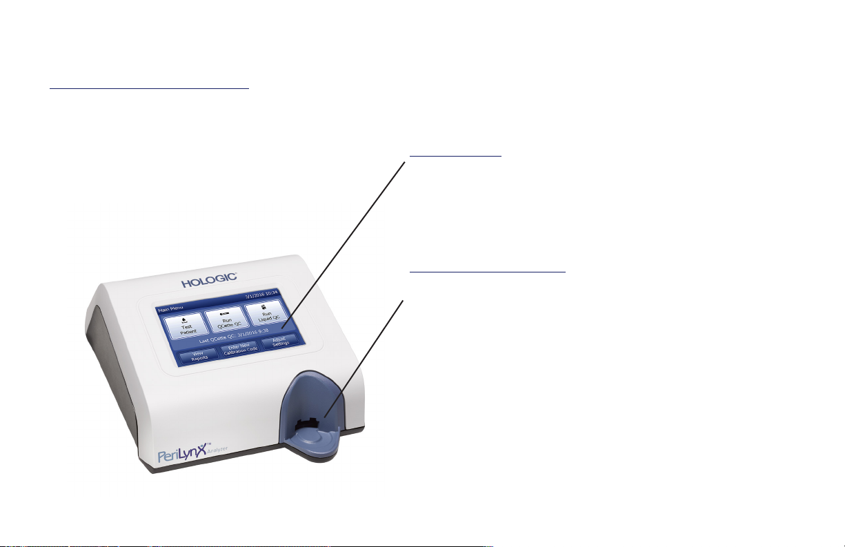
Components of the Analyzer
The major components of the analyzer are the touch screen and the cassette insertion site.
Touch screen
Use the touch screen to enter data, select options, and
move through the menus.
See Section 3 — General Operating/Testing Instructions,
for a full description of using the touch screen.
Cassette insertion site
The Cassette Insertion Site contains a slightly concave
trough designed to capture any fluids that may have been
spilled while applying sample to the cassette. This area of
the instrument should be cleaned regularly (see Section
5 — Care of the Analyzer).
Note: For the detection of fetal fibronectin (fFN)
in cervicovaginal secretions, insert a
RapidfFN10Q Cassette or PeriLynx QCette
only.
PeriLynx™ System User Manual
Section 1 — Introduction
1-2
Page 10
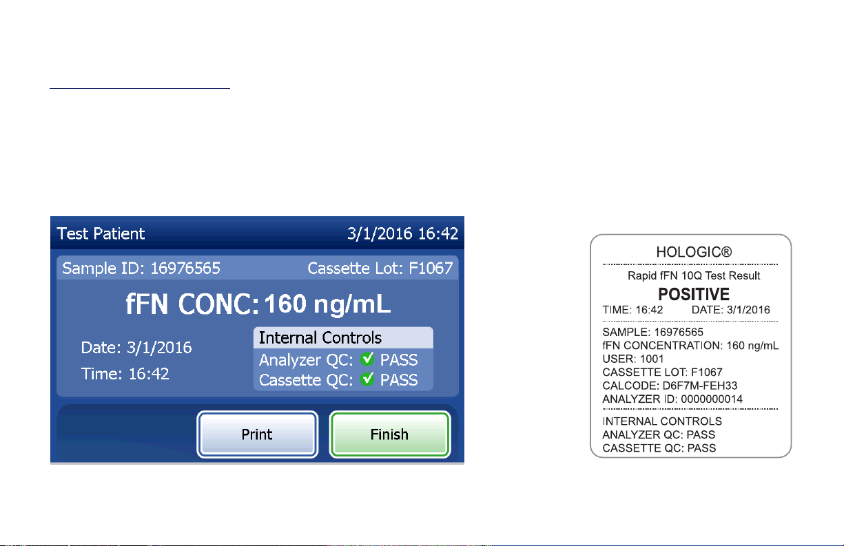
Displayed/Printed Results
Each menu function result is displayed on the analyzer touch screen. With Auto Print ON, the result is
automatically printed. Each printed result requires one printer label. Results can be printed from any data record
screen either immediately after a test or in Access Data mode. The example below demonstrates the display and
printout of a patient test.
Example: Displayed/Printed Results of Patient Test
Displayed Printed
PeriLynx™ System User Manual
Section 1 — Introduction
1-3
Page 11
Specifications
Power Supply UL +24 VDC listed power supply
Memory Capacity 50 Calibration Records
50 QCette Records
50 Control Records
1000 Patient Records
Touch screen 5-inch diagonal display with 480 x 800 resolution and
256 colors. Resistive interface.
Dimensions Length — 10 inches (25.4 cm)
Width — 7.5 inches (19.05 cm)
Height — 4 inches (10.16 cm)
Weight — 2.4 pounds (1090 g)
Operating Temperature 15° to 30°C
59° to 86°F
Operating Humidity 20% to 80%, non-condensing
PeriLynx™ System User Manual
Section 1 — Introduction
1-4
Page 12

Sound level, analyzer Maximum A-weighted sound pressure level at the typ-
ical user’s position and at a radius of 1 meter around
the analyzer is 56 dB.
A.C. Supply 100-240VAC
50-60 Hz
2.1A
Input Connector Coaxial power plug with positive center conductor
Output Connectors 9-pin RS-232 connector
3 host USB connectors
Ethernet connector
Printer power connector
PeriLynx™ System User Manual
Section 1 — Introduction
1-5
Page 13

Cautions and Warnings
There are no known hazards associated with the PeriLynx system when it is operated in accordance with the
instructions in this manual. However, you should be aware of situations that can result in serious injury.
WARNING! Ensure that the analyzer power adapter is connected to an AC electrical outlet that provides
voltage and current specified by Hologic. Use of an incompatible power receptacle can cause shock
and fire hazard.
CAUTION! Use only the power adapter supplied by Hologic. Use of an incompatible power adapter can
damage the internal components.
CAUTION! Always turn off the power and unplug the power adapter before cleaning the exterior of the
analyzer. Fluid can damage internal components. DO NOT clean the power adapter.
CAUTION! Extreme heat can damage the display and other electronic components.
PeriLynx™ System User Manual
Section 1 — Introduction
1-6
Page 14

WARNING! Never apply cleaning reagents by spray as the liquid may leak into the analyzer causing
damage to the electrical components or possibly electrical shock to the user.
CAUTION! Do not immerse the analyzer in liquid. Fluid can damage internal components.
CAUTION! Do not clean the touch screen display with undiluted bleach solution or other solvents. Caustic
cleaning solutions can damage the touch screen.
CAUTION! Use appropriate laboratory procedures for handling biohazardous materials.
If this equipment is used in a manner not specified by the manufacturer, then the protection provided by the
equipment may be impaired.
FCC Notice:
This equipment has been tested and found to comply with the limits for a Class A digital device, pursuant to part
15 of the FCC Rules. These limits are designed to provide reasonable protection against harmful interference
when the equipment is operated in a commercial environment. This equipment generates, uses, and can radiate
radio frequency energy and, if not installed and used in accordance with the instruction manual, may cause
harmful interference to radio communications. Operation of this equipment in a residential area is likely to cause
harmful interference in which case the user will be required to correct the interference at his own expense.
PeriLynx™ System User Manual
Section 1 — Introduction
1-7
Page 15

FCC Warning:
Changes or modification not expressly approved by the manufacturer responsible for compliance could void the
user’s authority to operate the equipment.
Note: The use of a non-shielded interface cable with this equipment is prohibited.
CE Notice:
This equipment has been tested and found to be in compliance with the following standards per the IVD
Directive:
EN61326-2-6 Electrical Equipment for Measurement, Control and Laboratory Use; EMC Requirements;
In Vitro Diagnostic (IVD) Medical Equipment.
EN61010-2-101 Electrical Equipment for Measurement, Control and Laboratory Use; Part 101; Particular
requirements for In Vitro Diagnostic (IVD) Medical Equipment. This equipment has been
designed and tested to CISPR 11 Class A. In a domestic environment it may cause radio
interference, in which case, you may need to take measures to mitigate the interference.
The electromagnetic environment should be evaluated prior to operation of the device.
Do not use this device in close proximity to sources of strong electromagnetic radiation
(e.g. unshielded intentional RF sources), as these may interfere with the proper operation.
PeriLynx™ System User Manual
Section 1 — Introduction
1-8
Page 16

This equipment also complies with the following safety standards:
UL61010-1 Safety Requirements for Electrical Equipment for Laboratory Use Part 1: General
Requirements, with an ETL or equivalent Approval Mark
ICES-003 Industry Canada Regulation: Interference-Causing Equipment Standards - Digital
Apparatus
CAN/CSA C22.2 No. 61010-2-101
Safety Requirements for Electrical Equipment for Measurement, Control and Laboratory
Use - Part 1: General Requirements, with ETL or equivalent Approval Mark
PeriLynx™ System User Manual
Section 1 — Introduction
1-9
Page 17

Disposal of Electrical & Electronic Equipment
Waste Electrical and Electronic Equipment (WEEE)
Hologic is dedicated to meeting country specific requirements associated with the environmentally sound
treatment of our products. Our objective is to reduce the waste arising from our electrical and electronic
equipment. Hologic realizes the benefits of subjecting such WEEE equipment to potential reuse, treatment,
recycling or recovery to minimize the amount of hazardous substances entering the environment.
Your responsibility
As a Hologic customer, you are responsible for ensuring that devices marked with the symbol shown below are
not placed into the municipal waste system unless authorized to do so by the authorities in your area. Please
contact Hologic (see below) prior to disposing any electrical equipment provided by Hologic.
Symbol used on the instrument
The following symbol is used on this instrument:
Do not dispose in municipal waste.
Contact Hologic (see below) for information
regarding proper disposal.
Reclamation
Hologic will provide for the collection and proper reclamation of electrical devices we provide to our customers.
Hologic strives to reuse Hologic devices, subassemblies, and components whenever possible. When reuse is
not appropriate, Hologic will ensure the waste material is properly disposed of.
PeriLynx™ System User Manual
Section 1 — Introduction
1-10
Page 18

Hologic Contact Information
Corporate Headquarters Hologic, Inc.
250 Campus Drive
Marlborough, MA 01752 USA
Tel: (USA and Canada)
1-888-PRETERM (1-888-773-8376)
1-800-442-9892
1-508-263-2900
Fax: 1-508-263-2967
Authorized Representative in the
European Community
PeriLynx™ System User Manual
Section 1 — Introduction
Hologic Ltd.
Heron House, Oaks Business Park
Crewe Road, Wythenshawe
Manchester, M23 9HZ, UK
Tel: +44 (0)161 946 2206
1-11
Page 19

Symbols Used on the Instrument
30˚C
15˚
The following symbols may appear on this instrument or its packaging:
Caution, consult instructions for
use
Waste Electrical and Electronic
Equipment - contact Hologic for
disposal of the instrument.
Catalogue Number
Serial Number Biological risks
For in vitro diagnostic testing Direct current (DC)
PeriLynx™ System User Manual
Section 1 — Introduction
Manufacturer
Authorized Representative in
the European Community
Store between 15°C and
C
30°C
1-12
Page 20

Section 2 — Installation
General
This section provides detailed installation instructions for the PeriLynxsystem. Follow installation steps carefully
to insure proper installation and operation.
Environmental Factors
The PeriLynxsystem has been designed to be safe under the following conditions:
• Indoor use;
• Altitudes up to 2000 m;
• Maximum relative humidity of 80% for temperatures up to 30°C;
• Pollution Degree II, in accordance with IEC 61010-1 Category II. The PeriLynx system is for use only in an
ofce or a clean laboratory environment.
• The operating temperature should be held relatively constant. The optimum operating temperature is 15° to
30°C (59° to 86°F). Before operating, allow the instrument to equilibrate to room temperature.
Place the instrument away from direct sunlight and away from locations subject to extreme temperature
variations (e.g., near open windows, ovens, hot plates, radiators, etc.).
PeriLynx™ System User Manual
Section 2 — Installation
2-1
Page 21
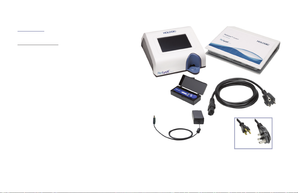
Unpacking
PeriLynxanalyzer
Carefully remove the analyzer and
accessories from the shipping carton.
Inspect the carton and the analyzer for visible
signs of damage. If the analyzer is damaged,
immediately contact the carrier and Hologic
Customer Service.
The carton should contain the following
parts/accessories:
• PeriLynx analyzer
• AC adapter and power cord (one or more for
international compatibility)
• User manual
• PeriLynx QCette
®
Note: Retain the shipping carton for future use. If the analyzer needs to be
shipped, use the original shipping carton.
PeriLynx™ System User Manual
Section 2 — Installation
2-2
Page 22

Printer
Carefully remove the printer and accessories from the
shipping carton. Inspect the carton and the printer for
visible signs of damage. If the printer is
damaged, immediately contact the carrier
and Hologic Customer Service.
The printer carton should contain the
following parts/accessories:
• Printer
• Printer labels (1 roll)
• Power cord
• USB cable
Note: Retain the shipping carton for future use. If the
printer needs to be shipped, use the original
shipping carton.
PeriLynx™ System User Manual
Section 2 — Installation
2-3
Page 23

Barcode scanner (optional)
A barcode scanner is available from Hologic for entering data into the analyzer.
This barcode scanner is the only barcode scanner for use with the PeriLynx
system. If your order included the optional barcode scanner, carefully remove
the barcode scanner and accessories from the shipping carton. Inspect the
carton and the barcode scanner for visible signs of damage. If the barcode
scanner is damaged, immediately contact the carrier and Hologic Customer
Service.
Follow all of the instructions provided by the barcode scanner manufacturer
regarding the safe use of the barcode scanner.
The barcode scanner carton should contain the following parts/accessories:
• Barcode scanner
• Stand
PeriLynx™ System User Manual
Section 2 — Installation
2-4
Page 24
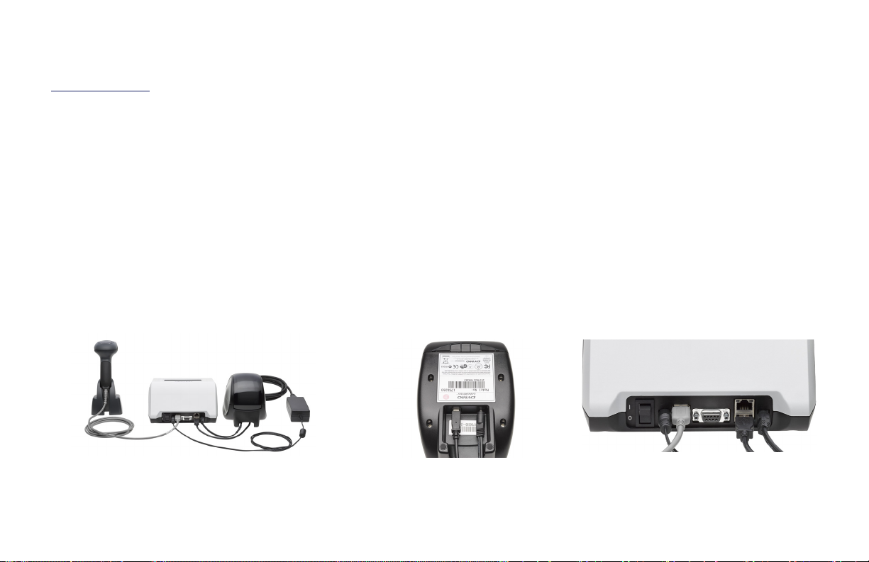
System Setup
1. The analyzer and printer should be placed on a flat, level surface. Verify that the power switch on the back
of the analyzer is set to the off (0) position.
Note: Do not install any of the Dymo Label software that comes with the printer.
2. Plug the power cable jack into the receptacle labeled 24V DC on the bottom of the printer. Plug the other
end of the cable into the PeriLynxanalyzer.
3. Insert the USB cable into the receptacle labeled USB on the bottom of the printer. Route the USB cable
and the power cable through the cable channel and set the printer upright on a flat surface. Plug the other
end of the USB cable into any of the USB ports on the analyzer.
System
(Photo includes optional barcode scanner)
PeriLynx™ System User Manual
Section 2 — Installation
Printer
Analyzer
2-5
Page 25

4. Use the AC cord corresponding to the room power outlets. Plug the output jack from the power adapter
into the rear of the analyzer. Plug the wall mount adapter into an AC power outlet.
Caution: Only the power adapter provided with the PeriLynxanalyzer may be used. Any substitutions can
result in damage to the PeriLynxanalyzer and printer.
5. To connect the optional barcode scanner, plug the USB cable of the scanner into any of the USB ports on
the analyzer.
PeriLynx™ System User Manual
Section 2 — Installation
2-6
Page 26
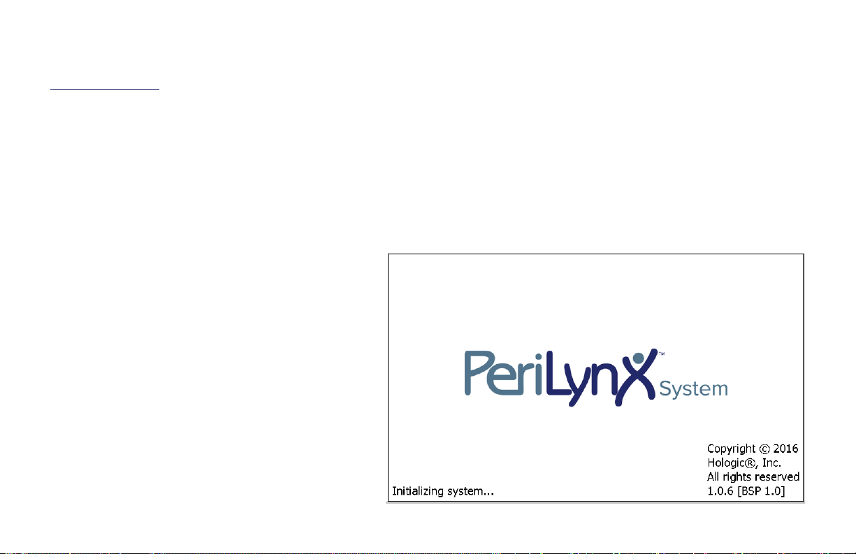
Getting Started
Turn the analyzer power switch to the on ( l ) position. The power switch is located on the back of the
instrument. (If the analyzer does not turn on, see Section 7 — Troubleshooting, Item 1.)
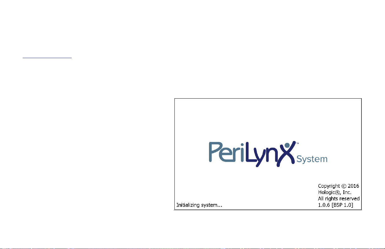
Upon power up, the analyzer displays the Hologic logo and then PeriLynxsystem logo with the message
“Initializing system...” for 60 seconds. Then, the analyzer performs a self-test of the analyzer components.
If there is a problem after the self-test, a
beep will sound to indicate an error and
an error message will be displayed. If an
error message is displayed, refer to the
troubleshooting section of the manual.
If the printer is not connected, an error
message will be displayed.
PeriLynx™ System User Manual
Section 2 — Installation
2-7
Page 27
Once the self-test is complete, the display will change to the Main Menu. The date and time may need to be
reset for your time zone.
PeriLynx™ System User Manual
Section 2 — Installation
2-8
Page 28
Setting the Date and Time
1. From the Main Menu, select Adjust Settings.
2. Touch Date/Time Settings and follow the prompts.
For more details about setting the date and time, see Section 4 — Software Functions — Detailed Descriptions.
PeriLynx™ System User Manual
Section 2 — Installation
2-9
Page 29

Factory Default Settings
The PeriLynxsystem uses the following default settings. To customize the unit to your laboratory requirements,
refer to Section 4 — Software Functions — Detailed Descriptions.
The default settings are as follows:
Auto Print
Factory setting is
Auto Print
ON. After every result, the printer will generate a printed result.
Date format
The default setting is MM/DD/YY.
Time format
The default setting is 24 hour time.
Sound settings
The default setting is for the audible tone (beep) to be turned on at a volume of 5.
Password settings
The default setting has the password disabled.
PeriLynx™ System User Manual
Section 2 — Installation
2-10
Page 30

Shutdown
The system may be left plugged in and idle when not in use. If the system is to be shut down make sure it is idle.
Move the power switch on the back of the analyzer to the off position.
Extended Shutdown
If the system is to be turned off for a long period of time, or taken out of use, power off the analyzer as
described above. Completely remove power from the device by unplugging the power cord from the electrical
outlet.
PeriLynx™ System User Manual
Section 2 — Installation
2-11
Page 31

Section 3 — General Operating/Testing Instructions
After instrument installation, the PeriLynxanalyzer can be operated on a day-to-day basis by using the following
procedures. Read Section 4 for detailed descriptions of displays, prompts and operating sequences.
Starting the System
1. Turn the analyzer power switch to the on position. The power switch is located on the back of the
instrument. (If the analyzer does not turn on, see Section 7, Troubleshooting, Item 1.)
Upon power up, the analyzer displays the message “Initializing system...” for 60 seconds. Then, the analyzer will
perform a self-test of the analyzer components.
If there is a problem after the self-test, a beep will sound to indicate an error and an error code will be displayed.
If an error code is displayed, refer to the troubleshooting section of the manual. Verify the date and time are
correct. See Section 4 — Software Functions — Detailed Descriptions, for setting Date/Time.
2. Once it is connected to the analyzer, the printer is continuously powered on. Ensure labels are in the
printer. See Section 6 — Printer, for loading printer labels.
PeriLynx™ System User Manual
Section 3 — General Operating/Testing Instructions
3-1
Page 32

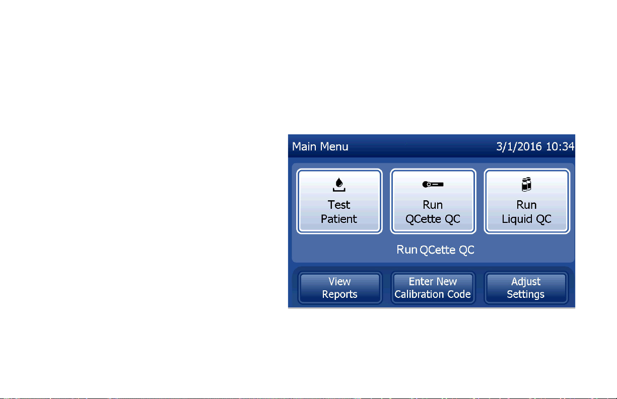
Overview of PeriLynx Analyzer Main Menu
Main Menu Purpose
Test Patient Runs the Rapid fFN 10Q test on a patient sample.
Run QCette QC Compares functional parameters of the QCette against those of its original
setup. Ensures the analyzer is functioning properly. Performed daily.
Run Liquid QC Runs the liquid control samples on the analyzer to ensure the
PeriLynxSystem functions properly. Performed at installation and with every
cassette lot change or shipment.
View Reports View/print the results of patient tests, QCette and control checks and system
calibration results. Allows for transfer of data via the data port.
Enter New Calibration Code Allows the calibration code for a lot of cassettes to be entered and stored
into analyzer memory. Performed at installation and with every cassette lot
change.
Adjust Settings Allows change to date/time, sound,
Auto Print,
and password settings. Allows
QCette setup.
Update Software Allows the software version to be updated.
The main menu also displays the status of the QCette QC.
PeriLynx™ System User Manual
Section 3 — General Operating/Testing Instructions
3-2
Page 33
Typical Menu Item Sequences
Upon System Installation Routine Daily Use New Lot of Cassettes
Date /Time Settings Run QCette QC Enter New Calibration Code
Select Auto Print On/Off Test Patient Run QCette QC
QCette Setup View Reports Run Liquid QC
Enter New Calibration Code Test Patient
Run QCette QC View Reports
Run Liquid QC
Test Patient
View Reports
PeriLynx™ System User Manual
Section 3 — General Operating/Testing Instructions
3-3
Page 34

Using the Touch Screen
On the touch screen, touching a button name selects it.
For ID fields that require data entry, touch a letter or number key to enter it. The alphabet is always uppercase.
To switch from the alphabet keys to the number keys, touch the “123” button near the top of the screen. To
switch from the number keys to the alphabet keys, touch the “ABC” button. Use the Delete key to delete one
character. Use the Space key to enter a space in the position of the cursor.
To clear the entire ID field, touch the “x” to the
right of the ID field area.
The optional barcode scanner can also be used
to enter data into fields.
To see an entry that is longer than the ID field
area or to edit an entry, touch the ID field area.
To edit an entry, use the alphabet, number, or
Delete keys.
PeriLynx™ System User Manual
Section 3 — General Operating/Testing Instructions
3-4
Page 35
Help button
The Help button provides information about the data entry. Press Close to exit the Help and enter the correct
data.
Next button
Follow the prompts on the analyzer. Typically, the Next button confirms an entry in a data entry field and
advances to the next part of the sequence. The Next button is green only when the analyzer is ready to move to
the next part of the sequence.
Back button
Touch Back to return to the previous screen,
unless otherwise specified.
PeriLynx™ System User Manual
Section 3 — General Operating/Testing Instructions
3-5
Page 36

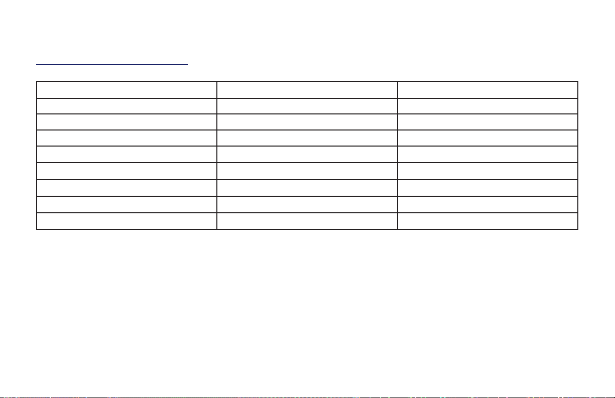
Field Length Required Format
User Up to 15 characters Any combination of letters and numbers. An entry
must be made.
Sample ID Up to 16 characters Any combination of letters and numbers. An entry
must be made.
Cassette Lot Number 5 characters ANNNN where A=Alpha, N=Number. Enter the lot
number exactly as it appears on the cassette pouch.
The alphabet is limited on this screen to letters used
in cassette lot numbers. An entry must be made.
Calibration Code 10 characters Enter the cal code exactly as it appears on the
cassette box.
Liquid Control Lot Number Up to 12 characters Enter the liquid control lot number exactly as it
appears on the bottle, or scan the lot number
barcodes on the control kit box. An entry must be
made.
QCette ID 6 characters Enter the QCette serial number exactly as it appears
on the QCette. An entry must be made.
The analyzer displays an error and beeps if the wrong format is entered or if an invalid code is entered. Press
Close to dismiss the error and enter the correct data.
PeriLynx™ System User Manual
Section 3 — General Operating/Testing Instructions
3-6
Page 37

Scrolling through data records
Use the up or down arrow when scrolling through data records in longer reports, such as Monthly Usage.
Print
Press Print to print a data record.
This print function is only active when a data record is on the display screen.
Cancel button
A Cancel button is available in some cases to stop a sequence and return to the previous screen.
Main Menu
Touch the Main Menu button to return to the
Main Menu.
PeriLynx™ System User Manual
Section 3 — General Operating/Testing Instructions
3-7
Page 38

Run QCette QC — Quick Reference
Run QCette QC should be performed at least once every 24 hours. Note that the Main Menu displays the date
and time of the last performance of this check.
From the Main Menu select
Run QCette QC. Enter User ID and press Next.
Enter the QCette ID, or verify, if it is already
entered. Press Next. Insert QCette and press Next.
If the QCette does not pass, see Section 7 — Troubleshooting, Item 9.
PeriLynx™ System User Manual
Section 3 — General Operating/Testing Instructions
Results will be displayed and printed in
3minutes.
3-8
Page 39

Test Patient — Quick Reference
Be sure to prepare the specimen sample according to your specific protocols.
Enter the cassette lot number (on cassette
From the Main Menu select Test Patient. Enter User ID and press Next.
Remove the patient cassette from its
pouch.
Enter the patient accession number and
press Next.
Insert the cassette into the analyzer and
press Next.
pouch) and press Next.
The analyzer will check that a
RapidfFN10Q Cassette is properly
inserted.
PeriLynx™ System User Manual
Section 3 — General Operating/Testing Instructions
3-9
Page 40
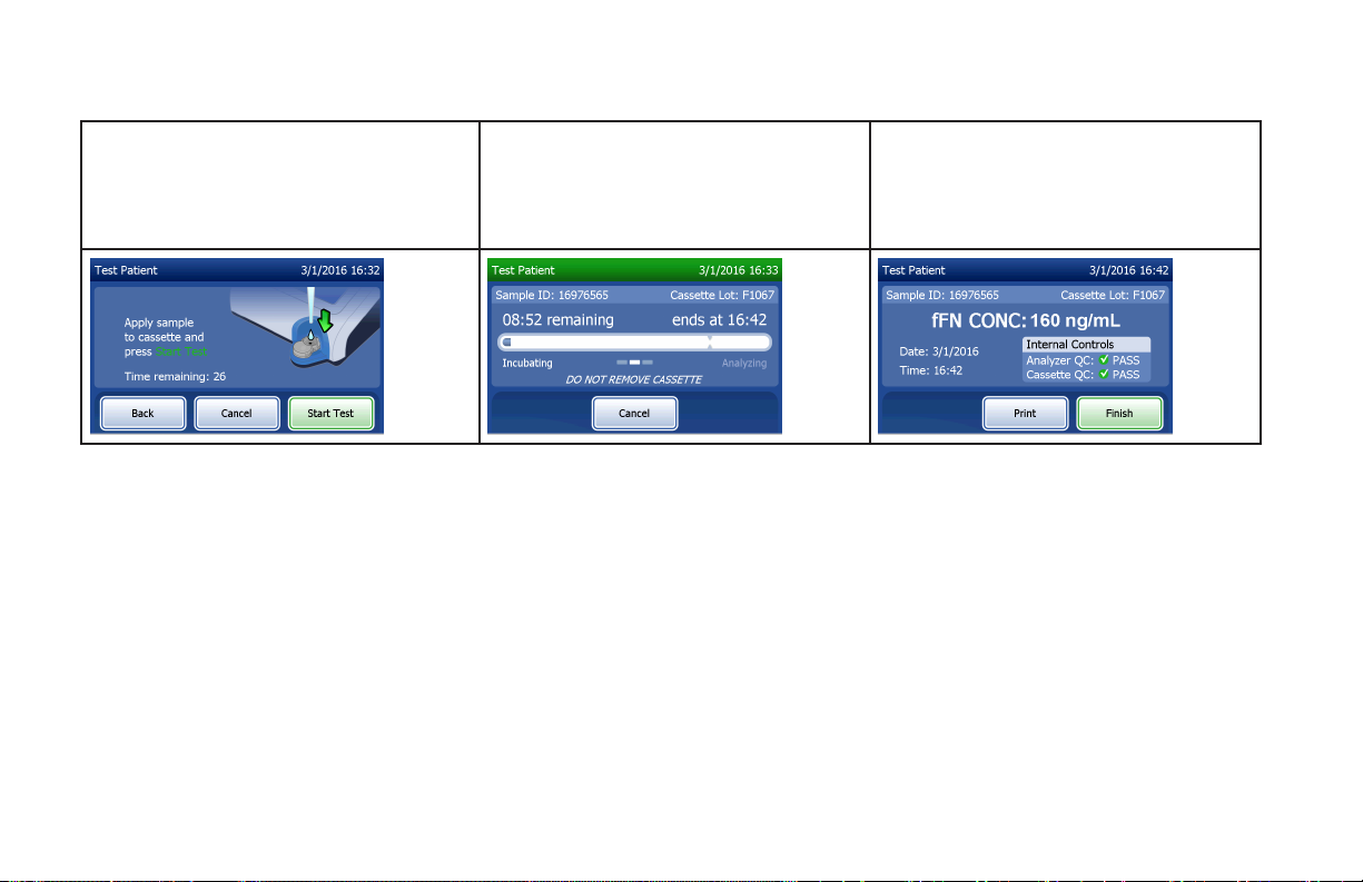
The instrument will beep repeatedly and
the display will read, “Apply sample to
cassette and press Start Test.”
Add 200 µL of patient sample and press
Start Test.
The analyzer will begin a 10-minute
countdown, with 7 minutes of incubation
and 2–3 minutes of analysis of the
cassette.
When testing is complete, the system will
display and print the result.
PeriLynx™ System User Manual
Section 3 — General Operating/Testing Instructions
3-10
Page 41

Enter New Calibration Code — Quick Reference
Calibration must be set when changing cassette lots.
From the Main Menu, select Enter New
Calibration Code. Enter User ID and press Next.
Calibration results will be displayed and
Enter the Calibration Code (on the cassette
box) and press Next.
can be printed.
Press Finish to return to the Main Menu.
Enter the cassette lot number (on cassette
pouch) and press Next.
PeriLynx™ System User Manual
Section 3 — General Operating/Testing Instructions
3-11
Page 42

Run Liquid QC — Quick Reference
Run Liquid Controls with every cassette lot change.
From the Main Menu, select Run Liquid
QC. Enter the User ID and press Next.
Select Level 1 or Level 2 and press Next. Enter the Control Lot number (on bottle
label and controls’ box) and press Next. Insert cassette and press Next.
PeriLynx™ System User Manual
Section 3 — General Operating/Testing Instructions
Enter the Cassette Lot number (on
cassette pouch) and press Next.
3-12
Page 43

The instrument will beep repeatedly and
The analyzer will check that a
RapidfFN10Q cassette is properly
inserted.
When testing is complete, the system will
display and print the result. Select Finish
to run the next control sample.
the display will read, “Add sample to
cassette and press Start Test.”
Add 200 µL of control sample and press
Start Test.
Note: Both a Level 1 and a Level 2 control
sample must be run.
The analyzer will begin a 10-minute
countdown, with 7 minutes of incubation
and 2–3 minutes of analysis of the
cassette.
Repeat the test with the other control
sample and a fresh cassette.
If the liquid control result does not pass, refer to Section 7 — Troubleshooting, Item 10.
PeriLynx™ System User Manual
Section 3 — General Operating/Testing Instructions
3-13
Page 44
Section 4 — Software Functions — Detailed Descriptions
Startup Screen
Upon power up, the analyzer displays the Hologic logo and then PeriLynxsystem logo with the message
“Initializing system...” for 60seconds. Then the analyzer performs a self-test of the analyzer components. This
screen also displays the software version.
Once the self-test is complete, the display will
change to the Main Menu.
PeriLynx™ System User Manual
Section 4 — Software Functions — Startup Screen
4-1
Page 45
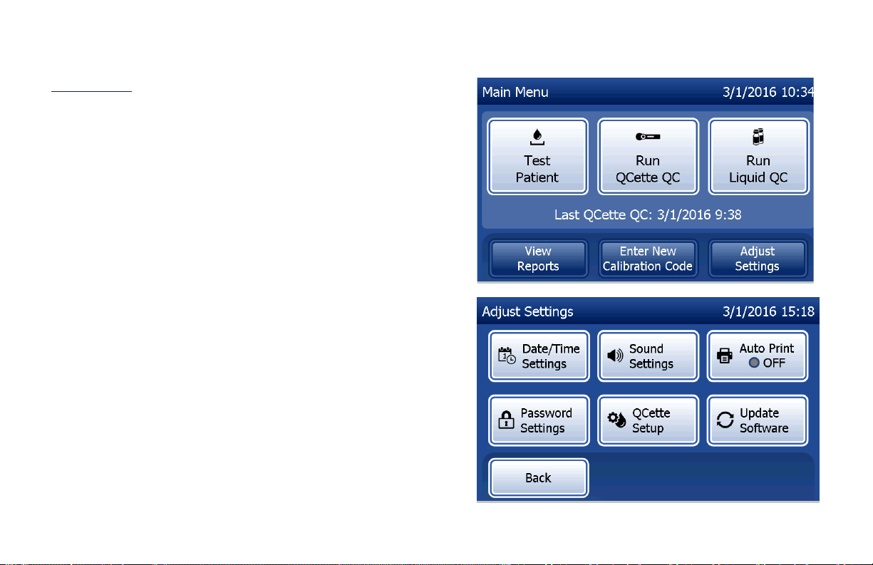
Main Menu
The Main Menu consists of Test Patient, Run QCette QC,
Run Liquid QC, View Reports, Enter New Calibration Code,
and Adjust Settings.
For View Reports and Adjust Settings, selecting the button
displays a submenu.
PeriLynx™ System User Manual
Section 4 — Software Functions — Main Menu
4-2
Page 46
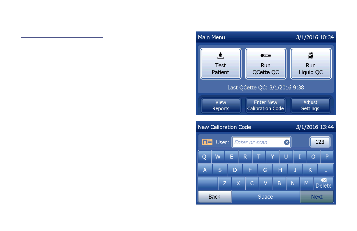
Enter New Calibration Code
Select Enter New Calibration Code on the Main Menu
screen to set the calibration on the analyzer. Follow the
analyzer prompts. Calibration must be set when changing
cassette lots.
Note: If the calibration has not been set, Test Patient
and Run Liquid QC cannot be run. Calibration
must be set before the analyzer can be used for
testing.
The User ID must be entered to proceed to the next
step. Press Next to accept the ID. This field will accept
15alphanumeric characters.
PeriLynx™ System User Manual
Section 4 — Software Functions — Enter New Calibration Code
4-3
Page 47
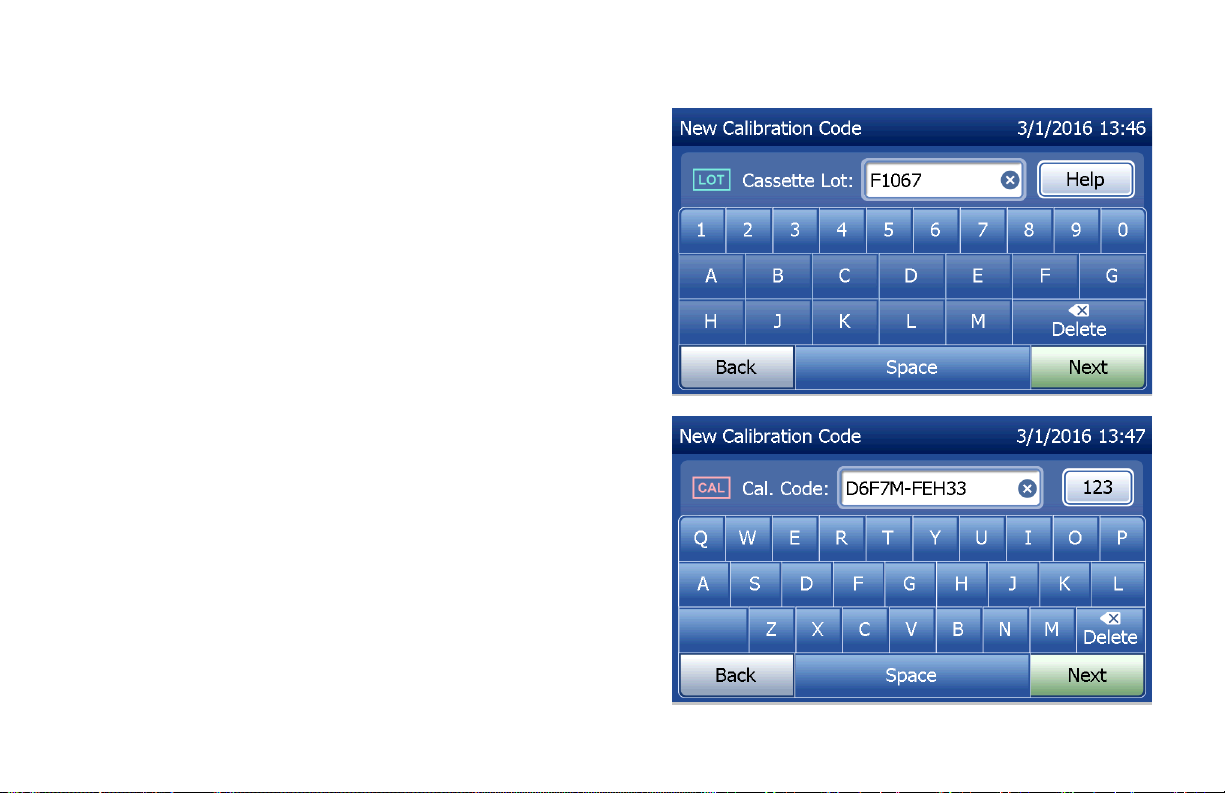
The Cassette Lot number must be entered to proceed to
the next step. The Cassette Lot is located on the cassette
pouch and the cassette box. The software requires that
the lot number is entered in the correct format: one alpha
character followed by four numeric characters (e.g., F1067).
The Calibration Code (Cal. Code) must be entered to
proceed to the next step. The calibration code is located
on the cassette box. The software requires that the code
number is entered in the correct format: 10alphanumeric
characters with a dash in the middle. Enter the calibration
code exactly as it is given on the box.
Note: The calibration code is established by Hologic for
each lot of RapidfFN10Q Cassettes.
PeriLynx™ System User Manual
Section 4 — Software Functions — Enter New Calibration Code
4-4
Page 48

Calibration data record
The complete record will be printed automatically if
Auto Print
is set to ON, or it may be printed/reprinted by
pressing the Print button.
Display and Printout
PeriLynx™ System User Manual
Section 4 — Software Functions — Enter New Calibration Code
4-5
Page 49

Test Patient
Select Test Patient on the Main Menu to test a patient
sample. Follow the analyzer prompts.
The User ID must be entered to proceed to the next
step. Press Next to accept the ID. This field will accept
15alphanumeric characters.
PeriLynx™ System User Manual
Section 4 — Software Functions — Test Patient
4-6
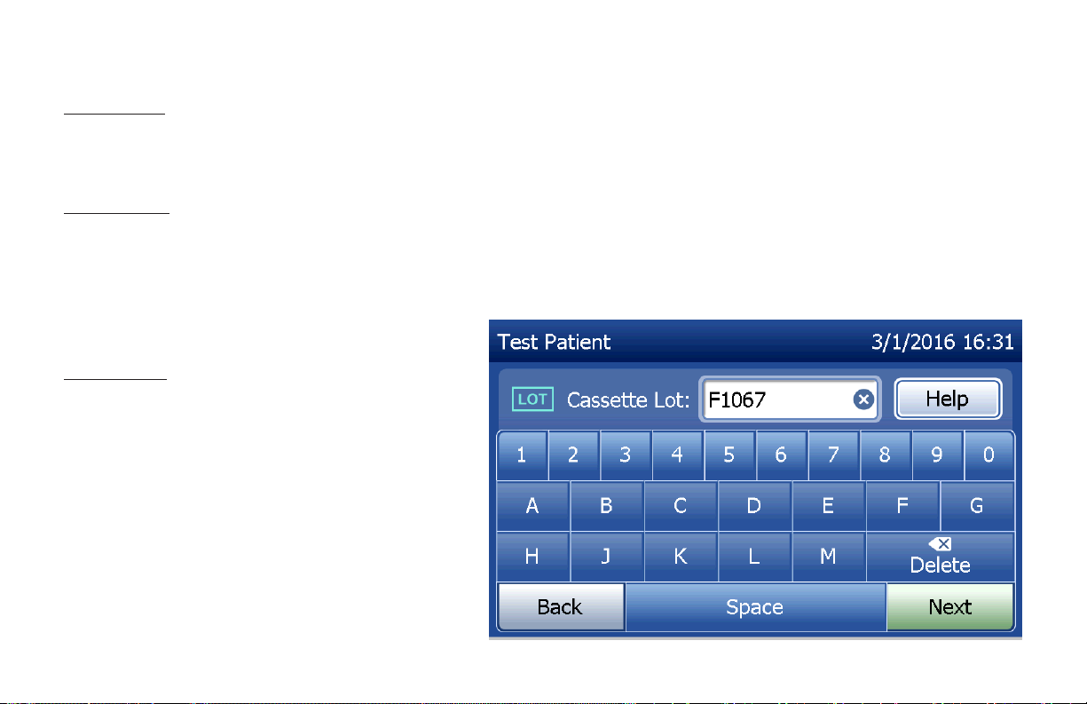
Page 50

The Cassette Lot number must be entered to proceed to
the next step. The Cassette Lot is located on the cassette
pouch and the cassette box. The software requires that
the lot number is entered in the correct format: one alpha
character followed by four numeric characters (e.g., F1067).
It is important to use the cassette lot number on each
cassette’s pouch or box.
The analyzer automatically compares the cassette lot
number used to set calibration with the cassette lot number
used for patient testing. The analyzer accepts cassettes
from any of the last five cassette lots for which calibration
has been set.
If the cassette lot numbers do not match, the test
process cannot continue. When this occurs, the display
says that the cassette lot has not been calibrated. Press
Close and the cassette lot number used for calibration
will be displayed.
Note: If the cassette lot number has changed, Enter
New Calibration Code must be performed.
PeriLynx™ System User Manual
Section 4 — Software Functions — Test Patient
4-7
Page 51

Enter up to 16alphanumeric characters for a Sample
ID and press Next. The Sample ID must be entered to
proceed to the next step.
This message will be displayed if a cassette is present
in the analyzer prior to reaching the next screen.
Remove cassette and press Next.
PeriLynx™ System User Manual
Section 4 — Software Functions — Test Patient
4-8
Page 52
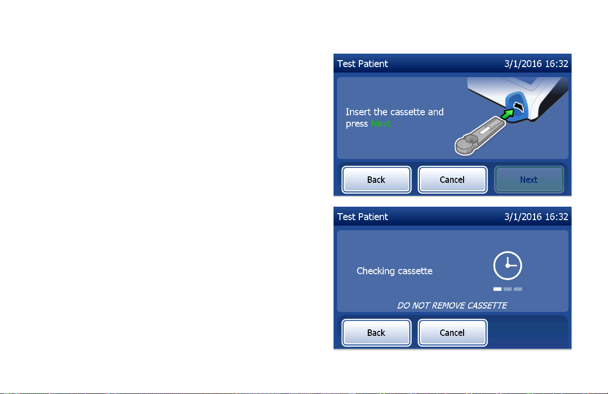
The analyzer then prompts the user to insert cassette and
press Next.
The analyzer will check that a RapidfFN10Q cassette is
properly inserted.
PeriLynx™ System User Manual
Section 4 — Software Functions — Test Patient
4-9
Page 53

If the wrong kind of cassette is inserted, the test
cannot proceed. Press Close and remove the incorrect
cassette.
A 30-second timer starts during which time the analyzer
beeps. Add 200µL of patient sample and immediately
press Start Test.
PeriLynx™ System User Manual
Section 4 — Software Functions — Test Patient
4-10
Page 54
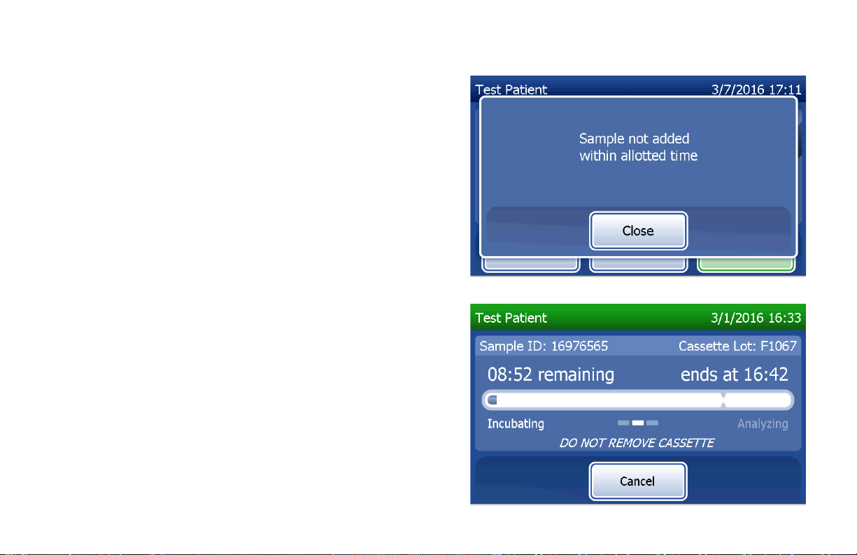
If the patient sample is not added and Start Test is not
pressed within allotted time, the test process cannot
continue. The display says that the sample was not
added in time. Press Close, remove the cassette, and
press Finish to return to the Main Menu. No record of
the test will be held in memory.
Once the sample is added, the analyzer will begin a
10-minute countdown.
To abort the test, press Cancel. Pressing Cancel and
then confirming that you want to stop the process will
terminate the test and the data will be lost.
Upon completion of the 7-minute incubation period, the
analyzer will begin the analysis of the cassette. Do not
disturb the analyzer until the results are displayed. The
analysis will take approximately 2–3 minutes.
PeriLynx™ System User Manual
Section 4 — Software Functions — Test Patient
4-11
Page 55

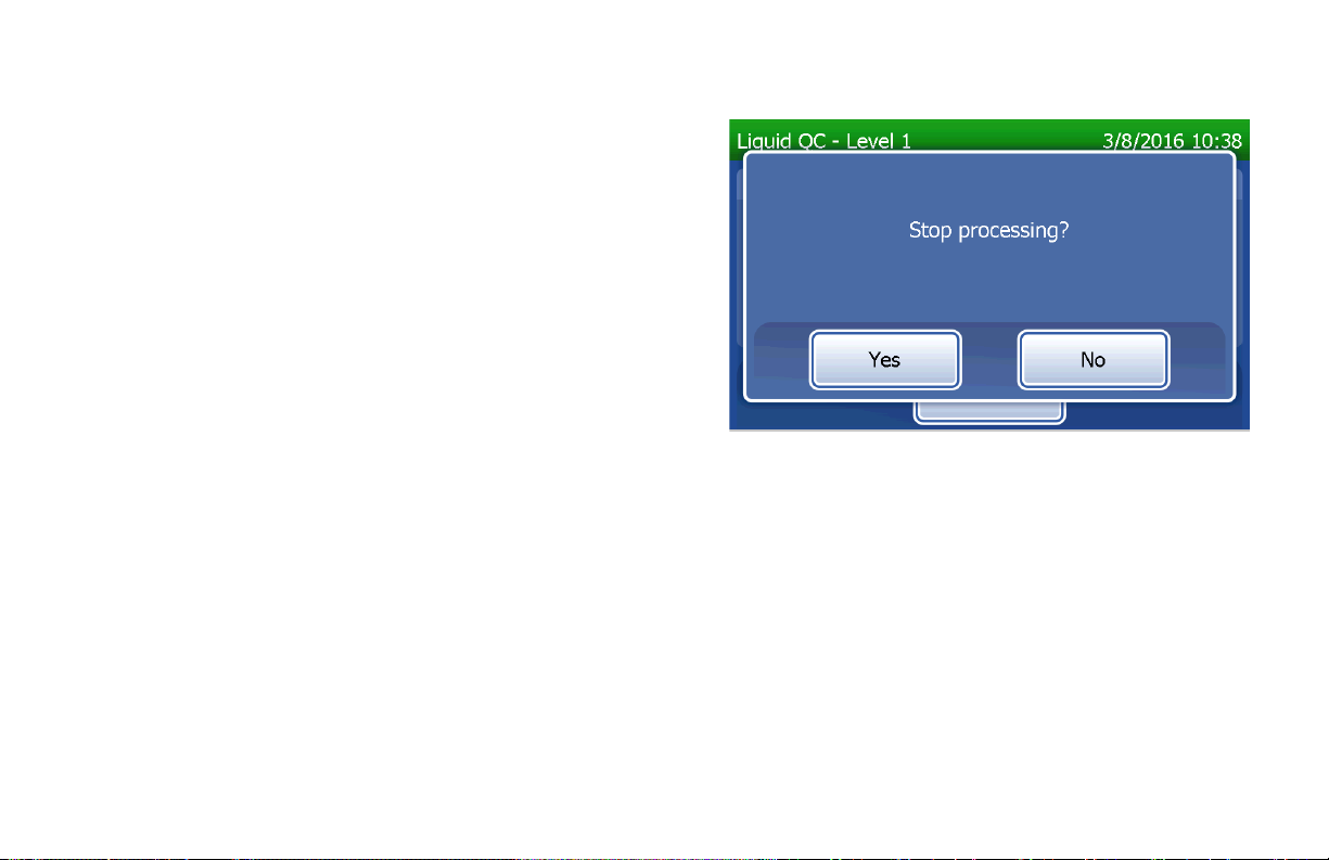
This message will be displayed if Cancel was pressed
during testing. Select Yes to stop processing or No to
continue the test. This message will hold for 5seconds
and then continues the test. If the test is cancelled,
remove the cassette and press Finish. A new cassette
will be required to repeat the test.
PeriLynx™ System User Manual
Section 4 — Software Functions — Test Patient
4-12
Page 56
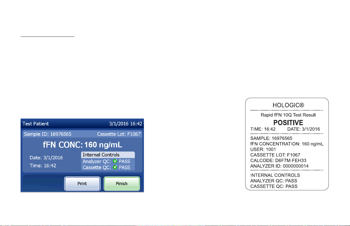
Patient data record
The patient test results are displayed. The complete record will be printed automatically if
ON, or it may be printed/reprinted by pressing the Print button.
Display and Printout
Patient results are displayed as the fFN concentration in ng/mL, or INVALID.
Auto Print
is set to
PeriLynx™ System User Manual
Section 4 — Software Functions — Test Patient
4-13
Page 57

An INVALID result should be repeated. (See Section 7 — Troubleshooting, Item 12.)
Note: Internal Controls are performed automatically during each Rapid fFN test. These internal controls
check for
(1) a threshold level of signal at the procedural control line,
(2) proper sample flow across the RapidfFN10Q cassette,
(3) absence of conjugate aggregation, and
(4) proper functioning of the PeriLynx analyzer hardware.
PeriLynx™ System User Manual
Section 4 — Software Functions — Test Patient
4-14
Page 58

Run QCette QC
Prior to running the PeriLynxQCette® for the first time,
QCette Setup must be performed. See Adjust Settings —
QCette Setup. Refer to the PeriLynxQCette directional
insert for more information.
Run QCette QC should be performed at least once every
24hours. Note that Main Menu shows the date and time of
the Last QCette QC.
From the Main Menu, select Run QCette QC.
The User ID must be entered to proceed to the next
step. Press Next to accept the ID. This field will accept
15alphanumeric characters.
PeriLynx™ System User Manual
Section 4 — Software Functions — Run QCette QC
4-15
Page 59

The QCette ID is displayed. (It was originally entered during
QCette setup.) The QCette ID is the serial number for the
QCette. Confirm that the serial number displayed matches
the serial number printed on the QCette plastic housing and
press Next. The software requires that the serial number is
entered in the correct format: six numeric characters (e.g.,
014899). Enter all leading zeros.
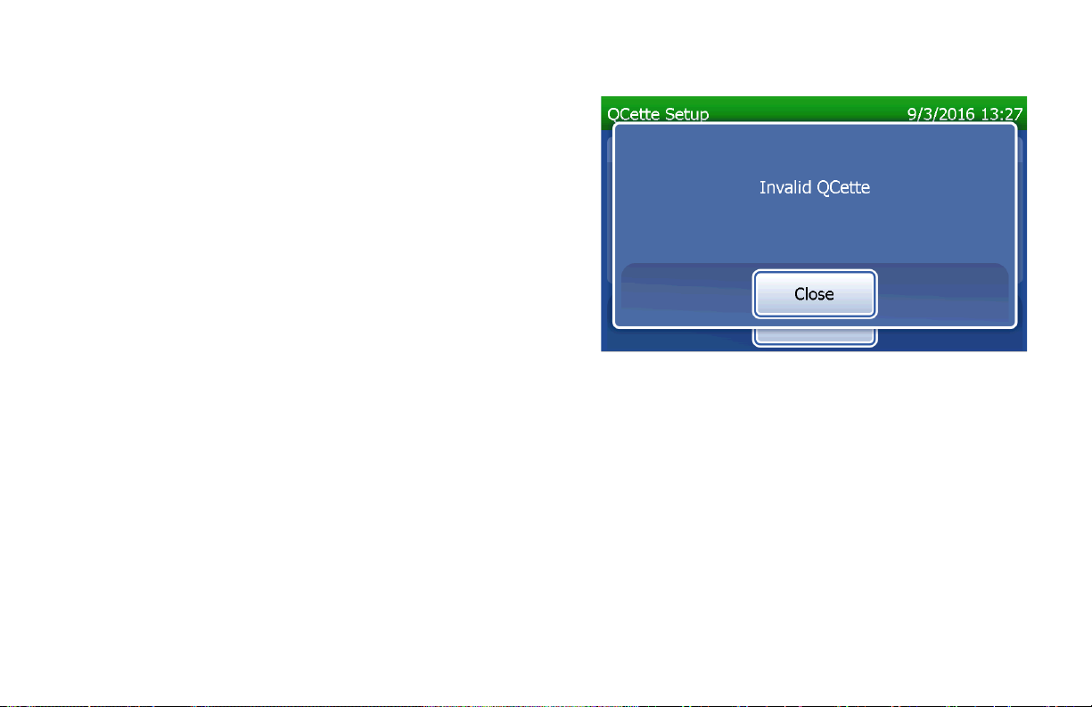
This message will be displayed if the QCette serial
number entered is not identical to the serial number
entered at the time of QCette setup.
Press Close. Either set up a new QCette, or re-do Run
QCette QC with the correct QCette.
PeriLynx™ System User Manual
Section 4 — Software Functions — Run QCette QC
4-16
Page 60
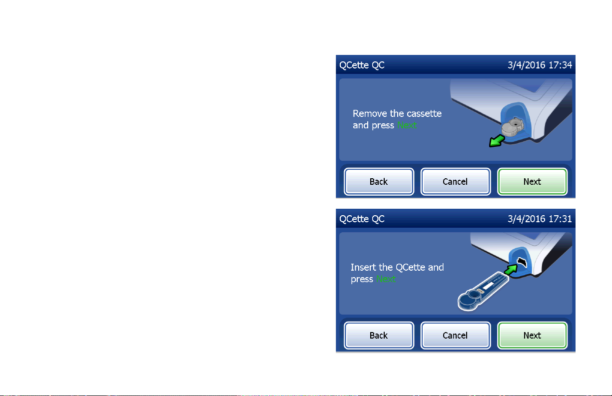
This screen will be displayed if a cassette is present in
the analyzer prior to reaching the next screen. Remove
cassette and press Next.
The analyzer then prompts the user to insert the QCette
and press Next.
PeriLynx™ System User Manual
Section 4 — Software Functions — Run QCette QC
4-17
Page 61
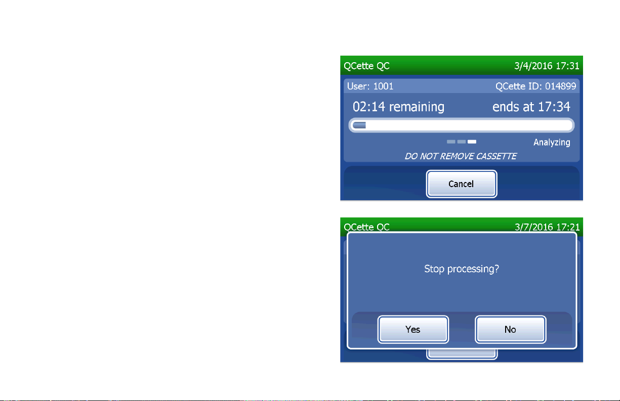
The analyzer will read the QCette. Do not disturb the
analyzer until the results are displayed. The analysis will
take approximately 2–3 minutes.
This message will be displayed if Cancel was pressed
during testing. Select Yes to stop processing or No to
continue the test. This message will hold for 5 seconds
and then continues the test. If the test is cancelled,
remove the cassette and press Finish test.
PeriLynx™ System User Manual
Section 4 — Software Functions — Run QCette QC
4-18
Page 62

QCette data record
The complete record will be printed automatically if Auto Print is set to ON, or it may be printed/reprinted by
pressing the Print button.
QCette results are SYSTEM: PASS or SYSTEM: FAIL. The analyzer displays the PASS or FAIL result and the
result for each QCette level (Level 1 and Level 2).
A FAIL result should be repeated. (See Section 7 — Troubleshooting, Items 8 and 9.)
Press Finish to return to the Main Menu.
Display and Printout
PeriLynx™ System User Manual
Section 4 — Software Functions — Run QCette QC
4-19
Page 63

Liquid Controls
On the Main Menu, select Run Liquid QC to run the liquid
controls.
The User ID must be entered to proceed to the next
step. Press Next to accept the ID. This field will accept
15alphanumeric characters.
PeriLynx™ System User Manual
Section 4 — Software Functions — Liquid Controls
4-20
Page 64
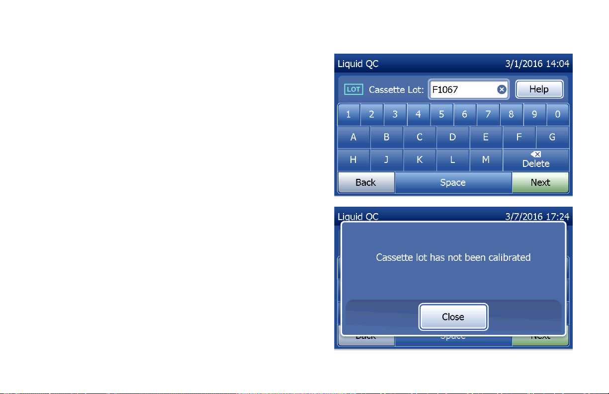
The Cassette Lot number must be entered to proceed to
the next step. The Cassette Lot is located on the cassette
pouch and the cassette box. The software requires that
the lot number is entered in the correct format: one alpha
character followed by four numeric characters (e.g., F1067).
The analyzer automatically compares the Cassette Lot
number used to set calibration with the cassette lot number
used for testing controls.
If the cassette lot numbers do not match, the test
process cannot continue. When this occurs, the display
says that the cassette lot has not been calibrated. Press
Close and the cassette lot number used for calibration
will be displayed.
PeriLynx™ System User Manual
Section 4 — Software Functions — Liquid Controls
4-21
Page 65

Select Level 1 control or Level 2 control.
Enter the control lot number and press Next. This field will
accept up to 12alphanumeric characters.
PeriLynx™ System User Manual
Section 4 — Software Functions — Liquid Controls
4-22
Page 66

This message will be displayed if a cassette is present
in the analyzer prior to reaching the next screen.
Remove cassette and press Next.
The analyzer then prompts the user to insert the cassette
and press Next.
PeriLynx™ System User Manual
Section 4 — Software Functions — Liquid Controls
4-23
Page 67

The analyzer will check that a RapidfFN10Q Cassette is
properly inserted.
A 30-second timer starts during which time the analyzer
beeps. Add 200µL of control sample and immediately
press Start Test.
PeriLynx™ System User Manual
Section 4 — Software Functions — Liquid Controls
4-24
Page 68
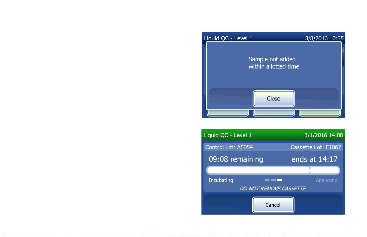
If the liquid control sample is not added and Start Test
is not pressed within allotted time, the test process
cannot continue. The display says that the sample was
not added in time. Press Close, remove the cassette,
and press Finish to return to the Main Menu. No record
of the test will be held in memory.
Once the sample is added, the analyzer will begin a
10-minute countdown.
To abort the test, press Cancel. Pressing Cancel and
then confirming that you want to stop the process will
terminate the test and the data will be lost.
Upon completion of the 7-minute incubation period, the
analyzer will begin the analysis of the cassette. Do not
disturb the analyzer until the results are displayed. The
analysis will take approximately 2–3 minutes.
PeriLynx™ System User Manual
Section 4 — Software Functions — Liquid Controls
4-25
Page 69
This message will be displayed if Cancel was pressed
during testing. Select Yes to stop processing or No to
continue the test. This message will hold for 5seconds and
then continues the test. If the test is cancelled, remove the
cassette and press Finish test. If the test is cancelled, a
new cassette will be required to repeat the test.
PeriLynx™ System User Manual
Section 4 — Software Functions — Liquid Controls
4-26
Page 70

Liquid control data record
The complete record will be printed automatically if Auto Print is set to ON, or it may be printed/reprinted by
pressing the Print button.
Control results are displayed as the fFN concentration in ng/mL or as INVALID. Refer to the Rapid fFN Control
Kit directional insert for acceptable results for the liquid controls.
An out-of-range result or an INVALID result should be repeated. (See Section 7 — Troubleshooting, Items 10
and 11.)
Display and Printout
PeriLynx™ System User Manual
Section 4 — Software Functions — Liquid Controls
4-27
Page 71

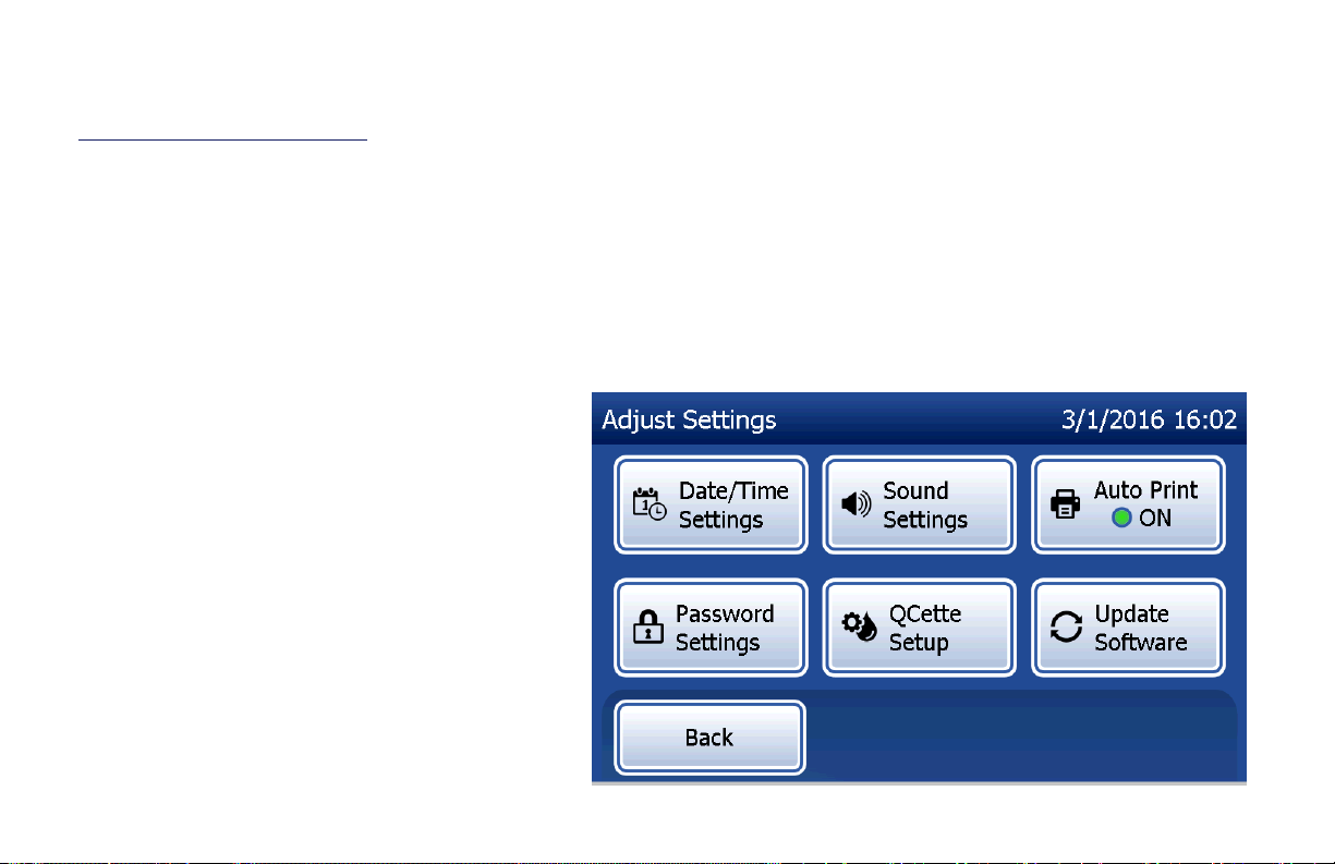
Adjust Settings
The Adjust Settings button on the Main Menu screen
allows the user to change the Date/Time, adjust the Sound
Settings,
Auto Print
, change the Password Settings or to
perform QCette Setup. This option also allows Hologic
Technical Support to update the software version. Press
the Adjust Settings button on the Main Menu to access
the Adjust Settings screen.
Adjust Settings — Date/Time
Select Date/Time Settings.
PeriLynx™ System User Manual
Section 4 — Software Functions — Adjust Settings
4-28
Page 72
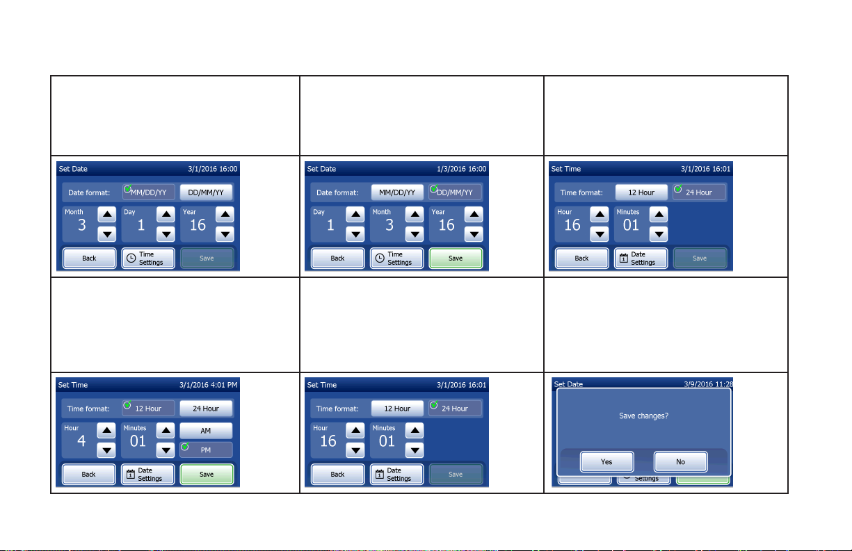
Set the date. In the Date format area,
select the preferred format. The green
check marks indicates the selection.
Use the up or down arrow to change the
time. When the time is set in the 12-hour
format, choose AM or PM. The green
check mark indicates the selection. Press
the Save button to accept.
Use the up or down arrow to change the
date. Press the Save button to accept.
From the Set Time screen, you have
the option to return to the Date Settings
screen. Or, press the Back button to
return to the Adjust Settings screen.
To change the time settings, press the
Time Settings button.
In the Time format area, select the
preferred format. The green check mark
indicates the selection.
If there are any unsaved changes and the
Back button, Date Settings button, or
Time Settings button is pressed, a “Save
changes” screen is displayed. Press Yes
to save changes or No to discard the
changes.
PeriLynx™ System User Manual
Section 4 — Software Functions — Adjust Settings
4-29
Page 73

Adjust Settings — Sound Settings
In the Sound Settings section, select whether the audible tone (beep) will be on or off. A green check mark
indicates the selection.
If the sound is turned on, use the plus (+) or minus (-) buttons to increase or decrease the audio volume. If the
sound is turned on, touching the plus or minus buttons also makes the analyzer play the sound at that volume.
Press the Back button to return to the Adjust Settings screen.
PeriLynx™ System User Manual
Section 4 — Software Functions — Adjust Settings
4-30
Page 74

Adjust Settings — Auto Print
On the Adjust Settings screen, press the Auto Print button to change whether the Auto Print feature is on or off.
A green circle indicates that Auto Print is on.
Auto Print automatically prints test results when set in the ON position. When Auto Print is OFF, results may be
printed by pressing the Print button.
Auto Print ON Auto Print OFF
PeriLynx™ System User Manual
Section 4 — Software Functions — Adjust Settings
4-31
Page 75

Adjust Settings — Password Settings
The analyzer can be set so that a password is required
to view and print patient information in the Access Data
section.
If the password protection is disabled, the Access Data
features are available to all users.
If the password protection is disabled, to enable the
password protection, touch the Enter New Password
button.
PeriLynx™ System User Manual
Section 4 — Software Functions — Adjust Settings
4-32
Page 76
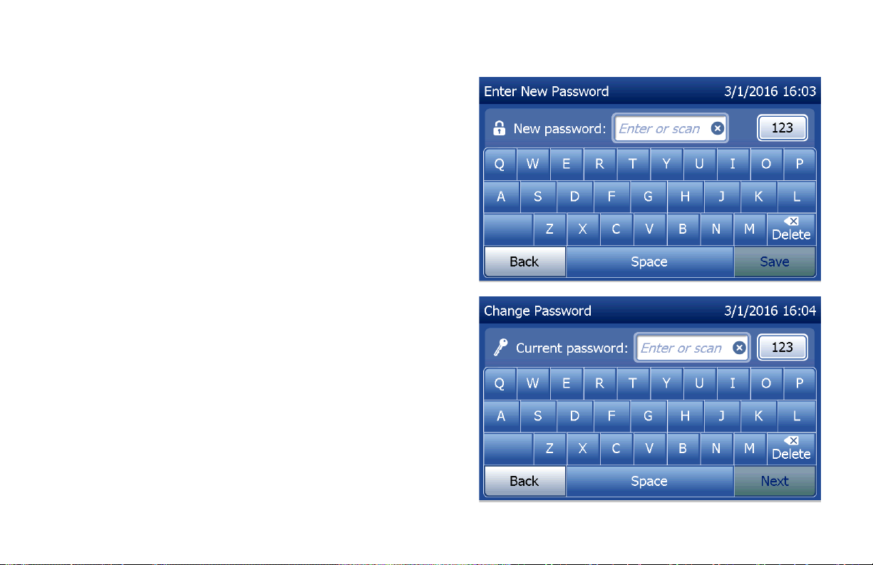
Use the touch screen or the optional barcode scanner to
enter the password.
Press the Save button.
A password is now required to view or print the information
in the Access Data section.
To change the password, press the Change Password
button. Use the touch screen or the optional barcode
scanner to enter the current password. Press the Next
button, and then enter the new password.
Press the Save button.
PeriLynx™ System User Manual
Section 4 — Software Functions — Adjust Settings
4-33
Page 77

To remove the password protection, press the Remove
Password button. Use the touch screen or the optional
barcode scanner to enter the current password.
Press the Next button.
The password protection changes from “Enabled” to
“Disabled”. No password is required to view or print the
information in the Access Data section.
PeriLynx™ System User Manual
Section 4 — Software Functions — Adjust Settings
4-34
Page 78

Adjust Settings — QCette Setup
The QCette Setup initializes the QCette for use in evaluating
the performance of the analyzer. During the initialization
process, the performance criteria of the analyzer are
established. QCette Setup must be performed PRIOR to
running the QCette as a quality control device.
From the Main Menu, select Adjust Settings.
Select QCette Setup on the Adjust Settings menu to begin.
Enter the User ID to proceed to the next step. Press Next
to accept the ID. This field will accept 15alpha and/or
numeric characters.
PeriLynx™ System User Manual
Section 4 — Software Functions — Adjust Settings
4-35
Page 79

The QCette ID must be entered to proceed to the next step.
The QCette ID is the serial number for the QCette. The
serial number is printed on the QCette plastic housing. The
software requires that the serial number is entered in the
correct format: six numeric characters (e.g., 014899). Enter
all leading zeros.
This message will be displayed if a cassette is present
in the analyzer prior to reaching the next screen.
Remove cassette and press Next.
PeriLynx™ System User Manual
Section 4 — Software Functions — Adjust Settings
4-36
Page 80

The analyzer then prompts the user to insert the QCette
and press Next.
A ten-minute timer starts.
The analyzer will begin initializing the QCette. Do not disturb
the analyzer until the results are displayed. The initialization
process will take approximately 10 minutes. Initialization
can be terminated by pressing Cancel.
PeriLynx™ System User Manual
Section 4 — Software Functions — Adjust Settings
4-37
Page 81

This message will be displayed if Cancel was pressed
during testing. Select Yes to stop processing or No to
continue the test. This message will hold for 5seconds
and then continues the test. If the test is cancelled,
remove the cassette and press Finish test.
PeriLynx™ System User Manual
Section 4 — Software Functions — Adjust Settings
4-38
Page 82
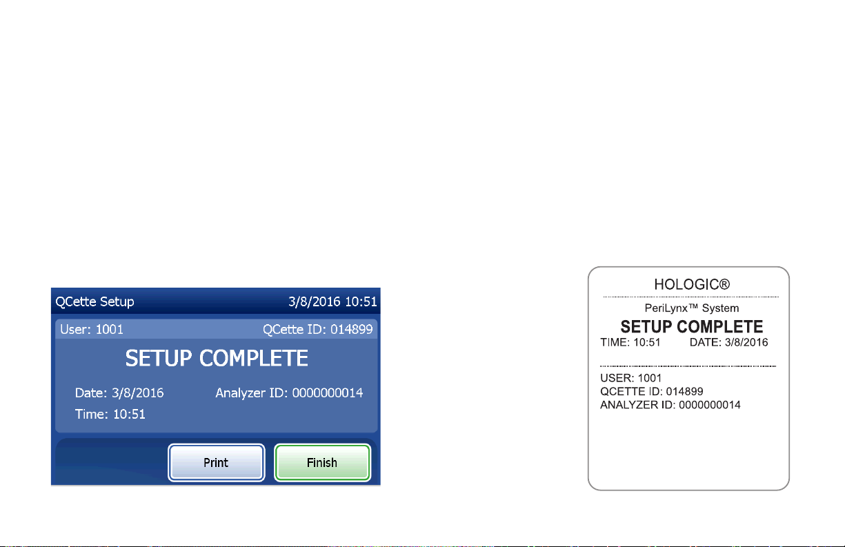
Upon successful completion of the QCette Setup, this message will be displayed. SETUP COMPLETE indicates
that the performance criteria of the analyzer have been established. Press Finish to return to the Main Menu.
Display and Printout
PeriLynx™ System User Manual
Section 4 — Software Functions — Adjust Settings
4-39
Page 83
This message will be displayed if the QCette Setup is
not completed. It indicates that the performance criteria
of the analyzer have not been established. If the QCette
setup error occurs, see Section 7 — Troubleshooting,
Item 8.
PeriLynx™ System User Manual
Section 4 — Software Functions — Adjust Settings
4-40
Page 84

Adjust Settings — Update Software
The Adjust Settings screen has an option which allows the
software version to be updated.
PeriLynx™ System User Manual
Section 4 — Software Functions — Adjust Settings
4-41
Page 85

View Reports
From the Main Menu, the View Reports button allows the
user to view and print the monthly usage report, the test
counts, and the Access Data functions.
Monthly Usage
On the View Reports screen, touch the Monthly Usage
button to view or print a summary of patient tests
performed for each month in the past 12months (rolling
calendar).
Note: to transfer the monthly usage report to a USB
device, connect a USB drive to any USB port on
the back of the analyzer before you touch the
Monthly Usage button on the View Reports
screen.
PeriLynx™ System User Manual
Section 4 — Software Functions — View Reports
4-42
Page 86
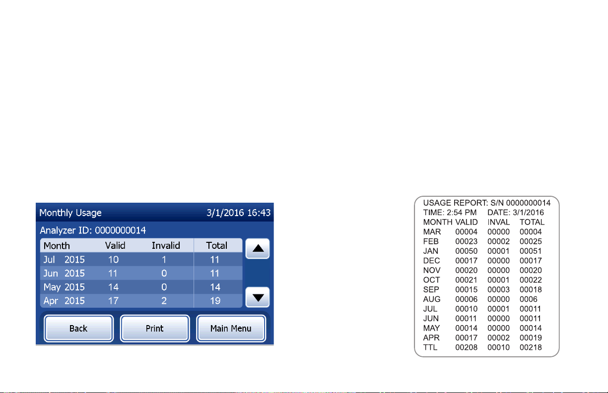
Use the up or down arrow to scroll through the report.
The total number of patient tests is displayed. The total number of valid patient tests and the total number of
invalid patient tests are also displayed.
Print the report by pressing the Print button.
Press the Back button to return to the View Reports screen.
Press the Main Menu button to return to the Main Menu.
Display and Printout
PeriLynx™ System User Manual
Section 4 — Software Functions — Monthly Usage
4-43
Page 87

Test Counts
On the View Reports screen, touch the Test Counts button
to view and print the number of tests by category that were
performed on the analyzer.
The total numbers of patient tests, liquid control tests
(Liquid QC), and QCette QC tests are displayed.
Press the Print button to print Test Counts Report (TCR).
Press the Back button to return to the View Reports screen.
Press the Main Menu button to return to the Main Menu.
Display and Printout
PeriLynx™ System User Manual
Section 4 — Software Functions — Test Counts
4-44
Page 88

Access Data
Access Data — View/Print Data
On the View Reports screen, touch the Access Data button to access the patient data, QCette QC data, Liquid QC data or Calibration data stored in the analyzer.
Select the category of data records to view and/or print.
PeriLynx™ System User Manual
Section 4 — Software Functions — Access Data
4-45
Page 89

If the password protection is enabled on the analyzer, to
access patient data, enter the password and press Next.
A summary of data records for the category is displayed,
with the newest record at the top of the list. Patient data
was chosen for this example. Use the up or down arrow to
scroll through the summaries.
PeriLynx™ System User Manual
Section 4 — Software Functions — Access Data
4-46
Page 90

To view a data record, click on the entry. Use the up or
down arrow to scroll through different data records.
Press the Print button to print the data record.
Press the Back button to return to the previous screen.
Press the Main Menu button to return to the Main Menu.
Access Data — Data Transfer
On the Access Data menu, the Transfer Data feature allows
the user to transfer all of the test results stored on the
analyzer to a computer connected to the analyzer through a
serial cable.
Note: A maximum of 1000patient test results,
50QCette QC results, 50Liquid QC results, and
50Calibration results are stored on the analyzer.
PeriLynx™ System User Manual
Section 4 — Software Functions — Access Data
4-47
Page 91

Touch Transfer Data.
If the password protection is enabled on the analyzer, enter
the password and press Next.
Note: Data transferred to a computer is in ASCII format.
Capture and organization of the transferred data
is done at the discretion of the user. Hologic, Inc.
DOES NOT provide software or technical support
relating to the manipulation of data once it has
left the analyzer.
This message will be displayed while the data transfer is in
process.
When the transfer is complete, the View Reports screen
displays.
PeriLynx™ System User Manual
Section 4 — Software Functions — Access Data
4-48
Page 92

Section 5 — Care of the Analyzer
General Cleaning
Keep the analyzer free of dust. If needed, clean the exterior, including the touch screen, with a damp cloth and
mild detergent.
WARNING: Liquids MUST NOT be allowed to seep into the analyzer. Keep the analyzer dry at all
times. Liquids leaking into the analyzer may cause damage to the electrical components or possibly
electrical shock to the user.
CAUTION: DO NOT use solvents of any type on any part of the analyzer. Solvents can damage the touch screen
display.
Cleaning of Cassette Insertion Site
The cassette insertion site can come into contact with biological fluids and should be cleaned regularly.
CAUTION: Use appropriate laboratory procedures for handling biohazardous materials.
Cleaning Agents Approved for Use
Reagents not listed below may cause discoloration to the analyzer case and touch screen.
The following cleaning agents may be applied with a cloth or lab wiper only. NEVER apply agents by spray.
• 70% ethanol
• General laboratory cleaning detergent with disinfectant properties
PeriLynx™ System User Manual
Section 5 — Care of the Anaylzer
5-1
Page 93

Section 6 — Printer
Loading Printer Labels
Refer to Section 2 — Installation, for instructions on connecting the printer to the PeriLynxanalyzer.
Note: DO NOT install any of the Dymo Label software that is packaged with the printer.
1. Open the printer cover for access to the interior of the printer. Remove any packing material.
2. Remove the label spool from the printer.
3. Notice that the label spool has distinct LEFT and RIGHT sides. Refer to the illustration on each piece for
correct assembly. The right side slides in and out and can be removed entirely to load label rolls.
4. Remove the RIGHT SIDE of the spool by sliding it off the right end.
PeriLynx™ System User Manual
Section 6 — Printer
6-1
Page 94

5. Refer to Figure1 while following these instructions:
Slide the roll of labels over the spool from right to left
as shown in Figure 1(a). Then reattach the right side
of the spool and push it firmly against the label roll
as shown in Figure1(b). Make sure there is no gap
between the roll and the spool. The labels will feed
from the bottom of the roll.
6. Ensure the power cord is connected. Turn on the
printer by plugging it in to a power outlet. The power
light will flash and the printer motor will run as it looks
for labels to feed.
7. Holding the spool of labels in one hand, use the other
hand to feed the free end of the roll into the feed slot
on the inside of the printer, as shown in Figure2. (If it
is easier, rest the labels on the top edge of the printer,
freeing both hands to feed the labels.)
Figure 1
a
b
PeriLynx™ System User Manual
Section 6 — Printer
6-2
Page 95

8. Push the end into the slot until a slight resistance is felt. Continue
pushing gently. The label feed motor will feed the end and carry the
labels through the printer and out the exit slot. The printer will stop
feeding automatically at the end of the first label. If the motor stops
running while still in the process of loading labels, press the form
feed button to get it started again. (To protect itself the motor stops
running every few seconds.)
9. Insert the label spool into the printer. The spool will fit into the raised
shoulder slots in the printer.
10. Close the cover and the printer is ready to print labels.
Figure 2
PeriLynx™ System User Manual
Section 6 — Printer
6-3
Page 96

Removing an Empty Label Roll
When the printer is out of labels, the power light will flash.
1. Leave the printer turned on and open the cover. The last label on the roll may be connected to the
corrugated core by a piece of tape. If it is, use scissors to cut the label between the roll and the label feed
slot. Remove the label spool from the printer.
2. Press the Form Feed button on the printer’s front panel to eject the remaining label stock from the printer.
3. Slide off the right side of the spool and remove the corrugated core.
4. Load a new roll of labels (see Loading Printer Labels for instructions).
PeriLynx™ System User Manual
Section 6 — Printer
6-4
Page 97

Clearing Label Jams
Note: To prevent label jams, tear off printouts as they are generated. Do not let the label roll scroll out of
the printer.
If the labels jam in the printer, follow these steps to remove them.
1. Open the printer cover and use scissors to cut the label between the feed slot and the roll of labels.
2. Press the Form Feed button on the printer’s front panel to advance the label through the printer. Reload
the labels (see Removing an Empty Label Roll for instructions).
3. If the label will not come through the form feed slot, remove the label spool from the printer. Pull the
jammed label gently back out of the printer through the feed slot.
4. If needed, the front bezel of the printer may be removed to better access the print head. Open the lid and
gently pull up on the lip of the front cover (1, see below). Slide the piece forward (2). The bezel will pull off.
PeriLynx™ System User Manual
Section 6 — Printer
6-5
Page 98

5. Press the level on the left of the printer forward to release the pressure of the print head against the label.
6. To reassemble the printer bezel, slide the cover back on, making sure to engage the tabs that are on the
bottom as well as the top. Reload the roll of labels.
1
2
PeriLynx™ System User Manual
Section 6 — Printer
6-6
Page 99

Section 7 — Troubleshooting
General Information
The PeriLynxanalyzer software is designed for easy troubleshooting. Always heed the beep tones and follow
the display screen prompts to obtain the best performance from your system. The following table lists potential
problems, sources of trouble, and recommended solutions. Call Hologic Technical Support for any questions
related to the performance of your PeriLynxsystem.
ITEM PROBLEM SOURCE SOLUTION
1 Analyzer display
screen is blank.
Analyzer power
cord and/or
adapter
Ensure analyzer power cord is rmly connected to analyzer.
Ensure analyzer power adapter is the adapter provided with
analyzer.
Ensure analyzer power adapter is plugged into a grounded
AC electrical outlet.
On/off switch Ensure analyzer on/off switch is in the on position.
PeriLynx™ System User Manual
Section 7 — Troubleshooting
7-1
Page 100

ITEM PROBLEM SOURCE SOLUTION
2 Error code is
analyzer Turn analyzer off and back on to reinitialize the system.
displayed when
analyzer is rst
If the Error Code persists, refer to Error/Invalid Code table.
turned on.
3 Analysis process
is interrupted
and/or unusual
Momentary
power
interruption
Disconnect the printer power cord from the analyzer.
Turn off the analyzer.
characters
appear on
Reconnect the printer power cord to the analyzer.
display screen,
and the
Turn on the analyzer.
analyzer does
not respond to
Proceed with testing.
touch screen
selections.
PeriLynx™ System User Manual
Section 7 — Troubleshooting
7-2
 Loading...