

Page 1
DISCOVERY
™
QDR® Series
FAN BEAM X-RAY BONE DENSITOMETER
TECHNICAL MANUAL
Hologic, Inc.
35 Crosby Drive
Bedford, MA 01730
USA
Phone in US: 800-321-4659
Fax (Domestic): 781-280-0670
Fax (International): 781-280-0671
Document 080-1085
Revision 008
Page 2

Discovery QDR Series Technical Manual
December 2010
Notice
The information contained in this manual is confidential and proprietary to Hologic, Inc.
This information is provided only to authorized representatives of Hologic's customers
solely for the purpose of facilitating the use of Hologic's products. No information
contained herein may be disclosed to any unauthorized person for any purpose whatsoever
without the prior written consent of Hologic, Inc.
The procedures described in this document are intended for use by direct employees of
Hologic, Inc., or authorized Hologic Equipment Resellers and their trained field
engineers. Any unauthorized or untrained persons performing these procedures may affect
the warranty of the Discovery QDR Series.
Exercise proper caution when servicing the system. There are dangerous and potentially
lethal voltages accessible within the Discovery system. To avoid exposure to shock
hazards, the Main Circuit Breaker should be switched off, and the power cord removed,
before working inside any part of the system.
The Discovery QDR Series Fan Beam X-ray Bone Densitometer produces ionizing
radiation in the form of X-rays. It may be dangerous to the patient, operator or field
engineer unless safe exposure factors and operating instructions are observed. To avoid
unsafe exposure, do not attempt to service the equipment unless you are a Hologic, Inc.,
certified field engineers. Exercise proper caution when servicing the system. A dosimeter
(film badge) should always be worn while on site. Dose and scatter measurements must be
taken after each service call to ensure that the parameters are still within specifications.
Hologic, Inc., has made all effort to ensure that the information in this manual is accurate
and complete. Hologic, Inc., shall not, however, be liable for any technical or editorial
errors or omissions contained herein, or for incidental, special or consequential dangers in
connection with the furnishing or use of this manual. The information in this manual is
subject to change without notice.
Discovery and the Hologic logo are registered trademarks of Hologic, Inc. All other
products and company names used in this manual are trademarks and registered
trademarks of other manufactures.
Printed in U.S.A.
Copyright© 2003-2010 by Hologic, Inc., All rights reserved
ii
Page 3

Discovery QDR Series Technical Manual
Chapter 1 -
INTRODUCTION
1.1 System Overview ............................................................................................... 1-1
1.1.1 X-Ray Scanning Principles ....................................................................... 1-2
1.2 Functional Overview .......................................................................................... 1-4
1.3 Product Specifications ..................................................................................... 1-10
1.3.1 Exam Mode(s) Performance ................................................................... 1-12
1.3.2 Duty Cycle: ............................................................................................. 1-13
1.3.3 Leakage Technique Factors .................................................................... 1-13
1.3.4 Minimum Beam Filtration ...................................................................... 1-13
1.3.5 Measured Half Value Layer (HVL) At Different Operating Potentials . 1-13
1.3.6 Line Voltage and Maximum Line Current ............................................. 1-13
1.3.7 Technique Factors for Maximum Line Current ...................................... 1-13
1.3.8 Maximum Deviation ............................................................................... 1-14
1.3.9 Measurement Criteria for Technique Factors ......................................... 1-14
Chapter 2 -
FUNCTIONAL DESCRIPTION
2.1 Computer ........................................................................................................... 2-1
2.2 PCI Communications Controller Board ............................................................. 2-1
2.2.1 Interface Connections ............................................................................... 2-1
2.3 Distribution Board ............................................................................................. 2-3
2.3.1 Power ........................................................................................................ 2-3
2.3.2 Interface Connections ............................................................................... 2-4
2.4 Motor Controller Board ..................................................................................... 2-5
2.4.1 Power ........................................................................................................ 2-5
2.4.2 Interface Connections ............................................................................... 2-6
2.5 TZ Drive Board (A and SL Only) ...................................................................... 2-6
2.5.1 Service Switches ....................................................................................... 2-7
2.5.2 Power ........................................................................................................ 2-7
2.5.3 Interface Connections ............................................................................... 2-8
2.6 Control Panel Controller Board ....................................................................... 2-10
2.6.1 Power ...................................................................................................... 2-10
2.6.2 Interface Connections ............................................................................. 2-10
2.7 C-Arm Interface Board .................................................................................... 2-12
2.7.1 Continuity Daisy Chain .......................................................................... 2-13
2.7.2 Power ...................................................................................................... 2-13
2.7.3 Interface Connections ............................................................................. 2-13
2.8 X-Ray Controller Assembly (P/N 010-1273) .................................................. 2-16
2.8.1 Interface .................................................................................................. 2-16
Table of Contents iii
Page 4

Discovery QDR Series Technical Manual
2.8.2 X-Ray Controller Board .......................................................................... 2-18
2.9 X-Ray Source Unit ........................................................................................... 2-19
2.10 Data Acquisition System (C, W, and SL) ..................................................... 2-20
2.10.1 Solid State Detector ............................................................................. 2-20
2.10.2 Integrator/Multiplexor Subsection ........................................................ 2-20
2.10.3 Analog To Digital Board ...................................................................... 2-21
2.10.4 Power .................................................................................................... 2-21
2.10.5 Interface Connections ........................................................................... 2-21
2.11 Data Acquisition System (A Model only) ..................................................... 2-23
2.11.1 Solid State Detector ............................................................................. 2-23
2.11.2 Power .................................................................................................... 2-23
2.11.3 Interface Connections ........................................................................... 2-23
2.12 Integrator/Multiplexor Board ......................................................................... 2-24
2.12.1 Power .................................................................................................... 2-25
2.12.2 Interface Connections ........................................................................... 2-25
2.13 Analog To Digital Board (A Model Only) .................................................... 2-27
2.13.1 Power .................................................................................................... 2-27
2.13.2 Interface Connections ........................................................................... 2-27
2.14 Torroid Power Module and DIN Rail ............................................................ 2-29
Chapter 3 -
INSTALLATION
3.1 Pre-Installation Requirements ............................................................................ 3-1
3.1.1 Required Tools .......................................................................................... 3-1
3.1.2 Required Documentation .......................................................................... 3-1
3.1.3 Room and Doorway Size .......................................................................... 3-2
3.1.4 Arrange For Help ...................................................................................... 3-6
3.2 Uncrate and Move to Destination ...................................................................... 3-6
3.2.1 Inspect For Shipping Damage ................................................................... 3-6
3.2.2 Uncrate Unit .............................................................................................. 3-7
3.2.3 Take Inventory .......................................................................................... 3-8
3.2.4 Measure Path To Final Destination .......................................................... 3-8
3.2.5 Remove Tabletop (If Necessary) .............................................................. 3-9
3.2.6 Remove Discovery A or SL Lower C-Arm Assembly (If Necessary) ... 3-10
3.2.7 Prepare the Tabletop for Moving (A, W,Wi) .......................................... 3-12
3.2.8 Move Unit To Destination ...................................................................... 3-12
3.2.9 Set Up the Unit ....................................................................................... 3-16
3.3 Install the System ............................................................................................. 3-18
3.3.1 Install Cables ........................................................................................... 3-18
3.3.2 Check Power Line Voltage ..................................................................... 3-23
3.3.3 Install Computer ..................................................................................... 3-24
iv Table of Contents
Page 5

Discovery QDR Series Technical Manual
3.3.4 Start QDR Software in Service Mode ..................................................... 3-24
3.3.5 Check Table Alignment .......................................................................... 3-25
3.3.6 Perform C-Arm Parallelism Adjustment (A and SL systems only) ........ 3-27
3.4 Calibrate and Test the System ......................................................................... 3-28
3.4.1 Check Tube kV Peak Potential ............................................................... 3-28
3.4.2 Check Tube Current ............................................................................... 3-30
3.4.3 Adjust Belt Tension ................................................................................ 3-32
3.4.4 Calibrate Motors ..................................................................................... 3-33
3.4.5 X-Ray Beam Alignment ........................................................................ 3-47
3.4.6 Calibrate Aperture (Cannot be run on Ci and Wi models) ..................... 3-53
3.4.7 Check Laser Positioning Offset .............................................................. 3-54
3.5 A/D Gain Control Adjustment ......................................................................... 3-54
3.5.1 Check and Verify the A/D Gain ............................................................. 3-54
3.5.2 Adjust the A/D Gain ............................................................................... 3-55
3.5.3 Perform Detector Flattening .................................................................. 3-55
3.5.4 Perform Lateral Alignment Test (A and SL) .......................................... 3-56
3.5.5 Check HVPS/S (Tank) For Radiation Leakage ...................................... 3-58
3.5.6 Calibrate For Area, BMD And BMC ...................................................... 3-60
3.5.7 Scan Thickness Measurement & Calibration (C and W) ........................ 3-61
3.5.8 Scan Thickness Measurement & Calibration (A and SL) ....................... 3-61
3.5.9 Calibration of Area and BMC, for Array Scan Modes ........................... 3-62
3.5.10 RECALYZE and Add Array AP Scans to the QC Database ................ 3-63
3.5.11 Install Software Options ....................................................................... 3-64
3.5.12 Test Scan Modes ................................................................................... 3-64
3.5.13 Finish Assembling Unit ........................................................................ 3-66
3.5.14 Measure X-Ray Dose To Patient .......................................................... 3-66
3.5.15 Measure X-Ray Scatter From Phantom ................................................ 3-67
3.5.16 Perform QC ........................................................................................... 3-67
3.5.17 Run Reproducibility Test ...................................................................... 3-67
3.5.18 Table Top Radiographic Uniformity (A, W and Wi) ........................... 3-68
3.5.19 Instruments using Body Composition Analysis (BCA) ........................ 3-69
3.5.20 Instruments using BMD Whole Body Analysis ................................... 3-70
3.6 The Radiation Measurement Report ................................................................ 3-70
Chapter 4 -
ALIGNMENT AND CALIBRATION
4.1 Check Table Alignment ..................................................................................... 4-1
4.2 Align the Table .................................................................................................. 4-1
4.2.1 Table Edge to T-Rail (“A” Dimension) Adjustment ................................ 4-1
4.2.2 Front to Back T-Rail and Table Edge/Rail Gap Adjustment .................... 4-3
4.3 C-Arm Parallelism Adjustment ........................................................................ 4-3
4.4 X-Ray Beam Alignment ................................................................................... 4-4
4.5 Aperture Calibration ......................................................................................... 4-9
Table of Contents v
Page 6

Discovery QDR Series Technical Manual
4.6 Motor Calibration ............................................................................................ 4-10
4.7 Laser Positioning Offset Adjustment ............................................................... 4-26
4.8 A/D Gain Control Adjustment ......................................................................... 4-26
4.8.1 Check and Verify the A/D Gain ............................................................. 4-27
4.8.2 Adjust the A/D Gain ............................................................................... 4-27
4.9 Filter Drum Encoder Alignment ...................................................................... 4-28
4.10 Detector Flattening ....................................................................................... 4-29
4.11 Lateral Alignment Test (QDR 4500A and SL) .............................................. 4-30
4.12 Table Top Radiographic Uniformity ............................................................. 4-32
4.12.1 Instruments using Body Composition Analysis (BCA) ........................ 4-33
4.12.2 Instruments using BMD Whole Body Analysis ................................... 4-33
4.13 Check Phantom values ................................................................................... 4-34
4.14 Area, BMD, and BMC Calibration ................................................................ 4-34
4.14.1 Scan Thickness Measurement & Calibration (C and W) ...................... 4-35
4.14.2 Scan Thickness Measurement & Calibration (A and SL) ..................... 4-36
4.14.3 Calibration of Area and BMC, for Array Scan Modes ......................... 4-37
4.14.4 RECALYZE and Add Array AP Scans to the QC Database ................ 4-38
Chapter 5 -
REMOVE AND REPLACE PROCEDURES
5.1 Recommended Tools ......................................................................................... 5-1
5.2 Electronics Tray FRUS ...................................................................................... 5-1
5.2.1 Electronics Tray Printed Circuit Boards ................................................... 5-2
5.2.2 C-Arm Y Motor or Gearcase .................................................................... 5-3
5.2.3 C-Arm Y Encoder ..................................................................................... 5-4
5.3 Table Y FRUs (A, W and Wi Only) .................................................................. 5-4
5.3.1 Control Panel (All models) ....................................................................... 5-5
5.3.2 PCBs Under Right-Side of the Table ........................................................ 5-5
5.3.3 Table Y Belt .............................................................................................. 5-6
5.3.4 Table Y Motor or Gearcase ...................................................................... 5-7
5.3.5 Table Y Encoder ....................................................................................... 5-7
5.4 Table X FRUS ................................................................................................... 5-8
5.4.1 Table X Motor Controller PCB ................................................................ 5-9
5.4.2 Table X Belt ............................................................................................ 5-10
5.4.3 Table X Motor or Gearcase .................................................................... 5-10
5.4.4 Table X Encoder ..................................................................................... 5-11
5.5 Table Z FRUs (A and SL only) ...................................................................... 5-12
5.5.1 Pedestal ................................................................................................... 5-12
5.5.2 The Linear Rotary String (Encoder) ....................................................... 5-14
5.6 Lower C-Arm FRUS ........................................................................................ 5-16
vi Table of Contents
Page 7

Discovery QDR Series Technical Manual
5.6.1 C-Arm Interface Board ........................................................................... 5-17
5.6.2 X-Ray Controller Assembly ................................................................... 5-18
5.6.3 Filter Drum Assembly ............................................................................ 5-18
5.6.4 Tank Assembly ....................................................................................... 5-19
5.6.5 Arm R FRUS (A and SL only) ............................................................... 5-21
5.6.6 Motor Controller Board ......................................................................... 5-23
5.6.7 Arm R Belt .............................................................................................. 5-23
5.6.8 Arm R Motor, Gearcase, Encoder or Encoder Belt ................................ 5-24
5.6.9 Gas Spring ............................................................................................... 5-25
5.7 Upper C-Arm FRUS ........................................................................................ 5-25
5.7.1 Detector Assembly A, SL, W, C Systems .............................................. 5-26
5.7.2 Detector Assembly C1 and Wi Systems ................................................. 5-27
5.7.3 Laser Assembly ....................................................................................... 5-29
5.7.4 Analog to Digital Converter Board (A Model only) ............................... 5-30
5.8 Aperture Assembly FRUS ............................................................................... 5-31
5.8.1 Aperture Stepper Motor .......................................................................... 5-31
5.8.2 Aperture Motor PCB ............................................................................... 5-32
5.8.3 Aperture Position Belt ............................................................................ 5-32
5.8.4 Rotary Potentiometer .............................................................................. 5-33
5.9 Drum Assembly FRUS .................................................................................... 5-34
5.9.1 Drum Encoder PCB ................................................................................ 5-34
5.9.2 Drum Belts .............................................................................................. 5-36
5.9.3 Stepper Motor Assembly ........................................................................ 5-37
5.9.4 Drum Bearings ........................................................................................ 5-37
5.10 Replacing EMI Cables ................................................................................... 5-40
5.11 FRU Lists ....................................................................................................... 5-41
Chapter 6 -
FAULT ISOLATION
6.1 Before Starting ................................................................................................... 6-1
6.2 Software Configuration ...................................................................................... 6-1
6.3 Hardware Configuration .................................................................................... 6-1
6.4 Power Problems ................................................................................................. 6-1
6.5 Motion Problems ................................................................................................ 6-2
6.6 Control Panel Problems ..................................................................................... 6-5
6.7 Display Problems ............................................................................................... 6-5
6.7.1 Vertical Stripe ........................................................................................... 6-5
6.7.2 Horizontal Stripe ....................................................................................... 6-6
6.7.3 Noise ......................................................................................................... 6-7
6.7.4 No Display ................................................................................................ 6-7
6.8 Targeting/Laser Problems .................................................................................. 6-8
Table of Contents vii
Page 8

Discovery QDR Series Technical Manual
6.9 Data Communications Problems ....................................................................... 6-8
6.10 Area/BMD/BMC/CV Specification Problems ................................................. 6-9
6.11 X-Ray Problems ............................................................................................... 6-9
6.11.1 No X-Rays .............................................................................................. 6-9
6.12 X-Ray Alignment Problems ............................................................................. 6-9
6.12.1 X-Ray beam does not align properly ...................................................... 6-9
6.12.2 System Fails X-Ray Beam Alignment Verification ............................. 6-10
6.13 Detector Flattening Problems ........................................................................ 6-10
6.13.1 System Consistently Fails the Detector Flattening Procedure .............. 6-10
6.14 Laser Problems .............................................................................................. 6-11
6.15 Oil leakage ..................................................................................................... 6-12
6.15.1 The Torque Specifications .................................................................... 6-12
6.15.2 Tank Top Cover Components and Screw Location .............................. 6-12
6.15.3 Tightening the Lexan Cup Screws ........................................................ 6-13
6.15.4 Tightening the Bladder Gasket Screws ................................................. 6-13
6.15.5 Tightening the Transformer Seal Screws .............................................. 6-14
6.15.6 Tightening the Tank Cover Gasket Screws .......................................... 6-14
6.16 Miscellaneous Problems ................................................................................ 6-15
Chapter 7 -
PREVENTIVE MAINTENANCE
7.1 Customer Preventive Maintenance .................................................................... 7-1
7.2 Field Service Preventive Maintenance .............................................................. 7-1
7.2.1 Guide Rail and Bearing Maintenance ....................................................... 7-3
Chapter 8 -
PCB SUMMARY INFORMATION
Chapter 9 -
SOFTWARE TOOLS
9.1 X-Ray Survey .................................................................................................... 9-1
9.1.1 Invoking X-Ray Survey ............................................................................ 9-1
9.1.2 The Main Display ..................................................................................... 9-2
9.1.3 The Display Controls ................................................................................ 9-3
9.2 SQDRIVER ....................................................................................................... 9-9
9.3 SQVERIFY ...................................................................................................... 9-10
9.4 SQKEYPAD .................................................................................................... 9-10
Appendix A -
ERROR MESSAGES
viii Table of Contents
Page 9

Section 1
INTRODUCTION
1.1 System Overview
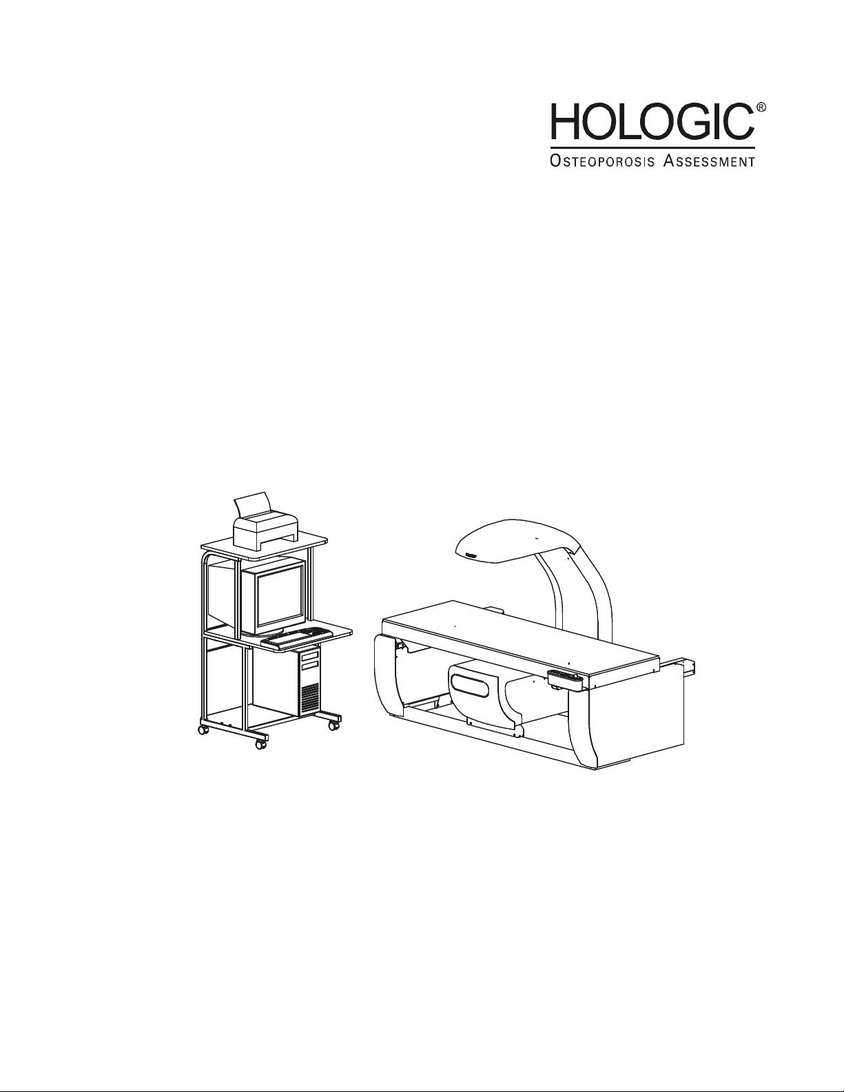
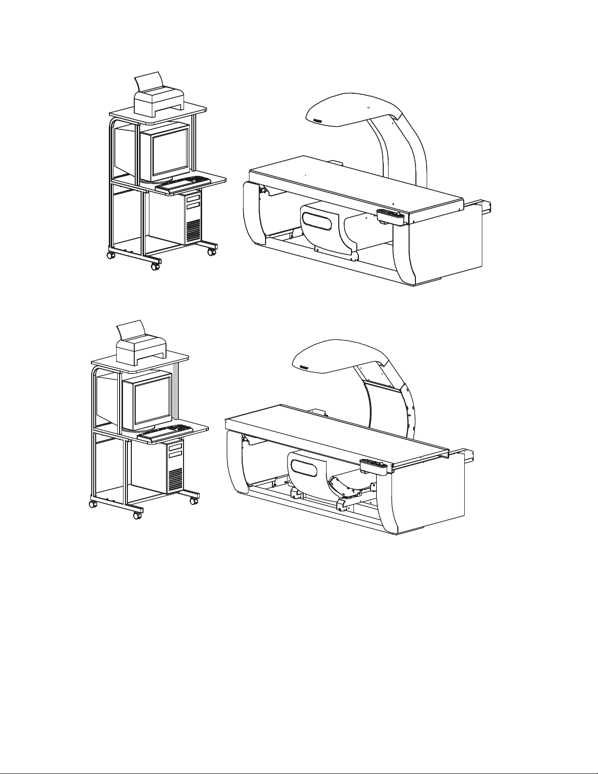
The Hologic Discovery® X-ray Bone Densitometer (Discovery-C and -W is shown in Figure 1-1
on Page 1-2; Discovery-A and -SL is shown in Figure 1-2 on Page 1-2) estimates the bone
mineral content (BMC) and bone mineral density (BMD) of selected areas of the body or of the
entire skeleton. It does so using X-rays of two different energy levels. This dual-energy scheme
allows soft tissue within the selected area to be subtracted out leaving only bone to be scanned
and estimated.
This manual uses "Discovery" to refer to all models in the Discovery series of systems.
Information presented in this manual that applies only to a particular model, or models, will be
noted as such.
The patient lies face up on the table and, with the aid of a cross-hair laser, the operator positions
the scanning arm over the region of interest. After entering patient data and selecting the type and
size of scan desired, the operator initiates the scan with a single keystroke.
The operator is not required to select technique factors as tube current and voltage are preselected and fixed. Since testing is performed by fan beam method, rather than by flooding the
area as in conventional radiography, the scanning time is a function of the dimensions of the area
to be measured, the desired resolution, and the desired precision.
BMC results are expressed in grams of calcium hydroxyapatite and BMD is reported in grams/
cm2 of the same compound.
In most cases, no additional shielding is necessary for patient, operator, or room. The Discovery
system can be placed in any convenient non-shielded examination room. Contact your state
regulatory agency for details about additional shielding requirements, if any.
The Discovery system employs a patented Automatic Internal Reference System, which
continuously calibrates the machine to eliminate the effects of variations in temperature, tube
flux, etc. No daily calibration is required. The daily scanning of a quality control phantom is
required to provide assurance that the system is functioning correctly and to aid in the detection of
any long-term drift.
The X-ray scans produced by the Discovery, and displayed on the monitor, are intended only to
locate anatomical sites for measurement and to assure the operator that the machine is operating
properly. They are not intended as a substitute for conventional film-based diagnostic scans.
1-1
Page 10
Discovery QDR Series Technical Manual
Figure 1-1. Discovery®-C and -W System
Figure 1-2. Discovery®-A and -SL System
1.1.1 X-Ray Scanning Principles
An X-ray source, consisting of a high voltage generator and X-ray tube in a common,
shielded enclosure, is mounted beneath the patient on the C-Arm. It generates a narrow,
tightly collimated, fan-shaped beam of X-rays which alternate, at power line frequency,
between 100kVp and 140kVp. At the other end of the C-Arm, above the patient, is a
crystal/solid state detector array. During a scan, the C-arm and table move, under
computer control, to guide the beam over the desired scan area.
1-2
Page 11

Discovery QDR Series Technical Manual
Before passing through the patient, the beam is filtered through a rotating drum in which
alternating segments having radio-opacities equivalent to tissue, bone and air are located.
When finally intercepted by the detector, the beam contains information about the X-ray
absorbing characteristics of both the patient and the calibration materials in the filter
drum. An A/D converter, fed by the detectors, supplies a complex digital signal to the
computer, which uses that signal both to construct the screen display, and as the basis for
its computations of BMC and BMD.
The Discovery computer algorithm is based on the principle that bone attenuates the X-ray
beam differently at high and low energies. The bone mineral content of any sample point
can be computed from:
Q= L - kH
where L and H are the logarithms of the sample attenuation at high (140kVp) and low
(100kVp) energies, respectively. The constant k depends on the tissue attenuation
characteristics of the beam. In the Discovery, k is continuously measured using the
“tissue” segment in the filter wheel.
The program works in the following manner:
1. Load preliminary scan and obtain regions of interest from operator.
2. Estimate k as an average value of:
k = [L
where L
tissue
interposed by the filter drum, and L
Note: The subscript "
- L
tissue
] / [H
air
tissue
- H
air
]
indicates a low-energy me as ureme nt with tissue -equi vale nt m aterial
, H
air
" designates the filter drum segment that is empty (i.e., contains
air
tissue
and H
are similarly defined.
air
neither bone- nor tissue-equivalent material).
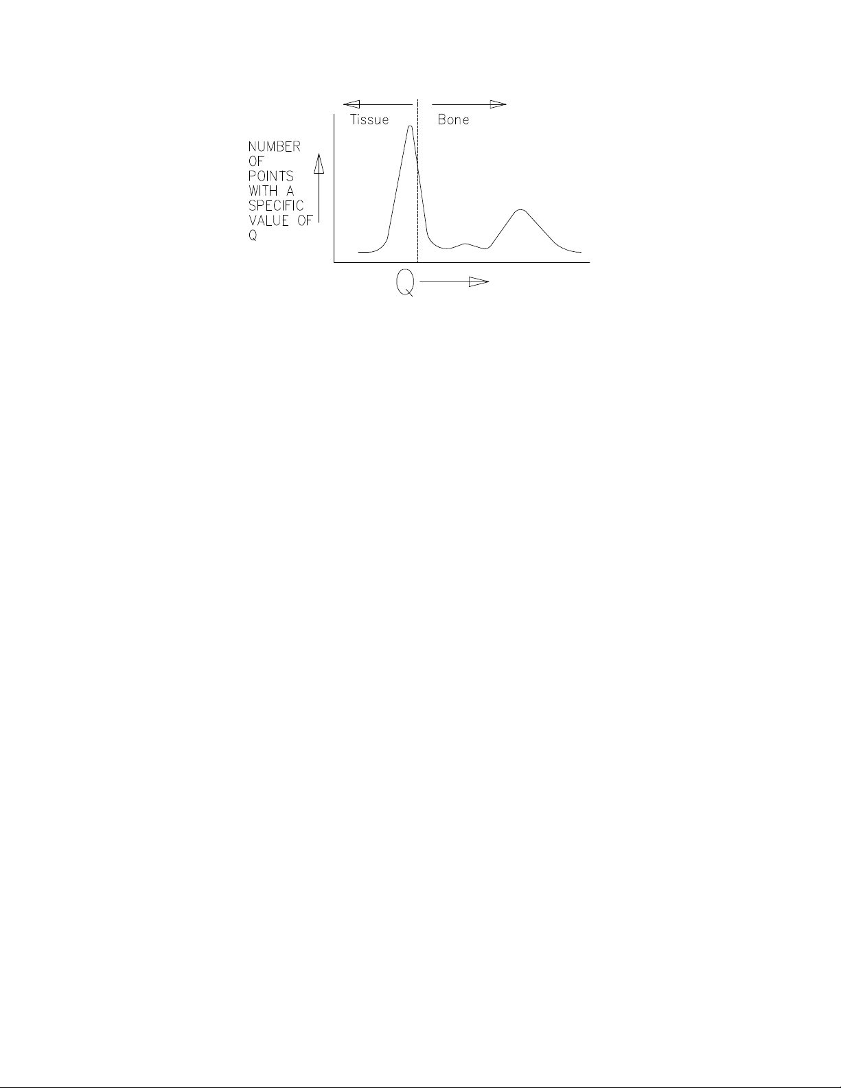
3. Using this value of k, calculate Q for each point scanned using the formula given
above (Q = L - kH). This array of Q values constitutes a "Q scan". Displays the Q
scan.
4. Compile a histogram of the Q values. Because a large portion of the scan con-
tains soft tissue only, this histogram will have a large peak. Choose a threshold
value just above this peak, and apply that value to discriminate, point by point in
the Q scan, between "bone" points (whose Q is above the threshold) and "nonbone" points (whose Q is below the threshold).
1-3
Page 12
Discovery QDR Series Technical Manual
Figure 1-3. Q Scan Plot
5. Use the "non-bone" points to calculate a baseline value for each scan line. Using
these points, form a new histogram and repeat steps 4 and 5 until the results con
verge.
6. Smooth the segment boundaries to eliminate isolated noise-generated "bone"
points.
-
7. Display the "bone" and "non-bone" points for operator approval.
8. Determine the constant of proportionality (d0) that relates the Q values to actual
BMC (grams). This constant is determined by measuring how much Q shifts
when bone-equivalent material is interposed by the filter drum.
9. Calculate the total bone mineral values by adding up the Q values for all "bone"
points in each region of interest (e.g., each vertebra), and multiplying by d0.
10. Determine the bone areas by counting the number of "bone" points in each region
of interest.
11. Calculate bone mineral density as:
BMD = BMC / area
12. Display the calculated results and print the report.
1.2 Functional Overview
This section provides block diagrams of the Discovery system along with a brief
functional overview of each diagram and block. A detailed functional description along
with interconnection diagrams and interconnection descriptions is provided in Section 2 of
this manual.
1-4
Page 13
Discovery QDR Series Technical Manual
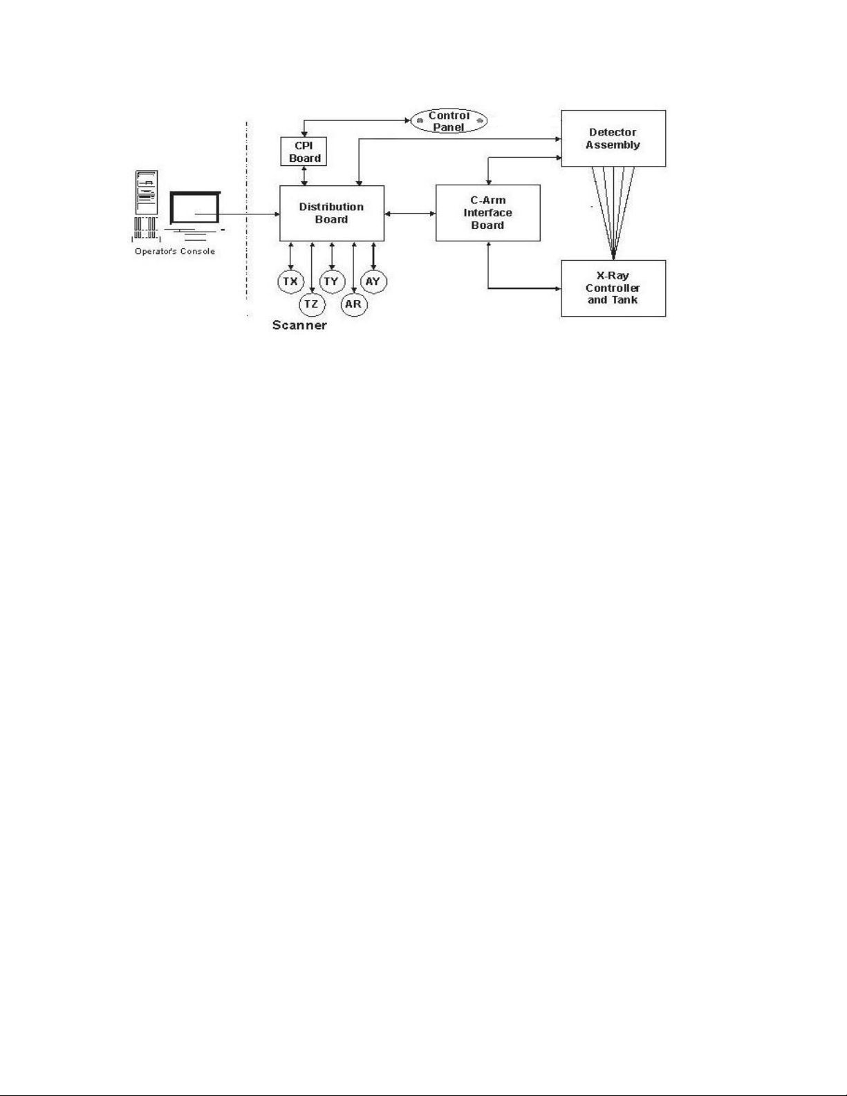
Figure 1-4. Discovery System Block Diagram
The Hologic Discovery consists of essentially three conceptual subsystems. These
subsystems are the Operator’s Console, Motor Control Subsystem, and C-Arm
Subsystem.
The Operator’s Console is the input/output subsystem of the instrument and consists of a
PC running the Discovery system software under Windows XP® and the PCI
Communications Controller Board manufactured by Hologic. The software communicates
with the scanner sending out arm and table motion commands, X-Ray commands, and Xray detection commands. The software also checks to see that commands have been
completed and issues an appropriate error message when a command fails.
The Motor Control subsystem of the scanner is controlled by the Distribution Board. All
motor movement commands are routed through the Distribution Board to the individual
Motor Drivers. There is one Motor Driver for each motor: Arm Y direction (A Y), Table X
direction (TX), T able Y directio n (TY) (A and W models only), and Arm Rotation (AR)(A
and SL models only). The Distribution Board also distributes the DC power throughout
the scanner. Circuit breakers for each Motor Driver can be found on the Distribution
Board.
The C-Arm subsystem controls the generation and detection of X-rays. It processes the
commands received from the Distribution Board and passes them to the X-Ray Controller
or the Detector Assembly. The X-Ray Controller, as its name implies, controls the
generation of the X-Rays by the X-Ray Source or “Tank”. The X-Rays pass through the
patient and are sensed by the Detector Assembly.
1-5
Page 14
Discovery QDR Series Technical Manual
Power
Strip
Keyboard
Mouse
Modem
Network I/F Card
Printer
Monitor
Phone
Jack
AC
AC
AC
Network
Jack
Discovery
Scanner
Video
Computer
AC from
DIN Rail
(Scanner)
AC
PCI
Communications
Controller
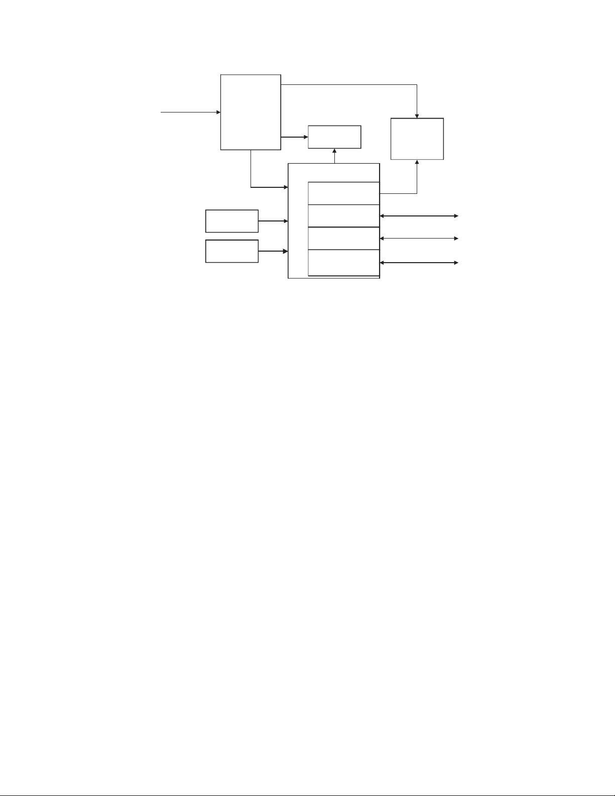
Figure 1-5. Discovery Operator's Console Block Diagram
The Discovery Operator’s Console consists of a Pentium PC on a convenient, roll-around
computer cart designed specifically for the Discovery PC. AC power from the scanner is
fed to the Operator’s Console via a power strip attached to the PC cart.
The Pentium PC contains the video controller board to drive the monitor and the PCI
Communications Controller Board to interface the PC to the Scanner. A modem card is
provided for remote communications with other PCs. A Network Interface Card (NIC) is
installed to control communications with the Hologic QDRNet® or a DICOM® network.
The mouse gives the operator easy control over the Windows XP-based Discovery
software and the keyboard is used for data input to the Discovery software. A color inkjet
printer is provided with the PC. An optional laser printer can be substituted for the inkjet
printer.
1-6
Page 15
Discovery QDR Series Technical Manual
TY Stepper
Motor Driver
TX Stepper
Motor Driver
AY Stepper
Motor Driver
TY
Motor
TY
Encdr
TX
Motor
TX
Encdr
AY
Motor
AY
Encdr
Signal
Distribution
Board
To/From C-Arm Interface
To/From Control Panel Interface
To/From
Communications
Controller
+/-15V
JP1
+24V
From DIN
Rail
and LVPS
AR Stepper
Motor Driver
AR
Motor
AR
Encdr
TZ Stepper
Motor Driver
TZ
Motors
TZ
Encdrs
AC
JP4
JP5
JP7
JP11
JP8
JP6
JP10
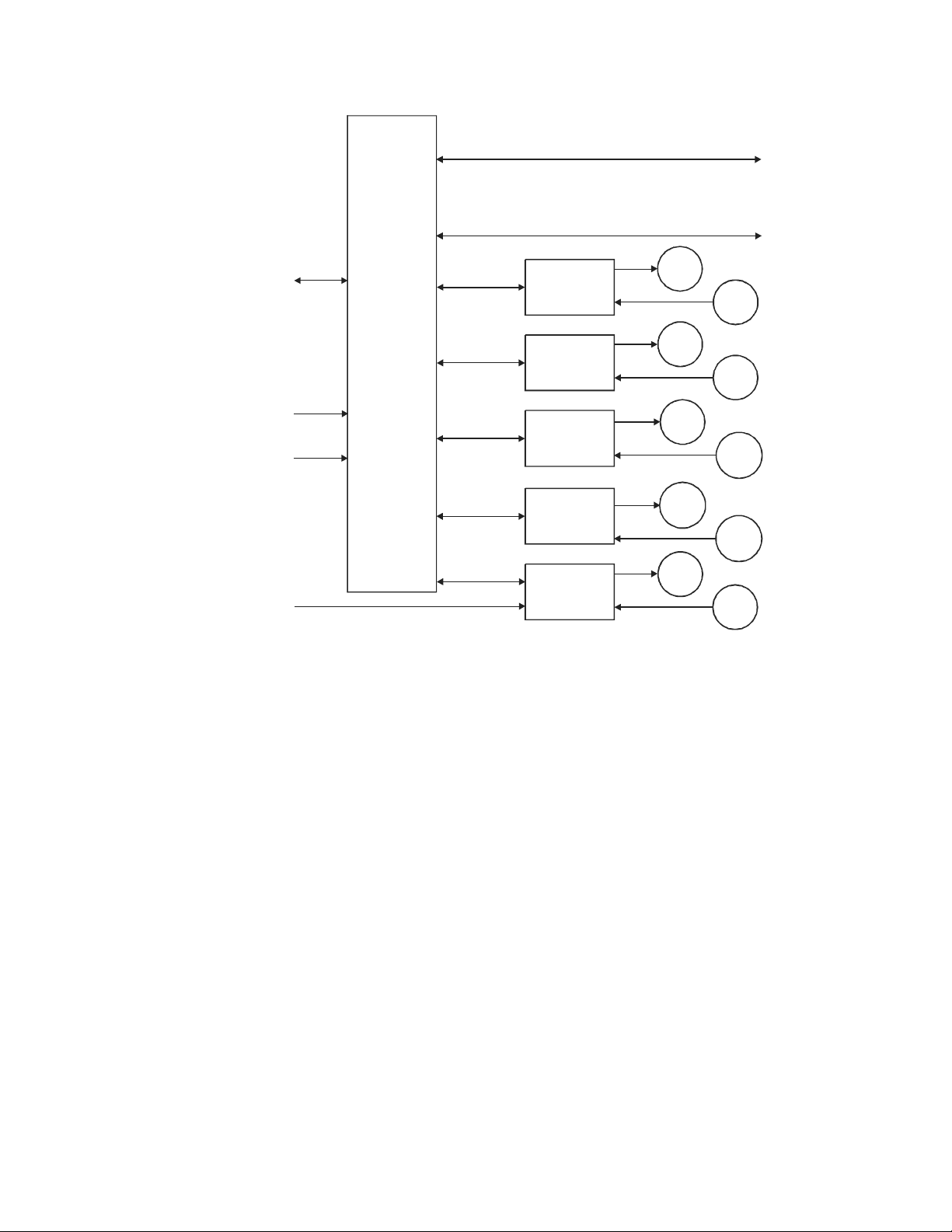
Figure 1-6.Discovery Distribution and Motor Control Block Diagram
The heart of the Discovery Scanner is the Distribution Board. This board interfaces the PC
to the different subsections of the Scanner, distributes control signals to the table and CArm, and distributes DC power throughout the Scanner. The Distribution Board receives
command inputs from the PCI Communications Controller Board in the PC and voltages
from the DIN rail and Low Voltage Power Supply. Commands and voltages dealing with
the generation of X-Rays or the acquisition of scan data are transferred to the C-Arm
Interface Board, which controls both functions. The Distribution Board also receives
Table and C-Arm motion commands from the PCI Communications Controller Board in
the PC.
When a motion command is received, the Distribution Board routes the command along
with a board address to the Motor Driver Boards. The addressed Motor Driver Board
converts these digital commands into analog signals that are strong enough to drive the
motors. A Position Encoder attached to the idler pulley moved by the motor, senses
changes in the position of the arm or table. This device provides a voltage feedback to the
Motor Driver Board that is translated into a motor position, which in turn, is fed back to
software in the Operator’s Console PC.
The Discovery Control Panel is located at the head end of the table and communicates
with the Distribution Board via the Control Panel Interface Board. The Control Panel
provides the operator with a means to issue manual commands to move table and arm
1-7
Page 16
Discovery QDR Series Technical Manual
C-Arm
Interface
Board
Detector Board
(Detectors, Muxes,
and A/D Converter)
Aperture Motor
and
Position Sensor
Filter Drum Motor
and
Position Sensor
Laser
Assembly
Detector Assembly
X-Ray
Controller
X-Ray
Source
(Tank)
To/From
Distribution
Board
From
DIN
Rail
motors, turn power to the instrument on or off, and an indicator showing when X-rays are
being generated.
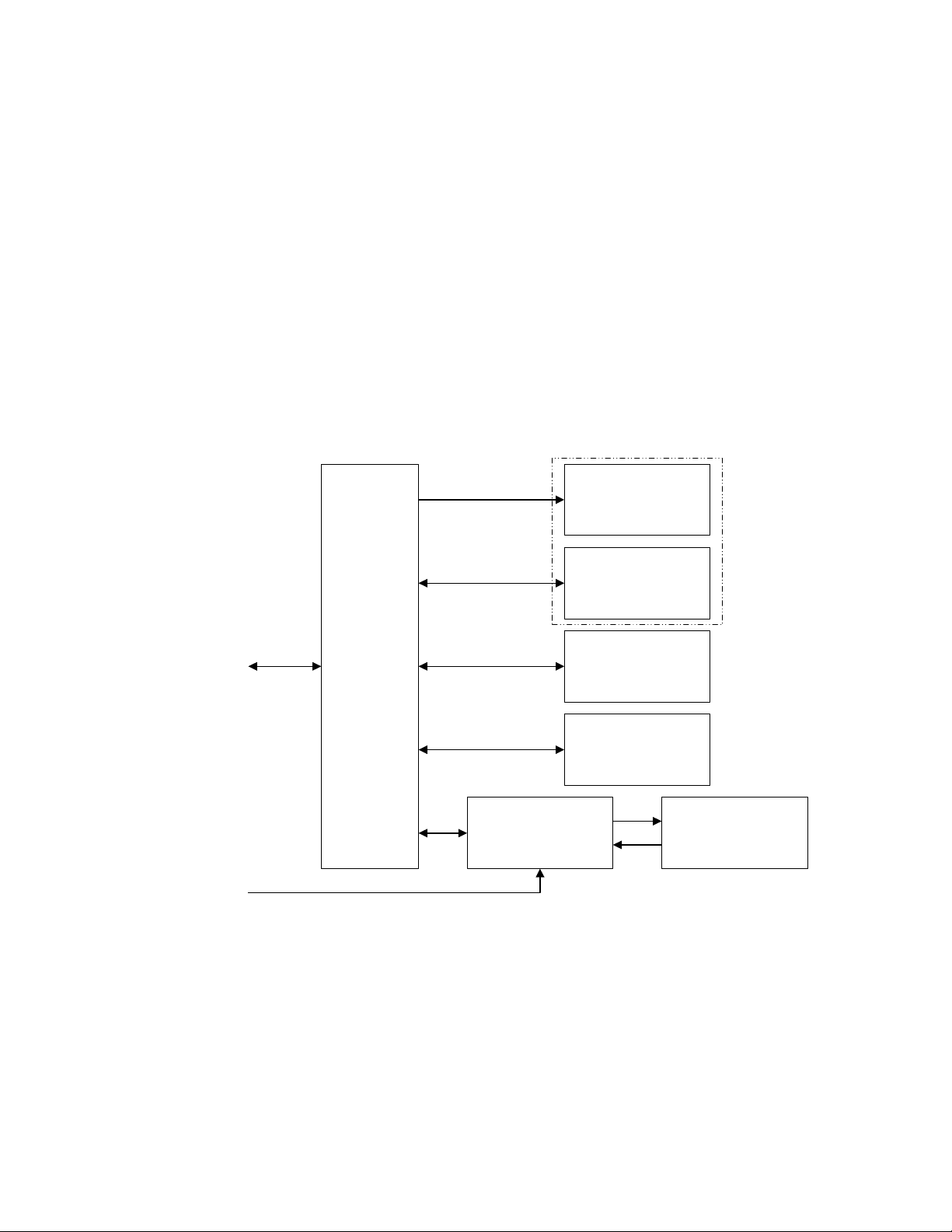
The C-Arm Interface Board controls the C-Arm Subsystem. Commands to the subsystem
arrive from the Distribution Board. The commands processed by the C-Arm Interface
Board are sent to the Positioning Laser, the X-Ray Control ler (XRC ), the Ape rture M otor,
the Detector assembly, or the Filter Drum Assembly. The commands sent to the
Positioning Laser are simple on/of f commands. Commands sent to the XRC tell it when to
produce X-rays, which power level of pulse to produce, and the pulse mode to be used.
These commands will subsequently control the way the X-Ray Source (Tank) is driven by
the XRC. Instructions to the Aperture Motor are for selecting the aperture to be used for
the scan. The commands to the Filter Drum Assembly turn the Filter Drum on or off and
synchronize the filter drum with the AC line waveform. The last set of command signals is
sent to the Detector Assembly to synchronize the acquisition of data with the production
of the X-rays from the source (Tank).
The C-Arm Interface Board collects data from most of the circuits mentioned above for
transmission back to the Distribution Board and, finally, the Discovery software. The
Figure 1-7. Discovery C-Arm Block Diagram
Aperture Motor Assembly sends back position information indicating which of the
aperture slits is in position. The Filter Drum Assembly sends back filter and reference
phase information. The XRC sends back information concerning fault conditions, beam
conditions, and an AC Line signal for generating AC Line Interrupts to the software. The
Detector Board sends data collected from scans back to the software through the C-Arm
1-8
Page 17

Discovery QDR Series Technical Manual
Interface Board and the Distribution Board. Mathematical algorithms applied to this data
produce the scans seen by the operator and to calculate the BMD, BMC, and area of the
bone matter scanned.
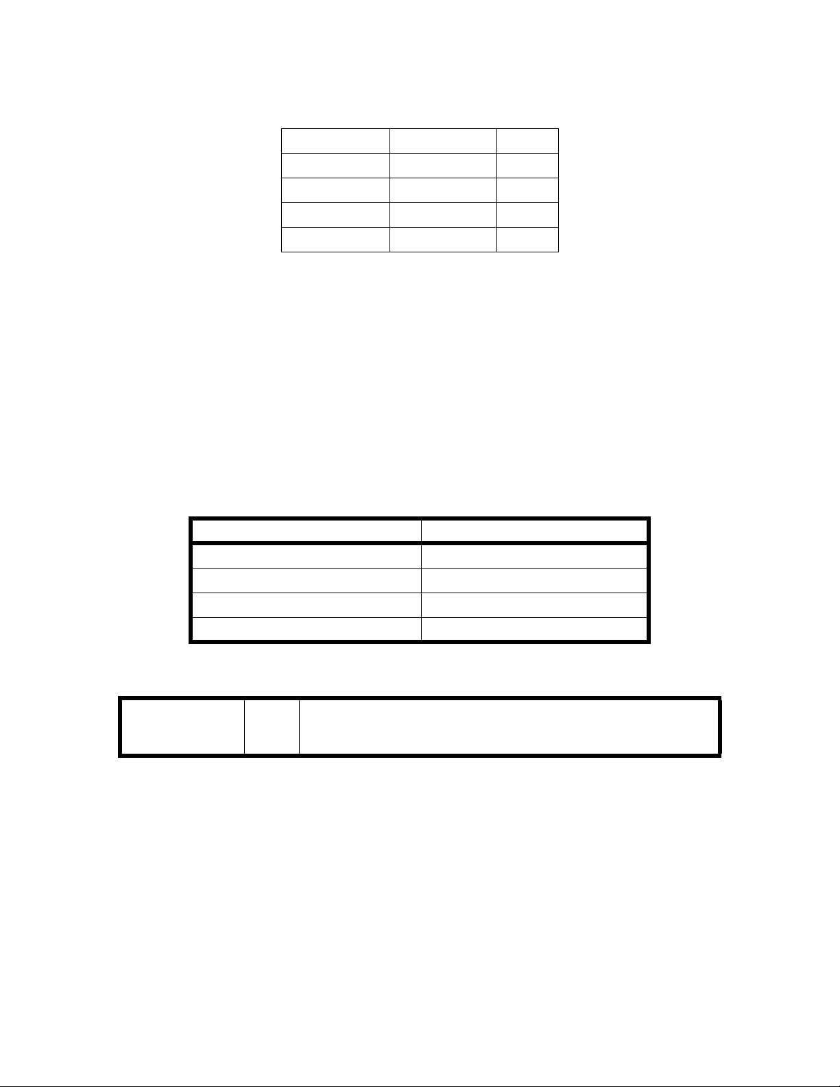
Block Description
Computer Controls and commands all Discovery hardware modules.
PCI Communications
Controller Board
Distributi on Board Provides the interconnections between the Discovery Operator's Console and the
Control Panel Provides switches for manually moving the C-Arm and Patient Table. Also
TX Stepper Motor
Driver
TY Stepper Motor
Driver
TZ Stepper Motor
Driver
AR Stepper M otor
Driver
AY Stepper Motor
Driver
C-Arm Interface Controls the Aperture and Filter Drum motors, generates timing and control signals
X-Ray Controller Controls the operation of the X-ray Source.
Controls the flow of commands to and from the Scanner modules via the
communications bus.
Scanner and distributes DC voltages.
provides Emergency Stop and Instrument On/Off switches.
Controls the motion of the Patient Table in and out motor and monitors table
position information from the encoder.
Controls the motion of the Patient Table left to right motor and monitors table
position information from the encoder (A and W only).
Controls the motion of the Patient Table left and right pedestal motor and monitors
table position information from the string encoders (A and SL only).
Controls the rotational motion of the C-Arm and m onitors C-arm position
information from the encoder (A and SL only).
Controls the motion of the C-Arm left and right motor and monitors C-Arm
position information from the encoder.
for the X-Ray Controller and the Data Acquisition System, monitors the tape
switches, and provides power to the Positioning Laser.
X-Ray Source Unit Generates the X-ray beam.
Detector Board Converts the X-rays into electrical signals. Integrates the signals from the Solid
State Detectors and converts them to a digital value in the Analog-to-Di git a l
converter circuitry.
Control Panel Provides the operator with a means to reposition the table, C-Arm, and to turn on
the laser.
Positioning Laser Provides a laser crosshair beam to assist in positioning the patient on the Patient
Table.
1-9
Page 18

Discovery QDR Series Technical Manual
1.3 Product Specifications
SPECIFICATION MODEL DEFINITION
Scanning Me t hod All Multi-detector array, indexing table, and motorized C-arm
X-ray System All Switched Pulse Dual-Energy X-ray tube, operating at 100 and
140kV, 5mA avg. at 50% duty cycle, 2.5mA avg. at 25% duty
cycle (30sec. maximum), Tungsten target
Detector System A 216 multi-channel detector consisting of CdWO4 scintillators
coupled to silicon diodes
SL/C/ W 128 multi-channel detector consisting of CdWO4 scintillators
coupled to silicon diodes
Scanning Sites A Lumbar spine (in AP and lateral projections), proximal femur
(hip) forearm, IVA Spine, and whole body
SL Lumbar spine (in AP and lateral projections), proximal femur
(hip), IVA Spine, and forearm
W Lumbar spine (in AP and decubitus lateral projections),
proximal femur (hip), forearm, IVA spine (AP only) and whole
body
C Lumbar spine (in AP and decubitus lateral projections),
proximal femur (hip), forearm, and IVA spine (AP only)
Scan Region A 1.95m (76.77 in.) x.65m (25.59 in.) maximum
SL 96cm (38 in.) x .65m (25.59 in.) maximum
W 1.97m (77.5 in.) x.65m (25.59 in.) maximum
C .96m (38 in.) x.51m (20 in.) maximum
Scatter Radiation All Less than 10µGy/h (1mrad/h) at 2m (79 in.) from the center of
the X-ray beam for all scans
Leakage Radiation All The Discovery meets the requirements of 21 CFR 1020.30(k)
for leakage from the X-ray source
External Shielding
Requirement
Calibration All Self Calibrating using Hologic Automatic Internal Reference
All Contact state regulatory agency.
System. Operator calibration NOT required.
1-10
Page 19

Discovery QDR Series Technical Manual
SPECIFICATION MODEL DEFINITION
System Weight
installed
A & SL 327kg 720lb 34.1kg 75lb
C & W 295kg 650lb
System Weight
shipping
Operating
Temperature
Humidity All 20 – 80% relative Humidity, non-condensing
Storage
Temperature
Humidity All 20 – 80% relative Humidity, non-condensing
Footprint Length Width
T ab le extended A & W 3.02 119 1.50
T ab le not exte nded A & W 2.02 79.5 1.22
Average Heat Load ALL 1000w (3400 BTU/hr)
A & SL 659kg 1450lb
C & W 568kg 1250lb
All
All
C & SL 2.02 79.5 1.40
Scanner Console
System
15o – 32o C (59o - 90o F)
15o – 32o C (59o - 90o F)
m inches m
inches m inches
59 1.42 56
48 1.42 56
55 1.42 56
Height
Patient Table
Height
Positioning Laser All Diode laser (<1mW) cross hair, with emergency mechanical shutter
X-Ray Collimation All Dual movable aperture with 0.5mm and 1.0mm slits
Leakage Current All Normal <75µA Single Fault <400µA
Resolution All 0.5 line pair/mm approximately 1.0mm
A & SL Adjustable, 71cm (28 in.) from floor when scanning in AP mode
86.4cm (34 in.) at maximum elevation
C & W 71cm (28 in.) +/- 25mm (1 in.)
1-11
Page 20

Discovery QDR Series Technical Manual
1.3.1 Exam Mode(s) Performance
Exam Type Model Default
Scan
Length (in.)
AP Spine High
Def
AP Spine Array All 8.0 82 L1, L2, L3, L4 0.20 1.0
AP Spine Fast All 8.0 41 L1, L2, L3, L4 0.10 1.0
AP Spine Turbo All 8.0 21 L1, L2, L3, L4 0.05 1.0
Express Scan All 8.0 10 L1, L2, L3, L4 0.07 1.0
Decubitus Lateral
Spine Fast
Lat Spine High
Def
Lat Spine Array A & SL 8.0 240 L1, L2, L3, L4 0.70 1.0
Lat Spine Fast A & SL 6.0 120 L1, L2, L3, L4 0.35 1.0
Hip High Def All 6.0 123 Femur (Total) 0.20 1.0
Hip Array All 6.0 62 Femur (Total) 0.20 1.0
Hip Fast All 6.0 31 Femur (Total) 0.10 1.0
All 8.0 163 L1, L2, L3, L4 0.20 1.0
C & W 8.0 160 L2, L3, L4 0.40 1.0
A & SL 8.0 240 L1, L2, L3, L4 0.35 1.0
D u r a tion(s)
@ Default
Length
Scan Site Dose
mGy
max
in vivo
Precision
(%)
Hip Turbo All 6.0 16 Femur (Total) 0.05 1.0
Dual Hip All 6.0 2X Scan Mode Left & Right
Femur
Whole Body W 77.0 402 Whole Body 0.015 1.0
A 77.0 180 Whole Body 0.01 1.0
Forearm All 6.0 31 Forearm
(Radius &
Ulna) (Total)
IVA SE AP
Imaging
IVA SE R/L
Lateral
IVA DE R/L
Imaging
Small Animal
Spine and Femur
Small Animal
Whole Body
All 16.1 10 Spine T5-L4 0.07 NA
All 16.1 10 Spine T5-L4 0.07 NA
All 13.6 511 Spine T5-L4 0.35 NA
A 2/3 149 Spine & Femur NA NA
A 12.0 122 Whole Body NA NA
Selecte
d Scan
Mode
0.10 1.0
Selected
Scan
Mode
1-12
Page 21
Discovery QDR Series Technical Manual
1.3.2 Duty Cycle:
C, W and SL IVA 12%
All Others 50%
A Whole Body 100%
IVA 12%
All Others 50%
1.3.3 Leakage Technique Factors
The leakage technique factors for all models of Discovery are the same. It is the maximum
continuous current at the maximum peak potential. This is X-ray mode #3. Peak potential
100/140kVp (dual energy), current 10mA peak 25% duty cycle or 2.5mA average.
1.3.4 Minimum Beam Filtration
The minimum filtration permanently in the beam is 3.7mm Al equivalent @80kV.
1.3.5 Measured Half Value Layer (HVL) At Different Operating Potentials
Measured operating potential Measured Half Value Layer
Discovery All
80kV 3.7mm Al equivalent
100kV 5.0mm Al equivalent
140kV 6.5mm Al equivalent
1.3.6 Line Voltage and Maximum Line Current
Power
Requirements:
All 100VAC 16A 50/60Hz, Max apparent resistance = 0.32 ohm
120VAC 14A 50/60Hz, Max apparent resistance = 0.32 ohm
230VAC 8A 50/60Hz, Max apparent resistance = 1.28 ohm
1.3.7 Technique Factors for Maximum Line Current
Peak Potential 140kVp
Tube Current 10mA peak, 50% duty factor or 5mA average.
1-13
Page 22

Discovery QDR Series Technical Manual
1.3.8 Maximum Deviation
The maximum deviation from the preindication given by labeled technique factor control
settings or indicators are as follows:
Peak Potential: +/- 15%
Current: +/- 40%
Time: +/- 10%
1.3.9 Measurement Criteria for Technique Factors
The measurement criteria of the technique factors is as follows:
Peak Potential: The voltage peak is measured with an oscilloscope. Voltage is a squarewave pulse.
Peak is defined as the peak voltage of the 4 millisecond pulse, discounting any initial
overshoot.
Current: Current is measu red with an oscilloscope on the last millisecond of the 4 millisecond
pulse.
Time: Time of each pulse is measured with an oscilloscope and defined as the time between
50% rise and fall times of the peak potential pulse. Time of the scan is measured by
counting the number of AC line pulses from the start to the end. X-ray pulses are
synchronous with the AC line.
1-14
Page 23

Section 2
FUNCTIONAL DESCRIPTION
This section provides a detailed functional description along with interconnection diagrams and
descriptions of the Hologic Discovery. Refer to Section 1 for a block diagram and a brief
functional description of each block.
2.1 Computer
The Discovery Scanner is interfaced to a PCI Communications Controller Board/ISA Bus
computer which controls table and C-arm movement, X-ray generation, performs all necessary
calculations, and manages both the patient and QC database information.
The computer is a Pentium III-based (or higher) PC that comes equipped with floppy disk drive,
hard disk drive, keyboard, mouse, 17” color monitor, and CDROM R/W for archiving scans and
backups of the system database. For details pertaining to the computer and its associated
components, please refer to the documentation shipped with each unit.
2.2 PCI Communications Controller Board
The PCI Communications Controller Board handles all the communications between the
Computer and the Scanner C-Arm and Table assemblies. The board resides in one of the computer
internal ISA slots and communicates with the computer via the computer's I/O bus. It connects to
the Distribution Board in the Scanner through a 50-conductor ribbon cable. This cable contains
two independent communications links (one synchronous and one asynchronous) and additional
system control signals. Each signal requires a pair of conductors for differential (RS422) noise
immunity.
The asynchronous link communicates with the Motor Controller Boards (TX, TY, AR, and AY),
the TZ Drive Board, the C-Arm Interface Board, and the Control Panel Controller section of the
Detector Board (or the Control Panel Interface on A and SL models). The synchronous link
communicates with the Data Acquisition System (DAS).
2.2.1 Interface Connections
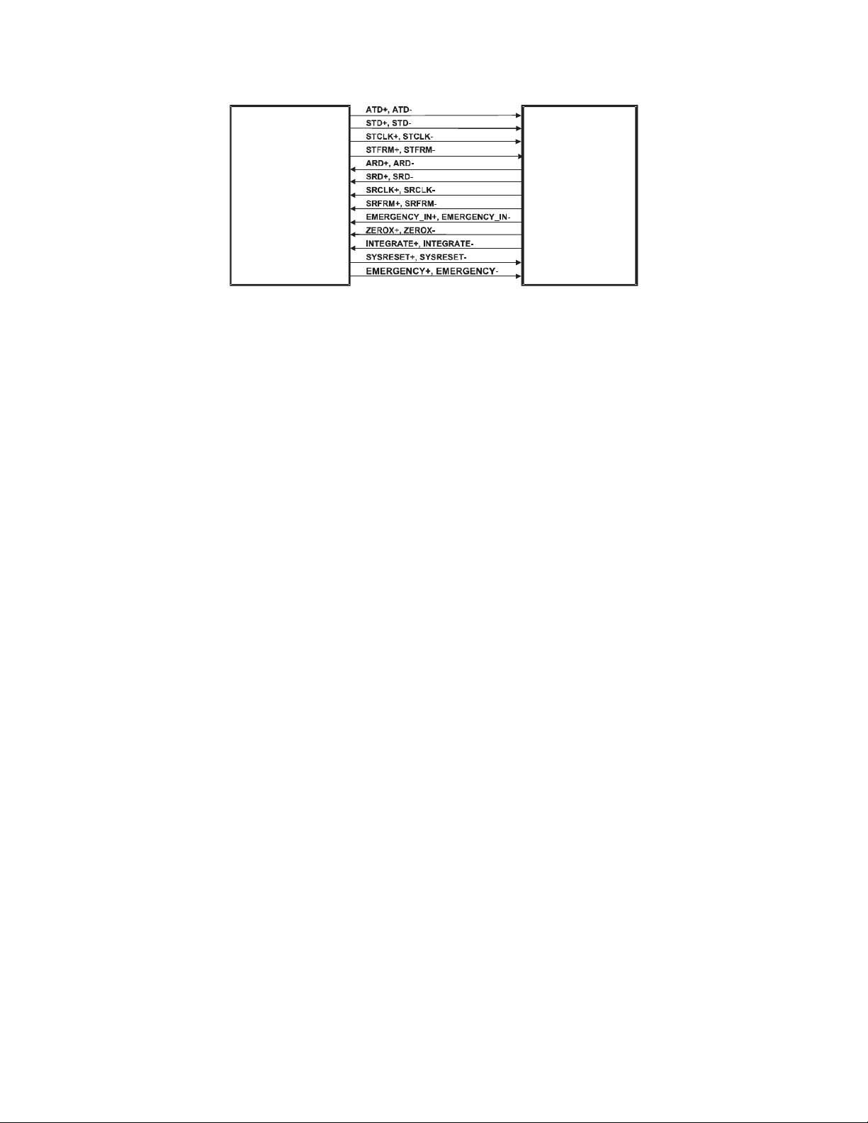
Figure 2-1 on page 2-3 describes the interconnections between the PCI Communications
Controller Board and the Distribution Board. The table also identifies the connectors and their pin
assignments.
2-1
Page 24

Discovery QDR Series Technical Manual
Table 2-1. PCI Communications Controller Board/Distribution Board
Interconnection Descri ptio ns
.
Signal Pair Description
ATD+
ATD-
STD+
STD-
STCLK+
STCLK-
STFRM+
STFRM-
ARD+
ARD-
SRD+
SRD-
SRCLK+
SRCLK-
SRFRM+
SRFRM-
EMERGENCY_IN+
EMERGENCY_IN-
Asynchronous data to the Scanner. JP1-2
Synchronous data to the Scanner. JP1-28
Synchronous data clock from PCI Communications
Controller Board to Distribution Board. Synchronizes
data to the Scanner.
Synchronous data frame from PCI Communication
Command Board to Distribution Board.
Asynchronous Data from the Scanner. JP1-8
Synchronous Data from the Scanner. JP1-34
Synchronous data clock from PCI Communication
Command Board to Distribution Board. Synchronizes
data from the Scanner.
Synchronous data frame from Distribution Board to
PCI Communication Command Board.
Signals an emergency condition. Generated by the CArm Interface Board.
PCI1 Pin Dist2 Pin
JP10-3
JP1-27
JP1-4
JP1-5
JP1-30
JP1-31
JP1-7
JJP1-33
JP1-10
JP1-11
JP1-36
JP1-37
JP1-13
JP1-14
JP1-39
JP10-4
JP10-6
JP10-7
JP10-9
JP10-10
JP10-12
JP10-13
JP10-15
JP10-16
JP10-18
JP10-19
JP10-21
JP10-22
JP10-24
JP10-25
JP10-27
JP10-28
ZEROX+
ZEROX-
INTEGRATE+
INTERGATE-
SYSRESET+
SYSRESET-
EMERGENCY+
EMERGENCY-
AC line zero-crossing signal used for system wide
synchronization. Generated by the C-Arm Interface
Board.
Synchronous signal for Detector Integrate period.
Generated by the C-Arm Interface Board.
Resets the Scanner controllers. JP1-20
Removes power from the Scanner motor drivers and
the X-ray system
Note: 1 PCI = PCI Communication Controller Board
2 Dist = Distribution Board
JP1-40
JP1-16
JP1-17
JP1-42
JP1-45
JP1-49
JP1-25
JP10-30
JP10-31
JP10-33
JP10-34
JP10-39
JP10-40
JP10-48
JP10-49
2-2
Page 25
Discovery QDR Series Technical Manual
KP1085_004-0201
PCI
Communication
Command
Board
DISTRIBUTION
BOARD
Figure 2-1. PCI Communication Command Board/Distribution Board
Interconnection Diagram
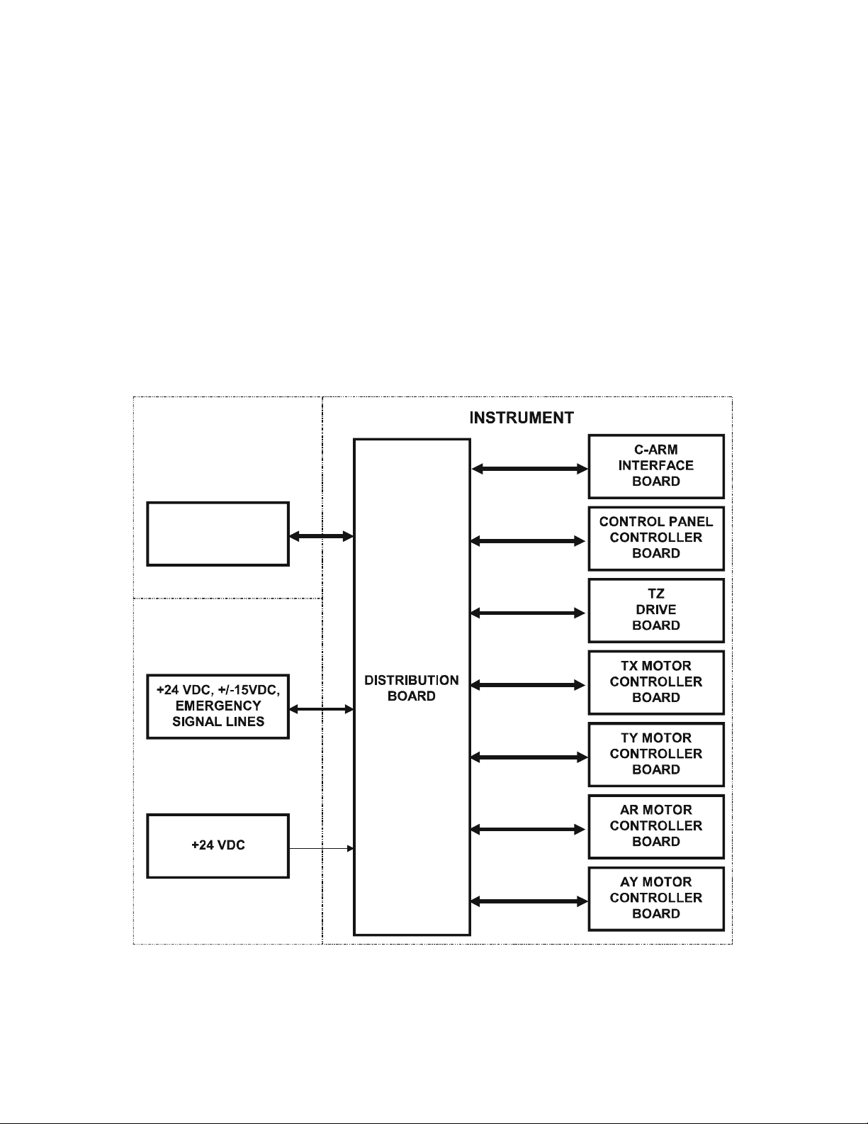
2.3 Distribution Board
The Distribution Board provides interconnections between the Discovery Operator's
Console (PC) and the Scanner. It passes several signal lines from the Operator's Console
and power lines from the DIN rail directly to the C-Arm Interface module. It also provides
buffering and individual drivers and receivers for various signal lines to and from
individual Scanner modules and the PCI Communication Command Board. The
Distribution Board is located in the Electronics Tray in the base of the Scanner.
One cable connects the Operator's Console (PC) communications bus to the Distribution
Board. One cable connects to the Distribution Board from the DIN rail. This cable brings
DC power to the Distribution Board and connects the X-Ray On and Emergency signal
lines to the Power Module.
Up to eight cables connect the Distribution Board to the various Scanner boards
depending on instrument model. Four cables connect to the four Motor Controller Boards
(Table X, Table Y, Arm R, and Arm Y). A single cable connects to the TZ Drive Board.
T wo cables (one signal and one power) connect to the C-Arm Interface Board. In addition,
one cable connects to the scanner Control Panel Interface Board. In the C and W models,
this board is a separate section of the Detector Board. In the A and SL versions, the
Control Panel Interface Board is a separate board located under the table.
The Distribution Board has provision for three jumpers that can be installed to override
the EMERGENCY signal lines when troubleshooting.
2.3.1 Power
The Distribution Board receives +24 and +/-15VDC from the Multi-voltage DC Switching
Power Module. The +24VDC is applied through four individual circuit breakers to the
Table X, Table Y, Arm R, and Arm Y Motor Controller Boards. The +24 and +/-15VDC
are passed to the C-Arm Interface Board. The +24 VDC is also reduced to +7 and +5VDC
by regulators to power op-amps and analog switches located on this board. The +7VDC is
passed to the Control Panel Controller Board. The +5VDC powers the digital section of
2-3
Page 26
Discovery QDR Series Technical Manual
COMMUNICATIONS
CONTROLLER
BOARD
OPERATOR’S
CONSOLE
COMPUTER
INSTRUMENT
ELECTRONICS
TRAY
the Distribution Board. The +24VDC power supply is not closely regulated and its outputs
may range from +24V to +35V under normal conditions.
Note: +7VDC may measure anywhere from +6.25VDC to +7.25VDC. This is true
everywhere +7VDC is shown in this manual.
Limits for +/- 15VDC
Six green LEDs indicate the status of the +28 (on QDR-4500s, +24 on Discovery), +24,
+15, -15, +7 and +5VDC (ON indicates the respective voltage is present). Five red LEDs
indicate the status of the five circuit breakers applying voltage to the motor drivers/
controller. ON indicates the circuit breaker has been tripped by an over-current condition.
2.3.2 Interface Connections
Figure 2-2 shows connections to/from the Distribution Board.
Figure 2-2. Distribution Board High Level Interconnection Diagram
2-4
Page 27

Discovery QDR Series Technical Manual
2.4 Motor Controller Boar d
The Motor Controller Board is a microprocessor controlled power driver circuit for use
with a two-coil bipolar stepper motor. It receives high-level commands through the
Distribution Board from the host computer, and applies 24-volt pulses to the stepper motor
windings. The Discovery uses four identical Motor Controller Boards to control and drive
the Table X (Table In/Out), Table Y (Table Left/Right), C-Arm Y (C-Arm Left/Right), CArm R (Arm rotation, A/SL only) stepper motors. The motor windings are driven by two
integrated H-bridges. These integrated circuits provide internal level conversion and
power limiting. Their logic level control inputs are driven from a stepper motor control
microcircuit that receives commands from the microprocessor. The control circuit senses
the current in the motor windings and adjusts the duty cycle of the applied voltage in such
a way as to limit the maximum motor current. The maximum value is determined by an 8bit control word at a Digital to Analog Converter.
Each Motor Controller Board monitors the position of its respective mechanism using a
voltage received from an associated Position Encoder connected to the mechanism. The
Position Encoder is a precision potentiometer that divides a +/-3V reference source. The
output voltage is fed to a sense amplifier in proportion to the position of the mechanism
driven by the motor. The sense amplifier output is converted to digital value that provides
position feedback to the microprocessor.
The Motor Controller Boards receive movement commands from the Discovery computer
via the communications bus. Each Motor Controller Board contains an ID switch and four
status indicators (LEDs). The ID switch is a 16-position rotary encoded switch (SW1) that
is read during system initialization to determine the Motor Controller Board address for
communicating with the Discovery computer. ID switch settings for the Motor Controller
Boards are as follows:
Table X drive 4
Table Y drive 5
C-Arm Rotation 6
C-Arm Y drive 7
The four red status LEDs provide visual indications of motor drive power on, Stepper
CPU active, motor drive direction, and motor step pulses.
The Motor Controller Board also has provision (JP2) for connecting limit switches to
inhibit motor operation when the mechanism goes beyond established mechanical limits.
This feature is not used in the Discovery and, therefore, no cable is connected to JP2.
2.4.1 Power
Power input to the Motor Controller Board is +24VDC. This voltage provides the motor
drive power and is converted down to +5VDC for use by logic circuits on the board. The
+5VDC is also converted to -5VDC. Two green LEDs provide a visual indication of the
power present on the Motor Controller Board.
2-5
Page 28
Discovery QDR Series Technical Manual
ARD+, ARDATD+, ATDSYSRESET+, SYSRESET+28V
28V_RET
(⎯)
(⎯)
(⎯)
(⎯)
+REF
(⎯)
-REF
MOTOR
CONTROLLER
STEPPER
MOTOR
To/From
Distribution Board
POSITION
ENCODER
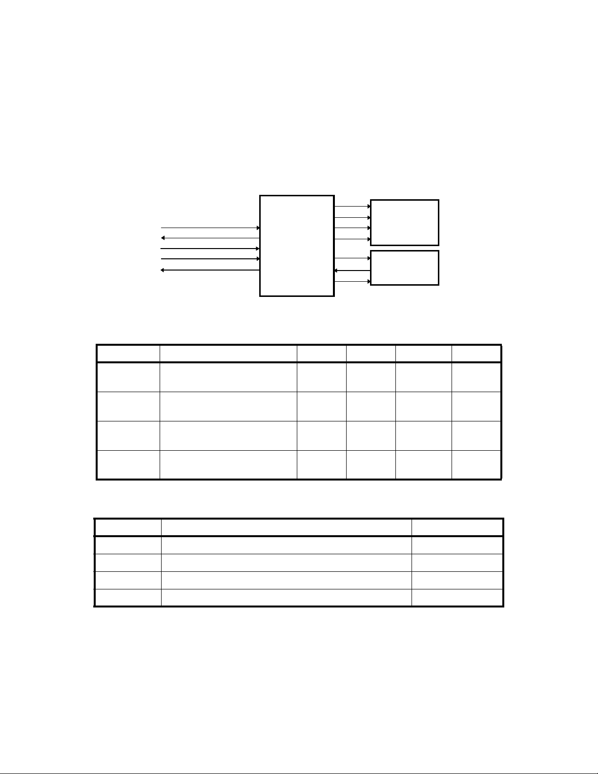
2.4.2 Interface Connections
Figure 2-3 shows the typical interconnections between the Distribution Board, the Motor
Controller Board, the Stepper Motor, and the Position Encoder. Figure 2-1 describes the
interconnections between the Distribution Board and the Motor Controller. Table 2-3
describes the interconnections between each Motor Controller and its respective stepper
motor and position encoder. The tables also identify the connectors and their pin
assignments.
Figure 2-3. Distribution Board/Motor Controller Board Interconnection Diagram
Table 2-2.Distribution Board/Motor Controller Board Interconnection Descriptions
Signal Description Table X Table Y C-Arm Y Pin(s)
ARD+
ARD-
ATD+
ATD-
SYSRST+
SYSRST-
28V
28V_RET
Asynchronous Receive Data. JP7 JP5 JP11 11
12
Asynchronous Transmit Data. JP7 JP5 JP11 14
15
System Reset. Resets the Motor
Controller Board.
DC power for the Motor
Controller Board.
JP7 JP5 JP11 17
18
JP7 JP5 JP11 2,3,4,5
1,6,7,8
Table 2-3. Motor Controller Board/Stepper Motor and Position Encoder
Interconnection Descriptions
Signal Description Pin
(No label) Motor drive signals (4). JP5-1 - JP5-4
+REF (+3V) Precision posit ive v oltage to position potentiometer. JP3-1
(No label) Position encoder wiper return voltage. JP3-3
-REF (-3V) Precision negative voltage to position poten tiome ter. JP3-5
2.5 TZ Drive Board (A and SL Only)
The TZ Drive Board is a microprocessor-controlled power driver circuit for the two AC
pedestal motors, which raise and lower the patient table of the Discovery A and SL. This
2-6
Page 29

Discovery QDR Series Technical Manual
board is located in the Electronics Tray in the rear of the bottom of the Scanner base
assembly.
The TZ Drive Board communicates with the PCI Board, via the Distribution Board, to
drive the pedestal motors under computer control. Manual repositioning of the pedestal
may be required in case of an emergency . In this case, manual control is provided through
the Table switches of the Scanner’s Operator Control Panel.
The TZ Drive board monitors the position of both pedestals using signals received from an
associated Position Encoder connected to the respective pedestal.
2.5.1 Service Switches
The TZ Drive board contains four service switches used during replacement of a defective
pedestal or Position Encoder. Table 2-4 describes these switches and their respective
functions.
Caution: The TZ drive motors are designed to run at a 5% duty cycle. If the motors
overheat, the built-in thermal cutouts may trip and cause the motors to stop
functioning. If this occurs, you must wait about 20 minutes before
functionality is restored.
The TZ drive motors are designed to run at a 5% duty cycle. If the motors overheat, the
built-in thermal cutouts may trip and cause the motors to stop functioning. If this occurs,
you must wait about 20 minutes before functionality is restored.
Table 2-4.TZ Drive Service Switches
Switch Function
Mode (Normal/Service) Determines whether the TZ Drive is in Normal or Service
operation.
Direction (Up/Down) When the TZ drive is in Service mode, determines the
direction of pedestal movement (not active in normal
mode).
Left When the TZ drive is in Service mode, moves the left
pedestal in the direction specified by the Direction switch
(not active in normal mode).
Right When the TZ drive is in Service mode, moves the right
pedestal in the direction specified by the Direction switch
(not active in normal mode).
Reset Resets the board after manual operation. The TZ Drive
board must be reset after any manual operation.
2.5.2 Power
Power input to the TZ Drive Board is +24VDC from the Distribution Board and 240VAC
from the DIN Rail. The +24VDC powers circuitry located on this board and is reduced to
2-7
Page 30
Discovery QDR Series Technical Manual
ARD+, ARD-
ATD+ , ATDSYSRESET+,
EMERGENCY+,
MAN_UP*, MAN_UP_RET
MAN_DOWN*, MAN_DOWN_RET
+24V
120V(A)_UP_LEFT
120V(A)_DWN_LEFT
120V(B)_LEFT
GND_PED
+3.0VREF
(Position Signal)
-3.0VREF
120V(A)_UP_RIGHT
120V(A)_DWN_RIGHT
120V(B)_RIGHT
GND_PED
+3.0VREF
(Position Signal)
-3.0VREF
TZ
DRIVE
BOARD
LEFT
PEDESTA L
MOTOR
To/From
Distribution Board
To/From
DIN Rail
Assembly
LEFT
PEDESTAL
POSITION
ENCODER
RIGHT
PEDESTAL
MOTOR
RIGHT
PEDESTAL
POSITION
ENCODER
120V(A)_RIGHT
120V(B)_RIGHT
GND_PED
120V(A)_LEFT
120V(B)_LEFT
GND_PED
+5VDC. The +5VDC is converted to -5VDC and +/-3VDC. The +/-5VDC powers logic
circuitry on this board, while the +/- 3VDC provides the reference voltage for the position
sensors. Two green LEDs provide visual indication of the +24 and +5VDC status (ON
indicates the respective voltage is present).
The 240VAC power is connected through control relays to the pedestal motors.
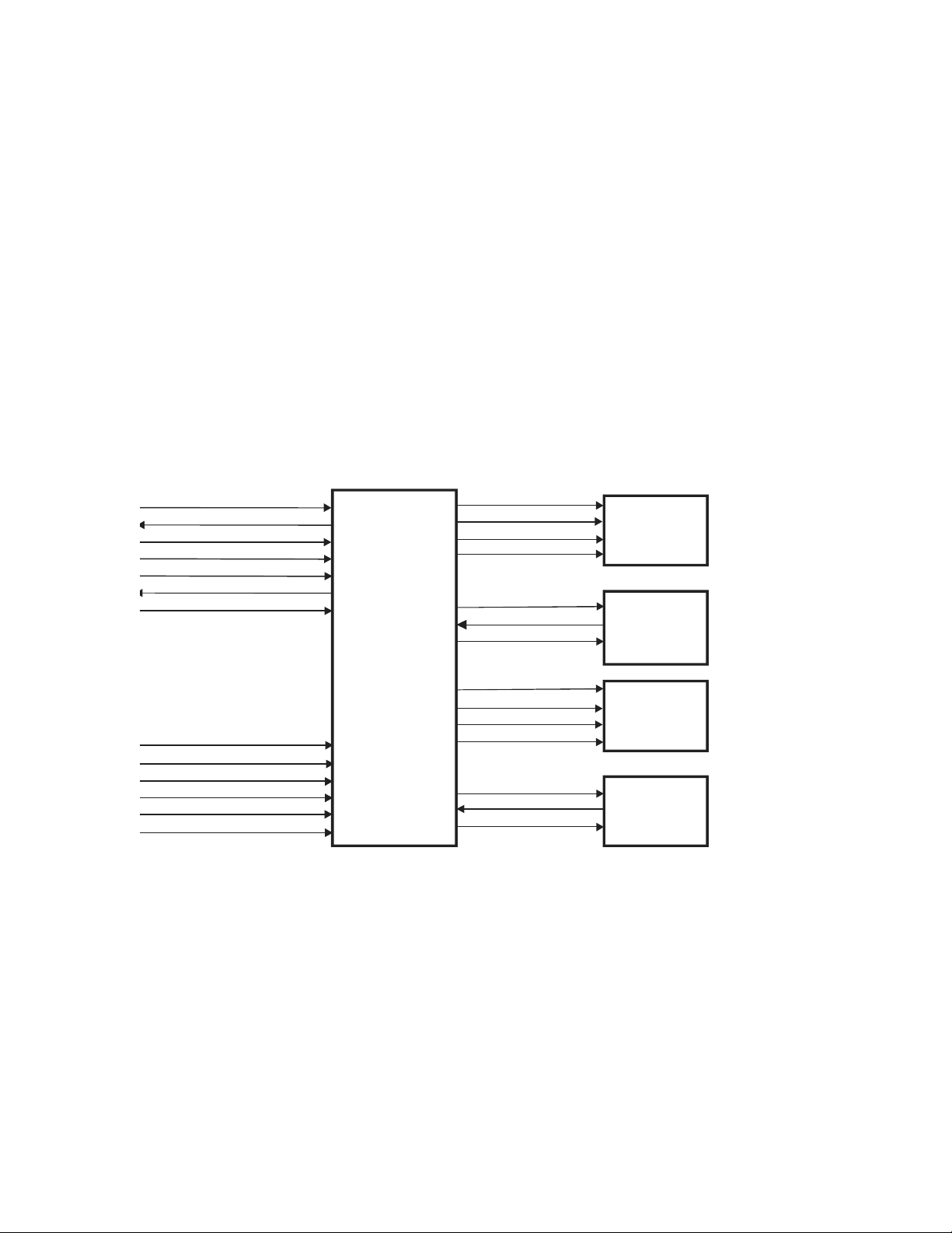
2.5.3 Interface Connections
Figure 2-4 shows the interconnections between the Distribution Board, the TZ Drive
Board, the Pedestal Motors, and the Pedestal Position Encoders. Table 2-5 describes the
interconnections between the Distribution Board and the TZ Drive Board. Table 2-6
describes the line voltage (240VAC, line to line) between the DIN Rail Assembly and the
TZ Drive Board. Table 2-7 describes the interconnections between the TZ Drive Board
and the two pedestal motors and their respective position encoders. The tables also
identify the interconnection connector and pin assignments.
Table 2-4 shows the interconnections between the Distribution Board, the TZ Drive
Board, the Pedestal Motors, and the Pedestal Position Encoder, Table 2-5 describes the
interconnections between the Distribution Board and the TZ Drive Board. Table 2-6
describes the line voltage (240VAC line to line) between the DIN Rail Assembly and the
TZ Drive Board. Table 2-7 describes the interconnection between the TZ Drive Board and
the two pedestal motors and their respective position encode rs. The tabl es also iden tify the
interconnection connectors and pin assignments.
2-8
Figure 2-4. Distribution Board/TZ Drive Board Interconnection Diagram
Page 31

Discovery QDR Series Technical Manual
Table 2-5. Distribution Board/TZ Drive Board Interconnection Descriptions
Signal Description Pin(s)
ARD+
ARD-
ATD+
ATD-
SYSRST+
SYSRST-
EMERGENCY+
EMERGENCY-
MAN_UP*
MAN_UP_RET
MAN_DWN*
MAN_DWN_RET
+24V DC power for the Motor Controller board. JP1-5, JP1-6
+6.5V Not used. JP1-2, JP1-3
Asynchronous Receive Data. JP1-11
JP1-12
Asynchronous Transmit Data. JP1-14
JP1-15
System Reset. Resets the TZ Drive board. JP1-17
JP1-18
Enables manual operation of the pedestals in the case
of an emergency (under control of the Control Panel
Table switch on the Patient Table).
Raises the Patient Table in the case of an emergency. JP1-23
Lowers the Patient Table in the case of an emergency. JP1-26
JP1-20
JP1-21
JP1-24
JP1-27
Table 2-6. DIN Rail Assembly/TZ Drive Board Interface Descriptions
Signal Description Pin
120V(A)_LEFT AC voltage (120) to drive the Left Pedestal motor. JP6-4
120V(B)_LEFT AC voltage (120) to drive the Left Pedestal motor. JP6-5
120V(A)_RIGHT AC voltage (120) to drive the Right Pedestal motor. JP6-1
120V(B)_RIGHT AC voltag e (12 0) to driv e the R ig ht Pede stal motor. JP6-2
GND_PED Ground line to the Left/Right Pedestal motor. JP6-3/JP6-
6
Table 2-7. TZ Drive Board/Pedestal Motors and Position Encoders
Interconnection Descriptions
Signal Description Pin
120V(A)_UP_LEFT AC v ol tage to th e Left Pedestal motor to move the left
end of the Patient Table up.
120V(A)_DWN_LEFT AC voltage to the Left Pedestal motor to move the left
end of the Patient Table down.
120V(B)_LEFT AC line to the Left Pedestal m otor. JP5-3
GND_PED Ground line to the Left Pedestal motor. JP5-4
120V(A)_UP_RIGHT AC voltage to the Right Pedestal motor to move the
right end of the Patient Table up.
120V(A)_DWN_RIGHT AC voltage to the Right Pedestal motor to mo ve the
right end of the Patient Table down.
120V(B)_RIGHT AC line to the Right Pedestal motor. JP4-3
GND_PED Ground line to the Ri gh t Pedestal motor. JP4-4
JP5-1
JP5-2
JP4-1
JP4-2
2-9
Page 32

Discovery QDR Series Technical Manual
Signal Description Pin
+3.0VREF Precision positive voltage to Left/Right Pedestal
position encoder potentiometer.
(Position Signal) Left/Right pedestal position encoder wiper return
voltage.
-3.0VREF Precision negative voltage to Left/Right Pedestal
position encoder potentiometer.
JP3-1/JP2-1
JP3-3/JP2-3
JP3-4/JP2-4
2.6 Control Panel Controller Board
The Control Panel Controller Board on the Discovery is a separate board under the table.
Its function is to interface the Scanner Operator Control Panel to the computer allowing
the software to determine the state of the Operator Control Panel switches, to define the
state of the various Operator Control Panel LEDs, and to control motor movement. The
board is located under the table at the head end of the scanner.
The Control Panel Controller communicates with the Operator's Console computer using
the asynchronous communications signals ARD and ATD of the communications buss and
the system control signals SYSRESET, XRAY_LIGHT, and EMERGENCY.
2.6.1 Power
The Control Panel Controller Board receives +7VDC from the Distribution Board. The +7
is reduced to +5VDC to power the circuitry on this board and is applied to the Operator
Control Panel to power the LEDs. A green LED, on this board, provides a visual
indication of the +5VDC power (ON indicates the voltage is present).
2.6.2 Interface Connections
Figure 2-5 shows the interconnections between the Distribution Board, Control Panel
Controller Board, and the Operator Control Panel.
Table 2-8 describes the interconnections between the Distribution Board and the Control
Panel Controller. Table 2-10 describes the interconnections between the Control Panel
Controller and the Operator Control Panel. The tables also identify the connectors and
their pin assignments.
2-10
Page 33

Discovery QDR Series Technical Manual
ARD+, ARDATD+, ATD-
SYSRES ET+, SYSRESETEMERGEN CY+, EMERGE NCY-
XRAY_LIGHT+, XRAY_LIGHTMAN_TZ_UP
MAN_TZ_UP_RET
MAN_TZ_DOWN
MAN_TZ_DOWN_RET
EMERBENCY_PANEL
HW_EMERGENCY_RET
+7V
L0_PWR* - L7_PWR*
TZ_PWR*
XRAY_LIGHT_PWR*
SW0 - SW2
SR0 - SR2
MAN_TZ_UP
MAN_TZ_UP_RET
MAN_TZ_DOWN
MAN_TZ_DOWN_RET
EMERGENCY_PANEL
HW_EMERGENCY_RET
+5V
CONTROL
PANEL
CONTROLLER
OPERATOR
CONTROL
PANEL
To/From
Distribution Board
TILT_A
TILT_B
To/From
C-Arm
Tilt Switch
(A/SL)
Table 2-8. Distribution Board/Control Panel Controller Interconnection Descriptions
Signal Description Pin
ARD+
ARD-
ATD+
ATD-
SYSRESET+
SYSRESET-
EMERGENCY+
EMERGENCY-
XRAY_LIGHT+
XRAY_LIGHT-
EMERGENCY_CPANEL
HW_EMERGENCY_RET
+7V DC power for the Control Panel Controller
Figure 2-5. Control Panel Controller Interconnection Diagram
Asynchronous Receive Data from the PCI
Communication Command Board via the
Distribution Board.
Asynchronous Transmit Data to the PCI
Communication Command Board via the
Distribution Board
System Reset from the PCI Communication
Command Board via the Distribution Board.
Resets the Control Panel Controller.
Emergency TZ drive indicator from the PCI
Communication Command Board via the
Distribution Board.
X-Ray Light from the X-Ray Controller via
the C-Arm Interface and Distribution Boards.
State of the STOP switch and of the collision sensor.
(Part of the safety daisy chain.)
Board
JP2-4
JP2-5
JP2-7
JP2-8
JP2-10
JP2-11
JP2-13
JP2-14
JP2-16
JP2-17
JP2-19
JP2-20
JP2-2
2-11
Page 34

Discovery QDR Series Technical Manual
Table 2-9. Control Panel Controller/Control Panel Interconnection Descriptions
Signal Description
L0_PWR* Turns on the ENABLE switch LED. JP6-11 JP1-11
L1_PWR* Turns on the HOME switch LED. JP6-12 JP1-12
L2_PWR* Turns on the LOAD switch LED. JP6-13 JP1-13
L3_PWR* Turns on the TABLE switch IN/OUT LED. JP6-14 JP1-14
L4_PWR* Not used. JP6-15 JP1-15
L5_PWR* Turns on the C-ARM switch RIGHT/LEFT
LED.
L6_PWR* Not used. JP6-17 JP1-17
L7_PWR* Turns on the Laser LED. JP6-18 JP1-18
XRAY_LIGHT_PWR* Turns on the X_RAY LED JP6-19 JP1-19
SW0 Control signal to determine the state of the
C-ARM and LASER switches.
SW1 Control signal to determine the state of the
TABLE IN/OUT switches.
SW2 Control signal to determine the state of the
LOAD, HOME and ENABLE switches.
SR0 Returns the state of the C-ARM switch LEFT
position when SW0 is active. Signals the
state of the TABLE switch IN position when
SW1 is active. Signals the state of the LOAD
switch when SW2 is active.
SR1 Returns the state of the C-ARM switch
RIGHT position when SW0 is active. Signals
the state of the TABLE switch OUT position
when SW1 is active. Signals the state of the
HOME switch when SW2 is active.
SR2 Returns the state of the LASER and
ENABLE switches when SW2 is active.
EMERGENCY_CPANEL
HW_EMERGENCY_RET
+5V Provides power for the Control Panel LEDs. JP6-21
Returns the state of the STOP switch. (Part of
the safety daisy chain.)
1
CPC
Pin
JP6-16 JP1-16
JP6-4 JP1-4
JP6-5 JP1-5
JP6-6 JP1-6
JP6-1 JP1-1
JP6-2 JP1-2
JP6-3 JP1-3
JP6-23
JP6-24
JP6-22
2
CP
Pin
JP1-23
JP1-24
JP1-21
JP1-22
Note: 1 CPC = Contr ol Panel Controller
2 CP = Control Panel
2.7 C-Arm Interfac e Boa rd
The C-Arm Interface Board distributes DC power and signals to the Data Acquisition
System (DAS) and provides control electronics for the devices located in the C-Arm
assembly. It passes several signal and power lines from the Distribution Board directly to
2-12
Page 35

Discovery QDR Series Technical Manual
the DAS. It also provides buffering for various signal lines. The C-Arm Interface Board is
located near the rear of the lower C-Arm’s horizontal shelf.
Note: On the Discovery A model, the Data Acquisition System (DAS) consists of the
Analog to Digital Converter, Integrator/Multiplexor, and Solid State Detector
Boards. On the Discovery SL, C, and W models, a single-board, 128-Channel
Detector Assembly is used.
The C-Arm Interface provides circuitry to:
• Control and monitor operation of the X-ray Controller Board. Four LEDs (two red,
one green, and one yellow) on this board, provide a visual indication of the status
of the X-Ray Controller and the X-ray control circuitry of this board.
• Generate timing references to the DAS and PCI Communication Command Board.
• Control power to the Positioning Laser.
• Move the Aperture stepper motor and monitor its mechanically linked positionsensing device.
• Move the stepper motor of the Reference Drum device and monitor the encoded
signals returned from each drum of the device. Two green LEDs, on this board,
provide a visual indication of the Reference Drum operation.
• Generate +7VDC for the DAS system
2.7.1 Continuity Daisy Chain
The C-Arm Interface Board is part of two linked chains of boards. Removing any of these
boards conveys an alarm message to the host computer indicating that the electrical
integrity of the system has been compromised. This message can be decoded by the host
computer to detect the extent of the damage.
2.7.2 Power
The C-Arm Interface Board receives +24 and +/-15VDC from the Distribution Board. The
+24VDC powers the Aperture and Reference Drum stepper motor driver circuitry. The +/15V is passed through this board to the DAS. The +24VDC is also reduced to +5 and
+7VDC. The +5VDC powers the digital section of this board and the laser while the
+7VDC is applied to the DAS.
Three green LEDs, on this board, provide a visual indication of the +24 and +5VDC
power (ON indicates the respective voltage is present). The third LED monitors the
+28VDC used on the QDR-4500 models. On the Discovery, this voltage is actually
+24VDC.
2.7.3 Interface Connections
Figure 2-6 shows the interconnections between the Distribution Board and the C-Arm
Interface Board. Table 2-10 describes the interface signals and identifies the connectors
and their pin assignments.
2-13
Page 36

Discovery QDR Series Technical Manual
ATD_CARM+, ATD_CARMSTD+, STDSTCLK+, STCLKSTFRM+, STFRMARD_CARM+, ARD_CARMSRD+, SRDSRCLK+, SRCLKSRFRM+, SRFRMEMERGENCY_CARM, EMERGENCY_CPANEL
LINESYNC+, LINESYNCINTEGRATE+, INTEGRATESYSRST_CARM+, SYSRST_CARMEMERGENCY+, EMERGENCYXRAY_LIGHT+, XRAY_LIGHT-
+15V
15V_RET
-15V
24V
24V_RET
28V
28V_RET
C-ARM
INTERFACE
BOARD
DISTRIBUTION
BOARD
CONTINUITY 1
CONTINUITY 2
Figure 2-6. Distribution Board/C-Arm Interface Board
Table 2-10. Distribution Board/C-Arm Interface Board Interconnection Descriptions
Signal Des cription
ARD_CARM+
ARD_CARM-
STD+
STD-
STCLK+
STCLK-
STFRM+
STFRM-
ATD_CARM+
ATD_CARM-
SRD+
SRD-
Asynchronous data to the C-Arm Interface Board. JP1-3
Synchronous data through the C-Arm Interface
Board to the DAS.
Synchronizes data through the C-Arm Interface
Board to the DAS.
Synchronous channel data frame from PCI Board
through the Distribution Board to the DAS.
Asynchronous Data from the from the C-Arm
Interface Board.
Synchronous Data through the C-Arm Interface
Board from the DAS.
2-14
Interconnection Diagram
1
Dist
Pin
JP1-4
JP1-6
JP1-7
JP1-9
JP1-10
JP1-12
JP1-13
JP1-15
JP1-16
JP1-18
JP1-19
C-ARM
Pin
JP1-3
JP1-4
JP1-6
JP1-7
JP1-9
JP1-10
JP1-12
JP1-13
JP1-15
JP1-16
JP1-18
JP1-19
2
Page 37

Discovery QDR Series Technical Manual
Signal Description
SRCLK+
SRCLK-
SRFRM+
SRFRM-
XR_ZEROX_CC+
XR_ZEROX_CC-
INTEGR_CC+
INTERG_CC-
SYSRST_CARM+
SYSRST_CARM-
EMERGENCY_CARM+
HW_EMGNCY_RET-
XRAY_LIGHT+
XRAR_LIGHT-
CONTINUITY 1
CONTINUITY 2
Synchronizes data through the C-Arm Interface
Board from the DAS.
Synchronous channel data frame through
Distribution Board to PCI Commu ni cat i on
Command Board from the DAS.
AC line zero-crossing signal used for system wide
synchronization. Generated by the C-Arm
Interface Board.
Synchronous signal for Detector Integrate period.
Generated by the C-Arm Interface Board.
Resets the C-Arm Interface Board. JP1-39
Removes power from the Scanner motor drivers
and the X-ray system
Applies power to the AUX X-RAY light outlet on
the Power Console.
Emergency shutdown daisy chain. JP1-1
1
Dist
Pin
JP1-21
JP1-22
JP1-24
JP1-25
JP1-30
JP1-31
JP1-33
JP1-34
JP1-40
JP1-42
JP1-43
JP1-48
JP1-49
JP1-5
C-ARM
Pin
JP1-21
JP1-22
JP1-24
JP1-25
JP1-30
JP1-31
JP1-33
JP1-34
JP1-39
JP1-40
JP1-42
JP1-43
JP1-48
JP1-49
JP1-1
JP1-5
2
+15V
-15V
15V_RET
24V
24V_RET
28V
28V_RET
Powers the Data Acquisition System. JP4-1
JP4-3
JP4-2
Generates +5VDC to power the digital section of
the C-Arm Interface Board, and +7VDC for
power to the Data Acquisition System.
Powers the stepper motors and fan. JP4-6
JP4-4
JP4-5
JP4-7
JP9-1
JP9-3
JP9-2
JP9-4
JP9-5
JP9-6
JP9-7
Note: 1 Dist = Distribution Board
2 C-Arm= C-Arm Interface Board
Figure 2-7 shows the boards and assemblies that connect to the C-Arm Interface Board.
2-15
Page 38

Discovery QDR Series Technical Manual
C-ARM
INTERFACE
X_RAY
SOURCE
UNIT
X-RAY
CONTROLLER
APERTURE
MOTOR AND
SENSOR
LASER
ASSEMBLY
DRUM
MOTOR AND
ENCODER PICKUP
TO/FROM
DISTRIBUTION
ANALOG TO
DIGITAL
CONVERTER
INTEGRATOR
MULTIPLEXOR
SILICON
DETECTORS
Data Acquisition System
Figure 2-7. C-Arm Interface Board High Level Interconnection Diagram
2.8 X-Ray Controller Assembly (P/N 010-1273)
This assembly provides pulsed power to the primary winding of the high voltage
transformer in the X-Ray Source Unit and AC power to the primary winding of the
filament transformer. It consists of a single printed circuit board and several large
components contained in a chassis mounted at the front of the lower C-arm, just in front of
the Tank Assembly. The XRC receives split 240VAC power from the DIN Rail Power
Distribution Module. It also receives command and timing data from the C-Arm
Controller Board and it provides a line frequency timing signal and housekeeping and
diagnostic data to the C-Arm Interface Board.
2.8.1 Interface
Figure 2-8 shows the interface connections between the C-Arm Interface Board and the XRay Controller Assembly. Table 2-11 describes the interface signals and identifies the
connectors and their pin assignments. Note that the AC input power comes directly from
the DIN Rail Power Module and connects to the X-Ray Controller Assembly.
2-16
Page 39

Discovery QDR Series Technical Manual
XR_RLY_ON+, XR_RLY_ONXR_FREQ+, XR_FREQXR_BEAMON+,XR_BEAMON-
XR_ISET+, XR_ISETXR_KV1+, XR_KV1XR_KV0+, XR_KV0-
ACLINE+, ACLINELIGHTON+, LIGHTONIBEAM + , IB EAM KVP+, KVPXRFAULT+, XRFAUL T -
X-RAY
CONTROLLER
ASSEMBLY
C-ARM
INTERFACE
BOARD
HIGH VOLTAGE
TRANSFORMER
PRIMARY
X_RAY TUBE
FILAMENT
TRANSFORMER
PRIMARY
240 VAC
From DIN Rail
Power Module
X-RAY
SOURCE
UNIT
Figure 2-8. C-Arm Interface Board/X-Ray Controller Assembly
Interconnection Diagram
Table 2-11. C-Arm Interface Board/X-Ray Controller Assembly Interconnection Description
Signal Description C-Arm
XR_RLY_ON+
XR_RLY_ON-
Allows the energy storage capacitor to
be “trickle charged” before applying
full power to avoid large turn-on current
surges that could cause the circuit
breaker to trip.
XR_FREQ+
XR_FREQ-
XR_BEAMON+
XR_BEAMON-
XR_ISET+
XR_ISET-
XR_kV1+
XR_kV1-
States whether the line frequency is 50
or 60Hz.
Controls the ON/OFF status of the XRay beam.
Selects the X-Ray beam current (3 or
10mA).
Selects the X-Ray beam energy (80,
100, 120 or 140kVp).
XR_kV0+
XR_kV0-
ACLINE+
States the phase of the power frequency. JP12-19
ACLINE-
LIGHTON+
LIGHTON-
States whether the X-Ray beam is ON/
OFF. This signal controls the X-Ray
ON lights of the C-Arm Control Panel,
the table Control Panel, and the
Operator's Console Power Module. It
also controls a remote X-ray ON light
through the Power Module when one is
connected.
Pins
JP12-1
JP12-2
JP12-3
JP12-4
JP12-5
JP12-6
JP12-7
JP12-8
JP12-9
JP12-10
JP12-11
JP12-12
JP12-20
JP12-21
JP12-22
I/O
Logic
Pins
JP7-1
JP7-2
JP7-3
JP7-4
JP7-5
JP7-6
JP7-7
JP7-8
JP7-9
JP7-10
JP7-11
JP7-12
JP7-19
JP7-20
JP7-21
JP7-22
XRC
Pins
JP3-1
JP3-20
JP3-2
JP3-21
JP3-3
JP3-22
JP3-4
JP3-23
JP3-5
JP3-24
JP3-6
JP3-25
JP3-10
JP3-29
JP3-11
JP3-30
2-17
Page 40

Discovery QDR Series Technical Manual
Signal Description C-Arm
Pins
IBEAM+
IBEAM-
kVp+
kVp-
XRFAULT+
XRFAULT-
Value of current pulses at the X-ray
source. This is a frequency modulated
diagnostic signal whose frequency is
proportional to the quantity being
monitored.
Value of voltage pulses at the X-ray
source. This is a frequency modulated
diagnostic signal whose frequency is
proportional to the quantity being
monitored.
States whether or not any fault
condition exists in the X-Ray Controller
Assembly.
JP12-23
JP12-24
JP12-25
JP12-26
JP12-27
JP12-28
I/O
Logic
Pins
JP7-23
JP7-24
JP7-25
JP7-26
JP7-27
JP7-28
XRC
Pins
JP3-12
JP3-31
JP3-13
JP3-32
JP3-14
JP3-33
2.8.2 X-Ray Controller Board
The X-ray Controller Board consists of five sections: Power, Timing Generator, Pulse
Generator, Filament Control, and H-Bridge.
The Power section converts the split 240 VAC input to the controller into the DC voltages
necessary for the board. The voltages produced in the Power section are: +5VDC (VDD –
used for analog circuitry), +5VDC (VCC – used for digital circuitry), and +/- 15 VDC.
The LED, D25, indicates the presence of voltage on the board.
The Timing Gen erator sect ion produces the timing signals required by the control circuits.
The timing is based on a half cycle of the AC waveform and is, therefore, reset at each
zero crossing. An 8 MHz clock circuit provides pulses to a counter. This counter in turn
provides its output count to an EPROM as its address inputs. The pulse trains produced by
the EPROM are clocked into a register to clean up the signals that are then distributed to
various sections of the board. The ACHIGHLOW signal produced by the timing circuits is
sent to the C-Arm Interface Board where it is used to synchronize X-ray generation with
the Filter Drum position.
The Pulse Generator regulates and shapes the pulses delivered to the X-ray Tank. Sense
lines from the tank set the current threshold for the regulator. A reference voltage is
selected and fed to one of four circuits that control the high voltage peak potential. The
circuits adjust the reference voltage through four potentiometers, R55, R54, R39, and R40
that is used to establish the 80, 100, 120, and 140 KVp. The outputs of these circuits are
sent to a pulse width modulator circuit to produce the control pulses to the H-Bridge.
These pulses are optically coupled to the FETs in the H-Bridge.
The H-Bridge produces the actual pulses fed to the primary of the HV transformer in the
X-ray tank. AC is brought to the circuit, rectified, and filtered. The H-Bridge operates as
both an inverter and a pulse width modulator. The H-Bridge uses two pairs of FETs. Each
pair conducts 256 times for a total pulse width of 4.096 milliseconds. Each of the FETs is
individually biased with the biasing network acting as a bleeder for the large storage
2-18
Page 41

Discovery QDR Series Technical Manual
capacitors. The current load in the H-bridge is sensed and adjusted. The output voltage
from the H-Bridge is up to 200 volts peak.
The Filament circuit is a regulator. It receives current feedback from the tank indicating
the tube current. 10 volts at the feedback input is equivalent to 10 milliamps of current in
the tube. The 10 volts are reduced to 5 and then fed to an A/D circuit to be converted to a
digital value for use by the control circuits. The value into the A/D is sampled towards the
end of the pulse where it is stable. After conversion, the digital value is fed as an address
to an EPROM. If the current is correct, the output of the EPROM will be 0 volts. Anything
other than 0 volts (“+” = high current, “-“= low current) will be added and ac cu mulate d in
two stages forming an error integrator. This digital error number is converted back to an
analog value and then used as the threshold of a comparator . The ou tput of the comparator ,
through additional circuitry, adjusts the duty cycle of the modulated filament voltage.
Refer to Table 2-11 for pin assignments.
2.9 X-Ray Source Unit
The X-Ray Source (commonly referred to as the Tank assembly) consists of the X-Ray
tube, the X-Ray tube filament transformer, the high voltage transformer, the high voltage
rectifier circuit, and the sensing ci rcuits tha t monitor the hi gh voltage applie d to the X-ra y
tube and the beam current.
Table 2-12 describes the interconnections between the X-Ray Controller Assembly and
the X-Ray Source unit. The table also identifies the X-Ray Controller Assembly board
connector and pin assignments for each interconnection signal.
Table 2-12. X-Ray Controller Assembly/X-Ray Source Unit Interface
Signal Description XRC Board Controller Pin Tank
Terminal
HV_XFMR_PRI+
HV_XFMR_PRI-
FIL_XFMR_A
FIL_XFMR_B
IF+ Beam Current Sense "+" I/O & Logic
IF- Beam Current Sense "-"
TP1 Anode pulse monitor I/O & Logic
TP2 Cathode pulse monitor I/O & Logic
High Voltage Transformer
Primary
Filament Transformer Primary I/O & Logic
(Chassis)
H-Brid ge (JP1) JP1-1, JP1-2
(JP6)
(JP6)
I/O & Logic
(JP6)
(JP6)
(JP6)
TB1-3
JP1-3, JP1-4
JP2-7
JP2-8
JP2-4 TB1-10
JP2-5 TB1-7
JP2-2 TB1-12
JP2-1 TB1-11
TB1-4
TB1-6*
TB1-9
* A thermal overload protector is installed in series with the filament transformer
primary winding, between TB1-6 and TB1-8.
2-19
Page 42

Discovery QDR Series Technical Manual
2.10 Data Acquisition System (C, W, and SL)
The Discovery Data Acquisition System (DAS) consists of a single board that has 128
solid state (diode) detectors, the integration circuitry along with the analog-to-digital
conversion circuitry, and multiplexing circuitry to select the outputs in a sequential
fashion. The solid-state detectors are photodiodes with a cadmium tungstate (CdWO4)
crystal attached. X-rays striking the cadmium tungstate crystals are converted into photons
of visible light. The diodes sense this light and convert the light into a current, which is
amplified in a current to voltage converter. The converter output is applied to an integrator
through analog switches. The analog switches all operate in parallel and are turned on
during the X-ray pulse. These switches are turned off during the integrator hold time to
prevent the introduction of integration noise into the data. The turning on and off of these
switches is controlled by the INTEGRATE signal under control of the software. The
signal from the detectors is then integrated with the final voltage obtained held in a
sample/hold circuit. This voltage is sampled, in photodiode order, by the multiplexor
circuitry under control of the software. The output voltage is then sent to the analog-todigital conversion circuitry where it is changed to a digital value usable by the software.
The Detector Assembly is located in the upper end of the C-arm directly above the X-ray
source. There is a lead radiation shield between the detector board and the cover to stop
any X-rays that may get through the detectors.
2.10.1 Solid State Detector
The Solid State Detector converts X-rays into signals that are applied to the Integrator/
Multiplexor section of the Detector Assembly board. Each Detector Assembly contains
128 high-resolution detectors. Each detector is 2mm wide at the detector. This equates to
slightly less than 1mm resolution in an AP spine.
2.10.2 Integrator/Multiplexor Subsection
The Integrator/Multiplexor subsection of the Detector Assembly receives up 128 signals
in parallel from the Solid State Detector Boards. This subsection integrates and stores
those signals and then applies the stored signals to the Analog to Digital subsection of the
Detector Assembly.
Switched signals charge integrating capacitors in this subsection during a given charging
time. After the charging time, the switched signals are turned off and the charges are held
on the capacitors. Each integrator is sampled, in photodiode order, by a multiplexor and
the output sent to the Analog to Digital subsection. At the end of sampling, all the
integrating capacitors are discharged in parallel by shorting them out with analog
switches.
Each integrator has an additional input into which a test signal (TESTLVL) can be
applied when there are no X-rays present. This test signal is used to verify the operation of
the integrators and multiplexors by the SQVERIFY diagnostic program.
2-20
Page 43

Discovery QDR Series Technical Manual
STD+, STDSTCLK+, STCLKSTFRM+, STFRMSRD+, SRDSRCLK+, SRCLKSRFRM+, SRFRMSYSRST_DAS+, SYSRST_DASINTE GR ATE+ , INTEG R ATE-
XR_ZEROX_DAS+, XR_ZEROX_DA S-
+15V
15V_RET
-15V
+7V
128-Channel
Detector
Assembly
C-ARM INTERFACE
BOARD
2.10.3 Analog To Digital Board
The Analog to Digital (ADC) subsection of the Detector Assembly converts analog
signals received from the Integrator/Multiplexor subsection to a digital format.
Analog signals from the Integrator/Multiplexor subsection are applied to differential
amplifiers on the ADC subsection. Outputs from the differential amplifiers are combined
in a final multiplexor consisting of four analog switches. The multiplexed signals pass
through a programmable gain amplifier and summing amplifier before being applied to an
A/D converter. A one-volt fixed DC offset is inserted at the summing amplifier to insure
that no channels ever go negative. The A/D converter converts the analog signal into 16
bit parallel data for processing by a Digital Signal Processor.
The ADC subsection uses a Motorola 56000 Digital Signal processor to generate all the
control signals necessary for the Detector Assembly. This processor also provides a highspeed serial data link to the computer.
2.10.4 Power
The 128-Channel Detector Assembly receives +/-15V and +5V from the C-Arm Interface
Board. The +/-15V is passed through this board to the Detector subsection. It is also
regulated to +/- 12V by series regulators to power operational amplifiers and analog
switches located on this board. The +/- 15V is also used to generate +/- 5V to power the
analog-to-digital converter circuit. The +7V is reduced to +5V to power the digital section
of this board.
2.10.5 Interface Connections
Figure 2-9 shows the interconnections between the 128-Channel Detector Assembly and
the C-Arm Interface Board. Table 2-13 describes the interface signals and identifies the
connectors and their pin assignments.
2-21
Page 44

Discovery QDR Series Technical Manual
Figure 2-9. C-Arm Interface Board/128-Channel Detector Assembly
Interconnection Diagram
Table 2-13. C-Arm Interface Board/128-Channel Detector Assembly
Interconnection Descriptions
Signal Description
STD+
STD-
STCLK+
STCLK-
STFRM+
STFRM-
SRD+
SRD-
SRCLK+
SRCLK-
SRFRM+
SRFRM-
SYSRST_DAS+
SYSRST_DAS-
INTEGRATE+
INTEGRATE-
XR_ZEROX_DAS+
XR_ZEROX_DAS-
Synchronous data to the Analog/Digital
Synchronizes data to the Analog/Digital
Synchronizes DSP Communications. JP10-9
Synchronous Data from the Analog/Digital
Synchronizes data from the Analog/Digital
Synchronizes DSP Communications. JP10-18
Resets the Analog/Digital Converter board. JP10-21
Data integration signal. Generated by the C-
Arm Interface Board.
AC line zero-crossing signal used for system
wide synchronization. Generat ed by the C-Arm
Converter board.
Converter board.
board.
Converter board.
Interface Board.
C-Arm1 Pin DA2 Pin
JP10-3
JP10-4
JP10-6
JP10-7
JP10-10
JP10-12
JP10-13
JP10-15
JP10-16
JP10-19
JP10-22
JP10-24
JP10-25
JP10-27
JP10-28
P1-12
P1-13
P1-15
P1-16
P1-18
P1-19
P1-3
P1-4
P1-6
P1-7
P1-9
P1-10
P1-21
P1-22
P1-24
P1-25
P1-27
P1-28
+15V
-15V
15V_RET
+7V
CONTINUITY Emergency shutdown da isy chain (grounded on
Powers the Data Acquisition System.
ADC board)
Notes: 1.C -Arm = C-Arm Interface Board
2.DA=128-Channel Detector Assembly
JP10-32
JP10-33
JP10-36
JP10-37
JP10-30
JP10-31
JP10-34
JP10-35
JP10-38
JP10-39
JP10-1 P1-1
P1-32
P1-33
P1-36
P1-37
P1-30
P1-31
P1-34
P1-35
P1-38
P1-39
2-22
Page 45

Discovery QDR Series Technical Manual
INTEGRATOR/MULTIPLEXOR
BOARD
CHANNEL0 - CHANNEL215
INTEGA - INTEGF
+15V
15V_RET
-15V
SILICON
DETECTOR
BOARDS
2.11 Data Acquisition System (A Model only)
The Discovery A Data Acquisition System (DAS) consists of three Solid State Detector
printed circuit boards, an Integrator/Multiplexor board, and an Analog to Digital
Converter (ADC) board. The Solid State Detector boards and the Integrator/Multiplexor
board are physically located within the upper end of the C-arm. The detector boards mount
under the Integrator/Multiplexor board and connect to the Integrator/Multiplexor board.
The Integrator/Multiplexor board is contained in an electrically shielded enclosure. There
is also a lead radiation shield between the detector and the integrator/multipl exor boards to
stop any X-rays that might get through the detectors. The ADC board is located within the
rear downward slope of the C-arm.
2.11.1 Solid State Detector
The Solid State Detector boards convert X-rays into signals that are applied to the
Integrator/Multiplexor board. X-rays striking detector crystals are converted into visible
light. Solid State photodiodes sense this light and convert the light into current, which is
amplified in a current to voltage converter. Output from the amplifier is applied to the
Integrator through analog switches. The analog switches all operate in parallel and are
turned on during the X-ray pulse. These switches are turned off during the integrator hold
time to prevent integrating noise into the data. The turning on and off of these switches is
controlled by the INTEGRATE signal supplied from the Integrator/Multiplexor board.
Each solid-state detector board has a capacity of 72 high-resolution detectors. This is
equal to slightly less than 1mm resolution in an AP spine. The detector array contains 216
2mm detectors.
2.11.2 Power
The Solid State Detector board receives +/-15V from the Integrator/Multiplexor board.
Voltage regulators, located on this board, convert this voltage to +/-12V to power the
amplifiers and switches.
2.11.3 Interface Connections
Figure 2-10 shows the interconnections between the Integrator/Multiplexor board and the
Solid State Detector boards. Table 2-14 describes the interface signals and identifies the
interconnection connector and pin assignments.
2-23
Page 46

Discovery QDR Series Technical Manual
Figure 2-10. Integrator/Multiplexor Board/Solid State Detector Boards
Interconnection Diagram
Table 2-14. Integrator/Multiplexor Board/Solid State Detector Boards
Interconnection Descriptions
Signal Description I/M Pins SD PINS
CHANNEL0 -
CHANNEL215
INTEGA
INTEGB
INTEGC
INTEGD
INTEGE
INTEGF
+15V
15V_RET
-15V
Notes:1.Refer to schematic drawing 140-0048-SD for connector and pin assignments (cannot scope these
signals).
2.Refer to schematic drawing 140-0050-SD for connector and pin assignments (cannot scope these
signals).
3.Note that the CHANNEL hardware numbers are reversed from the software numbers. e.g.
Hardware
CHANNEL0 = software CHANNEL215.
Powers the amplifiers and switches of the Solid
State Detector boards.
See Note 1 See Note 2
JP2-6, JP2-44
JP1-6, JP1-44
JP4-6, JP4-44
JP3-6, JP3-44
JP6-6, JP6-44
JP5-6, JP5-44
JP1-JP6-47,
JP1-JP6-48
JP1-JP6-3,
JP1-JP6-4,
JP1-JP6-5,
JP1-JP6-43,
JP1-JP6-45,
JP1-JP6-46,
JP1-JP6-49,
JP1-JP6-50
JP1-JP6-1,
JP1-JP6-2
JP1-44, 6
JP2-44, 6
JP1/2-47,
JP1/2-48
JP1/2-3,
JP1/2-4,
JP1/2-5,
JP1/2-43,
JP1/2-45,
P1/2-46,
JP1/2-49,
JP1/2-50
JP1/2-1, JP1/
2-2
2.12 Integrator/Multiplexor Board
The Integrator/Multiplexor receives 216 signals in parallel from the Solid State Detector
boards. The board integrates and stores those signals, and then applies the stored signals in
four groups of 64 signals in parallel to the Analog to Digital board.
Switched signals from the Solid State Detector board charge integrating capacitors on this
board during a given charging time. After the charging time, the switched signals are
turned off and the charges are held on the capacitors. Each integrator is sampled by the
multiplexor and sent to the Analog to Digital board. At the end of sampling, all the
integrating capacitors are discharged in parallel by shorting them out with analog
switches.
2-24
Page 47

Discovery QDR Series Technical Manual
MA1, MA2
MB1, MB2
MC1, MC2
MD1, MD2
MUX0 - MUX3
MGN1, MGN2
GPL1, GPL2
LTCH1, LTCH2
INT E G
DISC
TSTEN
BB0
BB1
BB2
BB3
+15V
15V_RTN
-15V
+5V
GND
ANALOG/DIGITAL
CONVERTO R
BOARD
INTEGRATOR/MULTIPLEXOR
BOARD
Each integrator has an additional input into which a test signal (TESTLVL) can be
applied when there are no X-rays present. This test signal is used to verify the operation of
the integrators and multiplexors when running the diagnostic program SQVERIFY.
2.12.1 Power
The Integrator/Multiplexor board receives +/-15V and +5V from the Analog to Digital
board. The +/-15V is passed through this board to the Solid State Detector boards. Voltage
regulators, located on this board, convert this voltage to +/-12V to power circuitry
contained on this board. Analog and digital returns are kept separate.
2.12.2 Interface Connections
Figure 2-11 shows the interconnections between the Analog/Digital Converter board and
the Integrator/Multiplexor board. Table 2-15 describes the interface signals and identifies
the interconnection connector and pin assignments.
Figure 2-11. Analog Digital Converter Board/Integrator Multiplexor Board
Interconnection Diagram
2-25
Page 48

Discovery QDR Series Technical Manual
Table 2-15. Analog Digital Converter Board/Integrator Multiplexor Board
Interconnection Diagram
Signal Signal
(see Note 1)
MA1, MA2
MB1, MB2
MC1, MC2
MD1, MD2
MUX0- MUX3 IN8 IN9
GPL1, GPL2 IN14, IN15 JP4-29, JP4-31 JP7-29, JP7-31
MGN1, MGN2 IN12, IN13 Controls integrator/
LTCH1, LTCH2 IN16 Latches control
INTEG IN18 Controls signal
DISC IN19 Discharges the
TSTEN IN20 Test signal used to
BB0
BB1
BB2
BB3
+15V
15V_RET
-15V
+5V Powers the digital
GND JP1-1 JP10-1
IN0, IN1
IN6, IN7
IN2, IN3
IN4, IN5
IN10, IN11
Description ADC Pins I/M PINS
Selects integrator
channels to be
returned to the
Analog/Digital
Converter.
multiplexor gains.
signals on Int egrator /
Multiplexor.
integration.
integrating
capacitors.
verify the operation
of the integrators and
multiplexor when no
X-rays are present.
Integrator signals to
the Analog/Digital
Converter.
Powers the amplifiers
and switches of the
Integrator/
Multiplexor board
and powers the Solid
State Detector
boards.
circuitry of the
Integrator/
Multiplexor board.
JP4-1, JP4-3
JP4-13, JP4-15
JP4-5, JP4-7
JP4-9, JP4-1 1
JP4-17, JP4-19,
JP4-21, JP4-23
JP4-25, JP4-27 JP7-25, JP7-27
JP4-33
JP4-37
JP4-35 JP7-35
JP4-39 JP7-39
JP4-41 JP7-41
JP2-2
JP2-6
JP2-10
JP2-14
JP1-5
JP1-4
JP1-3
JP1-2 JP10-2
JP7-13, JP7-15
JP7-9, JP7-1 1
JP7-17, JP7-19,
JP7-21, JP7-23
JP11-2
JP7-1, JP7-3
JP7-5, JP7-7
JP7-33
JP7-37
JP11-6
JP11-10
JP11-14
JP10-5
JP10-4
JP10-3
Note 1. Some signal names are labeled differently on different schematic drawings.
2-26
Page 49

Discovery QDR Series Technical Manual
2.13 Analog To Digital Board (A Model Only)
The Analog to Digital (ADC) board converts analog signals received from the Integrator/
Multiplexor board to a digital format. Analog signals from the Integrator/Multiplexor
board are applied to differential amplifiers on the ADC board in four groups of 64
channels. Outputs from the differential amplifiers are combined in a final multiplexor
consisting of four analog switches. The multiplexed signals pass through a programmable
gain amplifier and summing amplifier before being applied to an A/D converter. A onevolt fixed DC offset is inserted at the s umming amplifier to insure that no chann els ever go
negative. The A/D converter converts the analog signal into 16-bit parallel data for
processing by a Digital Signal Processor.
The ADC board uses a Motorola 56000 Digital Signal processor to generate all the control
signals necessary for the detector array assembly. The same software can now be used
with all Discovery systems. This processor also provides a high-speed serial data link to
the computer.
Note: Jumper JP5, on the ADC board, is used to select between high- and low-resolution
so that the board can be used on both QDR-4500 and Discovery models. When the jumper
is in the board is configured for high-resolution, when the jumper is out the board is
configured for low-resolution. This jumper must always be present on Discovery A/SL
models.
2.13.1 Power
The ADC board receives +/-15V and + 7V from the C-arm Interface board. The +/-15V is
passed through this board to the Integrator/multiplexor board. It is also reduced to +/-12V
by series regulators to power op-amplifiers and analog switches located on this board. The
+/-15V also generates +/-5V to power the analog-to-digital converter circuit. The +7V is
reduced to +5V to power the digital section of this board. The +5V is also passed on to the
Integrator/Multiplexor board.
2.13.2 Interface Connections
Figure 2-12 shows the interconnections between the Analog/Digital Converter board and
the Integrator/Multiplexor board. Table 2-16 describes the interface signals and identifies
the interconnection connector and pin assignments.
2-27
Page 50

Discovery QDR Series Technical Manual
STD+, STDSTCLK+, STCLKSTFRM+, STFRMSRD+, SRDSRCLK+, SRCLKSRFRM+, SRFRMSYSRST_DAS+, SYSRST_DASINTE GR ATE+ , INTEG R ATEXR_ZEROX_DAS+, XR_ZEROX_DAS-
+15V
15V_RET
-15V
+7V
ANALOG/DIGITAL
CONVERTOR
BOARD
C-ARM INTERFACE
BOARD
Figure 2-12. C-Arm Interface Board/Anal og/D igital Converte r Boa rd
Interconnection Diagram
Table 2-16. C-Arm Interface Board/Analog/Digital Converter Board
Interconnection Descriptions
Signal Description
STD+
Synchronous data to the Analog/Digital
STD-
STCLK+
Synchronizes data to the Analog/Digital
STCLK-
STFRM+
Synchronizes DSP Communications. JP10-9
STFRM-
SRD+
Synchronous Data from the Analog/Digital
SRD-
SRCLK+
Synchronizes data from the Analog/Digital
SRCLK-
SRFRM+
Synchronizes DSP Communications. JP10-18
SRFRM-
SYSRST_DAS+
Resets the Analog/Digital Converter board. JP10-21
SYSRST_DAS-
INTEGRATE+
INTEGRATE-
XR_ZEROX_DAS+
XR_ZEROX_DAS-
Data integration signal. Generated by the C-
Arm Interface board.
AC line zero-crossing signal used for system
wide synchronization. Generat ed by the C-Arm
Converter board.
Converter board.
board.
Converter board.
Interface board.
C-Arm1 Pin
JP10-3
JP10-4
JP10-6
JP10-7
JP10-10
JP10-12
JP10-13
JP10-15
JP10-16
JP10-19
JP10-22
JP10-24
JP10-25
JP10-27
JP10-28
ADC2 Pin
P1-12
P1-13
P1-15
P1-16
P1-18
P1-19
P1-3
P1-4
P1-6
P1-7
P1-9
P1-10
P1-21
P1-22
P1-24
P1-25
P1-27
P1-28
2-28
Page 51

Discovery QDR Series Technical Manual
Signal Description
+15V
-15V
15V_RET
+7V
CONTINUITY Emergency shutdown da isy chain (grounded on
Powers the Data Acquisition System.
ADC board)
C-Arm
JP10-32
JP10-33
JP10-36
JP10-37
JP10-30
JP10-31
JP10-34
JP10-35
JP10-38
JP10-39
JP10-1 P1-1
Notes: 1.C -Arm = C-Arm Interface board
2.ADC=Analog/Digital Converter board.
2.14 Torroid Power Module an d DIN Rail
1
Pin
ADC
P1-32
P1-33
P1-36
P1-37
P1-30
P1-31
P1-34
P1-35
P1-38
P1-39
2
Pin
The T orroid Power Module provides the AC voltage required by the Discovery Operator's
Console computer system and the Scanner. The module is located behind the pedestal at
the foot end of the table and consists of a Main Power circuit breaker, a Power On
indicator, and a torroid AC line input isolation transformer. The Main Power circuit
breaker and the Power On indicator are located on the rear of the Pedestal enclosure. The
isolation transformer is located inside the Pedestal enclosure.
AC power from the Torroid Power Module is sent to the Scanner on a four-wire cable
providing split 240 volts to the DIN Rail. (Refer to Figure 3-1 and Figure 3-2 for a
drawing of the C/W or A/SL versions of the DIN Rail). Fr om the DIN Rail, unfilte red AC
is fed to the line filter and, from there, distributed to various sections of the Scanner.
Unfiltered AC is also fed to an AC outlet connector at the rear of the Electronics Tray.
This outlet provides AC power to the Operator’s Console power st rip. A second AC outlet
provides unfiltered AC only while x-rays are being produced. This outlet is used in the
factory to give a visual indication of x-ray production during testing.
2-29
Page 52

Discovery QDR Series Technical Manual
2-30
Page 53

Section 3
INSTALLATION
3.1 Pre-Installation Requirements
3.1.1 Required Tools
When installing the Discovery, a tool kit that includes the following items is required:
• Assortment of both flat-bladed and Phillips screwdrivers
• Assortment of needle-nose and diagonal cutting pliers
• Socket drivers (full set including 1/4", 3/8", 7/16", 1/2" and 3/4")
• Open-end wrenches (full set including 3/8", 7/16", 1/2", 9/16", 5/8" and 3/4") and an
adjustable wrench
• Hex driver (Allen wrench) set including sizes 1/16", 5/64", 3/32", 7/64", 1/8", 9/64", 5/32"
3/16", 7/32" and 1/4"
• 24 Inch Digital Level (099-0269)
• Oscilloscope and digital multimeter
• Survey meter (Victoreen model 450P or equivalent)
• Measuring tape, approx. 3.7 meters (12 feet)
• Beam alignment tool (TLS-00080)
• X-ray test pattern (099-0715)
• Step Wedge Penetrometer (099-0716)
• Aperture Alignment Pin (099-0111)
• Aperture Alignment Block (099-0145)
• X-Ray Leakage Test Tool (099-0566)
3.1.2 Required Documentation
The following documents are required:
• The Radiation Measurement Report (CSD-0042-F07)
• Discovery Technical Manual (this manual 080-1085)
• FDA Form 2579
3-1
Page 54

Discovery QDR Series Technical Manual
3.1.3 Room and Doorway Size
Use the following table to prepare for the move. Also, Figure 3-1 through Figure 3-4 for
more details.
Model Minimum Room Size Minimum Doorway Width
SL & C 2.44m (8.0ft) x 2.44m (8.0ft) 0.77m (30.0in.)
A & W 2.44m (8.0ft) x 3.05m (10.0ft) 0.77m (30.0in.)
3-2
Figure 3-1. System Dimensions for Discovery-A
Page 55

Discovery QDR Series Technical Manual
Figure 3-2. System Dimensions for Discovery-C
3-3
Page 56

Discovery QDR Series Technical Manual
Figure 3-3. System Dimensions for Discovery-SL
3-4
Page 57

Discovery QDR Series Technical Manual
Figure 3-4. System Dimensions for Discovery-W
The Operator's Console may be up to 45ft (13.72m) away from the Scanner, but since
leakage and scatter radiation levels are extremely low, it can be safely located in the same
room with the Discovery itself.
3-5
Page 58

Discovery QDR Series Technical Manual
3.1.4 Arrange For Help
Moving the unit to its final location requires at least two able-bodied people to direct the
machine, hold doors, and lift heavy parts. The following table gives some representative
weights.
DISCOVERY-A DISCOVERY-C DISCOVERY-SL DISCOVERY-W
Equipment
Weight
Max. Patient
Weight*
Total
Weight
Area 1. 9 m x 1.1 m
Floor
Loading
*Max. Patient Weight for systems built prior to February 2006 is 350 lb (159Kg)
365 kg
800 lb
204 kg
450 lb
524 kg
1100 lb
6.3 ft x 3.5 ft
244 kg/m
49.9 lb/ft
2
2
295 kg
650 lb
204 kg
450 lb
455 kg
950 lb
1. 9 m x 1.1 m
6.3 ft x 3.5 ft
215 kg/m
43.9 lb/ft
2
2
365 kg
800 lb
204 kg
450 lb
524 kg
1100 lb
1. 9 m x 1.1 m
6.3 ft x 3.5 ft
244 kg/m
49.9 lb/ft
2
2
295 kg
650 lb
204 kg
450 lb
455 kg
950 lb
1. 9 m x 1.1 m
6.3 ft x 3.5 ft
220 kg/m
45 lb/ft
2
2
3.2 Uncrate and Move to Destination
3.2.1 Inspect For Shipping Damage
Inspect the exteriors of all crates and boxes for shipping damage. Bring any damage
discovered to the attention of the customer's Shipping/Receiving department before
proceeding.
3-6
Figure 3-5. Crated Unit (Discovery A and SL)
Page 59

Discovery QDR Series Technical Manual
Figure 3-6. Crated Unit (Discovery C, Ci, W and Wi)
3.2.2 Uncrate Unit
Remove the unit from the crate as described below:
1. Cut the strapping that holds the packaging together.
2. Remove the cardboard cap by lifting it up and off.
3. Remove the cardboard sleeve by lifting it straight up and off. Be careful not to
scratch the unit.
4. Remove the wooden table shelf and the boxes packed with the unit.
Note: There is a metal cross brace attached to the wooden table shelf. Remove
and save this cross brace as it is used later in the installation.
5. Verify that the serial numbers on both crates and the scanner all match.
3.2.2.1 Inspect For Hidden Shipping Damage
Open all crates and boxes, and check for signs of hidden damage. Check the ShockWatch
and Tip-N’-Tell indicators for evidence of improper handling during shipment. Bring any
damage discovered to the attention of the customer's Shipping/Receiving department.
3-7
Page 60

Discovery QDR Series Technical Manual
3.2.3 Take Inventory
The Discovery system is shipped in two crates. Using the following checklist, take
inventory of the contents of all crates and boxes, and confirm that all of the expected items
have been received. Unused power cables and circuit breakers are to be returned to
Hologic. Report any discrepancies to the Hologic Sales Department.
Note: Two System Backup disks are shipped with each system. One will be included
with the scanner and the other shipped in the crate with the PC. Mark the one
shipped with the scanner and note that if the Serial Numbers on the backup disks
do not agree, the disk shipped with the scanner is the correct disk.
Installation Inventory Check List
(Quantities are one (1) each unless otherwise specified)
[ ] Main Discovery Assembly [ ] Voltage Selection Kit (100/120/230)
[ ] Printer Paper [ ] C-Arm Assembly
[ ] Discovery User's Guide [ ] Tabletop Pad
[ ] Computer, Mouse, and Keyboard [ ] Hip Positioner
[ ] Laser or Business Inkjet Printer [ ] Knee (Block) Elevation Pad
[ ] Spine Phantom [ ] Foot Restraint
[ ] VGA or Flat Panel Monitor [ ] CDROM R/W
[ ] Upper C-Arm Assembly [ ] 3.5" Floppy Disks
[ ] Discovery Console [ ] Miscellaneous Hardware Box
[ ] Communication Cables [ ] System Backup Disks (2)
[ ] Pedestal Covers (Left) [ ] C-Arm Cap and Sh oulder Covers
3.2.4 Measure Path To Final Destination
Contact the department receiving the unit and request that a representative show you the
room where the unit is to be installed. As you make your way from the loading dock to the
room, measure all doorways and openings including any elevators on which you must
travel. Look for other obstacles (thresholds, steps, sharp corners, etc.) which could cause a
problem during transport. The Discovery fits through any doorway at least 30 inches
(76.2cm) wide and 81inches (206cm) high, and hallways 45 inches (114cm) wide. All
measurements are inside dimensions.
3.2.4.1 Short Doorway
If a Discovery must be moved through a doorway that is not at least 81" (206 cm) high, the
tabletop can be removed. This allows the unit to fit through a doorway 79" (201 cm) high
(inside dimension). See the instructions for removing the tabletop below.
3-8
Page 61

Discovery QDR Series Technical Manual
3.2.4.2 Narrow Hallway
If a Discovery unit must be moved through a hallway that is not at least 45" (114cm) wide,
the C-arm can be removed. This allows the unit to fit through a hallway 29" (74cm) wide
(inside dimension). See the instructions for removing the C-arm below.
3.2.5 Remove Tabletop (If Necessary)
Note: It is not necessary to remove the tabletop if the doorway that the unit must go
through is at least 81" (206 cm) high (top-to-bottom inside dimension). Removing
the tabletop allows the unit to fit through a doorway 79" (201 cm) high.
The tabletop can be removed before taking the unit off the pallet. Follow the procedure
below to remove the tabletop:
1. Remove the table pad and remove the right-side table rail end cover (2 Phillips
screws located on the right end). This cover slides straight out the side.
2. Remove the head end pedestal covers. You will need to move the table to its
extreme forward position to access the center screws on each panel.
3. Remove the two screws (Phillips) that secure the tabletop in pla ce (locate d on top
of the table near the rear center) and slide the table to the left, far enough to
access the Table X-bearing blocks.
4. Referring to Figure 3-7, remove the right-side, front endcap (3 Phillips screws).
5. Remove the back Phillips screw from the right-side cover (of the table X-drive
assembly) and slide the cover out from the front.
6. Unplug the cable to the Motor Controller board.
7. Refer to Figure 3-7. Disconnect the stainless steel cable guard (2 screws) and
remove the Table X-drive attachment bracket (4 bolts and 2 nuts).
8. Remove the left rail stop (1 counter sunk screw located next to the left-side, front
endcap) to allow the tabletop to be rolled off from the front.
9. Remove the 8 Allen screws (6mm) holding the table X-drive bearing blocks.
10. Remove the tabletop by carefully sliding it off the front of the unit (requires two
people). Be careful not to slide the bearing blocks off the rail.
11. Refer to Figure 3-7. Install the right angle bracket (found in the miscellaneous
hardware kit) to hold the bearing blocks and X-drive bracket in place while the
scanner is moved. If this bracket is not available, tape the bearing blocks, and Xdrive bracket in place.
3-9
Page 62

Discovery QDR Series Technical Manual
Stainless Steel
Cable Guard
X Drive Attachment Bracket
Front Endcap
Right Angle Bracket
Bearing Block
Bearing Block
3.2.6 Remove Discovery A or SL Lower C-Arm Assembly (If Necessary)
Note: It is not necessary to remove the C-arm if the hallway that the unit must go through
The C-arm Carriage Assembly can be removed before taking the unit off the pallet.
Follow the procedure below to remove the C-arm:
Figure 3-7. Table X Drive
is at least 45" (114cm) wide (side-to-side inside dimension). Removing the C-arm
allows the unit to fit through a hallway 29" (74cm) wide.
1. Remove the 2 carriage-to-base shipping brackets (see Figure 3-8).
2. Remove the table locking bracket located on the left side of the scanner (see
Figure 3-9).
3. Move the table forward, remove the C-Arm Interface board cover, and remove
the tank cover. Then move the table back.
4. Remove the X-Ray Controller Assembly (4 Phillips screws). See “X-Ray Controller Assembly” on page 5-18 for detailed removal information.
5. Remove the Tank Assembly (leave Filter Drum Assembly attached). See “Tank
Assembly” on page 5-19 for detailed removal information.
6. Disconnect the cables and Nylatrac mounting hardware, and tape Nylatrac and
3-10
cables in the bottom of the scanner so that they are secure.
Page 63

Discovery QDR Series Technical Manual
C-Arm Shipping Brackets
Table Locking Bracket
Figure 3-8. Shipping Bracket Locations (A and SL)
7. Disconnect the ribbon cable from the Arm R Motor Controller board.
8. Remove the Arm Y bearing blocks at the rear of the arm.
9. Remove the bracket that connects the C-arm to the Arm Y belt.
10. Lift the C-arm carriage up and out of the scanner unit.
11. Tape, or tie wrap, the bearing blocks to prevent them from sliding off the end of
the rail.
Figure 3-9. Table Locking “L” Bracket Location
3-11
Page 64

Discovery QDR Series Technical Manual
Bracket
3.2.7 Prepare the Tabletop for Moving (A, W,Wi)
WARNING: Do not tilt the unit to the vertical position until the Table End Bracket is properly
installed (step 4 below).
Before the Discovery can be tilted to vertical, you must slide the table to the left and clamp
it so it clears the floor when the unit is tilted to vertical. To accomplish this, do the
following:
1. Remove the tabletop pad.
2. Remove the three Phillips screws holding the tabletop. Two of the screws are at
the left corners and one at the right back corner looking down on the tabletop.
3. Slide the tabletop to the right until it clears the table base panel.
4. Referring to Figure 3-10, adjust the Table End Stop as pictured.
Figure 3-10. Table End Stop (Models A, W, and Wi
3.2.8 Move Unit To Destination
Follow the procedure below to move the unit:
1. Remove the four shipping brackets (Figure 3-11) as follows: loosen the screws
that hold the auxiliary caster bars (located under each bracket), remove the lag
bolts and remove the bracket. Then, re-tighten the screws that hold the auxiliary
caster bar to the frame.
3-12
Figure 3-11. Shipping Bracket
Page 65

Discovery QDR Series Technical Manual
Ramps
Important: The screws that hold the auxiliary caster bars must be re-tightened
(Figure 3-12) to prevent the unit from dropping when moved.
Figure 3-12. Re-tighten Caster Bar Screws
2. Locate the two off-load ramps supplied with the unit. Ramps are attached to the
shipping skid base (Figure 3-13).
Figure 3-13. Of f-load Ramps (as packed)
3. Install the two off-load ramps. Ramps may be installed at the end of the skid
(Figure 3-14), or the side of the skid (Figure 3-15).
3-13
Page 66

Discovery QDR Series Technical Manual
Figure 3-14. Ramps Installed at End of Skid
Figure 3-15. Ramps Installed at Side of Skid
4. Move the unit down the ramp and away from the skid.
5. If hallways to the destination room are wide enough to move the unit in the horizontal position, move the unit and everything that shipped with it to the destination room. Continue the install by following the procedure starting at Step 2 of
Setting Up Unit on
Page 16 of this addendum.
If the unit must be placed in the vertical position continue with the procedure
below.
3-14
Page 67

Discovery QDR Series Technical Manual
3.2.8.1 Stand Unit on End (if necessary)
1. Attach the caster bars and cross brace located in the separate shipping box
(Figure 3-16).
WARNING: Cross brace must be installed before tipping the unit on its end.
Figure 3-16. Caster Bars Installed
2. With two people, tip the unit on end, Figure 3-17 and Figure 3-18 (cardboard, or
equivalent, can be used to protect the floor).
Figure 3-17. Tipping Unit on End
3-15
Page 68

Discovery QDR Series Technical Manual
Figure 3-18. Unit in Vertical Positio n
3. Remove the auxiliary caster bars.
4. Move the unit and everything that shipped with it to the destination room.
3.2.9 Set Up the Unit
Follow the procedure below to set up the unit:
1. Carefully tilt the unit down.
WARNING: The unit will feel heavier when putting it down than it felt when tipping it up. This is
because the pivot point is different. For safety purposes it is recommended that two
people are used to tilt the unit down.
2. Remove the caster bars and cross brace. Position the unit in its final location in
the room.
3. Level the unit.
4. Remove the 2 carriage-to-base shipping brackets (Figure 3-19).
5. Discovery A, W & Wi - Remove the table end stop (Figure 3-10).
6. Remove the table locking bracket located on the left rear side of the scanner
(Figure 3-9).
3-16
Page 69

Discovery QDR Series Technical Manual
Figure 3-19. Carriage to Base Brackets
3.2.9.1 Install Discovery C-Arm (C, Ci, W and Wi)
Follow the procedure below to install a Discovery C-arm assembly:
1. Carefully place the C-arm on the bottom bolts. T ilt the arm ba ck slightly and slip
the cables through the openi ngs and then tilt t he ar m forward until the front bol ts
are in place.
2. Put 7/16" nuts and washers on all 4 bolts and tighten.
3. Install the cables.
4. Install the Control Panel and T-beam end caps.
5. Using a digital level insure that the scanner is level (front to back and left to
right).
3.2.9.2 Install Discovery Upper C-Arm (A and SL)
Follow the procedure below to install a Discovery A or Discovery SL upper C-arm
assembly:
WARNING: Do not remove C-arm shipping brackets (Figure 3-20) until done.
1. Refer to Figure 3-20. Reposition the belt tensioning mechanism. The belt tensioning mechanism is turned around to facilitate shipping and moving the assembly (the shipping bracket is not used after the mechanism is repositioned).
2. Remove the back C-arm cover (2 Phillips screws).
3. Remove the two 1/2" bolts that lock the upper C-arm in place (left in pl ace during
shipment).
4. Remove the screws for the C-arm shoulder cover (left in place during shipment).
5. Remove the two C-arm retaining brackets (to allow upper C-arm to be set in
place).
6. Remove the cover from the upper C-arm.
7. Install the upper C-arm onto the lower C-arm (tilt the front of the upper C-arm up
to slide it in place).
8. Install the retaining brackets.
3-17
Page 70

Discovery QDR Series Technical Manual
Shipping
Bracket
Shipping Location
Installed Location
Figure 3-20. Repositioning the Belt Tensioning Mechanism
9. Install the two 1/2" bolts.
10. Remove the C-arm top cover.
11. Install the counter-weights (shipped in carton with casters) into the upper C-arm.
12. Connect the two cables from the upper C-arm to the lower C-arm.
13. Install the 1/2" x 13" trim plate that mounts (on the front) between the upper and
lower C-arm (make sure trim plate is aligned to front of C-Arm).
14. Remove the four C-arm shipping brackets (see Figure 3-20). Save these brackets, they are needed if the tank is ever removed.
15. Level the scanner left to right.
16. Level the system front to back: be sure the scanner table top is level 0° ±0.0°
front to rear at both the head and foot ends. Failure to level A and SL models
will result in TZ, and other, positioning tolerance errors when attempting to
acquire whole body, lateral, or IVA scans.
3.3 Install the System
3.3.1 Install Cables
Follow the procedure below to cable the system:
1. Locate the box shipped with the system containing the Voltage Selection Kit that
includes the AC Input cable, Main Circuit Breaker, jumpers wires, and mounting
hardware.
2. Confirm that you have the proper kit for the site’s AC voltage (100/120/
230VAC).
3-18
Page 71

Discovery QDR Series Technical Manual
TB1
Input Power
Black Brown
Whire Blue
Green Grn/Yel
LL
NN
GG
TB2
Transformer Power
77
66
55
44
33
22
11
100 VAC OPTION
CB1
CIRCUIT BREAKER
Brown
Blue1 (Brass) 2
3
AC Line Filter
240 VAC
TB3
Filter Input
Brown
Blue
Blue
Black
44
33
22
11
T1
TRANSFORMER
Yellow
Orange
Red
Brown
Wht/Blu-0 VAC
Wht/Blk-120 VAC
Blue-0 VAC
Black-120 VAC
Brown-100 VAC
Red-110 VAC
Wht/Brn-100 VAC
Grn/Yel
1 (Brass) 2
3
TB2
Transformer Power
77
66
55
44
33
22
11
T1
TRANSFORMER
Yellow
Orange
Red
Brown
Wht/Blu-0 VAC
Wht/Blk-120 VAC
Blue-0 VAC
Black-120 VAC
Brown-100 VAC
Red-110 VAC
Wht/Brn-100 VAC
Grn/Yel
120 VAC OPTION
240 VAC
AC Line Filter
TB3
Filter Input
Brown
Blue
Blue
Black
44
33
22
11
CB1
CIRCUIT BREAKER
Brown
Blue
TB1
Input Power
Black Brown
Whire Blue
Green Grn/Yel
LL
NN
GG
3. Measure the voltage between ground and neutral at the wall outlet that will be
used for the system. If it is more than TBD mV call Hologic Technical Support
before continuing.
4. Remove foot end cover on the Electronics Tray (on the left side facing the
machine) and the cover of the Torroid Assembly.
5. Remove the AC input cable from the kit, install the strain relief, and route the
cable though bottom of the Torroid Assembly.
6. Screw the strain relief into the bushing at the bottom of the Torroid Assembly and
fix the cable to the exposed stud using the cable clamp and NyLock nut provided
in the kit.
Circuit Breaker = 310-0018 (20 Amp, 2 Pole)
Power Cable = 180-0626
Circuit Breaker = 310-0053 (15 Amp, 2 Pole)
Power Cable = 180-0621
3-19
Page 72

Discovery QDR Series Technical Manual
TB3
Filter Input
Brown
Blue
Blue
Black
44
33
22
11
TB2
Transformer Power
77
66
55
44
33
22
11
CB1
CIRCUIT BREAKER
Brown
T1
TRANSFORMER
Yellow
Orange
Red
Brown
Wht/Blu-0 VAC
Wht/Blk-120 VAC
Blue-0 VAC
Black-120 VAC
Brown-100 VAC
Red-110 VAC
Wht/Brn-100 VAC
Grn/Yel
AC Line Filter
230 VAC OPTION
1 (Brass) 2
3
Blue
240 VAC
TB1
Input Power
Black Brown
Whire Blue
Green Grn/Yel
LL
NN
GG
Circuit Breaker = 310-0006 (7.5 Amp, 2 Pole)
Power Cable = 180-0622
7. Attach the ground wire to the grounding lug using the hardware provided. Attach
the neutral and phase wires to TB1.
8. Install the circuit breaker from the voltage kit into the hole in the rear of the Torroid Assembly using the screws provided in the kit
9. Attach the two wires (brown and blue) from TB1 to the Line terminals (top terminals) on the circuit breaker.
10. Attach the two wires (brown and blue) from TB2 to the Load terminals (bottom
terminals) on the circuit breaker.
11. Use the jumpers provided to configure the terminal block as shown in the tables
below.
Wire From To
Blue Circuit Breaker - Load Pin 1 – TB2
Brown Circuit Breaker – Load Pin 7 – TB2
Blue Jumper Pin 1 – TB2 Pin 4 – TB2
120 VAC
230 VAC
Brown Jumpe r Pin 3 – TB2 Pin 7 – TB2
50/60 Hz
Wire From To
Blue Circuit Breaker - Load Pin 1 – TB2
Brown Circuit Breaker – Load Pin 6 – TB2
Brown Jumper Pin 3 – TB2 Pin 4 – TB2
50/60 Hz
3-20
Page 73

Discovery QDR Series Technical Manual
Wire From To
Blue Circuit Breaker - Load Pin 1 – TB2
Brown Circuit Breaker – Load Pin 5 – TB2
Blue Jumper Pin 1 – TB2 Pin 4 – TB2
100 VAC
Brown Jumpe r Pin 2 – TB2 Pin 5 – TB2
50/60 Hz
Figure 3-21. Isolation Transformer Input Taps
12. Confirm that the secondary side taps are set up as shown in the diagram in
Figure 3-21. These diagrams can also be found on the inside of the Torroid
Assembly Cover.
Note: The terminology “Header 7” used on Figure 3-21, and on the inside of the
T orroid Assem bly Cover, comes from the schematic for the assembly (it i s
a 7-pin terminal block “header”). The tables above refer to the same
terminal block as TB2 (the designation on the assembly drawing).
13. Replace the cover of the Torroid Assembly.
14. Route the Operator Console AC Supply Cable through the cable clamp block on
the rear of the Scanner.
15. Attach the Console Power Cord to the top power receptacle. The bottom power
receptacle is used in the manufacturing process to power a light when X-rays are
on. The bottom receptacle can be used to power an external x-ray on annunciator
lamp at the customer site (if required by local regulations).
16. Route the Operator Console Communications Cable through the cable clamp
block on the rear of the Scanner.
3-21
Page 74

Discovery QDR Series Technical Manual
Figure 3-22. DISCOVERY-C and W DIN Rail AC Input/Output Wiring Diagram
3-22
Figure 3-23. Discovery-A and SL DIN Rail AC Input/Output Wiring Diagram
Page 75

Discovery QDR Series Technical Manual
17. Attach the Communications Cable to JP10 on the Distribution Board and the
ground strap to the grounding stud.
18. Attach the other end of the Communications Cable to the PCI Communications
Controller Board connector at the rear of the PC.
19. Plug the Operator Console AC Supply Cable to the Power Strip male connector.
SAFETY PRECAUTIONS
There are a number of safety precautions that MUST be observed when servicing the
Discovery systems.
HIGH VOLTAGE: Voltage levels that can injure or be fatal are present through the
Discovery systems. The line voltage (100, 120, 230 volts) is supplied to the Torroid
Assembly and the scanner. The X-ray source unit contains 140kV as well as other AC
and DC voltages. The pedestal motors use 230 volts regardless of the line voltage. Use
caution when checking, calibrating, and troubleshooting. Always trip the main breaker
when replacing components.
X-RADIATION: Service personnel are required to wear a dosimeter. Do not leave the
system unattended in X-RAY SURVEY (SURVEY mode).
ESD PRECAUTIONS: To prevent damage due to ESD (Electrostatic Discharge), you
must take precautions when handling components. Remove any charge from your body
by wearing an approved and properly grounded wrist strap. Keep PCBs in their ESD
protective bag until you are ready to install them. Treat defective PCBs as new to
prevent any additional damage.
3.3.2 Check Power Line Voltage
Hologic specifies that the Discovery be powered from a dedicated power line.
Power Requirements for all
Discovery models:
3.3.2.1 Measure Line Voltage
Before plugging in the Discovery, measure the voltage (neutral to phase) with an AC
voltmeter at the outlet from which the unit will draw power. The measured voltage must
be within ± 10% of the voltage shown on the power label (located where the power cord
attaches to the T orroid Power Module). The Discovery T orroid Assembly is a step up/step
down isolation transformer, which can be re-strapped to accommodate other input
voltages. See Figure 3-21 for the most common configurations of the isolation
transformer.
There are two standards for conductor color-coding. The North American standard
specifies the BLACK conductor as LINE and the WHITE as NEUTRAL, while the
International standard defines the BROWN conductor as LINE and the BLUE as
NEUTRAL.
Note: Be sure to change the label if you re-strap the transformer.
100VAC 16A 50/60Hz, Max apparent resistance = 0.32 ohm
120VAC 14A 50/60Hz, Max apparent resistance = 0.32 ohm
230VAC 8A 50/60Hz, Max apparent resistance = 1.28 ohm
3-23
Page 76

Discovery QDR Series Technical Manual
Note: Enter this information into the Radiation Measurement Report (see example on
page 3-70).
3.3.2.2 Measure Isolation Transformer Secondary Voltage
After plugging in the instrument and switching on the main breaker and instrument power
on the Control Panel, measure the voltage at the power strip located at the rear of the
Operator’s Console with a digital voltmeter set to measure AC volts.
Note: The voltage should be between 110 VAC and 130 VAC. If the voltage is out of this
range, recheck the voltage at the wall outlet, and the strapping of the isolation
transformer as shown in Figure 3-21.
3.3.3 Install Computer
Follow the procedure below to install the computer:
1. Set up the computer cart using the enclosed instructions. Place the computer,
keyboard, monitor, and printer on the cart.
2. Install computer system and power cables.
3. Turn on the computer and confirm that all options shipped with the instrument or
listed on the sales order have been installed.
3.3.4 Start QDR Software in Service Mode
Follow the procedure below to cable the system:
1. Log on to Windows XP as Field Service using the last 6 digits of the R TX Run time serial number as the password. (If this is the first time the computer is being
powered on, the password will be password.)
2. Exit the Discovery software by clicking the Exit button and selecting the Exit
QDR without shut down? option and then clicking the OK button.
3. Click the Start button on the desktop and then select Search For Files or Fold-
ers...
4. In the Search Results window, select All files and folders, type service in the
All or part of the file name: edit box, and then click on the Search button.
3-24
Page 77

Discovery QDR Series Technical Manual
5. The software now searches for SERVICE. A list in the right panel will show you
the files found. In the list, click the “service” item shown in C:\QDR\Utilities
and drag it to the desktop. Close the Search window and then double-click the
Service icon on the desktop. The software will now be restarted in service mode.
3.3.5 Check Table Alignment
To check the table alignment, perform the following procedure:
1. Using a measuring tape, and referring to Figure 3-24, check the following:
• Distance from the edge of the table to the back of both T-rails (“A”
dimension).
• Distance between the T-rails (front and rear).
• Gap from the edge of the table bracket (left side) to the rail.
2. Record all the measurements.
3. Facing the front of the Discovery , gently push the foot end (left side) of the table.
The table should move away from, and then back, to its original position.
4. Check the “A” dimension and the bracket-to-guide rail gap again. Compare them
to their original values.
5. If all the measurements are within specification, the table is properly aligned. If
the measurements are not within specification, go to the Aligning Table section
below.
3.3.5.1 Table Alignment Procedure
After you have taken the measurements in the Checking Table Alignment section, use the
procedures below to align the table. Note that if both the “A” dimension and the bracketto-guide rail gap are out of specification, you should recheck the measurements after
performing the first adjustment.
3.3.5.2 Table Edge to T-Rail (“A” Dimension) Adjustment
To change the “A” dimension, do the following:
1. Remove the outer and inner covers from the right pedestal.
2. Loosen the four bolts fastening the top of the pedestal and the four bolts fastening
the bottom of the pedestal (see Figure 3-25).
3. Adjust the table so the “A” dimension is within the specification.
4. Tighten the bolts and check the table alignment again.
If the alignment is within the specification, replace the pedestal covers. If you still note a
change in the “A” dimension, continue with the following steps.
3-25
Page 78

Discovery QDR Series Technical Manual
.25” +/- .09”
63.125”
+/- .06”
FRONT & REAR
“A”
+/- .25”
“A”
T-Rail
Pedestal
Studs and
Adjustment Nuts
Upper Bracket
Lower Bracket
Adjustment Bolts
Base
(Not drawn to scal e)
Figure 3-24. Table Alignment
Figure 3-25. Pedestal (covers removed)
5. Make sure the upper and lower brackets are securely fastened to the upper and
lower frames.
Note: Even if the brackets are secured to the frames, they may not be securely
fastened to the pedestal. If not, remove the table to access the screws that
3-26
Page 79

Discovery QDR Series Technical Manual
secure the brackets to the pedestal. Refer to Remove T abletop on page 3-9
for table removal procedures.
If the screws are loose, apply a small amount of Loctite to the threads and tighten
the screws.
The upper and lower brackets are attached to the pedestal with four, 6mm flathead Allen screws. While the table is off, it is a good idea to remove the pedestal
to make sure that these screws are tight as well.
To change the “A” dimension, do the following:
6. Mount the pedestal to the lower frame. Do not tighten the bolts until the alignment has been completed.
7. Install the table and check its alignment. Make the necessary adjustments, then
tighten the upper and lower bolts.
8. Install the pedestal covers that were removed in Step 1.
3.3.5.3 Front to Back T-Rail and Table Edge/Rail Gap Adjustment
To adjust the front-to-back T-Rail dimensions and table edge-to-rail gap, perform the
following procedure:
1. Remove the outer and inner covers from the left pedestal.
2. Loosen the four bolts fastening the top of the pedestal and the four bolts fastening
the bottom of the pedestal.
Note: Before adjusting the distance between the rails, make sure the upper and
lower brackets are securely fastened to the pedestal. Refer to Steps 3 -5 of
the previous (Aligning Table) section and then go to the next step.
3. Adjust the distance between the T-rails and the table edge-to-rail gap and tighten
the bolts.
4. Install the pedestal covers that were removed in Step 1.
3.3.6 Perform C-Arm Parallelism Adjustment (A and SL systems only)
1. Using a digital level and with the Tank cover removed, measure the angle across
the tank and from back to front on the Tank. Record the angles.
2. Remove the upper C-Arm covers and repeat the measurements on the upper CArm assembly. Again record the angles.
3. If the angles measured on the tank vary by more than 0.0 degrees from those
found on the C-Arm, do the following.
4. Rotate the C-Arm until the center of gravity for the upper C-Arm is over the
lower C-Arm (approximately 60 degrees rotated).
5. Loosen eight 1/4" bolts (4 on each side).
3-27
Page 80

Discovery QDR Series Technical Manual
6. Move the C-arm until it is parallel to the tank using the digital level to measure
the angles.
3.4 Calibrate and Test the System
3.4.1 Check Tube kV Peak Potential
WARNING: X-rays are generated during t his proced ure. Keep hands, head and other body parts out
of beam.
Proper operation of the Discovery requires that the X-ray tube generate X-ray pulses of
80kVp, 100kVp, 120kVp, and 140kVp, all ± 10%. The peak potential check must be
performed at installation time and whenever the X-ray source or X-ray controller is
repaired or replaced. Because it would be very dangerous to directly monitor the kVp
potentials, there is a 10,000 to 1 voltage divider circuit inside the High Voltage Power
Supply/Source (HVPS/S). By monitoring this divided voltage, one can determine the peak
potentials being impressed on the X-ray T ube. The monitoring can be done on the terminal
strip on top of the X-ray Source.
WARNING: Although the test voltage is low, there are elevated voltages near and around the test
points.
1. Remove the tank cover (2 Phillips screws).
Set up the scope as follows:
Channel 1:2V/div (0.2V/div if using x10 probes)
Channel 2:2V/div (0.2V/div if using x10 probes)
Time base:5.0ms/div
Trigger on line (positive slope)
Set Vertical Mode to Add
Invert Channel 2.
Connect Channel 1 to TB1-PIN 12 (on the tank)
Connect Channel 2 to TB1-PIN 11 (on the tank)
2. Ground both channels and move the trace to the bottom of the screen. Remove
the grounds and go to DC coupling.
3. Instrument power, computer power, and the X-ray enable key should all be on.
4. Start the X-Ray Survey Utility by selecting Utilities|Service Utilities|X-Ray
Survey (see “X-Ray Survey” on page 9-1 for information on the utility).
5. Change X-Ray Mode to 4 and Aperture to 7. (Note: On Ci and Wi systems, the
Aperture parameter is set to a default value of -1 by the system software. Do not
change this value on Ci and Wi systems.)
6. Click X-Rays (F2) to turn X-Rays on.
7. Observe the oscilloscope. You should see a trace similar to Figure 3-17, approximately 4ms pulses with a peak amplitude of 8V (ignore the overshoot, measure
after it settles out). This corresponds to 80kVp inside the tank.
3-28
Page 81

Discovery QDR Series Technical Manual
AW-00336_001-0318
AW-00336_001-0319
8. Click X-Rays (F2) to turn X-Rays off.
9. Change the X-ray Mode to 3.
Figure 3-17. Peak Potential Mode 4
10. Click X-Rays (F2) to turn X-Rays on.
11. Observe the oscilloscope. You should see a trace similar to Figure 3-18, alternating pulses, approximately 4ms in duration, with a peak amplitude of 14V and
10V respectively (corresponding to 140kVp and 100kVp inside the tank).
Figure 3-18. Peak Potential Mode 3
If the scope trace seen is not as shown in either Figure 3-17 or Figure 3-18, the system
may have insufficient AC power, a faulty X-ray Controller, or defective Tank.
Note: Enter this information into Enter this information into the Radiation Measurement
Report (see example on page 3-70).
3-29
Page 82

Discovery QDR Series Technical Manual
3.4.2 Check Tube Current
WARNING: X-rays are generated during t his proced ure. Keep hands, head and other body parts out
of beam.
Follow the procedure below to check X-ray tube current. Monitoring tube current is done
on the barrier strip on top of the X-ray source.
WARNING: Although the test voltage is low, there are elevated voltages near and around the test
points.
1. If the tank cover is not off, remove it (2 Phillips screws).
2. Set up the scope as follows:
Channel 1:2V/div (0.2V/div if using x10 probes)
Channel 2:2V/div (0.2V/div if using x10 probes)
Time base:5.0ms/div
Trigger on Line (positive slope)
Set Vertical Mode to Add
Invert Channel 2.
Connect Channel 1 to TB1-PIN 10 (on the tank)
Connect Channel 2 to TB1-PIN 7 (on the tank)
3. Ground both channels and move the trace to the bottom of the screen. Remove
the grounds and go to DC Coupling.
4. Instrument power, computer power, and the X-ray enable key should all be on.
5. Start the X-Ray Survey Utility by selecting Utilities|Service Utilities|X-Ray
Survey (see “X-Ray Survey” on page 9-1 for information on the utility).
6. Change X-ray Mode to1 and Aperture to 7. (Note: On Ci and Wi systems, the
Aperture parameter is set to a default value of -1 by the system software. Do not
change this value on Ci and Wi systems.)
7. Click X-Rays (F2) to turn X-Rays on.
8. Observe the oscilloscope. You should see a trace similar to Figure 3-19, approximately 4ms pulses with a peak amplitude of 3V (ignore the overshoot and measure current on the back, after it settles out). This corresponds to 3ma ± 35% tube
current.
9. Click X-Rays (F2) to turn X-Rays off..
Note: Enter this information into the Radiation Measurement Report (see
example on page 3-70).
10. Change X-ray Mode to 3.
3-30
Page 83

Discovery QDR Series Technical Manual
AW-00336_001-0320
AW-00336_001-0321
Figure 3-19. Tube Current Mode 1
11. Click X-Rays (F2) to turn X-Rays on.
12. Observe the oscilloscope. You should see a trace similar to Figure 3-20, approximately 4ms pulses with a peak amplitude of 10V (ignore the overshoot and measure current on the back, after it settles out). This corresponds to 10mA ± 35%
tube current.
If the scope trace seen is not as shown in either Figure 3-19 or Figure 3-20, the system
may have insufficient AC power, a faulty X-ray Controller, or a defective Tank.
Figure 3-20. Tube Current Mode 3
Note: Enter this information into the Radiation Measurement Report (see example on
page 3-70).
3-31
Page 84

Discovery QDR Series Technical Manual
3.4.3 Adjust Belt Tension
3.4.3.1 Check Belt Tension
Check for proper tension on the AR, TX and TY motor drive belts. Perform the tension
adjustment for any belt that is loose.
3.4.3.2 Adjust Arm R Belt Tension
1. Loosen the belt tension block (two 1/4" bolts).
2. Adjust the tension nut so that the spring is compressed to 7/8" from the inside of
one washer to the inside of the other washer.
3. Tighten the tension block bolts.
3.4.3.3 Adjust Table X Belt Tension
1. At the encoder end of the belt, loosen the tension spring and tensioning nut.
2. Tighten the tension nut so that the spring is compressed to 7/8 inch. The bracket
cutout can be used as a measuring guide (the inside of the washer should be flush
with the bracket cut).
3. Tighten the two mounting bolts holding the tension block.
3.4.3.4 Adjust Table Y Belt Tension
1. At the encoder end of the belt, loosen the 2 bolts holding the tension block.
2. Install the tension spring and tensioning nut.
3. Tighten the tension nut so that the spring is compressed to 7/8 inch. The bracket
cutout can be used as a measuring guide (the inside of the washer should be flush
with the bracket cut).
4. Tighten the two mounting bolts holding the tension block.
3.4.3.5 Adjust C-Arm Y Belt Tension
1. Move the C-Arm to the center of the table.
CAUTION: Do not move the C-arm or the table more than 1"/second with the power off.
2. Turn off the Discovery computer power and main circuit breaker on the rear of
the foot end pedestal.
3. Remove the Electronics Tray covers.
4. Loosen the two mounting bolts holding the belt tension block.
5. Adjust the tension nut so that the spring is compressed to 7/8 inch.
6. Tighten the two mounting bolts holding the tension block.
3-32
Page 85

Discovery QDR Series Technical Manual
3.4.4 Calibrate Motors
The SQDRIVER program provides a CALIBRATE command for each of the motors (AY,
AR, TY, TX, and TZ) to calibrate the encoder readback and determine the limits of
motion. These values are loaded into the SQDRIVER.INI file.
Note: Calibrate motors in the following order: TZ, AY, TY, TX, and AR.
Use the following table to determine which calibration procedures you need to perform on
a given Discovery model.
Perform the calibration procedures if
indicated (*)
right.
Model TZ AY TY TX AR
A * * * * *
SL * * N/A * *
W N/A * * * N/A
Wi N/A * * * N/A
in order from left to
C N/A * N/A * N/A
Ci N/A * N/A * N.A
Each motor (except TZ) requires the corresponding protocol calibration file in the
PROTOCOL sub-directory (e.g., for MOTOR$AY, the calibration protocol is
MOTOR_AY.PRO).
To perform the calibration procedure:
1. From the Discovery Main Menu screen, select Utilities|Service Utili-
ties|SQDRIVER (you must be in Service Mode).
2. At the CARM$$$$> prompt, type MOTOR$XX<Enter>, where XX equals TZ,
AY, TY, TX, or AR depending on which motor you are calibrating.
3.4.4.1 MOTOR$TZ (Discovery A and SL only)
1. Select the TZ motor device driver by typing: MOTOR$TZ<Enter>.
2. At the MOTOR$TZ> prompt, type: CALIBRATE<Enter>.
The program sends the calibration command to the TZ microprocessor and waits
twenty seconds for table motion to complete. During this time, the TZ microprocessor moves the table pedestals to their top mechanical limit and then back
down to their lower mechanical limit. You are then asked the following:
Mark the current height of the table and press the <Enter> key to move
the table to the topmost position. Then measure the distance that the table
moved in centimeters.
3. Measure the distance moved using the bottom edge of the top pedestal cover and
the floor. The system displays:
3-33
Page 86

Discovery QDR Series Technical Manual
Total Distance Moved By Pedestal [20.0 cm]?
4. Type xx.x<Enter> where xx.x = the distance you measured. It should be
20.0 cm (7 inch). If the distance is not 20.0 cm, type the actual measurement. The
distance measurement affects system results.
5. Press <Enter>. The system then displays the following:
Are Sure Total Distance Moved By Pedestal Is xx.x cm. [Y/N]?
The xx.x equals the measurement you typed in above. If you type N, the system
redisplays the second message and you should retype the distance you measured.
If you typed Y, the system displays the following:
Update Driver INI-File [Y/N] ?
6. Type Y<Enter>.
The SQDRIVER program then reads the calibration parameters from the TZ
microprocessor and prompts:
set_table_calibration=368,3227,382,3237
calibrate_position=10,1000,1000,713,50000,382,382,3237
pos_limit_position=200210
neg_limit_position=0
Update Driver INI-File [Y/N] ?
For information about calibration parameters, see “Calibration Parameters TZ”
on page 3-34.
7. If the position limits are within specifications, Type Y<Enter> to accept the calibration values.
If the position limits are not within specifications, Type N<Enter> and adjust
the Linear Rotary String (Encoder). See Adjustment on page 5-15 for details.
8. Calibrate the TZ motor lower left and lower right encoder positions to a range of
250 - 300 and a difference of no more than + 5 between the two encoders. Setting
the TZ encoders to a number outside this range may introduce other errors.
Unlike the encoders for the table and arm motions, the encoders for TZ are not
adjustable in real time. You must make a trial adjustment and then rerun the calibration to update the values on the display screen.
The measured distance traveled for motor TZ must be very accurate as well. The
distance traveled should be 20.0 cm +0.1 cm. Always use this specification
whenever performing TZ motor calibrations.
Report any systems that do not conform to the TZ specifications to Technical Support.
3.4.4.1.1 Calibration Parameters TZ
The four values for set_table_calibration are, respectively, the left pedestal lower and
upper encoder limits and the right pedestal lower and upper encoder limits. The two lower
3-34
Page 87

Discovery QDR Series Technical Manual
limits should be close to each other, as should the two upper limits. The eight
calibrate_position fields are:
1) 10 (Tolerance). The ± position tolerance, in encoder ticks, for absolute moves.
Although the TZ microprocessor does its own absolute moves, not the AT device
driver, this field is used by state machine programs to determine whether the TZ
position is within tolerance and should be ten (10).
2,3) 1000,1000 (NumberOfSteps,StepDistance). The number of motors steps
corresponding to the step distance in microns. These two fields are only used for
stepping motors, not for the DC table motors, and should always be 1000,1000.
4,5) 819,50000 (NumberOfTicks,TickDistance). The number of encoder ticks
corresponding to the tick distance in microns. The table encoder calibration is fixed
and should always be 819 encoder counts per 50,000 microns.
6) 500 (EncoderOffset). The value subtracted from the encoder readback to set the
origin of motion. The origin of TZ motion is the lower right pedestal, so this field
should be the same as the third field in the set_table_calibration line (above).
7,8) 500,3494 (NegLimit,PosLimit). The encoder readings for the negative (downward)
and positive (upward) mechanical stops. In normal operation, the TZ
microprocessor uses the right pedestal readings for closed loop control so these two
fields should be the same as the last two fields in the set_table_calibration line
(above).
The pos_limit_position and the neg_limit_position are the limits of motion, in microns,
in the positive and negative direction
Note: The PosLimitOffset and NegLimitOffset entries in the [TzMotor] section of the
SQDRIVER.INI file determine the motion limits relative to the mechanic al stops. If
these entries are not present, or are zero, the motion limits are se t to the mecha nical
limits, as in the above example.
3.4.4.2 MOTOR$AY
To perform the calibration procedure:
1. Select the AY motor device driver by typing: MOTOR$AY<Enter>
2. At the MOTOR$AY> prompt in SQDRIVER, type: CALIBRATE<Enter>
The program prompts:
Press <Enter> when the AY motor reaches the LEFT mechanical limit.
Press <ESC> to stop calibration.
3. The program moves the AY motor to the left. When AY hits the left mechanical
stop the first time press <Esc>.
4. Check the position value. It must be 3750±5. Adjust if necessary.
If out of range, loosen the coupling setscrew and manually rotate the encoder
until the readback is 3750±5 (i.e., in the range 3745-3755) and then tighten the
coupling setscrew.
3-35
Page 88

Discovery QDR Series Technical Manual
5. Repeat the calibration procedure above but now, when AY hits the left mechani-
cal stop, press <Enter>.
The program then starts AY moving to the right and prompts:
Press <Enter> when the AY motor reaches the RIGHT mechanical
limit.Press <ESC> to stop calibration.
6. When AY hits the right mechanical stop, press <Enter>.
The program then switches to graphics mode and draws the Encoder Vs
Distance calibration grid. It steps the AY motor to the left in one inch
increments until the motor hits the left mechanical stop, and then steps
the AY motor to the right in one inch increm ents unti l t he motor hits the
right mechanical stop. The program plots the encoder data during the
scan (in raw encoder units, 0-4095).
Note: Press <Esc> anytime during the scan to abort the calibration procedure.
When the calibration scan completes, the program computes the linear fit for
both the positive and negative motion. The linear fit parameters are displayed at
the top left and top right of the plot in the form Y = Intercept + Slope * X. The
two slopes (e.g., 86.6 and 86.5) should be within 0.3 of each other.
3-36
The program displays the positive and negative limits as horizontal dashed lines.
Page 89

Discovery QDR Series Technical Manual
Note: The PosLimitOffset and NegLimitOffset entries in the [AyMotor] section
of the SQDRIVER.INI file determine the motion limits relative to the
mechanical stops. If these entries are not present, or are zero, the motion
limits are set to the mechanical limits).
The program then changes the plot title to PRESS ANY KEY TO CONTINUE.
7. Press the <Enter> key and the program prompts.
motor_direction=1
calibrate_position=1,2288,41187,209,61339,363,363,3750
pos_limit_position=984946
neg_limit_position=0
Update Driver INI-File [Y/N] ?
For information about calibration parameters, see “Calibration Parameters AY”
on page 3-37.
8. Type Y<Enter> to accept the calibration values or N<Enter> to reject them.
3.4.4.2.1 Calibration Parameters AY
The motor_direction field determ ines whether the pos itive step directi on is the reverse of
the direction of increasing encoder values ('0' if the direction is not reversed, '1' if it is).
This value is set from the corresponding parameter in the MOTOR_AY.PRO file and is a
constant for each motor (i.e., the direction of increasing encoder values must agree with
the system coordinates and the positive step direction is set by the wiring harness for the
stepper motor).
The eight calibrate_position fields are:
1) 1 (Tolerance). The ± position tolerance, in encoder ticks, for absolute moves. The
calibration program sets this field to the value found in the corresponding
calibrate_position field in the MOTOR_AY.PRO file.
2,3) 2288,41187 (NumberOfSteps,StepDistance). The number of motors steps
corresponding to the step distance in microns. The ratio of these two numbers
determines the step size (41187/2288 ≅ 18 microns). The calibration program sets
these fields to the values found in the corresponding calibrate_position fields in
the MOTOR_AY.PRO file. Since these values are a property of the mechanical
design of the system, they should never change.
4,5) 209,61339 (NumberOfTicks,TickDistance). The number of encoder ticks
corresponding to the tick distance in microns. Again, it is the ratio of these two
numbers (61339/209 ≅ 293 microns) that determines the encoder calibration.
These numbers will generally change from calibration to calibration (although the
ratio should remain approximately the same).
6) 363 (EncoderOffset). The value subtracted from the encoder readback to set the
origin of motion. The origin of AY motion is the extreme right mechanical stop, so
this value should be the same as the first field below.
3-37
Page 90

Discovery QDR Series Technical Manual
7,8) 363,3719 (NegLimit,PosLimit). The encoder readings for the negative (right) and
positive (left) mechanical stops.
The pos_limit_position and the neg_limit_position are the limits of motion, in microns,
in the positive and negative direction.
Note: The PosLimitOffset and NegLimitOffset entries in the [AyMotor] section of the
SQDRIVER.INI file determine the motion limits relative to the mechanical stops.
If these entries are not present, or are zero, the motion limits are set to the
mechanical limits, as in the above example).
Note: The last calibration scan data is saved in the file MOTOR_AY.DAT. You can
reanalyze the data–e.g., after editing SQDRIVER.INI by typing the command
CALIBRA TE @MOT OR_AY .DAT at the MOTOR$AY> prompt in SQDRIVER.
3.4.4.3 MOTOR$TY (A, W and Wi models only)
1. Select the TY motor device driver by typing: MOTOR$TY<Enter>
2. At the MOTOR$TY> prompt in SQDRIVER, type: CALIBRATE<Enter>
The program starts TY moving to the left and prompts:
Press <Enter> when the TY motor reaches the LEFT mechanical limit.
Press <ESC> to stop calibration.
3. The program moves the TY motor to the left. When TY hits the left mechanical
stop the first time press <Esc>.
4. Check the position value. It must be 3750±5. Adjust if necessary.
If out of range, loosen the coupling setscrew and manually rotate the encoder
until the readback is 3750±5 (i.e., in the range 3745-3755) and then tighten the
coupling setscrew.
5. Repeat the calibration procedure above but now, when TY hits the left mechani-
cal stop, press <Enter>.
The program then starts TY moving to the right and prompts:
Press <Enter> when the TY motor reaches the RIGHT mechanical limit.
Press <ESC> to stop calibration.
When TY hits the right mechanical stop, press <Enter>. The program then
switches to graphics mode and draws the Encoder Vs Distance calibration grid. It
steps the TY motor to the left in one inch increments until the motor hits the left
mechanical stop, and then steps the TY motor to the right in one inch increments
until the motor hits the right mechanical stop. The program plots the encoder
data during the scan (in raw encoder units, 0-4095).
3-38
Page 91

Discovery QDR Series Technical Manual
Note: Press <Esc> anytime during the scan to abort the calibration procedure.
When the calibration scan completes, the program computes the linear fit for
both the positive and negative motion. The linear fit parameters are displayed at
the top left and top right of the plot in the form Y = Intercept + Slope * X. The
two slopes (e.g., 86.5 and 85.6) should be within 0.3 of each other.
The program displays the positive and negative limits a s horizontal dashe d lines.
Note:The PosLimitOffset and NegLimitOffset entries in the [TyMotor] section of
the SQDRIVER.INI file determine the motion limits relative to the
mechanical stops. If these entries are not present, or are zero, the motion
limits are set to the mechanical limits.
The program then changes the plot title to PRESS ANY KEY TO CONTINUE.
3-39
Page 92

Discovery QDR Series Technical Manual
6. Press the <Enter> key and the program prompts.
motor_direction=0
calibrate_position=1,2287,27446,154,45219,238,238,3742
pos_limit_position=1028879
neg_limit_position=0
Update Driver INI-File [Y/N] ?
Note:The last calibration scan data is saved in the file MOTOR_TY.DAT. You
can reanalyze the data–e.g., after editing SQDRIVER.INI–by typing the
command CALIBRATE @MOTOR_TY.DAT at the MOTOR$TY>
prompt in SQDRIVER.
3.4.4.4 MOTOR$TX
1. Select the TX motor device driver by typing: MOTOR$TX<Enter>
2. At the MOTOR$TX> prompt in SQDRIVER, type: CALIBRATE<Enter>
The program prompts:
Press <ESC> to stop calibration.
The program moves the TY (W only) and AY motors to their center positions
and prompts:
Use the Table IN / OUT switch to move the C-Arm to 0 degrees.
Press <Enter> when the C-Arm is positioned.
Press <ESC> to stop calibration.
This message displays on all systems. On only A and SL systems, you must use a
digital level to set the C-arm to 0º +0º. On other systems, ignore the message.
3. Press <Enter> and the program prompts:
Press <Enter> when the TX motor reaches the OUTER mechanical limit.
Press <ESC> to stop calibration.
4. The program moves the table to the front. When TX hits the outer mechanical
stop for the first time press <Esc>.
5. Check the position value. It must be 1000±5. Adjust if necessary.
If out of range, loosen the coupling setscrew and manually rotate the encoder
until the readback is 1000±5 (i.e., in the range 995-1005) and then tighten the
coupling setscrew.
6. Repeat the calibration procedure above but now, when TX hits the outer mechan-
ical stop, press <Enter>.
3-40
Page 93

Discovery QDR Series Technical Manual
The program switches to graphics mode and draws the Encoder Vs Distance calibration grid. It steps the TX motor in by 1" increments until the inner mechanical stop is hit. The program plots the encoder data during the scan (in raw
encoder units, 0-4095).
Press <Esc> at anytime during the scan to terminate the calibration procedure.
When the calibration completes, the program c omput es t he l inear fit for both the
positive and negative motion. The line for parameters are displayed at the top left
and top right of the plot in the form Y = Intercept + Slope * X. The two slopes
(87.0 and 86.9 in the example below) should be within 0.3 of each other.
The program displays the positive and negative limits as horizontal dashed lines.
Note: The PosLimitOffset and NegLimitOffset entries in the [TxMotor] section
of the SQDRIVER.INI file determine the motion limits relative to the
mechanical stops. If these entries are not present, or are zero, the motion
limits are set to the mechanical limits.
7. The program then changes the plot title to PRESS ANY KEY TO CONTINUE.
Press the <Enter> key and the program prompts:
motor_direction=1
calibrate_position=1,2287,27446,43,12563,1026,1026,3096
pos_limit_position=604777
neg_limit_position=0
Update Driver INI-File [Y/N] ?
3-41
Page 94

Discovery QDR Series Technical Manual
The motor_direction, calibrate_position, pos_limit_position and
neg_limit_position fields have the same interpretation as discussed under
MOTOR$AY.
8. Type Y<Enter> to accept the calibration values or N<Enter> to reject them.
Note: The last calibration scan data is saved in the file MOTOR_TX.DAT. You
can reanalyze the data–e.g., after editing SQDRIVER.INI–by typing the
command CALIBRATE @MOTOR_TX.DAT at the MOTOR$TX>
prompt in SQDRIVER.
3.4.4.5 MOTOR$AR (Discovery A and SL)
1. Confirm that the table is level front-to-back. Do this by removing the table pad.
Place the digital level on the table at the foot end and read the value on the level.
It must be 0º degrees ±0.0º degrees. Move the level to the head of the table. Confirm that the level is still at 0.0º degrees. Adjust the leveling feet as necessary to
obtain this result. Failure to perform this step will result in positioning toler
ance errors on whole body, lateral, and IVA scans.
2. Select the AR motor device driver by typing: MOTOR$AR<Enter>
-
3. At the MOTOR$AR> prompt, type: CALIBRATE<Enter>
The program prompts:
Press <ESC> to stop calibration.
The program moves the TY and AY motors to their center positions, then moves
the TZ motor to its topmost position and prompts:
Use the Table IN / OUT switch to move the C-Arm to 0 degrees.
Press <Enter> when the C-Arm is positioned.
Press <ESC> to stop calibration.
4. Remove the C-arm Tank cover.
5. Place the digital level on the top of the tank assembly (not on the top of the C-
arm) and use the Table IN/OUT switch on the operator panel to move the C-arm
until it is 0º ±0.0º
6. Remove the level.
7. Press <Enter>.
The program prompts:
3-42
Press <ESC> to stop calibration.
Page 95

Discovery QDR Series Technical Manual
The program moves the TZ table to its top most position and moves the TX table
inwards until it almost touches the C-arm. It rotates the C-arm by 2 degrees to
obtain an initial estimate of the encoder calibration and then prompts:
Press <Enter> when the AR motor reaches the AP mechanical limit.
Press <ESC> to stop calibration.
The program rotates the C-arm counter clockwise (i.e., the tank assembly moves
away from the front of the machine). When the C-arm hits the AP mechanical
limit the first time, press <ESC>.
8. Check the position value. It must be 250±5. Adjust if necessary.
If out of range, loosen the coupling setscrew and manually rotate the encoder
until the readback is 250±5 (i.e., in the range 245-255) and then tighten the
coupling setscrew.
9. Before repeating the calibration procedure, rotate the C-arm back to approximately 0º by:
Typing the command: MOVE_REL 1470<Enter>.
10. Repeat the calibration procedure above but now, when AY hits the left mechani-
cal stop, press <Enter>.
Press <ESC> to stop calibration. Press <Enter> when the AR motor
reaches the AP mechanical limit.
Wait until the rotation completes and then repeat the calibration procedure above
but now, when the C-arm hits the AP mechanical stop,
11. Press <Enter>.
The program prompts:
Press <ESC> to stop calibration.
and moves the C-arm back to the approximate 0° position. The program then
prompts:
Use the Table IN / OUT switch to move the C-Arm to 0 degrees.
Press <Enter> when the C-Arm is positioned.
Press <ESC> to stop calibration.
Place a level on top of the X-ray tank assembly (not the top of the C-arm) and
use the Table IN/OUT switch on the operator panel to move the C-arm until it is
0º ±0.1º. Remove the level, wait until the rotation completes, and then repeat the
calibration procedure above but now, when the C-arm hits the AP mechanical
stop,
3-43
Page 96

Discovery QDR Series Technical Manual
12. Press <Enter>.
The program prompts:
Press <ESC> to stop calibration.
and moves the C-arm back to the approximate 0° position. The program then
prompts:
Use the Table IN / OUT switch to move the C-Arm to 0 degrees.
Press <Enter> when the C-Arm is positioned.
Press <ESC> to stop calibration.
Place a level on top of the X-ray tank assembly (not the top of the C-arm) and
use the Table IN/OUT switch on the operator panel to move the C-arm until it is
0º ±0.1º. Remove the level and then
13. Press <ENTER>.
The program prompts:
Press <ESC> to stop calibration.
and moves the C-arm and the X-table together until the C-arm is at approximately 83°. It then changes the prompt to:
Press <Enter> when the AR motor reaches the lateral mechanical limit.
Press <ESC> to stop calibration.
and begins rotating the C-arm clockwise (i.e., the tank assembly moves toward
the front of the machine). When the C-arm hits the LATERAL mechanical limit,
14. Press <ENTER>.
The program prompts:
Press <ESC> to stop calibration.
and moves the C-arm back to the approximate 83° position. The program then
prompts:
Use the Table IN / OUT switch to move the C-Arm to 83 degrees.
Press <Enter> when the C-Arm is positioned.
Press <ESC> to stop calibration.
15. Place the digital level on top of the X-ray tank assembly and use the Table IN/
OUT switch on the operator panel to move the C-arm until it is at 83°±0.1º (do
not make this measurement with the cosmetic covering on the tank assembly).
16. Remove the level and then press <Enter>.
3-44
Page 97

Discovery QDR Series Technical Manual
The program prompts:
Press <ESC> to stop calibration.
and moves the C-arm and the X-table back to their initial 0° positions.
The program then switches to graphics mode and draws the Encoder Vs. Angle
calibration grid. It steps the AR motor clockwise in 1° increments until the motor
reaches the 83° position and then steps the AR motor counter clockwise in 1°
increments until the motor return to approximately 0°. The program plots the
encoder data during the scan (in raw encoder units, 0-4095).
Note:Press <ESC> anytime during the scan to abort the calibration procedure.
When the calibration scan com plet es, the program computes the linear fits to the
positive and negative rotation. The linear fit parameters are displayed at the top
left and top right of the plot in the form Y = Intercept + Slope * X. The two slope
values should be within 0.1 of each other.
The program displays the positive and negative limits as horizontal dashed lines
Note: The PosLimitOffset and NegLimitOffset entries in the [ArMotor] section of
the SQDRIVER.INI file determine the motion limits relative to the mechanical
stops. If these entries are not present, or are zero, the motion limits are set to the
mechanical limits.
The program then changes the plot title to:
PRESS ANY KEY TO CONTINUE
3-45
Page 98

Discovery QDR Series Technical Manual
17. Press the <Enter> key and the program prompts:
motor_direction=0
calibrate_position=1,50771,5601,2747,4980,1035,265,3831
pos_limit_position=5069
neg_limit_position=-1395
Update Driver INI-File [Y/N] ?
For information about calibration parameters, see “Calibration Parameters” on
page 3-46.
18. Type Y<Enter> to accept the calibration values or N<Enter> to reject them.
19. Exit SQDRIVER by typing exit and clicking Return.
3.4.4.5.1 Calibration Parameters
The motor_direction field determ ines whether the pos itive step directi on is the reverse of
the direction of increasing encoder values ('0' if the direction is not reversed, '1' if it is).
This value is set from the corresponding parameter in the MOTOR_AR.PRO file and is a
constant for each motor (i.e., the direction of increasing encoder values must agree with
the system coordinates and the positive step direction is set by the wiring harness for the
stepper motor).
The eight calibrate_position fields are:
1) 1 (Tolerance). The ± position tolerance, in encoder ticks, for absolute moves. The
calibration program sets this field to the value found in the corresponding
calibrate_position field in the MOTOR_AR.PRO file.
2,3) 50771,5601 (NumberOfSteps,StepDistance). The number of motors steps
corresponding to the step distance in minutes of rotation. The ratio of these two
numbers determines the step size. The calibration program calculates these fields
based on the measurements of the 0° and 83° positions.
4,5) 2747,4980 (NumberOfTicks,TickDistance). The number of encoder ticks
corresponding to the tick distance in minutes of rotation. Again, it is the ratio of
these two numbers that determines the encoder calibration. These numbers will
generally change from calibration to calibration (although the ratio should remain
approximately the same).
6) 1035 (EncoderOffset). The value subtracted from the encoder readback to set the
origin of motion. The origin of AR motion is the 0° position, so this value is the
encoder reading at 0°.
7,8) 265,3831 (NegLimit,PosLimit). The encoder readings for the negative (counter
clockwise, or AP) and positive (clockwise, or LATERAL) mechanical stops.
The pos_limit_position and the neg_limit_position are the limits of motion, in minutes
of rotation, in the clockwise and the counter clockwise direction
3-46
Page 99

Discovery QDR Series Technical Manual
Alignment Pins
Holding Clamps
Note: The PosLimitOffset and NegLimitOffset entries in the [ArMotor] section of the
SQDRIVER.INI file determine the mot ion limits relative to the m echanical stops. If
these entries are not present, or are zero, the motion limits are set to the mechanical
limits, as in the above example.
Note: The last calibration scan data is saved in the file MOTOR_AR.DAT. You can re
analyze the data–e.g., after editing SQDRIVER.INI–by typing the command
CALIBRATE @MOTOR_AR.DAT<Enter> at the MOTOR$AR> prompt in
SQDRIVER.
3.4.5 X-Ray Beam Alignment
WARNING: X-rays are generated during t his proced ure. Keep hands, head and other body parts out
of beam.
It is crucial that the X-ray beam be precisely aligned with the detector array because
improper alignment will directly affect the repeatability (coefficient of variation, or CV)
of the Discovery. Therefore, this alignment must be verified at the time of installation or
whenever any work is performed that may affect it.
To check beam alignment:
Insert the alignment fixture (see the following three figures) into the detector opening.
Figure 3-21. X-Ray Alignment Fixture (TLS-00080)
3-47
Page 100

Discovery QDR Series Technical Manual
A
B, D
C
Fixture
C-Arm
Detector Openin g
View from Front
Step A. Insert the left side of the Alignment Fixture into the left side of the
Detector Opening so that the vertical e dges of the four Alignment
Pins are secure.
Step B. Compress the Holding Clamp s.
Step C. Raise the right side of the Alignment Fixtur e into the Detector
Opening.
Step D. Release the Holding Clamps.
Note:
If the Alignment Fixture is inserted with the Alignmen t Pins on the
right, the procedure works equally well.
Holding Clamp
Alignment Pin
Figure 3-22. Inserting The X-Ray Alignment Fixture
Figure 3-23. The Alignment Fixture Properly Installed
To perform beam alignment:
1. Start the X-Ray Survey Utility by selecting Utilities|Service Utilities|X-Ray
Survey (see “X-Ray Survey” on page 9-1 for information on the utility).
2. Set Aperture to 10 (set Aperture to -1 for Ci and Wi models), Hi gain to 2, Lo
gain to 1 and X-ray Mode to 3.
3-48
 Loading...