

Page 1
Instructions for Use
en
Gebrauchsanweisung
Instructions d‘utilisation
Instrucciones de uso
Istruzioni per l'uso
Gebruiksaanwijzing
de
fr
es
it
nl
Page 2

Hologic and MyoSure are registered trademarks of Hologic, Inc.
endefr
es
and its subsidiaries in the United States and other countries. Aquilex is a trademark of Hologic, Inc. and its subsidiaries in the
United States and other countries. All other trademarks, regis-
respective owners.
These instructions for use contain information that is subject to copyright. All
rights reserved. These instructions for use may not be photocopied, duplicated
on microfilm, or otherwise copied or distributed, completely or in part, without the approval of W.O.M. WORLD OF MEDICINE GmbH.
We reserve the right to technical changes without prior notification due to the
continuous further development of our products. Function or design may partially differ from the description in the instructions for use. Please contact us
for additional information about this or any of our other products.
Some of the parts and equipment referred to in these instructions for use are
associated with registered trademarks but are not identified as such. It should
therefore not be assumed that the absence of the trademark symbol indicates
that any given designation is not subject to trademark protection.
Users of this product should not hesitate to point out to us any errors or issues
concerning these instructions for use.
Copyright © W.O.M. WORLD OF MEDICINE GmbH
tered trademarks, and product names are the property of their
Federal Law (only for U.S. market)
Caution: Federal law restricts this device to sale by or on the
order of a physician.
Hologic und MyoSure sind eingetragene Warenzeichen der Hologic, Inc. und ihrer Tochtergesellschaften in den Vereinigten
Staaten und anderen Ländern. Aquilex ist ein Warenzeichen der
Hologic, Inc. und ihrer Tochtergesellschaften in den Vereinigten
getragene Warenzeichen und Produktnamen sind Eigentum der jeweiligen Inhaber.
Diese Gebrauchsanweisung enthält eigentumsrechtlich geschützte Informationen, die dem Urheberrecht unterliegen. Alle Rechte sind geschützt. Ohne
ausdrückliche, schriftliche Genehmigung von W.O.M. WORLD OF MEDICINE
GmbH darf diese Gebrauchsanweisung weder vollständig noch in Auszügen
durch Photokopie, Mikrofilm oder andere Verfahren vervielfältigt oder verbreitet werden.
Durch die ständige Weiterentwicklung unserer Produkte behalten wir uns
technische Änderungen ohne Ankündigung vor. Funktion oder Design können
teilweise von der Beschreibung in der Gebrauchsanweisung abweichen. Bitte
kontaktieren Sie uns, um weitere Informationen zu diesem oder anderen Produkten zu erhalten.
Bezeichnungen, die zugleich eingetragenes Warenzeichen sind, wurden nicht
besonders gekennzeichnet. Es kann nicht aus dem Fehlen des Warenzeichens
geschlossen werden, dass eine Bezeichnung ein freies Warenzeichen ist. Ebensowenig ist zu entnehmen, ob Patente oder Gebrauchsmuster vorliegen.
W.O.M. WORLD OF MEDICINE GmbH ist Anwendern von W.O.M. WORLD OF
MEDICINE GmbH-Produkten dankbar für jeden Hinweis auf mögliche Fehler
oder Unklarheiten dieser Gebrauchsanweisung.
Copyright © W.O.M. WORLD OF MEDICINE GmbH
Staaten und anderen Ländern. Alle anderen Warenzeichen, ein-
Hologic et MyoSure sont des marques déposées de Hologic Inc.,
de ses filiales aux États-Unis et d'autres pays. Aquilex est une
marque de Hologic Inc., de ses filiales aux États-Unis et d'autres
pays. Toutes les autres marques, marques déposées, et noms de
produits sont la propriété de leurs propriétaires respectifs.
Cette instruction d'utilisation contient des informations protégées par la législation des droits de propriété et des droits d'auteur. Tous droits sont protégés. Il est interdit de reproduire ou de distribuer cette instruction d'utilisation
- que ce soit intégralement ou partiellement par photocopie, microfilm ou autres procédés de reproduction sans l'autorisation écrite expresse de l'entreprise W.O.M. WORLD OF MEDICINE GmbH.
En raison du perfectionnement permanent de nos produits, nous nous réservons le droit de procéder à des modifications techniques sans avis préalable. Il
se peut que les fonctionnalités ou que le design des produits diffèrent partiellement de la description figurant dans cette instruction d'utilisation. Pour de
plus amples informations concernant ce produit ou d'autres produits, n'hésitez pas à nous contacter.
Les désignations qui représentent en même temps des marques déposées
n'ont pas été spécifiquement caractérisées. L'absence du logotype ne peut en
aucun cas faire supposer que la désignation représente une marque non déposée. De la même manière, cela n'indique pas la présence de brevets ou de
modèles déposés.
W.O.M. WORLD OF MEDICINE GmbH remercie d'avance les utilisateurs de ses
produits qui lui fourniront des informations eu égard à des errata possibles ou
à des imprécisions susceptibles d'être contenus dans cette présente instruction d'utilisation.
Copyright © W.O.M. WORLD OF MEDICINE GmbH
Hologic y MyoSure son marcas comerciales registradas de Hologic, Inc. y sus subsidiarias en los Estados Unidos y otros países. Aquilex es una marca comercial de Hologic, Inc. y sus subsidiarias
en los Estados Unidos y otros países. Todas las demás marcas co-
tos son propiedad de sus respectivos dueños.
Estas instrucciones de uso contienen informaciones protegidas por el derecho
de propiedad (copyright), que forma parte de los derechos de autor. Todos los
derechos están protegidos. Sin autorización por escrito de W.O.M. WORLD OF
MEDICINE GmbH, estas instrucciones de uso no podrá ser ni total ni parcialmente reproducidas ni divulgadas por medio de fotocopia, microfilm u otros
medios y procedimientos.
Debido al desarrollo constante de nuestros productos, nos reservamos el derecho a llevar a cabo modificaciones técnicas sin aviso previo. El funcionamiento y el diseño podrán diferir parcialmente de la descripción en las
instrucciones de uso. Rogamos establezcan contacto con nosotros, si desean
adquirir más información sobre este o cualquier otro producto.
Las denominaciones que son, a su vez, marcas registradas, no han sido identificadas especialmente. La falta de la identificación con marca no implica que
el producto en cuestión no posea marca comercial alguna. Asimismo, no pueden sacarse conclusiones de las presentes instrucciones de uso sobre la existencia o inexistencia de patentes ni modelos de utilidad.
W.O.M. WORLD OF MEDICINE GmbH agradecerá a los usuarios de los producto s de W.O. M. W ORL D OF MED ICI NE Gm bH c ual qui er a viso , in dic aci ón u obse rvación con respecto a posibles fallos, incongruencias o explicaciones poco
claras que puedan encontrarse en las presentes instrucciones de uso.
Copyright © W.O.M. WORLD OF MEDICINE GmbH
merciales, marcas comerciales registradas y nombres de produc-
Page 3

Hologic e MyoSure sono marchi registrati di Hologic, Inc. e relati-
it
nl
ve società affiliate negli Stati Uniti e in altri paesi. Aquilex è un
marchio registrato di Hologic, Inc. e relative società affiliate negli
Stati Uniti e in altri paesi. Tutti gli altri marchi commerciali, mar-
proprietario.
Le presenti istruzioni per l’uso contengono informazioni protette dal diritto di
proprietà e soggette al diritto d'autore. Sono riservati tutti i diritti. Senza espresso consenso scritto da parte di W.O.M. WORLD OF MEDICINE GmbH non è
consentito riprodurre né pubblicare, per intero o parzialmente, le presenti
istruzioni per l’uso mediante fotocopia, microfilm o altri procedimenti
Grazie al continuo sviluppo dei nostri prodotti, ci riserviamo il diritto di apportare modifiche tecniche senza alcun preavviso. Sia la funzione che il design
possono scostarsi in parte dalla descrizione contenuta nelle presenti istruzioni
per l’uso. Vi preghiamo di volerci contattare per ulteriori informazioni su questo o altri prodotti.
Le designazioni indicanti marchi di fabbrica registrati non sono state particolarmente evidenziate. Dall’assenza di tale indicazione non si può dedurre che
un’eventuale designazione rappresenti un marchio a libera disposizione e
neppure si può dedurre se esistano o meno brevetti o modelli di utilità.
W.O.M. WORLD OF MEDICINE GmbH sarà grata a tutti gli utilizzatori dei prodotti W.O.M. WORLD OF MEDICINE GmbH per qualsiasi indicazione su possibili
errori o punti poco chiari riscontrati nelle presenti istruzioni per l’uso.
Copyright © W.O.M. WORLD OF MEDICINE GmbH
chi registrati e nomi di prodotti sono di proprietà del rispettivo
Hologic en MyoSure zijn gedeponeerde handelsmerken van Hologic, Inc. en haar dochtermaatschappijen in de Verenigde Staten en andere landen. Aquilex is een handelsmerk van Hologic,
Inc. en haar dochtermaatschappijen in de Verenigde Staten en
delsmerken en productnamen zijn eigendom van de desbetreffende houders.
Deze gebruiksaanwijzing bevat auteursrechtelijk beschermde informatie
waar copyright op bestaat. Alle rechten voorbehouden. Het is verboden om
deze gebruiksaanwijzing zonder uitdrukkelijke, schriftelijke toestemming van
W.O.M. WORLD OF MEDICINE GmbH geheel of gedeeltelijk door middel van fotokopieën, microfilm of met andere middelen te vermenigvuldigen of te verspreiden.
Door de voortdurende verdere ontwikkeling van onze producten behouden
wij ons het recht voor, zonder aankondiging vooraf technische wijzigingen
aan te brengen. De werking of het design kunnen in sommige gevallen afwijken van de beschrijving in het gebruiksaanwijzing. Neem voor meer informatie over dit of andere producten contact met ons op.
Benamingen die tegelijkertijd een gedeponeerd handelsmerk zijn, zijn niet
speciaal gekenmerkt. Uit het ontbreken van het handelsmerk kan niet geconcludeerd worden dat het bij een benaming om een vrij handelsmerk gaat.
Evenmin kan hieruit worden afgeleid of er sprake is van octrooien of gebruiksmodellen.
W.O.M. WORLD OF MEDICINE GmbH is gebruikers van W.O.M. WORLD OF MEDICINE GmbH-producten dankbaar voor elke melding van mogelijke fouten of
onduidelijkheden in deze gebruiksaanwijzing.
Copyright © W.O.M. WORLD OF MEDICINE GmbH
andere landen. Alle andere handelsmerken, gedeponeerde han-
Manufacturer/Hersteller/Fabricant/Fabricante/
Fabbricante/Fabrikant:
W.O.M. WORLD OF MEDICINE GmbH
Salzufer 8
10587 Berlin, Germany
Phone: +49 30 39981-550
Fax: +49 30 39981-545
E-mail: info.berlin@wom.group
Distributor/Vertreiber/Distributeur/Distribuidor/
Distributore/Distributeur:
HOLOGIC, INC.
250 Campus Drive,
Marlborough
MA 01752 USA
1.800.442.9892 (US Toll Free)
1.508.263.2900
CE marking according to Directive 93/42/EEC
CE-Kennzeichnung gemäß Richtlinie 93/42/EWG
Marquage CE conforme à la directive 93/42/CEE
Identificación CE conforme a la directiva 93/42/CEE
Marchio CE conforme alla direttiva 93/42/CEE
EG-markering conform Richtlijn 93/42/EEG
MAN-05183-4320 Rev.001
Type: H112/1201601/10000021387 00/2018-02/endefresitnl/Kubetzek
Page 4

Page 5
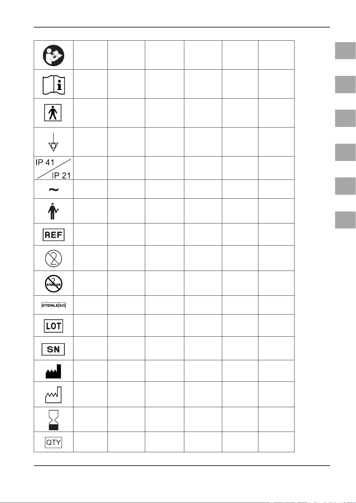
Symbols/Bildzeichen/Symboles/Símbolos/Simboli/Symbolen
Follow instruc-
tions for use
(white image on
a blue back-
ground)
Consult instruc-
tions for use
Type BF applied
part
Equipotentiality
Degrees of pro-
tection Provided
by enclosures
(IP-Code)
Alternating Cur-
rent
Service Service
Gebrauchsanwei-
Gebrauchsanwei-
Gerät des Typs BF
sung befolgen
(weißes Bild auf
blauem Grund)
sung beachten
Potentialaus-
gleich
Gehäuseschutzklasse (IP-Code)
Wechselstrom
Respecter le mode
d’emploi (image
blanche sur fond
bleu)
Consulter pas les
instructions d'utili-
sation
Dispositif de type
BF
Liaison
équipotentielle
Degrés de protection procurés par
les enveloppes
(Code IP)
Courant alternatif Corriente alterna
Service Servicio técnico Assistenza Service
Observar las inst-
rucciones de uso
(imagen blanca
sobre fondo azul)
Tener en cuenta
las instrucciones
de uso
Aparato del tipo BF
Conexión equipo-
tencial
Grado de protección de los envolventes (código IP)
Consultare le
istruzioni per
l'uso (immagine
bianca su sfondo
blu)
Rispettare le
istruzioni per
l'uso
Apparecchio di
tipo BF
Collegamento
equipotenziale
Grado di protezi-
one dell’involu-
cro (codice IP)
Corrente alter-
nata
Gebruiksaanwij-
zing opvolgen
(witte afbeelding
op blauwe onder-
grond)
Gebruiksaanwij-
zing opvolgen
Apparaat van het
type BF
Potentiaalveref-
fening
Beschermings-
klasse (IP-code)
behuizing
Wisselstroom
en
de
fr
es
it
Catalogue num-
ber
Do not reuse
Do not resterilize
Sterilized using
ethylene oxide
Batch code
Serial number
Manufacturer Hersteller Fabricant Fabricante Fabbricante Fabrikant
Date
of manufacture
(YYYY-MM-DD)
Artikelnummer
Nicht wiederver-
wenden
icht resterilisie-
N
ren
Sterilisiert mit
Ethylenoxid
Chargencode
Seriennummer
Herstellungsda-
tum
(JJJJ-MM-TT )
Numéro d’article N.º de referencia Codice articolo Artikelnummer
Ne pas réutiliser No reutilizar Non riutilizzare
Ne pas restériliser No reesterilizar Non risterilizzare
Stérilisé à l’oxyde
d’éthylène
Codes de lot Código de lote Codice lotto Chargecode
Numéro de série Número de serie Numero di serie Serienummer
Date
de fabrication
(AAAA-MM-JJ)
Esterilizado por
óxido de etileno
Fecha
de fabricación
(AAAA-MM-DD)
Sterilizzato con
ossido di etilene
Data
di fabbricazione
(AAAA-MM-GG)
Niet voor hergeb-
ruik
Niet opnieuw ste-
riliseren
Gesteriliseerd
met ethyleen-
oxide
Fabricagedatum
(YYYY-MM-DD)
nl
Use by date
(YYYY-MM-DD)
Quantity
Verwe ndba r bis
(JJJJ-MM-TT )
Menge
Utilisable jusqu’au
(AAAA-MM-JJ)
Quantité Cantidad Quantità Hoeveelheid
Fecha de caducidad (AAAA-MM-
DD)
Da utilizzarsi
entro (AAAA-
MM-GG)
Te gebruiken tot
(YYYY-MM-DD)
Page 6
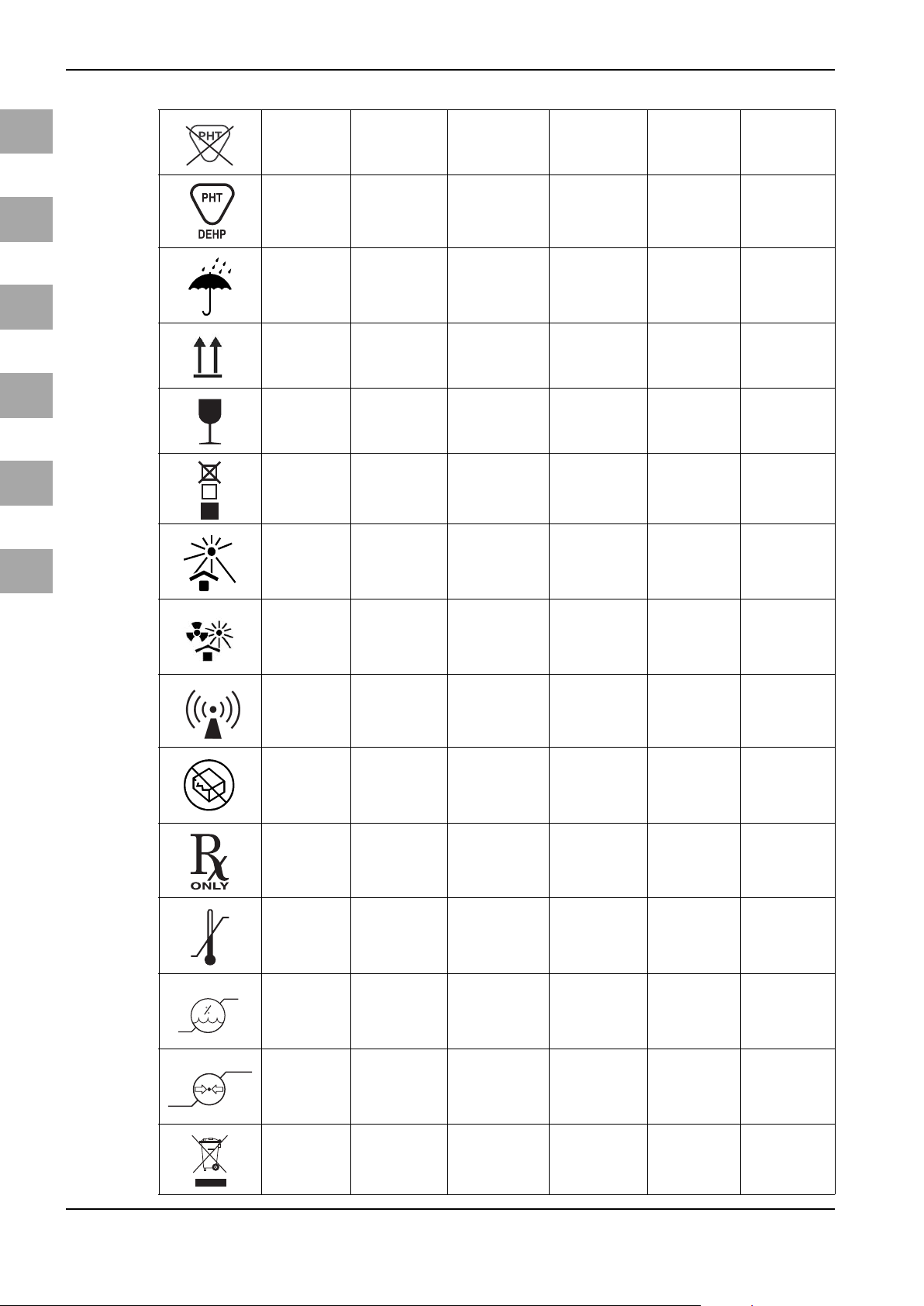
Symbols/Bildzeichen/Symboles/Símbolos/Simboli/Symbolen
1
en
de
fr
es
it
nl
Not made with
phthalates
Contains DEHP Enthält DEHP Contient du DEHP Contiene DEHP Contiene DEHP Bevat DEHP
Keep dry
Top-Bottom
Fragile
Stacking limit by
number
Keep away from
sunlight
Enthält keine
Phthalate
Vor Nässe schüt-
zen
Oben-Unten
Zerbrechlich
Stapelung nach
Anzahl
Vor Sonnenlicht
schützen
Ce produit ne contient pas de phthala-
tes
Protéger de l’humi-
dité
Haut-Bas Arriba-Abajo Alto - basso Boven-Beneden
Fragile Frágil Fragile Breekbaar
Empilage en fonc-
tion du nombre
Protéger des rayons
du soleil
No contiene ftala-
tos
Proteger contra la
humedad
Apilamiento
limitado por
número
Proteger de la luz
solar
Non contiene fta-
lati
Proteggere
dall’umidità
Quantità limite di
impilamento
Proteggere dalla
luce solare
Bevat geen ftala-
Beschermen
tegen vocht
Stapelen volgens
aangegeven aan-
Uit het zonlicht
ten
tal
houden
Protect from
heat and radio-
active sources
Non-ionizing
electomagnetic
radiation
Do not use if
package is
damaged
Authorized for
sale or use by
physician only
Temperature
limit
Humidity limita-
tion
Vor Hitze und
radioaktiver
Strahlung schüt-
zen
Nicht ionisie-
rende elektromag-
netische
Strahlung
Inhalt beschädig-
ter Verpackung
cht verwenden
ni
Nur für authori-
siertes Vertriebs-
personal oder Arzt
Temperaturbe-
grenzung
Luftfeuchte,
Begrenzung
Protéger des sour-
ces chaleur et
radio actives
Rayonnement élec-
tromagnétique
non-ionisant
Ne pas utiliser si
l’emballage est
endommagé
Autorisé seule-
ment pour la vente
ou l’utilisation par
un médecin uni-
quement
Limitation de la
température
Limitation de
l'humidité
Proteger del calor
y de la radiación
radioactiva
Radiación electro-
magnética no ioni-
zante
No utilizar el contenido de envases
dañados
Sólo para distribui-
dores autorizados
o médicos
Limitación de tem-
peratura
Humedad del aire,
limitación
Proteggere dal
calore e da radia-
zioni
Radiazioni elett-
romagnetiche
non ionizzanti)
Non utilizzare il
contenuto di con-
fezioni dann-
eggiate
Solo per personale di vendita
autorizzato o
medici
Limitazione della
temperatura
Limitazione
dell'umidità
dell'aria
Beschermen
tegen hitte en
radioactieve stra-
ling
Niet-ioniserende
elektromagneti-
sche straling
Inhoud van
beschadigde ver-
pakking niet
gebruiken
Uitsluitend voor
bevoegd perso-
neel of arts
Temperatuurbe-
grenzing
Luchtvochtig-
heid, begrenzing
Atmospheric
pressure limi-
tation
Waste Manage-
ment
Luftdruck, Begren-
zung
Entsorgung
Limitation de la
pression atmos-
phérique
Élimination
Presión atmos-
férica, limitación
Eliminación de
residuos
Limitazione della
pressione atmos-
ferica
Smaltimento Verwijdering
Luchtdruk,
begrenzing
Page 7
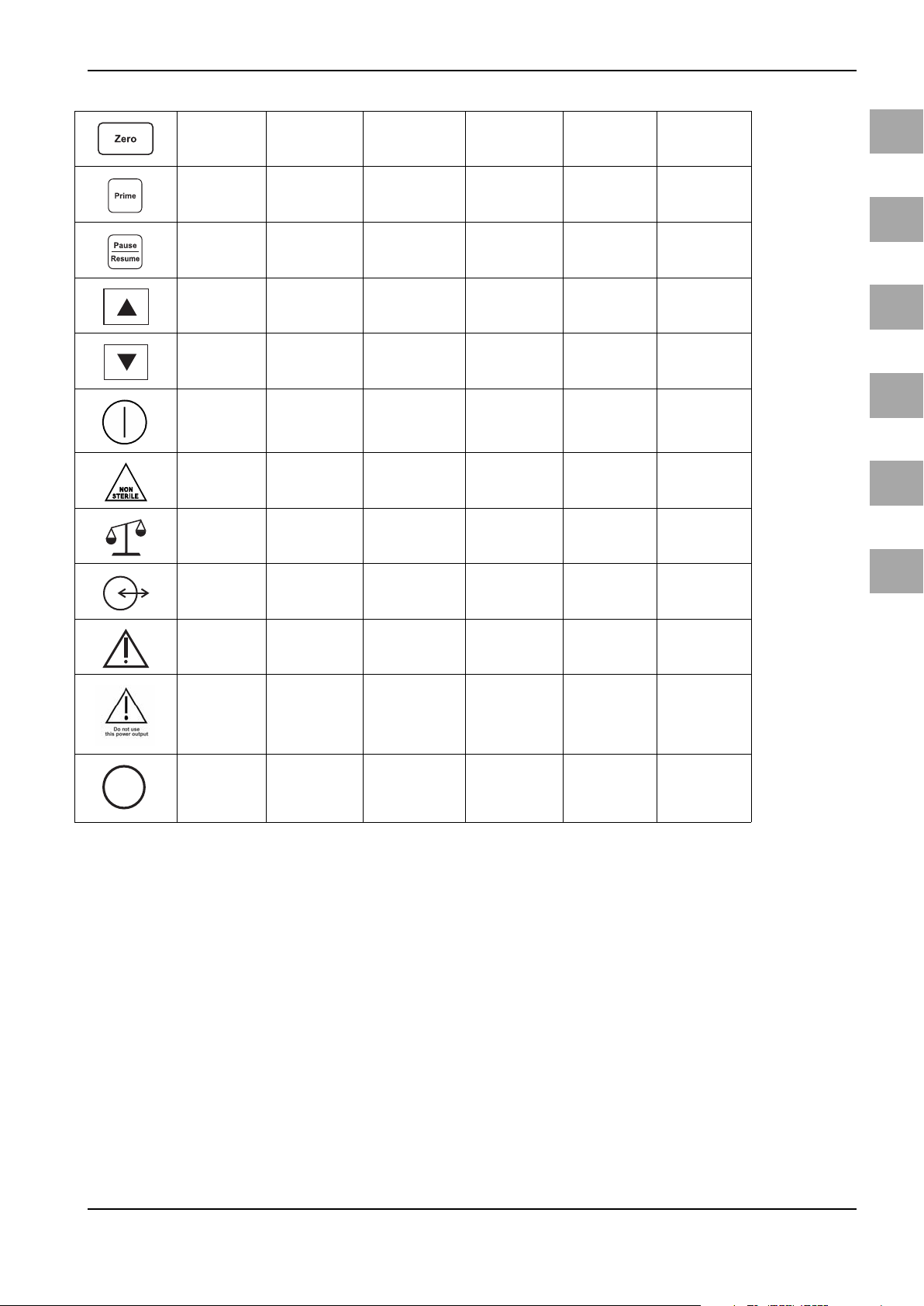
Symbols/Bildzeichen/Symboles/Símbolos/Simboli/Symbolen
MET
C
US
Reset Deficit
Button
Prime Button Taste Prime Touche Prime Tecla Prime Tasto Prime Toets Prime
Pause/Resume
Button
Increase
Decrease Verringern Décroissant Disminución Decrescente Verlagen
On/Off (push
button)
Non sterile Unsteril Non stérile No estéril Non è sterile Niet-steriel
Connection to
Scale
Input/Output Eingang/Ausgang Entrée/sortie Entrada/salida Non spingere! Ingang/uitgang
Tas te Res et De fizit
Tas t e
Pause/Resu me
Erhöhen
Ein/Aus (druckbe-
tätigt)
Anschluss Waage
Touche de remise à
zéro du déficit
Pause/Resume Pause/Resume
Croissant Aumento Crescente Verhogen
Marche/arrêt
(Interrupteur acti-
onné)
Raccordement
balance
Tecl a d e re se teo
del déficit
On/Off ( accionad o
por presión)
Conexión balanza
Tasto di reset per
deficit
Pause/Resume
(Pausa/Riprendi)
Interruttore ON/
OFF (a pressione)
Attacco unità di
pesatura
Resettoets voor
Pause/Resu me
Aan/Uit (druk-
weegsysteem
deficit
knop)
Aansluiting
en
de
fr
es
it
nl
Caution Vorsicht; Achtung Attention Atención Attenzione!
Do not use this
power output
Certification
Mark
Diesen Stromver-
sorgungsanschluss nicht
verwenden
Produktzertifizie-
rung
N'utilisez pas cette
connexion d'ali-
mentation en cou-
rant
Marque de certifi-
cation
No utilice esta
salida de corriente
Marca de certifica-
ción
Non utilizzare
questo attacco di
alimentazione
Marquio de certi-
ficazione
Voorzichtig; Let
op
Deze stroomaans-
luiting niet
gebruiken
Kwaliteitsmerk
Page 8

Page 9

Table of Contents
1 Important Operator/User Notes......................................................................................................................................... 3
2 Safety Information.............................................................................................................................................................. 4
3 Purpose................................................................................................................................................................................ 5
3.1 Warnings and Precautions .................................................................................................................................................... 5
3.1.1 Warnings .................................................................................................................................................................................... 5
3.1.2 Precautions................................................................................................................................................................................. 11
3.2 Description of the Aquilex Fluid Control System ............................................................................................................ 12
4 Initial System Set-up........................................................................................................................................................... 13
4.1 Preparing the System for Use............................................................................................................................................... 13
4.2 System Components................................................................................................................................................................ 14
5 System Operation ............................................................................................................................................................... 15
5.1 Front of Irrigation Pump Unit ............................................................................................................................................... 15
5.2 Rear of Irrigation Pump Unit................................................................................................................................................. 15
5.3 Fluid Monitoring Unit Set-up................................................................................................................................................ 16
5.3.1 Setting of the Container Scale.............................................................................................................................................. 18
5.3.2 Connecting the Vacuum Tube............................................................................................................................................... 19
5.4 Turning On the Aquilex System............................................................................................................................................ 20
5.5 Hanging the Fluid Bags........................................................................................................................................................... 21
5.6 Using Tube Sets......................................................................................................................................................................... 21
5.7 Tube Overview........................................................................................................................................................................... 22
5.8 Connecting the Outflow Tube Set....................................................................................................................................... 23
5.8.1 Connecting Outflow Tube of Tissue Removal Handpiece (e.g. MyoSure®).............................................................. 24
5.9 Inserting the Inflow Tube Set................................................................................................................................................ 25
5.10 Presetting the Intrauterine Pressure .................................................................................................................................. 26
5.11 Deficit Limit Setting................................................................................................................................................................. 26
5.12 Using the Pump during Surgery........................................................................................................................................... 27
5.13 Changing Bags during Surgery............................................................................................................................................. 28
5.14 Changing Container during Surgery................................................................................................................................... 28
5.15 Changing Instrument during Surgery................................................................................................................................ 29
5.16 Total Inflow Volume Displayed............................................................................................................................................. 29
5.17 Turning System Off.................................................................................................................................................................. 29
6 Functional Check................................................................................................................................................................. 30
7 Safety Functions.................................................................................................................................................................. 31
8 Care and Maintenance........................................................................................................................................................ 32
8.1 Cleaning the System................................................................................................................................................................ 32
8.2 Maintenance Carried out by Authorized Service Technician....................................................................................... 32
8.3 Replacing of the Fuse .............................................................................................................................................................. 33
9 Annual Inspection ............................................................................................................................................................... 34
9.1 Safety Test................................................................................................................................................................................... 34
9.2 Basic Function Tests................................................................................................................................................................. 34
9.2.1 Scale Test..................................................................................................................................................................................... 35
9.2.2 Flow Rate Test............................................................................................................................................................................ 35
9.2.3 Pressure Measuring Test ........................................................................................................................................................ 36
9.2.4 Fluid Deficit Measurement Test ........................................................................................................................................... 37
9.2.5 Testing the Vacuum Pump..................................................................................................................................................... 38
9.3 Determine the Software Version......................................................................................................................................... 39
10 Error and Warning Messages.............................................................................................................................................. 40
11 Technical Data..................................................................................................................................................................... 42
12 Guidelines and Manufacturer's Statement - Electromagnetic Compatibility ................................................................... 44
12.1
12.2 Guidelines and Manufacturer’s Statement – Electromagnetic Emissions .............................................................. 45
12.3 Guidelines and Manufacturer's Statement/Electromagnetic Interference Immunity........................................ 46
12.4 Guidelines and Manufacturer's Statement - Electromagnetic Interference Immunity....................................... 47
12.5 Recommended Safety Distances Between Portable and Mobile RF Telecommunications Devices and Aqui-
13 Accessory List ...................................................................................................................................................................... 49
14 Warranty Information ........................................................................................................................................................ 50
15 Glossary............................................................................................................................................................................... 52
16 Appendix ............................................................................................................................................................................. 53
16.1 Test Log........................................................................................................................................................................................ 53
Index.................................................................................................................................................................................... 54
Electrical Connections............................................................................................................................................................. 44
lex Fluid Control System......................................................................................................................................................... 48
en
1
Page 10

Page 11
1Important Operator/User Notes
Read the manual carefully and become familiar with the operation and function
of the Aquilex™ Fluid Control System (Aquilex System) and the accessories before
using the device in the OR. Non-observance of the instructions listed in this manual can lead
• to life-threatening injuries of the patient,
• to severe injuries of the surgical team, nursing staff or service personnel, or
• damage or malfunction of the system and/or accessories.
The manual is only for the Aquilex fluid control system, consisting of pump, container scale and bag scale.
viating slightly from the delivered product due to further development of the
products.
sections with special attention.
WARNING!
Warnings indicate risks to the safety of the patient or operator. Failure to follow
warnings may result in injury to the patient or operator.
Important Operator/User Notes
en
Subject to technical changesThe manufacturer reserves the right to have illustrations and technical data de-
Please noteThe words WARNING, CAUTION, and NOTE carry special meanings. Read these
CAUTION!
Warnings indicate risks to the equipment. Failure to follow cautions may result
in damage to the system.
NOTE!
Notes provide special information to clarify instructions or present additional in-
formation.
3
Page 12

en
Safety Information
2 Safety Information
Exclusion of liability Hologic is not liable for direct or consequential damage and the warranty is null
and void if:
• the system and/or the accessories are operated and used by untrained personnel,
• the system and/or the accessories are improperly used, prepared, or maintained,
• the instructions and rules in the user/operator manual are not adhered to,
• unauthorized persons perform repairs, adjustments, or alterations on or to the
system or accessories,
• unauthorized persons open the system,
• the prescribed inspection and maintenance schedule is not adhered to.
Receipt of technical documentation from Hologic does not authorize individuals
to perform repairs, adjustments, or alterations on or to the system or accessories.
Authorized service technician Only an authorized service technician may perform repairs, adjustments, or al-
terations on the system or accessories. Any violation will void the manufacturer's
warranty. Authorized service technicians are trained and certified only by the
manufacturer.
Normal Use The system may be used only as intended.
Care and maintenance The service and maintenance of the device and its accessories has to be carried
out as per instructions to ensure the safe operation of the device. For the protection of the patient and the operating team, check that the device is complete and
functional before each use.
Maintenance of the device may not be performed during the operation.
Contamination Before shipping, decontaminate device and accessories in order to protect the
service personnel. Follow the instructions listed in this manual. If this is not possible,
• the product must be clearly marked with a contamination warning and
• is to be double-sealed in safety foil.
The manufacturer has the right to reject contaminated products for repair.
Waste management In the European Community, this symbol indicates that the waste of electrical
and electronic equipment must not be disposed of as unsorted municipal waste
and must be collected separately instead. Please contact Hologic or an accordingly authorized disposal or waste management company for further information.
4
Page 13
3 Purpose
uterus during diagnostic and operative hysteroscopies and to monitor the volume differential between the irrigation fluid flowing into and out of the uterus.
py is contraindicated. See the operators manual of your hysteroscope for absolute and relative contraindications.
Relative contraindications to endometrial ablation:
Hysteroscopic endometrial ablation, whether by laser or electrosurgery, should
not be undertaken before adequate training, preceptorship, and clinical experience. Additionally, tissue sampling is required prior to destruction of the endometrium. The following are clinical conditions that can significantly complicate
hysteroscopic endometrial ablation:
• Adenomatous endometrial hyperplasia
•Uterine leiomyoma
• Severe adenomyosis
• Pelvic pain (subtle PID)
• Uterine anomalies
• Surgical skill (see above)
• Severe anemia
• Inability to circumnavigate the myoma (re: myoma size) - predominantly intramural myomas with small submucous components.
Purpose
Intended UseThe Aquilex™ Fluid Control System is intended to provide fluid distension of the
ContraindicationsThe system may not be used to introduce fluids into the uterus when hysterosco-
en
3.1 Warnings and Precautions
3.1.1 Warnings
WARNING!
When performing monopolar hysteroscopic electrosurgery, the distension medium must be electrically non-conductive. Examples include glycine, sorbitol and
mannitol. Isotonic saline irrigation fluids may only be used when performing bipolar electrosurgical resective procedures.
WARNING!
The pressure should be kept as low as possible to allow for a sufficient intrauter-
ine distension and to reduce the forces that could allow fluid, ambient air, and/
or gas to enter the circulatory system.
WARNING!
Intrauterine distention is usually possible with pressure values between 35 to
70 mmHg. A pressure above 75 to 80 mmHg is required only in rare cases or if the
patient has an excessively high blood pressure.
WARNING!
Fluid overload
There is a risk of irrigation fluid reaching the circulatory system of the patient's
soft tissue by passing through the uterus. This can be affected by distention pressure, flow rate, perforation of the uterine cavity and duration of the hysteroscopic surgery. It is critical to closely monitor the input and outflow of the
distending liquid at all times.
5
Page 14
en
Purpose
WARNING!
Fluid deficit
The fluid left in the patient must be monitored. The deficit is the total amount of
fluid left in the patient or unaccounted for otherwise. Take notice of the measurement tolerance of the system (see Chapter 11, Technical Data). Estimating
the fluid volume remaining in the patient is the physician’s responsibility.
WARNING!
Fluid intake and output surveillance
Strict fluid intake and output surveillance should be maintained. If a low viscos-
ity fluid distention medium is used, intrauterine instillation exceeding 2 liters
should be followed with great care due to the possibility of fluid overload.
WARNING!
Serum sodium concentration
It is also necessary to monitor the concentration of sodium in the blood of the pa-
tient to prevent electrolyte disturbances. Monitoring of the concentration of sodium in the blood must be performed by the physician and is not performed or
supported by the system.
WARNING!
The deficit display value is lost in case of a power loss or “brownout.”
WARNING!
If the message “Check Scale Connection” appears, the deficit must be calculated
manually. The pump keeps displaying the last known deficit value determined
prior to the failure of the scale connection.
WARNING!
A container change during surgery is only allowed, if the container holds at least
0,5 liters of fluid. Otherwise, the deficit value may be falsified. In this case, the
manufacturer recommends manual deficit calculation.
WARNING!
Hyponatremia
Some distension fluids may lead to fluid overload and, consequently, hyponatre-
mia with its attending sequelae. This can be affected by the distending pressure,
flow rate, and duration of hysteroscopic procedure. It is critical to closely monitor the input and outflow of the distending liquid at all times.
WARNING!
Pulmonary edema
Hysteroscopic surgery is associated with a risk of developing pulmonary edema
resulting from fluid overload with isotonic fluids. It is critical to closely monitor
the input and outflow of the distending liquid at all times.
6
Page 15
WARNING!
Cerebral edema
Hysteroscopic surgery is associated with a risk of developing cerebral edema re-
sulting from fluid overload and electrolyte disturbances with hypoosmolar (nonionic) fluids such as glycine 1.5 % and sorbitol 3.0 %. It is critical to closely monitor the input and outflow of the distending liquid at all times.
WARNING!
Idiosyncratic reactions
In rare cases, idiosyncratic reactions, including:
• intravascular coagulopathy
• allergic reaction including anaphylaxis
may occur while performing a hysteroscopy if a liquid distention medium is used.
WARNING!
Hypothermia (monitoring body temperature)
Continuous flow of distention fluids can lead to a lowering of the patient's body
temperature during hysteroscopic surgery. Lower body temperatures can cause
coronary and cardiovascular problems. Always monitor the patient's body temperature during the entire surgery. Make especially sure that the following, hypothermia promoting, operation conditions are avoided as best as possible:
• longer operating times
• use of cold irrigation fluid.
Purpose
en
WARNING!
Rupture of the fallopian tube secondary to tubal obstruction
Distention of the uterus may lead to a tear of the fallopian tube should there be
an obstruction or permanent occlusion. The rupture could lead to irrigation fluid
flowing into the patient's peritoneal cavity, resulting in a fluid overload. It is critical to closely monitor the input and outflow of the distending liquid at all times.
WARNING!
An air embolism can be the result of air contained in the tube set or connected
instrument reaching the patient. Ensure there is always fluid in the bag to prevent air from being pumped into the patient.
WARNING!
The system is only intended for use with flexible fluid containers. Do not use
glass containers as they might break. With rigid containers, fluid cannot flow
quickly enough due to the vacuum being generated inside of the containers. Risk
of implosion with rigid containers.
WARNING!
Filling the tubing with irrigation fluid and resetting the deficit display to zero are
to be done at the physician’s discretion.
7
Page 16
en
Purpose
WARNING!
Place the system in such a way as to allow for easy visualization of the display
values, system functions, and access to the control elements.
WARNING!
Functional test
The functional test must be performed prior to each device use.
WARNING!
Do not use this system if a defect is suspected or detected during the function
check. This also applies to obvious defects, especially defects and damage to the
power plug and power cord.
WARNING!
Pressing the ON/OFF switch does not disconnect the system from the wall power
outlet. This requires pulling the power cord located in the rear of the system.
WARNING!
Technique and procedures
Only the physician can evaluate the clinical factors involved with each patient
and determine if the use of this system is indicated. The physician must deter-
mine the specific technique and procedure that will accomplish the desired clinical outcome.
WARNING!
Check all factory settings
Factory settings are not mandatory settings for the physician. The physician is responsible for all settings affecting the surgical procedure.
WARNING!
Original accessories
For your own safety and that of your patient, use only Aquilex accessories.
WARNING!
Additional equipment
Additional equipment connected to medical electrical devices must be demonstrated to be compliant with their respective IEC or ISO standards (IEC 60601-1,
IEC 60950 or IEC 62368 for data processing equipment).
WARNING!
Not explosion-proof
The system is not explosion-proof. Do not use in an area where flammable anes-
thetic gases are present.
8
Page 17
WARNING!
Changes to the system are not allowed.
WARNING!
To avoid risk of electrical shock, this system may only be connected to a supply
mains with protective earth.
WARNING!
Professional qualification
This manual does not include descriptions or instructions for surgical proce-
dures/techniques. It is also not suitable for training physicians in the use of surgical techniques. Medical instruments and systems may be used only by
physicians or medical assistants with the appropriate technical/medical qualification working under the direction and supervision of a physician.
WARNING!
Sterile media and accessories
Always work exclusively with sterile substances and media, sterile fluids, and
sterile accessories, if so indicated.
Purpose
en
WARNING!
Replacement system and accessories
In case the system or any of the accessories fail during a procedure, an alterna-
tive system and replacement accessories should be kept within easy reach to be
able to finish the operation with the replacement components.
WARNING!
Cleaning the system / Sterilization not allowed.
The pump and the cart/scale can be disinfected by wiping off the outer surfaces.
Do not sterilize the pump and the cart/scale.
WARNING!
Condensation / Water penetration
Protect system from moisture. Do not use if moisture has penetrated the system.
WARNING!
System defect
If a system defect is suspected or confirmed, do not use the system. Ensure the
system will no longer be used until a qualified service technician conducts the
appropriate tests and repairs.
WARNING!
Risk of electrical shock
To prevent electrical shock, do not open this device. Never open this device yourself. Refer servicing to qualified service personnel.
9
Page 18
en
Purpose
WARNING!
Replacing fuse
Replace the fuse only with a fuse of the same type and rating (see Chapter 11,
Technical Data).
WARNING!
Equipment should be positioned such that power cord can be easily disconnect-
ed.
WARNING!
Electromagnetic emissions may increase and rise above the permissible limits if
other equipment (e.g. MyoSure® Control Unit) is stacked onto or placed directly
next to the Aquilex Fluid Control System. The user is responsible for monitoring
the devices to make sure they function properly.
WARNING!
Electrical Interference (see Chapter 12, Guidelines and Manufacturer's State-
ment - Electromagnetic Compatibility): Electrical interference with other devices
or instruments was considered when developing this system and none was detected during testing. However, if you still detect or suspect such interference,
please follow these suggestions:
• Move the Aquilex System, the other device, or both devices to a different location
• Increase distance between devices used
• Consult an electro-medical expert
WARNING!
The Aquilex Fluid Control System should not be used directly next to other devices as this could result in malfunctions. The Aquilex Fluid Control System was test-
ed for compliance with IEC 60601-1-2 as a stand alone system. Therefore, do not
stack other devices (e.g. MyoSure® Control Unit) on the system or the Irrigation
Pump Unit. In particular, do not place any other device than the AQL-100P on the
trays of the AQL-100CBS. If usage in the manner described above is nevertheless
required, this system and the other devices should be monitored to make sure
they function properly.
WARNING!
If the Aquilex Fluid Control System is configured as part of a ME SYSTEM, the en-
tire ME SYSTEM should be tested for compliance with IEC 60601-1-1, and any
equipment used with the Aquilex Fluid Control System should be Type BF.
WARNING!
If the leakage current of the configured ME SYSTEM exceeds the limits of IEC
60601-1-1, install an appropriately rated UL 2601-1/IEC 60601-1 approved isola-
tion transformer and retest the system.
10
Page 19
WARNING!
Always use the hooks of the bag scale to hang the fluid bags to ensure an accu-
rate determination of the fluid deficit. In addition, leave the empty fluid bags
hanging on the bag scale until the end of surgery.
3.1.2 Precautions
CAUTION!
Federal Law (only for U.S. market)
Federal law restricts this device to sale by or on the order of a physician.
CAUTION!
Indoor climate
Before switching on the device, sufficient time must have passed to adjust to the
indoor climate.
CAUTION!
When using the Aquilex System with tissue removal systems, e.g. MyoSure®, the
combination of low set pressures and excessive vacuum pressures may result in
a significant loss of intrauterine distension pressure which has the potential to
affect the visibility of the surgical field. Conversely, when employing a high distension pressure, the deactivation of the tissue removal system can lead to pressure spikes that can exceed 150 mmHg.
Purpose
en
CAUTION!
Do not use the covered power output at the rear of the irrigation pump unit.
CAUTION!
The system may only be connected with hysteroscopes designed for and featur-
ing the technical specification permitting such a combined use. Any utilized hysteroscopes must comply with the most recent versions of IEC 60601-2-18 and
ISO 8600.
CAUTION!
Check to ensure the available wall outlet voltage matches the data listed on the
label attached to the back of the pump. Incorrect voltage can cause errors and
malfunctions and may destroy the system.
CAUTION!
The device is transportable. The roller wheels of the Fluid Monitoring Unit (cart/
scale) are used for positioning at the place of use. To transport the device, re-
move all fluid bags from the hooks and make sure there are no containers or only
completely emptied containers on the cart/scale. Inflow and outflow tubes must
be completely removed. Make sure the power supply line does not touch the
ground and there are no other objects located on the Aquilex fluid control system. Always use the handle to move the system safely.
11
Page 20

en
Purpose
CAUTION!
To avoid affecting the accuracy of the deficit calculation ensure that the first step
of the container change is to disconnect tubing from the full containers. Remove
full containers from the scale immediately after that.
Only for U.S. operators Only use a certified (UL-listed), removable mains connection cable, type SJT, min-
imal 18 AWG, 3 leads. The plug connectors must comply with NEMA 5-15 and
IEC 16320-C13. Grounding will only be reliable if the equipment is connected to
a corresponding hospital grade socket.
3.2 Description of the Aquilex Fluid Control System
Technical application scope of the system
Suggested distension media The Aquilex Fluid Control System can be used with hypotonic, electrolyte-free
The intrauterine pressure can be adjusted on the front of the pump. It can be pre-set
to a range between 40 and 150 mmHg. The maximun inflow rate is 800 ml/min and
is reduced automatically by the pump once the pre-set intrauterine pressure setting
has been reached.
The system has been designed to provide both fluid and vacuum systems that
maximize the performance of tissue removal systems, e.g. MyoSure®.
media (e.g., glycine 1.5% and sorbitol 3.0%) and isotonic, electrolyte containing
media (e.g., saline 0.9% and Lactated Ringer's).
Pressure measuring and regulating The system operates with a completely non-contact pressure measurement of
the irrigation medium. The contact-free pressure measurement is achieved by integrating the pressure chamber into the tubing system. The pressure chamber
transmits the irrigation fluid pressure to the electronics of the device via a pressure sensor. The pressure control circuit continuously compares the desired preset intrauterine pressure with the actual intrauterine pressure. The function of
this algorithm is to maintain the pre-set intrauterine pressure. Check for possible
leaks if the pre-set intrauterine pressure cannot be achieved.
12
Page 21
4 Initial System Set-up
Always check all parts and accessories of the system when performing initial setup. If the system has obvious defects, contact Hologic Technical Support (Chapter
14, Warranty Information).
temperature and humidity must meet the requirements mentioned in Chapter
11, Technical Data.
WARNING!
Equipment should be positioned such that power cord can be easily disconnected.
CAUTION!
Indoor climate
Before switching on the device, sufficient time must have passed to adjust to the
indoor climate.
4.1 Preparing the System for Use
Initial System Set-up
en
Initial system set-upPlace the system on a level surface and install in a dry environment. The ambient
WARNING!
The Aquilex Fluid Control System should not be used directly next to other devices as this could result in malfunctions. The Aquilex Fluid Control System was test-
ed for compliance with IEC 60601-1-2 as a stand alone system. Therefore, do not
stack other devices (e.g. MyoSure® Control Unit) on the system or the Irrigation
Pump Unit. In particular, do not place any other device than the AQL-100P on the
trays of the AQL-100CBS. If usage in the manner described above is nevertheless
required, this system and the other devices should be monitored to make sure
they function properly.
CAUTION!
Check to ensure the available wall outlet voltage matches the data listed on the
label attached to the back of the system. Incorrect voltage can cause errors and
malfunctions and may destroy the system.
Ensure the connection data and technical specifications of the power supply
comply with DIN VDE or national requirements. The wall outlet power supply
cord must be plugged into a properly installed safety wall plug (see DIN VDE
0107). Read the device label located in rear of pump to determine the operating
voltage of the system.
uilex power cord to establish a connection between the wall outlet and the power cord connection located in the rear of the system.
Connection to the wall outlet
Grounding contactThe power connection must be equipped with a grounding contact. Use the Aq-
3 leads. The plug connectors must comply with NEMA 5-15 or IEC 320/CEE22.
Grounding will only be reliable if the equipment is connected to a corresponding
hospital grade outlet.
safety rules and regulations.
Only for U.S. operatorsUse only a certified (UL-listed), removable power cord, type SJT, minimal 18 AWG,
Potential equalizationIntegrate the system into the potential equalization system as specified by local
13
Page 22
en
(4)
(6)
(1)
(7)
(2)
(3)
(5)
Initial System Set-up
Precautionary measures Medical devices are subject to special safety and protective measures concerning
electromagnetic compatibility (hereafter abbreviated as EMC).
This system is to be used only for the purposes described in the manual and has
to be installed, set up, and operated in compliance with the EMC notes and instructions.
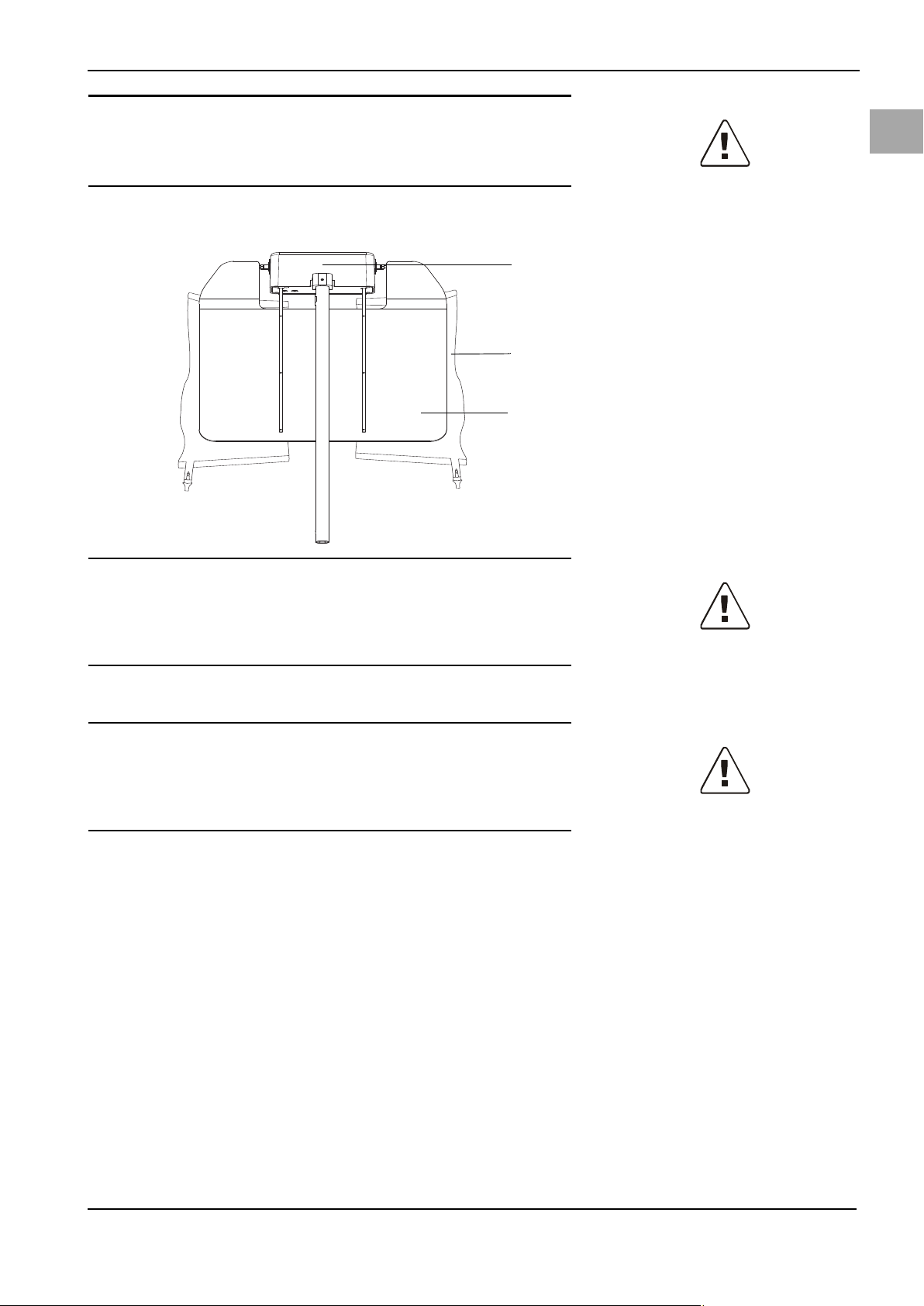
4.2 System Components
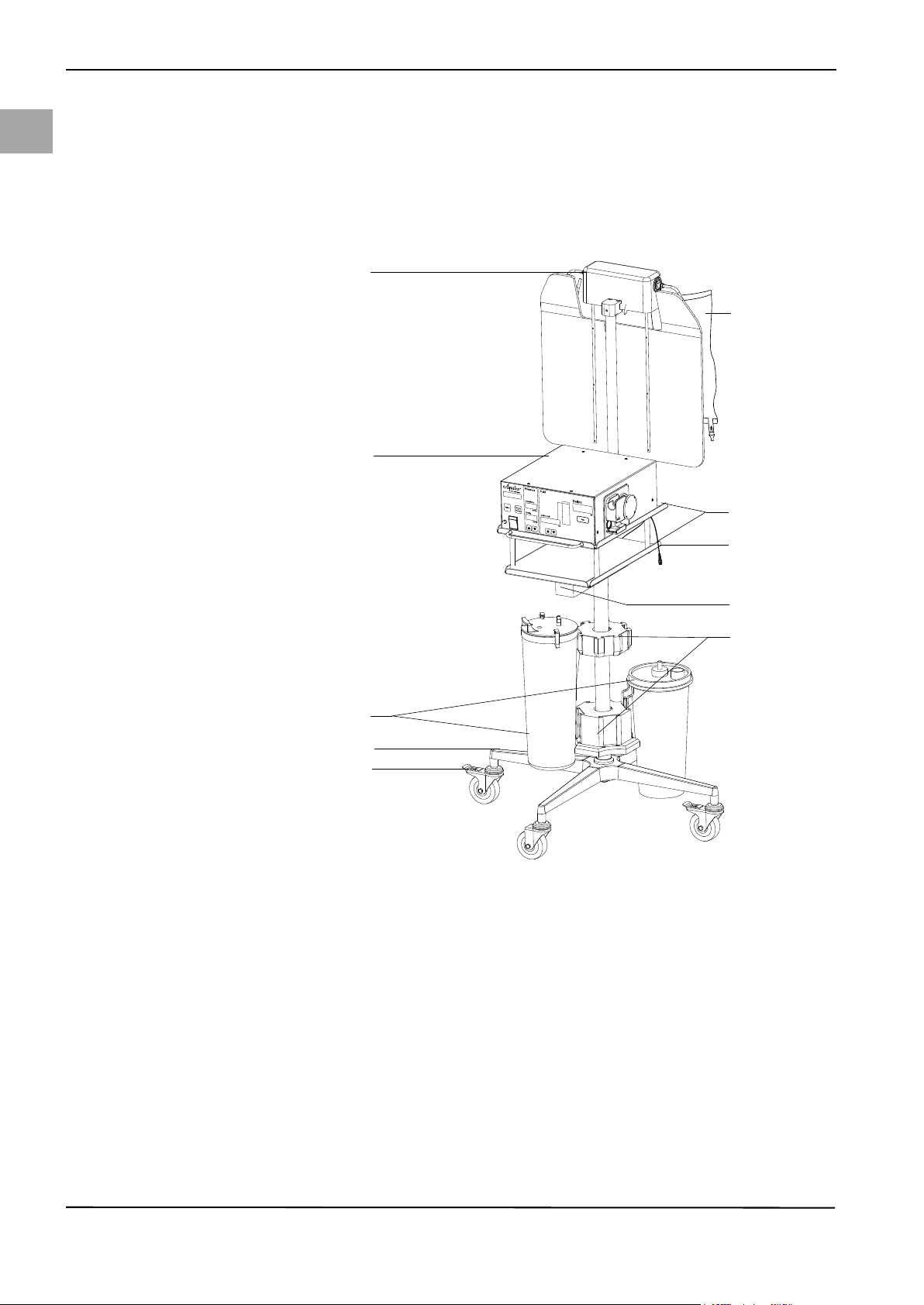
Fig. 4-1 System Components
(1) Bag scale
(2) Fluid bag
(3) Irrigation Pump Unit
(4) Tr ay s
(5) Container scale cable/connector
(6) Container scale
(7) Container holders
(8) Container
(9) Roller wheel base
(10) Locking foot brake
The Aquilex Fluid Control System is divided into two separate boxes for shipping:
Box 1 contains:
• Irrigation Pump Unit
• Instructions for Use
•Power cord
• Aquilex system vacuum tube set (low and high vacuum)
Box 2 contains:
• Fluid Monitoring Unit (cart with scale)
•Container rings
14
Page 23
5System Operation
(11)
(1)
(2)
(3)
(7)(4)
(5)
(6)
(8)
(9)
(10)
(13)
(16)
(17)
(15)
(14)
(12)
H
I
G
H
L
O
W
Potential
Equalization
Low
Medium
High
Aquilex Fluid Control System
TM
Ser.Nr. WOM /
100-240V / 50-60 Hz
YYYY-MM
TYPE
SN / REF
MyoSure
®
only for
(6)
(5)
(4)
(9)
(1)
(2)
(3)
(8)
(10)
(11)
(12)
(12)
(7)
Please make sure that the functional check according to chapter 6 has been performed prior to each device use.
5.1 Front of Irrigation Pump Unit
Please familiarize yourself with the layout of the individual elements on the front
of the pump.
5.2 Rear of Irrigation Pump Unit
System Operation
en
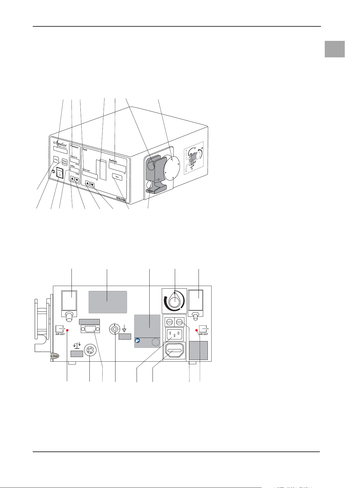
Fig. 5-1 Front of Irrigation Pump Unit
(1) Pump display
(2) Intrauterine pressure display
(3) Fluid deficit limit display
(4) Deficit meter
(5) Deficit display
(6) Inflow tube holder
(7) Roller wheel
(8) Pressure sensor
(9) Reset deficit button (Zero)
(10) Decrease deficit limit
(11) Increase deficit limit
(12) Decrease intrauterine pressure set-
ting
(13) Increase intrauterine pressure set-
ting
(14) Intrauterine pressure setting dis-
play
(15) ON/OFF switch
(16) Pause/Resume button
(17) Prime button
Please familiarize yourself with the layout of the individual elements at the rear
of the pump.
Fig. 5-2 Rear of Irrigation Pump Unit
(1) Connection for low vacuum
(white)
(2) Product label
(3) Performance data of the device
(4) Adjustment controller for high
vacuum
(5) Connection for high vacuum
(green)
(6) Fuse holder
(7) Covered power output
(8) Power connection for pump
(9) Potential equalization connection
(10) Service interface
(11) Connection for scale
(12) Suction openings
15
Page 24
en
(3)
(9)
(4)
(6)
(1)
(7)
(2)
(8)
(5)
System Operation
CAUTION!
Do not use the covered power output at the rear of the irrigation pump unit.
WARNING!
Additional equipment
Additional equipment connected to medical electrical devices must be demon-
strated to be compliant with their respective IEC or ISO standards (IEC 60601-1,
IEC 60950 or IEC 62368 for data processing equipment).
5.3 Fluid Monitoring Unit Set-up
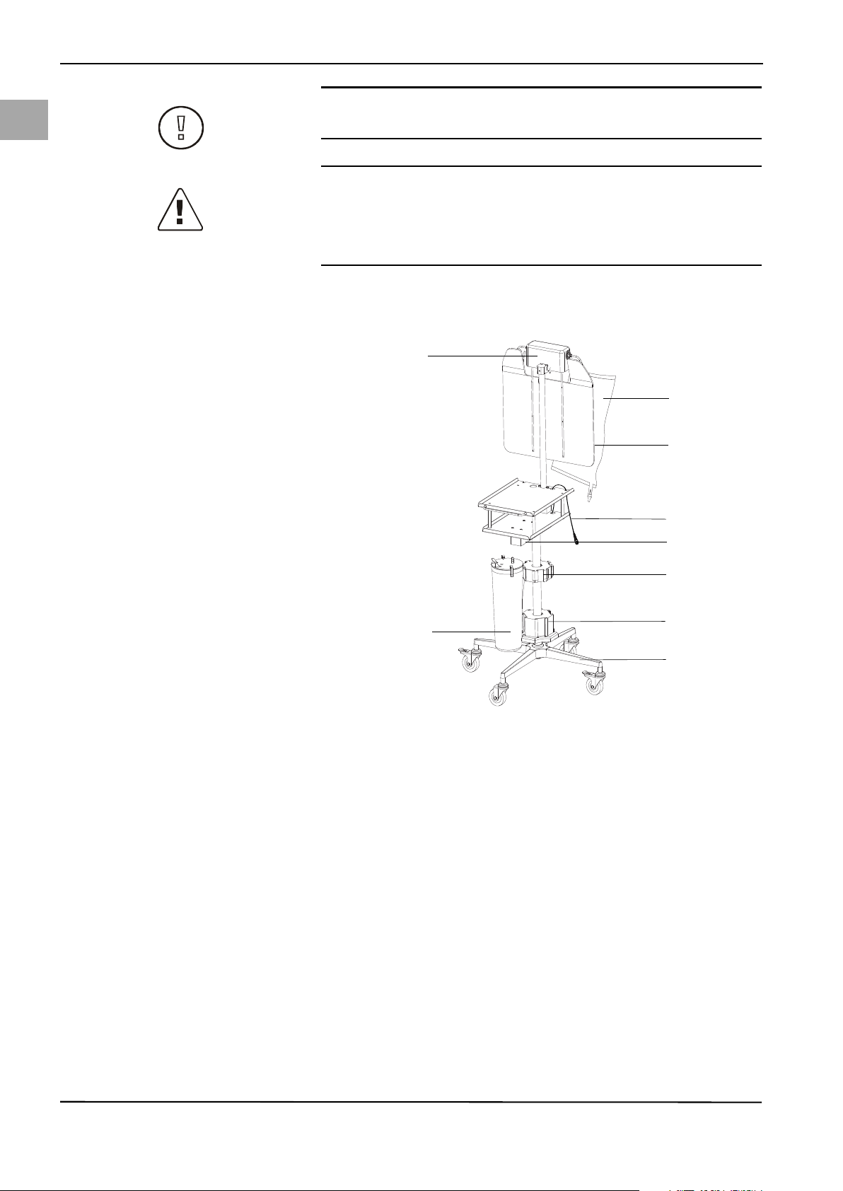
Fig. 5-3 Fluid Monitoring Unit (cart
with scale)
(1) Bag scale
(2) Fluid bags
(3) Bag deflector
(4) Container scale cable/connector
(5) Container scale
(6) Holder for upper container (Serres,
Medela)
(7) Holder for lower container
(Abbott, Bemis®, Medi-Vac®,
DeRoyal®)
(8) Roller wheel base
(9) Container
16
The fluid monitoring unit (cart/scale) consists of a weighing unit for fluid bags
(1), a weighing unit for fluid containers (5), and a roller wheel base (8).
1. Remove the cart/scale from the cardboard shipping box.
2. Remove the pump and the power cords from the first cardboard box.
3. Loosen the handwheel (6) (Fig. 5-4, page 17) and pull bag scale upwards to
stop. The screw (7) (Fig. 5-4, page 17) must be inserted into the provided
opening. Secure the bag scale with the handwheel.
4. Depending on the type of container used, attach the container rings (included
in the second box) to the upper (6) or lower (7) container holders ( Fig. 53, page 16).
5. Guide the power cord through the holes provided for this purpose and connect to pump (2) (Fig. 5-4, page 17) and plug into grounded, shockproof safety wall socket.
6. Attach the scale to the pump by connecting the connector of the bag scale
with the connector of the container scale (4) (Fig. 5-4, page 17) and fix the
connected cables below the lower pump tray by means of the provided wire
clips. Connect the second connector of the bag scale to the port on the back
of the pump (5) (Fig. 5-4, page 17).
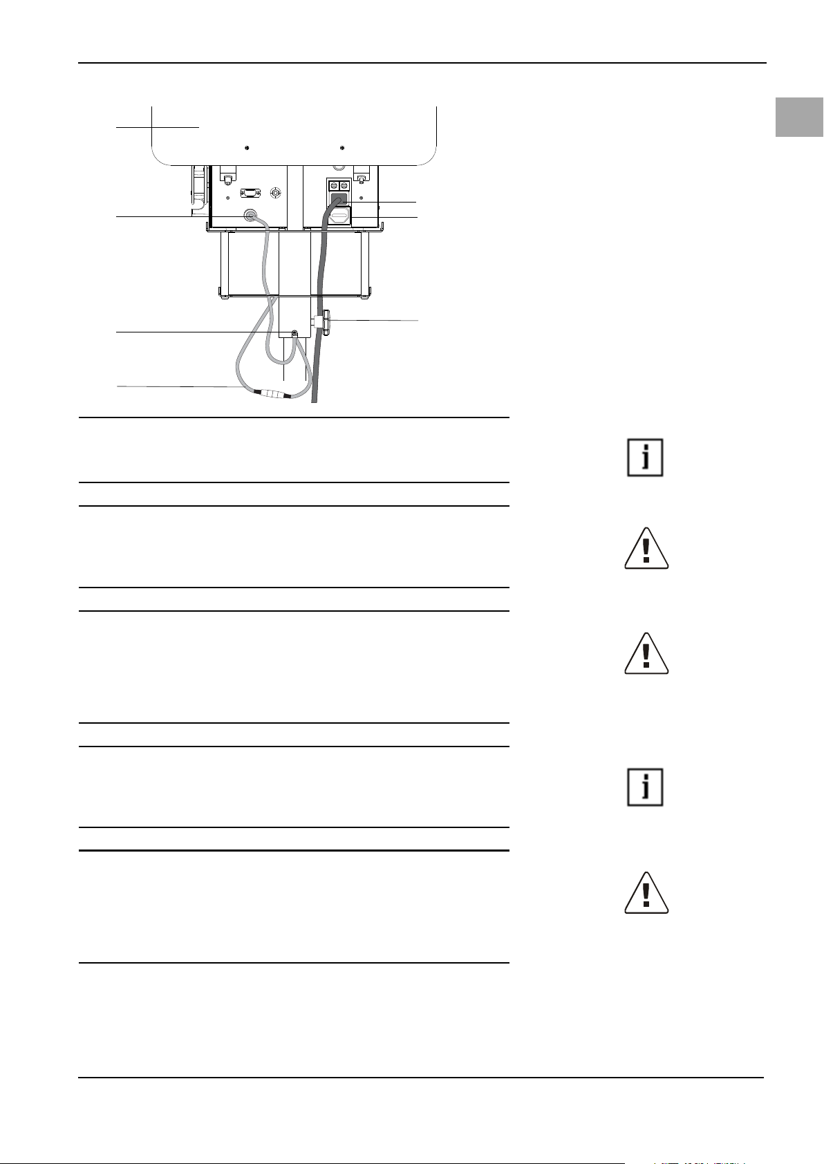
Page 25
System Operation
(1)
(2)
(3)
(5)
(4)
(6)
(7)
NOTE!
The pump's software automatically detects whether the container scale and bag
scale are connected or only the container scale.
Fig. 5-4 Scale and pump connection
(1) Bag deflector
(2) Power cord/pump connection
(3) Covered power output
(4) Plug connection, bag scale with
container scale
(5) Bag scale connector, connection to
pump
(6) Handwheel
(7) Screw
en
WARNING!
Scale error
Ensure that nothing weighs down the scale during system start-up. Doing so
may result in an inaccurate deficit value.
WARNING!
Fluid deficit
The fluid left in the patient must be monitored. The deficit is the total amount of
fluid left in the patient or unaccounted for otherwise. Take notice of the measurement tolerance of the system (see Chapter 11, Technical Data). Estimating
the fluid volume remaining in the patient is the physician’s responsibility.
NOTE!
The greater the consumption of irrigation fluid, the greater the deviation be-
tween the actual and the displayed deficit (see "Technical Data," deficit accuracy: ± 6%).
WARNING!
Serum sodium concentration
It is also necessary to monitor the concentration of sodium in the blood of the pa-
tient to prevent electrolyte disturbances. Monitoring of the concentration of sodium in the blood must be performed by the physician and is not performed or
supported by the system.
to achieve the most exact deficit value possible.
Precise balancingTry to collect all the fluid running out of the uterine cavity during the procedure
Scale capacityThe container scale can be loaded with a weight of up to 25 kg (55 lbs). The max-
imum load of the bag scale is 12 kg (27 lbs). If the scales are loaded beyond these
17
Page 26
en
System Operation
limits, the message Scale Overload/Check Scale is triggered and displayed. Three
audible warning beeps are emitted as well (See Chapter 10, Error and Warning
Messages.)
CAUTION!
Make sure the containers and fluid bags hang freely, are not resting on some-
thing, and do not touch other objects except the bag deflectors. Failure to follow
these instructions means the deficit cannot be calculated correctly.
NOTE!
Connect the scale to the pump before turning the system on to ensure the system recognizes the scale.
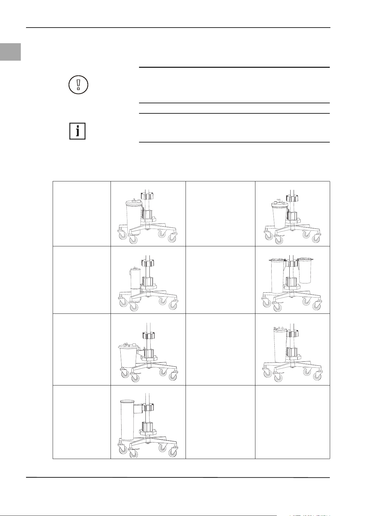
5.3.1 Setting of the Container Scale
The container scale can be used with containers from different manufacturers.
Bemis®3 liters DeRoyal® Crystaline™ 2.1 l
Abbott 2 liters Serres 2 & 3 liters
Medi-Vac® 3 liters Medela 3 liters
Medi-Vac Flex Advantage 3000 cc
18
Page 27
NOTE!
W.O.M. WORLD O
F M
EDICINEAG
10587 B
erlin•Salzufer
8
•GERMANY
+49
(
0) 30 3
99
8
1-550(
96337 L
udwigsstadt•Alte P
oststraße 1
1
GERMANY• +49 (
0)
9263 8
77-0(
M
anu
fa
cturer
Aquilex FluidControl System
TM
Ser.Nr.WOM /
100-240V/50-60Hz
YYYY-MM
(3)
(4)
(2)
(1)
(5)
Ensure containers are positioned properly in the respective holders.
NOTE!
Only use containers with overflow protection.
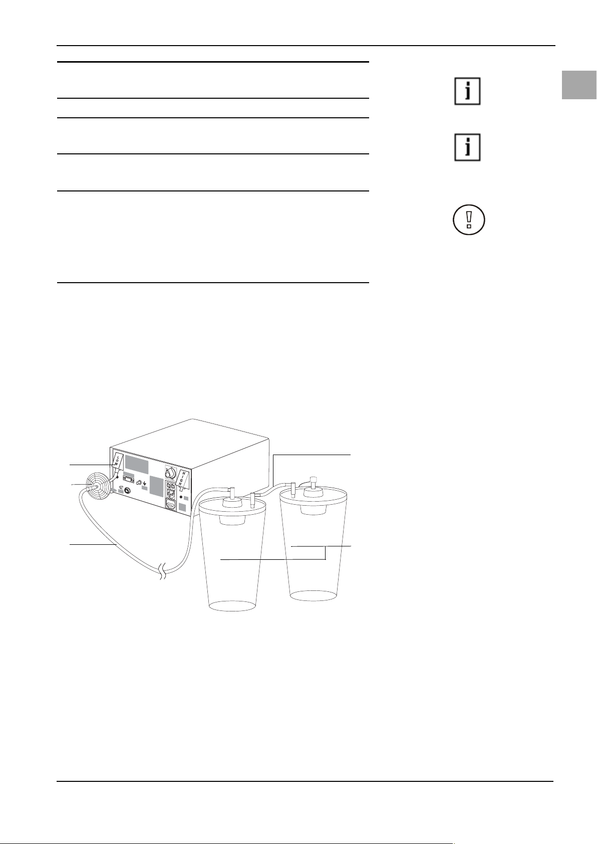
5.3.2 Connecting the Vacuum Tube
CAUTION!
When using the Aquilex System with tissue removal systems, e.g. MyoSure®, the
combination of low set pressures and excessive vacuum pressures may result in
a significant loss of intrauterine distension pressure which has the potential to
affect the visibility of the surgical field. Conversely, when employing a high distension pressure, the deactivation of the tissue removal system can lead to pressure spikes that can exceed 150 mmHg.
Connect vacuum tube with hygiene filter to suction containers. The vacuum tube
with hygiene filter must be replaced when dirty and after 30 days at the latest.
The vacuum tube with hygiene filter should not be cleaned.
System Operation
en
• Connection for low vacuum (white)
· Connect vacuum tube with white connector to low vacuum port (white) (1)
Fig. 5-5. This vacuum pump has a fixed vacuum pressure (~ 225 mmHg).
· Use the connecting tube ((5) Fig. 5-5) when two containers are serially con-
nected to the same vacuum port.
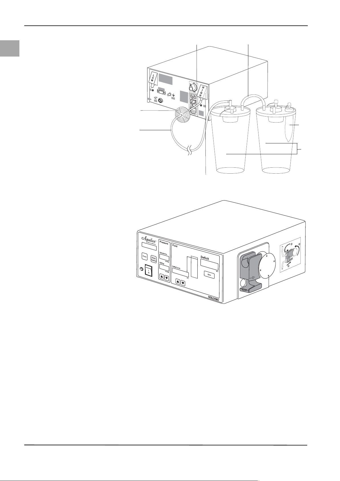
• Connection for high vacuum (green)
· Connect vacuum tube set with the green connectors to the high vacuum
port (green) (8) in Fig. 5-6. This vacuum can be adjusted to a maximum
500 mmHg using adjustment dial.
· Use the connecting tube ((12) Fig. 5-6) when two containers are serially
connected to the same vacuum port.
Fig. 5-5 Low vacuum tube
(1) Connection for low vacuum
(white)
(2) Hygiene filter
(3) Vacuum tube
(4) container
(5) Connecting tube
19
Page 28
System Operation
M
yoSure
®
only for
(8)
(9)
(6)
(10)
(11)
(12)
en
Fig. 5-6 High vacuum tube
(6) Hygiene filter
(7) Vacuum tube (green connectors)
(8) Connection for high vacuum
(green)
(9) Container
(10) Tissue trap
(11) Adjustment dial
(12) Connecting tube
5.4 Turning On the Aquilex System
20
1. Press the ON/OFF switch. The displays and indicators light up and system
turns on.
2. The system now performs a device self-test.
The device self-test is used by the system to check whether the container and
the bag scale are connected, among others. If the bag scale is not connected,
the message "System OK. Bag Scale Not Connected” is displayed. In this case,
please check the appropriate data connection of the scales with the pump according to chapter 5.3.
3. If a tube set is in the inflow tube holder when the pump is switched on, the
pump display (Fig. 5-1, Front of Irrigation Pump Unit (1)) shows the message
Remove Tube Set. The device self-test resumes once the tube set is removed
from the roller wheel.
If the device self-test is unsuccessful, the corresponding error messages are
displayed (see Chapter 10, Error and Warning Messages).
The system has successfully completed the device self-test when a single audible
beep is heard. The message System OK is displayed for 5 secs followed by the
message Insert Tube Set.
Page 29
WARNING!
(1)
(2)
(3)
Do not use this system if a defect is suspected or detected during the function
check. This also applies to obvious defects, especially defects and damage to the
power plug and power cord.
5.5 Hanging the Fluid Bags
System Operation
en
Fig. 5-7 Fluid bag suspension
(1) Bag scale
(2) Fluid bag on bag hook
(3) Bag deflector
WARNING!
When performing monopolar hysteroscopic electrosurgery, the distension medi-
um must be electrically non-conductive. Examples include glycine, sorbitol and
mannitol. Isotonic saline irrigation fluids may only be used when performing bipolar electrosurgical resective procedures.
Hang one or two fluid bags filled with distension fluid appropriate for procedure.
WARNING!
The system is only intended for use with flexible fluid containers. Do not use
glass containers as they might break. With rigid containers, fluid cannot flow
quickly enough due to the vacuum being generated inside of the containers. Risk
of implosion with rigid containers.
5.6 Using Tube Sets
The Aquilex Fluid Control System is designed for use with sterile disposable inflow and outflow tube sets.
transponder detects the type of tube, whether it has been used, and its reliability
automatically. The pump display indicates this information. This eliminates accidental reuse of tube sets on more than one patient (see Chapter 5.7, Tube Overview).
Tube set recognitionEach inflow tube set is equipped with tube set recognition technology. An RFID
21
Page 30
en
System Operation
WARNING!
Visual inspection of the tube set
Before the operation, perform a visual inspection of the tube set and its packag-
ing. Damaged tube sets or tube sets from damaged packagings may not be used.
WARNING!
Reprocessing of sterile disposable products
Reuse of inflow or outflow tube can cause an infection hazard for patients and/
or users as well as impair of product functionality. Contamination and/or impaired functionality of the system can cause risk of injury, illness, or death. Do
not re-process or reuse single-use inflow or outflow tube sets.
NOTE!
Comply with national disposal and hygiene rules when disposing of tubes, col-
lected fluid, and the containers or containers.
5.7 Tube Overview
Three different tube sets are necessary to operate the system. The following table lists each type of tube set and its application.
Article num-
Description
ber
AQL-110 Aquilex Fluid Control System inflow tube set, disposable,
AQL-111 Aquilex Fluid Control System outflow tube set, disposable,
AQL-112 Complete tube set (inflow and outflow) disposable, sterilized
AQL-114 Aquilex Fluid Control System high and low vacuum tube set:
sterilized using ethylene oxide
sterilized using ethylene oxide
using ethylene oxide
re-usable, non-sterile
Table 5-1
22
Page 31

5.8 Connecting the Outflow Tube Set
(2)
(6)
(3) (4) (5)
(1)
(7)
(5)
(3)
(1)
CAUTION!
When using the Aquilex System with tissue removal systems, e.g. MyoSure®, the
combination of low set pressures and excessive vacuum pressures may result in
a significant loss of intrauterine distension pressure which has the potential to
affect the visibility of the surgical field. Conversely, when employing a high distension pressure, the deactivation of the tissue removal system can lead to pressure spikes that can exceed 150 mmHg.
System Operation
en
Fig. 5-8 Outflow tube set
(1) To low vacuum port (white)
(2) Container
(3) Connecting tube
(4) Patient port
(5) Outflow tube set
(6) Drape
(7) Removable outflow channel or hys-
teroscope outflow sheath stopcock
Using low vacuum configuration of Fig. 5-8, connect outflow tube set (Y-tube) to
patient port (4) of second container. Yellow flexible connector attaches to drape
(6). Yellow luer fitting connects to stopcock (7) of removable outflow channel
or hysteroscope outflow valve.
23
Page 32

System Operation
(7)
(6)
(3)
(4)
(5)
(1)
(2)
(6)
(3)
(1)
en
5.8.1 Connecting Outflow Tube of Tissue Removal Handpiece (e.g.
MyoSure®)
Fig. 5-9 Port for tissue removal systems
(1) To high vacuum port (green)
(2) Container
(3) Connecting tube
(4) Specimen tissue port
(5) Tissue trap
(6) Vacuum tube of tissue removal
handpiece (yellow)
(7) Tissue removal handpiece
24
If intrauterine pathology is identified, the outflow tube of a tissue removal handpiece (6) is connected to the tissue trap (5) located in the second container.
Page 33

5.9 Inserting the Inflow Tube Set
(7)
(5)
(8)
(1)
(2)
(4)
(3)
(9)
(6)
(10)
1
2
3
(9)
(8)
(3)
(2)
(5)
(7)
(1)
(6)
System Operation
en
Fig. 5-10 Tube set elements
(1) Protective caps
(2) Bag spikes
(3) Tube clamps
(4) Y-connector
(5) Inflow section
(6) Roller wheel section
(7) Pressure chamber with membrane
and RFID transponder
(8) Hysteroscope section
(9) Luer lock connector (blue)
(10) Roller wheel connector
(See Fig. 5-10, Tube set elements) The inflow tube set consists of three tube sections, a Y-connector (4) and two bag spikes (2). The three tube sections are: Roller wheel section (6), inflow section(5), and hysteroscope section (8). The bag
spikes (2) are used to connect the tube sections to the fluid bags.
The luer lock connector (9) connects the hysteroscope tube with the hysteroscope.
Fig. 5-11 Inserting the tube set
(1) Bag spikes
(2) Fluid bags
(3) Bag clamps
(5) Inflow tube
(6) Roller wheel tube
(7) Pressure chamber with mem-
brane and RFID transponder
(8) Hysteroscope tube
(9) Luer lock connector (blue)
Open outer packaging of the inflow tube set.
A sterile nurse then removes the inner tube set package and opens it.
Keep the blue luer lock connector (9) in the sterile area and hand the tube
end with the bag spikes (1) to the non-sterile technician.
Open outer packaging1. Inflow tube set - To be carried out by non-sterile technician:
Connect to hysteroscope2. To be carried out by sterile technician:
25
Page 34

en
(5)
(6)
(7)
(11)
(8)
(12)
(13)
System Operation
Connect the blue luer lock connector (9) with the hysteroscope inflow stop-
cock. Open stopcock.
Inserting the tube set 3. To be carried out by non-sterile technician:
Ensure system is turned on.
Close the clamps (3) on the inflow tube below the bag spikes (1).
Insert the inflow tube set into the inflow tube holder.
Insertion of the roller wheel tube is depicted in Fig. 5-12.
Carefully insert the pressure chamber (7) into the lower notch of the inflow
tube holder (12) until you feel resistance. Align pressure chamber and inflow
tube holder using arrows (see Fig. 5-12).
When inserting the roller wheel tube, make sure not to damage the mem-
branes of the pressure chamber. Insert the pressure chamber (7) only if
chamber is not pressurized.
Place the roller wheel tube (6) around the roller wheel (11).
Connect the fluid bags
Fig. 5-12 Attach roller wheel tube
(5) Inflow tube
(6) Roller wheel tube
(7) Pressure chamber
(8) Hysteroscope tube
(11) Roller wheel
(12) Holder for inflow tube
(13) Alignment arrows
When connecting or removing the tube to or from the irrigation fluid bags,
always grasp the bag spike at the provided handle. Observe aseptic technique when inserting the spike(s) into the fluid bag(s). The surgeon must select a distension fluid suitable for the type of procedure.
5.10 Presetting the Intrauterine Pressure
Intrauterine pressure setting The intrauterine pressure setting can be adjusted while the system is in opera-
tion. Use the º and » buttons (Fig. 5-1, Front of Irrigation Pump Unit). The pressure setting can be adjusted to between 40 to 150 mmHg in steps of 5 mmHg.
The intrauterine pressure is shown on the intrauterine pressure display (2).
Safety threshold If when scrolling with the º button (Fig. 5-1, Front of Irrigation Pump Unit) the
safety threshold of 100 mmHg is reached, an audible warning beep is emitted.
Release the º button for one second and scroll again to set higher values up to
150 mmHg.
CAUTION!
If the intrauterine pressure does not react to an increase in the pressure setting
during the procedure, a perforation of the uterine cavity might be the cause. This
results in an increased risk of intravasation. Examine the uterine cavity for injuries.
Setting the Deficit Limit The deficit limit can be adjusted while the system is in operation. Use the º and
26
5.11 Deficit Limit Setting
» buttons (see Fig. 5-1). The deficit limit can be adjusted to between 600 and
2500 ml in increments of 100 ml. The deficit limit is shown on the deficit limit display (3). The deficit meter is designed to help the operator track the deficit volume. The color of the deficit meter changes as the deficit limit is approached. The
deficit limit set by the operator is marked with a red LED on the top of the deficit
meter. If during surgery the actual deficit rises, the LEDs will light up sequentially,
Page 35

representing the actual deficit volume until the deficit limit is reached (see section Deficit Limit in Chapter 7, Safety Functions).
5.12 Using the Pump during Surgery
Open bag clamps on the fluid bags ((3) Fig. 5-11).
Fully open hysteroscope inflow stopcock.
If drainage stopcock is available: Fully close drainage stopcock.
Keep the hysteroscope at the height of the patient and above the drape to
ensure the fluid can be collected. Do not insert the hysteroscope into the
uterus at this time.
Press the button Prime ((17) Fig. 5-1).
Pump will run for approximately 20 seconds to purge air from tubes and run
the automatic lumen calibration function.
Pump will display Calibration Running.
determines the flow resistance of the hysteroscope. This resistance is used to calculate the pump pressure necessary to maintain the pre-set intrauterine pressure. To overcome this resistance, the pump allows a pressure of up to 80 mmHg
during calibration. This will be shown in the display of the actual intrauterine
pressure. If calibration fails due to high resistance, calibration is repeated with a
permissible pressure of up to 150 mmHg. If calibration is then still not completed,
the pump displays Prime Fail - Open Stopcock Clamps.
System Operation
en
Automatic lumen calibrationThe pump is equipped with an automatic lumen calibration function. The system
The automatic lumen calibration starts once the Prime button is pressed.
Three beeps are heard once the automatic lumen calibration is finished. The
pump display will show Prime Successful Close Stopcock for 5 seconds followed by System Operating.
Close hysteroscope inflow stopcock to stop fluid flow. Once all fluid has been
removed from the drape, zero the deficit display.
Check to see if fluid has leaked in the area of the pressure chamber. If you
find leaked irrigation fluid in the area of the pump, change the tube set and
retry the automatic lumen calibration.
NOTE!
The calibration must be performed outside of the patient to ensure a correct lumen calibration and deficit calculation.
NOTE!
The pump continues to operate after automatic lumen calibration is complete.
The pump should be stopped by closing hysteroscope inflow stopcock.
CAUTION!
A new lumen calibration must be carried out with each change of the hystero-
scope during surgery (5.15, Changing Instrument during Surgery).
Open stopcock and guide the hysteroscope with fluid flowing into the uter-
us.
Adjust intrauterine pressure setting as necessary to obtain adequate disten-
sion and visualization.
teroscope inflow stopcock.
Wait until the entire fluid volume from the drape and the tube set has been
collected in both containers.
Press the Pause/Resume button.
Note the deficit volume indicated on the deficit display. This is the total fluid
volume that was absorbed by the patient.
System Operation
Completing System Operation After the medical procedure, if system operation is complete close the hys-
27
Page 36

en
System Operation
WARNING!
System error: Do not use the Aquilex System if a defect is suspected or detected
during the function check. This also applies to any obvious defects, especially defects on the power connector or plug and power cord.
WARNING!
If the message “Check Scale Connection” appears, the deficit must be calculated
manually. The pump keeps displaying the last known deficit value determined
prior to the failure of the scale connection.
NOTE!
It is possible to change the containers and bags during surgery without losing
the previously measured deficit.
5.13 Changing Bags during Surgery
Bag change during surgery The device system detects automatically the replacement of a bag. Brief fluctua-
tions in the deficit calculation (< 10 s) may occur when a bag is replaced. The replacement of a bag is indicated with the message Bag Change, Please Proceed.
Close the clamp of the empty bag.
Hang a new fluid bag to a hook of the bag scale.
Reconnect the new fluid bag with the inflow tube set.
WARNING!
Touching the bags and the hooks as well as vibrations of the balancing system
should be avoided during surgery to prevent false detection of the bag change
and not negatively affect the accuracy of the deficit calculation.
WARNING!
The empty bags should remain on the hooks so that the measurement accuracy
is not diminished.
WARNING!
Bags should be changed quickly to avoid affecting the accuracy of the deficit cal-
culation.
5.14 Changing Container during Surgery
Container change during surgery The device system detects automatically the replacement of a container. The
pump will stop immediately and the deficit display is locked to insure an accurate
deficit count is maintained. Brief fluctuations in the deficit calculation (< 10 s)
may occur when a container is replaced. The replacement of a container is indicated with the message Container Change, Press Resume.
28
Disconnect tubing from full containers.
Immediately remove full containers from scale.
Install new containers.
Reconnect tubing to new containers.
Press Pause/Resume button to resume procedure.
Page 37

WARNING!
A container change during surgery is only allowed, if the container holds at least
0,5 liters of fluid. Otherwise, the deficit value may be falsified. In this case, the
manufacturer recommends manual deficit calculation.
WARNING!
Touching the containers and their holders as well as vibrations of the balancing
system should be avoided during surgery to prevent false detection of the con-
tainer change and not negatively affect the accuracy of the deficit calculation.
WARNING!
Containers should be changed quickly to avoid affecting the accuracy of the def-
icit calculation.
CAUTION!
To avoid affecting the accuracy of the deficit calculation ensure that the first step
of the container change is to disconnect tubing from the full containers. Remove
full containers from the scale immediately after that.
System Operation
en
5.15 Changing Instrument during Surgery
Press the Prime button for 2 seconds.
Change the instrument.
Fully open hysteroscope inflow stopcock.
Keep the hysteroscope at the height of the patient and above the drape to
ensure the fluid can be collected. Do not insert the hysteroscope into the
uterus at this time.
Press the Prime (17) button (Fig. 5-1).
Pump is running to carry out the automatic lumen calibration. The pump dis-
play depicts Calibration Running.
Three beeps are heard once the automatic lumen calibration is finished.
The pump display depicts Prime Successful Close Stopcock for 5 seconds, fol-
lowed by System Operating.
Close the stopcock for the hysteroscope inflow to stop the inflow.
5.16 Total Inflow Volume Displayed
from the fluid bags can be obtained by simultaneously pressing and holding both
the up and down arrows ((10) and (11) Fig. 5-1 ). The number in the Deficit Display is the total inflow fluid volume in ml. Once one or both of these buttons is
released, the Deficit Display will return to the Fluid Deficit value.
5.17 Turning System Off
ger illuminated.
Instrument change during surgery Pause the pump by pressing Pause/Resume button.
Total inflow volume displayedIf a manual check of the fluid deficit is desired, the total fluid volume supplied
Turning OffPress the ON/OFF swi tch to t urn p ump o ff. The disp lays and i ndic ators a re no lon-
WARNING!
Pressing the ON/OFF switch does not disconnect the system from the wall power
outlet. This requires pulling the power cord located in the rear of the system.
29
Page 38

en
Functional Check
6Functional Check
WARNING!
Functional test
The functional test must be performed prior to each device use.
1. Perform a visual check of the devices. Do not use the system in case of obvi-
ous damage.
2. Check the rollers of the roller wheel to make sure they move easily and
smoothly.
3. Turn on the device, check whether power switch and indicators and displays
light up accordingly.
4. The device self-test must run successfully; there are no displayed error mes-
sages (5.4, Turning On the Aquilex System).
5. The bags with the irrigation fluid must hang freely and may not touch the
scale.
6. Check that all tube connections (vacuum/inflow/outflow) were made cor-
rectly and are intact.
7. Check to make sure all tube connections are free of mechanical stresses and
are routed without snagging. The tube connections may not touch the scale.
Non-observance can lead to a distortion of the deficit calculation.
8. The automatic lumen calibration has been carried out successfully; there are
no displayed error messages (5.12, Using the Pump during Surgery).
9. Check for leaking irrigation fluid in the area of the pressure chamber.
30
Page 39

7Safety Functions
The electronic components continuously monitor the proper function of the system. System malfunctions are indicated with audible warning beeps, error messages, and/or the blocking of system functions. A table listing a summary of
possible error and warning messages is provided in Chapter 10, Error and Warning Messages.
Safety Functions
en
If the intrauterine pressure exceeds the intrauterine pressure setting by
10 mmHg for longer than 5 seconds, the pressure reduction function is activated.
The roller wheel will move forward or backward a few times during the pressure
reduction process. If the pressure cannot be reduced, the message Overpressure/
Open Stopcock is displayed and three warning beeps are emitted.
beeps once the intrauterine pressure exceeds 150 mmHg. The maximum permissible pressure has now been reached.
roller wheel stops and the message Overpressure/Check Stopcock is displayed.
Three short continuous audible warning beeps are emitted until the pressure is
reduced. Once the intrauterine pressure falls below 200 mmHg, the audible
warning beeps stop and the pump wheel resumes turning automatically.
Prime button results in a short audible beep and Check Tube Set Installation is
displayed. The roller wheel does not start to turn.
ror is displayed and five short warning beeps are emitted. The roller wheel stops
turning.
tainer scale, a continuous audible warning beep is emitted and Scale Overloaded
Check Scale is displayed. The warning stops once the excess weight is removed
from the scale.
Intrauterine pressure 10 mmHg above preset intrauterine pressure setting
Intrauterine pressure > 150 mmHgThe message Maximum Pressure is displayed and the pump will emit 3 warning
Intrauterine pressure > 200 mmHgIf the intrauterine pressure exceeds 200 mmHg for longer than 5 seconds, the
Check Tube Set InstallationIf the inflow tube set is not inserted properly into the roller wheel, pressing the
Pressure measuring system malfunctionsIf a malfunction is detected in the pressure measurement electronics, Sensor Er-
Scale overloadIf the maximum permissible weight of the scale is exceeded (bag scale or con-
scale or a new fluid bag is added during operation of the system: Container
Change, Press Resume or Bag Change, Please Proceed.
ue is reset to the default value of 80 mmHg.
triggers 3 warning beeps that are repeated while the pump continues to operate.
The message Deficit Limit Exceeded is displayed.
and the message High Fluid Loss Check Leakage is displayed. If no obvious source
of high fluid loss can be identified, an assessment of potential cervical or uterine
perforation should be made.
played. It is possible that errors can occur in the start up sequence prior to the enabling of the Pump Display. In this situation, the Pump
Display will remain blank.
Loading/unloading scale while in operationThe following messages are displayed when a container is removed from the
Pressure setting at restartIf the last pre-set intrauterine pressure setting is greater than 80 mmHg, this val-
Deficit limitEach additional deficit increase by 100 ml above the selected deficit threshold
Deficit rate >300 ml/minIf the deficit rate exceeds 300 ml/min, three audible warning beeps are emitted
Serious system defectFive short audible warning beeps are emitted and the message Motor Error is dis-
31
Page 40

en
Care and Maintenance
8 Care and Maintenance
Care and maintenance The service and maintenance of the system and its accessories has to be carried
out as per instructions to ensure the safe operation of the system. For the protection of the patient and the operating team, check that the system is complete
and functional before each use.
Special care is necessary when servicing, maintaining, and storing the system
and its accessories to maintain the functionality of the equipment and any attached devices.
8.1 Cleaning the System
1. Use the ON/OFF switch to turn off the system.
2. Remove the power cord.
3. Wipe the surface of the system with a soft cloth moistened with a disinfec-
tant (for example, Meliseptol® rapid). The concentration of the used disinfectant depends on the information provided by the manufacturer of the
disinfectant. Make sure moisture does not enter the system.
WARNING!
Cleaning the system / Sterilization not allowed.
The pump and the cart/scale can be disinfected by wiping off the outer surfaces.
Do not sterilize the pump and the cart/scale.
8.2 Maintenance Carried out by Authorized Service Technician
Two-year maintenance interval It is recommended that an authorized service technician inspects and services
the system at appropriate intervals to ensure safety and functionality. The minimum service interval is two years, depending on frequency and duration of use.
If this interval is not maintained, the manufacturer does not assume any liability
for the functional safety of the system. A sticker located on the rear panel of the
system contains the latest date for the next service or maintenance check.
NOTE!
Service and maintenance work may not be carried out during surgery.
Certification Ask the service technician for a certificate after he or she has inspected the sys-
tem or performed any service tasks. This certificate must list:
• type and scope of service,
• date of service,
• name of company performing service
• as well as signature.
32
Page 41

8.3 Replacing of the Fuse
CAUTION!
Before replacing the fuse, check the values of the fuse to be inserted according
to Chapter 11, Technical Data, page 42.
The fuse may be defective and is in need of replacement if:
• one or more of the pump displays does not light up,
• the system does not function.
Check whether
• the power cord is properly connected to the power cord connection (Figure 5.2)
and to a grounded safety wall outlet,
• the wall outlet has power.
WARNING!
Unplug the power cord from the system before checking the fuse.
The system does not have to be opened to replace the fuse.
Care and Maintenance
en
1. Turn system off.
2. Disconnect system from wall power outlet.
3. The fuse holder is located on the back of the pump, next to the male connec-
tion.
4. Remove both fuse holders as depicted in Fig. 8-1, using small flathead screw-
driver.
5. Pull out the fuse holders.
6. Check the fuses.
7. Insert new fuses. Use only the specified type of fuse (see Chapter 11, Techni-
cal Data).
8. Insert the fuse holders.
9. Reconnect the power cord and connect the pump to the wall outlet.
Fig. 8-1 Opening the fuse holder
33
Page 42

en
Annual Inspection
9 Annual Inspection
Manufacturer’s specification The manufacturer stipulates that qualified personnel or biomedical technicians
must regularly test the system to assess its functionality and technical safety.
These inspections must be carried out annually. Regular inspections will assist in
early detection of possible malfunctions. This helps maintain the system and increases its safety and service life.
Inspection tests The following tests are designed specifically for trained personnel or a biomedi-
cal technicians. System operation, functionality, and serviceability are easily
checked. Each test conducted must be documented by signing and dating the
test log.
WARNING!
If the specified parameters and tolerances are exceeded, the system must be returned to Hologic for evaluation.
9.1 Safety Test
1. Perform a visual inspection. Ensure:
• the fuse corresponds with the specifications indicated by the manufacturer,
• labels and stickers on system are legible,
• the mechanical condition of the device allows for its safe use,
• the device is clean to ensure proper and safe functionality.
2. Perform the measurement of the ground leakage current (max. 500 μA) and
contact current (max. 100 μA in normal state and max. 500 μA on single fault
condition) according to IEC 60601-1 / EN 60601-1.
3. Measure protective conductor resistance according to IEC 60601-1 /
EN 60601-1. The protective conductor resistance is to be measured with a
connected power cord; however, the cord may not be connected to the mains
power supply. The max. value is 0.2 Ω.
As an alternative, perform safety test according to DIN EN 62353. Measuring the
protective conductor resistance should be carried out only according to
IEC 60601-1 / EN 60601-1 using a current of 25 A AC.
9.2 Basic Function Tests
The basic function tests check displays, buttons, and overall system performance.
You need the following for this test:
• Aquilex inflow tube set
• Fluid bags
• Measuring cup with marked scale of 1 liter
•Stopwatch
• Precision weights (e.g., Ohaus 1 kg 49016-11 or 41000-00 or equivalent)
NOTE!
If the device does not work as described and the test fails the device must be sent
to the service.
34
Page 43

9.2.1 Scale Test
1. Switch system on.
2. Once the display depicts Insert Tube Set, press Pause/Resume and Zero at the
same time.
3. The pump display depicts the message Scale Test.
The first option is the test of the container scale.
4. Place a precision weight on the container scale (500 g - 2000 g)
5. The display of the fluid deficit limit depicts the weight.
6. The tolerance range is ± 20 g.
7. If the displayed value is outside the tolerance range, the scale must be calibrated by a service technician.
8. Remove weight from container scale.
9. Press the Deficit Level UP button to start the test of the bag scale.
10. Place a precision weight on the bag scale (500 g - 2000 g).
11. The difference weight is depicted in the deficit display.
12. The tolerance range is ± 20 g.
13. If the displayed value is outside the tolerance range, the scale must be calibrated by a service technician.
14. Remove weight from bag scale.
(Switch to the container scale test by pressing the Deficit Level Down button)
15. Press the Pause/Resume button to end the test.
Annual Inspection
en
Enter the results into the test log in section 16.1. The test is successfully completed when the results are within the permissible tolerance limit.
9.2.2 Flow Rate Test
Fig. 9-1 Flow Rate Test
Testing the Flow RateThe test setup is depicted in Fig. 9-1, Flow Rate Test.
35
Page 44

en
Annual Inspection
1. Switch system on. (See Chapter 5.4, Turning On the Aquilex System)
2. Insert tube set into pump and close clamps on the bags.
3. Hang the fluid bags onto the fluid bag hooks.
4. Insert tap spikes into the fluid bags and open clamps on the fluid bags.
5. Insert hysteroscope tube into the measuring cup.
6. Set intrauterine nominal pressure to 150 mmHg.
7. Press the Prime button
8. The roller wheel starts to rotate in order to remove the air from the tubes and
to carry out the automatic lumen calibration.
9. When the automatic lumen calibration is completed, press Pause/Resume
button (about 20 seconds).
10. Empty the measuring cup.
11. Place hysteroscope tube back into the measuring cup.
12. Press the Pause/Resume button.
13. Press Pause/Resume button after one minute. The measuring cup should
contain approx. 800 ml +/- 60 ml of fluid.
Enter the results into the test log in section 16.1. The test is successfully completed when the results are within the permissible tolerance limit.
9.2.3 Pressure Measuring Test
The test setup is depicted in Fig. 9-2.
Fig. 9-2 Set-up of pressure measuring
test
h Height of the water line
36
The pressure test checks the pressure chamber, the pressure sensor, and the accuracy of the pressure measurement, to ensure that all elements function correctly. For this test, an inflow tube set and a water-filled container is required.
The height of the water column (hydrostatic pressure) is used to test the pressure
transducer.
Page 45

1. Hang the inflow end of the tube with the tap spikes for the fluid bags into a
container filled with water.
2. Fill the tube end completely with water by running the pump with the Prime
button. Let the pump run until the calibration is complete. Press the Pause/
Resume button to stop the roller wheel. The intrauterine actual pressure display depicts 0 mmHg.
3. Seal the end of the hysteroscope tube (with finger on the tip of the luer connector).
4. Hold the water level at the end of the hysteroscope tube (h) 30 cm above the
pressure chamber. The water column exerts a hydrostatic pressure on the
pressure transducer.
5. Remove your finger from the end of the hysteroscope tube.
6. The intrauterine actual pressure display should depict 20 mmHg (±5 mmHg).
7. Change the water column height by changing the height of the water filled
end of the tube set. The value depicted on the intrauterine actual pressure
display should change accordingly.
Enter the results into the test log in section 16.1. The test is successfully completed when the results are within the permissible tolerance limit.
9.2.4 Fluid Deficit Measurement Test
The test setup is depicted in Fig. 9-3. It is critical that the collection container is
positioned on the scale as shown in Fig. 9-3.
Annual Inspection
en
1. Carry out the scale test, chapter 9.2.1
2. Set the fluid deficit display to zero by pressing the Zero button (see Fig. 5-1,
(9)).
3. Press the Pause/Resume button.
4. Allow system to run for 1 minute.
5. Press the Pause/Resume button.
6. The displayed fluid deficit should be 0 ml. The permissible tolerance is ±50 ml.
Enter the results into the test log in section 16.1. The test is successfully completed when the results are within the permissible tolerance limit.
37
Page 46

Annual Inspection
en
Fig. 9-3 Test Setup for Fluid Deficit
Measurement
9.2.5 Testing the Vacuum Pump
This test is not designed as a performance test for the measurement of negative
pressure. The test only indicates whether or not the vacuum pump is operational.
1. Check to be sure at least one port is opened into the container.
2. Press the Pause/Resume button.
3. Place a finger lightly over the suction openings (Fig. 9-4, (1)) and check
whether you can feel a sucking air flow.
Enter the results into the test log in section 16.1. The test is successfully completed when a stream of air can be demonstrated.
38
Page 47

Annual Inspection
H
I
G
H
L
O
W
Potential
Equalization
Low
Medium
High
Aquilex Fluid Control System
TM
Ser.Nr. WOM /
100-240V / 50-60 Hz
YYYY-MM
TYPE
SN / REF
MyoSure
®
only for
(1)
9.3 Determine the Software Version
The software version of the pump may be required for further analysis.
Follow these steps to determine the software version:
Fig. 9-4 Vacuum pump exhaust ports
en
1. Turn device on and wait for the device self-test.
2. Press the Pause/Resume button for at least 2 seconds.
3. The software version of the pump is depicted in the "Deficit Limit" display and
consists of a 5-digit numerical sequence.
Enter the determined software version into the test log in Section 16.1.
39
Page 48

en
Error and Warning Messages
10 Error and Warning Messages
The messages appear in the pump display and warning beeps are heard. Beeps
indicating a warning or operating message are sounded several times.
Message in the pump display Warning beeps Method
Check Tube Set Installation 1 warning beep Remove and re-insert tube set. If the
Tube Set Over Usage Limits 1 warning beep Tube set detection indicates that the
Check Flow Path, Stopcock, Clamps 3 warning beeps Flow path is blocked. Check that bag
Incorrect Tube Set 1 warning beep Replace tube set. The tube set does not
Pump Paused, Press Resume 1 warning beep Pause/Resume button has been acti-
Overpressure Open Stopcock 3 warning beeps Most commonly triggered when hystero-
Overpressure Check Stopcock 3 beeps, constantly repeating until pres-
sure is reduced
Maximum Pressure No beep The message "Maximum Pressure" is
Deficit Limit Reached 3 warning beeps Actions are at the discretion of the physi-
Deficit Limit Exceeded 3 warning beeps Actions are at the discretion of the physi-
Pressure Threshold 1 warning beep For a hysteroscopy, pressures above
Check Scale Connection 3 warning beeps Check scale connection. Reconnect scale,
Remove Tube Set for System Check 1 warning beep Make sure all tube sets are removed
Prime Fail-Open Stopcock, Clamps 3 warning beeps Check bag clamp(s) and hysteroscope
High Fluid Loss Check Leakage 3 warning beeps Actions are at the discretion of the physi-
message reappears, insert a new tube
set.
tube set has been used already. Insert
new tube set.
clamps and hysteroscope stopcock are
open. Make sure the tube set is not
blocked.
match the type approved for the Aquilex
System.
vated. Press Pause/Resume button again
to resume surgery.
scope stopcock is closed while pump is
operating at peak flow rate. Open hysteroscope stopcock or remove other closure to relieve pressure.
Pressure has exceeded the 200 mmHg
safety limit and must be reduced. The
most common cause is a closed hysteroscope stopcock while the pump operates
at the highest flow rate.
Open inflow stopcock on hysteroscope or
remove blockage clamping off the inflow
tube set.
depicted when the intrauterine pressure
is greater than 150 mmHg.
cian.
cian. If necessary, perform manual deficit control.
100 mmHg are usually not necessary.
Careful monitoring of the fluid deficit is
recommended.
restart device. If the message reappears,
contact Hologic.
from the roller wheel during the system
test. Remove tube set and wait until you
hear a warning beep and the message
"Insert Tube Set" appears.
inflow stopcock are open. Press the
"Prime" button to restart.
cian. If necessary, perform manual deficit control.
40
Page 49

Error and Warning Messages
Message in the pump display Warning beeps Method
Scale Overload/Check Scale 3 warning beeps Weight on the container scale exceeds
25 kg (55 lbs) or weight on the bag scale
exceeds 12 kg (26.5 lbs). The weight
must be reduced. System function will
resume when the excess weight has
been removed.
Communication Error 5 warning beeps Contact Hologic Technical Support.
Calibration Error 5 warning beeps Contact Hologic Technical Support.
Sensor Error 5 warning beeps Contact Hologic Technical Support.
Motor Error 5 warning beeps Contact Hologic Technical Support.
Low Vac Failed Use Alternative 3 warning beeps An alternative low vacuum source must
be used in order to continue the proce-
dure. Contact Hologic Technical Support.
High Vac Failed Use Alternative 3 warning beeps An alternative high vacuum source must
be used in order to continue the proce-
dure. Contact Hologic Technical Support.
Vac Systems Out Use Alternative 3 warning beeps An alternative vacuum source must be
used in order to continue the procedure.
Contact Hologic Technical Support.
en
41
Page 50

en
Technical Data
Type designation Aquilex Fluid Control System (REF: AQL-100S)
Manufacturer Information W.O.M. WORLD OF MEDICINE GmbH
Software version See user manual/operator instructions to determine soft-
Mains voltage range [V] 100-240 V~
Supply frequency range [Hz] 50/60 Hz
Fuse designation 2 x T 3,15 AH, 250 V, UL-recognized
Internal voltage supply No
Power consumption: Current [A] Power consumption [VA]
Normal operation 100 V/60 Hz 0.5 A 50 VA
Normal operation 240 V/50 Hz 0.3 A 72 VA
Max. allowed load of the additional socket / multiple
sockets [A or VA]
Protection class (I, II, III) I
Application part type (B, BF, CF): BF (with Aquilex Fluid Control System inflow tube set)
Defibrillator protection (yes/no) No
Protection class (IP code) IP41 (AQL-100P), IP21 (AQL-100CBS)
Classification (I, IIa, IIb, III) in accordance with the Medi-
cal Device Directive 93/42/EEC, Appendix IX:
Conformity with the following standards:
(in the currently valid version)
Operating conditions [°C] [°F], [%], [kPa] 10 to 40 °C/50 to 104 °F
11 Technical Data
consisting of:
Irrigation Pump Unit (REF: AQL-100P)
Fluid Monitoring Unit (REF: AQL-100CBS)
Salzufer 8, 10587 Berlin
ware version (9.3, Determine the Software Version)
1.6 A
1
IIb
IEC 60601-1 / EN 60601-1 / CAN/CSA-C22.2 NO. 60601-1 /
AAMI ANSI ES 60601-1
IEC 60601-1-2 / EN 60601-1-2 / AAMI ANSI IEC 60601-1-2
30 to 70 % rel. humidity
70 to 106 kPa air pressure
42
3000 m max. altitude above sea level for device use
Possible use with explosive anesthetic gases This device is not designed for use with flammable anes-
thetic gases (Class AP) or flammable anesthetic gases with
oxygen (Class APG).
Storage conditions [°C] [°F], [%], [kPa] 5 to 40 °C/41 to 140 °F
5 to 85 % rel. humidity
70 to 106 kPa air pressure
Transport conditions [°C] [°F], [%], [kPa] -20 to 70 °C/-4 to 158 °F
5 to 90 % rel. humidity at 30 °C/86 °F
70 to 106 kPa air pressure
Max. sound level [dB] < 80 dB(A) (with acoustic signals)
Max. load of container scale 25 kg/55,1 lbs, 4 containers
Max. load of bag scale 12 kg/ 26.5 lbs, 2 bags 5 l each
Maximum flow rate [l/min] 0.8 l/min ± 10 %
Adjustable values
Pressure range [mmHg] 40-150 mmHg, 5.3-20 kPa
Deficit limit [l] 0.6 - 2.5 l
Page 51

Technical Data
Measurement range
Pressure [mmHg] 0-500 mmHg
Deficit [ml]
Accuracy
Pressure [mmHg] ± 10 mmHg
Deficit [ml] < 1 l: ± 60 ml
Total inflow volume [ml] ± 10 %
Dimensions Width x Height x Depth [mm], [in] 300 mm x 140 mm x 300 mm/11.8 in x 5.5 in x 11.8
Weight [kg], [lbs] 5.8 kg, 12.8 lbs (AQL-100P)
Interfaces:
ON/OFF signal for components Irrigation Pump Unit:
-995/+9995 ml
> 1 l: ± 6 %
in (AQL-100P),
670 mm x 1390 mm x 670 mm/26.4 in x 54.8 in x 26.4 in
(AQL-100CBS)
14.2 kg, 31.3 lbs (AQL-100CBS)
1 x scale connection (flanged socket/round connection
socket with 5 pins)
1 x service port (RS232 socket DSUB9/D-SUB9)
Fluid Monitoring Unit/Container Scale:
en
1 x data connection (flanged female / round socket with 5
pins) for connection to bag scale.
Fluid Monitoring Unit/Bag Scale:
2 x data ports (flanged socket/round connection socket
with 5 pins): Connector to connect to pump, socket to connect with container scale
Mains power socket IEC 60320-1 C14
RFID Transponder Technology Working frequency: 13.5609 MHz,
Transmitting power: -7.51 dBμA/m at 10 m
Essential Performance Pressure build-up in the body cavity, control and measure-
1
A tube set is not an application part in terms of the standard. However, it meets
all the technical requirements for an application part.
ment, limit: max. 150 mmHg (Normal Condition), 200
mmHg for max. 5 seconds (Single Fault Condition).
Suction pressure: Limit value: min. - 84 kPa
43
Page 52

en
Guidelines and Manufacturer's Statement - Electromagnetic Compatibility
12 Guidelines and Manufacturer's Statement - Electromag-
netic Compatibility
Precautionary measures Medical devices are subject to special safety and protective measures concerning
electromagnetic compatibility (hereafter abbreviated as EMC).
This device is to be used only for the purposes described in the manual and has
to be installed, set up, and operated in compliance with the EMC notes and instructions.
WARNING!
The Aquilex Fluid Control System should not be used directly next to other devic-
es as this could result in malfunctions. The Aquilex Fluid Control System was tested for compliance with IEC 60601-1-2 as a stand alone system. Therefore, do not
stack other devices (e.g. MyoSure® Control Unit) on the system or the Irrigation
Pump Unit. In particular, do not place any other device than the AQL-100P on the
trays of the AQL-100CBS. If usage in the manner described above is nevertheless
required, this system and the other devices should be monitored to make sure
they function properly.
CAUTION!
Accessories
To ensure compliance with the requirements of IEC 60601-1-2 in the current ver-
sion, the device Aquilex Fluid Control System must be used only with the accessories listed in chapter 13, Accessory List.
ESD (Electrostatic Discharge) precautionary
measures
To ensure the basic safety and essential functionality in relation to electromagnetic interference over the life of the device, the device must be restarted after
24 hours so that a diagnostic self-test can be performed. The maintenance intervals indicated in Chapter 8.2 must also be observed.
12.1 Electrical Connections
Do not touch electrical connections identified with this warning label. Do not establish a connection between these plugs and sockets without first implementing precautionary ESD (electrostatic discharge) measures.
The following are ESD precautionary measures:
• Apply potential equalization (PE), if available on your equipment, to all devices
to be connected.
• Use only the listed equipment and accessories.
44
Hospital employees should be informed about and trained in ESD precautionary
measures.
Page 53

Guidelines and Manufacturer's Statement - Electromagnetic Compatibility
12.2 Guidelines and Manufacturer’s Statement – Electromagnetic
Emissions
The Aquilex Fluid Control System is intended for use in the electromagnetic environment specified below. The user/operator of the Aquilex Fluid Control System
should make sure the device is operated within such an environment.
WARNING!
Electromagnetic emissions may increase and rise above the permissible limits if
other equipment (e.g. MyoSure® Control Unit) is stacked onto or placed directly
next to the Aquilex Fluid Control System. The user is responsible for monitoring
the devices to make sure they function properly.
Emitted interference
measurements
HF emission according
to CISPR 11
HF emission according
to CISPR 11
Emission of harmonic
oscillations according
to IEC 61000-3-2
Emission of voltage
fluctuations / flickers
according to
IEC 61000 3-3
Compliance Electromagnetic environment guide-
Group 1 The Aquilex Fluid Control System
Class B The Aquilex Fluid Control System is
Class A
In compliance
lines
uses HF energy solely for its internal
functions. Therefore the HF emission
is very low and it is unlikely that
devices in close proximity will experience interference.
suitable for use in all facilities including those in residential areas and
those directly connected to a public
utility network supplying buildings
used for residential purposes as well.
en
45
Page 54

Guidelines and Manufacturer's Statement - Electromagnetic Compatibility
en
12.3 Guidelines and Manufacturer's Statement/Electromagnetic Interference Immunity
TheAquilex Fluid Control System is intended for use in an electromagnetic environment as described below. The user/operator of the Aquilex Fluid Control System must make sure the device is operated within such an environment.
Electromagnetic
interference
immunity tests
Discharge of static
electricity (ESD)
according to
IEC 61000-4-2
Electrical fast
transients/bursts
according to
IEC 61000-4-4
Voltage surges
according to
IEC 61000-4-5
Blackouts, brownouts, and fluctuations of the power
supply according
to IEC 61000-4-11
Supply frequency
magnetic field
(50/60 Hz) according to
IEC 61000 4-8
IEC 60601-1-2
test level
± 8 kV contact
±15 kV air
Compliance
Levels
± 8 kV contact ± 15 kV
air
Electromagnetic environment/guidelines
Floors should be made
from wood or concrete or
covered with ceramic
tiles. If the floor covering
consists of synthetic
material, the relative
humidity should be at
least 30%.
± 2 kV for power
lines
±1kVfor input
and output lines
Modulation
100 KHz
± 2 kV for
power lines
±1kVfor
input and
output lines
Modulation
The quality of the supply
voltage should be the
same as the voltage of a
typical business or hospital environment.
100 KHz
± 1 kV line(s) to
line(s) ± 2 kV
line(s) to earth
± 1 kV line(s)
to line(s)
±2kV line(s)
to earth
The quality of the supply
voltage should be the
same as the voltage of a
typical business or hospital environment.
< 5% U
dip in the UT) for
* (> 95%
T
½ cycle
< 40% U
dip in the UT) for
(> 60%
T
5 cycles
< 70% U
dip in the UT) for
(> 30%
T
25 cycles
< 5% U
dip in the UT) for
(> 95%
T
5 cycles
< 5% UT *
(> 95% dip in
the UT) for 1/
2 cycle 40%
UT (60% dip
in the UT) for
5 cycles 70%
UT (30% dip
in the UT) for
25 cycles <
5% UT (> 95%
dip in the UT)
for 5 seconds
0% UT; 1/2
The quality of the supply
voltage should be the
same as the voltage of a
typical business or hospital environment. If the
user/operator of the system requires the continuation of functionality
after power interruptions/disruptions, it is
recommended to supply
the device with power
from an uninterruptible
power supply.
cycle at 0°,
45°, 90°,
135°, 180°,
225°,270°,
and 315°0%
UT; 1 cycle
and 70% UT;
25/30 cycles
Single phase:
at 0°0% UT;
250/300
cycles
30 A/m 30 A/m Magnetic fields of the
mains power frequency
should comply with the
typical values of business
and hospital environ-
ments.
46
*Note: U
is the mains alternating voltage before applying the test levels.
T
Page 55

Guidelines and Manufacturer's Statement - Electromagnetic Compatibility
12.4 Guidelines and Manufacturer's Statement - Electromagnetic Interference Immunity
Electromagnetic
interference
immunity tests
Conducted HF
interference
quantities
according to
IEC 61000-4-6
Radiated HF
interference
quantities
according to
IEC 61000-4-3
Test level Compliance Electromagnetic environ-
ment guidelines
3 V
eff
150 kHz to
80 MHz
3 V
eff
150 kHz to
80 MHz
Portable and mobile wireless devices should not be
used in closer proximity to
the Aquilex Fluid Control
System (including cables/
3 V/m
80 MHz to
2.7 GHz
3 V/m
80 MHz to
2.7 GHz
lines) than the recommended safety distance
calculated based on the
transmitting frequency
and the applicable formula. Recommended
safety distance:
d=1.2P for 150 KHz
to 80 MHz
d=1.2P for 80 MHz to
800 MHz
d=2.3P for 800 MHz
to 2.7 GHz
With P as the rated output
of the transmitter in watts
[W] according to the information provided by the
manufacturer of the transmitter and d as recommended safety distance in
meters [m].
The field strength of stationary transmitters for all
frequencies tested on site
a
should be lower than the
concordance level.
b
en
Interference is possible in
the proximity of devices
featuring the following
pictograph.
Note 1: The higher frequency range applies for 80 and 800 MHz.
Note 2: These guidelines are probably not realizable in all cases. The distribution
and spread of electromagnetic quantities differs depending on the absorption
and reflection of buildings, objects, and people.
a
The field strength of stationary transmitters such as base stations of wireless
phones and cell phones, ham radio operators, AM and FM radio and TV stations
can theoretically not always determined in advance. A study of the installation
site should be considered to determine the electromagnetic environment concerning the stationary transmitter. If the measured field strength at the proposed Aquilex Fluid Control System installation and operation site exceeds the
concordance levels listed above, the Aquilex Fluid Control System should be monitored to document proper functionality and operation as intended. If unusual
performance characteristics are observed, additional measures may be required
such as changing orientation or the location of the Aquilex Fluid Control System.
47
Page 56

en
Guidelines and Manufacturer's Statement - Electromagnetic Compatibility
b
The field strength should be less than 3 V/m for the frequency range of 150 kHz
to 80 MHz.
12.5 Recommended Safety Distances Between Portable and Mobile
RF Telecommunications Devices and Aquilex Fluid Control System
The Aquilex Fluid Control System is intended for use in an electromagnetic environment where HF interferences are controlled. The user/operator of the Aquilex
Fluid Control System can contribute to lowering electromagnetic emissions by
complying with the minimum distance between portable and mobile HF telecommunications devices (transmitters) and the Aquilex Fluid Control System, depending on the output power of the communication equipment listed below.
Rated output of
the transmitter
[W]
0.01 0.12 0.12 0.23
0.1 0.38 0.38 0.73
1 1.2 1.2 2.3
10 3.8 3.8 7.3
100 12 12 23
The safety distance d in meters [m] for transmitters with a max. rated output not
listed in the table above can be calculated by applying the corresponding formula
in the respective column. P is the max. rated output of the transmitter in watts
[W] as specified by the transmitter manufacturer.
Note 1: The higher frequency range applies at 80 MHz and 800 MHz.
Note 2: These guidelines are probably not realizable in all cases. The distribution
and spread of electromagnetic quantities differs depending on the absorption
and reflection of buildings, objects, and people.
WARNING!
Portable HF communication equipment can affect the performance characteristics of the Aquilex Fluid Control System. Such equipment must therefore comply
with a minimum distance of 30 cm (regardless of all calculations) from the Aquilex Fluid Control System, its components and cables.
Safety distance based on the transmitting frequency [m]
150 kHz to
80 MHz
d=1.2P
80 MHz to
800 MHz
d=1.2P
800 MHz to
2.7 GHz
d=2.3P
48
Page 57

13 Accessory List
The following accessories and peripherals are available:
Article Order No.
Aquilex Fluid Control System complete tube set (inflow and
outflow), disposable, sterilized using ethylene oxide
Aquilex Fluid Control System tube set vacuum (high and low) AQL-114
Aquilex Fluid Control System container rings AQL-200
Aquilex Fluid Control System power cord (US) AQL-215
Aquilex Fluid Control System power cord (UK) AQL-216
Aquilex Fluid Control System power cord (EU) AQL-217
AQL-112
Accessory List
en
49
Page 58

en
Warranty Information
14 Warranty Information
Hologic warrants to the original purchaser of the Aquilex Fluid Control System
that it shall be free of defects in material and workmanship when used as intended under normal surgical conditions and in conformance with its instructions for
use and maintenance instructions. The obligation of Hologic under this warranty
shall be limited to the repair or replacement, each at no charge, at the option of
Hologic within one year from the date of purchase. Alternatively, Hologic may
elect to repay or credit the original purchaser an amount equal to the purchase
price of the defective equipment.
THIS WARRANTY IS MADE IN LIEU OF ALL OTHER WARRANTIES EXPRESSED OR IMPLIED INCLUDING THE WARRANTIES OF MERCHANTABILITY AND FITNESS FOR
USE AND ALL OTHER OBLIGATIONS AND LIABILITIES ON THE PART OF HOLOGIC.
HOLOGIC'S ENTIRE WARRANTY RESPONSIBILITY IS EXPRESSLY LIMITED TO REPAIR
OR REPLACEMENT (AT HOLOGIC'S OPTION AND IN THE FORM ORIGINALLY
SHIPPED) OF PRODUCT OR CORRECTION OF SERVICE SUBJECT TO ANY CLAIM, OR,
AT HOLOGIC'S ELECTION, REPAYMENT OF, OR CREDITING CUSTOMER WITH, AN
AMOUNT EQUAL TO THE HOLOGIC PRICE, FEE OR CHARGE THEREFOR. SUCH LIMITED WARRANTY IS GIVEN SOLELY TO THE ORIGINAL PURCHASER AND IS NOT GIVEN TO, NOR MAY IT BE RELIED UPON BY, ANY THIRD PARTY, INCLUDING, WITHOUT
LIMITATION, CUSTOMERS OF PURCHASER. THIS WARRANTY IS VOID UPON
TRANSFER OF PRODUCT BY PURCHASER TO ANY ENTITY WHO HAS LESS THAN FIFTY (50) PERCENT OWNERSHIP IN THE PRODUCT. THIS WARRANTY SHALL NOT APPLY TO AN AQUILEX SYSTEM OR TO THE AQUILEX FLUID CONTROL SYSTEM WHICH
HAS BEEN SUBJECT TO ACCIDENT, NEGLIGENCE, ALTERATION, ABUSE, OR MISUSE,
OR THAT HAS BEEN REPAIRED, MOVED, OR ALTERED BY ANYONE OTHER THAN AN
AUTHORIZED HOLOGIC SERVICE PERSON. HOLOGIC MAKES NO WARRANTY
WHATSOEVER WITH REGARD TO ACCESSORIES OR PARTS USED IN CONJUNCTION
WITH THE AQUILEX FLUID CONTROL SYSTEM NOT SUPPLIED AND/OR MANUFACTURED BY HOLOGIC. THE TERM “ORIGINAL PURCHASER”, AS USED IN THE WARRANTY, SHALL BE DEEMED TO MEAN THAT PERSON OR ORGANIZATION AND ITS
EMPLOYEES, IF APPLICABLE, TO WHOM THE AQUILEX SYSTEM WAS SOLD BY HOLOGIC.
Technical Support and Product Return Information
Contact Hologic Technical Support if the Aquilex Fluid Control System fails to operate as intended. If product is to be returned to Hologic for any reason, Technical
Support will issue a Returned Materials Authorization (RMA) number. Return Aquilex System according to the instructions provided by Technical Support. Be sure
to clean the Aquilex System with a clean damp cloth and germicide or isopropyl
alcohol before returning it and include all accessories in the box with the returned unit.
Hologic and its distributors and customers in the European Community are required to comply with the Waste Electrical and Electronic Equipment (WEEE) Directive (2012/19/EC). Hologic is dedicated to meeting country specific
requirements related to the environmentally sound treatment of its products.
Hologic’s objective is to reduce the waste resulting from the disposal of its electrical and electronic equipment. Hologic realizes the benefits of subjecting such
WEEE to potential reuse, treatment, recycling or recovery to minimize the
amount of hazardous substances entering the environment. Hologic customers
in the European Community are responsible for ensuring that medical devices
marked with the following symbol, indicating that the WEEE Directive applies,
are not placed into a municipal waste system unless authorized to do so by local
authorities.
50
Page 59

Contact Hologic Technical Support to arrange for proper disposal of the Aquilex
System in accordance with the WEEE Directive.
Hologic Technical Support
United States and Canada:
Phone: 1 800 442 9892 (toll-free) or 1 508 263 2900
Fax: 1 508 229 2795
Authorized European Representative:
Phone: +32 2 255 17 74
Warranty Information
en
51
Page 60

en
Glossary
15 Glossary
Term Statement
Embolism Sudden capillary blockage due to embolus
Flow rate Quantity (in ml) of irrigation fluid flowing through tube set per minute
Hypervolemia An increased volume of circulating blood
Hyponatremia A low concentration (< 130 mmol/l) of sodium in the patient’s bloodstream
Hysteroscope Endoscope to look inside the uterus
Intrauterine pressure Pressure in uterine cavity
Intravasation Entry of foreign matter into a blood vessel
Contamination Soiling Pollution of rooms, water, foods, objects, or persons due to microorganisms or radioactive materi-
als, biological poisons or chemical agents
Contraindication Circumstances (e.g., age, pregnancy, certain illness, medication) prohibiting the use of an other-
wise indicated measure (contrary to an indication)
Saline Isotonic saline solution, i.e., one liter (l) contains 9.0 grams of sodium chloride.
52
Page 61

16 Appendix
16.1 Test Log
Date Tests Performed Results Comment Signature
Appendix
en
53
Page 62

en
Index
Index
A
Authorized service technician 4
B
Bag change during surgery 28
C
Care and maintenance 4, 4
Certification 32
Connection to the wall outlet 13
Connect the fluid bags 26
Container change during surgery 28
Contamination 4
Contraindications 5
D
Deficit rate >300 ml/min 31
E
ESD (Electrostatic Discharge) precautionary measures 44
Exclusion of liability 4
G
Grounding contact 13
I
Initial system set-up 13
Inserting the tube set 26
Inspection tests 34
Instrument change during surgery 29
Intended Use 5
L
Loading/unloading scale while in operation 31
M
Manufacturer’s specification 34
N
Normal Use 4
O
Only for U.S. operators 12, 13
Open outer packaging 25
P
Potential equalization 13
Precautionary measures 14, 14
Precise balancing 17
Pressure measuring and regulating 12
Pressure setting at restart 31
S
Safety threshold 26
Scale capacity 17
Scale overload 31
Serious system defect 31
Subject to technical changes 3
T
Technical application scope of the system 12
Testing the Flow Rate 35
Tube set recognition 21
W
Waste management 4
54
Page 63

Inhaltsverzeichnis
1 Wichtige Anwendungshinweise......................................................................................................................................... 3
2 Sicherheitshinweise ............................................................................................................................................................ 4
3 Verwendungszweck............................................................................................................................................................ 5
3.1 Warnungen und Vorsichtsmaßnahmen............................................................................................................................ 5
3.1.1 Gefahren..................................................................................................................................................................................... 5
3.1.2 Vorsichtsmaßnahmen............................................................................................................................................................. 11
3.2 Beschreibung des Aquilex Fluid Control Systems........................................................................................................... 13
4 Erster Systemaufbau........................................................................................................................................................... 14
4.1 Vorbereitung des Systems..................................................................................................................................................... 14
4.2 Systemkomponenten.............................................................................................................................................................. 15
5 Bedienung des Systems ...................................................................................................................................................... 16
5.1 Vorderseite der Pumpe ........................................................................................................................................................... 16
5.2 Rückseite der Pumpe ............................................................................................................................................................... 16
5.3 Systemaufbau, Ständersystem mit Waage ...................................................................................................................... 17
5.3.1 Einstellung der Behälterwaage............................................................................................................................................ 19
5.3.2 Vakuumschlauch anschließen.............................................................................................................................................. 20
5.4 Aquilex-System einschalten.................................................................................................................................................. 22
5.5 Flüssigkeitsbeutel aufhängen .............................................................................................................................................. 23
5.6 Schlauchsets verwenden ....................................................................................................................................................... 23
5.7 Übersicht über die Schläuche............................................................................................................................................... 24
5.8 Outflow-Schlauchset anschließen ...................................................................................................................................... 24
5.8.1 Verbindung des Handstücks des Gewebeentfernungsgerätes (z.B. MyoSure®) .................................................... 26
5.9 Einlegen des Inflow-Schlauchsets....................................................................................................................................... 27
5.10 Vorwahl des intrauterinen Soll-Drucks.............................................................................................................................. 28
5.11 Defizitgrenze einstellen.......................................................................................................................................................... 29
5.12 Einsatz der Pumpe während einer Operation.................................................................................................................. 29
5.13 Beutel während des Eingriffs wechseln............................................................................................................................. 30
5.14 Container während des Eingriffs wechseln...................................................................................................................... 31
5.15 Instrument während des Eingriffs wechseln ................................................................................................................... 32
5.16 Angezeigtes Gesamtvolumen............................................................................................................................................... 32
5.17 Ausschalten des Systems....................................................................................................................................................... 32
6 Funktionskontrolle ............................................................................................................................................................. 33
7 Sicherheitsfunktionen ........................................................................................................................................................ 34
8 Pflege und Wartung............................................................................................................................................................ 35
8.1 Reinigung des Systems ........................................................................................................................................................... 35
8.2 Wartung durch den autorisierten Servicetechniker...................................................................................................... 35
8.3 Wechseln der Sicherung......................................................................................................................................................... 36
9 Jährliche Inspektion ............................................................................................................................................................ 37
9.1 Sicherheitstest .......................................................................................................................................................................... 37
9.2 Grundfunktionstests............................................................................................................................................................... 37
9.2.1 Test der Waage.......................................................................................................................................................................... 38
9.2.2 Test der Flowrate ...................................................................................................................................................................... 38
9.2.3 Test der Druckmessung .......................................................................................................................................................... 39
9.2.4 Test der Messung des Flüssigkeitsdefizits......................................................................................................................... 40
9.2.5 Test der Vakuumpumpe.......................................................................................................................................................... 41
9.3 Ermittlung der Softwareversion .......................................................................................................................................... 42
10 Fehler- und Warnmeldungen.............................................................................................................................................. 43
11 Technische Daten................................................................................................................................................................ 45
12 Anweisung und Herstellererklärung - Elektromagnetische Verträglichkeit ..................................................................... 47
12.1 Elektrische Anschlüsse................................
12.2 Leitlinien und Herstellererklärung / Elektromagnetische Aussendungen .............................................................. 48
12.3 Leitlinien und Herstellererklärung / Elektromagnetische Störfestigkeit................................................................. 48
12.4 Leitlinien und Herstellererklärung / Elektromagnetische Störfestigkeit................................................................. 50
12.5 Empfohlene Schutzabstände zwischen tragbaren und mobilen HF-Telekommunikationsgeräten und
Aquilex Fluid Control System................................................................................................................................................ 51
13 Zubehörliste ........................................................................................................................................................................ 52
14 Informationen zur Gewährleistung.................................................................................................................................... 53
15 Glossar................................................................................................................................................................................. 55
16 Anhang................................................................................................................................................................................ 56
16.1 Testprotokoll.............................................................................................................................................................................. 56
Index.................................................................................................................................................................................... 57
............................................................................................................................ 47
de
1
Page 64

Page 65

1 Wichtige Anwendungshinweise
Lesen Sie die Gebrauchsanweisung gründlich und informieren Sie sich über Bedienung und Funktionsweise des Aquilex® Fluid Control System (Aquilex System)
und des Zubehörs vor dem Einsatz des Gerätes im Operationsraum. Wenn Sie die
Hinweise in dieser Gebrauchsanweisung nicht beachten, kann dies
Wichtige Anwendungshinweise
• bis hin zu lebensbedrohlichen Verletzungen des Patienten führen,
• zu schweren Verletzungen des OP-Teams oder des Pflege- bzw. Servicepersonals führen oder
• zu Beschädigungen bzw. Ausfall von System und Zubehör führen.
Die Gebrauchsanweisung ist nur für das Aquilex Fluid Control System, bestehend
aus Pumpe, Behälterwaage und Beutelwaage gültig.
durch Weiterentwicklungen der Produkte geringfügig von dem gelieferten Produkt abweichen können.
zeichnet sind, haben eine besondere Bedeutung. Lesen Sie diese Absätze mit großer Aufmerksamkeit.
GEFAHR!
Die Sicherheit des Patienten oder Anwenders ist gefährdet. Beachten Sie diese
Warnung, um eine Verletzung von Patient oder Anwender zu vermeiden.
ACHTUNG!
Warnungen deuten Risiken für das System an. Beachten Sie diese Warnung, um
eine Beschädigung des Systems zu vermeiden.
de
Technische Änderungen vorbehaltenDer Hersteller behält sich das Recht vor, dass Abbildungen und technische Daten
Zur BeachtungDie Absätze, die mit den Begriffen GEFAHR, ACHTUNG und HINWEIS gekenn-
HINWEIS!
Hinweise enthalten spezielle oder zusätzliche Informationen, um Anweisungen
zu verdeutlichen.
3
Page 66

de
Sicherheitshinweise
2 Sicherheitshinweise
Haftungsausschluss Hologic übernimmt keine Haftung für unmittelbare Schäden oder Folgeschäden
und der Garantieanspruch erlischt, wenn
• das System und/oder das Zubehör durch nicht geschultes Personal bedient
und verwendet werden,
• das System und/oder das Zubehör unsachgemäß verwendet, aufbereitet oder
gewartet werden,
• Anweisungen in der Gebrauchsanweisung nicht beachtet werden,
• nicht autorisierte Personen Reparaturen, Einstellungen oder Änderungen an
System oder Zubehör durchführen,
• nicht-autorisierte Personen das System öffnen,
• die vorgeschriebenen Inspektions- und Wartungsintervalle nicht eingehalten
werden.
Das Aushändigen von technischen Unterlagen von Hologic bedeutet keine Autorisierung zu Reparaturen, Einstellungen oder Änderungen an System oder Zubehör.
Autorisierte Servicetechniker Nur autorisierte Servicetechniker dürfen Reparaturen, Justagen oder Änderun-
gen an System oder Zubehör durchführen und das Servicemenü benutzen. Zuwiderhandlungen führen zum Ausschluss der Haftung durch den Hersteller.
Autorisierte Servicetechniker können ausschließlich vom Hersteller ausgebildet
und zertifiziert werden.
Bestimmungsgemäßer Gebrauch Das System darf nur entsprechend seinem bestimmungsgemäßen Gebrauch be-
nutzt werden.
Pflege und Wartung Die vorschriftsgemäße Pflege von Gerät und Zubehör ist unbedingt erforderlich,
um den sicheren Betrieb zu gewährleisten. Prüfen Sie daher vor jeder Anwendung Funktion und Vollständigkeit zum Schutz von Patient und OP-Team. Die
Wartung des Gerätes darf nicht im laufenden Betrieb durchgeführt werden.
Kontamination Dekontaminieren Sie das Gerät und Zubehör zum Schutz des Servicepersonals
vor dem Absenden. Richten Sie sich nach den Anweisungen in dieser Gebrauchsanweisung. Ist dies nicht möglich,
• kennzeichnen Sie das kontaminierte Produkt deutlich mit einem Hinweis auf
die Kontamination und
• schweißen Sie es zweifach in eine Sicherheitsfolie ein.
Der Hersteller kann die Reparaturannahme kontaminierter Produkte verweigern.
Entsorgung In der Europäischen Gemeinschaft bedeutet dieses Symbol, dass von elektrischen
und elektronischen Geräten stammender Abfall nicht im ungetrennten Haushaltsmüll entsorgt werden darf, sondern gesondert gesammelt werden muss.
Wenden Sie sich bezüglich weiterer Informationen bitte an Hologic oder an ein
entsprechend befugtes Entsorgungsunternehmen.
4
Page 67

3 Verwendungszweck
spülung von Flüssigkeiten für diagnostische und operative Hysteroskopie sowie
der Überwachung des Volumenunterschiedes zwischen der in den Uterus eingespülten Flüssigkeit und der aus dem Uterus abfließenden Flüssigkeit.
Verwendungszweck
ZweckbestimmungDas Aquilex® Fluid Control System dient der Aufdehnung des Uterus durch Ein-
werden, wenn eine Hysteroskopie kontraindiziert ist. Beachten Sie die spezifischen und relativen Kontraindikationen in der Bedienungsanleitung des Hysteroskops.
Relative Kontraindikationen einer Endometriumablation:
Eine hysteroskopische Endometriumablation durch Laser- oder Elektrochirurgie
sollte erst nach einer angemessenen Schulung und mit der entsprechenden klinischen Erfahrung vorgenommen werden. Außerdem ist vor der Zerstörung des
Endometriums die Entnahme einer Gewebeprobe erforderlich. Die nachstehenden klinischen Bedingungen können eine hysteroskopische Endometriumablation bedeutend komplizieren:
• Adenomatöse Endometrium-Hyperplasie
• Uterus Leiomyom
• Schwere Adenomyose
• Beckenschmerzen (subtile entzündliche Beckenerkrankung)
• Anomalien des Uterus
• Chirurgische Fertigkeiten (siehe oben)
•Schwere Anämie
• Unmöglichkeit, das Myom wegen seiner Größe zu umgehen / vorherrschend
intramurale Myome mit kleinen submukösen Bestandteilen.
3.1 Warnungen und Vorsichtsmaßnahmen
3.1.1 Gefahren
KontraindikationenDas System darf nicht zur Einspülung von Flüssigkeiten in den Uterus eingesetzt
de
GEFAHR!
Bei Einsatz von monopolaren hysteroskopischen Elektrochirurgiegeräten muss
die Flüssigkeit nicht-stromleitend sein. Nicht-stromleitende Flüssigkeiten sind z.
B. Glyzin, Sorbit und Mannitol. Spülflüssigkeiten aus isotonischer Kochsalzlösung dürfen nur verwendet werden, wenn bipolare elektrochirurgische Resektionen durchgeführt werden.
GEFAHR!
Um eine angemessene intrauterine Aufdehnung zu erlauben und um die Kräfte
zu reduzieren, die Flüssigkeit, Raumluft und/oder Gas in den Kreislauf einbrin-
gen könnten, sollte der Druck so niedrig wie möglich gehalten werden.
GEFAHR!
Intrauterine Distension kann in der Regel mit Druckwerten zwischen 35-
70 mmHg erreicht werden. Eines Drucks über 75-80 mmHg bedarf es bis auf wenige Ausnahmefälle nur dann, wenn ein exzessiver Blutdruck vorliegt.
GEFAHR!
Fluid overload
Es besteht das Risiko, dass durch den Uterus Spülflüssigkeit in den Blutkreislauf
oder das Gewebe der Patientin gelangt. Dies kann durch Distensionsdruck,
Flowrate, Perforation des Cavum uteri und Dauer der Hysteroskopie beeinflusst
werden. Es ist sehr wichtig, den Zu- und Abfluss der aufdehnenden Flüssigkeit
jederzeit zu überwachen.
5
Page 68

de
Verwendungszweck
GEFAHR!
Flüssigkeitsdefizit
Es ist notwendig, die in der Patientin verbleibende Flüssigkeitsmenge zu beob-
achten. Das Defizit ist die Gesamtmenge der Flüssigkeit, die in der Patientin verbleibt oder nicht zugeordnet werden kann. Die Messtoleranz des Systems muss
berücksichtigt werden (siehe Kapitel 11, Technische Daten). Die Abschätzung der
Flüssigkeitsmenge, die in der Patientin verbleibt, liegt in der Beurteilung und
Verantwortung des Arztes.
GEFAHR!
Überwachung des Zu- und Abflusses
Der Zu- und Abfluss der Flüssigkeit muss sehr genau überwacht werden. Wenn
eine Flüssigkeit mit niedriger Viskosität benutzt wird, muss eine intrauterine
Einleitung von mehr als 2 Litern Flüssigkeit sehr genau überwacht werden, da die
Möglichkeit eines „Fluid overload“ besteht.
GEFAHR!
Natriumkonzentration des Blutserums
Die Natriumkonzentration im Blut der Patientin muss überwacht werden, um
eine Elektrolytentgleisung zu verhindern. Die Überwachung der Natriumkonzentration im Blut obliegt dem Arzt; sie erfolgt nicht durch das System und wird
nicht vom System unterstützt.
GEFAHR!
Die Defizitanzeige geht bei einem Stromausfall oder einer Kurzzeitunterbre-
chung verloren.
GEFAHR!
Wenn die Meldung „Check Scale Connection“erscheint, muss das Flüssigkeitsde-
fizit manuell ermittelt werden. An der Pumpe wird weiterhin der Defizitwert angezeigt, der unmittelbar vor Ausfall der Waage ermittelt wurde.
GEFAHR!
Das Wechseln eines Containers während der Operation darf nur dann vorgenom-
men weden, wenn der Container mindestens 0,5 Liter Flüssigkeit enthält. Andernfalls kann der Defizitwert verfälscht werden. In diesem Fall empfiehlt der
Hersteller eine manuelle Defizitberechnung.
GEFAHR!
Hyponatriämie
Einige Flüssigkeiten können zu einem „Fluid overload“ mit nachfolgender Hypo-
natriämie und den entsprechenden Konsequenzen führen. Dies wird durch Distensionsdruck, Flowrate und Dauer der Hysteroskopie beeinflusst. Es ist sehr
wichtig, den Zu- und Abfluss der aufdehnenden Flüssigkeit jederzeit zu überwachen.
6
Page 69

GEFAHR!
Lungenödem
Bei einer Hysteroskopie besteht das Risiko eines Lungenödems, das durch einen
„Fluid overload“ mit isotonischer Flüssigkeit entsteht. Es ist sehr wichtig, den
Zu- und Abfluss der aufdehnenden Flüssigkeit jederzeit zu überwachen.
GEFAHR!
Gehirnödem
Bei einer Hysteroskopie besteht das Risiko eines Gehirnödems, das durch „Fluid
overload“ und Elektrolytentgleisung bei Einsatz hypoosmolarer (nicht-ionischer)
Flüssigkeiten wie Glyzin 1,5 % und Sorbitol 3,0 % entsteht. Es ist sehr wichtig,
den Zu- und Abfluss der aufdehnenden Flüssigkeit jederzeit zu überwachen.
GEFAHR!
Idiosynkratische Reaktionen
In seltenen Fällen können idiosynkratische Reaktionen wie
• intravaskuläre Koagulopathie
• allergische Reaktion einschließlich Anaphylaxie
während einer Hysteroskopie auftreten, wenn eine Distensionsflüssigkeit eingesetzt wird.
Verwendungszweck
de
GEFAHR!
Hypothermie (Überwachung der Körpertemperatur)
Bei einer Hysteroskopie kann der kontinuierliche Flow der Distensionsflüssigkeit
zu einer Absenkung der Körpertemperatur der Patientin führen. Eine niedrige
Körpertemperatur kann Probleme mit den Herzkranzgefäßen und dem HerzKreislauf-System verursachen. Überwachen Sie deshalb die Körpertemperatur
der Patientin während der gesamten Operation. Achten Sie insbesondere darauf,
dass die folgenden, die Hypothermie fördernden, Operationsbedingungen so
weit wie möglich vermieden werden:
• lange Operationsdauer
• Einsatz einer kalten Spülflüssigkeit.
GEFAHR!
Eileiterruptur infolge eines Eileiterverschlusses
Die Aufdehnung des Uterus kann zu einem Riss im Eileiter führen, wenn dieser
blockiert oder permanent verschlossen ist. Durch die Ruptur kann Spülflüssigkeit
in die Peritonealhöhle der Patientin fließen und ein „Fluid overload“ verursachen. Es ist sehr wichtig, den Zu- und Abfluss der aufdehnenden Flüssigkeit jederzeit zu überwachen.
GEFAHR!
Sollte Luft, die sich in dem Schlauchsystem oder in dem angeschlossenen Instrument befindet, in die Patientin gelangen, so kann es zu einer Luftembolie kom-
men. Es muss sich immer Flüssigkeit im Flüssigkeitsbeutel befinden, damit keine
Luft in die Patientin gepumpt werden kann.
7
Page 70

de
Verwendungszweck
GEFAHR!
Flüssigkeit darf ausschließlich über flexible Flüssigkeitsbeutel zugeführt wer-
den. Bei Verwendung von Glasbehältern besteht Bruchgefahr. Bei Verwendung
fester Behälter kann die Flüssigkeit nicht schnell genug abfließen, weil im Behälter ein Vakuum entsteht. Bei Verwendung fester Behälter besteht das Risiko einer Implosion.
GEFAHR!
Die Befüllung der Schläuche mit Spülflüssigkeit und das Zurückstellen der Defi-
zitanzeige auf Null erfolgt nach Ermessen des Arztes.
GEFAHR!
Das System ist so aufzustellen, dass die Beobachtung der Anzeigewerte, die Sys-
temfunktion und der Zugriff auf die Bedienelemente jederzeit möglich ist.
GEFAHR!
Funktionskontrolle
Die Funktionskontrolle muss vor Beginn jeder Verwendung des Gerätes durchgeführt werden.
GEFAHR!
Vermuten Sie einen Systemfehler oder stellen Sie diesen bei der Funktionskontrolle fest, ist die Verwendung des Systems untersagt. Dies gilt ebenfalls bei of-
fensichtlichen Defekten und Schäden, insbesondere am Netzstecker und
Netzkabel.
GEFAHR!
Mit dem EIN/AUS-Schalter trennen Sie das System nicht vom Netz. Hierzu ist der
Netzstecker an der Rückseite des Systems abzuziehen.
GEFAHR!
Technik und Verfahren
Nur der Arzt kann entscheiden, ob aus klinischer Sicht die Operation unter Einsatz des Systems an dem Patienten indiziert ist. Der Arzt muss bestimmen, wel-
che Technik und welches Verfahren anzuwenden ist, um das gewünschte
klinische Ergebnis zu erreichen.
GEFAHR!
Überprüfen Sie alle Werkseinstellungen
Werkseinstellungen sind keine Vorgaben für den Arzt. Der Arzt ist verantwortlich für alle Einstellungen, die die Operationsbedingungen betreffen.
GEFAHR!
Original-Zubehör
Benutzen Sie zu Ihrer eigenen Sicherheit und der Ihres Patienten ausschließlich
Aquilex-Zubehör.
8
Page 71

GEFAHR!
Zusätzliche Geräte
Zusätzliche Geräte, die an medizinische elektrische Geräte angeschlossen wer-
den, müssen nachweisbar ihren entsprechenden IEC oder ISO Normen entsprechen (IEC 60601-1, IEC 60950 oder IEC 62368 für datenverarbeitende Geräte).
GEFAHR!
Nicht explosionsgeschützt
Das System ist nicht explosionsgeschützt. Betreiben Sie das Gerät nicht in der
Nähe von explosiven Narkosegasen.
GEFAHR!
Änderungen an dem System sind nicht erlaubt.
GEFAHR!
Um das Risiko eines elektrischen Schlags zu vermeiden, darf das System nur an
ein Versorgungsnetz mit Schutzleiter angeschlossen werden.
Verwendungszweck
de
GEFAHR!
Fachliche Qualifikation
Dieses Handbuch enthält keine Beschreibungen oder Verfahrensanweisungen
für Operationstechniken. Es ist auch nicht geeignet, einen Arzt in Operations-
techniken einzuführen. Medizinische Instrumentarien und Systeme dürfen nur
in dafür vorgesehenen Einrichtungen und von Ärzten oder medizinischem Personal angewendet werden, die über die entsprechende fachliche Qualifikation verfügen.
GEFAHR!
Sterile Medien und Zubehör
Arbeiten Sie ausschließlich mit sterilen Substanzen und Medien, steriler Flüssig-
keit und sterilem Zubehör, wenn dies angezeigt ist.
GEFAHR!
Ersatzsystem und Zubehör
Halten Sie in unmittelbarer Reichweite ein Ersatzsystem und Ersatzzubehör bereit, um die Operation bei Ausfall dieses Systems oder des Zubehörs sicher been-
den zu können.
GEFAHR!
Reinigung des Systems/ Sterilisation nicht erlaubt
Die Spülpumpe und das Ständersystem mit Waage können durch Abwischen der
Außenflächen desinfiziert werden. Die Spülpumpe und das Ständersystem mit
Waage dürfen nicht sterilisiert werden.
9
Page 72

Verwendungszweck
GEFAHR!
Tropfwasser
Schützen Sie das System vor Feuchtigkeit. Benutzen Sie das System nicht, wenn
Flüssigkeit in das System eingedrungen ist.
de
GEFAHR!
Systemdefekt
Verwenden Sie das System nicht, wenn ein vermuteter oder bestätigter System-
defekt vorliegt. Sichern Sie das System vor einer weiteren Verwendung bis zur
Überprüfung durch einen autorisierten Servicetechniker.
GEFAHR!
Elektrischer Schlag
Beim Öffnen des Gerätes besteht die Gefahr eines elektrischen Schlages. Öffnen
Sie deshalb niemals selbst das Gerät. Benachrichtigen Sie bei einer notwendigen
Reparatur bitte den autorisierten Servicetechniker.
GEFAHR!
Sicherung wechseln
Achten Sie bitte beim Auswechseln der Sicherung darauf, dass der vorgeschrie-
bene Typ eingesetzt wird (siehe Kapitel 11, Technische Daten).
GEFAHR!
Das System ist so aufzustellen, dass das Netzkabel leicht abgezogen werden
kann.
GEFAHR!
Elektromagnetische Emissionen können ansteigen und die zulässigen Grenzwerte überschreiten, wenn andere Geräte (z. B. MyoSure®-Control Unit) direkt auf
das Aquilex Fluid Control System gestapelt oder direkt daneben platziert werden. Der Benutzer ist dafür verantwortlich, die Geräte zu überwachen, um sicherzustellen, dass sie ordnungsgemäß funktionieren.
GEFAHR!
Elektrische Beeinflussung (siehe Kapitel 12, Anweisung und Herstellererklärung
- Elektromagnetische Verträglichkeit): Elektrische Interferenzen mit anderen
Geräten oder Instrumenten wurden bei der Entwicklung dieses Systems berücksichtigt und bei den Tests wurden keine Interferenzen festgestellt. Sollten Sie
dennoch derartige Beeinflussungen vermuten, können diese durch folgende
Maßnahmen unterbunden werden:
• Verändern der räumlichen Anordnung des Aquilex Systems, der anderen Systeme oder beides
• Erhöhung des Abstandes zwischen den verwendeten Systemen
• Hinzuziehen einer Fachkraft für Elektromedizin
10
Page 73

GEFAHR!
Das Aquilex Fluid Control System sollte nicht direkt neben anderen Geräten verwen-
det werden, da dies zu Fehlfunktionen führen kann. Das Aquilex Fluid Control System
wurde als eigenständiges System auf Konformität mit IEC 60601-1-2 getestet. Stapeln Sie daher keine anderen Geräte (z. B. MyoSure® Control Unit) auf dem System
oder der Spülpumpe. Stellen Sie insbesondere kein anderes Gerät als AQL-100P auf
die Trägerplatten des AQL-100CBS. Wenn die Verwendung in der oben beschriebenen Weise dennoch erforderlich ist, sollten dieses System und die anderen Geräte
überwacht werden, um sicherzustellen, dass sie ordnungsgemäß funktionieren.
GEFAHR!
Wenn das Aquilex Fluid Control System als Teil eines ME-Systems konfiguriert ist,
sollte das gesamte ME-System auf Übereinstimmung mit IEC 60601-1-1 geprüft werden und alle mit dem Aquilex Fluid Control System verwendeten Geräte müssen vom
Typ BF sein.
GEFAHR!
Überschreitet der Ableitstrom des konfigurierten ME-Systems die in IEC 60601-1-1
festgelegten Grenzwerte, verwenden Sie zur Stromversorgung des ME-Systems einen nach UL 2601-1/IEC 60601-1 zugelassenen Trenntransformator und wiederholen
Sie die Durchführung des Tests.
Verwendungszweck
de
GEFAHR!
Verwenden Sie zum Aufhängen der Flüssigkeitsbeutel immer die Haken der Beu-
telwaage, um eine genaue Bestimmung des Flüssigkeitsdefizits zu gewährleisten. Lassen Sie die leeren Flüssigkeitsbeutel an der Beutelwaage bis zum Ende
der Operation hängen.
3.1.2 Vorsichtsmaßnahmen
ACHTUNG!
Amerikanisches Bundesrecht (nur US-Markt)
Nach amerikanischem Recht darf das Gerät nur von einem Arzt oder auf Anord-
nung eines Arztes erworben werden.
ACHTUNG!
Raumklima
Vor dem Einschalten des Gerätes muss ausreichend Zeit zur Anpassung an das
Raumklima vergangen sein.
ACHTUNG!
Wenn das Aquilex System zusammen mit hysteroskopischen Systemen zur Gewebeentfernung z.B. MyoSure®, eingesetzt wird, kann die Kombination aus
niedrigem Soll-Druck und einem zu hohen Vakuumdruck zu einem signifikanten
Verlust des intrauterinen Distensionsdrucks führen, was die Sicht im Operationsfeld beeinträchtigen kann. Umgekehrt kann bei einem hohen Distensionsdruck
das Abschalten des hysteroskopischen Systems zur Gewebeentfernung zu
Druckspitzen von über 150 mmHg führen.
11
Page 74

Verwendungszweck
ACHTUNG!
Verwenden Sie nicht den abgedeckten Netzanschluss an der Rückseite der Spül-
pumpe.
de
ACHTUNG!
Das System darf nur mit Hysteroskopen kombiniert werden, deren bestim-
mungsgemäßer Gebrauch und technische Daten eine gemeinsame Anwendung
zulassen. Jedes eingesetzte Hysteroskop muss den Anforderungen der Normen
IEC 60601-2-18 und ISO 8600 in ihrer jeweils neuesten Fassung entsprechen.
ACHTUNG!
Überprüfen Sie, ob die verfügbare Netzspannung mit der auf dem Typenschild
an der Pumpenrückwand angegebenen Netzspannung übereinstimmt. Eine falsche Spannung kann zu Fehlfunktionen und zur Zerstörung des Systems führen.
ACHTUNG!
Das Gerät ist ortsveränderlich. Die Fußrollen des Ständersystems dienen der Positionierung am Ort der Verwendung. Entfernen Sie zum Transport des Gerätes
alle Flüssigkeitsbeutel von der Aufhängung und stellen Sie sicher, dass sich keine
oder nur vollständig entleerte Container im Ständersystem befinden. Inflowund Outflow-Schläuche müssen vollständig entfernt sein. Achten Sie darauf,
dass die Netzzugangsleitung nicht den Boden berührt und sich keine weiteren
Dinge auf dem Aquilex Fluid Control System befinden. Benutzen Sie immer den
Haltegriff, um das System sicher zu bewegen.
ACHTUNG!
Um die Genauigkeit der Defizitberechnung nicht zu beeinträchtigen, muss der
erste Schritt des Containerwechsels darin bestehen, die Schläuche von den vol-
len Containern zu trennen. Entfernen Sie unmittelbar danach die vollen Container von der Waage.
12
Page 75

schlusskabel, Typ SJT, minimal 18 AWG, 3-adrig. Die Steckkontakte müssen den
Bestimmungen NEMA 5-15 und IEC 16320-C13 entsprechen. Der Schutzleiteranschluss ist nur gewährleistet, wenn das Gerät an eine vorschriftsmäßig installierte Krankenhaussteckdose (Hospital Grade) angeschlossen ist.
Verwendungszweck
Nur für den US-AnwenderBenutzen Sie ausschließlich ein geprüftes (UL-Listed), abnehmbares Netzan-
3.2 Beschreibung des Aquilex Fluid Control Systems
kann in einem Bereich zwischen 40 und 150 mmHg gewählt werden. Die maximale Zuflussrate beträgt 800 ml/min und wird von der Pumpe automatisch reduziert, sobald der vorgegebene intrauterine Soll-Druck erreicht ist.
Das System ist flüssigkeits- und vakuumseitig darauf ausgelegt, die Leistungsfähigkeit eines hysteroskopischen Systems zur Gewebeentfernung, z.B. MyoSure ®
zu maximieren.
(z. B. Glyzin 1,5 % und Sorbitol 3,0 %) sowie isotonischen, elektrolythaltigen Medien (z. B. Kochsalzlösung 0,9 % und Ringer-Lactatlösung) verwendet werden.
ums. Die kontaktlose Druckmessung wird durch Integration der Druckkammer in
das Schlauchsystem erreicht. Die Druckkammer überträgt den Druck der Spülflüssigkeit über einen Sensor an die Elektronik des Geräts. Der Druckregler vergleicht ständig den vorgegebenen intrauterinen Soll-Druck mit dem
tatsächlichen intrauterinen Ist-Druck. Die Aufgabe dieses Algorithmus besteht
darin, den intrauterinen Soll-Druck zu erhalten. Wenn der intrauterine Soll-Druck
nicht erreicht wird, prüfen Sie das System auf Leckagen.
Technischer AnwendungsbereichDer intrauterine Soll-Druck wird auf der Vorderseite der Pumpe eingestellt. Er
de
Mögliche DistensionsmedienDas Aquilex Fluid Control System kann mit hypotonen, elektrolytfreien Medien
Druckmessung und -regelungDas System arbeitet mit einer völlig kontaktlosen Druckmessung des Spülmedi-
13
Page 76

Erster Systemaufbau
4 Erster Systemaufbau
Überprüfen Sie immer alle Teile des Systems und das Zubehör, bevor Sie den ersten Systemaufbau vornehmen. Wenn das System offensichtliche Defekte aufweist, sprechen Sie den Kundendienst von Hologic an (Kapitel 14, Informationen
zur Gewährleistung).
de
Erster Systemaufbau Stellen Sie das System auf einer ebenen Fläche in trockener Umgebung auf. Die
Umgebungstemperatur und die Luftfeuchte müssen den in Kapitel 11, Technische Daten enthaltenen Angaben entsprechen.
GEFAHR!
Das System ist so aufzustellen, dass das Netzkabel leicht abgezogen werden
kann.
ACHTUNG!
Raumklima
Vor dem Einschalten des Gerätes muss ausreichend Zeit zur Anpassung an das
Raumklima vergangen sein.
4.1 Vorbereitung des Systems
GEFAHR!
Das Aquilex Fluid Control System sollte nicht direkt neben anderen Geräten verwen-
det werden, da dies zu Fehlfunktionen führen kann. Das Aquilex Fluid Control System
wurde als eigenständiges System auf Konformität mit IEC 60601-1-2 getestet. Stapeln Sie daher keine anderen Geräte (z. B. MyoSure® Control Unit) auf dem System
oder der Spülpumpe. Stellen Sie insbesondere kein anderes Gerät als AQL-100P auf
die Trägerplatten des AQL-100CBS. Wenn die Verwendung in der oben beschriebenen Weise dennoch erforderlich ist, sollten dieses System und die anderen Geräte
überwacht werden, um sicherzustellen, dass sie ordnungsgemäß funktionieren.
An Steckdose anschließen
ACHTUNG!
Überprüfen Sie, ob die verfügbare Netzspannung mit der auf dem Typenschild
an der Systemrückwand angegebenen Netzspannung übereinstimmt. Eine falsche Spannung kann zu Fehlfunktionen und zur Zerstörung des Systems führen.
Vergewissern Sie sich, dass die Anschlussdaten der Stromversorgung den
DIN VDE oder nationalen Bestimmungen entspricht. Das Netzkabel darf nur in
eine vorschriftsmäßig montierte Schutzkontaktsteckdose eingesteckt werden
(s. DIN VDE 0107). Beachten Sie das Typenschild an der Pumpenrückwand, um
die Betriebsspannung des Systems festzustellen.
Schutzkontakt Der Netzanschluss muss über einen Schutzkontakt verfügen. Stellen Sie mit dem
Aquilex-Netzkabel die Verbindung zwischen der Schutzkontaktsteckdose und
dem rückseitig angeordneten Kaltgerätestecker her.
Nur für den US-Anwender Benutzen Sie ausschließlich eine geprüfte (UL-gelistete), abnehmbare Netzan-
schlussleitung, Typ SJT, minimal 18 AWG, 3-adrig. Die Steckkontakte müssen den
Bestimmungen NEMA 5-15 bzw. IEC 320/CEE22 entsprechen. Der Schutzleiteranschluss ist nur gewährleistet, wenn das System an eine vorschriftsmäßig installierte Krankenhaussteckdose (Hospital Grade) angeschlossen ist.
Potentialausgleich Integrieren Sie entsprechend den örtlich geltenden Sicherheitsvorschriften das
System in das Potentialausgleichssystem.
14
Page 77

Schutzmaßnahmen hinsichtlich der Elektromagnetischen Verträglichkeit EMV
(8)
(4)
(6)
(9)
(1)
(7)
(10)
(2)
(3)
(5)
(nachfolgend kurz EMV genannt).
Dieses System ist ausschließlich für den in dem Handbuch beschriebenen Zweck
einzusetzen. Bei der Aufstellung und der Inbetriebnahme sind unbedingt die Hinweise für die EMV zu beachten.
4.2 Systemkomponenten
Erster Systemaufbau
VorsichtsmaßnahmenMedizinische elektrische Geräte unterliegen besonderen Sicherheits- und
de
Abb. 4-1 Aufbau des Aquilex Fluid Con-
trol Systems
(1) Beutelwaage
(2) Flüssigkeitsbeutel
(3) Pumpe
(4) Trägerplatten
(5) Kabel/Stecker Behälterwaage
(6) Behälterwaage
(7) Halter für Behälter
(8) Behälter
(9) Rollenfuß
(10) Feststellbremse
Das Aquilex Fluid Control System ist für den Versand auf zwei Kartons verteilt:
Karton 1 enthält:
•Pumpe
• Gebrauchsanweisung
• Netzkabel
• Aquilex Vakuumschlauchset (niedriges und hohes Vakuum)
Karton 2 enthält:
• Ständersystem mit Waage
• Behälterringe
15
Page 78

Bedienung des Systems
(11)
(1)
(2)
(3)
(7)(4)
(5)
(6)
(8)
(9)
(10)
(13)
(15)
(14)
(12)
H
I
G
H
L
O
W
Potential
Equalization
Low
Medium
High
Aquilex Fluid Control System
TM
Ser.Nr. WOM /
100-240V / 50-60 Hz
YYYY-MM
TYPE
SN / REF
MyoSure
®
only for
(1)
(2)
(3)
(4)
(5)
(12)
(11)
(10)
(9)
(8)
(6)
(12)
(7)
5 Bedienung des Systems
Bitte stellen Sie sicher, dass die Funktionsprüfung gemäß Kapitel 6 vor jeder Verwendung des Gerätes durchgeführt wurde.
5.1 Vorderseite der Pumpe
de
Abb. 5-1 Vorderseite der Pumpe
(1) Pumpenanzeige
(2) Anzeige des intrauterinen Ist-
Drucks
(3) Anzeige der Flüssigkeitsdefizit-
grenze
(4) Defizitmesser
(5) Defizitanzeige
(6) Halter für Inflow-Schlauch
(7) Rollenrad
(8) Drucksensor
(9) Rückstelltaste für Defizit (Zero)
(10) Defizitgrenze verringern
(11) Defizitgrenze erhöhen
(12) Einstellung für intrauterinen Soll-
Druck verringern
(13) Einstellung für intrauterinen Soll-
Druck erhöhen
(14) Anzeige des intrauterinen Soll-
Drucks
(15) EIN/AUS-Schalter
(16) Taste Pause/Resume
(17) Ta ste P rime
Machen Sie sich mit der Anordnung der Elemente an der Vorderseite der Pumpe
vertraut.
5.2 Rückseite der Pumpe
Abb. 5-2 Rückseite der Pumpe
(1) Anschluss für niedriges Vakuum
(weiß)
(2) Produktetikett
(3) Leistungsdaten des Geräts
(4) Anpassregler für hohes Vakuum
(5) Anschluss für hohes Vakuum
(grün)
(6) Sicherungshalter
(7) Netzanschluss, abgedeckt
(8) Netzanschluss für Pumpe
(9) Anschluss Potentialausgleich
(10) Service-Schnittstelle
(11) Anschluss für Waage
(12) Absaugöffnungen
Machen Sie sich mit der Anordnung der Elemente an der Rückseite der Pumpe
vertraut.
16
Page 79

ACHTUNG!
(3)
(9)
(4)
(6)
(1)
(7)
(2)
(8)
(5)
Verwenden Sie nicht den abgedeckten Netzanschluss an der Rückseite der Spülpumpe.
Bedienung des Systems
GEFAHR!
Zusätzliche Geräte
Zusätzliche Geräte, die an medizinische elektrische Geräte angeschlossen wer-
den, müssen nachweisbar ihren entsprechenden IEC oder ISO Normen entsprechen (IEC 60601-1, IEC 60950 oder IEC 62368 für datenverarbeitende Geräte).
5.3 Systemaufbau, Ständersystem mit Waage
de
Abb. 5-3 Ständersystem mit Waage
(1) Beutelwaage
(2) Flüssigkeitsbeutel
(3) Beutelabstandshalter
(4) Kabel/Stecker Behälterwaage
(5) Behälterwaage
(6) Halter für oberen Behälter (Serres,
Medela)
(7) Halter für unteren Behälter
(Abbott, Bemis®, Medi-Vac®, DeRoyal®)
(8) Rollenfuß
(9) Behälter
Das Ständersystem besteht aus einer Wiegeeinheit für Flüssigkeitsbeutel (1) , einer Wiegeeinheit für Flüssigkeitsbehälter (5) und einem Rollenfuß (8).
1. Nehmen Sie das Ständersystem mit Waage aus dem Versandkarton.
2. Nehmen Sie die Pumpe und die Netzkabel aus dem ersten Karton.
3. Lösen Sie das Handrad (6) (Abb. 5-4, Seite 18) und ziehen Sie die Beutelwaage bis zum Anschlag nach oben. Dabei muss die Schraube (7) (Abb. 5-4, Seite
18) in die vorgesehene Öffnung eingeführt werden. Fixieren Sie die Beutelwaage mit dem Handrad.
4. Je nach Art des benutzten Behälters bringen Sie die Behälterringe (in dem
zweiten Versandkarton enthalten) am oberen (6) oder unteren Halter (7)
für die Behälter an ( Abb. 5-3, Seite 17).
5. Führen Sie das Netzkabel durch die dafür vorgesehenen Aussparungen und
verbinden es mit der Pumpe (2) (Abb. 5-4, Seite 18) und mit einer Schutzkontaktsteckdose.
6. Schließen Sie die Waage an die Pumpe an, indem Sie den Stecker der Beutelwaage mit dem Stecker der Behälterwaage (4) (Abb. 5-4, Seite 18) verbinden
und befestigen Sie die verbundenen Kabel unter der unteren Pumpenablage
mit den Kabel-Clips. Den zweiten Stecker der Beutelwaage verbinden Sie mit
dem Anschluss auf der Rückseite der Pumpe (5) (Abb. 5-4, Seite 18).
17
Page 80

de
(1)
(2)
(3)
(5)
(4)
(6)
(7)
Bedienung des Systems
Abb. 5-4 Anschluss Waage und Pumpe
(1) Beutelabstandshalter
(2) Netzkabel/Anschluss Pumpe
(3) Netzanschluss, abgedeckt
(4) Stecker-Verbindung, Beutelwaage
mit Behälterwaage
(5) Stecker Beutelwaage, Anschluss
an Pumpe
(6) Handrad
(7) Schraube
HINWEIS!
Die Software der Pumpe erkennt automatisch, ob Behälterwaage und Beutel-
waage angeschlossen sind oder nur die Behälterwaage.
GEFAHR!
Bilanzierungsfehler
Achten Sie darauf, dass keine Teile während des Systemstarts mit der Waage in
Berührung kommen. Andernfalls können ungenaue Defizitwerte entstehen.
GEFAHR!
Flüssigkeitsdefizit
Es ist notwendig, die in der Patientin verbleibende Flüssigkeitsmenge zu beob-
achten. Das Defizit ist die Gesamtmenge der Flüssigkeit, die in der Patientin verbleibt oder nicht zugeordnet werden kann. Die Messtoleranz des Systems muss
berücksichtigt werden (siehe Kapitel 11, Technische Daten). Die Abschätzung der
Flüssigkeitsmenge, die in der Patientin verbleibt, liegt in der Beurteilung und
Verantwortung des Arztes.
HINWEIS!
Je größer der Verbrauch an Spülflüssigkeit, desto größer ist die Abweichung zwi-
schen dem tatsächlichen und dem angezeigten Defizit (siehe "Technische Daten", Genauigkeit Defizit: ± 6 %).
18
GEFAHR!
Natriumkonzentration des Blutserums
Die Natriumkonzentration im Blut der Patientin muss überwacht werden, um
eine Elektrolytentgleisung zu verhindern. Die Überwachung der Natriumkon-
zentration im Blut obliegt dem Arzt; sie erfolgt nicht durch das System und wird
nicht vom System unterstützt.
Page 81

dem Cavum uteri abfließt, um einen möglichst genauen Defizitwert zu erhalten.
tung der Beutelwaage beträgt 12 kg (27 lbs). Werden die Waagen über diese
Grenzen hinaus belastet, wird die Meldung Scale Overload/Check Scale (Waage
überlastet/Waage prüfen) ausgelöst. Außerdem sind drei Warntöne zu hören
(siehe Kapitel 10, Fehler- und Warnmeldungen).
ACHTUNG!
Achten Sie darauf, dass die Behälter und Flüssigkeitsbeutel frei hängen, nicht ab-
gestützt werden und keinen Kontakt zu anderen Dingen außer dem Beutelabstandshalter haben. Bei Nichtbeachtung kann das Defizit nicht korrekt
berechnet werden.
HINWEIS!
Schließen Sie die Waage an die Pumpe an, bevor Sie das System einschalten.
5.3.1 Einstellung der Behälterwaage
Die Behälterwaage kann mit Behältern verschiedener Hersteller eingesetzt werden.
Bedienung des Systems
Präzise BilanzierungVersuchen Sie, jegliche Flüssigkeit aufzufangen, die während des Eingriffs aus
Kapazität der WaageDie Wiegegrenze der Behälterwaage liegt bei 25 kg (55 lbs). Die maximale Belas-
de
Bemis® 3 Liter DeRoyal® Crystaline™ 2,1 L
Abbott 2 Liter Serres 2 und 3 Liter
Medi-Vac® 3 Liter Medela 3 Liter
19
Page 82

de
Bedienung des Systems
Medi-Vac Flex Advantage 3000 cc
HINWEIS!
Achten Sie darauf, dass die Behälter richtig am passenden Halter aufgehängt
sind.
HINWEIS!
Benutzen Sie ausschließlich Behälter mit Überlaufschutz.
5.3.2 Vakuumschlauch anschließen
ACHTUNG!
Wenn das Aquilex System zusammen mit hysteroskopischen Systemen zur Ge-
webeentfernung z.B. MyoSure®, eingesetzt wird, kann die Kombination aus
niedrigem Soll-Druck und einem zu hohen Vakuumdruck zu einem signifikanten
Verlust des intrauterinen Distensionsdrucks führen, was die Sicht im Operationsfeld beeinträchtigen kann. Umgekehrt kann bei einem hohen Distensionsdruck
das Abschalten des hysteroskopischen Systems zur Gewebeentfernung zu
Druckspitzen von über 150 mmHg führen.
Schließen Sie den Vakuumschlauch mit Hygienefilter an die Absaugbehälter an.
Der Vakuumschlauch mit Hygienefilter muss bei Verschmutzung und spätestens
nach 30 Tagen ausgetauscht werden. Der Vakuumschlauch mit Hygienefilter
darf nicht gereinigt werden.
• Anschluss für niedriges Vakuum (weiß)
· Vakuumschlauch mit weißem Stecker an den Anschluss für niedriges Vaku-
um (weiß) (1) Abb. 5-5 anschließen. Hier erzeugt die Vakuumpumpe einen
festen Unterdruck (~ 225 mmHg).
· Verwenden Sie den Verbindungsschlauch ((5) Abb. 5-5), wenn zwei Behäl-
ter hintereinander am gleichen Vakuumanschluss betrieben werden.
20
Page 83

• Anschluss für hohes Vakuum (grün)
W.O.M.
WORL
D
O
F
MED
ICIN
EA
G
10587
B
e
rlin•Salzufer 8•GERMANY
+49
(0)
30
3
99
8
1
-550
(
96337 Ludwigsstadt•A
lt
e P
ost
s
tra
ße 11
G
ERMANY• +49
(
0)
9
263 8
77-0(
M
a
n
uf
a
c
t
u
re
r
Aqu
ilex FluidControlSystem
TM
S
er.Nr.WOM
/
100-240V/50-60Hz
YYYY-MM
(3)
(4)
(2)
(1)
(5)
MyoSure
®
only for
(7)
(8)
(9)
(6)
(10)
(11)
(12)
· Vakuumschlauch mit grünem Stecker an den Anschluss für hohes Vakuum
(grün) (8) in Abb. 5-6 anschließen. Hier kann das Vakuum mit dem Anpassregler bis auf maximal 500 mmHg eingestellt werden.
· Verwenden Sie den Verbindungsschlauch ((12) Abb. 5-6), wenn zwei Behäl-
ter hintereinander am gleichen Vakuumanschluss betrieben werden.
Bedienung des Systems
Abb. 5-5 Schlauch für niedriges Vakuum
(1) Anschluss für niedriges Vakuum
(weiß)
(2) Hygienefilter
(3) Vakuumschlauch
(4) Behälter
(5) Verbindungsschlauch
de
Abb. 5-6 Schlauch für hohes Vakuum
(6) Hygienefilter
(7) Vakuumschlauch (grüner Stecker)
(8) Anschluss für hohes Vakuum
(grün)
(9) Behälter
(10) Gewebesammler
(11) Anpassregler
(12) Verbindungsschlauch
21
Page 84

de
Bedienung des Systems
5.4 Aquilex-System einschalten
1. Drücken Sie den EIN/AUS-Schalter. Die Anzeigen leuchten und das System
schaltet sich ein.
2. Das System führt einen Selbsttest durch.
Während des Selbsttests prüft das System u.a., ob die Behälter- und die Beu-
telwaage angeschlossen sind. Ist die Beutelwaage nicht angeschlossen, erscheint die Meldung "System OK. Bag Scale Not Connected". Da Sie über eine
Beutelwaage verfügen, überprüfen Sie in diesem Fall bitte die korrekte Verbindung der Waagen mit der Pumpe gemäß Kapitel 5.3.
3. Wenn sich beim Einschalten der Pumpe ein Schlauchset im Halter für den Inflow-Schlauch befindet, erscheint in der Pumpenanzeige (Abb. 5-1, Vorderseite der Pumpe (1)) die Meldung Remove Tube Set (Schlauchset entfernen).
Der Selbsttest wird fortgesetzt, sobald das Schlauchset vom Rollenrad genommen wurde.
Wenn der Selbsttest des Systems nicht erfolgreich abgeschlossen werden
kann, erscheinen entsprechende Fehlermeldungen (siehe Kapitel 10, Fehlerund Warnmeldungen).
Wenn das System den Selbsttest erfolgreich abgeschlossen hat, ist ein einzelner
Ton zu hören. Die Meldung System OK wird 5 Sekunden lang angezeigt, dann erscheint die Meldung Insert Tube Set (Schlauchset einlegen).
GEFAHR!
Vermuten Sie einen Systemfehler oder stellen Sie diesen bei der Funktionskont-
rolle fest, ist die Verwendung des Systems untersagt. Dies gilt ebenfalls bei offensichtlichen Defekten und Schäden, insbesondere am Netzstecker und
Netzkabel.
22
Page 85

5.5 Flüssigkeitsbeutel aufhängen
(1)
(2)
(3)
(2)
GEFAHR!
Bei Einsatz von monopolaren hysteroskopischen Elektrochirurgiegeräten muss
die Flüssigkeit nicht-stromleitend sein. Nicht-stromleitende Flüssigkeiten sind z.
B. Glyzin, Sorbit und Mannitol. Spülflüssigkeiten aus isotonischer Kochsalzlösung dürfen nur verwendet werden, wenn bipolare elektrochirurgische Resektionen durchgeführt werden.
Bedienung des Systems
Abb. 5-7 Aufhängung der Flüssigkeits-
beutel
(1) Beutelwaage
(2) Flüssigkeitsbeutel am Beutelhaken
(3) Beutelabstandshalter
de
Hängen Sie einen oder zwei Flüssigkeitsbeutel auf, die mit der für den geplanten
Eingriff passenden Flüssigkeit gefüllt sind.
GEFAHR!
Das System ist ausschließlich für die Verwendung flexibler Flüssigkeitsbehälter
geeignet. Bei Verwendung von Glasbehältern besteht Bruchgefahr. Bei Verwen-
dung fester Behälter kann die Flüssigkeit nicht schnell genug fließen, weil im Behälter ein Vakuum entsteht. Bei Verwendung fester Behälter besteht das Risiko
einer Implosion.
5.6 Schlauchsets verwenden
Das Aquilex Fluid Control System ist für den Einsatz mit sterilen, einmal verwendbaren Inflow- und Outflow-Schlauchsets konzipiert.
ausgestattet. Der RFID-Transponder enthält Informationen über den Schlauchtyp, den Benutzungszustand und die Zulässigkeit. Die Pumpenanzeige zeigt diese
Informationen an. So wird eine versehentliche Wiederverwendung eines
Schlauchsets bei mehr als einer Patientin vermieden (siehe Kapitel 5.7, Übersicht
über die Schläuche).
GEFAHR!
Visuelle Prüfung des Schlauchsets
Führen Sie vor der Operation eine visuelle Prüfung des Schlauchsets und seiner
Verpackung durch. Beschädigte Schlauchsets, oder Schlauchsets aus einer beschädigten Verpackung, dürfen nicht benutzt werden.
Schlauchset-ErkennungJedes Inflow-Schlauchset ist mit einem Transponder zur Schlauchset-Erkennung
23
Page 86

de
Bedienung des Systems
GEFAHR!
Wiederaufbereitung steriler Einmalprodukte
Bei Wiederverwendung von Inflow- und Outflow-Schläuchen besteht eine Infek-
tionsgefahr für Patienten und/oder Anwender sowie das Risiko einer Beeinträchtigung der Produktfunktion. Kontamination und/oder beeinträchtigte Funktion
des Systems kann zu Verletzungen, Erkrankungen oder Tod führen. Einmal verwendbare Inflow- und Outflow-Schlauchsets dürfen nicht wiederaufbereitet
und wiederverwendet werden.
HINWEIS!
Beachten Sie bei der Entsorgung von Schläuchen, gesammelter Flüssigkeit und
Behältern die Hygienevorschriften und die nationalen Bestimmungen zur Ent-
sorgung.
5.7 Übersicht über die Schläuche
Zum Betrieb des Systems sind drei verschiedene Schlauchsets erforderlich. In der
folgenden Tabelle sind alle Schlauchset-Typen und ihre Anwendung aufgeführt.
Artikelnum-
Beschreibung
mer
AQL-110 Aquilex Fluid Control System Inflow-Schlauchset, einmal ver-
AQL-111 Aquilex Fluid Control System Outflow-Schlauchset, einmal
AQL-112 Komplettes Schlauchset (Inflow und Outflow), einmal ver-
AQL-114 Aquilex Fluid Control System Schlauchset für hohes und
wendbar, sterilisiert mit Ethylenoxid
verwendbar, sterilisiert mit Ethylenoxid
wendbar, sterilisiert mit Ethylenoxid
niedriges Vakuum: wiederverwendbar, nicht steril
Tabelle 5-1
5.8 Outflow-Schlauchset anschließen
ACHTUNG!
Wenn das Aquilex System zusammen mit hysteroskopischen Systemen zur Ge-
webeentfernung z.B. MyoSure®, eingesetzt wird, kann die Kombination aus
niedrigem Soll-Druck und einem zu hohen Vakuumdruck zu einem signifikanten
Verlust des intrauterinen Distensionsdrucks führen, was die Sicht im Operationsfeld beeinträchtigen kann. Umgekehrt kann bei einem hohen Distensionsdruck
das Abschalten des hysteroskopischen Systems zur Gewebeentfernung zu
Druckspitzen von über 150 mmHg führen.
24
Page 87

Bedienung des Systems
(2)
(6)
(3) (4) (5)
(1)
(7)
(5)
(3)
(1)
Abb. 5-8 Outflow-Schlauchset
(1) Zu niedrigem Vakuum (weiß)
(2) Behälter
(3) Verbindungsschlauch
(4) Patientenanschluss
(5) Outflow-Schlauchset
(6) Abdecktuch
(7) Herausnehmbarer Abflusskanal oder
Outflowhahn des Hysteroskops
de
Bei der Konfiguration mit niedrigem Vakuum aus Abb. 5-8 wird das OutflowSchlauchset (Y-Schlauch) an den Patientenanschluss (4) des zweiten Behälters
angeschlossen. Der gelbe flexible Anschluss wird am Abdecktuch (6) befestigt.
Die gelbe Luer-Verbindung wird an den Absperrhahn (7) des herausnehmbaren
Abflusskanals oder den Outflowhahn des Hysteroskops angeschlossen.
25
Page 88

Bedienung des Systems
(7)
(6)
(3)
(4)
(5)
(1)
(2)
(6)
(3)
(1)
de
5.8.1 Verbindung des Handstücks des Gewebeentfernungsgerätes
(z.B. MyoSure®)
Abb. 5-9 Anschluss für hysteroskopi-
sches System zur Gewebeentfernung
(1) Zu hohem Vakuum (grün)
(2) Behälter
(3) Verbindungsschlauch
(4) Gewebeprobenanschluss
(5) Gewebesammler
(6) Vakuumschlauch für Gewebeentfer-
nungshandstück (gelb)
(7) Gewebeentfernungshandstück
26
Wenn im Uterus pathologisches Gewebe erkannt wird, kann der OutflowSchlauch eines Handstücks (6) zur Gewebeentfernung an den Gewebesammler
(5) im zweiten Behälter angeschlossen werden.
Page 89

5.9 Einlegen des Inflow-Schlauchsets
(7)
(5)
(8)
(1)
(2)
(4)
(3)
(9)
(6)
(10)
1
2
3
(9)
(8)
(3)
(2)
(5)
(7)
(1)
(6)
Bedienung des Systems
Abb. 5-10 Teile des Schlauchsets
(1) Schutzkappen
(2) Einstechdorne für Flüssigkeitsbeutel
(3) Schlauchklemmen
(4) Y-Stück
(5) Inflow-Abschnitt
(6) Rollenrad-Abschnitt
(7) Druckkammer mit Membran und
RFID-Transponder
(8) Hysteroskop-Abschnitt
(9) Luer-Lock-Anschluss (blau)
(10) Rollenrad-Anschluss
de
(siehe Abb. 5-10, Teile des Schlauchsets) Das Inflow-Schlauchset besteht aus drei
Schlauchabschnitten, einem Y-Stück (4) und zwei Einstechdornen für die Flüssigkeitsbeutel (2). Die drei Schlauchabschnitte sind: Rollenrad-Abschnitt (6), Inflow-Abschnitt (5), und Hysteroskop-Abschnitt (8). Die Einstechdorne für die
Flüssigkeitsbeutel (2) dienen dazu, die Schlauchabschnitte an die Flüssigkeitsbeutel anzuschließen.
Der Luer-Lock-Anschluss (9) verbindet den Hysteroskop-Schlauch mit dem Hysteroskop.
Abb. 5-11 Einlegen des Schlauchsets
(1) Einstechdorne für Flüssigkeitsbeu-
tel
(2) Flüssigkeitsbeutel
(3) Beutelklemmen
(5) Inflow-Schlauch
(6) Rollenrad-Schlauch
(7) Druckkammer mit Membran und
RFID-Transponder
(8) Hysteroskop-Schlauch
(9) Luer-Lock-Anschluss (blau)
Öffnen Sie den Umkarton des Inflow-Schlauchsets.
Steriles Personal entnimmt die Innenverpackung des Schlauchsets und öff-
net diese.
Umkarton öffnen1. Inflow-Schlauchset / von unsterilem Personal auszuführen
27
Page 90

de
(5)
(6)
(7)
(11)
(8)
(12)
(13)
Bedienung des Systems
An das Hysteroskop anschließen 2. Von sterilem Personal auszuführen:
Halten Sie den blauen Luer-Lock-Stecker (9) im Sterilbereich und übergeben
Sie das Schlauchende mit den Einstechdornen für die Flüssigkeitsbeutel (1)
an das unsterile Personal.
Schließen Sie den blauen Luer-Lock-Stecker (9) an den Inflow-Absperrhahn
des Hysteroskops an. Öffnen Sie den Absperrhahn.
Schlauchset einlegen 3. Von unsterilem Personal auszuführen:
Überprüfen Sie, ob das System eingeschaltet ist.
Schließen Sie die Klemmen (3) an den Inflow-Schläuchen unter den Ein-
stechdornen für die Flüssigkeitsbeutel (1).
Legen Sie das Inflow-Schlauchset in den Halter für den Inflow-Schlauch.
Das Einlegen des Rollenrad-Schlauches ist in Abb. 5-12 dargestellt.
Drücken Sie die Druckkammer (7) vorsichtig in die untere Aussparung des
Halters für den Inflow-Schlauch (12), bis Sie einen Widerstand spüren. Richten Sie die Druckkammer und den Halter für den Inflow-Schlauch an den
Pfeilen aus (siehe Abb. 5-12).
Achten Sie beim Einsetzen des Rollenrad-Schlauches darauf, dass die Mem-
bran der Druckkammer nicht beschädigt wird. Die Druckkammer (7) darf
nur in drucklosem Zustand eingelegt werden.
Legen Sie den Rollenrad-Schlauch (6) um das Rollenrad (11).
Flüssigkeitsbeutel anschließen
Wenn Sie den Schlauch an die Beutel mit der Spülflüssigkeit anschließen
oder ihn von den Beuteln abnehmen, fassen Sie die Einstechdorne immer an
dem vorgesehenen Handgriff an. Das Einführen der Einstechdorne in die
Flüssigkeitsbeutel muss unter sterilen Bedingungen erfolgen. Der Chirurg
muss eine Flüssigkeit ausgewählt haben, die für den geplanten Eingriff geeignet ist.
Abb. 5-12 Rollenrad-Schlauch anbringen
(5) Inflow-Schlauch
(6) Rollenrad-Schlauch
(7) Druckkammer
(8) Hysteroskop-Schlauch
(11) Rollenrad
(12) Halter für Inflow-Schlauch
(13) Ausrichtungspfeile
5.10 Vorwahl des intrauterinen Soll-Drucks
Einstellung des intrauterinen Soll-Drucks Die Einstellung des intrauterinen Soll-Drucks kann angepasst werden, wenn das
System in Betrieb ist. Benutzen Sie dafür die Tasten º und » (Abb. 5-1, Vorderseite der Pumpe). Die Druckeinstellung kann in Schritten von 5 mmHg zwischen 40
und 150 mmHg gewählt werden. Der intrauterine Ist-Druck wird in der Anzeige
des intrauterinen Ist-Drucks (2) angegeben.
Sicherheitsschwelle Wenn beim Scrollen mit der Taste º (siehe Abb. 5-1, Vorderseite der Pumpe) die
Sicherheitsschwelle von 100 mmHg erreicht ist, wird ein Warnton ausgegeben.
Lassen Sie die Taste º für etwa eine Sekunde los und scrollen Sie dann weiter, um
einen höheren Wert bis zu 150 mmHg einzustellen.
28
ACHTUNG!
Reagiert während der Operation der aktuelle Druck nicht auf eine Erhöhung des
Flowwertes, so kann dies auch an einer Perforation des Cavum uteri liegen. Es
besteht die Gefahr der Intravasation. Untersuchen Sie das Cavum uteri auf mögliche Verletzungen.
Page 91

5.11 Defizitgrenze einstellen
zen Sie dafür die Tasten º und » (siehe Abb. 5-1). Die Defizitgrenze kann in
100 ml-Schritten zwischen 600 und 2500 ml eingestellt werden. Die Defizitgrenze wird in der Anzeige für die Defizitgrenze (3) angegeben. Der Defizitmesser
dient dazu, den Anwender bei der Überwachung der Defizitmenge zu unterstützen. Die Farbe des Defizitmessers ändert sich, wenn er sich der Defizitgrenze nähert. Die vom Anwender eingestellte Defizitgrenze ist oben im Defizitmesser mit
einer roten LED gekennzeichnet. Wenn während des Betriebs das tatsächliche
Defizit ansteigt, leuchtet die LED auf und zeigt die tatsächliche Defizitmenge an,
bis die Defizitgrenze erreicht ist (siehe Abschnitt Defizitgrenze in Kapitel 7, Sicherheitsfunktionen).
5.12 Einsatz der Pumpe während einer Operation
Öffnen Sie die Klemmen an den Flüssigkeitsbeuteln ((3) Abb. 5-11).
Öffnen Sie den Absperrhahn für den Hysteroskop-Zufluss vollständig.
Wenn ein Drainage-Absperrhahn vorhanden ist: Schließen Sie den Drainage-
Absperrhahn vollständig.
Halten Sie das Hysteroskop in Höhe der Patientin über dem Abdecktuch, so
dass die Flüssigkeit aufgefangen werden kann. Das Hysteroskop darf noch
nicht in den Uterus eingeführt werden.
Drücken Sie die Taste Prime ((17) Abb. 5-1).
Pumpe läuft etwa 20 Sekunden lang, um Luft aus den Schläuchen zu pum-
pen und die automatische Lumenkalibrierung vorzunehmen.
In der Pumpenanzeige steht Calibration Running (Kalibrierung läuft).
stattet. Das System bestimmt den Flowwiderstand des Hysteroskops. Dieser Widerstand wird zur Berechnung des Pumpendrucks benutzt, der für eine
Aufrechterhaltung des intrauterinen Soll-Drucks notwendig ist. Um diesen Widerstand zu überwinden, erlaubt die Pumpe einen Druck von bis zu 80 mmHg
während der Kalibrierung. Dies wird in der Anzeige des intrauterinen Ist-Drucks
angezeigt. Wenn die Kalibrierung aufgrund hohen Widerstands scheitert, wird
die Kalibrierung mit einem zulässigen Druck von bis zu 150 mmHg wiederholt.
Wenn sie dann noch nicht abgeschlossen werden kann, zeigt die Pumpe Prime
Fail - Open Stopcock Clamps (Prime fehlgeschlagen; Absperrhahn, Klemmen öffnen) an.
Bedienung des Systems
Einstellung der DefizitgrenzeDie Defizitgrenze kann angepasst werden, wenn das System in Betrieb ist. Benut-
de
Automatische LumenkalibrierungDie Pumpe ist mit einer Funktion zur automatischen Lumenkalibrierung ausge-
Die automatische Lumenkalibrierung beginnt, sobald die Taste Prime gedrückt
wird.
Wenn die automatische Lumenkalibrierung beendet ist, erklingen drei Töne.
In der Pumpenanzeige steht 5 Sekunden lang Prime Successful Close Stopcock (Prime erfolgreich, Hahn schließen), dann System Operating (System
betriebsbereit).
Schließen Sie den Absperrhahn für den Hysteroskop-Zufluss, um den Zufluss
zu stoppen. Nachdem Sie die gesamte Flüssigkeit vom Abdecktuch entfernt
haben, setzen Sie die Defizitanzeige auf Null.
Überprüfen Sie, dass im Bereich der Druckkammer keine Flüssigkeit ausge-
treten ist. Wenn Sie im Bereich der Pumpe ausgetretene Spülflüssigkeit feststellen, wechseln Sie das Schlauchset und führen Sie die automatische
Lumenkalibrierung erneut durch.
HINWEIS!
Die Kalibrierung muss immer außerhalb der Patientin durchgeführt werden um
eine korrekte Lumenkalibrierung und Defizitberechnung sicherzustellen.
29
Page 92

Bedienung des Systems
HINWEIS!
Die Pumpe arbeitet weiter, nachdem die automatische Lumenkalibrierung been-
det ist. Stoppen Sie die Pumpe, indem Sie den Absperrhahn für den HysteroskopZufluss schließen.
de
ACHTUNG!
Wenn während eines Eingriffs das Hysteroskop gewechselt wird, muss jedes Mal
die Lumenkalibrierung erneut durchgeführt werden (5.15, Instrument während
des Eingriffs wechseln).
Bedienung des Systems
Öffnen Sie den Absperrhahn und führen Sie das Hysteroskop bei ausströ-
mender Flüssigkeit in den Uterus ein.
Passen Sie die Einstellung des intrauterinen Soll-Drucks bei Bedarf an, um
eine angemessene Aufdehnung und Sicht zu erreichen.
Bedienung des Systems beenden Nach dem medizinischen Eingriff, wenn der Einsatz des Systems beendet ist,
schließen Sie den Absperrhahn für den Hysteroskop-Zufluss.
Warten Sie, bis die gesamte Flüssigkeitsmenge vom Abdecktuch und aus
dem Schlauchset sich in den beiden Behältern gesammelt hat.
Taste Pause/Resume drücken.
Notieren Sie die Defizitmenge, die in der Defizitanzeige angegeben ist. Dies
ist die gesamte Flüssigkeitsmenge, die von der Patientin aufgenommen wurde.
GEFAHR!
Systemfehler: Vermuten Sie einen Systemfehler oder stellen Sie diesen bei der
Funktionskontrolle fest, ist die Verwendung des Aquilex Systems untersagt. Dies
gilt ebenfalls bei offensichtlichen Defekten und Schäden, insbesondere am Netzstecker und Netzkabel.
GEFAHR!
Wenn die Meldung „Check Scale Connection“erscheint, muss das Flüssigkeitsde-
fizit manuell ermittelt werden. An der Pumpe wird weiterhin der Defizitwert angezeigt, der unmittelbar vor Ausfall der Waage ermittelt wurde.
HINWEIS!
Während der OP ist es möglich, die Container und Beutel zu wechseln, ohne das
bisher gemessene Defizit zu verlieren.
5.13 Beutel während des Eingriffs wechseln
Beutelwechsel während des Eingriffs Das Gerätesystem erkennt einen Beutelwechsel automatisch. Während eines
Beutelwechsels kann es kurzzeitig (< 10 s) zu Schwankungen der Defizitberechnung kommen. Der Wechsel wird durch die Meldung Bag Change, Please Proceed
angezeigt.
Schließen Sie die Schlauchklemme des leeren Flüssigkeitsbeutels.
Hängen Sie einen neuen Flüssigkeitsbeutel an den Haken der Beutelwaage.
Verbinden Sie den neuen Flüssigkeitsbeutel mit dem Inflow-Schlauchset.
30
Page 93

GEFAHR!
Berührungen der Beutel und der Beutelhaken sowie Erschütterungen des Bilan-
zierungssystems während des Eingriffs sollten vermieden werden, um keine falsche Erkennung des Beutelwechsels auszulösen und die Genauigkeit der
Defizitberechnung nicht zu beeinträchtigen.
GEFAHR!
Um die Genauigkeit der Defizitberechnung nicht zu beeinträchtigen, sollten die
leeren Beutel an der Aufhängung verbleiben.
GEFAHR!
Um die Genauigkeit der Defizitberechnung nicht zu beeinträchtigen, sollte der
Beutelwechsel zügig durchgeführt werden.
5.14 Container während des Eingriffs wechseln
stoppt sofort und die Defizitanzeige wird angehalten, um sicherzustellen, dass
der ermittelte Defizitwert erhalten bleibt. Während eines Containerwechsels
kann es kurzzeitig (< 10 s) zu Schwankungen der Defizitberechnung kommen.
Der Wechsel wird durch die Meldung Container Change, Press Resume angezeigt.
Bedienung des Systems
de
Containerwechsel während des EingriffsDas Gerätesystem erkennt einen Containerwechsel automatisch. Die Pumpe
Trennen Sie die Schläuche von den vollen Containern.
Entfernen Sie unmittelbar danach die vollen Container von der Waage.
Installieren Sie neue Container.
Schließen Sie die Schläuche wieder an die neuen Container an.
Drücken Sie die Taste Pause/Resume um die Prozedur fortzusetzen.
GEFAHR!
Das Wechseln eines Containers während der Operation sollte nur dann vorgenommen weden, wenn der Container mindestens 0,5 Liter Flüssigkeit enthält.
Andernfalls kann der Defizitwert verfälscht werden. In diesem Fall empfiehlt der
Hersteller eine manuelle Defizitberechnung.
GEFAHR!
Berührungen der Container deren Halter sowie Erschütterungen des Bilanzierungssystems während des Eingriffs sollten vermieden werden, um keine falsche
Erkennung des Containerwechsels auszulösen und die Genauigkeit der Defizitberechnung nicht zu beeinträchtigen.
GEFAHR!
Um die Genauigkeit der Defizitberechnung nicht zu beeinträchtigen, sollte der
Containerwechsel zügig durchgeführt werden.
ACHTUNG!
Um die Genauigkeit der Defizitberechnung nicht zu beeinträchtigen, muss der
erste Schritt des Containerwechsels darin bestehen, die Schläuche von den vol-
len Containern zu trennen. Entfernen Sie unmittelbar danach die vollen Container von der Waage.
31
Page 94

de
Bedienung des Systems
5.15 Instrument während des Eingriffs wechseln
Instrumentenwechsel während des Eingriffs
Angezeigtes Gesamtvolumen Wenn Sie eine manuelle Kontrolle des Flüssigkeitsdefizits durchführen möchten,
Stoppen Sie die Pumpe, indem Sie die Taste Pause/Resume drücken.
Drücken Sie Prime für 2 Sekunden.
Wechseln Sie das Instrument.
Öffnen Sie den Absperrhahn für den Hysteroskop-Zufluss vollständig.
Halten Sie das Hysteroskop in Höhe der Patientin über dem Abdecktuch, so
dass die Flüssigkeit aufgefangen werden kann. Das Hysteroskop darf noch
nicht in den Uterus eingeführt werden.
Drücken Sie die Taste Prime (17) (Abb. 5-1).
Pumpe läuft, um die automatische Lumenkalibrierung vorzunehmen. In der
Pumpenanzeige steht Calibration Running (Kalibrierung läuft).
Wenn die automatische Lumenkalibrierung beendet ist, erklingen drei Töne.
In der Pumpenanzeige steht 5 Sekunden lang Prime Successful Close Stop-
cock (Prime erfolgreich, Hahn schließen), dann System Operating (System
betriebsbereit).
Schließen Sie den Absperrhahn für den Hysteroskop-Zufluss, um den Zufluss
zu stoppen.
5.16 Angezeigtes Gesamtvolumen
können Sie sich die gesamte aus den Flüssigkeitsbeuteln geförderte Flüssigkeitsmenge anzeigen lassen, indem Sie die Pfeiltasten auf- und abwärts ((10) und (11)
in Abb. 5-1, Vorderseite der Pumpe) gleichzeitig drücken. Der Wert in der Defizitanzeige ist die gesamte Flüssigkeitsmenge in ml. Sobald Sie einen oder beide
Pfeiltasten loslassen, wird in der Defizitanzeige wieder der Wert für das Flüssigkeitsdefizit angezeigt.
5.17 Ausschalten des Systems
Ausschalten Drücken Sie den EIN/AUS-Schalter, um die Pumpe auszuschalten. Die Anzeigen
leuchten nicht mehr.
GEFAHR!
Mit dem EIN/AUS-Schalter trennen Sie das System nicht vom Netz. Hierzu ist der
Netzstecker an der Rückseite des Systems abzuziehen.
32
Page 95

6 Funktionskontrolle
GEFAHR!
Funktionskontrolle
Die Funktionskontrolle muss vor Beginn jeder Verwendung des Gerätes durchgeführt werden.
1. Führen Sie eine Sichtkontrolle der Geräte durch. Bei offensichtlichen Beschädigungen darf das System nicht verwendet werden.
2. Kontrollieren Sie die Rollen des Rollenrades auf Leichtgängigkeit.
3. Schalten Sie das Gerät ein, prüfen Sie, ob Netzschalter und Anzeigen entsprechend leuchten.
4. Der Geräteselbsttest muss erfolgreich ablaufen, es werden keine Fehlermeldungen angezeigt (5.4, Aquilex-System einschalten).
5. Die Beutel mit Spülflüssigkeit müssen frei hängen und dürfen die Waage
nicht berühren.
6. Prüfen Sie, ob alle Schlauchverbindungen (Vakuum/Inflow/Outflow) korrekt
hergestellt wurden und intakt sind.
7. Kontrollieren Sie, dass alle Schlauchverbindungen frei von mechanischen
Spannungen und frei hängend geführt sind. Die Schlauchverbindungen dürfen die Waage nicht berühren. Nichtbeachtung kann zu einer Verfälschung
der Defizitberechnung führen.
8. Die automatische Lumenkalibrierung wurde erfolgreich durchgeführt, es
werden keine Fehlermeldungen angezeigt (5.12, Einsatz der Pumpe während
einer Operation).
9. Prüfen Sie, dass es keinen Austritt von Spülflüssigkeit im Bereich der Druckkammer gibt.
Funktionskontrolle
de
33
Page 96

de
Sicherheitsfunktionen
7 Sicherheitsfunktionen
Der einwandfreie Betrieb des Systems wird ständig von der Elektronik überwacht. Systemfehler werden durch Warntöne, Fehlermeldungen und/oder Blockieren von Systemfunktionen angezeigt. Eine tabellarische Zusammenstellung
der Fehler- und Warnmeldungen finden Sie in Kapitel 10, Fehler- und Warnmeldungen.
Intrauteriner Ist-Druck liegt 10 mmHg über
Einstellung des intrauterinen Soll-Drucks
Intrauteriner Ist-Druck > 150 mmHg Sobald der intrauterine Ist-Druck 150 mmHg übersteigt, wird die Meldung Maxi-
Intrauteriner Ist-Druck > 200 mmHg Wenn der intrauterine Ist-Druck länger als 5 Sekunden 200 mmHg übersteigt,
Wenn der intrauterine Ist-Druck die Einstellung des intrauterinen Soll-Drucks
länger als 5 Sekunden um 10 mmHg übersteigt, wird die Druckreduzierung aktiviert. Das Rollenrad bewegt sich während der Druckreduzierung einige Male vorund rückwärts. Wenn der Druck nicht reduziert werden kann, erscheint die Meldung Overpressure/Open Stopcock (Überdruck/Absperrhahn öffnen) und es erklingen drei Warntöne.
mum Pressure (Maximaldruck) angezeigt und die Pumpe gibt drei Warntöne ab.
Der maximal zulässige Druck ist erreicht.
bleibt das Rollenrad stehen und die Meldung Overpressure/Check Stopcock
(Überdruck/Absperrhahn prüfen) erscheint. Es werden so lange drei kurze Warntöne abgegeben, bis der Druck reduziert wurde. Sobald der intrauterine Ist-Druck
unter 200 mmHg fällt, stoppen die Warntöne und das Rollenrad dreht sich wieder.
Schlauchset-Installation prüfen Wenn das Inflow-Schlauchset nicht richtig in das Rollenrad eingesetzt wurde, er-
klingt nach Drücken der Taste Prime ein kurzer Warnton und die Meldung Check
Tube Set Installation (Schlauchset-Installation prüfen) erscheint. Das Rollenrad
wird nicht gestartet.
Fehler im Druckmesssystem Wenn eine Fehlfunktion in der Druckmesselektronik auftritt, erscheint die Mel-
dung Sensor Error (Sensorfehler) und es erklingen fünf kurze Warntöne. Das Rollenrad bleibt stehen.
Waage überlastet Wenn das maximal zulässige Gewicht einer der beiden Waageeinheiten (Beutel-
waage oder Behälterwaage) überschritten wird, erklingt ein kontinuierlicher
Warnton und die Meldung Scale Overload Check Scale (Waage überlastet; Waage prüfen) wird angezeigt. Der Warnton stoppt und die Meldung verschwindet,
sobald das überschüssige Gewicht von der Waage entfernt wurde.
Waage im Betrieb be-/entladen Wenn während des Betriebs der Pumpe ein Behälter von der Waage entnommen
oder ein neuer Flüssigkeitsbeutel angehängt wird, wird die Meldung Container
Change, Press Resume bzw. Bag Changes, Please Proceed (Behälterwechsel, zum
Fortfahren Taste Resume drücken bzw. Beutelwechsel, bitte fortfahren) angezeigt.
Druckeinstellung beim Wiedereinschalten Wenn die letzte Einstellung des intrauterinen Soll-Drucks mehr als 80 mmHg be-
trug, wird diese auf den Standardwert von 80 mmHg zurückgesetzt.
Defizitgrenze Nach jeder Erhöhung der Defizitmenge um 100 ml über dem eingestellten Grenz-
wert werden drei Warntöne abgegeben und solange wiederholt, wie die Pumpe
läuft. Die Meldung Deficit Limit Exceeded (Defizitgrenze überschritten) erscheint.
Defiziterhöhung >300 ml/min Wenn die Defiziterhöhung mehr als 300 ml/min. beträgt, werden drei Warntöne
abgegeben und die Meldung Hi
Flüssigkeitsverlust; auf Leckage prüfen) erscheint. Wenn keine offensichtliche
Ursache für den hohen Flüssigkeitsverlust ausgemacht werden kann, muss die
Patientin auf eine mögliche Zervix- oder Uterusperforation untersucht werden.
Schwerwiegender Systemfehler Es werden fünf kurze Warntöne abgegeben und die Meldung Motor Error (Mo-
torfehler) erscheint. Fehler können auch während des Startvorgangs auftreten,
bevor die Pumpenanzeige aktiviert wurde. In diesen Fällen bleibt die Pumpenanzeige leer.
34
gh Fluid Loss Check Leakage (Hoher
Page 97

8 Pflege und Wartung
dingt erforderlich, um einen sicheren Betrieb zu gewährleisten. Prüfen Sie daher
Funktion und Vollständigkeit vor jeder Anwendung zum Schutz von Patient und
OP-Team.
Pflege und Wartung
Pflege und WartungDie vorschriftsmäßige Pflege und Wartung von System und Zubehör ist unbe-
Bei der Pflege, Wartung und Aufbewahrung des Systems und des Zubehörs ist
eine entsprechende Sorgfalt erforderlich, um die Leistungsfähigkeit von System
und angeschlossenen Geräten zu erhalten.
8.1 Reinigung des Systems
1. Drücken Sie den EIN/AUS-Schalter, um das System auszuschalten.
2. Entfernen Sie das Netzkabel.
3. Wischen Sie mit einem mit Oberflächenreiniger (beispielsweise Meliseptol®
rapid) angefeuchteten, weichen Tuch die Oberfläche des Systems ab. Die
Konzentration des verwendeten Desinfektionsmittels richtet sich nach den
Angaben des Desinfektionsmittelherstellers. Das Eindringen von Feuchtigkeit in das System ist unbedingt zu verhindern.
GEFAHR!
Reinigung des Systems/ Sterilisation nicht erlaubt
Die Spülpumpe und das Ständersystem mit Waage können durch Abwischen der
Außenflächen desinfiziert werden. Die Spülpumpe und das Ständersystem mit
Waage dürfen nicht sterilisiert werden.
8.2 Wartung durch den autorisierten Servicetechniker
messenen Abständen prüft und wartet, um die Sicherheit und Funktion zu garantieren. Je nach Häufigkeit und Dauer des Einsatzes hat dies mindestens alle zwei
Jahre zu erfolgen. Andernfalls übernimmt der Hersteller keine Haftung für die
Betriebssicherheit des Systems. Ein Aufkleber an der Gehäuserückwand erinnert
den Anwender an den spätesten Termin für die nächste Wartung.
de
Wartungsintervall alle zwei JahreEs wird empfohlen, dass ein autorisierter Servicetechniker das System in ange-
HINWEIS!
Service- und Wartungsarbeiten dürfen nicht während einer Operation durchge-
führt werden.
eine Bescheinigung aushändigen. Diese Bescheinigung muss Folgendes enthalten:
• Art und Umfang der Arbeiten
• Datum der Ausführung
• Name des Unternehmens, das die Arbeiten durchgeführt hat
• Unterschrift des Technikers
BescheinigungLassen Sie sich nach der Überprüfung oder Instandsetzung vom Servicetechniker
35
Page 98

de
Pflege und Wartung
8.3 Wechseln der Sicherung
ACHTUNG!
Bevor Sie die Sicherung wechseln, kontrollieren Sie die Werte der einzusetzenden Sicherung gemäß Kapitel 11, Technische Daten, Seite 45.
Die Sicherung ist defekt und muss gewechselt werden, wenn:
• Anzeigen und Display nicht leuchten,
• das System ohne Funktion ist.
Überprüfen Sie, ob:
• das Netzkabel den Kaltgerätestecker des Systems mit einer Schutzkontaktsteckdose korrekt verbindet (Abb. 5-2),
• die Sicherung des Hausnetzes funktioniert.
GEFAHR!
Ziehen Sie das Netzkabel am System ab, bevor Sie die Sicherung überprüfen.
Zum Sicherungswechsel muss das System nicht geöffnet werden.
Abb. 8-1 Öffnen des Sicherungshalters
1. Schalten Sie das System aus.
2. Trennen Sie das System vom Netz.
3. Die Sicherungsträger befindet sich neben dem Kaltgerätestecker auf der
Rückseite der Pumpe.
4. Nehmen Sie mit einem kleinen Schraubendreher die beiden Sicherungsträ-
ger, wie in Abb. 8-1 dargestellt, heraus.
5. Ziehen Sie die Sicherungsträger heraus.
6. Überprüfen Sie die Sicherungen.
7. Setzen Sie die neuen Sicherungen ein. Verwenden Sie nur vorgeschriebene Si-
cherungen (siehe Kapitel 11, Technische Daten).
8. Schieben Sie den Sicherungsträger hinein.
9. Stellen Sie mit dem Netzkabel die Verbindung zwischen der Schutzkontakt-
steckdose und dem rückseitigen Kaltgerätestecker wieder her.
36
Page 99

9 Jährliche Inspektion
ker das System regelmäßig einer funktions- und sicherheitstechnischen Inspektion unterziehen muss. Diese Inspektionen müssen jährlich durchgeführt werden.
Regelmäßige Inspektionen tragen dazu bei, eventuelle Störungen frühzeitig zu
erkennen und so die Sicherheit und Lebensdauer des Systems zu erhöhen.
niker entwickelt. Hiermit können Betrieb, Funktion und Nutzbarkeit des Systems
leicht geprüft werden. Jede Testdurchführung muss auf dem Testprotokoll mit
Datum und Unterschrift dokumentiert werden.
GEFAHR!
Wenn die angegebenen Parameter und Toleranzen überschritten werden, muss
das System zur Überprüfung an Hologic geschickt werden.
9.1 Sicherheitstest
1. Führen Sie eine Sichtkontrolle durch. Achten Sie darauf, dass:
• die Sicherung dem vom Hersteller angegebenen Wert entspricht,
• die Aufschriften und Aufkleber am System lesbar sind,
• der mechanische Zustand einen sicheren Betrieb zulässt,
• keine sicherheitsbeeinträchtigenden Verschmutzungen vorhanden sind.
2. Führen Sie die Messung von Erdableitstrom (max. 500 μA) und Berührungsstrom (max. 100 μA im Normalzustand und max. 500 μA bei erstem Fehler)
nach IEC 60601-1 / EN 60601-1 durch.
3. Führen Sie die Messung des Schutzleiterwiderstandes nach IEC 60601-1 / EN
60601-1 durch. Der Schutzleiterwiderstand soll mit an der Pumpe angeschlossener Netzleitung gemessen werden, welche dabei aber nicht an der
Stromversorgung angeschlossen sein darf. Der maximale Wert beträgt 0,2 Ω.
Jährliche Inspektion
HerstellervorschriftDer Hersteller schreibt vor, dass eine Fachkraft oder ein biomedizinischer Techni-
de
Tests bei der InspektionFolgende Tests wurden speziell für Fachkräfte oder einen biomedizinischen Tech-
Alternativ kann der Sicherheitstest nach DIN EN 62353 durchgeführt werden. Die
Messung des Schutzleiterwiderstandes soll allerdings nur nach IEC 60601-1 / EN
60601-1 mit einer Stromstärke von 25 A AC durchgeführt werden.
9.2 Grundfunktionstests
Die Grundfunktionstests prüfen Anzeigen, Tasten und die allgemeine Leistungsfähigkeit des Systems. Für diesen Test benötigen Sie:
• Aquilex Inflow-Schlauchset
• Flüssigkeitsbeutel
• Messbehälter mit 1-Liter-Skala
• Stoppuhr
• Präzisionsgewichte (z.B. Ohaus 1 kg 49016-11 oder 41000-00 oder äquivalent)
HINWEIS!
Wenn das Gerät nicht wie beschrieben funktioniert und der Test fehl schlägt,
muss das Gerät an den Service gesendet werden.
37
Page 100

de
Jährliche Inspektion
9.2.1 Test der Waage
1. System einschalten.
2. Sobald die Anzeige Insert Tube Set (Schlauchset einlegen) erscheint, drücken
Sie gleichzeitig die Tasten Pause/Resume und Zero.
3. In der Pumpenanzeige erscheint die Meldung Scale Test (Test der Waage).
Die erste Option ist der Test der Behälterwaage.
4. Legen Sie ein Präzisionsgewicht in die Behälterwaage (500 g - 2000 g)
5. Die Anzeige der Flüssigkeitsdefizitgrenze zeigt das Gewicht an.
6. Der Toleranzbereich beträgt ± 20 g.
7. Liegt der angezeigte Wert außerhalb des Toleranzbereiches, muss die Waage
von einem Servicetechniker kalibriert werden.
8. Entfernen Sie das Gewicht von der Behälterwaage.
9. Taste Deficit Level UP drücken, um den Test der Beutelwaage zu starten.
10. Hängen Sie ein Präzisionsgewicht an die Beutelwaage (500 g - 2000 g).
11. In der Defizit-Anzeige wird das Differenzgewicht angezeigt.
12. Der Toleranzbereich beträgt ± 20 g.
13. Liegt der angezeigte Wert außerhalb des Toleranzbereiches, muss die Waage
von einem Servicetechniker kalibriert werden.
14. Entfernen Sie das Gewicht von der Beutelwaage.
(Durch Drücken der Taste Deficit Level Down ist der Wechsel zum Test der Be-
hälterwaage möglich)
15. Tasten Pause/Resume drücken, um den Test zu beenden.
Abb. 9-1 Test der Flowrate
Tragen Sie die Ergebnisse in das Testprotokoll im Abschnitt 16.1 ein. Der Test ist
erfolgreich abgeschlossen, wenn die Ergebnisse innerhalb der zulässigen Toleranzgrenze liegen.
9.2.2 Test der Flowrate
Durchführung des Test der Flowrate Der Prüfaufbau ist in Abb. 9-1, Test der Flowrate dargestellt.
38
 Loading...