

Page 1
TITLE
DOCUMENT NUMBER
REV
TEXT, IFU, AQUILEX FLUID
MANAGEMENT SYSTEM, 4320
AW-07059-4320
009
ARTWORK
SIZE A
SHEET 1 OF 1
REV AUTHORED BY
DATE
K BUJOLD
4/29/16
REV DRAFTED BY
DATE
K BUJOLD
4/29/16
PROPRIETARY: This document contains
proprietary data of Hologic, Inc. No
disclosure, reproduction or use of any
part thereof may be made except by
written permission from Hologic.
REV. RELEASE DATE:
05/16/2016
File Name
Description
AW-07059-4320_009_02.pdf
View File
Artwork consists of:
302 8.26 inch x 11.69 inch (A4) sheets attached.
Artwork contains the following file(s):
Artwork is black and white.
Form ENG-0034-T03, Rev. 004
Page 2
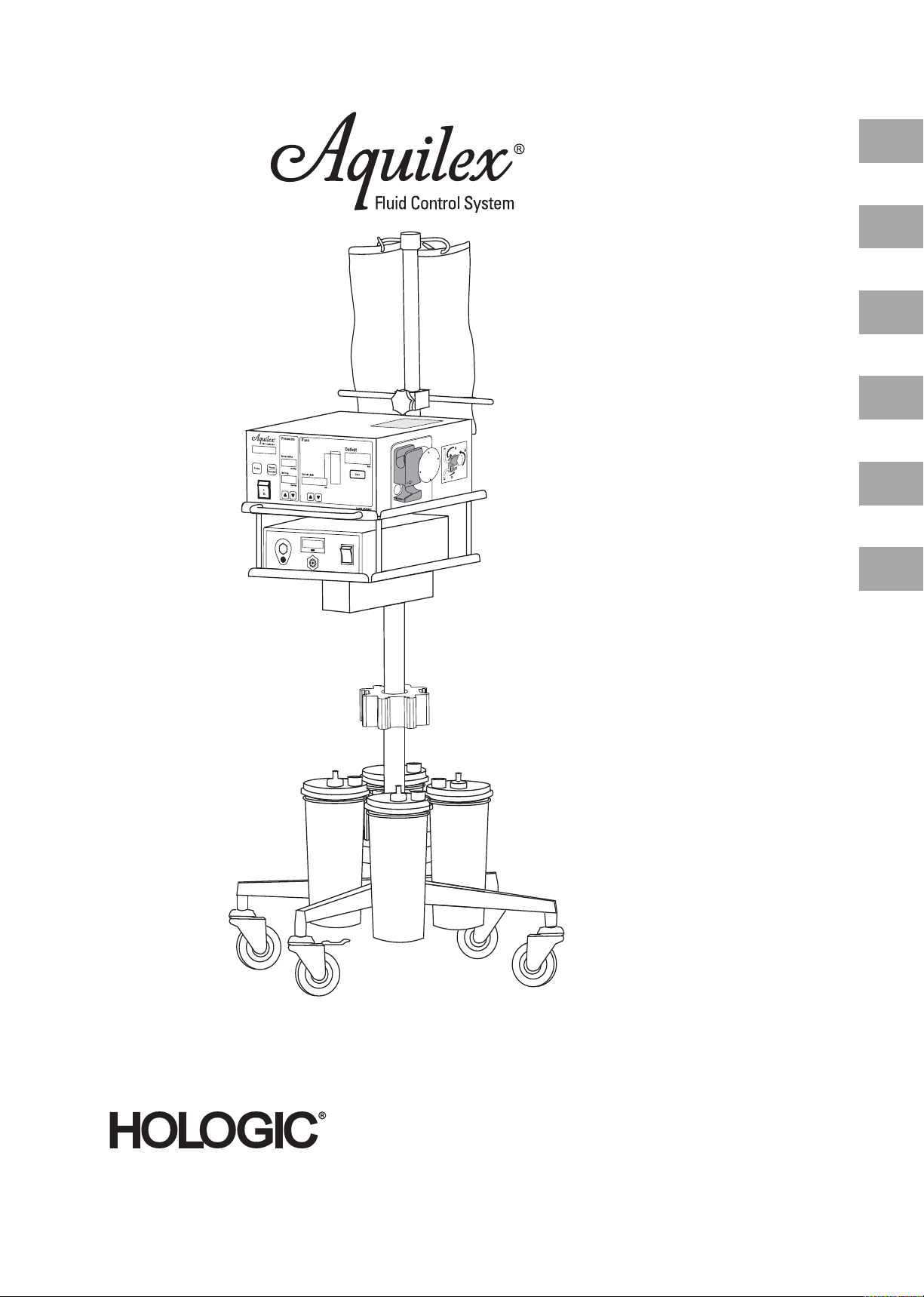
Instructions for Use and Fluid
Control System Operator’s Manual
Gebrauchs- und Bedienungsanweisungen für Fluid Control System
EN
DE
Manuel d‘instruction et d‘utilisation du
Fluid Control System
Manual de Instrucciones y de Utilización
del Fluid Control System
Istruzioni per l'uso e istruzioni operative
del Fluid Control System
Gebruiks- en bedieningsinstructies voor
Fluid Control System
FR
ES
IT
NL
Page 3
Hologic and MyoSure are registered trademarks of Hologic,
ENDEFRESIT
NL
Inc. and its subsidiaries in the United States and other countries. Aquilex is a trademark of Hologic, Inc. and its subsidiaries
in the United States and other countries. All other trademarks,
their respective owners.
zeichen, eingetragene Warenzeichen und Produktnamen sind Eigentum der
jeweiligen Inhaber.
spectifs.
ductos son propiedad de sus respectivos dueños.
registered trademarks, and product names are the property of
Hologic und MyoSure sind eingetragene Warenzeichen der Hologic, Inc. und ihrer Tochtergesellschaften in den Vereinigten
Staaten und anderen Ländern. Aquilex ist ein Warenzeichen
der Hologic, Inc. und ihrer Tochtergesellschaften in den Vereinigten Staaten und anderen Ländern. Alle anderen Waren-
Hologic et MyoSure sont des marques déposées de Hologic
Inc., de ses filiales aux États-Unis et d'autres pays. Aquilex est
une marque de Hologic Inc., de ses filiales aux États-Unis et
d'autres pays. Toutes les autres marques, marques déposées,
et noms de produits sont la propriété de leurs propriétaires re-
Hologic y MyoSure son marcas comerciales registradas de Hologic, Inc. y sus subsidiarias en los Estados Unidos y otros países.
Aquilex es una marca comercial de Hologic, Inc. y sus subsidiarias en los Estados Unidos y otros países. Todas las demás marcas
comerciales, marcas comerciales registradas y nombres de pro-
Hologic e MyoSure sono marchi registrati di Hologic, Inc. e relative società affiliate negli Stati Uniti e in altri paesi. Aquilex è
un marchio registrato di Hologic, Inc. e relative società affiliate
negli Stati Uniti e in altri paesi. Tutti gli altri marchi commer-
rispettivo proprietario.
gedeponeerde handelsmerken en productnamen zijn eigendom van de desbetreffende houders.
ciali, marchi registrati e nomi di prodotti sono di proprietà del
Hologic en MyoSure zijn gedeponeerde handelsmerken van
Hologic, Inc. en haar dochtermaatschappijen in de Verenigde
Staten en andere landen. Aquilex is een handelsmerk van Hologic, Inc. en haar dochtermaatschappijen in de Verenigde Staten en andere landen. Alle andere handelsmerken,
Manufacturer/Hersteller/Fabricant/Fabricante/
Fabbricante/Fabrikant:
W.O.M. WORLD OF MEDICINE GmbH
Salzufer 8
10587 Berlin, Germany
Phone: +49 30 39981-550
Fax: +49 30 39981-545
E-mail: info.berlin@womcorp.com
W.O.M. WORLD OF MEDICINE GmbH
Alte Poststraße 11
96337 Ludwigsstadt, Germany
Phone: +49 9263 877-0
Fax: +49 9263 877-152
E-mail: info.ludwigsstadt@womcorp.com
CE marking according to Directive 93/42/EEC
CE-Kennzeichnung gemäß Richtlinie 93/42/CEE
Marquage CE conforme à la directive 93/42/CEE
Identificación CE conforme a la directiva 93/42/CEE
Marchio CE conforme alla direttiva 93/42/CEE
EG-markering conform Richtlijn 93/42/EEG
Distributor/Vertreiber/Distributeur/Distribuidor/
Distributore/Distributeur:
HOLOGIC, INC.
250 Campus Drive,
Marlborough
MA 01752 USA
1.800.442.9892 (US Toll Free)
1.508.263.2900
MAN-02570-4320 Rev.009
Model: H112/1201048/10000011593 07/2016-04/endefresitnl/marik
Page 4
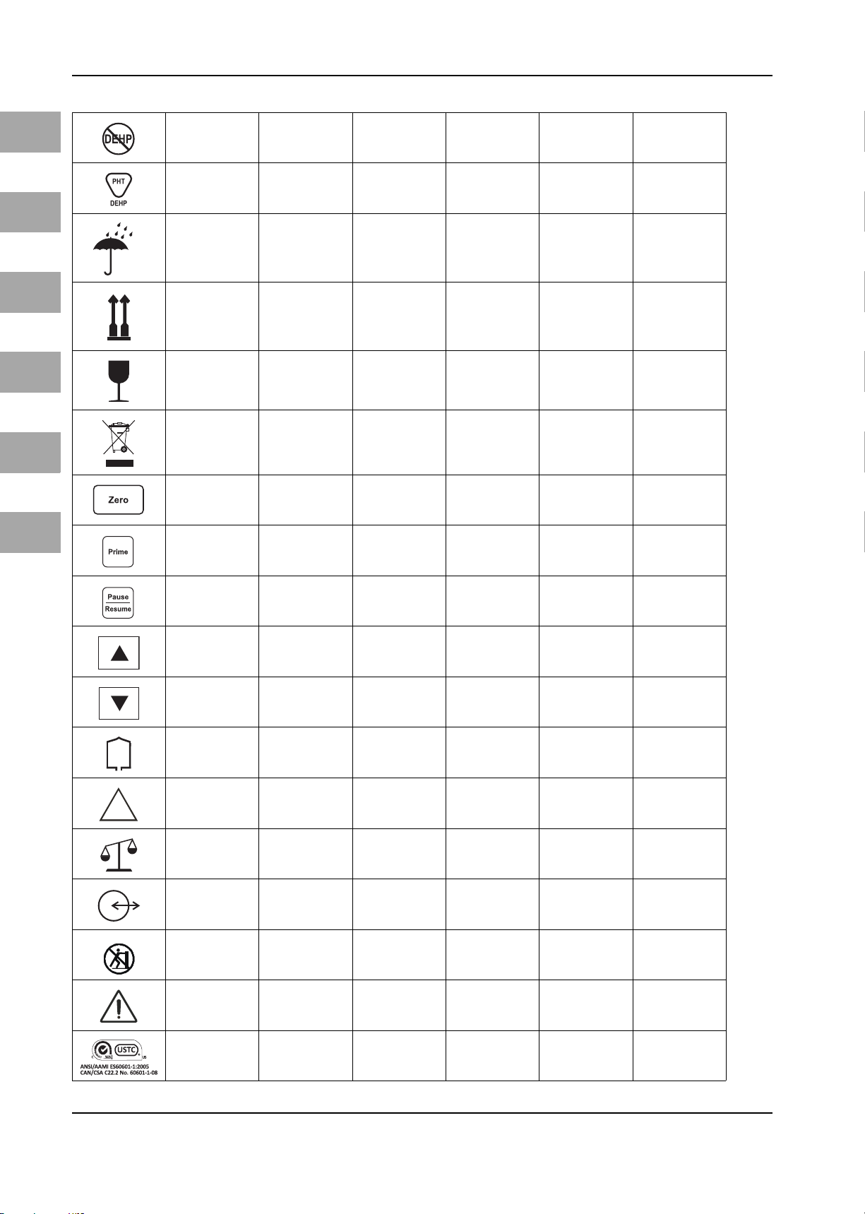
Symbols/Bildzeichen/Symboles/Símbolos/Simboli/Symbolen
EN
Read Instructions
Before Use
BF Type Equipment
Symbol for Poten-
tial Equalization
Degrees of Protec-
tion Provided by
Enclosures (IP-
Code)
Alternating Current
Service Service
Order Number
Bedienungsanlei-
tung befolgen
System des Typs BF
Symbol für Potenti-
alausgleich
Gehäuseschutz-
klasse (IP-Code)
Wechselstrom
Bestellnummer
Lire la documenta-
tion jointe !
Système de type BF
Symbole pour la
fiche équipoten-
tielle
Degrés de protec-
tion procurés parles
enveloppes (Code
IP)
Courant alternatif Corriente alterna Corrente alternata Wisselstroom
Service Servicio Servizio Service
Numéro de
commande
Observe la docu-
mentación adjunta
Sistema del tipo BF Sistema tipo BF
Símbolo para la
conexión equipo-
tencial
Grado de protec-
ción proporcio-
nado por los
envolventes
(Código IP)
Número de pedido
Leggere la docu-
mentazione alle-
gata
Simbolo per il colle-
gamento equipo-
tenziale
Grado di prote-
zione degli involu-
cri (Codice IP)
Numero di ordina-
zione
Lees de begelei-
dende documenta-
tie
Syteem van het
type BF
Symbool voor de
potentiaalvereffe-
ning
Beschermings-
klasse (IP-code)
behuizing
Bestelnummer
DE
FR
ES
IT
NL
Do not Reuse
Sterilized using
Ethylene Oxide
Lot Number
Serial Number
Date of Manufac-
ture
Expiration Date
Pieces
Quantity
Not Made with
Natural Rubber
Latex
Nicht zur Wieder-
verwendung
Sterilisiert mit
Ethylenoxid
Chargenbezeich-
nung
Seriennummer
Herstellungsdatum
Ver wendb ar bis
Stück
Menge
Nicht aus Natur-
kautschuklatex
hergestellt
Usage unique No reutilizable Non riutilizzabile
Stérilisés à l’éthy-
lène oxide
Numéro de lot Número de lote Numero di lotto Chargenummer
Numéro de série Número de serie Numero di serie Serienummer
Date de fabrication
Date limite
d’utilisation
Unités Unidades Pezzi Eenheden
Quantité Cantidad Quantità Hoeveelheid
Ce produit ne con-
tient pas de latex
de caoutchouc
naturel
Esterilizado con
óxido de etileno
Fecha de fabrica-
ción
Utilizable hasta
Producto no produ-
cido con látex de
caucho natural
Sterilizzato con
ossido di etilene
Data di produzione Fabricagedatum
Da utilizzarsi entro
il
Non prodotto in lat-
tice di caucciù
naturale
Niet voor herge-
bruik
Sterilisatie met
ethyleenoxide
Te gebruiken tot
Niet vervaardigd
van natuurlijke rub-
berlatex
Page 5
Symbols/Bildzeichen/Symboles/Símbolos/Simboli/Symbolen
NON
STERILE
FR
ES
IT
EN
DE
Not Made with
Phthalates
Made with Phthala-
tes
Do Not Get Wet
Top-Bottom
Fragile
Waste Manage-
ment
Reset Deficit
Button
Dieses Produkt enthält kein Diethylhe-
xylphthalat (DEHP)
Dieses Produkt ent-
hält Diethylhe-
xylphthalat (DEHP)
Vor Nässe schützen
Oben-Unten
Zerbrechlich
Entsorgung
Tas te Res et D ef ici t
Ce produit ne con-
tient pas du
diethylhexyl phta-
late (DEHP)
Ce produit contient
du diethylhexyl
phtalate (DEHP)
Protéger de l’humi-
dité
Haut-bas Arriba-abajo Alto - basso Boven-Beneden
Fragile Frágil Fragile Breekbaar
Élimination des
déchets
Touche de remise à
zéro du déficit
Este producto no
contiene dietilhe-
xilftalato (DEHP)
Este producto con-
tiene dietilhexilfta-
lato (DEHP)
Proteger contra la
humedad
Gestión de residuos Smaltimento Verwijdering
Tecla de reseteo del
déficit
Questo prodotto
non contiene
diethylhexylftalato
(DEHP)
Questo prodotto
contiene
diethylhexylftalato
(DEHP)
Proteggere
dall'umidità
Tasto di reset per
deficit
Dit product bevat
geen di-ethylftalaat
Dit product bevat
di-ethylftalaat
Beschermen tegen
Resettoets voor
(DEHP)
(DEHP
vocht
deficit
NL
Prime Button Taste Prime Touche Prime Tecla Prime Tasto Prime Toets Prime
Pause/Resume
Button
Increase
Decrease Verringern Décroissant Disminución Decrescente Verlagen
Fluid Bags Flüssigkeitsbeutel Poche de liquide Bolsa de líquido Sacche di liquido Vloeistofzak
Non-Sterile Nicht steril Non stérile No estéril Non è sterile Niet steriel
Connection for
Canister Scale
Data Transfer Datenübertragung
Tas t e
Pause/Resume
Erhöhen
Anschluss Contai-
newaage
Touche Pause/
Resum e
Croissant Aumento Crescente Verhogen
Raccord pour unité
de pesage à
container
Tra nsm iss ion d e
données
Tecla Pause/
Resum e
Conexión para la
balanza de cubetas
Transmisión de
datos
Tasto Pause/
Resume
Attacco per unità di
pesatura conteni-
tori
Trasmissione dati Datatransmissie
Aansluiting reservoirweegsysteem
Toets Pause/
Resume
Do not push! Schieben verboten Interdit de pousser! ¡No empujar! Non spingere! Duwen verboden
General Warning
Sign
SGS USTC Certifica-
tion Mark
Warnzeichen für
allgemeine Gefahr
SGS USTC Produkt-
zertifizierung
Signalisation
générale de danger
Marque de certifi-
cation SGS USTC
Señal de adverten-
cia general
Marca de certifica-
ción SGS USTC
Segnale generale di
pericolo
Marquio de certifi-
cazione SGS USTC
Waarschuwingsteken voor algemeen
gevaar
Kwaliteitsmerk SGS
USTC
Page 6

Table of contents
1 Important User Notes......................................................................................................................................................... 3
2 Safety Information.............................................................................................................................................................. 4
3 Purpose of the System ........................................................................................................................................................ 5
3.1 Warnings and Precautions .................................................................................................................................................... 5
3.1.1 Warnings .................................................................................................................................................................................... 5
3.1.2 Precautions................................................................................................................................................................................. 9
3.2 Description of the Aquilex Fluid Control System ............................................................................................................ 10
4 Initial System Set-up........................................................................................................................................................... 11
4.1 Preparing the System For Use............................................................................................................................................... 11
4.2 System Set-up............................................................................................................................................................................ 12
5 System Operation ............................................................................................................................................................... 13
5.1 Front of Pump............................................................................................................................................................................ 13
5.2 Rear of Pump.............................................................................................................................................................................. 13
5.3 Cart/scale.................................................................................................................................................................................... 14
5.3.1 Scale Set-up................................................................................................................................................................................ 15
5.3.2 Connecting the Vacuum Tubing........................................................................................................................................... 16
5.4 Turning On the Aquilex System............................................................................................................................................ 17
5.5 Hanging the Fluid Bags........................................................................................................................................................... 18
5.6 Using Tube Sets......................................................................................................................................................................... 18
5.7 Tubing Overview....................................................................................................................................................................... 19
5.8 Connecting the Outflow Tubing .......................................................................................................................................... 19
5.8.1 MyoSure® Outflow Connection............................................................................................................................................ 20
5.9 Inserting the Inflow Tube Set................................................................................................................................................ 21
5.10 Presetting the Intrauterine Pressure .................................................................................................................................. 22
5.11 Setting the Deficit Limit ......................................................................................................................................................... 22
5.12 Using the Pump during Operation...................................................................................................................................... 23
5.13 Changing Canisters during Procedure ............................................................................................................................... 23
5.14 Total Volume Displayed .......................................................................................................................................................... 24
5.15 Turning System Off.................................................................................................................................................................. 24
6 Safety functions .................................................................................................................................................................. 25
7 Care and Maintenance........................................................................................................................................................ 26
7.1 Cleaning the System................................................................................................................................................................ 26
7.2 Authorized Service Technician Maintenance................................................................................................................... 26
7.3 Replacing the Fuse ................................................................................................................................................................... 26
8 Annual Inspection............................................................................................................................................................... 28
8.1 Safety Test................................................................................................................................................................................... 28
8.2 Basic Function Tests................................................................................................................................................................. 28
8.3 Scale Test..................................................................................................................................................................................... 28
8.4 Flow Rate Test............................................................................................................................................................................ 29
8.5 Pressure Measuring Test ........................................................................................................................................................ 30
8.6 Fluid Deficit Measurement Test ........................................................................................................................................... 31
8.7 Vacuum Pump Operational Test........................................................................................................................................... 32
9 Error and Warning Messages.............................................................................................................................................. 33
10 Technical Data..................................................................................................................................................................... 35
11 Guidelines and manufacturer's statement - electromagnetic compatibility .................................................................... 37
11.1 Impact of Mobile and Portable HF Communication Devices....................................................................................... 37
11.2 Electrical Connections............................................................................................................................................................. 37
11.3 Guidelines and Manufacturer’s Statement – Electromagnetic Emissions.............................................................. 38
11.4 Guidelines and Manufacturer's Statement - Electromagnetic Interference Immunity....................................... 39
11.5 Guidelines and Manufacturer's Statement - Electromagnetic Interference Immunity....................................... 40
11.6 Recommended safety distances between portable and mobile HF telecommunications devices and the
Aquilex Fluid Control System................................................................................................................................................ 41
12 Accessory List ...................................................................................................................................................................... 42
13 Warranty Information ........................................................................................................................................................ 43
14 Glossary............................................................................................................................................................................... 45
15 Appendix ............................................................................................................................................................................. 46
15.1 Test Log........................................................................................................................................................................................ 46
Index.................................................................................................................................................................................... 47
EN
1
Page 7

Page 8
1Important User Notes
Read the manual carefully and become familiar with the operation and function
of the Aquilex® Fluid Control System (Aquilex System) and the accessories before
use during surgical procedures. Non-observance of the instructions listed in this
manual can lead to:
• life-threatening injuries to the patient,
• severe injuries of the surgical team, nursing staff or service personnel, or
• damage or malfunction of the system and/or accessories.
technical data of the product through continued development of the product.
sections with special attention.
WARNING!
Warnings indicate risks to the safety of the patient or user. Failure to follow
warnings may result in injury to the patient or user.
CAUTION!
Warnings indicate risks to the equipment. Failure to follow cautions may result
in damage to the system.
Important User Notes
EN
Subject to technical changesThe manufacturer reserves the right to modify the appearance, graphics, and
Please noteThe words WARNING, CAUTION, and NOTE carry special meanings. Read these
NOTE!
Notes provide special information to clarify instructions or present additional in-
formation.
3
Page 9

EN
Safety Information
2 Safety Information
Federal Law (only for U.S. market) Caution: Federal law restricts this device to sale by or on the order of a physician.
Exclusion of liability Hologic is not liable for direct or consequential damage and the warranty is null
and void if:
• the system and/or the accessories are improperly used, prepared, or maintained,
• the instructions in the manual are not adhered to,
• non-authorized persons perform repairs, adjustments, or alterations on or to
the system or accessories,
• non-authorized persons open the pump housing,
• the prescribed inspection and maintenance schedules are not adhered to.
Receipt of technical documentation from Hologic does not authorize individuals
to perform repairs, adjustments, or alterations on or to the system or accessories.
Authorized service technician Only an authorized service technician may perform repairs, adjustments, or al-
terations on the system or accessories. Any violation will void the manufacturer's
warranty. Authorized service technicians are trained and certified only by the
manufacturer.
Intended use The system may be used only as intended.
Care and maintenance The service and maintenance of the system and its accessories has to be carried
out as per instructions to ensure its safe operation. For the protection of the patient and the operating team, check that the system is complete and functional
before each use.
Waste management In the European Community, this symbol indicates that the waste of electrical
and electronic equipment must not be disposed of as unsorted municipal waste
and must be collected separately instead. Please contact Hologic or an accordingly authorized disposal or waste management company for further information.
4
Page 10
3 Purpose of the System
us during diagnostic and operative hysteroscopy, and to monitor the volume differential between the irrigation fluid flowing into and out of the uterus.
py is contraindicated. See the operators manual of your hysteroscope for absolute and relative contraindications.
Relative contraindications to endometrial ablation:
Hysteroscopic endometrial ablation, whether by laser or electrosurgery, should
not be undertaken before adequate training, preceptorship, and clinical experience. Additionally, tissue sampling is required prior to destruction of the endometrium. The following are clinical conditions that can significantly complicate
hysteroscopic endometrial ablation:
• Adenomatous endometrial hyperplasia
•Uterine leiomyoma
• Severe adenomyosis
• Pelvic pain (subtle PID)
• Uterine anomalies
• Surgical skill (see above)
• Severe anemia
• Inability to circumnavigate the myoma (re: myoma size) - predominantly intramural myomas with small submucous components.
Purpose of the System
Indication for useAquilex® Fluid Control System is intended to provide liquid distension of the uter-
ContraindicationsThe system may not be used to introduce fluids into the uterus when hysterosco-
EN
3.1 Warnings and Precautions
3.1.1 Warnings
WARNING!
When performing monopolar hysteroscopic electrosurgery, the distension medium must be electrically non-conductive. Examples include glycine, sorbitol and
mannitol. Isotonic saline irrigation fluids may only be used when performing bipolar electrosurgical resective procedures.
WARNING!
The pressure should be kept as low as possible to allow for a sufficient intrauter-
ine distension and to reduce the forces that could allow fluid, ambient air, and/
or gas to enter the circulatory system.
WARNING!
Intrauterine distention is usually possible with pressure values between 35 to
70 mmHg. A pressure above 75 to 80 mmHg is required only in rare cases or if the
patient has an excessively high blood pressure.
WARNING!
When using the cart/scale, follow the exact operating instructions in this manu-
al.
WARNING!
Fluid overload
There is a risk of irrigation fluid reaching the circulatory system of the patient's
soft tissue by passing through the uterus. This can be affected by distention pres-
sure, flow rate, perforation of the uterine cavity and duration of the hystero-
5
Page 11
EN
Purpose of the System
scopic surgery. It is critical to closely monitor the input and outflow of the
distending liquid at all times.
WARNING!
Fluid deficit
The fluid left in the patient must be monitored. The deficit is the total amount of
fluid left in the patient or unaccounted for otherwise. Take notice of the measurement tolerance of the system (see Chapter 10, Technical Data). Estimating
the fluid volume remaining in the patient is the physician’s responsibility.
WARNING!
Fluid intake and output surveillance
Strict fluid intake and output surveillance should be maintained. If a low viscos-
ity liquid distention medium is used, intrauterine instillation exceeding 2 liters
should be followed with great care due to the possibility of fluid overload. If a
high viscosity fluid (e. g. Hyskon) is used, the use of more than 500 ml should be
followed with great care. See labeling for Hyskon for additional information.
WARNING!
Serum sodium concentration
It is also necessary to monitor the concentration of sodium in the blood of the pa-
tient to prevent electrolyte disturbances. Monitoring of the concentration of sodium in the blood must be performed by the physician and is not performed or
supported by the system.
WARNING!
The deficit display value is lost in case of a power loss or “brownout.”
WARNING!
Hyponatremia
Some distension fluids may lead to fluid overload and, consequently, hyponatre-
mia with its attending sequelae. This can be affected by the distending pressure,
flow rate, and duration of hysteroscopic procedure. It is critical to closely monitor the input and outflow of the distending liquid at all times.
WARNING!
Pulmonary edema
Hysteroscopic surgery is associated with a risk of developing pulmonary edema
resulting from fluid overload with isotonic fluids. It is critical to closely monitor
the input and outflow of the distending liquid at all times.
6
Page 12
Purpose of the System
WARNING!
Cerebral edema
Hysteroscopic surgery is associated with a risk of developing cerebral edema re-
sulting from fluid overload and electrolyte disturbances with hypoosmolar (nonionic) fluids such as glycine 1.5% and sorbitol 3.0%. It is critical to closely monitor
the input and outflow of the distending liquid at all times.
WARNING!
Idiosyncratic reactions
In rare cases, idiosyncratic reactions, including:
• intravascular coagulopathy
• allergic reaction including anaphylaxis
may occur while performing hysteroscopy if a liquid distention medium is used.
Specifically, idiosynatric anaphylactoid reactions have been reported when using Hyskon as an irrigation fluid during hysteroscopy. These should be managed
like any allergic reaction.
WARNING!
Hypothermia (monitoring body temperature)
Continuous flow of distention fluids can lead to a lowering of the patient's body
temperature during hysteroscopic surgery. Lower body temperatures can cause
coronary and cardiovascular problems. Always monitor the patient's body temperature during the entire surgery. Make especially sure that the following, hypothermia promoting, operation conditions are avoided as best as possible:
• longer operating times
• use of cold irrigation fluid.
EN
WARNING!
Rupture of the fallopian tube secondary to tubal obstruction
Distention of the uterus may lead to a tear of the fallopian tube should there be
an obstruction or permanent occlusion. The rupture could lead to irrigation fluid
flowing into the patient's peritoneal cavity, resulting in a fluid overload. It is critical to closely monitor the input and outflow of the distending liquid at all times.
WARNING!
An air embolism can be the result of air contained in the tube set or connected
instrument reaching the patient. Ensure there is always fluid in the bag to prevent air from being pumped into the patient.
WARNING!
The system is only intended for use with flexible fluid containers. Do not use
glass containers as they might break. With rigid containers, fluid cannot flow
quickly enough due to the vacuum being generated inside of the containers. Risk
of implosion with rigid containers.
WARNING!
Filling the tubing with irrigation fluid and resetting the deficit display to zero are
to be done at the physician’s discretion.
7
Page 13
EN
Purpose of the System
WARNING!
Place the system in such a way as to allow for easy visualization of the display
values, system functions, and access to the control elements.
WARNING!
Do not use this system if a defect is suspected or detected during the function
check. This also applies to obvious defects, especially defects and damage to the
power plug and power cord.
WARNING!
Pressing the ON/OFF switch does not disconnect the system from the wall power
outlet. This requires pulling the power cord located in the rear of the system.
WARNING!
Technique and procedures
Only the physician can evaluate the clinical factors involved with each patient
and determine if the use of this system is indicated. The physician must determine the specific technique and procedure that will accomplish the desired clinical outcome.
WARNING!
Check all factory settings.
Factory settings are not mandatory settings for the physician. The physician is responsible for all settings affecting the surgical procedure.
WARNING!
Original accessories
For your own safety and that of your patient, use only Aquilex accessories.
WARNING!
Not explosion-proof
The system is not explosion-proof. Do not use in an area where flammable anesthetic gases are present.
WARNING!
No modification of this equipment is allowed.
WARNING!
To avoid risk of electric shock, this equipment must only be connected to a sup-
ply mains with protective earth.
8
Page 14
WARNING!
Professional qualification
This manual does not include descriptions or instructions for surgical proce-
dures/techniques. It is also not suitable for training physicians in the use of surgical techniques. Medical instruments and systems may be used only by
physicians or medical assistants with the appropriate technical/medical qualification working under the direction and supervision of a physician.
WARNING!
Sterile media and accessories
Always work exclusively with sterile substances and media, sterile fluids, and
sterile accessories, if so indicated.
WARNING!
Replacement system and accessories
In case the system or any of the accessories fail during a procedure, an alterna-
tive system and replacement accessories should be kept within easy reach to be
able to finish the operation with the replacement components.
Purpose of the System
EN
WARNING!
Cleaning the system
Do not sterilize the system.
WARNING!
Condensation / Water penetration
Protect system from moisture. Do not use if moisture has penetrated the system.
WARNING!
System defect
If a system defect is suspected or confirmed, do not use the system. Ensure the
system will no longer be used until a qualified service technician conducts the
appropriate tests and repairs.
WARNING!
Replacing fuse
Replace the fuse only with a fuse of the same type and rating (see Chapter 10,
Technical Data).
WARNING!
Equipment should be positioned such that power cord can be easily disconnect-
ed.
3.1.2 Precautions
CAUTION!
Federal Law (only for U.S. market)
Federal law restricts this device to sale by or on the order of a physician.
9
Page 15
EN
Purpose of the System
CAUTION!
When using the Aquilex System with MyoSure® or other morcellation systems,
the combination of low set pressures and high vacuum pressures may result in a
significant loss of intrauterine distension pressure which has the potential to affect the visibility of the surgical field. Conversely, when employing high distension pressures, the deactivation of the MyoSure® or other morcellator system
can lead to pressure spikes that can exceed 150 mmHg. These situations may occur for a short time as the system automatically adjusts the flow rate to return
to the set intrauterine pressure.
CAUTION!
The system may only be connected with hysteroscopes designed for and featur-
ing the technical specification permitting such a combined use. Any utilized hysteroscopes must comply with the most recent versions of EC 60601-2-18 and
ISO 8600.
CAUTION!
Electrical Interference: (See Chapter 11, Guidelines and manufacturer's state-
ment - electromagnetic compatibility). Electrical interference with other devices
or instruments was practically eliminated when developing this system and
none was detected during testing. However, if you still detect or suspect such interference, please follow these suggestions:
• Move the Aquilex System, the other device, or both devices to a different location
• Increase distance between devices used
• Consult an electro-medical expert
CAUTION!
Check to ensure the available wall outlet voltage matches the data listed on the
label attached to the back of the pump. Incorrect voltage can cause errors and
malfunctions and may destroy the system.
3.2 Description of the Aquilex Fluid Control System
Technical application scope of the system The intrauterine pressure can be adjusted on the front of the pump. It can be pre-
set to a range between 40 and 150 mmHg. The maximun inflow rate is 800 ml/
min and is reduced automatically by the pump once the pre-set intrauterine
pressure setting has been reached.
The system has been designed to provide both fluid and vacuum systems that
maximize the performance of the MyoSure® Tissue Removal System.
Suggested distension media The Aquilex Fluid Control System can be used with hypotonic, electrolyte-free
media (e.g., glycine 1.5% and sorbitol 3.0%) and isotonic, electrolyte containing
media (e.g., saline 0.9% and Lactated Ringer's).
Pressure measuring and regulating The system operates with a completely non-contact pressure measurement of
the irrigation medium. The contact-free pressure measurement is achieved by integrating the pressure chamber into the tubing system. The pressure chamber
transmits the irrigation fluid pressure to the electronics of the device via a pressure sensor. The pressure control circuit continuously compares the desired preset intrauterine pressure with the actual intrauterine pressure. The function of
this algorithm is to maintain the pre-set intrauterine pressure. Check for possible
leaks if the pre-set intrauterine pressure cannot be achieved.
10
Page 16
4 Initial System Set-up
Always check all parts and accessories of the system when performing initial setup. If the system should show obvious defects, contact Hologic Technical Support
(Chapter 13, Warranty Information).
temperature and humidity must meet the requirements mentioned in Chapter
10, Technical Data.
WARNING!
Equipment should be positioned such that power cord can be easily disconnected.
4.1 Preparing the System For Use
CAUTION!
Check to ensure the available wall outlet voltage matches the data listed on the
label attached to the back of the system. Incorrect voltage can cause errors and
malfunctions and may destroy the system.
Initial System Set-up
EN
Initial system set-upPlace the system on a level surface and install in a dry environment. The ambient
Connection to the wall outlet
Ensure the connection data and technical specifications of the power supply
comply with DIN VDE or national requirements. The wall outlet power supply
cord must be plugged into a properly installed safety wall plug (see DIN VDE
0107). Read the device label located in rear of pump to determine the operating
voltage of the system.
The power connection must be equipped with a grounding contact. Use the Aquilex power cord to establish a connection between the wall outlet and the power
cord connection located in the rear of the system.
3 leads. The plug connectors must comply with NEMA 5-15 or IEC 320/CEE22.
Grounding will only be reliable if the equipment is connected to a corresponding
hospital grade outlet.
safety rules and regulations.
electromagnetic compatibility (hereafter abbreviated as EMC).
This system is to be used only for the purposes described in the manual and has
to be installed, set up, and operated in compliance with the EMC notes and instructions.
Grounding contact
Only for U.S. operatorsUse only a certified (UL-listed), removable power cord, type SJT, minimal 18 AWG,
Potential equalizationIntegrate the system into the potential equalization system as specified by local
Precautionary measuresMedical devices are subject to special safety and protective measures concerning
11
Page 17

EN
(10)
(5)
(7)
(8)
(11)
(1)
(9)
(12)
(4)
(2)
(3)
(6)
Initial System Set-up
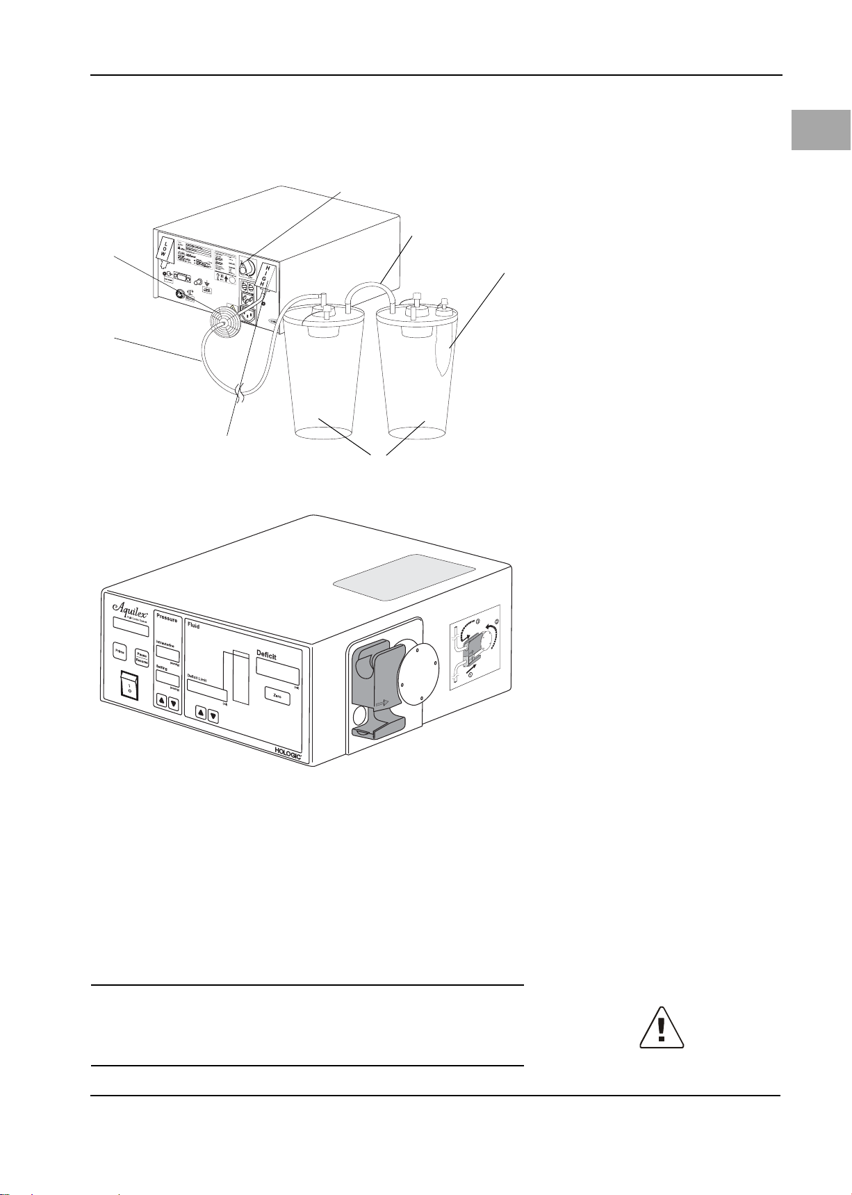
4.2 System Set-up
Figure 4-1 Set-up of Aquilex Fluid Control
System
(1) Cart
(2) Bag holder
(3) Pump
(4) Fluid bag
(5) Tr ay s
(6) Scale cable
(7) MyoSure® Control Unit
(8) Scale
(9) Canister holders
(10) Canister
(11) Roller base
(12) Locking foot brake
The Aquilex Fluid Control System is divided into two separate boxes for shipping.
Box 1 contains:
•Pump
•Manual
• Wall power cord
• Aquilex vacuum tube set (low and high vacuum)
• MyoSure® Control Unit power cord
Box 2 contains:
• Cart/scale
• Canister rings
12
Page 18

5System Operation
(11)
(1)
(2)
(3)
(7)(4)
(5)
(6)
(8)
(9)
(10)
(13)
(16)
(17)
(15)
(14)
(12)
(6)
(5)
(4)
(9)
(1)
(2)
(3)
(7)
(8)
(10)
(11)
(12)
(12)
5.1 Front of Pump
Please familiarize yourself with the layout of the individual elements on the front
of the pump.
5.2 Rear of Pump
System Operation
EN
Fig. 5-1 Front of Pump
(1) Pump display
(2) Intrauterine pressure display
(3) Fluid deficit limit display
(4) Deficit meter
(5) Deficit display
(6) Inflow tube holder
(7) Roller wheel
(8) Pressure sensor
(9) Reset deficit button (Zero)
(10) Decrease deficit limit
(11) Increase deficit limit
(12) Decrease intrauterine pressure set-
ting
(13) Increase intrauterine pressure set-
ting
(14) Intrauterine pressure setting dis-
play
(15) ON/OFF switch
(16) Pause/Resume button
(17) Prime button
Please familiarize yourself with the layout of the individual elements at the rear
of the pump.
CAUTION!
Any devices to be connected via the interface have to comply with EN 60950.
Figure 5-2 Rear of Pump
(1) Low vacuum port (white)
(2) Product ID label
(3) Device performance data
(4) Adjustment dial for high vacuum
(5) High vacuum port (green)
(6) Fuse holder(s)
(7) Power cord connection
(8) MyoSure® Control Unit Power Con-
nection
(9) Potential equalization connector
(10) Service interface
(11) Scale connection
(12) Exhaust ports
13
Page 19

EN
(1)
(3)
(6)
(7)
(4)
(8)
(5)
(9)
(2)
System Operation
5.3 Cart/scale
Figure 5-3 Cart/Scale
(1) Fluid bag
(2) Scale cable
(3) Scale
(4) Pole with bag hooks
(5) Bag deflector
(6) Canister
(7) Upper canister holder (Serres,
Medela, Baxter, Baxter flex)
(8) Lower canister holder (Abbott,
Bemis, Medi-Vac, DeRoyal)
(9) Roller base
The cart/scale consists of a weighing scale for the canisters, a pole with hooks for
irrigation fluid bags, and a roller base.
1. Remove the cart/scale from the cardboard shipper box.
2. Extend the pole to stop position.
3. Extend the bag deflector to stop position.
4. Remove the pump and the power cords from the first cardboard box.
5. Install canister rings (included in the second box) on upper (7) or lower (8)
canister holders, in accordance with type of canister.
6. Connect the wall power cord to the male outlet at the rear of the pump ((7)
Figure 5-2, Rear of Pump, page 13) and a grounded safety wall outlet.
7. Connect the scale to the pump by connecting the scale cable ((2) Figure 5-3,
Cart/Scale) to the scale connection ((11) Figure 5-2, Rear of Pump).
8. Use the enclosed MyoSure Control Unit power cord to connect the pump ((8)
Figure 5-2, Rear of Pump) with the MyoSure® Control Unit.
WARNING!
Scale error
Ensure that nothing weighs down the scale during system start-up. Doing so
may result in an inaccurate deficit value.
WARNING!
Fluid deficit
The fluid left in the patient must be monitored. The deficit is the total amount of
fluid left in the patient or unaccounted for otherwise. Take notice of the measurement tolerance of the system (see Chapter 10, Technical Data). Estimating
the fluid volume remaining in the patient is the physician’s responsibility.
14
Page 20

WARNING!
Serum sodium concentration
It is also necessary to monitor the concentration of sodium in the blood of the pa-
tient to prevent electrolyte disturbances. Monitoring of the concentration of sodium in the blood must be performed by the physician and is not performed or
supported by the system.
to achieve the most exact deficit value possible.
value triggers the Scale Overloaded/Check Scale message. Three audible warning
tones are emitted (See Chapter 9, Error and Warning Messages.)
CAUTION!
Ensure canisters hang freely and are not supported or in contact with anything;
otherwise, the deficit calculated is inaccurate.
NOTE!
Connect the scale to the pump before turning the system on to ensure the sys-
tem recognizes the scale.
System Operation
EN
Precise balancingTry to collect all the fluid running out of the uterine cavity during the procedure
Scale capacityThe scale can be loaded with a weight of up to 65 lbs (~30 kg). Weight above this
5.3.1 Scale Set-up
The scale can be equipped with different makes of canisters.
Bemis®3 liters DeRoyal®
Abbott 2 liters Serres 2 & 3 liters
Medi-Vac® 3 liters Medela 3 liters
15
Page 21

System Operation
(3)
(4)
(2)
(1)
(5)
EN
Medi-Vac Flex Advantage
3000 cc
NOTE!
Ensure canisters are positioned properly in the respective holders.
NOTE!
Only use canisters with overflow protection.
5.3.2 Connecting the Vacuum Tubing
CAUTION!
When using the Aquilex System with MyoSure® or other morcellation systems,
the combination of low set pressures and high vacuum pressures may result in a
significant loss of intrauterine distension pressure which has the potential to affect the visibility of the surgical field. Conversely, when employing high distension pressures, the deactivation of the MyoSure® or other morcellator system
can lead to pressure spikes that can exceed 150 mmHg. These situations may occur for a short time as the system automatically adjusts the flow rate to return
to the set intrauterine pressure.
Figure 5-4 Low vacuum tube
(1) Low vacuum port (white)
(2) Hygiene filter
(3) Vacuum tube
(4) Canisters
(5) Tandem tu be
1. Connect vacuum to the suction containers (using vacuum tube with hygiene
filter). This is done once during the initial set-up of the system, not prior to
each procedure.
• Low Vacuum Side (White)
· Connect vacuum tube with white connectors to low vacuum port (1) Fig-
ure 5-4. This vacuum pump has a fixed vacuum pressure (~ 225 mmHg).
· Use tandem tube ((5) Figure 5-4, Low vacuum tube) when two canisters
are serially connected to the same vacuum port.
• High Vacuum Side (Green)
· Connect vacuum tube set with the green connectors to the high vacuum
port (green)
(8) in Figure 5-5. This vacuum can be adjusted to a maximum
16
Page 22
500 mmHg using adjustment dial.
(7)
(8)
(9)
(6)
(10)
(11)
(12)
· Use tandem tube ((12) Figure 5-5, High vacuum tube) when two canisters
are serially connected to the same vacuum port.
System Operation
EN
Figure 5-5 High vacuum tube
(6) Hygiene filter
(7) Vacuum tube (green connectors)
(8) High vacuum port (green)
(9) Canisters
(10) Tissue trap (MyoSure® procedures)
(11) Adjustment dial
(12) Tan dem tube
5.4 Turning On the Aquilex System
1. Press the ON/OFF switch. The displays and indicators light up and system
turns on.
2. The system now performs a self-diagnostic test.
3. If a tube set is in the inflow tube holder when the pump switches on, the
pump display (Fig. 5-1, Front of Pump (1)) shows Remove Tube Set. The selftest resumes once the tube set is removed from the roller wheel.
If the system self-test is unsuccessful, the corresponding error messages are
displayed. (See Chapter 9, Error and Warning Messages).
The system has successfully completed the self-diagnostic test when a single audible tone is heard. The message System OK is displayed for 5 secs followed by
the message Insert Tube Set.
WARNING!
Do not use this system if a defect is suspected or detected during the function
check. This also applies to any obvious defects, especially defects on the power
plug and power cord.
17
Page 23

EN
(2)
(1)
(3)
System Operation
5.5 Hanging the Fluid Bags
Figure 5-6 Fluid bag suspension
(1) Fluid bags
(2) Pole with bag hooks
(3) Bag deflector
WARNING!
When performing monopolar hysteroscopic electrosurgery, the distension medium must be electrically non-conductive. Examples include glycine, sorbitol and
mannitol. Isotonic saline irrigation fluids may only be used when performing bipolar electrosurgical resective procedures.
Hang one or two fluid bags with distension media appropriate for procedure. (A
MyoSure® procedure utilizes one or two 3000 cc saline bags.)
WARNING!
The system is only intended for use with flexible fluid containers. Do not use
glass containers as they might break. With rigid containers, fluid cannot flow
quickly enough due to the vacuum being generated inside of the containers. Risk
of implosion with rigid containers.
5.6 Using Tube Sets
The Aquilex Fluid Control System is designed for use with disposable inflow and
outflow tube sets.
Tube set recognition technology Each inflow tube set is equipped with tube set recognition technology. An RFID
transponder detects the type of tubing, whether it has been used, and its reliability automatically. The pump display indicates this information. This eliminates
accidental reuse of tubing on more than one patient (see Chapter 5.7, Tubing
Overview).
WARNING!
Reprocessing of sterile disposable products
Reuse of inflow or outflow tubing can cause an infection hazard for patients
and/or users as well as impair of product functionality. Contamination and/or
impaired functionality of the system can cause risk of injury, illness, or death. Do
not re-process single-use inflow or outflow tubing.
18
NOTE!
Comply with hygiene rules when disposing of tubing, fluid collected, and the
canisters.
Page 24

5.7 Tubing Overview
(2)
(6)
(3)
(4)
(5)
(1)
(7)
(5)
(3)
(1)
Three different tube sets are necessary to operate the system. The following table lists each type of tube set and its application.
Part Number Description
AQL-110 Aquilex Fluid Control System Inflow Tube Set
AQL-111 Aquilex Fluid Control System Outflow Tube Set
AQL-112 Complete tube set (Inflow and Outflow) disposable, sterile
AQL-114 Aquilex Fluid Control System High and Low Vacuum Tube
Set: re-usable, non-sterile
Table 5- 1
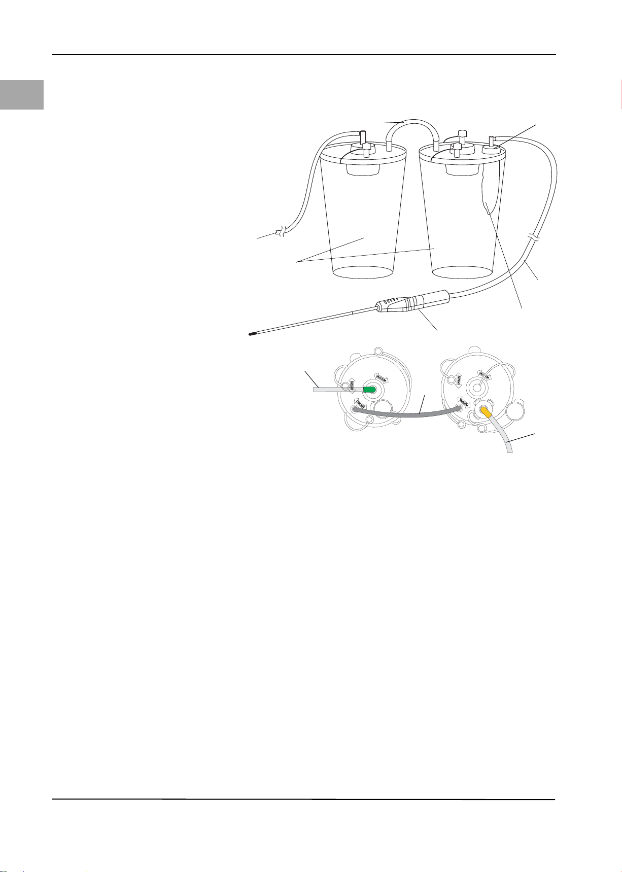
5.8 Connecting the Outflow Tubing
CAUTION!
When using the Aquilex System with MyoSure® or other morcellation systems,
the combination of low set pressures and high vacuum pressures may result in a
significant loss of intrauterine distension pressure which has the potential to affect the visibility of the surgical field. Conversely, when employing high distension pressures, the deactivation of the MyoSure® or other morcellator system
can lead to pressure spikes that can exceed 150 mmHg. These situations may occur for a short time as the system automatically adjusts the flow rate to return
to the set intrauterine pressure.
System Operation
EN
Figure 5-7 Outflow Tubing
(1) To low vacuum port (white)
(2) Canisters
(3) Tande m tube
(4) Patient port
(5) Outflow tube set
(6) Drape
(7) Removable Outflow Channel (Myo-
Sure®) or hysteroscope outflow
sheath stopcock
Using Low Vacuum configuration of Figure 5-4, connect outflow tubing (Y-tube)
to patient port (4) of second canister. Yellow flexible connector attaches to
drape (6). Yellow luer fitting connects to stopcock (7) of Removable Outflow
19
Page 25
System Operation
(7)
(6)
(3)
(4)
(5)
(1)
(2)
(6)
(3)
(1)
Channel (MyoSure®) or hysteroscope outflow sheath.
EN
5.8.1 MyoSure® Outflow Connection
Figure 5-8 MyoSure®Connection
(1) To High Vacuum port (green)
(2) Canisters
(3) Tande m tube
(4) Specimen tissue port
(5) Tissue trap
(6) MyoSure® vacuum tube
(7) MyoSure® Tissue Removal Device
(TRD)
If intrauterine pathology is identified, the MyoSure® TRD can be connected to the
Aquilex System as shown in Figure 5-8. The MyoSure® vacuum tube (6) is connected to the tissue trap (5) located in the second canister.
20
Page 26

5.9 Inserting the Inflow Tube Set
(7)
(5)
(8)
(1)
(2)
(4)
(3)
(9)
(6)
(10)
1
2
3
(9)
(8)
(3)
(2)
(5)
(7)
(1)
(6)
System Operation
EN
Figure 5-9 Tube set elements
(1) Protective caps
(2) Bag spikes
(3) Tubing clamps
(4) Y-connector
(5) Inflow section
(6) Roller wheel section
(7) Pressure chamber with membrane
and RFID transponder
(8) Hysteroscope section
(9) Luer lock connector (blue)
(10) Roller wheel connector
(See Figure 5-9, Tube set elements) The inflow tube set consists of three tube sections, a Y-connector (4) and two bag spikes (2). The three tube sections are: roller wheel section (6), inflow section (5), and hysteroscope section (8).The bag
spikes (2) are used to connect the tube sections to the bags.
The Luer lock connector (9) connects the hysteroscope tube with the hysteroscope.
Figure 5-10 Inserting the tube set
(1) Bag spikes
(2) Fluid bags
(3) Bag clamps
(5) Inflow tube
(6) Roller wheel tube
(7) Pressure chamber with mem-
brane and RFID transponder
(8) Hysteroscope tube
(9) Luer lock connector (blue)
Open outer packaging of the inflow tube set.
A sterile nurse then removes the inner tube set package and opens it.
Keep the blue Luer lock connector (9) in the sterile area and hand the tube
end with the bag spikes (1) to the non-sterile nurse.
Open outer packaging1. Inflow tube set - To be carried out by non-sterile nurse:
Connect to hysteroscope2. To be carried out by sterile nurse:
21
Page 27

EN
(5)
(6)
(7)
(11)
(8)
(12)
(13)
System Operation
Connect the blue Luer lock connector (9) with the hysteroscope inflow stop-
cock. Open stopcock.
Insert tube set 3. To be carried out by non-sterile nurse:
Ensure system is turned on.
Close the clamps (3) on the inflow tubing below the bag spikes (1).
Insert the inflow tube set into the inflow tube holder.
Insertion of the roller wheel tube is depicted in Figure 5-11, Positioning the
roller wheel tube.
Carefully insert the pressure chamber (7) into the lower notch of the inflow
tube holder (12) until you feel resistance. Align pressure chamber and inflow
tube holder using arrows (see Figure 5-11, Positioning the roller wheel tube).
When inserting the roller wheel tube, ensure not to damage the membrane
of the pressure chamber. Insert the pressure chamber (7) only if chamber is
not pressurized.
Place the roller wheel tube (6) around the roller wheel (11).
Connect the fluid bags
Figure 5-11 Positioning the roller wheel
tube
(5) Irrigation tube
(6) Roller wheel tube
(7) Pressure chamber
(8) Hysteroscope tube
(11) Roller wheel
(12) Inflow tube holder
(13) Alignment arrows
When connecting or removing the tube to or from the irrigation fluid bags,
grasp the bag spike at the provided handle. Observe aseptic technique when
inserting the spike(s) into the fluid bag(s). The surgeon must select a distension fluid suitable for the type of procedure.
5.10 Presetting the Intrauterine Pressure
Intrauterine pressure setting The intrauterine pressure setting can be adjusted while the system is in opera-
tion. Use the º and » buttons (Fig. 5-1, Front of Pump). The pressure setting can
be adjusted to between 40 to 150 mmHg in steps of 5 mmHg. The intrauterine
pressure is shown on the intrauterine pressure display (2).
Safety threshold When scrolling with the º button (Fig. 5-1, Front of Pump) if the safety threshold
of 100 mmHg is reached, an audible tone is emitted. Release the º button for one
second and scroll again to set higher values up to 150 mmHg.
CAUTION!
If the intrauterine pressure does not react to an increase in the pressure setting
during the procedure, a perforation of the uterine cavity might be the cause. This
results in an increased risk of intravasation. Examine the uterine cavity for injuries.
5.11 Setting the Deficit Limit
Deficit limit setting The deficit limit can be adjusted while the system is in operation. Use the º and
» buttons (Fig. 5-1, Front of Pump). The deficit limit can be adjusted to between
600 to 2500 ml in increments of 100 ml. The deficit limit is shown on the deficit
limit display (3). The deficit meter is designed to help the user track the deficit
volume. The color of the deficit meter changes as the deficit limit is approached.
The user set deficit limit is marked with a red LED on the top of the deficit meter.
22
Page 28

During the operation as the actual deficit climbs, the LEDs will light up sequentially representing the actual deficit volume until the deficit limit is reached. (See
Section Deficit Limit in Chapter 6, Safety functions).
5.12 Using the Pump during Operation
Open bag clamps ((3) Figure 5-10).
Fully open hysteroscope inflow stopcock.
Press the Prime button ((17) Fig. 5-1).
Pump will run for approximately 20 seconds to purge air from tubing and
run the Automatic Lumen Calibration.
Pump will display Calibration Running.
system determines the flow resistance of the hysteroscope. This resistance is
used to calculate the pump pressure necessary to maintain the pre-set intrauterine pressure. In order to overcome this resistance the pump allows pressure of up
to 80 mmHg during calibration. This is indicated in the Intrauterine Pressure display. In case calibration fails due to high resistance it will be repeated allowing
pressure of up to 150 mmHg. If it still cannot be completed the pump will show
Prime Fail -Open Stopcock, Clamps.
The automatic lumen calibration starts once the Prime button is pressed.
Once Automatic Lumen Calibration is completed, pump will beep three
times. The pump display will show Prime Successful Close Stopcock for 5 secs
followed by System Operating.
Close hysteroscope inflow stopcock to stop fluid flow. Once all fluid has been
removed from the drape, zero the deficit display.
System Operation
EN
Automatic lumen calibrationThe pump is equipped with an automatic lumen calibration functionality. The
NOTE!
The pump continues to operate after automatic lumen calibration is complete.
The pump should be stopped by closing hysteroscope inflow stopcock.
NOTE!
Automatic lumen calibration has to be performed each time a different hysteroscope is used during the procedure by pressing the Prime button.
Open stopcock and guide the hysteroscope with fluid flowing into the uter-
us.
Adjust intrauterine pressure setting as necessary to obtain adequate disten-
sion and visualization.
Wait until the entire fluid volume in the under-buttock drape and the tube
set has been has been collected into the canisters.
Press the Pause/Resume button.
Record the deficit volume on the deficit display. This is the total fluid volume
that was absorbed by the patient.
WARNING!
Device error: Do not use the Aquilex System if a defect is suspected or detected
during the function check. This also applies to obvious and visible defects, espe-
cially defects and damage of the power plug and power cord.
System Operation
Completing System Operation After system operation is complete, close the hysteroscope inflow stopcock.
5.13 Changing Canisters during Procedure
This locks the fluid deficit display number.
Remove desired canisters and install new canisters.
Changing canisters during the procedure Pause the pump by pressing Pause/Resume button.
23
Page 29

EN
System Operation
Reconnect canister tubing.
Press Pause/Resume button to resume procedure.
CAUTION!
If a filled canister is removed from scale without activating the " Pause/Resume"
button, the message "Container Change, Press Resume" will appear, the pump
will stop immediately and the deficit display locked to insure an accurate deficit
count is maintained. Once the canister exchange is completed, the System is restarted by pressing "Pause/Resume" button.
5.14 Total Volume Displayed
Total volume displayed If a manual check of fluid deficit is desired, the total fluid volume can be obtained
by simultaneously pressing and holding both the up and down arrows ((10) &
(11) in Fig. 5-1, Front of Pump) underneath the Fluid Deficit Limit display ((3) in
Fig. 5-1, Front of Pump). The number in the Deficit Display is the total fluid volume in ml. Once one or both of these buttons is released, the Deficit Display will
return to the Fluid Deficit value.
5.15 Turning System Off
Shut down Press the ON/OFF switch to tu rn pu mp of f. The d ispl ays and indicat ors are no lo n-
ger illuminated.
WARNING!
Pressing the ON/OFF switch does not disconnect the system from the wall power
outlet. This requires pulling the power cord located in the rear of the system.
24
Page 30

6 Safety functions
The electronic components continuously monitor the proper function of the system. System malfunctions are indicated with audible warning tones, error messages, and/or the blocking of system functions. A table listing a summary of
possible error and warning messages is provided in Chapter 9, Error and Warning
Messages.
Safety functions
EN
If the intrauterine pressure exceeds the intrauterine pressure setting by
10 mmHg for longer than 5 seconds, the pressure reduction function is activated.
The roller wheel will move forward or backward a few times during the pressure
reduction process. If the pressure cannot be reduced, the message Overpressure/
Open Stopcock is displayed and three audible tones are emitted.
tones once the intrauterine pressure exceeds 150 mmHg. The maximum permissible pressure has now been reached.
roller wheel stops and the message Overpressure/Check Stopcock is displayed.
Three short continuous audible warning tones are continuously emitted until the
pressure is reduced. Once the intrauterine pressure falls below 200 mmHg, the
audible alarm stops and the pump wheel resumes turning automatically.
Prime button results in a short audible tone and Check Tube Set Installation is
displayed. The roller wheel does not start to turn.
ror is displayed and five short audible tones are emitted. The roller wheel stops
turning.
tinuous audible tone is emitted and Scale Overloaded Check Scale is displayed.
The warning stops once the excess weight is removed from the scale.
Intrauterine pressure 10 mmHg above preset intrauterine pressure setting
Intrauterine pressure > 150 mmHgThe message Maximum Pressure is displayed and the pump will emit 3 audible
Intrauterine pressure > 200 mmHgIf the intrauterine pressure exceeds 200 mmHg for longer than 5 seconds, the
Check Tube Set InstallationIf the inflow tube set is not inserted properly over the roller wheel, pressing the
Errors of the pressure measuring systemIf a malfunction is detected in the pressure measurement electronics, Sensor Er-
Scale overloadIf the maximum permissible weight of the scale is exceeded (65 lbs/30 kg), a con-
short continuous warning tones are emitted and Container Change, Press Resume is displayed. The audible warning tone stops once the initial status is re-
stored or the Pause/Resume button is pressed
ue is reset to the default value of 80 mmHg.
triggers 3 audible warning tones that are repeated while the pump continues to
operate. The message Deficit Limit Exceeded is displayed.
ted and the message High Fluid Loss Check Leakage is displayed. If no obvious
source of high fluid loss can be identified, an assessment of potential cervical or
uterine perforation should be made.
that errors can occur in the start up sequence prior to the enabling of the Pump
Display. In this situation, the Pump Display will remain blank.
Loading/unloading scale while in operationIf a container is removed from the scale while the pump is being operated, three
Pressure setting at restartIf the last pre-set intrauterine pressure setting is greater than 80 mmHg, this val-
Deficit limitEach additional deficit increase by 100 ml above the selected deficit threshold
Deficit rate >300 ml/minWhen the deficit rate exceeds 300 ml/min, three audible warning tones are emit-
Serious system defectFive short audible tones are emitted and Motor Error is displayed. It is possible
25
Page 31
EN
Care and Maintenance
7 Care and Maintenance
Care and maintenance The service and maintenance of the system and its accessories has to be carried
out as per instructions to ensure the safe operation of the system. For the protection of the patient and the operating team, check that the system is complete
and functional before each use.
Special care is necessary when servicing, maintaining, and storing the system
and its accessories to maintain the functionality of the equipment and any attached devices.
7.1 Cleaning the System
1. Use the ON/OFF switch to turn off the system.
2. Remove the power cord.
3. Wipe the surface of the system with a soft cloth moistened with a disinfectant (for example, Meliseptol® rapid). The concentration of the used disinfectant depends on the information provided by the manufacturer of the
disinfectant. Make sure moisture does not enter the system.
NOTE!
Do not sterilize the system.
7.2 Authorized Service Technician Maintenance
Two-year maintenance interval It is recommended that an authorized service technician inspects and services
the system at appropriate intervals to ensure safety and functionality. The minimum service interval is two years, depending on frequency and duration of use.
If this interval is not maintained, the manufacturer does not assume any liability
for the functional safety of the system. A sticker located on the rear panel of the
system contains the latest date for the next service or maintenance check.
Certification Ask the service technician for a certificate after he or she has inspected the sys-
tem or performed any service tasks. This certificate must list:
• type and scope of service,
• date of service,
• name of company performing service
• as well as signature.
7.3 Replacing the Fuse
CAUTION!
Before replacing the fuse, check the values of the fuse to be inserted according
to Chapter 10, Technical Data.
The fuse may be defective and is in need of replacement if:
• one or more of the pump displays does not light up,
• the system does not function.
26
Check whether
• the power cord is properly connected to the power cord connection (Figure 5.2)
and to a grounded safety wall outlet,
• the wall outlet has power.
WARNING!
Unplug the power cord from the system before checking the fuse.
The system does not have to be opened to replace the fuse.
Page 32

1. Turn system off.
2. Disconnect system from wall power outlet.
3. The fuse holder is located on the back of the pump, next to the male connection.
4. Remove both fuse holders as depicted in Figure 7-1, using small flathead
screwdriver.
5. Pull out the fuse holders.
6. Check the fuses.
7. Insert new fuses. Use only the specified type of fuse (see Chapter 10, Technical Data).
8. Insert the fuse holders.
9. Reconnect the power cord and connect the pump to the wall outlet.
Care and Maintenance
EN
Figure 7-1 Opening the fuse holder
27
Page 33

EN
Annual Inspection
8 Annual Inspection
Manufacturer’s specification The manufacturer stipulates that qualified personnel or biomedical technicians
must regularly test the system to assess its functionality and technical safety.
These inspections must be carried out annually. Regular inspections will assist in
early detection of possible malfunctions. This helps maintain the system and increases its safety and service life.
Inspection tests The following tests are designed specifically for trained personnel or a biomedi-
cal technicians. System operation, functionality, and serviceability are easily
checked. Each test conducted must be documented by signing and dating the
test log.
WARNING!
If the specified parameters and tolerances are exceeded, the system must be returned to Hologic for evaluation.
8.1 Safety Test
1. Perform a visual inspection. Ensure:
• the fuse corresponds with the specifications indicated by the manufacturer,
• labels and stickers on system are legible,
• the mechanical condition of the system allows for its safe use,
• the system is clean to ensure proper and safe functionality.
2. Perform the measurement of the ground leakage current (max. 500 μA) and
contact current (max. 100 μA in normal state and max. 500 μA on first error)
according to IEC 60601-1 / EN 60601-1.
3. Measure protective conductor resistance according to IEC 60601-1 / EN
60601-1. The protective conductor resistance is measured while the system
is connected to the power supply. The max. value is 0.2 Ω.
As an alternative, perform safety test according to DIN EN 62353.
8.2 Basic Function Tests
The basic function tests check displays, buttons, and general performance of the
system. For this test, you will need:
• Aquilex inflow tube set
• Fluid bags
• Measuring container with marked scale (1 Liter)
• Stop-watch
• Precision weight (e.g., Ohaus 1 kg 49016-11 or 41000-00 or equivalent).
8.3 Scale Test
1. Turn the system on.
2. Once the message Insert Tube Set appears, press the Pause/Resume button
and the Zero button simultaneously.
3. Scale Test is shown on the pump display.
4. Place a precision weight on the scale (500 g - 2000 g)
5. The fluid deficit limit display will display the weight.
6. The acceptable tolerance is ±20 g.
7. If a greater difference is detected, a service technician has to re-calibrate the
scale.
8. Remove weight from scale.
9. Press the Pause/Resume button to conclude this test.
28
Record results in the test log in Section 15.1. Test is successful if results fall within
acceptable tolerance limits.
Page 34

8.4 Flow Rate Test
Annual Inspection
EN
Figure 8-1 Flow rate test
1. Turn the system on. (See 5.4, Turning On the Aquilex System)
2. Insert the tube set into pump and close bag clamps.
3. Hang the fluid bags onto the hooks of the bag holder.
4. Spike bags and open bag clamps.
5. Insert hysteroscope tube into measuring container.
6. Set intrauterine pump pressure to 150 mmHg.
7. Press the Prime button.
8. The roller wheel starts to turn to purge air from tubing and complete automatic lumen calibration.
9. Once automatic lumen calibration finishes (
button.
10. Empty measuring container.
11. Re-Insert hysteroscope tube into measuring container.
12. Press the Pause/Resume button.
13. After one minute, press the Pause/Resume button. The measuring container
should contain approximately 800 ml of fluid.
14. The acceptable tolerance is ±25 ml/min.
Record results in the test log in Section 15.1. Test is successful if results fall within
acceptable tolerance limits.
20 sec), press Pause/Resume
~
Performing flow rate testThe test set-up is depicted in Figure 8-1, Flow rate test.
29
Page 35

EN
Annual Inspection
8.5 Pressure Measuring Test
The test set-up is depicted in Figure 8-2, Set-up of pressure measuring test.
Figure 8-2 Set-up of pressure measuring
test
h Height of the water line
The pressure test checks the pressure chamber, pressure sensor, and accurate
measurement of pressure to ensure all elements are functioning properly. This
test requires an inflow tube set and a canister filled with water. The height of the
water column (hydrostatic pressure) is used to test the pressure transducer.
1. Place the inflow tube end with the bag spikes into a canister filled with water.
2. Fill
the end of the
the
Prime
button. Let the pump run until the calibration sequence is completed.
Press the
sure display displays 0 mmHg.
3. Close the hysteroscope end of the tube (use finger on luer connector tip).
4. Hold the water level of the end of the hysteroscope tube (h) 12 in [30 cm]
above the pressure chamber. The water column provides a hydrostatic pressure load onto the pressure transducer.
5. Release the finger covering the luer connector end of the hysteroscope tube.
6. The intrauterine pressure display should be 20 mmHg (±5 mmHg).
7. Change the water column height. The value of the intrauterine pressure display should change accordingly.
Record results in the test log in Section 15.1. Test is successful if results fall within
acceptable tolerance limits.
Pause/Resume
tube set completely with water by starting the pump using
button to stop the roller wheel. The Intrauterine Pres-
30
Page 36

8.6 Fluid Deficit Measurement Test
The test setup is depicted in Fig. 8-3, page 31. It is critical that the collection canister be placed on the scale as shown in Fig. 8-3.
1. If Basic Function Tests 8.3 to 8.5 have been conducted, skip to step 2. If not,
see Basic Function Tests 8.4 steps 1 to 11.
2. "Zero" the fluid deficit display by pressing the Zero button (see Fig. 5-1 Item
(9)).
3. Press the Pause/Resume button.
4. Let system run for 1 minute. The canister should have ~800 ml of fluid but the
fluid deficit display should stay at ~0.
5. The acceptable tolerance is ±50.
Record results in the test log in Section 15.1. Test is successful if results fall within
acceptable tolerance limits.
Annual Inspection
EN
Fig. 8-3 Fluid deficit measurement test
setup
31
Page 37

EN
(1)
(1)
Annual Inspection
8.7 Vacuum Pump Operational Test
This test is not designed as a performance test to measure the vacuum pressure
but only to assess if vacuum pumps are operational.
1. If Basic Function Tests 8.3 to 8.5 have been conducted, skip to step 2. If not,
see Basic Function Tests 8.4 steps 1 to 9.
2. Check canisters to be sure at least one port is open.
3. Press the Pause/Resume button.
4. Place a finger adjacent to one or both of the gold exhaust ports (Fig. 8-4, (1))
on the back of the pump and feel for air flow.
Record results in the test log in Section 15.1. Test is successful if air flow is observed.
Fig. 8-4 Vacuum pump exhaust ports
32
Page 38

Error and Warning Messages
9 Error and Warning Messages
Display messages are indicated visually on the pump display, as well as audibly.
Audible tones to indicate warnings or operation updates (audible tones) are
emitted a certain number of times.
Pump Display Message Pump Audible Tone Instructions
EN
Check Tube Set Installation 1 audible tone Remove and re-insert tube set. If mes-
Tube Set Over Usage Limits 1 audible tone Tube set recognition function indicates
Check Flow Path, Stopcock, Clamps 3 audible tones Flow path is blocked. Check that bag
Incorrect Tube Set 1 audible tone Replace tube set. Tube set does not
Pump Paused, Press Resume 1 audible tone "Pause/Resume" button was activated.
Container Change, Press Resume 3 audible tones Removal of canister without activating.
Overpressure Open Stopcock 3 audible tones Most commonly triggered when hystero-
Overpressure Check Stopcock 5 tones repeatedly continuously until
pressure reduced
sage recurs, switch to a new tube set.
tube set has been used already. Insert
new tube set.
clamps & hysteroscope stopcock are
open. Check that tube set is free of
obstructions.
match type necessary for Aquilex System.
Hit "Pause/Resume" button again to continue operation.
Pause button. Insert empty canister and
hit "Pause/Resume" button.
scope stopcock is closed while pump is
operating at peak flow rate. Open hysteroscope stopcock or other occlusion to
relieve pressure.
Pressure has exceeded 200 mmHg safety
limit and must be reduced. Most probable cause is hysteroscope being closed
while pump was operating at peak flow
rate.
Open inflow stopcock on hysteroscope or
obstruction that is pinching inflow tube
set.
Maximum Pressure No audible tone The message Maximum pressure is dis-
Deficit Limit Reached 3 audible tones Physician must respond appropriately.
Deficit Limit Exceeded 3 audible tones Physician must respond appropriately.
Pressure Threshold 1 audible tone Pressures exceeding 100 mmHg are not
Connect Scale Restart System 3 audible tones Check scale connection. Reconnect scale
Remove Tube Set for System Check 1 audible tone System check must be performed with
Prime Fail -Open Stopcock, Clamps 3 audible tones Check bag clamp(s) and hysteroscope
High Fluid Loss Check Leakage 3 audible tones Physician must respond appropriately.
played if the intrauterine pressure
exceeds 150 mmHg.
Conduct manual deficit assessment, if
necessary.
usually required for hysteroscopy. Diligent monitoring of fluid deficit is recommended.
and restart device. If message recurs,
contact Hologic.
tube set removed from the roller wheel
assembly. Remove tube set and wait for
audible tone and display to indicate
"Insert Tube Set."
inflow stopcock are open. Hit "Prime"
button to restart.
Conduct manual deficit assessment, if
necessary.
33
Page 39

Error and Warning Messages
EN
Pump Display Message Pump Audible Tone Instructions
Scale Overloaded
Check scale
Communication Error 5 audible tones Contact Hologic Technical Support.
Calibration Error 5 audible tones Contact Hologic Technical Support.
Sensor Error 5 audible tones Contact Hologic Technical Support.
Motor Error 5 audible tones Contact Hologic Technical Support.
Low Vac Failed Use Alternative 3 audible tones A substitute low pressure vacuum
High Vac Failed Use Alternative 3 audible tones A substitute high pressure vacuum
Vac Systems Out Use Alternative 3 audible tones Substitute vacuum sources are neces-
3 audible tones Scale weight exceeds 65 lbs. Weight on
scale must be reduced. System function
will resume once excess weight is
removed.
source is necessary to continue procedure. Contact Hologic Technical Support.
source is necessary to continue procedure. Contact Hologic Technical Support.
sary to continue the procedure. Contact
Hologic Technical Support.
34
Page 40

Technical Data
10 Technical Data
Model or type designation AQL-100
Mains voltage range [V] 100-240 V
Supply frequency range [Hz] 50-60 Hz
Fuse designation 2x T 3.15 AH, 250 V, UL- recognized
Power consumption Current [A] Voltage [V] Power consumption
Upper voltage range
Normal operation 0.19 A 240 V 45 VA
Peak 0.69 A 240 V 165 VA
Lower voltage range
Normal operation 0.52 A 100 V 52 VA
Peak 1.70 A 100 V 170 VA
Protection class (I, II, III) I
Application part type (B, BF, CF) Designed to work within a BF isolated system
Defibrillator protected (yes/no) No
Protection type (IP code) IP41 (Pump unit), IP21 (Scale)
Classification (I, IIa, IIb, III) acc. to Appendix IX of Euro-
pean MDD
Conformity with the following standards: EN 60601-1:2006 / IEC 60601-1:2005
Operating conditions 10 to 40 °C / 50 to 104 °F
IIb
EN 60601-1-2:2007 / IEC 60601-1-2:2007
[VA/W]
EN
30 to 75 % rel. humidity
70 to 106 kPa air pressure
3000 m max. altitude above sea level for device use
Use possible with flammable anesthetic gases This system is not designed for use with flammable anesthetic
Storage and transportation conditions -20 to +70 °C / -4 to +158 °F
Max. sound level: <80 dB(A)
Maximum load 65 lbs/30 kg
Adjustable values
Pressure range [mmHg] 40-150 mmHg
Measurement range
Flow [ml/min] 0-800 ml/min
Pressure [mmHg]
Deficit [ml]
Accuracy repeatability
Flow [ml/min] ± 5 ml/min
Pressure [mmHg]
Deficit [ml]
Dimensions Width x Height x Depth
[in], [mm]
Weight [lbs], [kg] 13 lbs [5.8 kg] (AQL-100P), 23 lbs [10.5 kg] (AQL-100CS)
agents (Class AP) or flammable anesthetic agents with oxidants
(Class APG).
10 to 90 % rel. humidity
70 to 106 kPa air pressure
0-500 mmHg
-995/+9995
±2 mmHg
±10 ml
12 in x 6 in x 12 in / 300 mm x 140 mm x 300 mm (AQL-100P),
26 in x 52 in x 26 in / 670 mm x 1320 mm x 670 mm (AQL-100CS)
35
Page 41

Technical Data
EN
Accuracy
Flow [% measured value] ±7 %
Pressure [mmHg] ±7.5 mmHg
Deficit [% measured value]äöälölll ±10 %
Interfaces:
Signal IN/OUT components 1x scale port (flanged socket/5-pin round connector socket/
RS232)
1x service port (RS232 socket DSUB9/RS232)
Mains connection IEC-60320-1 C14
36
Page 42

Guidelines and manufacturer's statement - electromagnetic compatibility
11 Guidelines and manufacturer's statement - electromag-
netic compatibility
11.1 Impact of Mobile and Portable HF Communication Devices
The emission of high frequency energy by mobile communication devices may
impact the function of the electrical medical device. Operating such devices (e.g.,
cell phones, GPS phones) in the proximity of the electrical medical device is prohibited.
11.2 Electrical Connections
EN
Do not touch electrical connections identified with this warning label. Do not establish a connection between these plugs and sockets without first implementing precautionary ESD (electrostatic discharge) measures.
The following are ESD precautionary measures:
• Apply potential equalization (PE), if available on your equipment, to all devices
to be connected.
• Use only the listed equipment and accessories.
Employees have to be informed about and trained in ESD precautionary measures.
ESD (Electrostatic Discharge) precautionary
measures
37
Page 43

Guidelines and manufacturer's statement - electromagnetic compatibility
EN
11.3 Guidelines and Manufacturer’s Statement – Electromagnetic
Emissions
The Aquilex Fluid Control System is intended for use in the electromagnetic environment specified below. The user/operator of the Aquilex Fluid Control System
should make sure the device is operated within such an environment.
Emitted interference
measurements
HF emission according
to CISPR 11
HF emission according
to CISPR 11
Emission of harmonic
oscillations according
to IEC 61000-3-2
Emission of voltage
fluctuations / flickers
according to IEC 610003-3
Compliance Electromagnetic environment guide-
Group 1 The Aquilex Fluid Control System
Class B The Aquilex Fluid Control System is
Class A
In compliance
lines
uses HF energy solely for its internal
functions. Therefore, the camera's
HF emission is very low and it is
unlikely that devices in close proximity will experience interference.
suitable for use in all facilities including those in residential areas and
those directly connected to a public
utility network supplying buildings
used for residential purposes as well.
38
Page 44

Guidelines and manufacturer's statement - electromagnetic compatibility
11.4 Guidelines and Manufacturer's Statement - Electromagnetic Interference Immunity
The Aquilex Fluid Control System is intended for use in an electromagnetic environment as described below. The user/operator of the Aquilex Fluid Control System should make sure the device is operated within such an environment.
Electromagnetic
interference
immunity tests
Discharge of static
electricity (ESD)
according to
IEC 61000-4-2
Electrical fast
transients / bursts
according to
IEC 61000-4-4
Surges according
to IEC 61000-4-5
Blackouts, brownouts, and fluctuations of the power
supply according
to IEC 61000-4-11
Supply frequency
magnetic field
(50/60 Hz) according to IEC 610004-8
Test level Compliance Electromagnetic envi-
ronment guidelines
± 6 kV contact
discharge
±8kVair discharge
In compliance
Floors should be made
from wood or concrete
or covered with ceramic
tiles. If the floor covering consists of synthetic
material, the relative
humidity should be at
least 30%.
± 2 kV for AC
power lines
±1kVfor input
and output lines
In compliance
The quality of the supply voltage should be
the same as the voltage
of a typical business or
hospital environment.
± 1 kV normal
mode voltage,
±2kV common
mode voltage
In compliance
The quality of the supply voltage should be
the same as the voltage
of a typical business or
hospital environment.
< 5% U
dip in the UT) for
* (> 95%
T
½ cycle
(60% dip
40% U
T
in the UT) for 5
cycles.
(30% dip
70% U
T
in the UT) for 25
cycles.
< 5% U
dip in the U
(> 95%
T
5 s
)for
T
In compliance
The quality of the supply voltage should be
the same as the voltage
of a typical business or
hospital environment.
If the user/operator of
system requires the
continuation of functionality after power
interruptions/disruptions, it is recommended to supply the
device with power from
an uninterruptible
power supply.
3 A/m In compli-
ance
Magnetic fields of the
mains power frequency should comply
with the typical values
of business and hospital environments.
EN
*Note: U
is the mains alternating voltage before applying the test levels.
T
39
Page 45

Guidelines and manufacturer's statement - electromagnetic compatibility
EN
11.5 Guidelines and Manufacturer's Statement - Electromagnetic Interference Immunity
Electromagnetic
interference
immunity tests
Conducted HF
interference
quantities
according to IEC
61000-4-6
Radiated HF
interference
quantities
according to IEC
61000-4-3
Test level Compliance Electromagnetic environ-
ment guidelines
3 V
eff
150 kHz to
80 MHz
In compliance
Portable and mobile wireless devices should not be
used in closer proximity to
the Aquilex Fluid Control
System (including cables/
3 V/m
80 MHz to
2.5 GHz
In compliance
lines) than the recommended safety distance
calculated based on the
transmitting frequency
and the applicable formula. Recommended
safety distance:
d=1.2P for 150 KHz
to 80 MHz
d=1.2P for 80 MHz to
800 MHz
d=2.3P for 800 MHz
to 2.5 GHz
With P as the rated output
of the transmitter in watts
[W] according to the information provided by the
manufacturer of the transmitter and d as recommended safety distance in
meters [m].
The field strength of stationary transmitters for all
frequencies tested on site
a
should be lower than the
concordance level.
b
Interference is possible in
the proximity of devices
featuring the following
pictograph.
Note 1: The higher frequency range applies for 80 and 800 MHz.
Note 2: These guidelines are probably not realizable in all cases. The distribution
and spread of electromagnetic quantities differs depending on the absorption
and reflection of buildings, objects, and people.
a
The field strength of stationary transmitters such as base stations of wireless
phones and cell phones, ham radio operators, AM and FM radio and TV stations
can theoretically not always determined in advance. A study of the installation
site should be considered to determine the electromagnetic environment concerning the stationary transmitter. If the measured field strength at the proposed Aquilex Fluid Control System installation and operation site exceeds the
concordance levels listed above, the Aquilex Fluid Control System should be monitored to document proper functionality and operation as intended. If unusual
performance characteristics are observed, additional measures may be required
such as changing orientation or the location of the Aquilex Fluid Control System.
40
Page 46

Guidelines and manufacturer's statement - electromagnetic compatibility
b
The field strength should be less than 3 V/m for the frequency range of 150 kHz
to 80 MHz.
11.6 Recommended safety distances between portable and mobile
HF telecommunications devices and the Aquilex Fluid Control
System
The Aquilex Fluid Control System is intended for use in an electromagnetic environment where HF interferences are controlled. The user/operator of the Aquilex
Fluid Control System can contribute to lowering electromagnetic emissions by
complying with the minimum distance between portable and mobile HF telecommunications devices (transmitters) and the Aquilex Fluid Control System depending on the output power of the communication device listed below.
EN
Rated output
of the transmitter [W]
0.01 0.12 0.12 0.23
0.1 0.38 0.38 0.73
11.2 1.2 2.3
10 3.8 3.8 7.3
100 12 12 23
The safety distance d in meters [m] for transmitters with a max. rated output not
listed in the table above can be calculated by applying the corresponding formula
in the respective column. P is the max. rated output of the transmitter in watts
[W] according to the information provided by the manufacturer of the transmitter.
Note 1: The higher frequency range applies to 80 and 800 MHz.
Note 2: These guidelines are probably not realizable in all cases. The distribution
and spread of electromagnetic quantities differs depending on the absorption
and reflection of buildings, objects, and people.
Safety distance based on the transmitting frequency [m]
150 kHz to 80 MHz
d=1.2P
80 MHz to 800 MHz
d=1.2P
800 MHz to 2.5 GHz
d=2.3P
41
Page 47

EN
Accessory List
12 Accessory List
The following accessories are available:
Item Order No.
Aquilex Fluid Control System Complete Tube Set (Inflow and
Outflow)
Aquilex Fluid Control System Vacuum Tube Set (high and low) AQL-114
Aquilex Fluid Control System Canister Rings AQL-200
Aquilex Fluid Control System MyoSure® Power Cord AQL-213
Aquilex Fluid Control System Power Cord (US) AQL-215
Aquilex Fluid Control System Power Cord (UK) AQL-216
Aquilex Fluid Control System Power Cord (EU) AQL-217
AQL-112
42
Page 48

13 Warranty Information
Hologic warrants to the original purchaser of the Aquilex Fluid Control System
that it shall be free of defects in material and workmanship when used as intended under normal surgical conditions and in conformance with its instructions for
use and maintenance instructions. The obligation of Hologic under this warranty
shall be limited to the repair or replacement, each at no charge, at the option of
Hologic within one year from the date of purchase. Alternatively, Hologic may
elect to repay or credit the original purchaser an amount equal to the purchase
price of the defective equipment.
THIS WARRANTY IS MADE IN LIEU OF ALL OTHER WARRANTIES EXPRESSED OR IMPLIED INCLUDING THE WARRANTIES OF MERCHANTABILITY AND FITNESS FOR
USE AND ALL OTHER OBLIGATIONS AND LIABILITIES ON THE PART OF HOLOGIC.
HOLOGIC'S ENTIRE WARRANTY RESPONSIBILITY IS EXPRESSLY LIMITED TO REPAIR
OR REPLACEMENT (AT HOLOGIC'S OPTION AND IN THE FORM ORIGINALLY
SHIPPED) OF PRODUCT OR CORRECTION OF SERVICE SUBJECT TO ANY CLAIM, OR,
AT HOLOGIC'S ELECTION, REPAYMENT OF, OR CREDITING CUSTOMER WITH, AN
AMOUNT EQUAL TO THE HOLOGIC PRICE, FEE OR CHARGE THEREFOR. SUCH LIMITED WARRANTY IS GIVEN SOLELY TO THE ORIGINAL PURCHASER AND IS NOT GIVEN TO, NOR MAY IT BE RELIED UPON BY, ANY THIRD PARTY, INCLUDING, WITHOUT
LIMITATION, CUSTOMERS OF PURCHASER. THIS WARRANTY IS VOID UPON
TRANSFER OF PRODUCT BY PURCHASER TO ANY ENTITY WHO HAS LESS THAN FIFTY (50) PERCENT OWNERSHIP IN THE PRODUCT.THIS WARRANTY SHALL NOT APPLY TO AN AQUILEX SYSTEM OR TO THE AQUILEX FLUID CONTROL SYSTEM WHICH
HAS BEEN SUBJECT TO ACCIDENT, NEGLIGENCE, ALTERATION, ABUSE, OR MISUSE,
OR THAT HAS BEEN REPAIRED, MOVED, OR ALTERED BY ANYONE OTHER THAN AN
AUTHORIZED HOLOGIC SERVICE PERSON. HOLOGIC MAKES NO WARRANTY
WHATSOEVER WITH REGARD TO ACCESSORIES OR PARTS USED IN CONJUNCTION
WITH THE AQUILEX FLUID CONTROL SYSTEM NOT SUPPLIED AND/OR MANUFACTURED BY HOLOGIC. THE TERM “ORIGINAL PURCHASER”, AS USED IN THE WARRANTY, SHALL BE DEEMED TO MEAN THAT PERSON OR ORGANIZATION AND ITS
EMPLOYEES, IF APPLICABLE, TO WHOM THE AQUILEX SYSTEM WAS SOLD BY HOLOGIC.
Warranty Information
EN
Technical Support and Product Return Information
Contact Hologic Technical Support if the Aquilex Fluid Control System fails to operate as intended. If product is to be returned to Hologic for any reason, Technical
Support will issue a Returned Materials Authorization (RMA) number. Return Aquilex System according to the instructions provided by Technical Support. Be sure
to clean the Aquilex System with a clean damp cloth and germicide or isopropyl
alcohol before returning it and include all accessories in the box with the returned unit.
Hologic and its distributors and customers in the European Community are required to comply with the Waste Electrical and Electronic Equipment (WEEE) Directive (2002/96/EC). Hologic is dedicated to meeting country specific
requirements related to the environmentally sound treatment of its products.
Hologic’s objective is to reduce the waste resulting from the disposal of its electrical and electronic equipment. Hologic realizes the benefits of subjecting such
WEEE to potential reuse, treatment, recycling or recovery to minimize the
amount of hazardous substances entering the environment. Hologic customers
in the European Community are responsible for ensuring that medical devices
marked with the following symbol, indicating that the WEEE Directive applies,
are not placed into a municipal waste system unless authorized to do so by local
authorities.
43
Page 49

EN
Warranty Information
Contact Hologic Technical Support to arrange for proper disposal of the Aquilex
System in accordance with the WEEE Directive.
Hologic Technical Support
United States and Canada:
Phone: 1.800.442.9892 (toll-free) or 1.508.263.2900
Fax: 1.508.229.2795
Authorized European Representative:
Phone: +32 2 255 17 74
44
Page 50

Glossary
14 Glossary
Term Statement
Embolism Sudden capillary blockage due to embolus
Flow rate Quantity (in ml) of irrigation fluid flowing through tube set per minute
Hypervolemia An increased volume of circulating blood
Hyponatremia A low concentration (< 130 mmol/l) of sodium in the patient’s bloodstream
Hysteroscope Endoscope to look inside the uterus
Intrauterine pressure Pressure in uterine cavity
Intravasation Entry of foreign matter into a blood vessel
Contamination Soiling Pollution of rooms, water, foods, objects, or persons due to microorganisms or radioactive materi-
als, biological poisons or chemical agents
Contraindication Circumstances (e.g., age, pregnancy, certain illness, medication) prohibiting the use of an other-
wise indicated measure (contrary to an indication)
Saline Isotonic saline solution, i.e., one liter (l) contains 9.0 grams of sodium chloride.
TUR syndrome Transurethral Resection Syndrome
EN
45
Page 51

EN
Appendix
15 Appendix
15.1 Test Log
Date Tests Performed Results Comment Signature
46
Page 52

Index
A
Authorized service technician 4
C
Care and maintenance 4, 26
Certification 26
Connecting the fluid bags 22
Connection to the wall outlet 11
Contraindications 5
D
Deficit rate >300 ml/min 25
E
ESD (Electrostatic Discharge) precautionary measures 37
Exclusion of liability 4
F
Federal Law 4
G
Grounding contact 11
I
Indication for use 5
Initial system set-up 11
Insert tube set 22
Inspection tests 28
Intended use 4
L
Loading/unloading scale while in operation 25
M
Manufacturer’s specification 28
O
Only for U.S. operators 11
Open outer packaging 21
P
Performing basic function test 29
Potential equalization 11
Precautionary measures 11
Precise balancing 15
Pressure limitation at restart 25
Pressure measuring and regulating 10
S
Safety threshold 22
Scale capacity 15
Scale overload 25
Serious system defect 25
Subject to technical changes 3
T
Technical application scope of the device 10
Tube set recognition technology 18
W
Waste management 4
Index
EN
47
 Loading...