

Holman ECCO-4FA Installation Manual
IL1519
ELECTRIC FULL SIZE
COMPUTERIZED
CONVECTION OVEN
ECOD-AP
ECOF-AP
Installation and
Operation
Instructions
2M-W488 Rev. D 5/14/10
ECOF-AP
1
These symbols are intended to alert the user to the presence of
important operating and maintenance instructions in the manual
accompanying the appliance.
FOR YOUR SAFTEY
DO NOT STORE OR USE GASOLINE OR OTHER FLAMMABLE VAPORS AND LIQUIDS IN
THE VICINTIY OF THIS OR ANY OTHER APPLIANCE.
POST IN PROMINENT LOCATION
INSTRUCTIONS TO BE FOLLOWED IN THE EVENT USER SMELLS GAS. THIS
INFORMATION SHALL BE OBTAINED BY CONSULTING YOUR LOCAL GAS SUPPLIER.
AS A MINIMUM, TURN OFF THE GAS AND CALL YOUR GAS COMPANY AND YOUR
AUTHORIZED SERVICE AGENT. EVACUATE ALL PERSONNEL FROM THE AREA.
WARNING
IMPROPER INSTALLATION, ADJUSTMENT, ALTERATION, SERVICE OR MAINTENANCE
CAN CAUSE PROPERTY DAMAGE, INJURY OR DEATH. READ THE INSTALLATION,
OPERATION & MAINTENANCE INSTRUCTIONS THOROUGHLY BEFORE INSTALLING OR
SERVICING THIS EQUIPMENT.
WARNING
RISK OF FIRE OR ELECTRIC SHOCK
DO NOT OPEN
WARNING, TO REDUCE THE RISK OF ELECTRICAL SHOCK, DO NOT REMOVE
CONTROL PANEL. NO USER-SERVICABLE PARTS INSIDE.
REPAIRS SHOULD BE DONE BY AUTHORIZED SERVICE PERSONNEL ONLY.
NOTICE
Using any part other than genuine Lang factory supplied parts relieves the manufacturer of all
liability.
Lang reserves the right to change specications and product design without notice. Such
revisions do not entitle the buyer to corresponding changes, improvements, additions or
replacements for previously purchased equipment.
Due to periodic changes in designs, methods, procedures, policies and regulations,
the specications contained in this sheet are subject to change without notice. While
Lang exercises good faith efforts to provide information that is accurate, we are not
responsible for errors or omissions in information provided or conclusions reached as a
result of using the specications. By using the information provided, the user assumes all risks
in connection with such use.
MAINTENANCE AND REPAIRS
Contact your local dealer for service or required maintenance. Please record the model number, serial
number, voltage and purchase & Installation Information in the area below and have it ready when you
call to ensure a faster service.
SAFETY SYMBOL
Model No.:
Serial No.:
Voltage:
1-Phase
or 3 Phase:
Purchased From:
Location:
Purchase
Date:
Installed Date:
2

PROBLEMS, QUESTIONS or CONCERNS
Before you proceed consult you authorized Lang service agent directory
or
Call the Lang Technical Service & Parts Department at (314) 678-6315.
TABLE OF CONTENTS
Specications . . . . . . . . . . . . . . . . . . . . . . . . . . . . . 4
Equipment Description . . . . . . . . . . . . . . . . . . . . . . . . 5
Unpacking
Installation
Leg Installation . . . . . . . . . . . . . . . . . . . . . . . . . . 7
Leg Pad Adapter Installation . . . . . . . . . . . . . . . . . . . 8
Stacking the Oven . . . . . . . . . . . . . . . . . . . . . . . . . 9
Ventilation & Clearence . . . . . . . . . . . . . . . . . . . . . . 10
Electrical Connection . . . . . . . . . . . . . . . . . . . . . . . 11
Oven Voltage . . . . . . . . . . . . . . . . . . . . . . . . . . . 11
Initial Start-Up
Pre-Power On . . . . . . . . . . . . . . . . . . . . . . . . . . . 12
Power On . . . . . . . . . . . . . . . . . . . . . . . . . . . . . 12
General Operation & Programming
Control Panel . . . . . . . . . . . . . . . . . . . . . . . . . . . 13
Typical Operation Sequence . . . . . . . . . . . . . . . . . . . 13
Hints & Suggestions . . . . . . . . . . . . . . . . . . . . . . . . 14
Loading . . . . . . . . . . . . . . . . . . . . . . . . . . . . . . 14
Maintenance
Cleaning . . . . . . . . . . . . . . . . . . . . . . . . . . . . . . 15
. . . . . . . . . . . . . . . . . . . . . . . . . . . . . . . 6
Troubleshooting
Symptoms / Possible Causes / Test . . . . . . . . . . . . . . . . 16
Wiring Diagram
208/240VAC . . . . . . . . . . . . . . . . . . . . . . . . . . . . 17
220V/308VAC 4 Wire & 240V/415VAC 4 Wire . . . . . . . . . . 18
380V/480VAC . . . . . . . . . . . . . . . . . . . . . . . . . . . 19
Exploded View & Parts List . . . . . . . . . . . . . . . . . . . . . 20-27
NOTICE ServiceonthisoranyotherLangappliancemustbeperformedbyqualied
personnel only. Consult your Lang Authorized Service Agent Directory.
You can call our toll free number (314) 678-6315 or visit our website
www.langworld.com for the service agent nearest you.
3
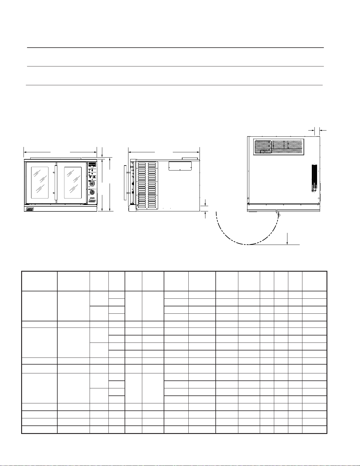
SPECIFICATIONS
15.1”
384mm
2.5”
54mm
ELECTRICAL
CONNECTION
2.5”
54mm
ELECTRICAL
CONNECTION
27.0”
687mm
0.9”
23mm
IL1520
Front View
Right Side View
Top View
W
H
D
Model Height x Width x Depth Clearance from Weight
(without optional stand) combustible surface Installed Shipping Freight Class
ECOF 27.9” x 40.1” x 39.1” Side:6”, Back: 6”, Floor: 6” 380 lbs. 420lbs 70
708mm x 1019mm x 994mm (173 kg) (191 kg)
ECOD 27.9” x 40.1” x 46.0” Side:6”, Back: 6”, Floor: 6” 460 lbs. 500lbs 70
708mm x 1019mm x 1168mm (209 kg) (227 kg)
ELECTRICAL SPECIFICATIONS
Current Number
Previous
Model
ECOD-AP ECCO-APXD-C
ECOD-AP-480V ECCO-APXD-U 480V 1 60 3 11.5 15.6 15.6 10.5 14 GA.
ECOF-AP ECCO-AP-C
ECOF-AP-380V ECCO-AP-K 380V 1 50 3 11.5 19.7 19.7 12.2 12 GA.
ECOF-AP-480V ECCO-AP-U 480V 1 60 3 11.5 15.6 15.6 10.5 14 GA.
ECOF-AP-M
ECOF-AP2/4FA ECCO-AP2/4FA 240/415V 1 50 3PH-4 WIRE 17.8 11.5 17.8 15.3 15.3 12 GA.
ECOF-AP380FA ECCO-AP-KFA 380V 1 50 3 11.5 19.7 19.7 12.2 12 GA.
ECOF-AP440VM ECCO-AP-SM 440V 1 60 3 11.7 17.5 17.5 10.8 12
ECOF-AP480VM ECCO-AP-UM 480V 1 60 3 11.5 15.6 15.6 10.5 14
ECCO-AP-CM
VOLTS ACOven
208V
240V
208V
240V
208V
240V
MOTOR
Hz.
Qty
AMPS
1
2 1/3 23 1 GA. 8.8 8.8 5.5 4 GA.
50/60 3.3
1 1/3 11.5 6 GA. 4.2 3.7 3.7 10 GA.
PHASE
1/3 11.5 6 GA. 6.0 2.7 2.7 8 GA.
AMPS 3PH /
NEUTRAL
KW TOT.
SUPPLY
WIRE 1 PH
L1 L2 L3
SUPPLY
WIRE 3 PH
2 1/3 23 2 GA. 7.8 7.8 7.3 4 GA.
1 60 3.3 11.5 6 GA. 6.0 2.7 2.7 8 GA.
2 60 3.3 23 1 GA. 8.8 8.8 5.5 4 GA.
1 60 3.3 11.5 6 GA. 4.2 3.7 3.7 10 GA.
2 60 3.3 23 2 GA. 7.8 7.8 7.3 4 GA.
1
2 1/3 23 1 GA. 8.8 8.8 5.5 4 GA.
50/60 3.3
1 1/3 11.5 6 GA. 4.2 3.7 3.7 10 GA.
2 1/3 23 2 GA. 7.8 7.8 7.3 4 GA.
1/3 11.5 6 GA. 6.0 2.7 2.7 8 GA.
4
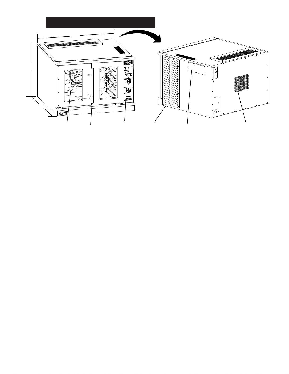
EQUIPMENT DESCRIPTION
W
Door Handle
Controls
Steam Valve
Cover
Motor Vent
Side Access
Panel
Blower
Wheel
H
D
IL1521
Exterior Construction
The oven exterior dimensions are listed in the Specication Section. The Top, Front, Back, and Sides
are constructed of heavy duty 430 stainless steel, with an attractive No. 4 nish.
The ovens simultaneous-opening heavy duty doors come standard with double pane windows.
The door handle is constructed of Stainless Steel and Phonolic Tubing.
The oven cavity is insulated with high temperature insulation for efciency and reduced heat loss.
Interior Construction
The ECOF oven cavity dimensions are 29” (72.5 cm) Wide, 20” (50.84 cm) High, 21” (53.38 cm) Deep.
The ECOD oven cavity dimensions are 29” (72.5 cm) Wide, 20” (50.84 cm) High, 27” (53.38 cm) Deep.
The interior of the oven is constructed of porcelainized stainless steel.
Operation
The ECOD-AP and ECOF-AP ovens are forced air convection ovens with a vented oven cavity.
The air is driven by a 1/3 HP fan motor.
Controls
Easy to use manual control knobs.
Solid state temperature sensing and controls.
Pulse and two-speed fan.
Technical
The ECOD-AP and ECOF-AP ovens come in voltages of 208/240V, 380V, 440V or 480V.
This must be specied when ordering.
Floor space required is 48” (122.6 cm) wide, 44” (112.5 cm) deep.
The oven weighs 430 lbs.
NOTICE The data plate is on the back side of the oven above the power cord.
The oven voltage, wattage, serial number, wire size, and clearance
specicationsareonthedataplate.Thisinformationshould
be carefully read and understood before proceeding with the
installation.
5
CAUTION
UNPACKING
Receiving the Oven
Upon receipt, check for freight damage, both visible and concealed.
Visible damage should be noted on the freight bill at the time of delivery and
signed by the carrier’s agent. Concealed loss or damage means it does not
become apparent until the merchandise has been unpacked. If concealed
loss or damage is discovered upon unpacking, make a written request for
inspection by the carrier’s agent within 15 days of delivery. All packing
material should be kept for inspection. Do not return damaged merchandise
to Star Manufacturing Company. File your claim with the carrier.
Location
Prior to un-crating, move the oven as near to its intended location as practical. The crating will help
protect the unit from the physical damage normally associated with moving it through hallways and
doorways.
Un-crating
The oven will arrive completely assembled inside a wood frame and strapped to a skid.
Cut the straps and remove the wood frame.
The oven can now be removed from the skid.
EACH UNIT WEIGHS 420 or 500 LBS. FOR SAFE HANDLING, INSTALLER
SHOULD OBTAIN HELP AS NEEDED, OR EMPLOY APPROPRIATE MATERIALS
HANDLING EQUIPMENT (SUCH AS A FORKLIFT, DOLLY, OR PALLET JACK)
TO REMOVE THE UNIT FROM THE SKID AND MOVE IT TO THE PLACE OF
INSTALLATION.
ANY STAND, COUNTER OR OTHER DEVICE ON WHICH OVEN WILL BE
LOCATED MUST BE DESIGNED TO SUPPORT THE WEIGHT OF THE OVEN.
SHIPPING STRAPS ARE UNDER TENSION AND CAN SNAP BACK WHEN CUT.
6
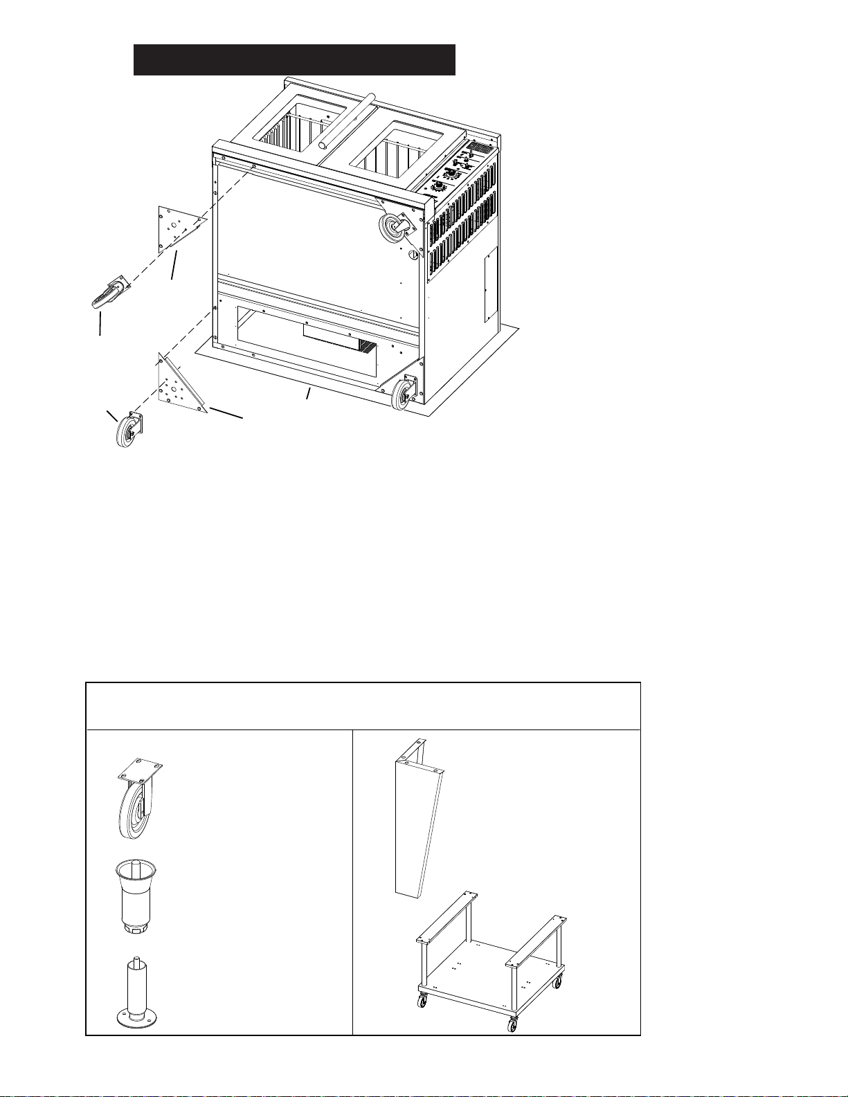
INSTALLATION
Rear
Support Assy
Front
Support Assy
Swivel
Caster
Caster
Cardboard
IL1524A
Stacked Units
Caster Sets
27” Leg Set
(marine also)
27” Equipment Cart
6” Adj. Leg Sets
6” Adj. Bolt Down Leg Sets
(marine only)
Accessory Options
Single Units
IL1525
Above: typical leg and caster installation.
Below: accessory options, legs, casters & equipment carts sold
separately. Follow installation instructions with the each specic kit.
27” Leg Installation
With unit in position, fasten the two legs to the front corner pads then to the oven’s front corners
using the four 5/16 inch bolts provided in the leg kit. See leg pad adapter illustration to dermine
differences between front & rear support assemblies.
Lift the oven onto its front legs and block the back up using one of the 27-inch legs set upside
down in the center rear of the oven body. Install the third 27-inch leg onto the oven body on the
control side rear. Gently lift the oven rear, remove the temporary support leg & install it on the last
rear corner.
Leg Installation
Legs are available separately for both the
single and double deck installations. Single
deck installations require a 27-inch leg or
equipment cart. Double deck installations
require 6-inch legs or casters. All these are
available separately.
Place some cardboard on the ground and
with assistance carefully lay the unit on its
back. In stacked
The adjustable feet may be screwed in
or out as necessary to level the oven. A
torpedo level placed on an oven rack will
assist in leveling the oven.
Double-Stack Ovens
To install the 6-inch legs, adj. feet or casters
on the lower unit, follow the Leg Pad
instructions in the following section or in the
instructions included with the leg pads.
Single Oven
To install 27” legs or cart to your unit, place
the unit laying on its back onto a piece of
cardborad. Be sure to read all instructions
& follow the instructions provided with the
kit.
7
INSTALLATION cont.
D
E
E
E
E E E E
E
E
E
A A
A
B
B
B
B
A
C
D D D
C
C
C
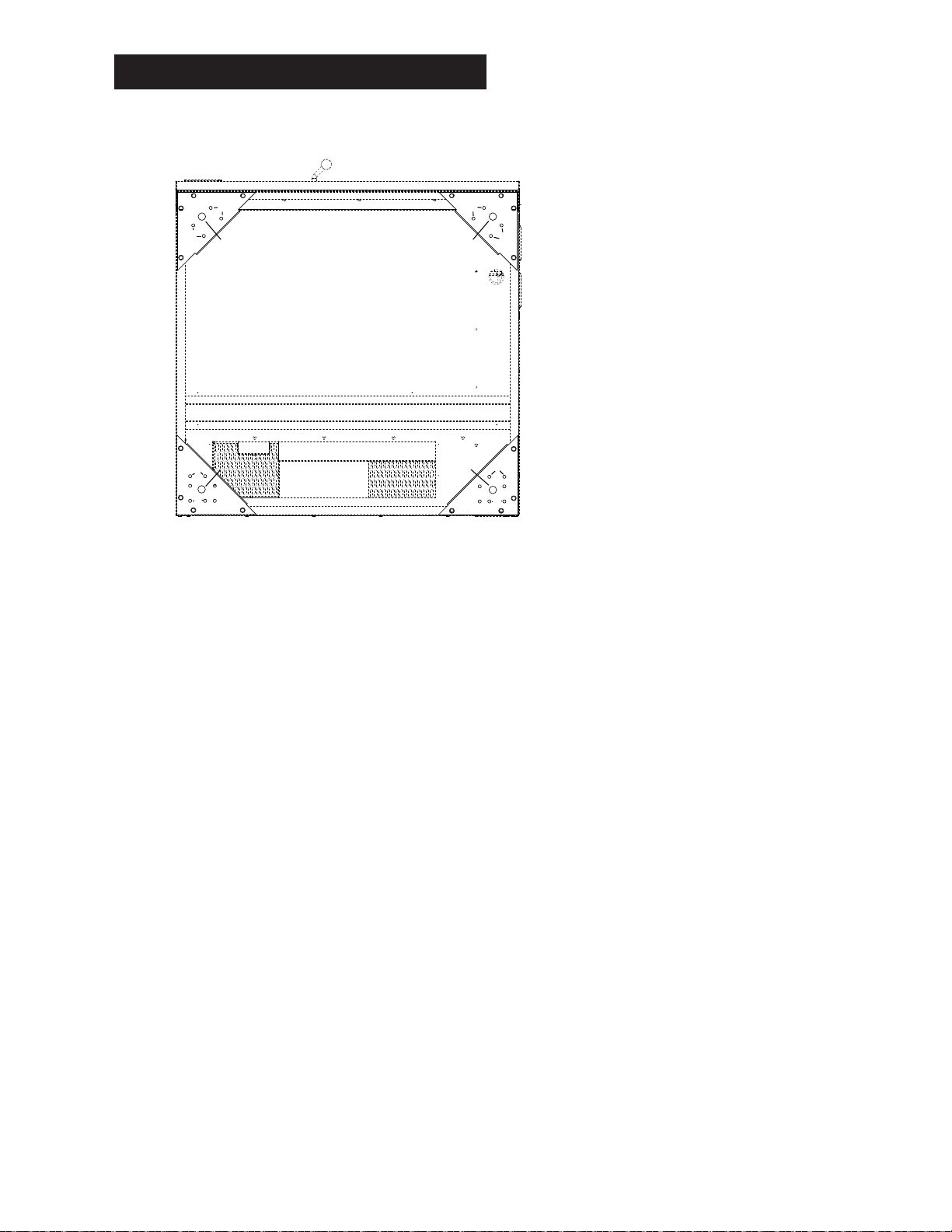
OVEN BOTTOM
OVEN FRONT
IL1523
Above: Bottom on unit showing the placement of the leg adapters
and their hole assignment.
labeled “B”. NOTE: There are two sets of “B” holes set at 90° from the each other. One set will create
a left rear adapter and the other set will create a right rear adapter.
Install four 5/16-inch bolts through the caster base and the adapter holes labeled “B” then install
5/16-inch nuts with lock washers and at washers.
Leg Pad Adapter
Identify the front and rear leg adapters (the
front adapters have two threaded inserts, the
rear has four). The leg adapters are included
with each specic accessory kit.
Leg to Adapter Installation:
Install the leg’s threaded stud through the hole
in the adapter labeled “C” with the bent ange
of the adapter facing away from the leg.
Screw the 3/4-inch nut supplied in the
adapter kit onto the leg stud and tighten.
Secure to oven using hardware provided.
Caster to Adapter Installation:
Place the swivel caster against the front leg
pad adapter with the ange of the adapter
facing away from the caster.
Install the four 5/16 inch bolts through the
caster base and the adapter holes labeled “A”
then install the 5/16 inch nuts with washer and
lock washers.
Place the rigid casters against the rear leg
adapter with the ange of the adapter facing
away from the caster.
Align the caster to the holes in the adapter
Adapter to Oven Installation:
Gently tip the oven onto its back. Place the front leg adapter into the front corers of the oven. The
holes without the threaded inserts face the front of the oven and the ange on the adapter points
toward the bottom of the oven.
The edge of the leg adapter with the threaded insert slips under the ange on the oven side, while
the edge without the inserts sits on top of the threaded angle on the oven front.
Install two 3/8-inch bolts with lock washers and at washers through the front holes “D” in the leg
adapter and into the threaded inserts on the oven.
Thread one 3/8-inch bolt with lock washer and at washer into the rear threaded hole labeled “E” on
each of the leg adapters.
The forward threaded hole on the front leg adapter does not get a bolt installed.
Place the rear leg adapters into the rear corners of the oven so that the adapter is under the ange
of the oven side and back.
NOTE: If installing a caster place the adapter on the oven so that the casters roll forward.
Install for 3/8-inch bolts with lock washers and at washers through the holes labeled “E” in the
ange of the oven and into the threaded inserts of the leg adapter.
8
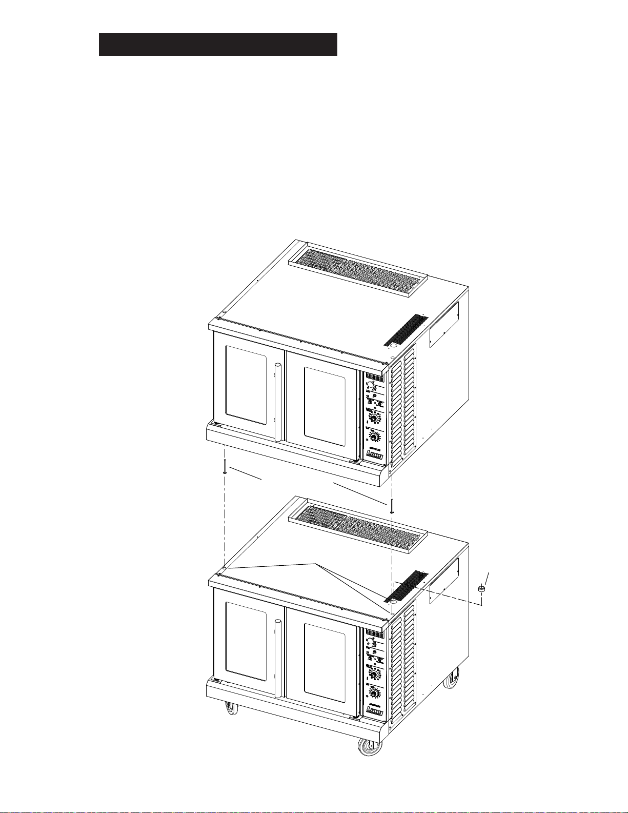
INSTALLATION cont.
Button Plugs
Bushing
Stacking Bolts
Upper Oven
Lower Oven
IL1526
Stacking the Ovens
Remove all the plug buttons from the top of the lower oven.
Remove the stacking kit from the oven compartment of one oven and install the 1 1/4-inch plastic
bushing into the top of the lower oven.
Tip the top oven backwards and install two 3/8-inch socket head bolts, found in the stacking kit,
into the two front leg holes that match the holes in the top of the lower oven. Install the socket
head bolts with the heads of the bolt pointing away from the oven.
Lift the top oven and gently set on top of the lower oven so that the heads of the socket head
bolts nest into the holes in the top of the lower oven.
NOTE: Each unit must have separate electrical connections
9
 Loading...