


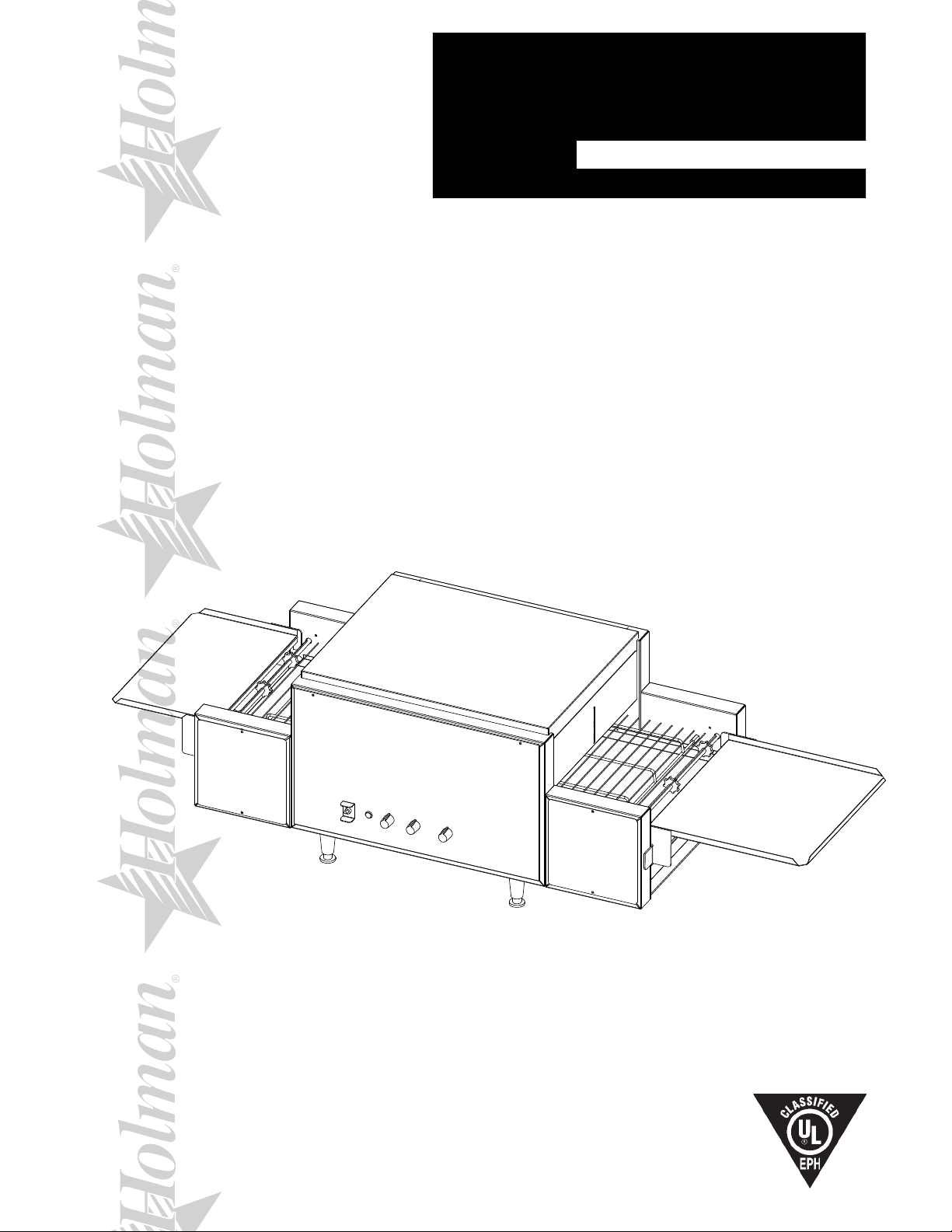
418HX
®
®
®
®
®
PROVEYOR
MULTI-PURPOSE OVEN
MODEL
314HX, 318HX Series
Installation and
Operation
Instructions
2M-HG0105 Rev. C 2/26/2010
314HX
1

SAFETY SYMBOL
Using any part other than genuine Star factory supplied parts relieves the
manufacturer of all liability.
Star reserves the right to change specications and product design without
notice. Such revisions do not entitle the buyer to corresponding changes,
improvements, additions or replacements for previously purchased
equipment.
Due to periodic changes in designs, methods, procedures, policies and
regulations, the specications contained in this sheet are subject to change
without notice. While Star Manufacturing exercises good faith efforts to provide
information that is accurate, we are not responsible for errors or omissions
in information provided or conclusions reached as a result of using the
specications. By using the information provided, the user assumes all risks in
connection with such use.
These symbols are intended to alert the user to the presence of
important operating and maintenance instructions in the manual accompanying the appliance.
RETAIN THIS MANUAL FOR FUTURE REFERENCE
NOTICE
MAINTENANCE AND REPAIRS
Contact your local authorized service agent for service or required maintenance. Please record
the model number, serial number, voltage and purchase date in the area below and have it ready when you call to ensure
a faster service.
Authorized Service Agent Listing
Model No.
Serial No.
Voltage
Purchase Date
Reference the listing provided with the unit
or
for an updated listing go to:
Website: www.star-mfg.com
E-mail Service@star-mfg.com
Telephone: (800) 807-9054 Local (314) 781-2777
Service Help Desk
Business 8:00 am to 4:30 p.m. Central Standard Time
Hours:
Telephone:
Fax: (800) 396-2677 Local (314) 781-2714
E-mail Parts@star-mfg.com
Service@star-mfg.com
Warranty@star-mfg.com
Website: www.star-mfg.com
(800) 264-7827 Local (314) 781-2777
Mailing Address: Star International Holdings Inc., Company
10 Sunnen Drive
St. Louis, MO 63143
U.S.A
2

TABLE OF CONTENTS
PAGE
Maintenance and Repairs 2
Star Contact information 2
Specications 3
General Information Data 4
Inspection & Assembly 4
Assembly and Installation 4
Heating Elements 5
Cooling System 5
Final Check 5
Electrical Connection 5
Stacking Ovens 6
Daily Operation 7
Oven Components 7
Operating Hints & Saftey 7
Cleaning 8
Maintenance Procedures 11
Troubleshooting Guide 13
Limited Equiptment Warranty 14
Wiring Diagram 15-18
Exploded View Illustration 20
Parts List 314HX 21
Parts List 318HX 22
ControlBoxConguration 23
SPECIFICATIONS
314HX
Rating/Connection: 5,400 Watts
NEMA Plug: 6-30P, 3 Phase: 6-30P
Electrical Supply: Separate service per oven - 8.7 Amp, 380/220 VAC, 3 phase, 50 Hz
Approximate Weight (314HX Oven with Legs): Installed - 86 Lbs (40 kg), Shipping - 115 Lbs (52 kg)
Dimensions: Width: 60" (152.4 cm) - Oven with Shelves
Depth: 21 1/4" (54 cm)
Height: 16 1/8" (40 cm) - Single Oven with Legs
318HX
Rating/Connection: 6,200 Watts
NEMA Plug: 6-30P, 3 Phase: 6-30P
Electrical Supply: Separate service per oven - 9.9 Amp, 380/220 VAC, 3 phase, 50 Hz
Approximate Weight (318 Oven with Legs): Installed - 96 Lbs (44 kg), Shipping - 130 Lbs (59 kg)
Dimensions: Width: 60" (152.4 cm)
Depth: 24 7/8" (63.2 cm)
Height: 16 1/8" (40 cm) - Single Oven with Legs
3
CAUTION
GENERAL INSTALLATION DATA
This equipment is designed and sold for commercial use only by personnel trained and experienced
in its operation and is not sold for consumer use in and around the home nor for use directly by the
general public in food service locations.
Before using your new equipment, read and understand all the instructions & labels associated with
the unit prior to putting it into operation. Make sure all people associated with its use understand the
units operation & safety before they use the unit.
All shipping containers should be checked for freight damage both visible and concealed. This
unit has been tested and carefully packaged to insure delivery of your unit in perfect condition. If
equipment is received in damaged condition, either apparent or concealed, a claim must be made
with the delivering carrier.
Concealed damage or loss - if damage or loss is not apparent until after equipment is unpacked, a
request for inspection of concealed damage must be made with carrier within 15 days. Be certain to
retain all contents plus external and internal packaging materials for inspection. The carrier will make
an inspection and will supply necessary claim forms.
INSPECTION & ASSEMBLY
UNCRATING AND INSPECTING
Unpack the unit and components from the shipping container. Remove all visible packing material
andthosefrominsidethecookingchamber.Ifdamageisdiscovered,leaclaimimmediatelywith
the carrier that handled the shipment. Do not operate the unit if it was damaged during shipping.
The following should be included: Proveyor Multi-Purpose Oven, Stainless Steel Load Up & Unload
Trays, 4 Stainless Steel Legs.
CAUTION
CAUTION
REMOVE ALL HEATING ELEMENT SHIPPING SUPPORTS PRIOR TO PLACING YOUR
UNIT INTO OPERATION.
ASSEMBLY AND INSTALLATION
Theunitwasshippedwithcertainassemblyrequired,plugintoastandardoutletspeciedforits
voltageandampdraw.Ifimproperelectricalsupplyisdetermined,contactaqualiedelectricianprior
to using the unit. Removal and replacement of the power cord and plug will void the warranty. For
assistance, contact your local authorized service agent for service or required maintenance.
Attach the 4 legs by screwing them into the weld nuts located on the bottom of the unit. When
complete, use two people to carefully turn the unit upright. Level unit by adjusting the feet
(approximately 1/2" adjustment). Never operate unit without proper legs in place.
Beforeusingtheunitforthersttime,wipedowntheexteriorwithadampcloth.
CAUTION
Allow enough space around the oven for adequate ventilation. Do not operate the unit without the
crumb tray properly positioned. Overheating and poor baking may occur. Read all labels on the unit
and follow their instructions.
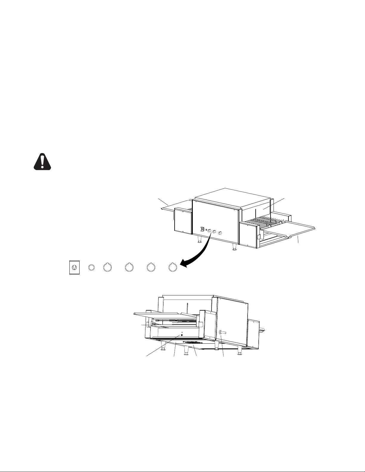
LEG INSTALLATION
4
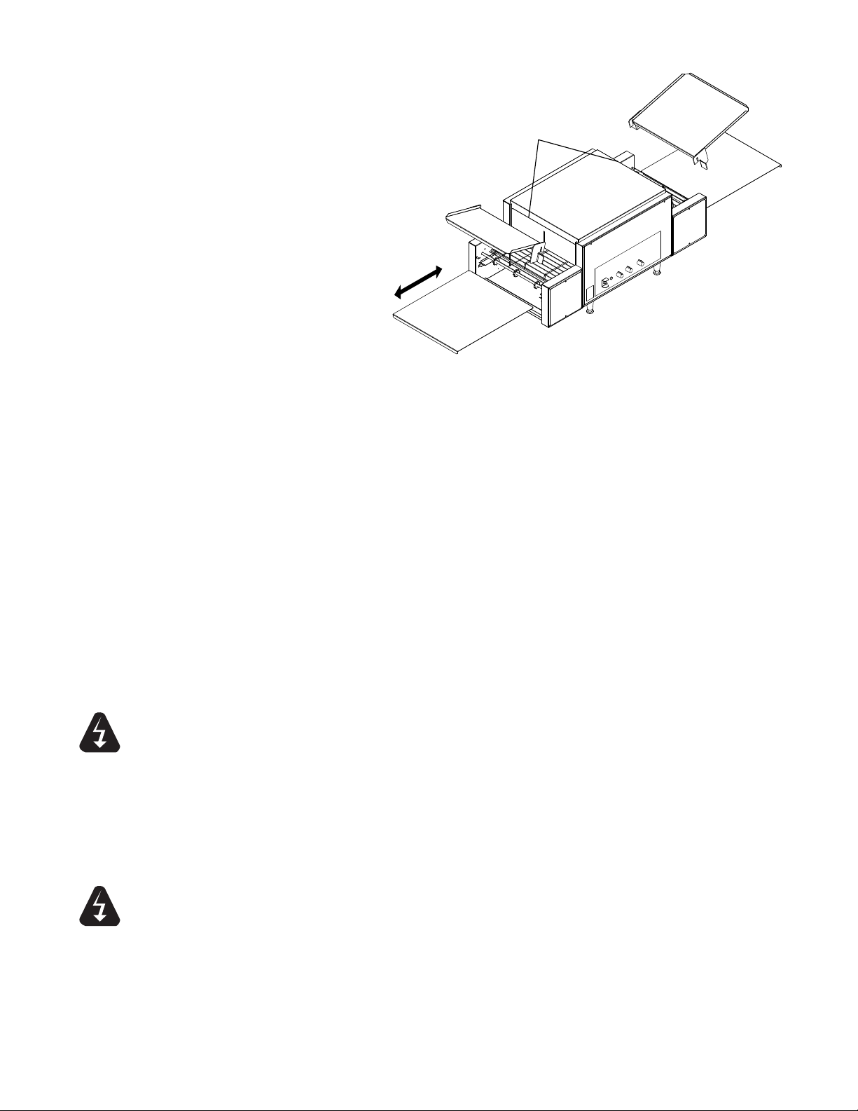
ASSEMBLY AND INSTALLATION continued
CLEAN
OPERATE
UNLOAD TRAY
LOAD TRAY
CRUMB TRAY
CRUMB TRAY
TYPICAL LEFT TO RIGHT CONFIGURATION
IL1001
ADJUSTABLE
HEAT SHUTTERS
Install unit in its operating
positionallowsufcientspacefor
operating personnel. Install the
Load, Unload and Crumb Trays
as shown, making sure the ends
are at least 6" from any vertical
combustible surfaces.
Have an electrician connect input
power to the unit(s) in accordance
with local electrical codes. A
connection terminal block is inside
the left side cavity for models not
provided with a cord and plug set.
HEATING ELEMENTS
Inspect all heating elements in
the unit for breakage. Every unit
is properly tested prior to leaving
the factory, but damage may of
occurred during shipping. If a broken tube is found, do not apply power to the unit. If everything
checks out, Turn on Main Power Switch, Turn both heat controls and conveyor belt speed control to
the maximum setting and check all heater tubes and conveyor for proper operation.
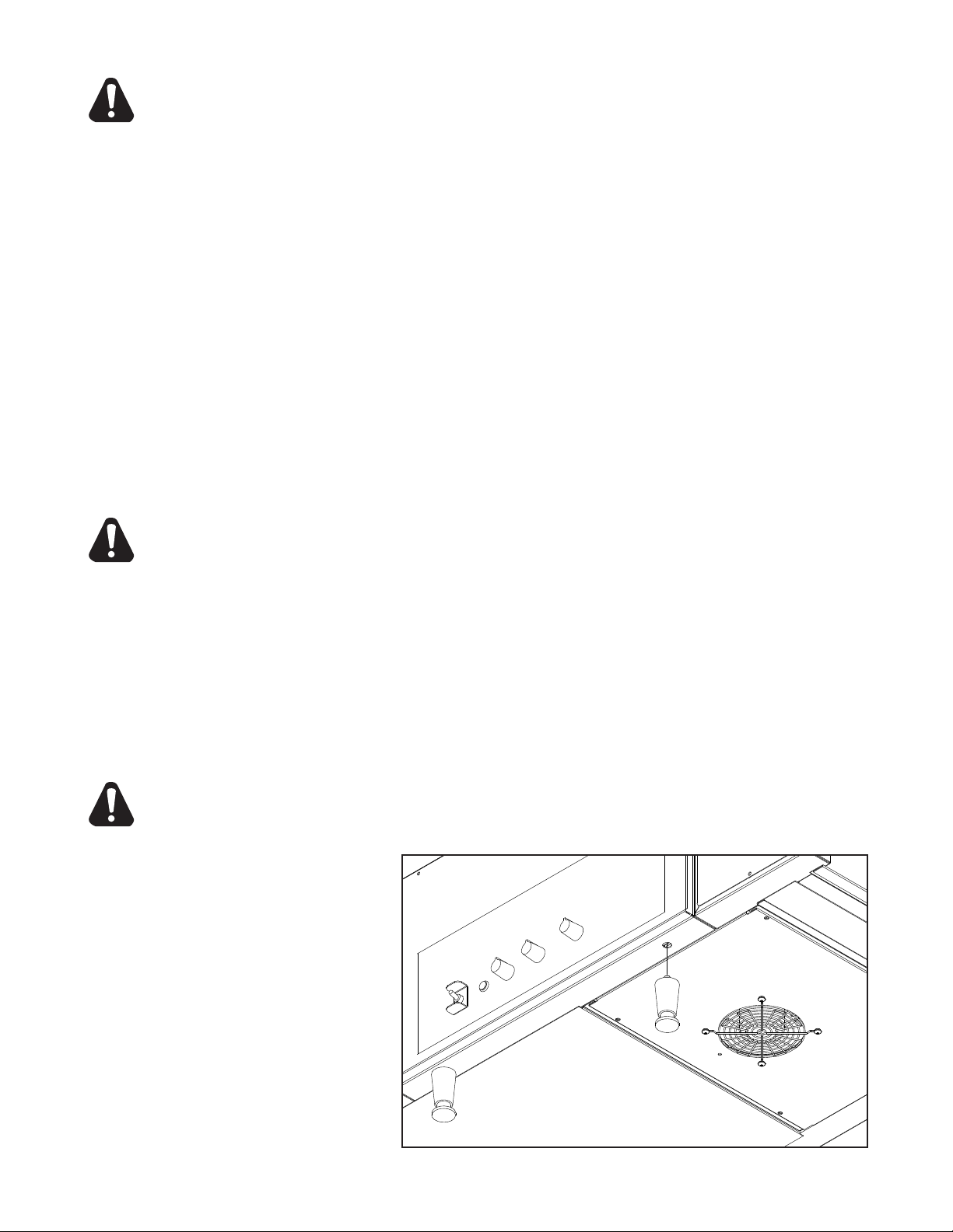
COOLING SYSTEM
After the unit is initially turned on, allow 5 to 8 minutes for the fan cooling system to come on. Once
on,checktheairintakearealocatedundertheunitandbesurethatthereisasufcientowofair
into the control box. Keep area under the unit clean from obstructions that may result in restricted air
owtothecontrolbox.Restrictingtheairowwillcausetheunittorunhotterthendesigned,causing
the Hi-Limit to turn unit off. See the Oven Components section on page 7 for control box & Hi-Limit
Reset locations.
WARNING
WARNING
FINAL CHECK
If all heaters and conveyor systems are operating properly, switch the master on/off switch to the OFF
position and allow unit to cool, the fan will continue to circulate air, cooling the unit until the internal
temperatures have been decreased.
If a problem is discovered during any of these start-up procedures, immediately switch the master
on/off switch to the OFF position and notify the Star Service Department at 1-800-807-9054.
ELECTRICAL CONNECTION
Before making any electrical connection to this unit, check that the power supply is adequate for the
voltage, amperage and requirements stated on the rating plate.
A wiring diagram is included herewith.
Disconnect the unit from the power source before installing or removing any parts.
Be absolutely sure that the ground connection for the receptacle is properly wired. Do not connect
equipment to power without proper ground connections. Improper grounding may result in personal
injury or fatality.
DO NOT CUT OR REMOVE THIS PLUG OR GROUNDING PRONG FROM THE PLUG.
CONNECT/PLUG UNIT INTO DEDICATED A.C. LINE ONLY SPECIFIED ON THE DATA
PLATE OF THE UNIT.
5
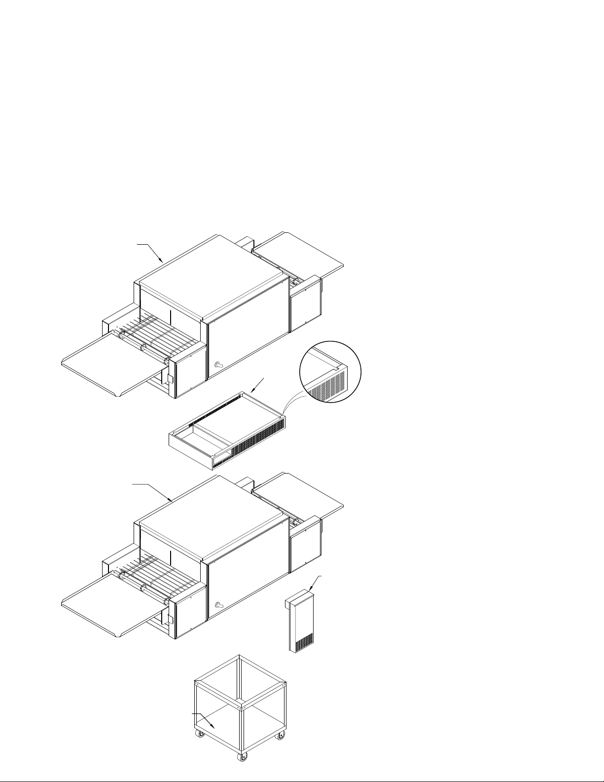
OVEN
OVEN
STACKING SPACER
EXTERNAL AIR
DUCT
EQUIPMENT
STAND
IL1020
SET-SCREW
CUT OUTS
STACKING OVENS
When stacking two Holman Proveyor Ovens a stacking spacer with an external air duct MUST be
used to prevent overheating of the control box of the top oven.
1. If a cart is to be used with units, place bottom unit on cart and align leg holes of unit with the holes
on the cart. Insert 3/8" bolts through cart and into leg holes to secure bottom unit to cart as shown
below.
2. Place stacking spacer on top of bottom oven with internal air duct facing up and towards the rear
of the oven.
3. Mount external air duct on stacking spacer as shown below. External air duct must be installed
for cooling system of top unit to function properly.
4. Screw cap screws (Qty 4) into leg hold on the top oven.
5. Place top oven on stacking spacer. Cap screws will set into cut out in top of stacking spacer to
lock unit into position.
NOTE: Air intake of top unit must
t over the internal air duct of
stacking spacer to allow airow
into the control box of the top
oven.
TOP UNIT: cap screw, screws
into leg holes, unit sits on top of
spacer.
STACKING SPACER:
(REQUIRED) Sits on top of bottom
oven.
EXTERNAL AIR DUCT: Mounts
onto spacer, pointing downward.
BOTTOM UNIT: Can be placed on
a counter or mounted on cart as
shown.
Cart:
Mounting bolts for bottom
unit screw into leg holes through
the top cart frame.
6
ADJUSTABLE HEAT SHUTTER
(QTY 2)
LOAD TRAY
UNLOAD TRAY
IL1006
ON/OFF
SWITCH
PILOT
LIGHT
UPPER
HEAT
CONTROL
LOWER
HEAT
CONTROL
CONVEYOR
SPEED
FRONT
HEAT
CONTROL
(3 Phase only)
CONTROL
BOX
HI-LIMIT
SWITCH
POWER
CORD
CRUMB
TRAY
(QTY 2)
AIR INTAKE
FAN
CAUTION
DAILY OPERATION
Baking in these units is a combination of heat and belt speed. Some foods may require more top
heat or visa versa; other foods may require low top and bottom heat and slow belt speeds. Every
product should, therefore, be tested using the separate top & bottom controls and the variable speed
control to arrive at the correct balance of heat and belt speed. When changing heat and or belt speed
setting allow approx. 5 minutes for the oven to stabilize itself at the new settings.
Check the power cord to insure that it is plugged into a proper outlet.
Always allow 10 to 15 minutes of preheat time before loading the unit with product. Failure to
allowsufcientpreheattimewillresultinunsatisfactorycookinguntiltheunitreachesoperating
temperature.
1) Turn the master on/off switch to the ON position.
2) Set both the top and bottom heat controls to 500°F (260°C).
3-Phase Control Units, set front heat controls to 500°F (260°C)
3) Turn conveyor speed control to the fastest setting.
4) Allow 10 to 15 minutes for initial warm up,
(5 to 8 minutes to reach adjusted temperature, once unit is fully warmed up)
CERTAIN SURFACES ARE EXTREMELY HOT DURING OPERATION AND CARE SHOULD
BE TAKEN WHILE USING THIS UNIT.
OVEN COMPONENTS
OPERATING HINTS AND SAFETY
Disconnect power to the unit with the switch at the end of each day of operation.
Do not leave the unit in operation without an attendant.
Do not leave the unit at high temperature when not in use or during idle periods. This will cause food
particlesandgreaselmtocarbonize.Itwilltakeonlyafewminutestoregainoperatingtemperature.
7
WARNING
IL1023
CAUTION
CLEANING
Preventive maintenance for your Holman Oven consists of the following recommended cleaning
procedures. To keep your oven in its top operating condition, these steps should be performed on a
daily, weekly or as indicated.
DISCONNECT UNIT FROM POWER SUPPLY OR TURN POWER OFF AT WALL
BREAKER.
DAILY
1. Turn main power switch to the OFF position. Disconnect unit from power source and
allow to cool.
2. Using a mild detergent, wipe exterior surfaces, clean with a damp cloth.
a. For lightly soiled build-up, clean with a damp cloth.
b. For heavily soiled build-up, use an soft damp cloth and mild detergent.
DO NOT use caustic cleaners.
3.
Remove the load & unload tray by lifting them out of position. Clean using mild detergent and
warm water.
4. Remove each crumb tray by sliding each of them out from under the conveyor belt.
Clean crumb trays by wiping with a damp cloth and mild detergent.
DO NOT use caustic cleaners. Place trays back in place prior to putting unit back into
operation.
5.
Reconnect power.
WEEKLY
1. Turn main Power switch to the OFF
position. Disconnect unit from power
source and allow to cool.
2. Perform daily cleaning procedures.
3. Using a damp cloth, wipe clean the fan
guard located on the control box cover
under the unit.
WARNING
CLEAN CONVEYOR BELT
4. Reconnect power or turn power back on.
5. Switch the ON/OFF switch to the ON
position, and turn Conveyor to its fastest
setting.
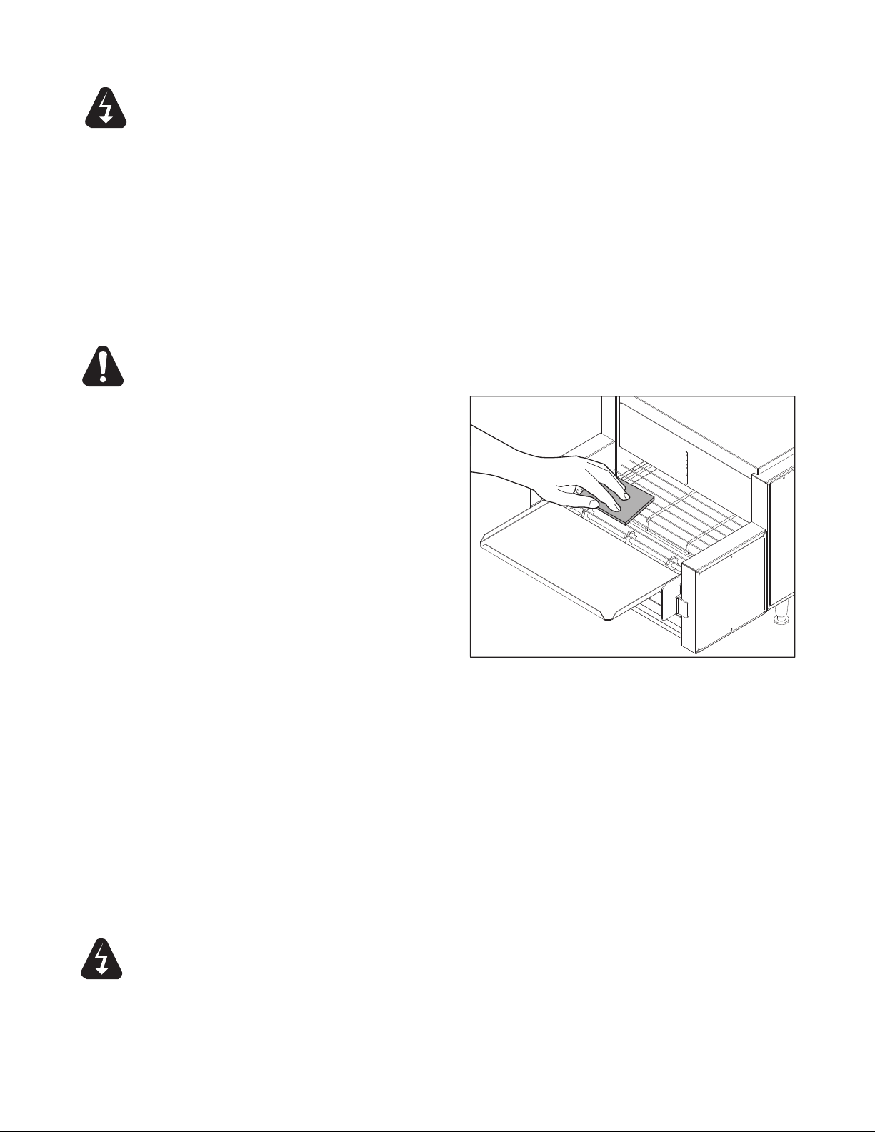
6. With the Conveyor turned on and the crumb trays in place, take a wire grill brush or dry abrasive
pad, clean the exposed surface of Conveyor Belt by passing the brush or pad, back and forth
across the surface of the Conveyor Belt as the belt moves past. Continue until the entire belt is
clean. Make sure the Crumb Tray is installed, this will minimize the amount of particles that fall
into the oven.
7. When the Conveyor Belt is clean, take a damp cloth and wipe the conveyor, removing
any loose particles on the belt surface. Turn Conveyor OFF.
8. Remove the Crumb Trays by sliding out from beneath the conveyor belt. Clean the
Crumb Trays by wiping with a damp cloth and mild detergent.
DO NOT use caustic cleaners.
DO NOT RUN CONVEYOR OVEN WITHOUT CRUMB TRAYS INSTALLED.
CLEANING CONVEYOR BELT
DO NOT IMMERSE OR LET THE UNIT STAND IN WATER.
DO NOT HOSE DOWN THE UNIT OR THE TABLE/COUNTER IF THE UNIT IS ON THE
TABLE/COUNTER.
KEEP AWAY FROM RUNNING WATER.
8
 Loading...