

Page 1
Installation,
Operation, and
Maintenance
Instructions
Electric Clamshell
Model:
CSE12-208VCD
CSE12A-1-208V
CSE12A-2-208V
CSE12A-1G thru CSE12A-6G
(Glass Surface)
Star Manufacturing International 10 Sunnen Drive St. Louis, MO.63143-3800
Part Number: 2M-W363 Ph: 800-438-5264 Fax: 314-781-2714
Rev. C www.langworld.com
June 15, 2011
Page 2
Safety
Safety
THE INFORMATION IN THIS MANUAL IS CRUCIAL AND MUST BE
RETAINED FOR FUTURE REFERENCE. READ, UNDERSTAND AND
FOLLOW THE INSTRUCTIONS AND WARNINGS CONTAINED IN THIS
MANUAL.
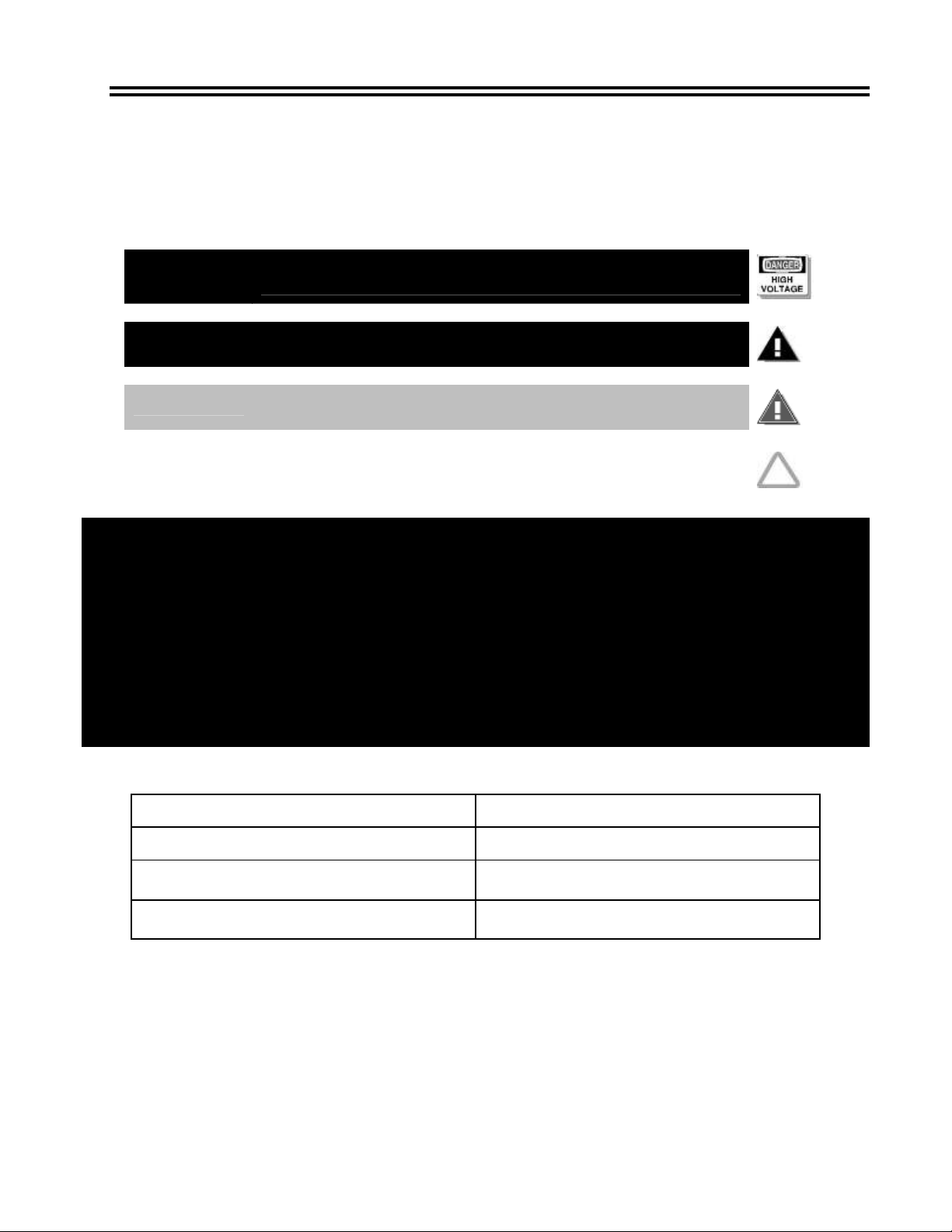
DANGER
WARNING
CAUTION
NOTICE
POTENTIALLY HAZARDOUS SITUATION, WHICH, IF NOT
AVOIDED, COULD RESULT IN DEATH.
POTENTIALLY HAZARDOUS SITUATION, WHICH, IF NOT
AVOIDED, COULD RESULT IN DEATH OR SERIOUS INJURY.
POTENTIALLY HAZARDOUS SITUATION WHICH, IF NOT
AVOIDED, MAY RESULT IN MINOR OR MODERATE INJURY.
Helpful operation and installation instructions and tips are
present.
FOR YOUR SAFETY
DO NOT STORE OR USE GASOLINE OR OTHER FLAMMABLE VAPORS OR
LIQUIDS NEAR THIS OR ANY OTHER APPLIANCE.
WARNING: IMPROPER INSTALLATION, ADJUSTMENT, ALTERATION,
SERVICE OR MAINTENANCE CAN CAUSE PROPERTY DAMAGE, INJURY
OR DEATH. READ THE INSTALLATION, OPERATING AND MAINTENANCE
INSTRUCTIONS THOROUGHLY BEFORE INSTALLING OR SERVICING THIS
EQUIPMENT.
Model #: Purchased from:
Serial #: Location:
Date purchased: Date installed:
Purchase order #: For service, call:
Page 3
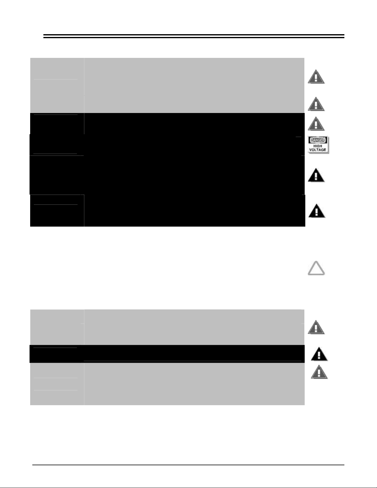
CAUTION
DANGER
DANGER
WARNING
WARNING
THE UNIT IS EXTREMELY HEAVY. FOR SAFE HANDLING, INSTALLER
SHOULD OBTAIN HELP AS NEEDED OR EMPLOY APPROPRIATE
MATERIALS-HANDLING EQUIPMENT (SUCH AS A FORKLIFT, DOLLY OR
PALLET JACK) TO REMOVE THE UNIT FROM THE SKID AND MOVE IT TO
THE PLACE OF INSTALLATION.
ANY STAND, COUNTER OR OTHER DEVICE ON WHICH UNIT WILL BE
LOCATED MUST BE DESIGNED TO SUPPORT THE WEIGHT OF THE UNIT.
WHEN CUTTING SHIPPING STRAPS, USE CAUTION, THE SHIPPING
STRAPS ARE UNDER TENSION AND CAN SNAP BACK WHEN CUT,
CAUSING SERIOUS INJURY AND OR DEATH.
GROUND THIS APPLIANCE AT THE TERMINAL PROVIDED. FAILURE TO
COMPLY MAY RESULT IN SERIOUS INJURY AND/OR DEATH.
INSTALLATION OF THE UNIT MUST BE DONE BY PERSONNEL
QUALIFIED TO WORK WITH ELECTRICITY AND PLUMBING. IMPROPER
INSTALLATION CAN CAUSE INJURY TO PERSONNEL AND/OR DAMAGE
TO EQUIPMENT. UNIT MUST BE INSTALLED IN ACCORDANCE WITH ALL
APPLICABLE CODES.
BROILER ELEMENTS CAN IGNITE GREASE FIRES ON THE GRIDDLE
SURFACE, WHICH MAY RESULT IN PROPERTY DAMAGE, SERIOUS
INJURY OR DEATH. ENSURE GRIDDLE SURFACE IS SLOPPED DOWN
FROM BACK TO FRONT BY AT LEAST ¼” BEFORE COOKING
SAFETY
NOTICE
CAUTION
WARNING
CAUTION
The data plate is located behind the Clamshell between the two pivot
arms. The Clamshell voltage, wattage, serial number, wires size and
clearance specifications are on the data plate. This information should be
carefully read and understood before proceeding with the installation.
The installation of any components such as a vent hood, grease
extractors or fire extinguisher systems must conform to their applicable
National, State and locally recognized installation standards.
During the first few hours of operation you may notice a small amount of
smoke and a faint odor from the smoke. This is normal for a new unit and
will disappear after the first few hours of use.
ALWAYS KEEP THE AREA NEAR THE APPLIANCE FREE FROM
COMBUSTIBLE MATERIALS.
KEEP FLOOR IN FRONT OF EQUIPMENT CLEAN AND DRY. IF SPILLS
OCCUR, CLEAN IMMEDIATELY TO AVOID THE DANGER OF SLIPS OR
FALLS.
KEEP WATER AND SOLUTIONS OUT OF CONTROLS. NEVER SPRAY OR
HOSE CONTROL CONSOLE, ELECTRICAL CONNECTIONS, ETC.
MOST CLEANERS ARE HARMFUL TO THE SKIN, EYES, MUCOUS
MEMBRANES AND CLOTHING. PRECAUTIONS SHOULD BE TAKEN TO
WEAR RUBBER GLOVES, GOGGLES OR FACE SHIELD AND
PROTECTIVE CLOTHING. CAREFULLY READ THE WARNING AND
FOLLOW THE DIRECTIONS ON THE LABEL OF THE CLEANER TO BE
USED.
ETL File 68964 Rev.A2007
3
Page 4

Safety
Qualified personnel must perform service on this or any other Lang
NOTICE
WARNING
CAUTION
Safety Precautions
Lang manufacturer, hereby disclaims any and all responsibility for injury, damage, loss or other
claim that may occur to person or property from improper alteration, modification, addition,
operation, maintenance or service, whether it be mechanical, electrical, or otherwise, which may
occur from such improper alteration, modification, addition, operation, maintenance or service to
this piece of equipment.
Safety Considerations
Your 12-inch Clamshell is manufactured to rigid standards. This equipment is approved by a
certifying agency to conform to safety and sanitation standards.
The presence of safety equipment control and interlocks on an appliance and attendant
components of installation cannot in and of themselves, assure absolute safety of operation.
Diligent, capable, well-trained operators and maintenance personnel, as well as proper
programs of operation and maintenance, are essential to the safe and reliable operation of this
appliance.
A. The responsibility of the manufacturer
and recommendations for the operation and maintenance of the appliance.
B. Trained qualified and factory-authorized personnel must perform all operation, maintenance
and repair of these appliances. It is the responsibility of the owner/operator to ensure
that this happens.
C. A regular periodic program of cleaning, inspection and maintenance must be established
and comprehensive maintenance records maintained. It is the sole responsibility of the
user to establish, schedule and enforce the frequency and scope of these programs in
keeping with recommended practice and with due consideration given to actual operating
conditions.
D. Operate this appliance within the limits it was designed for, which will not exceed the
working limits of any component within the appliance as a whole.
appliance only. Consult your authorized service agent directory. You
can call our toll free number 1-800-438-5264 or visit our website
www.langworld.com for the service station nearest you.
HIGH VOLTAGES ARE PRESENT INSIDE THIS APPLIANCE WHEN THE
UNIT IS PLUGGED/WIRED INTO A LIVE RECEPTACLE. BEFORE
REPLACING ANY PARTS, DISCONNECT THE UNIT FROM THE
ELECTRIC POWER SUPPLY.
USE OF ANY REPLACEMENT PARTS OTHER THAN THOSE SUPPLIED
BY Star Manufacturing International OR THEIR AUTHORIZED
DISTRIBUTORS CAN CAUSE BODILY INJURY TO THE OPERATOR AND
DAMAGE TO THE EQUIPMENT AND WILL VOID ALL WARRANTIES.
is to supply suitable, comprehensive instructions
4
Page 5

Table of Contents
Chapter Page
Safety ............................................................................................................................................................. 2
General Information...................................................................................................................................... 6
Installation..................................................................................................................................................... 7
Initial Start Up ............................................................................................................................................... 8
Cleaning......................................................................................................................................................... 9
Hood Stop Adjustment............................................................................................................................... 10
Parts List ................................................................................................................................................11-12
CSE12A-1G thru CSE12A-6G Exploded View & Parts List................................................................13-14
Wiring Diagram ........................................................................................................................................... 15
ETL File 68964 Rev.A2007
5
Page 6

General Information
General Information
Lockout Procedure
Announce lockout to other personnel.
Turn power off at main panel.
Test lockout by turning power switch on and observing if elements come on. Check heater
circuit with voltmeter.
Perform necessary repairs or tests.
Clear the unit of personnel before starting the griddle.
Turn power on at main panel.
Announce unit is “on” to other personnel.
Controls
The broiler turns on with the power switch of the griddle.
The broiler operates with full power when it is in the closed position. In the open position, the broiler will
operate with partial power and be in the “idle” mode.
Technical
The broiler, not including the griddle, is standard 208 or 240V, single phase. Specify voltage when
ordering.
Receiving the Unit
Upon receipt, check for freight damage, both visible and concealed. Note visible damage on the freight
bill at the time of delivery and have the carrier's agent sign the freight bill at that time. Concealed loss or
damage means loss or damage, which does not become apparent until the merchandise has been
unpacked. Make a written request for inspection upon unpacking and finding concealed damage within
15 days of delivery. Keep all packing material for inspection. Do not return damaged merchandise to
Star Manufacturing Company. File your claim with the carrier.
Location
Prior to un-crating, move the unit as near its intended location as practical. The crating will help protect
the unit from the physical damage normally associated with moving it through hallways and doorways.
Un-crating
The unit will arrive completely assembled inside a wood frame covered by cardboard box and strapped
to a skid. Remove the cardboard cover, cut the straps and remove the wood frame.
THE UNIT IS EXTREMELY HEAVY. FOR SAFE HANDLING, INSTALLER
SHOULD OBTAIN HELP AS NEEDED OR EMPLOY APPROPRIATE
MATERIALS-HANDLING EQUIPMENT (SUCH AS A FORKLIFT, DOLLY OR
PALLET JACK) TO REMOVE THE UNIT FROM THE SKID AND MOVE IT TO
CAUTION
Remove the unit from the skid.
THE PLACE OF INSTALLATION.
ANY STAND, COUNTER OR OTHER DEVICE ON WHICH THE UNIT WILL
BE LOCATED MUST BE DESIGNED TO SUPPORT THE WEIGHT OF THE
UNIT.
SHIPPING STRAPS ARE UNDER TENSION AND CAN SNAP BACK WHEN
CUT.
6
Page 7

DANGER
WARNING
WARNING
NOTICE
THIS APPLIANCE MUST BE GROUNDED AT THE
TERMINAL PROVIDED. FAILURE TO GROUND THE
APPLIANCE COULD RESULT IN ELECTROCUTION
AND DEATH.
INSTALLATION OF THE UNIT MUST BE DONE BY
PERSONNEL QUALIFIED TO WORK WITH
ELECTRICITY AND PLUMBING. IMPROPER
INSTALLATION CAN CAUSE INJURY TO PERSONNEL
AND/OR DAMAGE TO EQUIPMENT. UNIT MUST BE
INSTALLED IN ACCORDANCE WITH ALL
APPLICABLE CODES.
BROILER ELEMENTS CAN IGNITE GREASE FIRES ON
THE GRIDDLE SURFACE, WHICH MAY RESULT IN
PROPERTY DAMAGE, SERIOUS INJURY OR DEATH.
ENSURE GRIDDLE SURFACE IS SLOPPED DOWN
FROM BACK TO FRONT BY AT LEAST ¼” BEFORE
COOKING
The data plate is located behind the Clamshell
between the two pivot arms. The Clamshell voltages,
wattage, serial number, wire size and clearance
specifications are on the data plate. Carefully read
and understand this information before proceeding
with the installation.
Installation
Installation
The installation of any components such as a vent
NOTICE
hood, grease extractors or fire extinguisher systems
must conform to the applicable National, State and
locally recognized installation standards.
Electrical Connection
Verify griddle installation was performed as directed in the installation instructions.
Connect electrical service to the box at the back of the griddle.
Electrical specifications are located on the data plate.
Clearance
Use this griddle only in non-combustible locations.
Maintain clearances of base appliance.
ETL File 68964 Rev.A2007
7
Page 8

Initial Start Up
Initial Start Up
During the first few hours of operation, you may notice a small amount of
NOTICE
Each unit is preheated, tested and calibrated at the factory prior to shipment. However, due to
temperature and climate changes during shipment the unit can absorb moisture. Check griddle
for moisture and allow the unit to dry before placing the unit into full operation.
Prior to putting any unit into full time operation at normal cooking temperatures, it must be
thoroughly "seasoned" or dried out. Moisture absorption in the closed spaces, in the insulation
and even inside the heating elements can cause future trouble if not properly treated.
Allow the element in the unit to dry thoroughly prior to the initial use. To dry the unit, cycle the
unit on and place the hood into the down position. Allow the unit to saturate until all vapor and
condensation have been removed. For best operating results allow the unit to thoroughly dry out
for 8 to 12 hours.
Pre-heat the griddle for one hour, if the unit has been out of service for three days, especially
when exposed to high humidity and/or cool temperatures.
smoke and a faint odor from the smoke. This is normal for a new unit and
will disappear after the first few hours of use.
CAUTION
CAUTION
Once the griddle has been loaded properly, lower the hood over the product.
Elements must not touch product when clamshell is in the closed position.
ALWAYS KEEP THE AREA NEAR THE APPLIANCE FREE FROM
COMBUSTIBLE MATERIALS.
KEEP FLOOR IN FRONT OF EQUIPMENT CLEAN AND DRY. IF
SPILLS OCCUR, CLEAN IMMEDIATELY TO AVOID THE DANGER
OF SLIPS OR FALLS.
8
Page 9

Cle
KEEP WATER AND SOLUTIONS OUT OF CONTROLS. NEVER
WARNING
CAUTION
Daily Cleaning
The CSE12 broiler is a self-cleaning device. When the hood is in the down position, it
will bake off any debris that may accumulate during normal business operation.
Do not use water or cleaning solution on the elements.
Clean the exterior of the appliance with cleaner and water.
Wipe drip shield between hood and griddle to remove any grease.
Weekly Cleaning
Allow the hood to burn off any carbon build up after high use periods.
With a cold griddle, lower the hood and allow the hood to cook for 30 minutes.
Additional time may be necessary for more baked-on grease.
SPRAY OR HOSE CONTROL CONSOLE, ELECTRICAL
CONNECTIONS, ETC.
MOST CLEANERS ARE HARMFUL TO THE SKIN, EYES, MUCOUS
MEMBRANES AND CLOTHING. PRECAUTIONS SHOULD BE
TAKEN TO WEAR RUBBER GLOVES, GOGGLES OR FACE
SHIELD AND PROTECTIVE CLOTHING. CAREFULLY READ THE
WARNING AND FOLLOW THE DIRECTIONS ON THE LABEL OF
THE CLEANER TO BE USED.
Cleaning
ETL File 68964 Rev.A2007
9
Page 10

ADJUSTMENT
HOOD STOP ADJUSTMENT
Units with an Adjustable Hood Stop Installed have the capablity to adjust between a 40° to 45° degree
settings. These simple steps will assist you in accomplishing this. If you have diffi culty accomplishing this,
please call a qualifi ed service agent or Star Manufacturing Technical Service Department.
1. Remove the front bolts from the hood stop, and loosen the back bolts up, do not completely
remove the back bolts.
2. Adjust the hood stop to the desired position, the top hole is to stop the hood at 40° degrees the
bottom hole is to stop the hood at 45° degrees.
3. Re-install the front bolts and tighten up the back bolts.
Hood Stop
Front Bolt
Rear Bolt
(Fig. 1)
Page 11

Parts List
Parts List
ETL File 68964 Rev.A2007
11
Page 12

Parts List December 5, 2007, Rev. C
Model: CSE12-208VCD, CSE12A-1-208V, CSE12A-2-208V
Item Part Description Qty Application
1 2N-11160-32-2 STLHTR208VXLH1600W42.5WSI
1A 2N-11160-32-4 STLHTR240VXLH1600W42.5WSI
2 2E-30500-02 TRM STRP 4 POLE 30A 600V
3 2E-30501-03 TERM STRP 4 POLE W/PUSH
4
5 2J-40302-02 CANCTR/RECEPTACLE GGB
6 2P-51002-15 HOOD SPRING XLH12 NEW
7 K9-60102-13582 BRIDGE TO HOOD WIRE
8 K9-60102-13588 ROD ASY HOOD SPRNG XLH12
9
10 2K-70801-04 SNAP BUSH 3/4 SB750-10
11 K9-EZG-418-1
12 K9-EZG-429 SPOT CONNECTOR MOUNT
13 K9-EZG-430 BOX HEAT SHIELD COMBO
14 K9-EZG-433 BOX HEAT SHIELD #2 COMBO
15 K9-EZG-436-1 BOX HEAT SHIELD SPACER
16 K9-XLH-709-1 HANDLE ASSY. CSE12
17 K9-XLH-740-1 Hood switch svc kit
17 2E-30307-04 SWT MERCURY TILT HI-TEMP
18 K9-XLH-636-21 BRIDGE COVER 2' CSE12 NO
19 K9-XLH-659 RIGHT STANCHION COVER
19 K9-XLH-659-1 RIGHT STANCHION CVR
20 K9-XLH-660-1 LEFT STANCHION CVR
21 K9-XLH-735-221 CON. BOX/FLUE 2'GAS-12 NO
NI K9-XLH-704-01 ELEMENT ASSY 208
NI K9-XLH-704-02 ELEMENT ASSY 240
NI K9-XLH-781 HOOD STOP BRACKET
NI 2A-XLH-782 HOOD STOP
2E-30705-01 CONTC 2-SPD MTR-COIL 240VA
2E-30705-02 CONTC 2-SPD MTR 25A 24VAC
K9-60102XLH609
FRONT HOOD WRAP
OUTER BOX SPOTWELD
CSE12
CSE12-208VCD, A-1-208, A-2-208,
2
A-3-208, A-4-208, A-5-208, A-6-208
CSE12A-1-240, A-2-240, A-3-240,
2
A-4-240, A-5-240, A-6-240
1 ALL
1 ALL
1 ALL ELECTRIC GRIDDLES
1 ALL GAS GRIDDLES
1 ALL
1 ALL
1 ALL
1 ALL
1 ALL
1 ALL
1 ALL
1 ALL
1 ALL
1 ALL
1 ALL
1 ALL
1 ALL
2 ALL
1 ALL
1 ALL
1 ALL
1 ALL
1 ALL
CSE12-208VCD, A-1-208, A-2-208,
1
A-3-208, A-4-208, A-5-208, A-6-208
CSE12A-1-240, A-2-240, A-3-240,
A-4-240, A-5-240, A-6-240
1
1 CSE12-208VCD
2 CSE12-208VCD
12
Page 13

SK2522, Rev. -, 6/15/2011
Model: CSE12A-1G thru CSE12A-6G
CLAMSHELL HOOD GLASS
Purchase these
items together
1
2
3
1
25
26
27
22
23
24
4
5
7
8
9
1
13
15
1
19
20
21
16
17
14
12
11
10
6
18
Page 14

PARTS LIST June 15, 2011
Model: CSE12A-1G thru 6G, Clamshell Hood Glass
Fig No. Part Number Description Qty Application
1 2C-20111-09 SCRW HXHD CAP 10-32X1/2 24
2 K9-XLH-706-W1 REAR COVER ASSEMBLY-XLH12 1
3 K9-XLH-734 BRIDGE TO HOOD WIRE 1
4 K9-XLH-788 BASE - ELEMENT BRACKET 2
5 K9-XLH-789 BRACKET - ELEMENT 4
2N-11160-32-2 STLHTR208VXLH1600W42.5WSI
6
2N-11160-32-4 STLHTR240VXLH1600W42.5WSI 240V
7 2Q-71300-20 GLASS - HIGH TEMP CERAMIC 1
8 1P-72602-38 TAPE-FIBERGLASS 1”x1/16TK 5.21 FT
9 K9-XLH-268 FRAME - GLASS CLAMSHELL 1
10 2C-Z6925 SCREW #8X1/2 HEXW B SS 6
11 K9-XLH-705-01 ELEMENT HOLDER ASSY 1
12 K9-XLH-628-01 ELEMENT CLAMP 1
13 2C-20301-11 NUT HEX 8-32 PLTD 2
14 2C-20202-12 WSHR LOCK #8 INT STAR 2
15 K9-XLH-742-1 MERCURY SWITCH BRACKET 1
16 K9-XLH-741-1 MERCURY SWITCH BASE 1
17 2C-20101-28 SCRW THD MS 8-32X3/8 PLTD 2
18 2I-70803-04 CERMC INSLTR 9/32ID11/16 1
19 2E-30307-04 SWITCH MERCURY TILT 2
20 K9-60102-13588 ROD ASSY HOOD SPRNG 1
21 2P-51002-15 HOOD SPRING XLH12 NEW 1
22 K9-XLH-611 HANDLE BRACE TOP 1
23 K9-XLH-612 HANDLE BRACE BOTTOM 1
24 2C-20104-61 SCRW 1/4-28X3/4 FLT HD SO 2
25 K9-XLH-709-1 HANDLE ASSY. CSE12 1
26 K9-XLH-707 FOREWARD HOODWRAP ASSY 1
27 2M-60301-W2 LANG CLAMSHELL LOGO 1
2
208V
1
IMPORTANT: WHEN ORDERING, SPECIFY VOLTAGE OR TYPE GAS DESIRED PAGE
1
INCLUDE MODEL AND SERIAL NUMBER OF
Some items are included for illustrative purposes only and in certain instances may not be available.
Page 15

Wiring Diagram
Wiring Diagram
ETL File 68964 Rev.A2007
13
Page 16

STAR INTERNATIONAL HOLDINGS INC. COMPANY
Star - Holman - Lang - Wells - Bloomeld - Toastmaster
10 Sunnen Drive, St. Louis, MO 63143 U.S.A.
(314) 781-2777
www.star-mfg.com
 Loading...