

Page 1

OPERATOR'S MANUAL
HOLMAN CONVEYOR TOASTERS
MODEL B910
FOR SERVICE INFORMATION
U.S. AND CANADA CALL: 1-800-225-3958
24 HOURS/DAY 7 DAYS/WEEK
TABLE OF CONTENTS
UNCRATING AND INSPECTION PAGE 1
ASSEMBLY AND INSTALLATION PAGE 1, 2
POWER SAVER SWITCH PAGE 2
COOKING PROCEDURES PAGE 3, 4
CLEANING PROCEDURES PAGE 4
TROUBLESHOOTING GUIDE PAGE 5, 6
MAINTENANCE PROCEDURES PAGE 7, 8, 9
PARTS LIST PAGE 10
DRAWINGS
HEAT REFLECTOR/CRUMB TRAY PAGE 1
LOAD AND UNLOAD TRAYS PAGE 1
ADJ. HEAT SHIELD, FRONT VIEW PAGE 3
COMPONENT ARRANGEMENT PAGE 6 & 8
HEATER TUBE INSTALLATION PAGE 7
DRIVE SYSTEM PAGE 9
WIRING DIAGRAM PAGE 11
FILE:F\MICHAEL\MANUALS\B910VA
HG0153
REV. 1-31-96
MJC
Page 2
OPERATOR'S MANUAL
HOLMAN CONVEYOR TOASTERS
UNCRATING AND INSPECTION
MODEL B910
Unpack unit and components from container. Remove all visible packing
material, inspect unit for damage. If damage is discovered, file a claim
immediately with the carrier that handled the shipment.
ASSEMBLY AND INSTALLATION
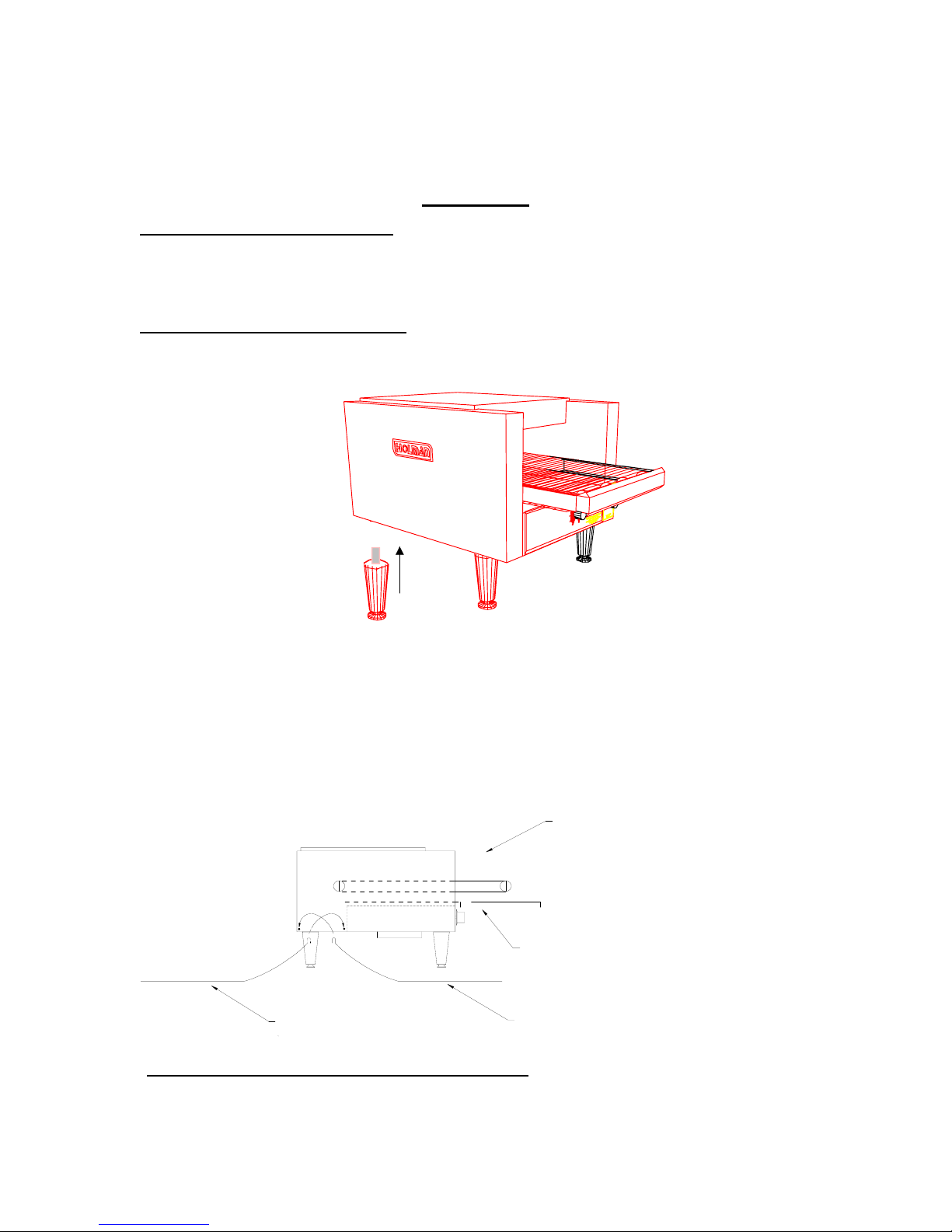
A. Attach legs by screwing into weld nuts, as shown below.
Page 1
LEG SCREWS INTO
WELD NUT AT BOTTOM
OF UNIT
B910LEG.WMF
B. Anti Skid pads are available at no charge and may be adhered to the foot
section of each leg to prevent sliding. Call 1-800-225-3958 for details.
WARNING: Use of these pads are not approved by the National Sanitation
Foundation.
C. Place unload tray as shown below.
(REAR DISCHARGE)
LOAD UP AREA
CAUTION: DO NOT OPERATE UNIT WITHOUT
CRUMB TRAY PROPERLY POSITIONED
AS THIS WILL CAUSE OVERHEATING IN THE
CONTROL BOX.
HEAT REFLECTOR / CRUMB TRAY
TOAST CHUTETOAST CHUTE
Assembly and installation continued on page 2
REV. 1-30-96 MJC
Page 3

Page 2
OPERATOR'S MANUAL
HOLMAN CONVEYOR TOASTERS
ASSEMBLY AND INSTALLATION CONT.
WARNING
: MAKE SURE ALL INPUT POWER IS OFF BEFORE
INSTALLING/REMOVING ANY PARTS.
WARNING
WARNING
: BEFORE INSTALLING UNIT(S), CHECK WITH LOCAL POWER
COMPANY TO DETERMINE ACTUAL VOLTAGE AT JOB SITE.
NEVER PLUG A 208 VOLT UNIT INTO 240 VOLTS OR A 240
VOLT UNIT INTO 208 VOLTS.
: BE ABSOLUTELY SURE THE GROUND CONNECTION FOR THE
MODEL B910
RECEPTACLE IS PROPERLY WIRED. NEVER CONNECT UNIT TO
POWER SAVER SWITCH
POWER WITHOUT PROPER GROUND CONNECTIONS. IMPROPER
GROUND MAY RESULT IN SEVERE INJURY OR FATALITY.
Your Holman toaster is equipped with a Power Saver Switch, details are as
follows;
WHEN POWER SAVER IS IN FULL
POWER POSITION, ALL THE HEATER
TUBES ARE ENERGIZED FOR TOASTING.
FULL POWER
WHEN POWER SAVER IS IN STAND-BY
POSITION, ALL OF THE ELEMENTS
OFFOFF
1/4 POWER
STAND BY
ROTARY POWER SAVER
ARE ENERGIZED AT 1/4 POWER
USING YOUR POWER SAVER SWITCH
Power Saver
Switch Positions
FULL POWER- When in this position your unit is at Full Power and ready to use.
Conveyor Belt Speed Control to your desired settings.
OFF-ROTARY: Two off positions are provided so that a single rotation to either
direction will result in the unit being turned OFF.
STANDBY- The standby position reduces the power to the unit to 1/4, and
therefore saves 75% of the energy consumption. In this position your
unit will stay warm and reduce the reheat time when switched to Full
Power to 20 to 30 seconds.
REV. 8/4/97 MJC
Page 4

PAGE 3
R
OPERATOR'S MANUAL
HOLMAN CONVEYOR TOASTERS
COOKING PROCEDURES
MODEL B910
A. BAGEL TOASTING
1. On model B910 lower the Front Heat Shield all the way down, leave just
enough clearance for bagel slices to pass under the shield into the
cooking cavity (See illustration below).
ADJUSTABLE HEAT SHUTTE
2. Turn power saver to the full power position. Three top elements and one
lower element are now at full power. Turn Variable Speed Control
to 50.
3. Allow warm up time of 5 to 10 minutes.
4. Test with a bagel half.
a. If bagel is too light, turn Variable Speed Control counterclockwise to a
slower speed.
b. If bagel is too dark, turn Variable Speed Control clockwise to a faster
speed.
B. BUN TOASTING
1. Turn power saver to the full power position. Turn Variable
Speed Control to 50.
2. Lower the front heat shield as far as possible, leave just enough
clearance for the bun half to pass under and into the cooking cavity.
Refer to bagel toasting step 1 for adjustment instructions.
3. Test with a half of a bun.
a. If bun half is too light, turn Variable Speed Control counterclockwise
to a slower speed.
b. If bun half is too dark, turn conveyor speed control clockwise to a
faster speed.
Cooking procedures continued on page 4
REV. 11/14/97 MJC
Page 5

PAGE 4
0
OPERATOR'S MANUAL
HOLMAN CONVEYOR TOASTERS
MODEL B910
COOKING PROCEDURES CONT.
The model B910 has three tubes on the top and one on the bottom. Therefore
when placing the bun or bagel halves on the conveyor you should place them
cut side up.
CLEANING PROCEDURES
1. Turn Rotary Power Saver to the FULL POWER position.
2. For lightly soiled conveyor belts, turn Variable Speed Control to fastest
setting (100) and wipe with a damp cloth.
3. For heavily soiled conveyors, turn Variable Speed Control to fastest setting
(100) and wipe with a light abrasive pad.
4. Turn Rotary Power Saver to the OFF position.
5. After the unit cools, remove interior Crumb Tray (as shown below) and
clean. Slide Crumb Tray back into position. DO NOT OPERATE UNIT
WITHOUT CRUMB TRAY IN PLACE AS THIS CAUSES OVERHEATING IN
THE CONTROL BOX AND MAY ACTIVATE THE HEAT LIMIT SWITCH.
6. Wipe exterior surface of unit.
LUBRICATION OF DRIVE CHAIN WITH A GRAPHITE BASED LUBRICANT IS REQUIRED AS
PERIODIC MAINTENANCE. CALL HOLMAN FACTORY SERVICE DEPARTMENT FOR
DETAILS.
LOAD UP AREA
IDLER SHAFT
HEAT REFLECTOR / CRUMB TRAY
REV.12/23/96 MJC
(TOP VIEW)
SHOWN WITHOUT TOP COVER
DRIVE SHAFT
CONVEYOR LINK, MODEL T71
CONVEYOR BELT
Page 6

PAGE 5
OPERATOR'S MANUAL
HOLMAN CONVEYOR TOASTERS
TROUBLESHOOTING GUIDE
A. UNIT WILL NOT HEAT, CONVEYOR WILL NOT TURN.
1. Be sure the main circuit breaker is switched to the ON position.
MODEL B910
2. Check to see if the toaster is plugged in and all controls are turned to the
ON
B. UNIT WILL NOT HEAT, CONVEYOR TURNS PROPERLY.
position.
1. Check to see if Rotary Power Saver has been turned to the FULL
POWER position.
2. Push Heat Limit Switch on rear of Control Box as shown below.
If this reactivates the Heater Tubes, see HEAT LIMIT SWITCH in
section C.
C. HEAT LIMIT SWITCH
Your Holman conveyor toaster is equipped with an automatically activated
Heat Limit Switch which interrupts the heater tube connections if the ambient
temperature in the Control Box exceeds 190F (88C). This Heat Limit Switch
can be reset manually by pushing the red button on the rear of the Control
Box as shown below.
LOAD UP AREA
RESET
HEAT REFLECTOR / CRUMB TRAY
THE HEAT LIMIT SWITCH IS ACTIVATED WHEN THERE IS NOT
SUFFICIENT AIR FLOW GENERATED BY THE COOLING FAN. WHEN
HEAT LIMIT SWITCH HAS BEEN ACTIVATED:
1. DISCONNECT UNIT FROM POWER SOURCE.
2. Check to see if air intake area in the bottom center of the Control Box
cover is free of dust, grease or other obstructions.
Troubleshooting guide continued on page 6
REV. 8/4/97 MJC
Page 7

PAGE 6
OPERATOR'S MANUAL
HOLMAN CONVEYOR TOASTERS
MODEL B910
TROUBLESHOOTING GUIDE CONT.
3. Check if Crumb Tray is in place. NEVER OPERATE UNIT WITHOUT
CRUMB TRAY IN PLACE AS THIS CAUSES OVERHEATING IN THE
CONTROL BOX.
4. If no obstructions to the air flow can be found and if the Crumb Tray is in
place, call Holman Factory Service Department at 1-800-225-3958 for
assistance.
D. CONVEYOR WILL NOT TURN, UNIT HEATS PROPERLY.
1. DISCONNECT UNIT FROM POWER SOURCE.
2. Remove right hand side panel (from operator's position). Loosen screws
holding Drive Motor in place and slide motor toward the rear of unit.
Remove Drive Chain and manually move conveyor belt to check for
mechanical binding. If conveyor moves freely, call Holman Factory
Service Department at 1-800-225-3958 as Drive Motor and/or Variable
Speed Control may need replacement.
DRIVE CHAIN
DRIVE
SPROCKET
REAR BEARING
DRIVEN
SPROCKET
CUT AWAY VIEW OF CONTROL BOX
1- ROTOR
2- FIELD/STACK
3- GEAR BOX
4- MOUNTING
SCREW
5- DRIVE SPROCKET
6- MOTOR SHAFT
7- SET SCREW
4
1
2
6
3
4
5
7
E. DRIVE MOTOR RUNS AT ONE SPEED REGARDLESS OF SPEED
CONTROL SETTING.
1. Call Holman Factory Service Department at 1-800-225-3958 as Variable
Speed Control should be replaced.
REV. 12/23/96 MJC
DRVMTR.WMF
Page 8

PAGE 7
E
OPERATOR'S MANUAL
HOLMAN CONVEYOR TOASTERS
MAINTENANCE PROCEDURES
A. REPLACING HEATER TUBES (as below)
1. DISCONNECT UNIT FROM POWER SOURCE.
2. Remove right and left side panels.
MODEL B910
3. Remove heater tube wire from terminal block connection, keeping
top and bottom wires separate.
4. Remove heater tube retainers by removing retaining screws with washer.
5. Gently,
6. Gently,
pull defective Heater Tube out of unit.
put new Heater Tube into unit.
7. Replace Heater Tube Retainers, reconnect heater tube wires to terminal
block and install side panels.
HEATER TUBE RETAINER
HEATER TUBE
TERMINAL STRIP
(4 P.O.S.)
B910RET.WMF
SIDE PANEL
HEATER TUBE RETAIN
HEATER TUBE
Maintenance procedures continued on page 8
REV. 1-30-96 MJC
Page 9

PAGE 8
OPERATOR'S MANUAL
HOLMAN CONVEYOR TOASTERS
MODEL B910
MAINTENANCE PROCEDURES (CONT.)
B. REPLACING FAN MOTOR
1. DISCONNECT UNIT FROM POWER SOURCE.
2. Remove Control Box Cover with Fan Motor attached.
3. Unplug power supply cord from Fan Motor.
4. Remove(4)screws which hold Fan Motor and grill to cover.
5. Put replacement motor and grill in place and secure to the Control Box
Cover with screws.
6. Reconnect power supply cord to Fan Motor.
7. Replace Control Box Cover.
CONTROL BOX COVER
AIR INTAKE
FAN MOTOR
SECURED BY 4 SCREWS
AIR INTAKE SCOOP
Maintenance procedures continued on page 9
REV. 8/4/97 MJC
Page 10

PAGE 9
OPERATOR'S MANUAL
HOLMAN CONVEYOR TOASTERS
MODEL B910
MAINTENANCE PROCEDURES (CONT.)
C. REPLACING BELT DRIVE MOTOR
1. DISCONNECT UNIT FROM POWER SOURCE.
2. Remove right side panels and Control Box Cover.
3. Remove sprocket from motor shaft.
4. Remove the wire from terminal block connecting the Drive Motor to
internal wiring. On units rated 208 volts the white wire is used and on 240 volt
units the blue wire is used. Note which color leads are being used for these
connections and which lead is capped with white tape. The new motor should
use the same arrangement.
5. Remove screws holding motor in place.
6. Put new motor in place and attach loosely with mounting screws.
7. Replace sprocket on motor shaft.
8. Slide motor until the Drive Chain has about 1/8" slack when lightly pushed
at the center of its top open run.
9. Tighten screws to secure motor.
10. Rewire leads same as removed in step 4.
11. Replace side panel and Control Box Cover.
IF ASSISTANCE IS REQUIRED FOR THIS OR ANY OTHER PROCEDURE IN THIS
MANUAL CALL HOLMAN FACTORY SERVICE DEPARTMENT AT 1-800-225-3958.
24 HOURS/DAY 7 DAYS/WEEK
DRIVE CHAIN
DRIVE
SPROCKET
REAR BEARING
DRIVEN
SPROCKET
CUT AWAY VIEW OF CONTROL BOX
1- ROTOR
2- FIELD/STACK
3- GEAR BOX
4- MOUNTING
SCREW
5- DRIVE SPROCKET
6- MOTOR SHAFT
7- SET SCREW
1
4
6
2
3
4
5
7
DRVMTR.WMF
REV. 8/4/97 MJC
Page 11

OPERATOR'S MANUAL
HOLMAN CONVEYOR TOASTERS
MODEL B910
WIRING DIAGRAM FOR MODEL B910 208/240 VOLTS 60 Hz
POWER SAVER
DRIVE
MOTOR
SPEED CONTROL
WHITE- 208 VAC
BLUE- 220/240 VAC
BLACKCOMMON
PAGE 11
RESET SWITCH
PLUG CONFIGURATION
6-20P 20 AMP
REV 2/22/99 MJC
POWER
SUPPLY
GROUND
PILOT
LIGHT
FAN MOTOR
FAN SWITCH
Page 12

PAGE 10
OPERATOR'S MANUAL
HOLMAN CONVEYOR TOASTERS
MODEL B910
PARTS LIST
PART#
QTY PAGE# DESCRIPTION
197841 4 7 Heater Tube, 208V
197842 4 7 Heater Tube, 240V
200566 1 5 Heat Limit Switch, 190F
160005 1 4 Conveyor Belt
400833 4 7 Heater Tube Retainers
150000 1 6 Drive Chain
100900 1 4 Drive Shaft
100904 1 4 Idler Shaft
112261 4 6 Bearing 5/16 I.D.
200509 1 9 Drive Motor 208-240V
200703 1 6 Knob, Control
200560 1 8 Fan Motor, 208/240V
118042 1 6 Speed Control 208-240
200562 1 Not Shown Fan Grill
100528 1 4 Crumb Tray
200551 1 2 Power Saver Switch, Rotary
200387 1 13 Cord/Plug Set, (Fan Motor)
140038 1 13 Cord/Plug Set
200537 1 Not Shown Fan Switch
REV. 10-9-96 MJC
 Loading...