

Page 1
®
®
®
®
®
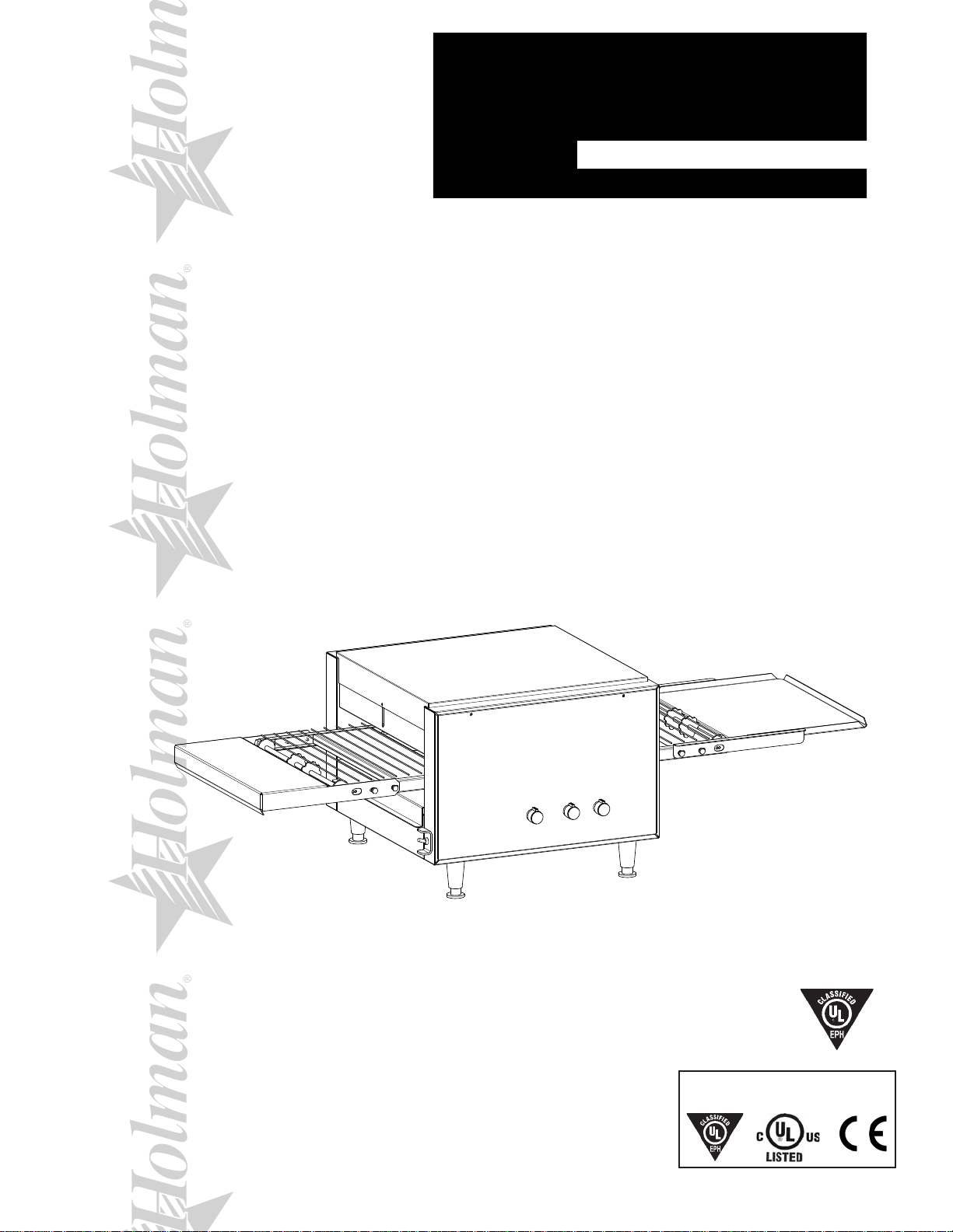
MINIVEYOR
MULTI-PURPOSE OVEN
MODEL
210HX, 214HX Series
Installation and
Operation
Instructions
2M-HG0104 Rev. J 1/18/2012
214HX
1
ALL MODELS
210HX-V67 & V68
214HXA-V68
Page 2

2
These symbols are intended to alert the user to the presence of
important operating and maintenance instructions in the manual
accompanying the appliance.
RETAIN THIS MANUAL FOR FUTURE REFERENCE
NOTICE
Using any part other than genuine Star factory supplied parts relieves the
manufacturer of all liability.
Star reserves the right to change specications and product design without
notice. Such revisions do not entitle the buyer to corresponding changes,
improvements, additions or replacements for previously purchased
equipment.
Due to periodic changes in designs, methods, procedures, policies and
regulations, the specications contained in this sheet are subject to change
without notice. While Star International Holdings Inc., Company exercises
good faith efforts to provide information that is accurate, we are not
responsible for errors or omissions in information provided or conclusions
reached as a result of using the specications. By using the information
provided, the user assumes all risks in connection with such use.
MAINTENANCE AND REPAIRS
Contact your local authorized service agent for service or required maintenance.
Please record the model number, serial number, voltage and purchase date in the area below and have it ready when
you call to ensure a faster service.
SAFETY SYMBOL
Model No.
Serial No.
Voltage
Purchase Date
Business 8:00 am to 4:30 p.m. Central Standard Time
Hours:
Telephone: (314) 678-6303
Fax: (314) 781-2714
E-mail Parts@star-mfg.com
Service@star-mfg.com
Warranty@star-mfg.com
Website: www.star-mfg.com
Service Help Desk
Authorized Service Agent Listing
Reference the listing provided with the unit
or
for an updated listing go to:
Website: www.star-mfg.com
E-mail Service@star-mfg.com
Mailing Address: Star International Holdings Inc., Company
10 Sunnen Drive
St. Louis, MO 63143
U.S.A
2
Page 3

SPECIFICATIONS
210HX-120V - 60Hz
Rating/Connection: 1,700 Watts
NEMA Plug: 5-15P, CUL 5-20P
Electrical Supply: Separate service per oven - 14.2 Amp, 120 VAC, 60 Hz
Approximate Weight (210HX Oven with Legs): Installed - 61.5 Lbs (28 kg), Shipping - 39.5 Lbs (18 kg)
Dimensions: Width: 46 11/16" (118.6 cm) - Oven with Shelves
Depth: 15 7/16" (39.2 cm)
Height: 14" (35.5 cm) - Single Oven with Legs
210HX-208V - 60Hz
Rating/Connection: 2,800 Watts
NEMA Plug: 6-20P
Electrical Supply: Separate service per oven - 13.5 Amp, 208 VAC, 60 Hz
Approximate Weight (210HX Oven with Legs): Installed - 61.5 Lbs (28 kg), Shipping - 39.5 Lbs (18 kg)
Dimensions: Width: 46 11/16" (118.6 cm) - Oven with Shelves
Depth: 15 7/16" (39.2 cm)
Height: 14" (35.5 cm) - Single Oven with Legs
210HX-220V - 50 Hz
Rating/Connection: 2,800 Watts
NEMA Plug: CE-16A Cord
Electrical Supply: Separate service per oven - 12.7 Amp, 220 VAC, 50 Hz
Approximate Weight (210HX Oven with Legs): Installed - 61.5 Lbs (28 kg), Shipping - 39.5 Lbs (18 kg)
Dimensions: Width: 46 11/16" (118.6 cm) - Oven with Shelves
Depth: 15 7/16" (39.2 cm)
Height: 14" (35.5 cm) - Single Oven with Legs
210HX-240V - 60 & 50 Hz
Rating/Connection: 2,800 Watts
NEMA Plug: 6-20P CE-16A Cord
Electrical Supply: Separate service per oven - 11.7 Amp, 240 VAC, 60 Hz & 50 Hz
Approximate Weight (210HX Oven with Legs): Installed - 61.5 Lbs (28 kg), Shipping - 39.5 Lbs (18 kg)
Dimensions: Width: 46 11/16" (118.6 cm) - Oven with Shelves
Depth: 15 7/16" (39.2 cm)
Height: 14" (35.5 cm) - Single Oven with Legs
214HX-208V - 60 Hz
Rating/Connection: 4,000 Watts
NEMA Plug: 6-30P
Electrical Supply: Separate service per oven - 19.3 Amp, 208 VAC, 60 Hz
Approximate Weight (214HX Oven with Legs): Installed - 77.5 Lbs (31 kg), Shipping - 44.5 Lbs (20 kg)
Dimensions: Width: 46 11/16" (118.6 cm) - Oven with Shelves, 48 3/16" (122.4 cm) 214HXETB
Depth: 19 7/16" (39.2 cm)
Height: 14" (35.5 cm) - Single Oven with Legs
214HX-220V - 50 Hz
Rating/Connection: 4,000 Watts
NEMA Plug: N/A
Electrical Supply: Separate service per oven - 18.2 Amp, 220 VAC, 50 Hz
Approximate Weight (214HX Oven with Legs): Installed - 77.5 Lbs (31 kg), Shipping - 44.5 Lbs (20 kg)
Dimensions: Width: 46 11/16" (118.6 cm) - Oven with Shelves
Depth: 19 7/16" (39.2 cm)
Height: 14" (35.5 cm) - Single Oven with Legs
214HX-240V - 60 & 50 Hz
Rating/Connection: 4,000 Watts
NEMA Plug: 6-30P CE-16A Cord
Electrical Supply: Separate service per oven - 16.7 Amp, 240 VAC, 60 Hz & 50 Hz
Approximate Weight (214HX Oven with Legs): Installed - 77.5 Lbs (31 kg), Shipping - 44.5 Lbs (20 kg)
Dimensions: Width: 46 11/16" (118.6 cm) - Oven with Shelves, 48 3/16" (122.4 cm) 214HXETB
Depth: 19 7/16" (39.2 cm)
Height: 14" (35.5 cm) - Single Oven with Legs
Check with factory for CE approved models.
3
Page 4
IL1035
CAUTION
GENERAL INSTALLATION DATA
This equipment is designed and sold for commercial use only by personnel trained and
experienced in its operation and is not sold for consumer use in and around the home nor for use
directly by the general public in food service locations.
Before using your new equipment, read and understand all the instructions & labels associated
with the unit prior to putting it into operation. Make sure all people associated with its use
understand the units operation & safety before they use the unit.
All shipping containers should be checked for freight damage both visible and concealed. This
unit has been tested and carefully packaged to insure delivery of your unit in perfect condition. If
equipment is received in damaged condition, either apparent or concealed, a claim must be made
with the delivering carrier.
Concealed damage or loss - if damage or loss is not apparent until after equipment is unpacked,
a request for inspection of concealed damage must be made with carrier within 15 days. Be
certain to retain all contents plus external and internal packaging materials for inspection. The
carrier will make an inspection and will supply necessary claim forms.
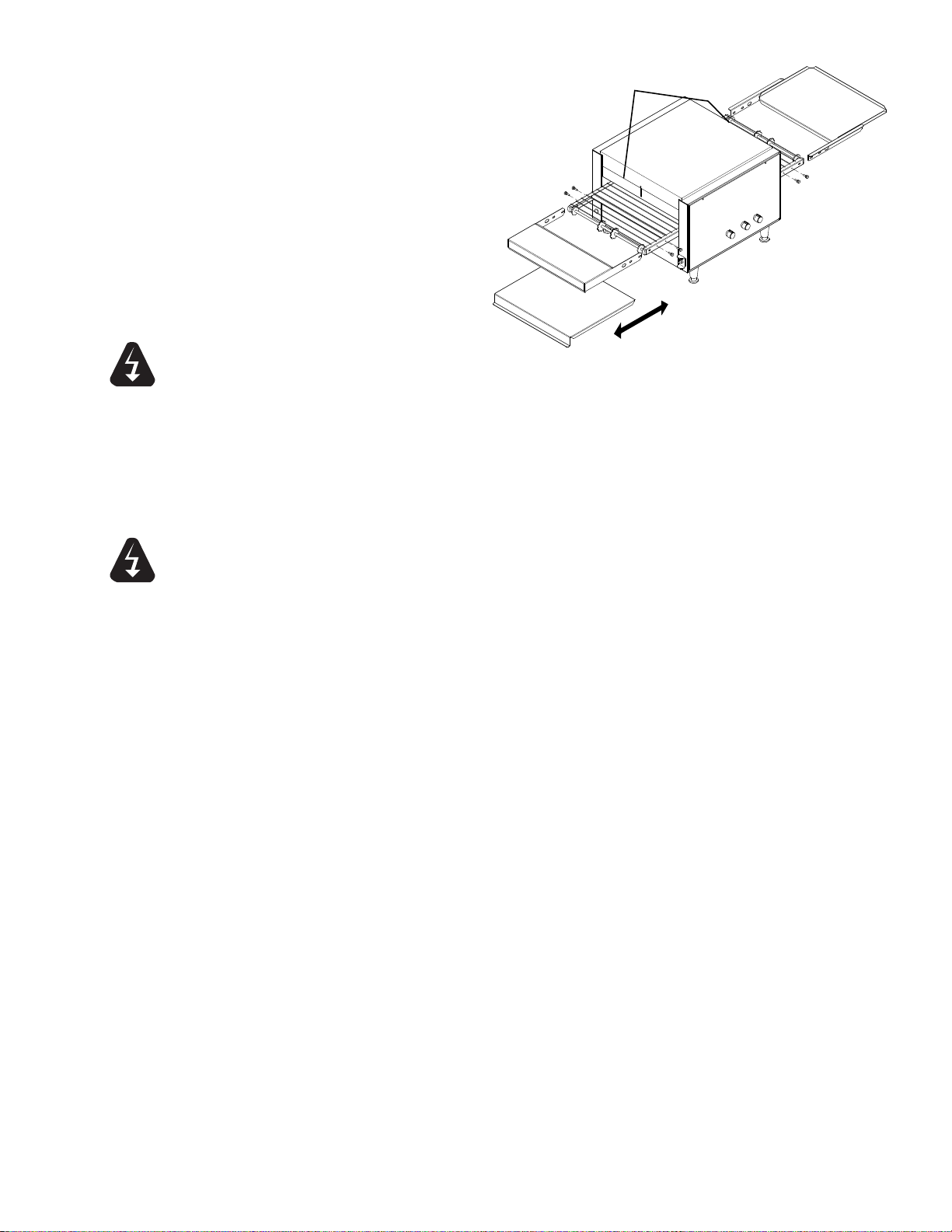
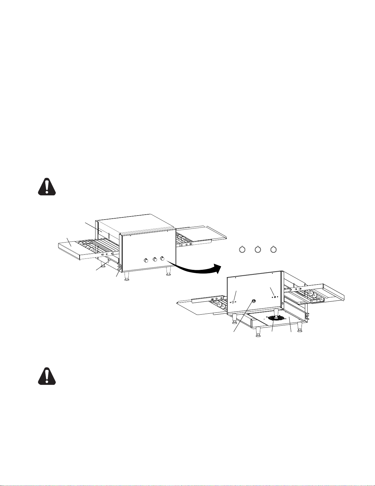
INSPECTION & ASSEMBLY
UNCRATING AND INSPECTING
Unpack the unit and components from the shipping container. Remove all visible packing
material and those from inside the cooking chamber. If damage is discovered, le a claim
immediately with the carrier that handled the shipment. Do not operate the unit if it was damaged
during shipping.
The following should be included: Miniveyor Multi-Purpose Oven, Stainless Steel Load Up &
Unload Trays, 4 Stainless Steel Legs.
CAUTION
CAUTION
REMOVE ALL HEATING ELEMENT SHIPPING SUPPORTS PRIOR TO PLACING
YOUR UNIT INTO OPERATION.
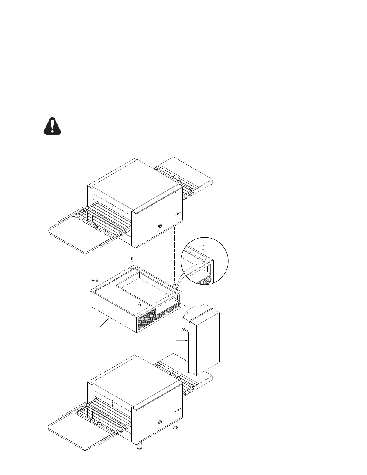
ASSEMBLY AND INSTALLATION
The unit was shipped with certain assembly required, plug into a standard outlet specied for its
voltage and amp draw. If improper electrical supply is determined, contact a qualied electrician
prior to using the unit. Removal and replacement of the power cord and plug will void the
warranty. For assistance, contact your local authorized service agent for service or required
maintenance.
Attach the 4 legs by screwing them into the weld nuts located on the bottom of the unit. When
complete, use two people to
carefully turn the unit upright.
Level unit by adjusting the feet
(approximately 1/2" adjustment).
Never operate unit without proper
legs in place.
Before using the unit for the rst
time, wipe down the exterior with a
damp cloth.
CAUTION
Allow enough space around the oven
for adequate ventilation. Do not
operate the unit without the crumb tray
properly positioned. Overheating and
poor baking may occur. Read all labels
on the unit and follow their instructions.
LEG INSTALLATION
4
Page 5
CLEAN
OPERATE
UNLOAD
TRAY
EXTENDED
NOSE
GUARD
CRUMB TRAY
TYPICAL LEFT TO RIGHT CONFIGURATION
ADJUSTABLE
HEAT SHUTTERS
IL1038
WARNING
ASSEMBLY AND INSTALLATION
continued
Install unit in its operating position allow
sufcient space for operating personnel.
Install the Crumb, Load and Unload Trays
as shown, making sure the ends are at
least 6" from any vertical combustible
surfaces.
Have an electrician connect input power
to the unit(s) in accordance with local
electrical codes. A connection terminal
block is inside the left side cavity for
models not provided with a cord and plug
set.
ELECTRICAL CONNECTION
Before making any electrical connection
to this unit, check that the power supply is adequate for the voltage, amperage and requirements
stated on the rating plate.
A wiring diagram is included herewith.
Disconnect the unit from the power source before installing or removing any parts.
Be absolutely sure that the ground connection for the receptacle is properly wired. Do not connect
equipment to power without proper ground connections. Improper grounding may result in personal
injury or fatality.
WARNING
DO NOT CUT OR REMOVE THIS PLUG OR GROUNDING PRONG FROM THE PLUG.
CONNECT/PLUG UNIT INTO DEDICATED A.C. LINE ONLY SPECIFIED ON THE DATA
PLATE OF THE UNIT.
HEATING ELEMENTS
Inspect all heating elements in the unit for breakage. Every unit is properly tested prior to leaving the
factory, but damage may of occurred during shipping. If a broken tube is found, do not apply power to
the unit. If everything checks out, Turn on Main Power Switch, Turn both heat controls and conveyor
belt speed control to the maximum setting and check all heater tubes and conveyor for proper
operation.
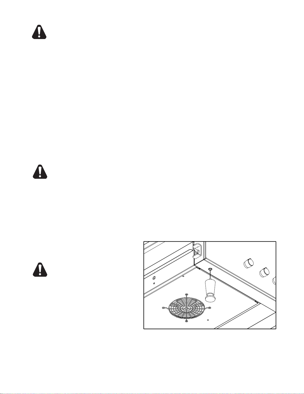
COOLING SYSTEM
After the unit is initially turned on, allow 5 to 8 minutes for the fan cooling system to come on. Once
on, check the air intake area located under the unit and be sure that there is a sufcient ow of air
into the control box. Keep area under the unit clean from obstructions that may result in restricted air
ow to the control box. Restricting the air ow will cause the unit to run hotter then designed, causing
the Hi-Limit to turn unit off. See the Oven Components section on page 7 for control box & Hi-Limit
Reset locations.
FINAL CHECK
If all heaters and conveyor systems are operating properly, switch the master on/off switch to the OFF
position and allow unit to cool, the fan will continue to circulate air, cooling the unit until the internal
temperatures have been decreased.
If a problem is discovered during any of these start-up procedures, immediately switch the master
on/off switch to the OFF position and notify the Star Service Department at (314) 634-6303.
5
Page 6
STACKING OVENS
STACKING SPACER
SET SCREWS
TOP OVEN
BOTTOM OVEN
EXTERNAL AIR
DUCT
IL1037
SET-SCREW
CUT OUTS
When stacking two Holman Miniveyor Ovens a stacking spacer with an external air duct MUST be
used to prevent overheating of the control box of the top oven.
1. Place bottom unit in position where the oven will be located.
2. Place stacking spacer on top of the bottom oven with internal air duct facing up and
towards the rear of the oven.
3. Mount external air duct on stacking spacer as shown below.
External air duct must be installed for cooling system of top unit to function properly.
4. Screw set screws (Qty 4) into leg hole on the top oven.
5. Place top oven on stacking spacer. Set screws will set into cut out in top of stacking
spacer to lock unit into position.
NOTE: Air intake of top unit must t over the internal air duct of stacking
spacer to allow airow into the control box of the top oven.
TOP UNIT:
set screw, screws into leg holes,
unit sits on top of spacer.
STACKING SPACER:
(REQUIRED) Sits on top of bottom
oven.
EXTERNAL AIR DUCT:
Mounts onto spacer, pointing
downward.
BOTTOM UNIT:
Must be placed on a counter in a
secure position.
6
Page 7
UNLOAD TRAY
IL1039
ADJUSTABLE HEAT SHUTTER
(QTY 2)
CONTROL
BOX
HI-LIMIT
SWITCH
R TO L Conv.
POWER
CORD
CRUMB TRAY
AIR INTAKE
FAN
EXTENDED NOSE GUARD
ON/OFF
SWITCH
UPPER
HEAT
CONTROL
LOWER
HEAT
CONTROL
CONVEYOR
SPEED
HI-LIMIT
SWITCH
L TO R Conv.
CAUTION
DAILY OPERATION
Baking in these units is a combination of heat and belt speed. Some foods may require more top heat
or visa versa; other foods may require low top and bottom heat and slow belt speeds. Every product
should, therefore, be tested using the separate top & bottom controls and the variable speed control
to arrive at the correct balance of heat and belt speed. When changing heat and or belt speed setting
allow approx. 5 minutes for the oven to stabilize itself at the new settings.
Check the power cord to insure that it is plugged into a proper outlet.
Always allow 10 to 15 minutes of preheat time before loading the unit with product. Failure to
allow sufcient preheat time will result in unsatisfactory cooking until the cooking chamber reaches
operating temperature. Even though the elements can reach there operating temperature very quickly,
a certain amout of time in needed to allow the cooking chamber to reach its operating temperature.
1) Turn the master on/off switch to the ON position.
2) Set both the top and bottom heat controls to 500°F (260°C).
3) Turn conveyor speed control to the fastest setting.
4) Allow 15-20 minutes for initial warm up,
(5 to 8 minutes to reach adjusted temperature, once unit is fully warmed up)
5) Once the unit is pre-heated, adjust the controls to the proper setting for the product
you are preparing.
CERTAIN SURFACES ARE EXTREMELY HOT DURING OPERATION AND CARE
SHOULD BE TAKEN WHILE USING THIS UNIT.
OVEN COMPONENTS
CAUTION
OPERATING HINTS AND SAFETY
Disconnect power to the unit with the switch at the end of each day of operation.
Do not leave the unit in operation without an attendant.
Do not leave the unit at high temperature when not in use or during idle periods. This will cause food
particles and grease lm to carbonize. Turning the temperature setting down will save energy, It will
take only a few minutes for the unit to regain operating temperature.
7
Page 8
WARNING
IL1040
CAUTION
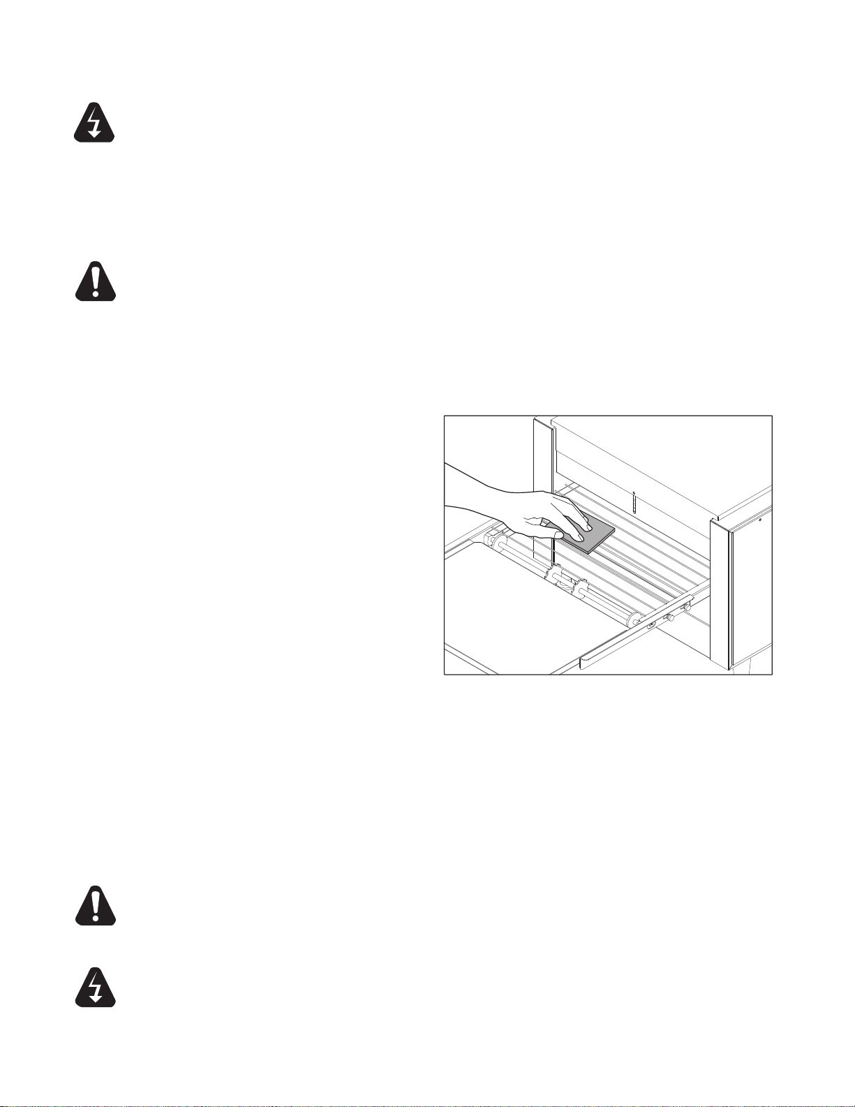
CLEANING
Preventive maintenance for your Holman Oven consists of the following recommended cleaning
procedures. To keep your oven in its top operating condition, these steps should be performed on a
daily, weekly or as indicated.
TURN UNIT OFF, DISCONNECT UNIT FROM POWER SUPPLY OR TURN
POWER OFF AT WALL BREAKER, REMOVE PLUG FROM OUTLET.
DAILY
1. Turn main power switch to the OFF position. Disconnect unit from power source and allow unit to
cool.
2. Using a mild detergent, wipe exterior surfaces, clean with a damp cloth.
a. For lightly soiled build-up, clean with a damp cloth.
b. For heavily soiled build-up, use a soft damp cloth and mild detergent.
DO NOT use caustic cleaners.
3.
Remove the load & unload tray by lifting them out of position. Clean using mild detergent and
warm water.
4. Remove each crumb tray by sliding each of them out from under the conveyor belt.
Clean crumb trays by wiping with a damp cloth and mild detergent.
DO NOT use caustic cleaners. Place trays back in place prior to putting unit back into
operation.
5.
Reconnect power.
WEEKLY
1. Turn main power saver switch to the
OFF position. Disconnect unit from
power source and allow to cool.
2. Perform daily cleaning procedures.
3. Using a damp cloth, wipe clean the fan
guard located on the control box cover
under the unit.
CAUTION
WARNING
CLEAN CONVEYOR BELT
4. Reconnect power or turn power back
on.
5. Switch the ON/OFF switch to the ON
position, and turn Conveyor to its fastest
setting.
6. With the Conveyor turned on and the crumb trays in place, take a wire grill brush or dry
abrasive pad, clean the exposed surface of Conveyor Belt by passing the brush or pad, back and
forth across the surface of the Conveyor Belt as the belt moves past. Continue until the entire
belt is clean. Make sure the Crumb Tray is installed, this will minimize the amount of particles
that fall into the oven.
7. When the Conveyor Belt is clean, take a damp cloth and wipe the conveyor, removing
any loose particles on the belt surface.
8. Remove the Crumb Trays by sliding out from beneath the conveyor belt. Clean the Crumb
Trays by wiping with a damp cloth and mild detergent.
DO NOT use caustic cleaners.
CLEANING CONVEYOR BELT
DO NOT RUN CONVEYOR OVEN WITHOUT CRUMB TRAYS INSTALLED,
OVERHEATING TO ELECTRICAL COMPONENTS AND PREMATURE FAILURE CAN
OCCURE.
DO NOT IMMERSE OR LET THE UNIT STAND IN WATER.
DO NOT HOSE DOWN THE UNIT OR THE TABLE/COUNTER IF THE UNIT IS ON THE
TABLE/COUNTER.
KEEP AWAY FROM RUNNING WATER.
8
Page 9
CLEANING CONTINUED
1.
2.
3.
IL1045
IL1046
DRIVE SPROCKETS
MONTHLY
1. Turn main power switch to the OFF position. Disconnect unit from its power source and allow
to cool.
2. Perform daily & weekly cleaning procedures.
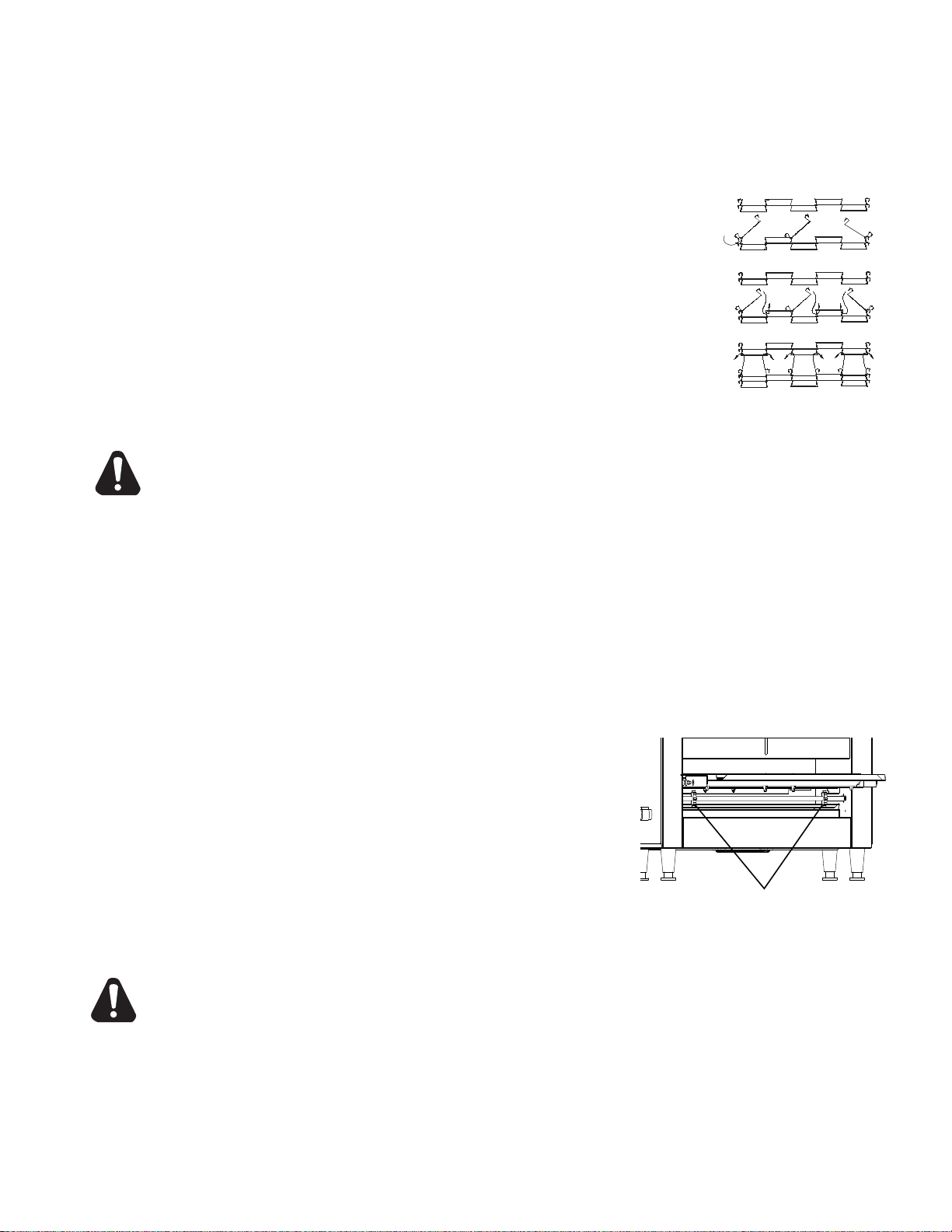
REMOVAL & CLEANING CONVEYOR BELT
3. Heavily soiled conveyor surfaces, 214 models locate all 3 of the
Master Links on the conveyor belt. Follow the step 1 in Fig 1, to
remove all of the Master Links.
210 models have no master links, to remove, unhook each end of one
link and bring the two ends together, and unthread. Once detached,
re-hook onto itself so not to get damaged.
4. Now that the links have been unhooked, the conveyor can now be
carefully removed from the oven. Standing at one end of the oven.
Starting with the end on the bottom, roll the conveyor belt until it has
been totally removed. Take careful notice being sure not to damage
the heater tubes, and working it over the drive sprockets, (see Figure
2).
5. Clean conveyor belt in deep sink, caustic cleaners may be used.
For a heavy soiled conveyor belt, soak over night in hot soapy water.
Fig 1. Master Links
Removal & Installation
CAUTION
NOTE: DO NOT ATTEMPT TO CLEAN THE HEATER TUBES.
6. Take this opportunity to clean and remove any loose materials inside the unit. Using a
mild cleaner and damp cloth, carefully wipe the inside surfaces being sure NOT to clean
the heater tubes.
DAMAGE CAN OCCUR TO THE HEATER TUBES FROM IMPROPER CLEANING.
DO NOT SPRAY CLEANING SOLUTIONS INTO OVEN CAVITY.
7. Reinstall conveyor belt by rst laying the belt along the bottom of the oven cavity making sure
the hooks on the sides are facing the inside and the ends of the hooks will be pointing away
form the direction of the belt so not to catch on any internal components once put back into
operation. Also, being sure to properly align the belt over the Conveyor Drive Sprockets shown
in Fig 2.
NOTE: THE DIRECTION OF THE BELT.
8. Next, pull one end of the conveyor belt over the top of the
sprockets, (being sure to line the links up properly with the
sprockets) bringing the two ends together.
9. 214 models, Reinstall the previously removed master links
as shown in steps 2 & 3 in Fig. 1.
210 Models, unhook the last link of the conveyor, farthest
away from you, and rethread through the other end, and
reconnect back onto itself.
12. Examine the oven to assure proper installation, once
satised, install crumb trays if you have not done so.
DO NOT OPERATE UNIT WITHOUT CRUMB TRAYS INSTALLED.
13. Reconnect oven to power supply and check for proper operation.
Fig 2. Conveyor Drive Sprockets
CAUTION
IF ASSISTANCE IS REQUIRED, CALL THE STAR SERVICE TEAM AT (314) 634-6303.
9
Page 10

MAINTENANCE PROCEDURES
ELEMENT RETAINER
ELEMENT
Control Side Shown
IL1041
IL1042
FAN MOTOR
CONTROL BOX COVER
DRIVE MOTOR
DRIVE SPROCKET
IL1043
A. REPLACING HEATER TUBES
1) DISCONNECT POWER SOURCE.
2) Remove both the left and right side panels,
by removing the truss head screws. Pull the
top of each panel out slightly and lift up.
3) Remove each heater tube wires which
are requiring replacement from its terminal
block connection. One Tube at a Time.
4) Remove heater tube retainer by removing
retainer screws with washer.
5) Gently, pull defective heater tube out of unit.
6) Gently, put new heater tube into unit.
7) Replace heater tube retainers.
8) Reconnect the heater tube wires to the terminal
block.
9) Install each side panel
10) Connect unit to power source and test unit for proper operation.
B. REPLACING FAN MOTOR
1) DISCONNECT POWER SOURCE.
2) After unit has cooled, remove the crumb tray,
and turn unit over so the bottom is facing
upward. Never place unit on its side.
3) Remove the control box cover which contains
the fan motor, by removing the 2 screws.
4) Unplug power supply cord from fan motor.
5) Remove (4) screws, which hold fan motor and grill
to the control box cover and remove fan.
6) Once removed, clean fan grill and control box
cover using warm soapy water.
7) Put replacement motor and grill in place and
secure to the control box cover with screws
previously removed.
8) Reconnect power supply cord to fan motor.
9) Replace back panel and enclosure. Fasten with
screws removed in step 3.
10) Connect unit to power source, reinstall the crumb
tray and test unit for proper operation.
C. REPLACING BELT DRIVE MOTOR
1) DISCONNECT POWER SOURCE.
2) After unit has cooled, remove the crumb tray,
and turn unit over so the bottom is facing
upward. Never place unit on its side.
3) Remove the control box cover which contains
the fan motor, by removing the (2) screws.
4) Remove the side panel that will expose the
drive chain and sprockets.
5) Remove sprocket from motor shaft, using an
Allen wrench and loosening the set-screw.
6) Remove the wire from terminal block connecting
the drive motor to the internal wiring.
On units rated 208 or 240 volts, note which
color leads are being used for these connections
and which lead is capped with glass tape. The
new motor should use the same arrangement.
Reference the wiring diagram if needed.
7) Remove screws holding motor in place and
remove motor from unit.
8) Put new motor in place and attach loosely with mounting screws.
9) Replace sprocket on motor shaft.
NOTE: The two sprockets must line up FLUSH with each other, so the chain does not twist any during
operation. Also the hub gets installed closets to the motor.
10
Page 11

MAINTENANCE PROCEDURES continued
IL1044
SPEED CONTROL
WASHER
INSTALLATION
LOCKING NUT
KNOB
SIDE PANEL
1/4”
10) Slide motor until the drive chain has about 1/4” slack when
lightly pushed at the center of its top open run.
See chain tensioning illustration.
11) Tighten screws to secure motor.
12) Rewire leads same as removed in step 6.
13) At this time you may plug unit in and test for proper operation prior
to reinstalling panels and turning unit back over onto its feet.
14) If unit is working correctly, turn unit off and unplug until completed.
15) Reinstall side panels and control box cover.
Place unit back into its upright position.
Reinstall the crumb tray.
16) Connect unit to power source and test unit for proper operation.
D. REPLACING SPEED CONTROL
1) DISCONNECT POWER SOURCE.
2) Remove the speed control knob and the locking
nut holding the speed control in place.
3) Remove right side panel, by removing the truss
head screws. Pull the top of the panel out slightly
and lift up.
4) Wires from the speed control go into a terminalblock
located on the side of the chassis. Remove the wires
from the control and insert wires for the new speed
control into the same positions as shown on the wiring
diagram.
5) Install the washer onto the shaft of the speed control,
followed by the installation.
6) When mounting the speed control in the side panel
be sure to position the anti-rotation pin in the slot as
shown.
7) Tighten the speed control assembly by using the
locking nut, followed by the control knob.
8) Reinstall the side panel and tighten with the screws previously removed.
Chain Tension
E. CLEANING AIR INTAKE ONCE A WEEK.
1) DISCONNECT UNIT FROM POWER SOURCE.
2) Place unit upside down. NOTE: You may damage the Heatertubes, by placing unit on its side.
3) Use a vacuum cleaner and or a damp cloth to clean the air intake.
This procedure should be done at least once a week.
F. LUBRICATE THE CHAIN & SPROCKETS EVERY 6 MONTHS
1) DISCONNECT UNIT FROM POWER SOURCE.
2) Remove the side panels which exposes chain drive.
3) Using an extreme pressure, synthetic chain lubricant with a temperature range up to 400°F.
Apply liberally onto chain and sprockets.
This grease is available separately as part no. 1P-Z8914. Call (314) 678-6303 to order.
4) Replace side panels, Reconnect power source and test unit.
11
Page 12

TROUBLESHOOTING GUIDE
DRIVE SPROCKET
CHAIN
IL1047
DRIVEN
SPROCKET
A. UNIT WILL NOT HEAT, CONVEYOR BELT WILL NOT MOVE.
1) Be sure the main circuit breaker is switched to the ON position and there is power to the outlet.
2) Check to see if the oven is plugged in and all controls are turned to the ON position.
3) Be sure the Hi-Limit Reset Button is pushed in.
4) Call the Star Service Help Desk at (314) 634-6303.
B. UNIT WILL NOT HEAT, CONVEYOR TURNS PROPERLY.
1) Check to see if the top and bottom heat controls have been turned to the maximum setting.
2) Press the Hi-Limit Reset Button located underneath the conveyor belt on the inlet side. If this reactivates
the heater tubes, see Hi-Limit Reset Section below.
3) If not, call the Star Service Help Desk at (314) 634-6303.
C. HI-LIMIT (HEAT) RESET.
Your Holman conveyor oven is equipped with an automatic activated temperature limit switch which interrupts the
heater tube connections if the air temperature in the control box exceeds 190°F (88°C) This limit switch can be
reset manually by pushing the button in the center of the switch which is located on the power cord side panel, on
older models its on the right side under the conveyor belt. See Oven Components on Page 7 for location. Unit
will not reset until internal temperature has fallen below 190°F (88°C).
NOTE: THE HI-LIMIT SWITCH CAN BE ACTIVATED IF THERE IS NOT A PROPER AMOUNT OF
AIR FLOW BEING GENERATED BY THE COOLING FAN. IF THIS OCCURS:
1) DISCONNECT UNIT FROM POWER SOURCE.
2) Check to see if the air intake area (center of the control box, bottom of unit) is free of dust,
grease or other obstructions.
3) Check to see if crumb trays (heat reectors) are in place. If the Hi-Limit Switch can not be reset, call the
Star Service Help Desk at (314) 634-6303.
CAUTION
NEVER OPERATE UNIT WITHOUT CRUMB TRAYS IN POSITION AS THIS CAUSES
OVERHEATING IN THE CONTROL BOX.
D. CONVEYOR WILL NOT TURN, UNIT HEATS PROPERLY.
To check for mechanical binding:
1) DISCONNECT UNIT FROM POWER SOURCE.
2) Check to see if there are obstructions in the conveyor
system that may cause a jam.
If so, remove obstruction.
3) Check power supply & terminal blocks for loose or
disconnected wires.
4) Remove right side panel and drive motor sprockets,
see illustration. Manually move conveyor belt to
check for mechanical binding. If conveyor belt moves
freely, call the Star Service Help Desk at (314) 634-
6303. The drive motor or speed control may have to
be replaced.
E. CONVEYOR TURNS AT ONE SPEED
REGARDLESS OF SPEED CONTROL SETTING.
1) Call the Star Service Help Desk at (314) 634-6303, as speed control MAY need replacing.
Refer to REPLACING SPEED CONTROL in the previous section.
F. COOLING FAN DOES NOT START
1) Remove control box cover and check fan blade for obstruction.
2) Check electrical connections are secure and complete.
3) Call the Star Service Help Desk at (314) 634-6303, as the fan switch and or fan motor MAY need
replacing.
Refer to REPLACING FAN MOTOR in the previous section.
12
Page 13

WIRING DIAGRAMS
Temp Control
Phase Control
IL1048
Temperature Probe
Fan Switch
3 Wired Potentiometer
2 Wired Potentiometer
TEMP CONTROL PHASE CONTROL
Fan Switch
Pilot Light
All wiring diagrams on the following pages are those of current and obsolete design models, and
may not represent current production. To determine which diagram goes with your unit, reference
the nameplate located on the cord side of the unit, and use the table below.
Call the Star Service Help Desk at (314) 634-6303, if you have questions, or unable to determine
your models diagram.
WIRING DIAGRAMS TABLE OF CONTENTS
DESCRIPTION PAGE
210HX/214HX, 120V, 50/60Hz, 4-Tube, Wired Series 14
210HX, 120V, 60Hz, 4-Tube, Wired Series, Canada 15
210HX/214HX, 208/220/240V, 50/60Hz, 3.2Kw, 4-Tube, Wired Series 15
214HX, 220V, 50/60Hz, 3.6Kw, 4-Tube, Wired Series 15
214HX, 208V, 60Hz, 4.0Kw, 4-Tube, Wired Series 15
214HX, 208V, 60Hz, 4.5Kw, 4-Tube, Wired Series 15
210HX, 120V, 60Hz, 4-Tube, Wired Parallel 16
214HX, 240V, 50Hz, 4-Tube, Wired Parallel 16
214HXR, 240V, 50Hz, 4.5Kw, 4-Tube, Wired Parallel 16
214HX, 208/240V, 50/60Hz, 3.6Kw, 4-Tube, Wired Parallel 16
214HX, 208/220/240V, 50/60Hz, 5-Tube, Wired Parallel 17
214HX, 208/220/240V, 50/60Hz, 4.0Kw, 5-Tube, Wired Parallel 17
214HX, 208V, 60Hz, 4.5Kw, 5-Tube, Wired Parallel 17
214HX, 208/240V, 60Hz, 4.5Kw, 6-Tube, Wired Parallel 18
210/214HX, 208/240V, 50Hz, CE, 4-Tube, Wired Series 19
210/214HX, 208/240V, 50Hz, 4-Tube, Wired Parallel 20
HEAT CONTROLS
There is one control for each heat control knob.
These are located in the control box.
To determine what type of heat controls your
unit is equipped with, follow these easy
instructions.
1. If your unit is equipped with a Pilot Light your unit
is a Temp Control unit, if it does not have a Pilot
Light, you have a Phase Contol unit.
13
Page 14

®
MODEL:
210HX, 120V, 50/60Hz, 4-Tube, Wired Series
214HX, 120V, 60Hz, 4-Tube, Wired Series
THIS DRAWING CONTAINS INFORMATION CONFIDENTIAL TO STAR MFG. INT'L. INC.
NO REPRODUCTION OR DISCLOSURE OF ITS CONTENTS IS PERMITTED.
020022 Rev B
9/22/2009
GND
HEAT
ADJUST
HEAT
ADJUST
CONVEYOR
MOTOR
HIGH
LIMIT
SWITCH
POWER ON/OFF
FAN
CONTROL
FAN
MOTOR
SPEED CONTROL
GND
L1
L2
AS SHOWN ABOVE FOR
CORD SUPPLIED UNITS
BLACK
WHITE
GROUND
L2
L1
Top Heat
Bottom Heat
BLU
YEL
ORG
ORG
BLU
BLK
BLK
RED
RED
YEL
RED
BLU
BLK
PUR
BLK
WHT
RED
BLU
BLU
BLK
RED
BLK
BLK
BLK
14
Page 15

RED
RED
YEL
ORG
BLU
BLU
YEL
BLK
YEL
BLK
WHT
PUR
BLK
WHT
BLK
RED
BLK
RED
BLK
BLK
BLK
BLU
RED
WHT
WHT
BLK
®
MODELS:
210HX, 120V, 60Hz, 4-Tube, Wired Series, Canada
210HX(P)/214HX, 208,220,240V, 50/60Hz, 3.2 Kw, 4-Tube, Wired Series
214HX, 220V, 50/60Hz, 3.6 Kw, 4-Tube, Wired Series
214HX, 208V, 60Hz, 4.0 Kw, 4-Tube, Wired Series
214HX, 208V, 60Hz, 4.5 Kw, 4-Tube, Wired Series
214HXBM, 240V, 60Hz, 4.5Kw, 4-Tube, Wired Series
THIS DRAWING CONTAINS INFORMATION CONFIDENTIAL TO STAR MFG. INT'L. INC.
NO REPRODUCTION OR DISCLOSURE OF ITS CONTENTS IS PERMITTED.
020001 Rev C
9/16/08
GND
HEAT
ADJUST
HEAT
ADJUST
CONVEYOR
MOTOR
HIGH
LIMIT
SWITCH
POWER ON/OFF
FAN CONTROL
FAN
MOTOR
SPEED CONTROL
AS SHOWN ABOVE FOR
CORD SUPPLIED UNITS
BLACK
(brown*)
WHITE
(blue*)
GROUND
L2
L1
*2E-Y9002 Shuko plug
15
Page 16

BLK
RED
HIGH LIMIT
SWITCH
RED
RED
RED
GROUND
Top Heat
Bottom Heat
BLU
YEL
HEAT
ADJUST
ORG
ORG
YEL
WHT
PUR
BLK
BLK
BLK
BLK
BLK
BLU
WHT
WHT
BLK
®
MODEL:
210HX, 120V, 60Hz, 4-Tube, Wired Parallel
214HX, 240V, 50Hz, 4-Tube, Wired Parallel
214HXR, 240V, 50Hz, 4.5Kw, 4-Tube, Wired Parallel
214HX, 208/240V, 50/60Hz, 3.6Kw, 4-Tube, Wired Parallel
THIS DRAWING CONTAINS INFORMATION CONFIDENTIAL TO STAR MFG. INT'L. INC.
NO REPRODUCTION OR DISCLOSURE OF ITS CONTENTS IS PERMITTED.
020014 Rev A
11/17/2005
208/240 VAC
240 VAC
16
Page 17

17
Page 18

ORG
BLU
WHT
ORG
YEL
BLU
BLU
RED
BLK
ORG
BLK
BLK
BLK
BLK
WHT
BRN
RED
RED
RED
BLK
YEL
®
MODEL:
214HX, 208/240V, 60Hz, 4.5Kw, 6-Tube, Wired Parallel
THIS DRAWING CONTAINS INFORMATION CONFIDENTIAL TO STAR MFG. INT'L. INC.
NO REPRODUCTION OR DISCLOSURE OF ITS CONTENTS IS PERMITTED.
020175 Rev -
9/11/2002
1
3
4
1
3
4
M
M
DRIVE MOTOR
FAN MOTOR
ON/OFF SWITCH
RESET
SPEED CONTROL
BOTTOM HEAT
TOP HEAT
L1
L2
GROUND
FAN SWITCH
HEAT
ADJUST
ADJUST
HEAT
TOP HEAT
BOTTOM HEAT
18
Page 19

Pilot
Light
Non-Cord
Supplied Units
L1
L2
GND
High-Limit
Switch
AS SHOWN ABOVE FOR
CORD SUPPLIED UNITS
BLACK
WHITE
GROUND
L2
L1
TOP HEAT
FAN
BOTTOM HEAT
RED
RED
RED
ORN
WHT
BLK
BLK
WHT
YEL
BLK
BLK
BRN
BLK
BLK
BLK
BLK
BLK
BLK
RED
RED
ORG
BLU
WHT
ORG
PUR
ORG
YEL
PUR
YEL
WHT
WHT
WHT
WHT
ORG
PUR
ORG
YEL
PUR
YEL
WHT
WHT
WHT
®
MODEL:
210/214HX, 208/240V, 50Hz, CE, 4-Tube, Wired Series
THIS DRAWING CONTAINS INFORMATION CONFIDENTIAL TO STAR MFG. INT'L. INC.
NO REPRODUCTION OR DISCLOSURE OF ITS CONTENTS IS PERMITTED.
820019 Rev. C
6/23/2006
19
Page 20

®
MODEL:
210HX/214HX, 208/240V, 50Hz, 4-Tube, Wired Parallel
THIS DRAWING CONTAINS INFORMATION CONFIDENTIAL TO STAR MFG. INT'L. INC.
NO REPRODUCTION OR DISCLOSURE OF ITS CONTENTS IS PERMITTED.
820039 Rev -
2/07/2001
Top Heat
Bottom Heat
M
Main Power
or Cordset
M
Conveyor
Motor
Power
On / Off
BOTTOM
HEAT
CONTROL
Speed
Control
High Limit
Reset
BOTTOM TEMP. PROBE
FAN
TOP TEMP. PROBE
CONTROL
TOP
HEAT
PILOT LIGHT
RED
RED
BLK
BLK BLK
BLK
BLK
BLK
RED
WHT
WHT
ORG
BLU
BLK
BLK
BLK
BLK
BLK
BLK
BRN
RED
RED
ORG
ORG
YEL
PUR
YEL
PUR
WHT
ORG
YEL
PUR
YEL
PUR
ORG
WHT
WHT
WHT
WHT
WHT
WHT
WHT
YEL
BLK
BLK
WHT WHT
YEL
20
Page 21

Visit our Website at: www.star-mfg.com Email: service@star-mfg.com
This unit has been tested for proper operation before leaving our plant to insure delivery of your unit in perfect condition. However, there are instances in which
the unit may be damaged in transit. In the event you discover any type of damage to your product upon receipt, you must immediately contact the transportation
company who delivered the item to you and initiate your claim with same. If this procedure is not followed, it may affect the warranty status of the unit.
All workmanship and material in Star products have a one (1) year limited warranty on parts & labor in the United States and Canada. Such warranty is limited
to the original purchaser only and shall be effective from the date the equipment is placed in service. Star's obligation under this warranty is limited to the repair
of defects without charge, by the factory authorized service agency or one of its sub-agencies. Models that are considered portable (see below) should be taken
to the closest Star service agency, transportation prepaid.
THOROUGHLY INSPECT YOUR UNIT ON ARRIVAL
LIMITED EQUIPMENT WARRANTY
> Star will not assume any responsibility for loss of revenue.
> On all shipments outside the United States and Canada, see International Warranty.
* The warranty period for the Ultra-Max, Hot Plates, Griddles, Charbroilers is (3) years parts & labor.
* The warranty period for the Star-Max, Charbroilers, Griddles, Hot Plates, Fryers & Finishing Oven is (2) years parts & labor.
* The warranty period for the JetStar six (6) ounce & Super JetStar eight (8) ounce series popcorn machines is two (2) years.
* ThewarrantyperiodfortheChrome-MaxGriddlesisve(5)yearsonthegriddlesurface.Seedetailedwarrantyprovidedwithunit.
* ThewarrantyperiodforTeon/Dura-Teccoatingsisoneyearundernormaluseandreasonablecare.Thiswarrantydoesnotapplyifdamageoccursto
Teon/Dura-Teccoatingsfromimpropercleaning,maintenance,useofmetallicutensils,orabrasivecleaners,abrasivepads,productidentiersand
point-of-sale attachments, or any other non-food object tha comes in continuous contact with the roller coating. This warranty does not apply to the
“non-stick” properties of such materials.
> This warranty does not apply to "Special Products" but to regular catalog items only. Star's warranty on "Special Products" is six (6) months on parts
and ninety (90) days on labor.
> This warranty does not apply to any item that is disassembled or tampered with for any purpose other than repair by a Star Authorized Service Center or
the Service Center's sub-agency.
> This warranty does not apply if damage occurs from improper installation, misuse, wrong voltage, wrong gas or operated contrary to the Installation and
Operating instructions.
> This warranty is not valid on Conveyor Ovens unlessa"start-up/check-out"hasbeenperformedbyaFactoryAuthorizedTechnician.
Parts that are sold to repair out of warranty equipment are warranted for ninety (90) days. The part only is warranted, the labor to replace the part is NOT warranted.
1. Traveltimeandmileagerenderedbeyondthe50mileradiuslimit
2. Mileage and travel time on portable equipment (see below)
3. Labor to replace such items that can be replaced easily during a daily cleaning
routine, ie; removable kettles on fryers, knobs, grease drawers on griddles, etc.
4. Installation of equipment
5. Damagesduetoimproperinstallation
6. Damages from abuse or misuse
7. Operated contrary to the Operating and Installation Instructions
8. Cleaning of equipment
9. Seasoning of griddle plates
Star will not honor service bills that include travel time and mileage charges for servicing any products considered "Portable" including items listed below.
These products should be taken to the Service Agency for repair:
* TheModel510FD,510FFFryer.
* TheModel526TOAToasterOven.
* TheModelJ4R,4oz.PopcornMachine.
*TheModel518CMA&526CMACheeseMelter.
* TheModel12MC&15MC&18MCPHotFoodMerchandisers.
* TheModel12NCPW&15NCPWNachoChip/PopcornWarmer.
* All Hot Dog Equipment except Roller Grills & Drawer Bun Warmers.
* All Nacho Cheese Warmers except Model 11WLA Series Nacho Cheese Warmer.
* All Condiment Dispensers except the Model HPD & SPD Series Dispenser.
* All Specialty Food Warmers except Model 130R, 11RW Series, and 11WSA Series.
* AllQCS/RCSSeriesToastersexcept Model QCS3 & RCS3 Series.
* All Fast Steamer Models except Direct Connect Series.
SERVICES NOT COVERED BY WARRANTY
PARTS WARRANTY
10. Voltage conversions
11. Gas conversions
12. Pilot light adjustment
13. Miscellaneous adjustments
14. Thermostat calibration and by-pass adjustment
15. Resettingofcircuitbreakersorsafetycontrolsorresetbuttons
16. Replacementofbulbs
17. Replacementoffuses
18. Repairofdamagecreatedduringtransit,delivery,&
PORTABLE EQUIPMENT
installationORcreatedbyactsofGod
ALL:
* Pop-Up Toasters
* Butter Dispensers
* Pretzel Merchandisers
(Model 16PD-A Only)
* Pastry Display Cabinets
* Nacho Chip Merchandisers
* Accessories of any kind
* Sneeze Guards
* Pizza Ovens
(Model PO12 Only)
* Heat Lamps
* Pumps-Manual
The foregoing warranty is in lieu of any and all other warranties expressed or implied and constitutes the entire warranty.
FOR ASSISTANCE
Should you need any assistance regarding the Operation or Maintenance of any Star equipment; write, phone, fax or email our Service Department.
In all correspondence mention the Model number and the Serial number of your unit, and the voltage or type of gas you are using.
2M-4497-2 6/1312
Page 22

20
®
21
7
9
10
18
17
19
SK2150 Rev. B 9/14/09
16
15
11
14
23
13
Phase
12
33
22
34
35
8
25
7
6
11
24
Temp
26
5
27
4
3
28
32
29
1
Nameplate
43
42
30
10
2
11
12
11
31
36
37
38
39
40
41
210HX, 214HX
MODEL: MINIVEYOR
44
Page 23

Description
Per
Quantity
No.
Part
Fig
No.
27 2E-200543 1 On/Off Switch
28 2R-200716 4 Legs, 2½”
29 2P-401780 1 Guard, Toggle Switch
30 2J-200427 1 Pilot Light CE Only
32 2U-200559 1 Fan Motor 120V
2U-200561 1 Fan Motor
33 GA-401499 1 Control Box Cover
34 2R-200562 1 Fan Grill
35 2C-Z5883 4 Screw, Fan Grill
36 GA-401097 1 Extended Nose Guard
37 HM-416962 1 Crumb Tray
38 GA-160001 1 Conveyor Belt, 10” wide
40 2E-200566 1 Reset Switch
41 GB-Z 1 Side Panel, L-R (cord) w/side Hi-Limit 12/3 Cord Set
GB-Z10058-2 1 Side Panel, R-L (cord) w/side Hi-Limit 12/3 Cord Set
GB-Z10055 1 Side Panel, L-R (cord) w/side Hi-Limit 14/3, 16/3 Cord Set
GB-Z10055-2 1 Side Panel, R-L (cord) w/side Hi-Limit 14/3, 16/3 Cord Set
GB-401524 1 Side Panel, (cord) w/o side Hi-Limit
GB-Z9862 1 Side Panel, (cord) HXETB
42 2K-Y6764 1 Bushing, Cord 12/3 Cord Set
2K-Y2968 1 Bushing, Cord 14/3 & 16/3 Cord Set
43 2E-200375 1 Cord Set, 14/3 120V
2E-200376 1 Cord Set, 14/3 208/240V
2E-Y9002 1 Cord Set, 16-3 CE Approved
210HX Series Holman Conveyor Oven
Description
Per
Quantity
NI = NOT ILLUSTRATED,
NI 2C-200773 1 Button Plug
NI 2E-200387 1 Cord, Cooling Fan
NI 2P-115501 AR Jumpers (2 Position)
NI 2P-115502 AR Jumpers (3 Position)
NI GE-115503 AR Jumpers (4 Position)
NI HA-115383 AR Block, Terminal (3 Position)
NI HC-115381 AR Block, Terminal (4 Position)
NI HK-115388 AR Block, Terminal (6 Position)
NI HB-115387 AR Block, Terminal (8 Position)
NI H9-Z10282 AR Block, Terminal (10 Position), SMALL
NI 1L-Z12397 1 Extreme Pressure Multipurpose Synthetic Grease
AR = AS REQUIRED
(80°F TO 400°F) , TUBE 1 oz.
No.
Part
Fig
No.
1 GA-401287 1 Top Cover
2 HM-400891 2 Heat Shutter
3 2P-150001 1 Drive Chain, 12 in.
4 2P-Z8779 1 Sprocket, 25P-11T 5/16 ID, Drive
2P-200646 1 Sprocket, 25B20 x 5/16, Drive 210HXRC-V01
5 2P-200653 1 Sprocket, 25B20 x 3/8, Driven
2P-115362 1 Sprocket, 25B11 x 3/8, Driven 210HXRC-V01
6 2U-Z13803 1 Drive Motor, (L-R) 120V
2U-Z13804 1 Drive Motor, (R-L) 120V
2U-Z11871 1 Drive Motor, (R-L), CCW 208/240V
2U-Z11870 1 Drive Motor, (L-R), CW 208/220/240V
7 HA-112261 2 Bearings
8 2A-100906 1 Drive Shaft
9 GA-101401 1 Unload Tray
10 2C-200015 8 Screws, 8-32x3/8 Knurled
11 2P-200693 4 ExtensionBushing,Teon
12 2A-202904 2 Idler Shaft
13 SEE ELEMENT CHART
14 GA-402129 4 Retainers, Heater Tube (Quartz)
GB-402444 6 Retainers, Heater Tube (Metal)
15 SP-115341 1 Heat Control Assy. (Bot) 120V
SP-115343 1 Heat Control Assy. (Bot)
2J-200567 1 Heat Control Assy. (Bot) CE
16 SP-115340 1 Heat Control Assy. (Top) 120V
SP-115342 1 Heat Control Assy. (Top)
2J-200567 1 Heat Control Assy. (Top) CE
17 SP-118002 1 Speed Control 120V
GB-118062 1 Speed Control
18 2E-200180 3 Insulation, Switch Pot.
19 GB-401328 1 Side Panel, (controls)
20 2M-200818 1 Control Label
21 SP-115360 3 Knob Assembly
2R-200708 3 Cap, Knob (included in #21)
2R-200713 3 Skirt, Knob (included in #21)
2R-200768 3 Knob Control (Included in #21)
22 SP-115338 2 Control, Phase 120V
SP-115339 2 Control, Phase
SP-115347 2 Control, Temp CE Only
23 2J-200568 2 Heat Probe CE Only
24 1P-E1299 12inches Edging, 16-18 GA. SS (for both holes)
Rev. J 5/23/2013
25 HG-402144 1 Fan Switch Bracket
26 2E-200574 1 Fan Switch
Page 24

Description
Per
Quantity
No.
Part
Fig
No.
23 2J-200568 2 Heat Probe CE Only
24 1P-E1299 12in Edging, 16-18 GA. SS (for both holes)
25 HG-402144 1 Fan Switch Bracket
26 2E-200574 1 Fan Switch
27 2E-200543 1 On/Off Switch
28 2R-200716 4 Legs, 2½”
29 2P-401780 1 Guard, Toggle Switch
30 2J-200427 1 Pilot Light, CE Only
31 2E-Z8966 1 Contactor; Relay
32 2U-200561 1 Motor, Fan 240V 23BTM
32 2U-200559 1 Motor, Fan 120V 12A12-BTM 120V
33 HM-401498 1 Control Box Cover
34 2R-200562 1 Fan Grill
35 2C-Z5883 4 Screw, Fan Grill
36 HM-401096 1 Extended Nose Guard
37 HM-402787 1 Crumb Tray
38 GB-160007 1 Conveyor Belt, 14” Wide
39 2B-200603 3 Master Links 214HX
40 2E-200566 1 Reset Switch
41 GB-Z10058 1 Side Pnl, L-R (cord) w/side Hi-Limit 12/3 Cord Set
GB-Z10058-2 1 Side Pnl, R-L (cord) w/side Hi-Limit 12/3 Cord Set
GB-Z10055 1 Side Pnl, L-R (cord) w/side Hi-Limit 14/3, 16/3 Cord Set
GB-Z10055-2 1 Side Pnl, R-L (cord) w/side Hi-Limit 14/3, 16/3 Cord Set
GB-401524 1 Side Pnl, (cord) w/o side Hi-Limit
GB-Z9862 1 Side Pnl, (cord) HXETB, HXRETB
214HX Series Holman Conveyor Oven
Description
Per
Quantity
42 2K-Y6764 1 Bushing, Cord 12/3 Cord Set
2K-Y2968 1 Bushing, Cord 14/3 & 16/3 Cord Set
43 2E-200375 1 Cord Set, 14/3 120V
2E-200376 1 Cord Set, 14/3 208/220/240V
2E-200374 1 Cord Set, 12/3 208/220/240V
2E-Y9002 1 Cord Set, 16/3 220/240V CE Approved
HG-Z16423 1 Cord Set, BS 546 214HXA-V28
44 2E-30901-08 2 Fuse Hldr for SC Fuse
2E-Z5680 2 FUISE - CLASS G (5amp)
NI 2E-200387 1 Cord, Cooling Fan
NI 2P-115501 AR Jumpers (2 Position)
NI 2P-115502 AR Jumpers (3 Position)
NI GE-115503 AR Jumpers (4 Position)
NI HA-115383 AR Block, Terminal (3 Position)
NI HC-115381 AR Block, Terminal (4 Position)
NI HK-115388 AR Block, Terminal (6 Position)
NI = NOT ILLUSTRATED, AR = AS REQUIRED
NI HB-115387 AR Block, Terminal (8 Position)
NI 1L-Z12397 1 Multipurpose Synthetic Grease (80°F TO 400°F) , tube 1 oz.
No.
Part
Fig
No.
1 GB-401288 1 Top Cover
2 HM-400899 2 Heat Shutter
3 2P-150001 1 Drive Chain, 12 in.
4 2P-Z8779 1 Drive Sprocket (11 tooth) .313 ID
2P-200646 1 Drive Sprocket (20 tooth) 214HXRC, HXETB, HXR
2P-200653 1 Drive Sprocket (20 tooth) 214HXRRCM, 214HXRCM
2P-Z8779 1 Drive Sprocket (11 tooth) 214HXARC
5 2P-200653 1 Driven Sprocket
2P-115362 1 Driven Sprocket (11 tooth) 214HXRC, HXARC, HXETB, HXR
2P-Z8779 1 Driven Sprocket (11 tooth) 214HXRRCM, 214HXRCM
6 2U-Z11871 1 Drive Motor, (R-L), CCW 214HXR
2U-Z11870 1 Drive Motor, (L-R), CW 214HXR, HXRRCM, HXRCM
2U-Z13803 1 Motor, Drive 120V (L-R) CW 120V
2U-200590 1 Drive Motor, 3286 BB 220V, 50Hrz
7 GB-112262 2 Bearings
8 2A-100907 1 Drive Shaft
9 GB-101402 1 Unload Tray
10 2C-200015 8 Screws, 8-32x3/8 Knurled
11 2P-200693 4 Extension Bushing
12 2A-202905 2 Idler Shaft
13 SEE ELEMENT CHART
14 GB-402245 6 Retainers, Quartz Elements
GB-402444 6 Retainers, Metal Elements
GA-402129 4 Retainer, Quartz Elements CE Only
GB-Z9864 1 Retainer, 6 Metal Elements HXETB, HXRETB
15 SP-115341 1 Heat Control Assy. (Bottom) 120V
SP-115343 1 Heat Control Assy. (Bottom) 208/220/240V
2J-200567 1 Heat Control Assy. (Bottom) TEMP CE Only
16 SP-115340 1 Heat Control Assy. (Top) 120V
SP-115342 1 Heat Control Assy. (Top) 208/220/240V
2J-200567 1 Heat Control Assy. (Top) TEMP CE Only
17 GB-118062 1 Speed Control
18 2E-200180 3 Insulation, Switch Pot.
19 GB-401328 1 Side Pnl, (controls)
19 GB-Z9861 1 Side Pnl, (controls) mfg before 11/07HXETB, HXRETB
20 2M-200818 1 Control Label
2M-200819 1 Control Label 214HXALT
2M-Z9876 1 Control Label 214HXRC, HXETB, HXR
21 SP-115360 3 Knob Assembly
2R-200708 3 Cap, Knob (included in #21)
2R-200713 3 Skirt, Knob (included in #21)
2R-200768 3 Knob Control (Included in #21)
Rev. J 5/23/2013
22 SP-115339 2 Control, Phase
SP-115347 2 Control, Temp CE Only
Page 25

Draw
Unit Amp
19.3
13.1
11.5
210HX
214HX
ELEMENT CHART
210HX & 214HX Series Element Chart
Fig. No Part No Qty Desc Unit Voltage
GA-199100 NLA 4 Heater Tube (430W, 3.58A) 120V (Metal) 14.3
GH-197848 4 Heater Tube (7.86Ω, 425W, 3.54A) 120V (Quartz) 14.2
2N-209197 4 Heater Tube (700W, 3.36A) 208V (Metal) 13.4
HO-197841 4 Heater Tube (14.5Ω, 700W, 3.36A) 208V (Quartz) 13.4
HT-197845 4 Heater Tube (800W, 3.84A) 208V (Quartz) 15.4
13
HO-197844 4 Heater Tube (15.84Ω, 700W, 3.18A) 220V (Quartz) 12.7
HT-197846 4 Heater Tube (800W, 3.63A) 220V (Quartz) 14.5
HO-199106 4 Heater Tube (700W, 2.91A) 240V (Metal) 11.6
HO-197842 4 Heater Tube (19.2Ω, 700W, 2.91A) 240V (Quartz) 11.6
HT-187847 4 Heater Tube (800W, 3.33A) 240V (Quartz) 13.3
GC-197855 4 Heater Tube (16.66Ω, 432W, 3.6A) 120V (Quartz) 14.4
Heater Tube (51.02Ω, 800W, 3.85A) 208V (Metal)
5
2N-Z11215* 5 Heater Tube (51.02Ω, 800W, 3.85A) 208V (Metal Extended) HXETB & HXRETB 19.2
2N-209130
6 23.1
3
Heater Tube (59.0Ω, 909W, 4.37A) 208V (Quartz)
4 17.5
HT-197851
5 21.9
HT-197845 4 Heater Tube (104V, 810W, 3.89A) Series 208V (Quartz) 31.1
GB-197900 5 Heater Tube (50.8Ω, 800W, 3.86A) 208V (Quartz) 19.3
HT-197846 4 Heater Tube (110V, 850W, 3.86A) Series 220V (Quartz) 30.9
13
GB-198037 5 Heater Tube (56.8Ω, 800W, 3.65A) 220V (Quartz) 18.3
2N-Z11216* 5 Heater Tube (68Ω, 800W, 3.33A) 240V (Metal Extended) HXETB & HXRETB 16.7
3
2N-209160 5 Heater Tube (68Ω, 800W, 3.33A) 240V (Metal) 16.6
Heater Tube (59.0Ω, 921W, 3.84A) 240V (Quartz)
4 15.4
5 19.2
HT-197850
GB-197847 4 Heater Tube (120V, 810W, 6.75A) Series 240V (Quartz) 27
HT-197852 4 Heater Tube (13.49Ω, 1000W, 4.16A) 240V (Quarts) CE 16.6
* = Not interchangeable on HXTB units
HX-197895 5 Heater Tube (66.5Ω, 815W, 3.4A) 240V (Quartz) 15.6
Rev. J 5/23/2013
Page 26

Page 27

Page 28

STAR INTERNATIONAL HOLDINGS INC. COMPANY
Star - Holman - Lang - Wells - Bloomeld - Toastmaster
10 Sunnen Drive, St. Louis, MO 63143 U.S.A.
(314) 678-6303
www.star-mfg.com
 Loading...