

Hollywood 24CX-3, 24CX-2, 24CX-4 User Manual

TDM
A U D I O
24CX-2
24CX-3
24CX-4
ELECTRONIC CROSSOVER
OWNER’S MANUAL
TDM AUDIO INC.
7270 BELLAIRE AVE.
NORTH HOLLYWOOD, CA 91605
(818) 765-6200
TDMAUDIO.COM

IMPORTANT!
*** Read Before Using ***
CAUTION: The following must be observed to prevent
malfunctioning and/or possible equipment damage.
• Before plugging the unit into the main AC line, make
sure that all of the equipment following the crossover
output lines is turned off or all of the inputs are turned
down.
• Never change the frequency range switch from the x10
to x1 position (or vice versa) with the crossover output
levels passing signal. Transients can result and speaker
damage is possible.
• The unit should be plugged in only when it has been
established that the main AC line is supplying the
correct voltage and frequency. US models are set up for
110 VAC at 60 Hz.
• Keep the unit away from excessive moisture.
• Allow only authorized technicians (consult your dealer)
to open the unit. TDM Audio assumes no liability for
damage or injuries.
© 2003 TDM Audio, Inc. Electronic Crossover Owner’s Manual Page 2

Table of Contents
INTRODUCTION .......................................................................................................................................................4
ROSSOVER FUNDAMENTALS..................................................................................................................................... 4
C
ROSSOVER TERMINOLOGY .......................................................................................................................................6
C
OW CROSSOVERS WORK..........................................................................................................................................7
H
MOUNTING THE UNIT IN A RACK.................................................................................................................... 10
U
SING THE SECURITY COVER ................................................................................................................................... 10
HOOKING UP THE CROSSOVER........................................................................................................................11
W
HAT YOU’LL NEED ............................................................................................................................................... 11
AKING ADAPTER CABLES......................................................................................................................................11
M
HE BASIC HOOK-UP ...............................................................................................................................................12
T
WO-WAY OPERATION (24CX-2 OR 24CX-4).........................................................................................................12
T
HREE-WAY OPERATION (24CX-2 OR 24CX-4)......................................................................................................12
T
HREE-WAY OPERATION (24CX-3) ......................................................................................................................... 13
T
OUR-WAY OR FIVE-WAY OPERATION (24CX-4)....................................................................................................13
F
OPERATING THE CROSSOVER.......................................................................................................................... 14
F
RONT PANEL CONTROLS.........................................................................................................................................14
DJUSTING THE CROSSOVER FREQUENCIES .............................................................................................................15
A
HECKING THE HOOKUP...........................................................................................................................................16
C
SING THE CD HORN BOOST ...................................................................................................................................16
U
DJUSTING THE OUTPUT LEVELS .............................................................................................................................17
A
DJUSTING THE INPUT LEVELS.................................................................................................................................17
A
TDM OPTION CARDS ............................................................................................................................................18
OPTIONAL OUTPUT LIMITERS .........................................................................................................................19
TROUBLESHOOTING AND SUPPORT...............................................................................................................20
O SIGNAL OUTPUT .................................................................................................................................................20
N
ISTORTION .............................................................................................................................................................20
D
XCESSIVE NOISE..................................................................................................................................................... 21
E
ERTZ HUM OR BUZZ..........................................................................................................................................21
60 H
ONTACTING TDM ..................................................................................................................................................22
C
SPECIFICATIONS ...................................................................................................................................................23
© 2003 TDM Audio, Inc. Electronic Crossover Owner’s Manual Page 3

Introduction
hank you for purchasing the TDM 24CX series electronic crossover. These units are made
T
from the finest components and engineered to exacting standards. Precision components are
used in all critical circuitry for the finest sonic quality and performance. To get the most out of
your new crossover, please take a few minutes to review this manual and familiarize yourself
with the proper operation of the unit.
The remainder of this section provides background information about the theory of crossover
operation. Individuals that do not need this information may skip directly to the next section:
Mounting the Unit in a Rack.
Crossover Fundamentals
A crossover is used to divide a full-range sound signal into one or more frequency bands for
reproduction. This is necessary because most speaker components are designed to reproduce
only a portion of the audible frequency spectrum. A speaker system is made up of a collection of
speaker components, each of which can reproduce some part of the spectrum. The crossover’s
role is to divide the full-range sound source into the frequency bands appropriate to each of the
components in the speaker system.
Almost all sound reproducing systems have crossovers. In the majority of systems, including
most home and car stereo systems, and many commercial systems, the crossovers are in the
speaker cabinets. A speaker cabinet typically contains two or three, and sometimes even four or
five different kinds of components. In some cases a single component is duplicated. For instance,
some cabinets have more than one low-frequency driver to increase low-frequency powerhandling ability and efficiency. The full-range power signal that is fed into a speaker cabinet
goes through a crossover that splits it into the different bands. The outputs of the crossover are
connected to each of the different speaker components to create a complete system. Figure 1
illustrates this configuration.
© 2003 TDM Audio, Inc. Electronic Crossover Owner’s Manual Page 4
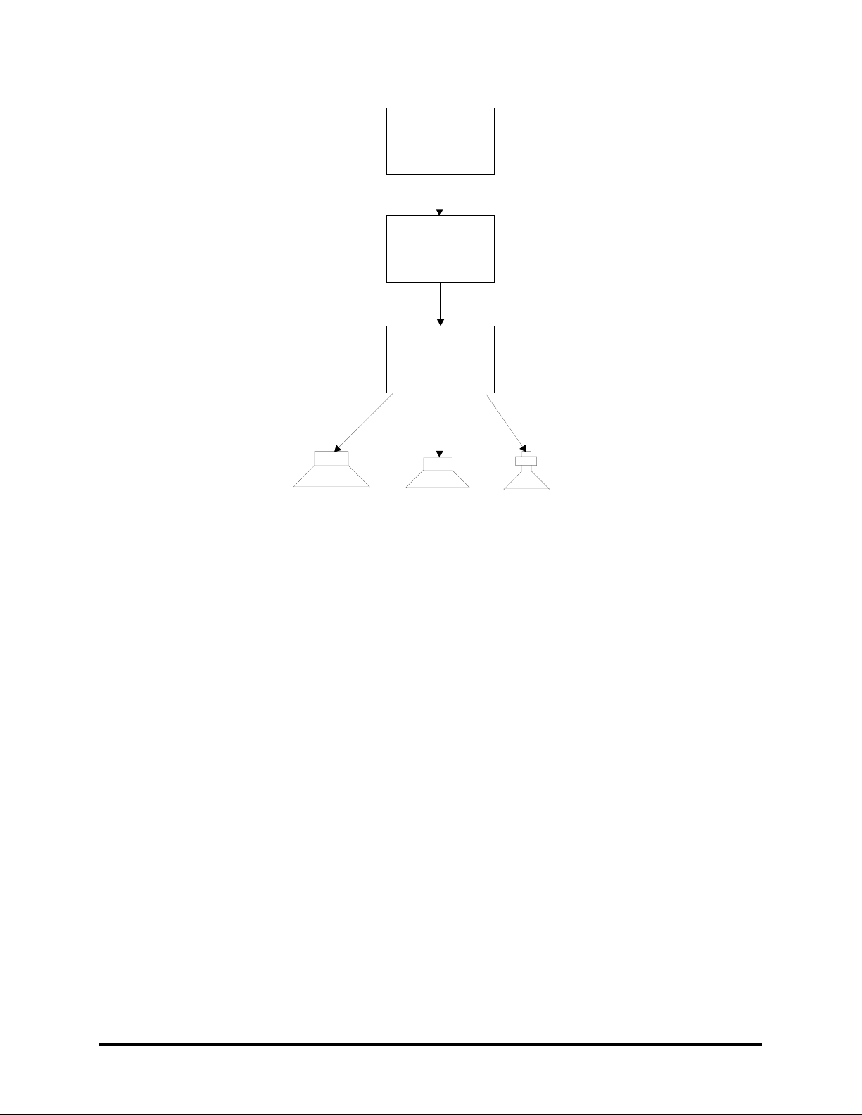
Signal
Source
Power
Amplifier
Passive
Crossover
Low Transducer
Figure 1 - Typical Passive Crossover Configuration
Mid Transducer High Transducer
This kind of crossover is called a passive crossover because it does not use any power other than
the power contained in the signal to accomplish its task. Passive crossovers have certain
limitations that make them inappropriate for large systems, or systems requiring high fidelity at
high sound pressure levels. Some of these limitations are…
• Insertion Loss: Some power is lost in the crossover network which lowers the efficiency
of the system.
• Power Handling: Passive crossovers that can handle more than a few hundred watts
require very large, very costly components. This makes them impractical for high-power
systems.
• Fidelity: The nature of the way passive crossovers work makes it difficult to design them
with high fidelity in mind. The kinds of components used in passive crossovers tend to
color the sound in undesirable ways.
To get beyond these limitations, large systems, or medium sized systems that require high
fidelity incorporate active crossovers. TDM 24CX series crossovers are active crossovers. These
crossovers are not usually housed in the speaker cabinet. They are separate units that are usually
mounted in a rack with the power amplifiers. They are called active crossovers because they
require power in addition to their input signal to carry out their task. Active crossovers are
different from passive crossovers in many ways. Here are the key differences…
• Line Level Signals: Active crossovers work with the line level signal before it reaches
the power amplifier. This allows them to use smaller, better components and designs.
© 2003 TDM Audio, Inc. Electronic Crossover Owner’s Manual Page 5
• External Power: Passive crossovers are simply inserted between the amp and the
speaker components. Active crossovers must be plugged into an electrical outlet in order
to work.
• Higher Typical Rolloff Rates: Passive crossovers typically roll off at rates from 6 to 12
dB per octave. Most modern active crossovers have rates of at least 24 dB per octave
(more about rolloff rates later).
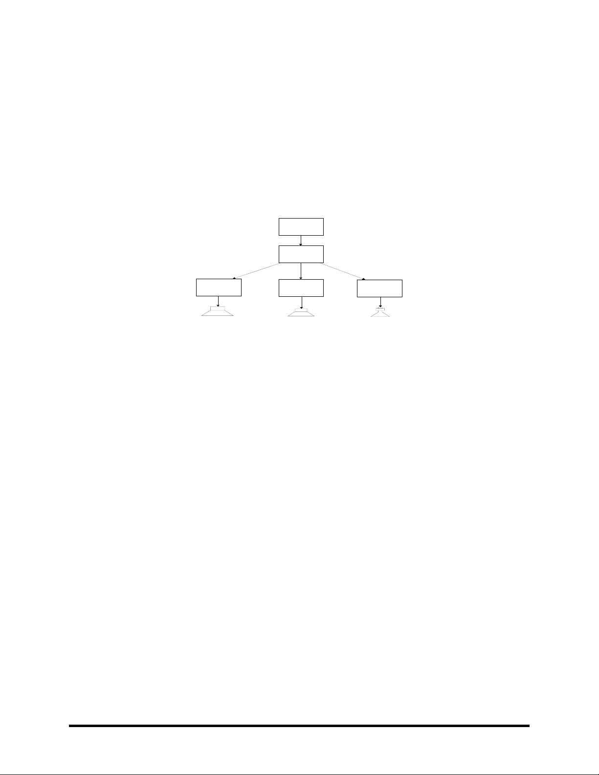
• More Power Amplifiers: Active crossovers break the signal into many different bands
before the power amplifiers. That means that you need one power amp channel per band.
Figure 2 shows a typical active crossover configuration.
Signal
Source
Active
Crossover
Lows Amp
Low Transducer
Figure 2 - Active Crossover Configuration
Mids Amp
Mid Transducer
Highs Amp
High Transducer
Crossover Terminology
• Crossover Frequency: This adjustment is often called the crossover point. It is the
frequency where the sound crosses over from one speaker to another. For example, if
your low-to-mid crossover frequency is 125 Hz, then frequencies below 125 Hz are
reproduced by the low speaker and frequencies above 125 Hz are reproduced by the mid
speaker. 125 Hz itself would be reproduced equally by both the low and the mid speakers.
• Rolloff Rate: A crossover’s rolloff rate determines how sharp the transition between one
set of speakers and another will be. Higher rolloff rates result in faster transitions. To
better understand this concept, let’s take an example.
Suppose you have a crossover stage dividing your mid frequencies and your high
frequencies. The crossover frequency of this stage is 2500 Hz. Sounds at 2500 Hz will be
equally reproduced by both the mid and high frequency speakers. As you go higher in
frequency, more of the sound is reproduced by the high speaker and less by the mid
speaker. As you go lower in frequency more of the sound is reproduced by the mid
speaker and less by the high speaker. If this crossover has a high rolloff rate (24 dB per
octave), at 1250 Hz, the difference between how much sound is reproduced by the mid
speaker and how much is reproduced by the high speaker will be 30 dB. In other words,
at 1250 Hz, 30 dB more of the signal is reproduced by the mid speaker than the high
speaker. At 625 Hz, the difference would be 54 dB. With a low rolloff rate (12 dB per
octave), the difference at 1250 Hz would only be 18 dB, and at 625 Hz it would be 30 dB.
Higher rolloff rates are generally considered good because they help protect speaker
components from damage at frequencies that are too low for them to handle. They also
© 2003 TDM Audio, Inc. Electronic Crossover Owner’s Manual Page 6
result in a greater overall efficiency of the system by making sure a band of frequencies
is always reproduced by the speaker components that are most efficient at reproducing it.
How Crossovers Work
To divide a range of frequencies into two or more smaller ranges, a crossover uses filter circuits.
A filter is simply a circuit that lowers the levels of unwanted frequencies in a signal. There are
two different kinds of filters used in crossovers:
• High Pass Filters: These reduce the levels of low frequencies in the signal.
• Low Pass Filters: These reduce the levels of high frequencies in the signal.
Filters roll off unwanted frequencies. Imagine that you have a high pass filter with a cutoff
frequency of 1000 Hz. That means the filter is supposed to keep frequencies above 1000 Hz
while discarding frequencies below 1000 Hz. Do you suppose, then, that a signal fed into this
filter at 999 Hz would simply not show up at the output? If you answered “No” you were
correct! In fact, a signal at 999 Hz would be virtually as loud at the output of this filter as a
signal at 1000 Hz. Signals that are above or near the cutoff frequency of a high-pass filter are
reproduced at normal levels. As the frequency gets lower, the level gradually decreases. The rate
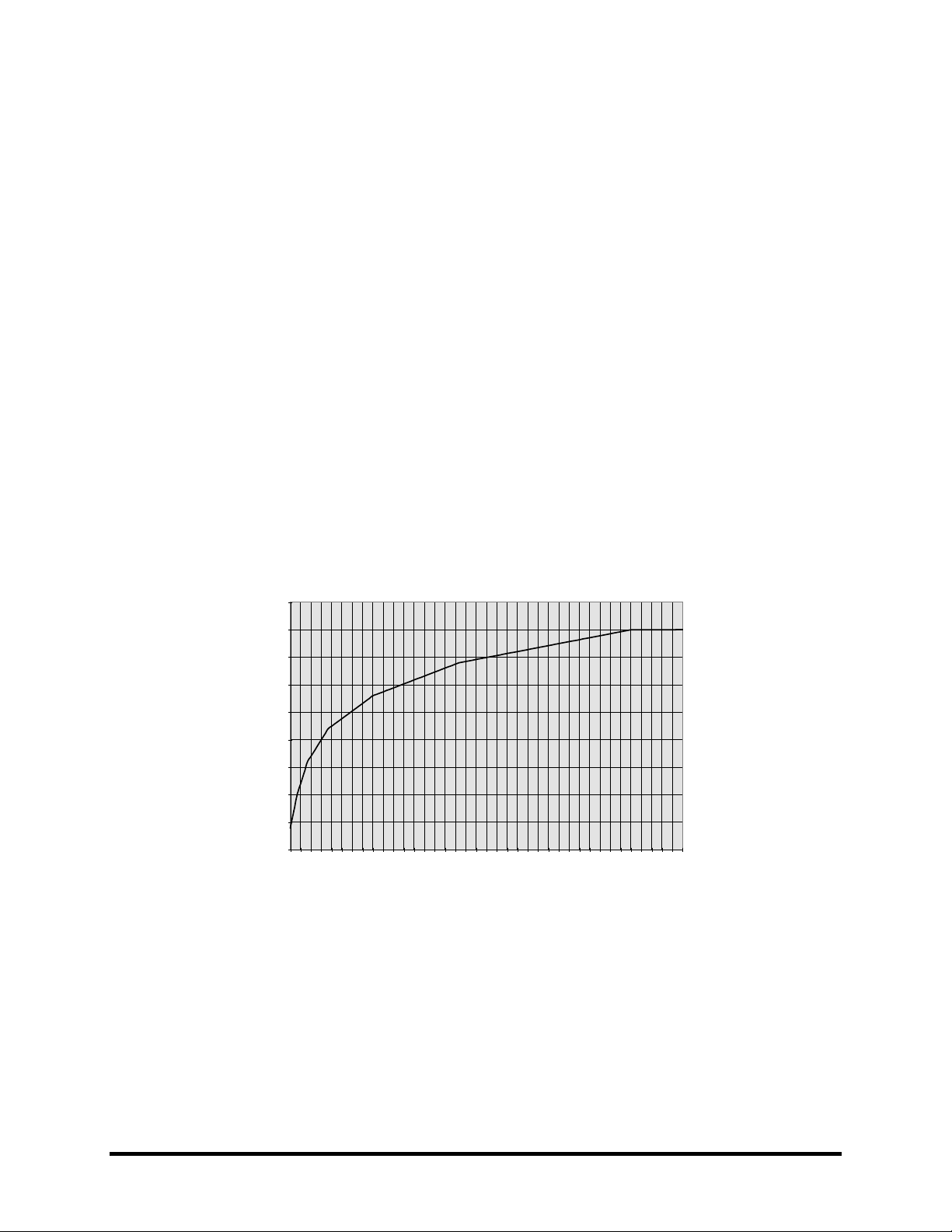
of decrease is called the filter’s rolloff rate. This term comes from the fact that on a graph of a
high-pass filter’s frequency vs. its gain, there is a smooth curve below the cutoff frequency. Here
is an example of such a graph:
5
0
-5
-10
-15
Gain (dB)
-20
-25
-30
-35
-40
20
140
260
380
500
620
740
860
980
1100
1220
1340
1460
1580
1700
1820
1940
2060
2180
Frequency (Hz)
2300
Figure 3 - Filter Frequency Response Curve
Figure 3 shows the curve of a 1000 Hz high-pass filter with a rolloff rate of 6 dB per octave. For
every for every octave below the cutoff frequency, we subtract 6 dB from the gain of the filter.
The cutoff frequency itself is actually at -6 dB. Filters with higher rolloff rates have steeper
looking curves. The TDM 24CX series crossovers have a 24 dB per octave rolloff rate. Figure 4
is what the above filter would look like with this higher rate.
© 2003 TDM Audio, Inc. Electronic Crossover Owner’s Manual Page 7
 Loading...