


COMMANDER 950
TOTAL ENGINE MANAGEMENT SYSTEM
ELECTRONICS AND FUEL INJECTION
MANUAL
199R-10149-5
NOTE: These instructions must be read and fully understood before beginning installation. If this manual is not fully understood, installation should not be attempted. Failure to follow these instructions may result in subsequent system failure.
Copyright © 2001 by Holley Performance Products, Inc.
Any unauthorized reproduction of this manual without the express written permission of Holley Performance Products, Inc. is strictly prohibited.
INTRODUCTION ................................................................................................................................................... |
4 |
||
1.0 TERMS & DEFINITIONS OF FUEL INJECTION MANAGEMENT SYSTEMS.............................................. |
5 |
||
1.1 |
FUEL MANAGEMENT SYSTEM ........................................................................................................................... |
5 |
|
1.2 |
THROTTLE BODY INJECTION (TBI).................................................................................................................... |
5 |
|
1.3 |
MULTI-POINT FUEL INJECTION (MPFI).............................................................................................................. |
6 |
|
1.4 |
ELECTRONIC CONTROL UNIT (ECU) ................................................................................................................. |
6 |
|
1.5 |
THROTTLE BODY ASSEMBLY (TBA) .................................................................................................................. |
6 |
|
1.6 |
FUEL INJECTORS ............................................................................................................................................ |
7 |
|
1.6.1 |
Bottom-Fed Fuel Injector ........................................................................................................................ |
7 |
|
1.6.2 |
Top-Fed Fuel Injector ............................................................................................................................. |
7 |
|
1.6.3 |
High-Impedance Injectors....................................................................................................................... |
8 |
|
1.6.4 |
Low-Impedance Injectors........................................................................................................................ |
8 |
|
1.7 |
MANIFOLD ABSOLUTE PRESSURE SENSOR (MAP) ............................................................................................. |
8 |
|
1.8 |
THROTTLE POSITION SENSOR (TPS)................................................................................................................ |
8 |
|
1.9 |
IDLE AIR CONTROL VALVE (IAC) ...................................................................................................................... |
9 |
|
1.10 MANIFOLD AIR TEMPERATURE SENSOR........................................................................................................... |
9 |
||
1.11 COOLANT TEMPERATURE SENSOR ................................................................................................................. |
9 |
||
1.12 OXYGEN SENSOR ......................................................................................................................................... |
9 |
||
1.13 ELECTRIC IN-LINE FUEL PUMP...................................................................................................................... |
10 |
||
1.14 ELECTRIC IN-TANK FUEL PUMP .................................................................................................................... |
10 |
||
1.15 FUEL PUMP INLET FILTER ............................................................................................................................ |
10 |
||
1.16 MAIN FUEL FILTER ...................................................................................................................................... |
11 |
||
1.17 FUEL PRESSURE REGULATOR ...................................................................................................................... |
11 |
||
1.18 FUEL RAILS................................................................................................................................................ |
11 |
||
1.19 FUEL INJECTION CONTROL METHODS ........................................................................................................... |
11 |
||
1.19A Speed Density EFI Systems................................................................................................................ |
11 |
||
1.19B Alpha-N EFI Systems.......................................................................................................................... |
11 |
||
1.20 CLOSED LOOP............................................................................................................................................ |
11 |
||
1.21 OPEN LOOP ............................................................................................................................................... |
12 |
||
2.0 HOW DOES FUEL INJECTION WORK? ....................................................................................................... |
12 |
||
2.1 |
SPEED DENSITY ........................................................................................................................................... |
14 |
|
2.2 |
ALPHA-N ..................................................................................................................................................... |
15 |
|
3.0 SKILL LEVEL REQUIRED............................................................................................................................. |
16 |
||
4.0 TOOLS REQUIRED FOR INSTALLATION.................................................................................................... |
16 |
||
5.0 ELECTRICAL CONNECTIONS ..................................................................................................................... |
16 |
||
5.1 |
STEP-BY-STEP WIRING HARNESS INSTALLATION.............................................................................................. |
17 |
|
5.2 |
NON-TERMINATED WIRE CONNECTION ........................................................................................................... |
17 |
|
5.3 |
PLUG-IN CONNECTIONS ................................................................................................................................ |
18 |
|
5.4 |
IGNITION WIRING.......................................................................................................................................... |
18 |
|
6.0 SOFTWARE INSTALLATION, SOFTWARE OPERATIONAL DESCRIPTION, AND COMPUTER |
|
||
OPERATION ....................................................................................................................................................... |
19 |
||
6.1 |
SOFTWARE INSTALLATION ............................................................................................................................. |
19 |
|
6.1.1 Windows 95, 98, NT............................................................................................................................. |
19 |
||
6.1.2 |
Windows 3.1 ........................................................................................................................................ |
19 |
|
6.2 |
BASIC COMPUTER OPERATION....................................................................................................................... |
19 |
|
6.3 |
SOFTWARE OPERATION AND NAVIGATION ....................................................................................................... |
20 |
|
6.4 |
BASE MAPS ................................................................................................................................................. |
21 |
|
6.5 |
ADVANCED AND BEGINNING USERS ................................................................................................................ |
21 |
|
7.0 STEP-BY-STEP INITIAL STARTUP INSTRUCTIONS .................................................................................. |
21 |
||
8.0 STEP-BY-STEP BASIC TUNING................................................................................................................... |
26 |
||
8.1 |
STARTUP / ENGINE WON’T START.................................................................................................................. |
26 |
|
2
9.0 REQUIRED ADDITIONAL EFI TUNING......................................................................................................... |
36 |
10.0 ALPHA-N TUNING....................................................................................................................................... |
50 |
11.0 DATA LOGGER........................................................................................................................................... |
53 |
APPENDIX 1 COMPLETE SOFTWARE OVERVIEW .......................................................................................... |
56 |
HARDWARE SETTINGS (HDWR SETTINGS).............................................................................................................. |
63 |
IDLE AIR CONTROL .............................................................................................................................................. |
65 |
PID Definitions (for Idle Air Control)................................................................................................................ |
65 |
O2 ..................................................................................................................................................................... |
66 |
APPENDIX 2 APPLICATION SPECIFIC TUNING ............................................................................................... |
67 |
SPECIFIC INFORMATION FOR RACE APPLICATIONS .................................................................................................. |
67 |
TBI SPECIFIC TUNING INFORMATION ..................................................................................................................... |
68 |
5.0L FORD SPECIFIC TUNING INFORMATION ........................................................................................................... |
69 |
APPENDIX 3 TUNING TROUBLESHOOTING .................................................................................................... |
70 |
APPENDIX 4 GENERAL TROUBLESHOOTING................................................................................................. |
73 |
APPENDIX 5 TESTING AND TROUBLESHOOTING ELECTRICAL COMPONENTS........................................ |
74 |
TESTING RELAYS................................................................................................................................................. |
74 |
TESTING THE MANIFOLD ABSOLUTE PRESSURE (MAP) SENSOR (1 BAR) .................................................................. |
74 |
TESTING THROTTLE POSITION SENSOR (TPS) ....................................................................................................... |
74 |
TESTING IDLE AIR CONTROL (IAC) MOTOR ............................................................................................................ |
75 |
TESTING COOLANT TEMPERATURE SENSOR ........................................................................................................... |
75 |
TESTING AIR CHARGE TEMPERATURE SENSOR....................................................................................................... |
75 |
TESTING THE OXYGEN SENSOR ............................................................................................................................ |
75 |
APPENDIX 6 OXYGEN SENSOR EFFECT ON PERFORMANCE...................................................................... |
76 |
APPENDIX 7 DESCRIPTION OF FUEL INJECTION SYSTEMS ........................................................................ |
77 |
COMBUSTION PRINCIPLES AND AIR / FUEL RATIOS .................................................................................................. |
77 |
EMISSIONS AND PERFORMANCE ............................................................................................................................ |
79 |
ENGINE MANAGEMENT SYSTEMS........................................................................................................................... |
79 |
Air Management............................................................................................................................................. |
79 |
Fuel Management .......................................................................................................................................... |
80 |
Ignition Timing Management .......................................................................................................................... |
81 |
APPENDIX 8 THE ENGINE APPLICATION AND THE SELECTION OF YOUR FUEL MANAGEMENT SYSTEM |
|
COMPONENTS. .................................................................................................................................................. |
81 |
INJECTOR FUEL FLOW ......................................................................................................................................... |
81 |
FUEL PRESSURE.................................................................................................................................................. |
82 |
BIGGER IS BETTER (TRUE OR FALSE) ................................................................................................................. |
82 |
APPENDIX 9 FUEL PUMPS ............................................................................................................................... |
83 |
APPENDIX 10 WIRING DIAGRAMS................................................................................................................... |
84 |
HOLLEY PERFORMANCE PRODUCTS LIMITED WARRANTY ......................................................................................... |
98 |
3

INTRODUCTION
Thank you for your purchase of the Holley Commander 950 Fuel Injection System. This tuning manual is designed to take all of the guesswork out of tuning your Commander 950. Holley is dedicated to providing products for our customers that not only outperform your expectations, but also are easy to install and tune.
NOTE: We highly recommend that you carefully read through all the manuals included with your system before
installing and tuning your Commander 950 Fuel Injection System. This will eliminate many problem areas and wasted time. This manual covers only the wiring and tuning aspects of the Commander 950. The hardware
installation manual (if included) will cover all aspects of the actual installation of the mechanical components (manifold, throttle bodies, etc.).
The Commander 950 systems are the most powerful fuel injection systems available today and are constructed from the highest quality components that have guided many racers to the winner's circle.Holley’s race-winning heritage and technology is taken to the next step with our Commander 950 fuel injection systems. These systems are perfect for both street and full-blown race applications, yet are user friendly.
This controller will allow you to tune fuel delivery, spark timing, boost compensation, fuel pump control, cooling fan, idle quality, and much more. As sophisticated as this system is, this tuning manual will walk you through each step, giving you maximum power, driveability, and reliability out of your engine.
Chapter 1 of this manual consists of the terms and definitions of fuel injection management systems. This is a glossary of components that you will encounter during the installation and tuning of your Commander 950 fuel injection system.
Chapter 2 of this manual will focus on the fundamentals and theory behind electronic fuel injection (EFI). This is where you will learn about how and why fuel injection works.
Chapter 3 will focus on the skills required to install your Commander 950 system. This includes items such as: basic computer knowledge, limitations of the system, and general automotive knowledge.
Chapter 4 will focus on the tools required to install your Commander 950 system
Chapter 5 gives comprehensive instruction on the wiring installation of your Commander 950 system. This is a very comprehensive section and includes step-by-step instructions that are easy to follow in very simple terms.
Chapter 6 covers the software installation, software operational description, computer operation, and fuel map downloading.
Chapter 7 provides step-by-step instruction to get you through initial fire up.
Chapter 8 goes through the basic tuning of your Commander 950. This will include detailed instructions on tuning Speed Density systems.
Chapter 9 will cover the fine points of tuning required to realize optimal performance in Speed Density systems. This advanced tuning section will allow you to squeeze every last bit of power and driveability out of your vehicle.
Chapter 10 covers some basic fundamentals for Alpha N systems.
Chapter 11 covers the Datalogger functions.
Appendix 1 covers complete software overview, including: hardware settings, idle air control, PID definitions, and O2.
Appendix 2 covers application specific tuning. It will include sections on Race Application, TBI applications, and 5.0L Ford applications.
Appendix 3 covers tuning troubleshooting.
Appendix 4 is our general troubleshooting guide. This section will answer many of the most common stumbling areas in fuel injection tuning. If you are having a problem, start by looking through this section first.
Appendix 5 covers the testing and troubleshooting of electrical components, including the testing of : Relays, MAP Sensor, TPS, IAC, Coolant Temperature Sensor, Air Charge Temperature Sensor, and Oxygen Sensor.
Appendix 6 covers the Oxygen sensor effect on performance.
4
Appendix 7 covers the description of fuel injection systems, including: combustion principles and air/fuel ratios, emissions and performance, and engine management systems. These engine management systems consist of: air management, fuel management, and ignition timing management.
Appendix 8 covers the engine application and the selection of your fuel management system components, including: injector fuel flow and fuel pressure.
Appendix 9 covers the two kinds of fuel pumps and their flow characteristics.
Appendix 10 shows the many wiring diagrams needed to install your Commander 950 fuel injection system.
1.0 TERMS & DEFINITIONS OF FUEL INJECTION MANAGEMENT SYSTEMS
1.1 Fuel Management System
Fuel management systems comprise a selection of components and assemblies whose main function is to supply a mixture of fuel and air to the engine in proportions such that it will be easily ignited by the spark. In a carbureted system the main components are the carburetor and the mechanical fuel pump. In fuel injection systems the main components are the fuel injectors, the air valve, the electric fuel pump, and the Engine Control Unit (ECU). The fuel pump’s main function is to supply fuel to the metering unit: carburetor or fuel injectors. Airflow is adjusted by the air valve. In carburetors the air valve is part of the carburetor. In fuel injection systems the air valve is part of the metering system, such in the case of the Throttle Body Injection systems (TBI systems), or is separate from the fuel metering system as in the Multi-Point Fuel Injection (MPFI systems). In fuel injection systems, the ECU is the computer that controls the fuel metering function of the fuel injectors according to the input of the sensors. In the carburetor the jets and the vacuum regulated by the air valve control the fuel metering function.
Throttle Body Injection (TBI) |
Multi-Port Fuel Injection (MPFI) |
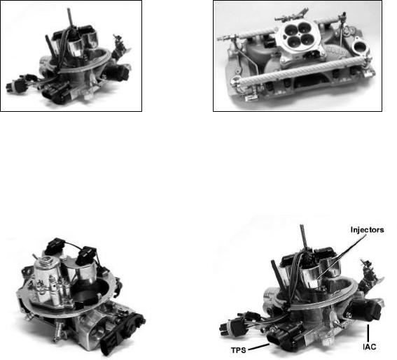
1.2 Throttle Body Injection (TBI)
In TBI systems, the throttle body assembly has two major functions: regulate the airflow and house the fuel injectors and the fuel pressure regulator. The choices of throttle bodies range from single barrel/single injector unit generally sized for less than 150 HP to four barrel/four injector unit capable of supporting fuel and air flow for 600 HP The injectors are located in an injector pod above the throttle valves. The quantity of fuel the injector spray into the intake manifold is continuously controlled by the ECU. Most of the TBI systems use bottom fed fuel injectors. The injector spray pattern is designed to allow fuel to pass between the throttle valve and the throttle bore.
5
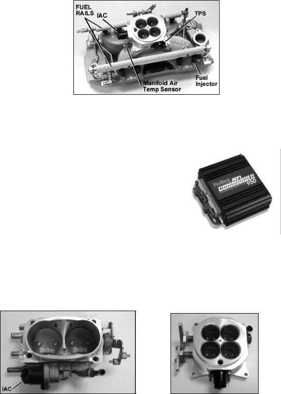
1.3 Multi-Point Fuel Injection (MPFI)
A multi point fuel injection systems meters the fuel to each cylinder individually via the fuel injector located just upstream of the intake valve. The fuel is supplied to the injectors via a fuel pump. The MPFI is superior to the TBI systems because it will generate better fuel economy, higher power output and improved throttle response. These advantages are mainly due to the proximity of the injector to the intake valve and better fuel atomization. Most of the MPFI systems use one injector per cylinder but in certain applications up to two injectors per cylinder are used to supply the required fuel for the engine.
MPFI system
1.4 Electronic Control Unit (ECU)
The function of the ECU is to "tweak" or "fine tune" the engine operation to obtain the most complete and efficient combustion process. The ECU microprocessor receives input signals from various sensors from the engine and generates specific outputs to maintain optimum engine performance. The engine operating modes controlled by the ECU typically include the following:
§Baseline Fueling
§Spark Ignition Timing
§Cold and hot start
§Acceleration enrichment
§Battery voltage compensation
§Deceleration cut/off or enleanment
§ Run mode (open loop or closed loop) |
ECU |
1.5 Throttle Body Assembly (TBA)
The throttle body assembly (also called air valve) controls the airflow to the engine through one, two, or four butterfly valves and provides valve position feedback via the throttle position sensor. Rotating the throttle lever to open or close the passage into the intake manifold controls the airflow to the engine. The accelerator pedal controls the throttle lever position. Other functions of the throttle body are idle bypass air control via the idle air control valve, coolant heat for avoiding icing conditions, vacuum signals for the ancillaries and the sensors.
2 Barrel Throttle Body |
4 Barrel Progressive Throttle Body |
6
1.6 Fuel Injectors
There are basically two approaches in delivering the fuel to the engine:
•Above the throttle plate as in throttle body injection
•In the intake port toward the intake valves as in multi-point injection
The fuel injector is continuously supplied with pressurized fuel from the electric fuel pump. The pressure to the injector is maintained constant by the fuel pressure regulator. The fuel injector is an electric solenoid valve that when driven by the ECU delivers a metered quantity of fuel into the intake manifold. The ECU controls the fuel flow by opening and closing the injector. The time the injector is open is defined as pulse width. The time the injector is driven into an open condition is determined by the following sensor inputs:
• Engine RPM |
• Oxygen sensor feedback voltage |
• Throttle position (TPS) |
• Intake air charge temperature |
• Manifold absolute pressure or mass air flow |
• Battery voltage |
• Engine coolant temperature |
|
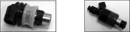
1.6.1 Bottom-Fed Fuel Injector
NOTE: This is typically used in TBI systems.
This electromagnetic valve meters fuel into the intake manifold proportional to the air being induced into the engine. When the valve is energized, the electromagnetic force generated by the solenoid lifts the pintle/ball from the seat. Fuel under pressure is then injected into the throttle body bore. For throttle body injection, a hollow conical spray is required to aim the metered flow around the throttle valve.
Bottom-Fed Fuel Injector |
Top-Fed Fuel Injector |
1.6.2 Top-Fed Fuel Injector
NOTE: This is typically used in MPFI systems.
When the ECU activates this electromagnetic valve, the injector meters and atomizes fuel in front of the intake valve. The fuel enters the top and is discharged via the metering orifice at the bottom at high pressure. The spray geometry and cross sectional area is specific to the engine application. For MPFI system, a solid spray geometry is required to avoid fuel wall wetting.
In general there are three injector metering design configuration:
§1 Pintle injector. This is one of the first fuel injector designs applied to automotive fuel engine management
technology. The fuel flow is metered via an annular orifice between the pintle and the seat. The tip of the pintle has the function of generating the required spray geometry. Pintle type injectors are very susceptible to carbon deposit and have slowly been replaced by director plate metering technology. A conical seat between the plunger and the seat achieves the seal of these injectors.
§2 Disk injector. The disc injector design is different from the types of injectors discussed above because a disc
replaces the plunger. Sealing is achieved by seating the disc against the protrusion of the metering orifice. The main advantage of the disc is the lower mass and it is perceived that it can reciprocate at higher frequencies than a plunger. Recent advances in solenoid and plunger manufacturing technology have significantly reduced the weight disparity between the disc and plunger designs. These injectors make use of the director disc design to achieve the required flow and spray geometry
7
§3 Ball-on-a-stick injector. This metering design is mostly used in the director plate application. The seal is
achieved between a conical seat and a spherical plunger. The director plate has the function of metering the fuel and generating the required spray geometry. Fuel flow is adjusted by the size of the hole machined into the director plate and the spray geometry is adjusted by the orientation of the holes in the director plate. Because the metering components are not exposed to the intake manifold environment, the injector is less susceptible to carbon deposits. All Holley injectors are ball-on-a-stick style.
According to the solenoid design and metering requirements the injectors are further defined into two main categories:
1. High-impedance injectors 2. Low-impedance injectors
1.6.3 High-Impedance Injectors
Depending of the brand of the injector, the electric resistance of the coil is in the range 12 to 16 Ohms. In general the highimpedance injector are rated for static fuel flows of 12 to 50 lb./hr. The high-impedance injectors are used with ECUs that are designed with saturation injector drivers. The advantage of using saturation drivers is that the currents running through the ECU circuits and the injectors are relatively low, thus generating less heat. The disadvantage of saturation drivers is that the driver has a slower response time, which could affect the full utilization of such a system at very high engine RPM (two stroke engine applications and four stroke engine applications of 10000RPM and above).
1.6.4 Low-Impedance Injectors
Depending of the brand of the injector, the electric resistance of the coil is in the range 1.2 to 4.0 Ohms. In general the highimpedance injector are rated for static fuel flows of 55 to 160 lb./hr. The low impedance injectors are designed to be run with an ECU that employs peak and hold injector drivers (also called current sensing or current limiting drivers). The advantage of these drivers is that they limit the current in the injector and therefore reduce the heat generation in the ECU. In general, most bottom-fed injectors are of the low impedance design.
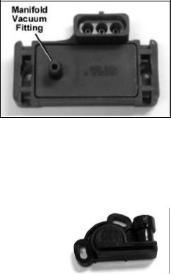
1.7 Manifold Absolute Pressure Sensor (MAP)
The map sensor represents the intake manifold vacuum gage for the ECU. The sensor is a three-wire sensor located on or attached to the intake manifold. The function of this sensor is to measure the changes in the intake manifold air pressure and generates an electric signal that is proportional to the change of pressure. There are basically three types of Map sensors: 1bar, 2bar and 3 bar. The 1bar map sensor is for naturally aspirated engine applications. The 2 and 3bar sensors are for forced induction engine applications (turbocharged or supercharged). The 2 bar sensor is for applications up to 15 psi forced induction pressure and the 3 bar sensor is for applications up to 30 psi forced induction pressure. This signal is fed into the ECU and is used to:
• Adjust the fuel delivery
MAP sensor
• Spark ignition calculations
NOTE: Map sensors read vacuum as kPa (Kilo-Pascals: metric units for pressure). Please see the Map Value to Manifold Pressure Value chart on page 74 in Appendix 5.
1.8 Throttle Position Sensor (TPS)
The TPS is a three-wire sensor that is mounted on the throttle body assembly and is actuated by the throttle shaft. The TPS is basically a variable resistor (potentiometer) that sends a voltage signal to the ECU that is proportional to the throttle shaft rotation. When the throttle shaft is open the sensor emits a high voltage signal and when the throttle shaft is closed it emits a low voltage signal. The voltage signal from the TPS changes between approximately 0.45 V at idle to 5.OV at wide-open throttle.
Throttle Position Sensor
8
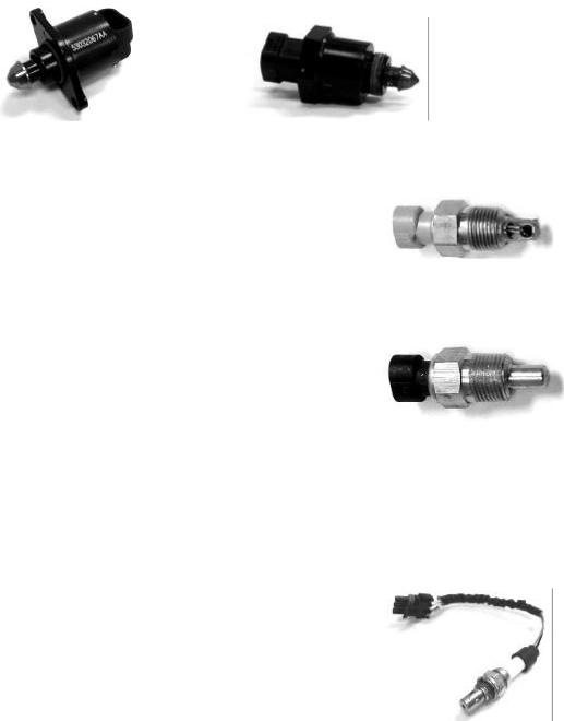
1.9 Idle Air Control Valve (IAC)
The IAC is located in the throttle body of the TBI and MPFI. The valve consists of a stepper motor that adjusts the position of its pintle to vary the bypass air during idle and of idle conditions. During the closed throttle condition (idle), the ECU constantly compares actual engine speed with the programmed desired engine speeds. Discrepancy between these two values result in activation of the stepper motor increasing or decreasing the bypass air around the throttle plates until desired engine speed is achieved. This operation is similar to a controlled vacuum leak. The following input signals or conditions determine the position of the valve:
•Throttle position sensor
•Engine load (MAP, A/C compressor, power steering, gear selection)
•Engine coolant temperature
Bolt-In IAC |
Screw-In IAC |
1.10 Manifold Air Temperature Sensor
The air charge sensor is located in the engine air intake to sense the air induced into the engine manifold. The sensor consists of a thermistor, which generates a voltage signal, that is proportional to the air temperature. This voltage signal is used by the ECU to calculate the air density and using these results to adjust the fueling levels for a particular engine load. A function of the air temperature signal is to:
Manifold Air Temperature Sensor
• Adjust fueling during cold start based on air temperature
1.11 Coolant Temperature Sensor
The coolant temperature sensor is a two-wire sensor that is threaded into the engine block |
|
and is in direct contact with the coolant. The function of this sensor is to generate a signal |
|
that the ECU uses to adjust the fueling levels required for the operation of the engine and |
|
operate ancillaries. The thermistor contained in the sensor generates an electric signal |
|
that is proportional to the coolant temperature. Other functions of the coolant temperature |
|
signal are: |
Coolant Temperature Sensor |
• Idle speed adjustment via the IAC |
|
• Modify spark advance |
|
• Electric cooling fan operation |
|
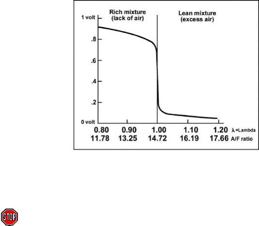
1.12 Oxygen Sensor |
|
The oxygen sensor (also known as a Lambda sensor) is located in the exhaust manifold and its function is to measure the oxygen content in the exhaust gases. The sensor is an electrochemical cell, which develops a voltage signal between its two electrodes that is proportional to the oxygen content in the exhaust gases. The oxygen sensor adjusts and maintains an optimum air fuel mixture to control the exhaust emission and the fuel economy. When the oxygen content in the exhaust is high due to a lean mixture, the output voltage of the sensor is close to zero. If the fuel air mixture is on the rich side, the oxygen content in the exhaust is low and the output voltage of the sensor approaches 1.0 volts. Holley uses a 3-wire (heated) O2 sensor.
Three-Wire Heated Oxygen Sensor
9
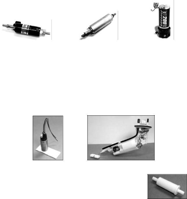
1.13 Electric In-line Fuel Pump
The function of the electric fuel pump is to deliver pressurized fuel to the fuel injection system. The ECU activates the fuel pump relay to operate the fuel pump when the ignition switch is in the On or start position. The pumps are designed to match certain flow and pressure specification for the engine application. In TBI applications, the fuel pump must supply enough fuel flow for the engine Wide-Open Throttle (WOT) output at 15 to 20 psi. In multi-port applications, the fuel pump must be able to supply enough fuel at full engine load to maintain at least 43.5 psi at the fuel rail. At idle, the fuel pressure regulator must be able to return the excess fuel to the tank and maintain the required system pressure. Most of the cars prior to 1987 use an in-line external electric fuel pump.
In-line Fuel Pump |
High-Flow In-line Fuel Pump |
High Performance Race Pump |
1.14 Electric In-tank Fuel Pump
Almost all car applications after 1987 designed their fuel pump assembly inside the fuel tank. The advantage of having the fuel pump in the fuel tank is mainly lower noise, lower potential leakage problems, and less mounting sensitivity of the pump with respect to lift of fuel from the tank. The in-tank pump went through several designs evolving from a simple "pump on a stick" to a complex in-tank, fuel-sending module. The new designs combine the high-pressure electric fuel pump, noise isolation, and a fuel level sensor into one compact modular package. This new design also helps in reducing hydrocarbon emissions. The hot gasoline returning from the fuel system is returned to the reservoir surrounding the fuel pump. By returning the hot fuel to the reservoir heating of the bulk fuel in the fuel tank is avoided, thus reducing the evaporation of the high volatile portions in the fuel. At present, all fuel tank modules are designed and serviced as a complete unit. If the pump or fuel level sensor fails, the entire unit will have to be changed.
NOTE: Never use an in-tank, low-pressure fuel pump in conjunction with an external high-pressure fuel pump. The lowpressure, in-tank fuel pump will become a restriction to the external, high-pressure fuel pump. This condition will result in fuel starvation and engine damage.
Aftermarket In-tank Pump |
Stock-style pump module |
1.15 Fuel Pump Inlet Filter
The function of this filter is to eliminate any impurities that might harm the fuel pump. In the in-line fuel pump type, this filter is external to the fuel tank and is in a replaceable cartridge filter. In the in-tank fuel pumps, the fuel filter is in the form of a sock and is directly attached to the pump in the "pump on a stick" version and attached to the fuel pump module in the module version. These filters have a rating of 120-150 microns.
Fuel Pump Inlet Filter
NOTE: This fuel filter is required to avoid fuel pump damage.
10
1.16 Main Fuel Filter
The function of this filter is to eliminate any contaminants after the fuel pump. These are either small enough to pass through the fuel filter of the pump inlet or are generated by the fuel pump. This fuel filter is also of the cartridge type, but is designed to sustain much higher fuel pressures than the fuel pump inlet filter. These filters have a rating of 10 microns.
NOTE: This fuel filter is required to avoid fuel injector damage.
Main Fuel Filter
1.17 Fuel Pressure Regulator
Fuel system pressure is maintained by the regulator, while excess fuel is returned to the fuel tank. The regulator consists of two chambers separated by a diaphragm assembly. On the fuel side of the diaphragm, a throttling valve is employed to increase or restrict fuel flow as the fuel pressure fluctuates. The other side contains a spring with an adjustment screw that is set at the factory for correct system pressure and flow. This chamber is connected to the intake manifold in MPFI systems to reference the vacuum in the manifold during engine operation. This pressure reference is required to maintain a constant differential pressure across the metering orifice of the fuel injector. On TBI systems, the regulator is in the throttle body assembly.
Fuel Pressure Regulator
1.18 Fuel Rails
The function of the fuel rails is to deliver fuel at system pressure to the fuel injectors and to retain the fuel injectors on the intake manifold. At the end of the rails, there is the pressure regulator that maintains a constant pressure at the fuel injector regardless of the fuel being injected. The location of the fuel regulator with respect to the fuel rail and the internal volume of the fuel rail is important in maintaining the fuel pressure stability in the system.
Fuel Rails
1.19 Fuel Injection Control Methods
1.19A Speed Density EFI Systems
Speed density EFI systems use input from the MAP sensor and engine rpm to determine the base amount of fuel to inject. The Commander 950 uses these inputs to look up a value from the base fuel table. This method is used on many OEM vehicles.
1.19B Alpha-N EFI Systems
Alpha-N EFI systems use input from the Throttle Position Sensor (TPS) and engine rpm to determine the base amount of fuel to inject. The Commander 950 uses these inputs to look up a value from the base fuel table. This method is used only for race cars that have very low manifold vacuum. This method does not sense changes in engine load well and is not recommended for street driven vehicles.
1.20 Closed Loop
Closed loop defines the engine operation where the fueling level is calculated and corrected by the ECU based on the voltage signal from the 02 sensor (lambda sensor). When the 02 sensor (lambda sensor) emits a voltage signal above 0.45V due to a rich mixture in the exhaust manifold, the ECU reduces the fueling level by reducing the pulse width of the injector. The 02 sensor voltage (lambda sensor voltage) is the feedback that modifies the fuel control program that is based on other signals.
11
O2 Sensor Voltage
1.21 Open Loop
Open loop defines the engine operation where the fueling level is calculated by the ECU with only the input signals from the throttle position sensor (TPS), from the coolant and/or air charge temperature, and from the manifold absolute pressure (MAP).
For additional information, see Appendix 7 (Description of Fuel Injection Systems)
2.0 How Does Fuel Injection Work?
A fuel injection system is made up of many specialized components that are designed to work together to properly meter fuel and air. A properly tuned EFI system will allow for the optimum air/fuel ratio during all operating conditions. The Commander 950 is easily adjustable to realize all of the benefits EFI will deliver.
The main components that make up a fuel injection system are a combination of mechanical and electrical devices. These typically include:
ØEFI Intake Manifold
ØThrottle Body (also called Air Valve)
ØFuel Injectors
ØHigh-Pressure Fuel Pump
ØFuel Pressure Regulator
ØEngine Coolant Temperature Sensor (ECT)
ØManifold Air Temperature Sensor
ØManifold Air Pressure Sensor (MAP Sensor)
ØOxygen Sensor (O2 Sensor)
ØThrottle Position Sensor (TPS)
ØIdle Air Control Motor (IAC)
ØRPM Signal Device (distributor or crank trigger)
ØComputer (Electronic Control Unit (ECU)
NOTE: If you are not familiar with ALL of these terms, please refer to the glossary in Chapter 1.
Let’s take a closer look at what makes fuel injection work.
The fuel injection cycle begins by air entering the engine through the throttle body. The ECU needs to then calculate how much fuel to add for the amount of air that is entering the engine. Although there are several methods to do this, the Commander 950 uses inputs from the MAP Sensor and engine speed to calculate an initial amount of fuel to inject. The MAP sensor indicates the load on the engine by sensing manifold vacuum.
12
The Air Temperature Sensor monitors the temperature of the incoming air. This tells the ECU what the outside temperature is and allows the ECU to adjust the fuel for this. The Coolant Temperature Sensor tells the ECU the temperature of the engine and will add extra fuel when the engine is colder, just like the choke on a carburetor. Using these inputs, the ECU can then calculate how much fuel to inject.
The fuel system is made up of several basic components. A high-pressure, high-volume fuel pump supplies fuel to the engine. Multi-port EFI fuel systems usually operate at a pressure between 43 to 65 psi compared to a carburetor fuel system (5 to 8 psi). TBI EFI systems usually operate between 12 and 22 psi. Since EFI fuel pumps are designed to push fuel, they do not have the ability to pull fuel for long distances. The pump needs to be mounted close to the tank and preferably below the fuel level in the tank
The fuel pump supplies fuel to the fuel rails, which supply fuel to the fuel injectors in multi-port EFI systems. Fuel that is not used by the fuel injectors passes to the fuel pressure regulator. The regulator bypasses fuel back to the fuel tank while maintaining the pressure it is adjusted to. Throttle Body Injection systems (TBI) are self-contained, meaning the injectors, fuel inlet and outlet, and regulator are contained in the TBI unit.
The following is a simple verbal and visual description of how fuel injection systems determine how much fuel to deliver. The terms and ideas used are explained in detail later in this manual
There are two methods that the Commander 950 uses to determine how much fuel to inject. These are Speed Density and Alpha-N. Almost all engines, except some race engines will use Speed Density.
The following describes the sequence of events that happens each time fuel is injected into an engine. This literally happens over 250 times a second.
13
2.1Speed Density
1.Engine speed (1000 RPM) and manifold pressure from the MAP sensor (38 kPa) are read by the ECU. From these values, it obtains a number from the base fuel map (32).
2.The ECU then looks at the reading from the Air Temperature Sensor and may modify the fuel value. In this case it adds
.8% more fuel.
3.The ECU looks at the reading from the Engine Coolant Temperature Sensor and may further modify the value. In this case it is at 100% (operating temperature) so it does not add or subtract more fuel.
4.The ECU will look and see if the engine is accelerating based on the Throttle Position Sensor. In this case the engine speed is not changing.
5.From these values, it will calculate the amount of fuel that the user has programmed to deliver which is called the pulsewidth. If the engine is closed loop, it will modify this value to maintain an air/fuel ratio of 14.7:1.
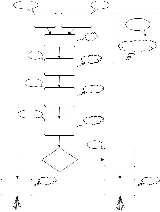
The following flowchart (Figure 1) illustrates this example:
1000 RPM |
38 kPa |
ENGINE |
MANIFOLD |
Key: |
|
PRESSURE |
|
||
SPEED |
Sensor Data |
||
(MAP Sensor) |
|||
|
|
Input |
|
|
|
32 |
|
BASE FUEL MAP |
|
||
|
VALUE |
ECU Calculations |
|
|
|
||
|
|
and Adjustments |
|
47°F |
|
|
|
|
|
100.8% |
|
MANIFOLD AIR |
|
||
TEMPERATURE |
|
||
|
MODIFIER |
|
|
(Air Temp Sensor) |
|
||
180°F
100.0%
COOLANT TEMPERATURE
MODIFIER
(Water Temp Sensor)
No Change
100.0%
ACCELERATION
ENRICHMENT
(change in TPS and
MAP Sensor)
|
|
0.82v |
|
|
|
|
|
CLOSED LOOP |
|
Open Loop |
CLOSED LOOP |
Closed Loop |
FEEDBACK TO |
|
MAINTAIN 14.7:1 |
||||
|
|
|||
|
OR |
|
AIR/FUEL RATIO |
|
|
OPEN LOOP? |
|
(Oxygen Sensor) |
|
|
3.8 ms |
|
3.1 ms |
|
AMOUNT OF FUEL |
|
|
AMOUNT OF FUEL |
|
INJECTED |
|
|
INJECTED |
|
(Pulse Width) |
|
|
(Pulse Width) |
Figure 1 Engine at Operating Temperature; Speed Density ECU Strategy Flowchart
14
2.2 Alpha-N
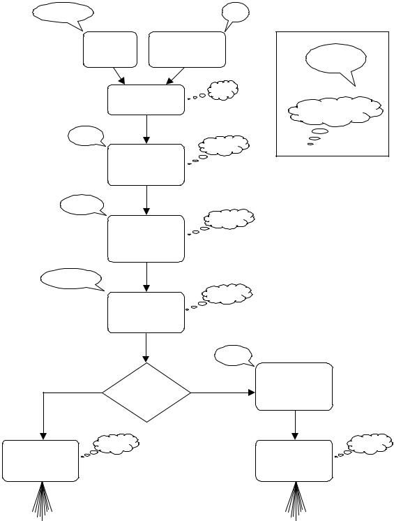
An Alpha-N system is similar to a speed density EFI system, except that for step 1, the ECU will look at engine speed and the position of the Throttle Position Sensor, instead of the MAP Sensor, to determine the value from the base fuel map. The following flowchart (Figure 2) illustrates this example.
1000 RPM |
40 |
THROTTLE |
Key: |
|||
ENGINE |
POSITION |
|
||
SPEED |
Sensor Data |
|||
|
(TPS) |
|||
|
|
Input |
||
|
|
|
||
BASE FUEL MAP |
|
32 |
||
|
|
|||
VALUE |
|
|
ECU Calculations |
|
|
|
|
||
|
|
|
and Adjustments |
|
47°F |
|
|
|
|
|
|
|
100.8% |
|
MANIFOLD AIR |
|
|
|
|
TEMPERATURE |
|
|
|
|
MODIFIER |
|
|
|
|
(Air Temp Sensor) |
|
|
||
180°F
100.0%
COOLANT TEMPERATURE
MODIFIER
(Water Temp Sensor)
No Change
100.0%
ACCELERATION
ENRICHMENT
(change in TPS and
MAP Sensor)
|
|
0.82v |
|
|
|
|
|
CLOSED LOOP |
|
Open Loop |
CLOSED LOOP |
Closed Loop |
FEEDBACK TO |
|
MAINTAIN 14.7:1 |
||||
|
|
|||
|
OR |
|
AIR/FUEL RATIO |
|
|
OPEN LOOP? |
|
(Oxygen Sensor) |
|
|
3.8 ms |
|
3.1 ms |
|
AMOUNT OF FUEL |
|
|
AMOUNT OF FUEL |
|
INJECTED |
|
|
INJECTED |
|
(Pulse Width) |
|
|
(Pulse Width) |
Figure 2 Engine at Operating Temperature – Alpha-N ECU Strategy Flowchart
15

3.0 SKILL LEVEL REQUIRED
Installation of the COMMANDER 950 intake system and the ECU requires approximately the same level of skill and experience to replace or service an induction system consisting of a carburetor and conventional intake manifold (as well as basic wiring skills for the installations of the ECU).
Tuning of the system requires basic computer skills and a basic knowledge of engine and fuel injection principles. The information needed to tune this system is included in this manual. Read it thoroughly.
Tuning your EFI system is an ongoing project, until you get it dialed in for all conditions. Be patient.
NOTICE: If you are not absolutely certain that you have the skills and experience required to perform these procedures, we strongly recommend you have this system installed and tested by a technician with specialized training in EFI and fuel systems service.
4.0 TOOLS REQUIRED FOR INSTALLATION
The following is a list of materials, which may be needed, depending on the application.
qLaptop PC with Windows 3.1, 95, 98, or NT and serial communications port (minimum graphics required=800 x 600)
qDigital Volt-Ohm meter
qScrewdriver set
qDrill and assorted bit sizes
qHole saw (2”) or Greenlee punch
qTiming/Advance Light (Dial back recommended)
qStandard wrench set
qStandard socket set
qFuel pressure gauge
qWire terminal pliers
qElectrical tape
qZip ties
q14 gauge wire
The following is a list of parts that may be required to complete this installation (dependent on the application).
q534-138 GM small cap HEI adapter (included with MPI kits)
q534-139 Ford TFI adapter (included with 5.0L Ford kits)
q538-13 Two bar MAP sensor
q538-23 Three bar MAP sensor
q840-110 Crank Trigger required for LT1 engines
q800-501 DIS system required for LS1 engines
q534-136 Knock Sensor wiring kit
q534-134 Cooling Fan Relay kit
q534-135 Crank Trigger wiring kit
5.0 ELECTRICAL CONNECTIONS
Proper installation of the wiring harness and all electrical connections are critical for proper and reliable operation of any EFI system. Damage to the ECU can also result from improper wiring.
Wiring diagrams are provided for reference during connection of electrical components. These diagrams shows the connectors included with the wiring harness and table shows the color codes and connections for all of the loose wires without connectors. See Appendix 10 for the wiring harness diagram.
NOTE: Some of the wiring schematics include wiring for optional kits. This is the cooling fan relay kit. Cooling relay kits can be purchased separately.
16
5.1 Step-by-Step Wiring Harness Installation
NOTE: It is advised to leave the battery completely disconnected until the installation of the entire system is completed.
1.ECU MOUNTING – The ECU should be mounted as far away from the ignition box as is feasible (minimum 6”). The ECU must be installed in the vehicle in a location free from moisture and dirt. The glove box area is usually a good location in most vehicles. There are sheet metal screws included for this purpose. The ECU must be grounded. If you mount it on a non-metallic surface (ex. fiberglass body), run a 14 gauge ground wire to the chassis.
2.WIRING HARNESS - The wiring harness will need to be fed through the firewall in the vehicle. Drill a 2 inch diameter hole and feed the harness through it. A grommet is provided for this hole so the harness will not be damaged. Be very careful that the hole you drill does not interfere with items like wiring harnesses, heating, or AC systems.
3.CONNECT WIRING HARNESS - After the harness is routed through the hole connect it to the ECU. Route the rest of the harness into the engine compartment.
4.INSTALL RELAY - A system power relay is included. The relay holder for it is about 3 feet from the ECU connection. The relay can be mounted inside the interior or in the engine compartment. Decide where you want it and secure the relay. A sheet metal screw is provided for this purpose. Be careful that you don’t drill through the firewall and damage something. Mount the relay and attach it to the harness.
5.INSTALL FUSE - The 15 amp fuse needs to be installed in the fuse holder. The fuse is included and the fuse holder is located near the ECU. Install it now.
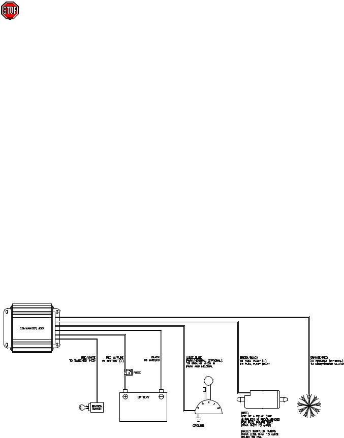
5.2 Non-Terminated Wire Connection
Next, the non-terminated wires will be connected (Figure 3). The following chart provides an overview. However, each one will be described separately.
NON-TERMINATED WIRE COLOR AND DESCRIPTION |
WIRE CONNECTION LOCATION |
Black |
Ground connection |
Red with fuse |
12 Volt - attach to the battery |
Red/White |
Switched +12 volt power |
Orange/Red |
AC Request (Optional) +12v |
Light Blue |
Park/Neutral (Optional) Ground |
Green/Black |
+ 12 volt Fuel Pump |
WARNING! Keep all wires away from hot exhaust components. Bare or frayed wires can result in electrical short Circuits, which can cause system or vehicle damage, or a fire hazard resulting in property damage, serious injury, and/or death.
Figure 3 Non-Terminated Wiring Diagram
17
1.BLACK WIRE - Connect the black wire to a solid chassis ground with the ring terminal provided. The best place to connect is the negative side of the battery.
2.RED WIRE - Connect the red wire directly to the positive side of the battery with a ring terminal provided.
3.RED/WHITE WIRE - Connect the red wire with the white stripe to a 12 volt source which only has power when the ignition switch is on. Make sure it has power when the key is in the “start” position also.
4.LIGHT BLUE WIRE - The light blue wire is optional. It is rarely needed. It is triggered by a ground from the neutral safety switch. It allows for the IAC to a programmable value when the vehicle is put into gear to prevent stalling. Again, it is rare that it is needed. 99.8% of stalling problems when a vehicle is placed into gear is from improper tuning. This wire needs to be GROUNDED when the vehicle is in park or neutral.
5.ORANGE/RED WIRE - The orange wire with red stripe is used to raise the idle speed a programmable amount when the air conditioning is turned on. Depending on the engine and desired idle speeds, it is unlikely that it is needed. This wire needs a +12 volt input to raise the idle speed. This wire would be connected directly to the AC compressor.
6.GREEN/BLACK WIRE - The green wire with black stripe is used to activate the fuel pump. It is advised to use a separate relay to power the pump and use the green/black wire to energize the relay. This is required with pumps that draw current over 10 amps. See Appendix 9 for important information on fuel pumps. Connect ground side of pump to good chassis ground.
5.3 Plug-In Connections
NOTE: See Appendix 10 for diagrams.
1.Air Charge Temperature Sensor – Find the 2 wire connector with the BLUE and BLACK/WHITE wires. Plug this into the air temperature sensor, which is located in the intake manifold.
2.Coolant Temperature Sensor - Find the 2 wire connector with the BROWN and BLACK/WHITE wires. Plug this into the coolant temperature sensor, which is located in a coolant passage.
3.Throttle Position Sensor (TPS) - Find the 3 wire connector with the BLACK/WHITE, GREEN, and ORANGE wires. Plug this into the TPS located on the throttle body.
4.Idle Air Control (IAC) Motor – Find the 4 wire connector with the PURPLE wires. Plug this into the IAC Motor, which is located on the throttle body.
5.Oxygen Sensor (O2) – Plug this into the oxygen sensor which is located in the exhaust system. It is the 3 wire connector with a RED, PURPLE, and BLACK wire. Route the wire away from heat to avoid damage to the sensor or wire.
6.Manifold Absolute Pressure (MAP) Sensor – Locate the 3 wire flat connector with the following color wires: BLACK/WHITE, ORANGE, AND RED/BLACK. Plug this connector into the MAP sensor. Two and Three bar MAP sensors are optional in some kits. The base kits come with a one bar MAP sensor. If a two or three bar MAP sensor is used, it must be selected in the “Engine” parameters when you get the computer hooked up. The two and three bar MAP sensors should include a connector that may have to be changed on the harness.
7.Injector Harness - The harness for the fuel injectors is separate from the main harness. For multi-port systems, route the injector harness as desired. This harness plugs into the 5 wire connector on the main harness. TBI systems also plug directly into this connector.
5.4 Ignition Wiring
Appendix 10 includes wiring diagrams to wire the following:
Large Cap Computer Controlled GM HEI – Plugs directly into the 4 pin weatherpack ignition connector in the Commander 950 harness.
Small Cap Computer Controlled GM HEI – Requires adapter (PN 534-138) that plugs into the 4 pin weatherpack connector in the Commander 950 harness. This adapter is included with complete Chevrolet SB and BB Multi-port EFI systems.
Ford TFI – Works with any Ford TFI electronic distributor. Requires adapter (PN 534-139) that plugs into the 4 pin weatherpack connector in the Commander 950 harness. This adapter is included with complete Ford Multi-port EFI systems.
Large Cap Non-Computerized HEI – This distributor uses mechanical and vacuum advance and is not capable of having the Commander 950 control timing.
18

Crank Trigger CD Ignition Systems – The Commander 950 can control the timing on any engine that uses a crank trigger (magnetic or Hall effect) and capacitive discharge ignition box.
Non-Computer Controlled Inductive Ignition Systems – Any inductive (non-CD) ignition system (most stock ignition systems are inductive) can be used to provide an RPM signal to the Commander 950. These systems will not allow the Commander 950 to control ignition timing. Points ignition and the Mallory Uni-lite systems fall into this category.
Magnetic Pickup Distributors with Mechanical Advance – Standard magnetic pickup mechanical advance distributors such as a Holley or MSD can be used with a CD ignition system. The C950 will not be able to control timing. Connect the yellow/black ignition wire to the tach output connection on the CD box.
GM LT1 Engines – These engines require the use of a crank trigger (Holley P/N 840-110) and CD ignition box. Follow the wiring instructions for a crank trigger CD system.
GM LS1 Engines – These engines require the use of Holley Distributorless Ignition Systems (DIS) P/N 800-501.
NOTE: It is not advised to use a magnetic pickup distributor to directly feed the magnetic trigger input of the C950. If the magnetic pickup distributor is connected to the C950 via the inductive pickup trigger wires, the pickup/rotor/cap phasing must be corrected. This operation will require machining to the distributor and is therefore beyond the scope of most users. Even with the phasing corrected, the electrical noise inside the cap may be strong enough to cause tuning problems. Instead, it is advised that you use a crank trigger system or a computer-controlled distributor.
Reconnect the battery cable and check voltages.
6.0 SOFTWARE INSTALLATION, SOFTWARE OPERATIONAL DESCRIPTION, AND COMPUTER OPERATION
An IBM compatible laptop computer is required for use with the COMMANDER 950. The computer must be capable of running Windows 3.1, Windows 95, 98, or Windows NT. The laptop must also have a graphics resolution of at least 800 x 600 to view all areas of the screen.
6.1 Software Installation
6.1.1 Windows 95, 98, NT
1.Insert disk 1 of 3.
2.Select the START menu at the bottom left hand area of the computer screen.
3.On the pop up menu select RUN.
4.Type A:\SETUP.EXE in the command line box and click OK. This will begin the installation of the software. Follow the on-screen information.
6.1.2 Windows 3.1
1.Insert Disk 1 of 3 into the floppy drive.
2.From the Window Program Manager menu select run. Type a:Setup and press enter. This will begin the installation of the software. Follow the on-screen information.
6.2 Basic Computer Operation
Once the software is installed, a Commander 950 icon should appear on the main computer screen. When |
|
you double-mouse click on this icon, the software should start. There is a communications cable that needs |
|
to be hooked up to the ECU (it is connected to the harness near the ECU) for you to program and view data in |
|
the ECU. This cable needs to be plugged into the communications (comm) port, which is usually in the back |
|
of a laptop computer. The computer usually recognizes this comm port as comm 1. Sometimes it may be |
|
comm 2. The proper port must be selected in the software in order for the computer to communicate with the |
|
ECU. If comm 1 does not work, change the software to comm 2. |
C950 icon |
19
6.3 Software Operation and Navigation
The Commander 950 is a Windows-based software. It functions the same as all other windows software. Pull-down menus are selected with the mouse. These are then opened to view the various tables.
Software Data Capture – When a window is opened, the software checks for the ECU. If it is present (powered up and connected to the serial cable), the computer will get the latest data from the ECU. This ensures the user and the PC are always using the most up-to-date information. If the ECU is not connected, the PC will just use the information it has in memory. If no map has been loaded into the PC (via file—load operation) and no ECU is present, there will be nothing in memory and zero will be displayed for nearly all variables.
These tables can be edited with the ECU connected and powered or without the ECU powered. With the laptop computer connected and powered, you can tune the vehicle with the engine running and with the vehicle being driven. If the laptop is not connected to the ECU, you can change the files, and then later send the changes to the ECU.
Editing with the ECU Connected and Powered – One of the most important features of the Commander 950 is the ability to make real-time changes when the engine is running. In order to do this, the ECU must be connected to the computer, and the ignition switched on (the engine does not have to be running). When a value is entered and the “Enter” key, Arrow key, or
Tab key is pressed, the value is instantly sent to the ECU and the old value is gone.
Editing with the ECU not Connected – Values can be changed when the computer is not connected or the ignition not switched on. However, for these values to be entered in the ECU, the entire file must be sent to overwrite what data is currently in the ECU. The following shows how to open, send, retrieve, and save a file. When editing tables without being connected to the ECU, you must also press the “Enter” key, Arrow key, or Tab key to enter the value.
Opening a File into the Computer – To open a file into the computer perform the following steps:
1)Select “File” and “Open Data from Disk”
2)Select the file you want to open, either from the hard drive or a disk. (This will be explained in “Step-by-Step Initial Startup’).
3)Hit “Enter” or click on “Ok”
4)The file is now in the computer.
Figure 4
Sending a File to the ECU – To send a file to the ECU perform the following steps:
1)Open a file as described above. Do NOT go to any of the other areas in the software, as this will retrieve and corrupt the data you just opened.
2)Make sure the ignition is on. After the file is opened, immediately go to “File” and “Send ECU Data”. It will take approximately one minute to send the data. When the hourglass changes back to your mouse pointer, the file has been sent.
Retrieving a File from the ECU – You would want to retrieve a file from the ECU when you want to save it to the hard drive of the computer or to a disk. To retrieve a file, make sure the ignition is on and go to “File” and hit “Retrieve ECU Data”. This pulls the data from the ECU to the computer.
Saving a File to the Computer – It is highly recommended to save your file before making any major changes. If the changes don’t work well you can send the previous file back. To save a file from the ECU, first retrieve it from the ECU and then go to “File” and “Save Data to Disk”. This file will be available to send if you ever need to.
Hot Key Navigating – There are 4 “Hot Keys” that can be used to quickly change from one screen to another. The screens that can be navigated between are the following:
Map Screen |
Hot Key |
Fuel Map Screen |
Control + F |
Spark Map Screen |
Control + S |
Acceleration Enrichment Map Screen |
Control + A |
Modifiers Map Screen |
Control + M |
NOTE: Remember these. These commands will be needed later on for tuning. You must already be in one of these four screens before you can use the hot keys to navigate to the others.
20
Mouse Free Navigating – Often it is easier to not use the mouse when operating a laptop. The C950 software can be operated without the use of a mouse. From the main window, press “Alt” and then the underlined letter of the window or menu you want to open (i.e. press “Alt” and then “F” to open the “file menu”). Different locations can be navigated by pressing the “Tab” key. When in any of the windows with tables (such as the fuel and spark tables), it is easier to use the arrow keys, so you can move quickly to the exact spot you want. To exit a window, press the “Esc” key. When making changes, the new value isn’t actually sent until you move off the cell you are working on or press the “Enter” key.
Making Changes to Multiple Cells at Once – In the fuel and spark maps, changes to entire sections of the maps can be made via “cell action” feature. Using the mouse, click on a cell in the area that you wish to modify. Next, click on the diagonally opposite cell. The cells in this region will be highlighted in yellow and a small window will appear. Type the operation that you wish to perform (+ for addition, - for subtraction, * for multiply, / for divide, and % for adding or subtracting
a percentage) and the value you wish to modify the cell amount. For example, by typing a “+10”, the ten units will be added to all of the highlighted cells. Typing a “*1.2” would multiply all the highlighted cells by 1.2.This feature is very helpful and should be used when needed.
6.4 Base Maps
Base maps are supplied. Choose the one that is closest to your application. If one does not seem to work well, choose another. You will always have to perform additional tuning for the vehicle to operate best. That is the benefit of programmable EFI. This tuning may be small changes or large changes, depending on your engine and vehicle. There is a disk supplied with base maps. There is also an additional sheet supplied that describes what these are for. New base maps can be found on the Holley website (www.holley.com). These are self-extracting zip files. Save them to a directory and double click on them. This will unzip them and allow them to be loaded to the ECU. See the information above on sending these maps to the ECU.
6.5 Advanced and Beginning Users
Not all screens may look exactly like they are shown in the manual. Some variables are considered too advanced for the firsttime user and are not needed until the tuning process is nearly complete. These variables have been hidden from view. When you are ready to adjust these parameters (and you may never need to use them), go to “About” and then “Version”. Check the “Advanced User” box and all variables will be visible.
7.0 STEP-BY-STEP INITIAL STARTUP INSTRUCTIONS
At this point you should have the mechanical installation complete. The Commander 950 software should be installed in the laptop (Section 6.1) you will use for tuning. The next section is the first attempt to start the engine. Base maps are included for different engine combinations. If the base map is close to your application, then the vehicle should fire and run. If the base maps that you try will not start and allow the engine to keep running, detailed tuning information is included in the Step- by-Step Basic Tuning (Section 8.0).
1. ¨ CHECK FUSES/RELAYS
Make sure the 15 amp fuse is installed in the fuse holder in the main red power wire which is located near the ECU. Make sure the relay is installed in the relay holder.
2. ¨ CONNECT COMPUTER CABLE
Connect the communications cable to the serial communications port on the computer and to the round connector on the main harness near the ECU.
3. ¨ PRIME FUEL SYSTEM
Turn the ignition key to “Run”, not start. You should hear the fuelpump energize for about 5 seconds, then shut off. This allows for the pump to pressurize the fuel system. When the vehicle is starting and runs, the pump will turn back on. If you do not hear the pump turn on when the key is turned on, see the troubleshooting section-Appendix 4. After the pump is energized, check the entire fuel system for leaks. You can shut the key off, wait about 10 seconds, then turn it back on to re-energize the pump. It takes 10 seconds in the key “Off” position for the ECU to reset. You may have to do this several times if the entire fuel system is dry. When the system is pressurized, you can hear the speed of the pump slow down. You will also see the pressure come up on a fuel pressure gauge.
4. ¨ CHECK FUEL PRESSURE
Do an initial check of the fuel pressure when the key is turned on. See the hardware installation manual for information on installing a fuel pressure gauge on your particular system. It is critical that the pressure be checked and adjusted. The recommended base setting for Multi-port systems is 44 psi +/-2 psi and Throttle Body Injection systems is 21 psi +/-1 psi. Again, you may need to energize the pump a few times if the fuel system is dry.
21

NOTE: There is a vacuum line going to the fuel pressure regulator. This is needed to compensate for vacuum present in the intake manifold. Make sure you always use this vacuum line. When the engine is running and the vacuum line is hooked to the regulator, the pressure seen on the fuel pressure gauge will be lower depending on how much vacuum is present. 2 inches (Hg) of engine vacuum will lower the fuel pressure 1 psi. For example, 15 inches (Hg) of engine vacuum will lower the fuel pressure about 7 psi. This is normal.
|
If the pressure is not checked and set, you will possibly have problems later when tuning the engine. There are going |
|
to be instances when you will need to increase or decrease the pressure if your injector size is not adequate for your |
|
engine. That will be discussed later. |
|
At this time check for fuel leaks. After the engine is started you will then need to re-check for leaks. |
5. |
¨ IGNITION CHECK |
|
It is very important that you are sure that you installed the distributor so that the timing will be close when the engine |
|
is first started. If it is not, the vehicle may not start or run very poorly. If you are not sure, review the hardware |
|
installation manual for proper distributor installation. |
6. |
¨ IDLE SETTINGS |
|
The throttle blades need to be open enough so that an adequate amount of air can enter the engine, which will allow |
|
the engine to idle. If they are too far closed, not enough air will be available and it is possible that the engine will not |
|
start. The bigger the engine, the more air it will need at idle. Make sure that throttle plates are cracked open. It is |
|
better that they are open too far than not far enough. If they are open too far, the engine will just idle too high. If this |
|
happens close them far enough until the idle air control motor takes control of the idle. |
7. ¨ LOAD BASE MAP
Next we will load the base map (base map refers to a complete EFI program) that is closest to your engine and vehicle combination. This base map should allow for the vehicle to start and possibly drive but will always need tuning for optimum performance. Perform the following steps:
A) Turn on the computer and start the Commander 950 software.
NOTE: Section 6.3 reviews how to open, send, retrieve, and modify data. The steps listed must be followed or you will corrupt data in the ECU.
B)You should have received software with four 3.5” disks. One of these should be labeled “Commander 950 Base
Maps”. Insert the base map disk in the “A” drive. Select “File” and “Open Data from Disk”. Then select the “a” drive under “Drives”.
C)Mouse click on the base map that most closely fits your application and mouse click on the “Ok” button. See the included sheet that has descriptions of the base maps.
D)Making sure the ignition key is on, and making sure you don’t enter any of the screens in the software until you send the ECU data, select “File” and “Send ECU Data”. It will take about one minute to send the map. When it is finished sending, the mouse pointer should change back from the hourglass.
E)Your base map is now loaded.
8.¨ SELECT ENGINE PARAMETERS
You now need to go in and verify several parameters for your particular combination that must be correct for the engine to start after the base map has been sent. The parameters are located under “Hdwr Settings” and then “Engine Parameters”. Go to this location. All changes MUST be done with the key on or they will not be changed in the ECU. Any changes in “Engine Parameters” must be done with the engine NOT running but with the key ON. The following items MUST be correct for the engine to start, if they are not choose the proper selection at this time. (See
Figure 5).
NOTE: When entering a numerical value, click the mouse on the cell you want to enter. This should highlight it in blue. Then type in the number. Then hit the “Enter” key or the “Tab” key and this will send the value to the ECU.
22
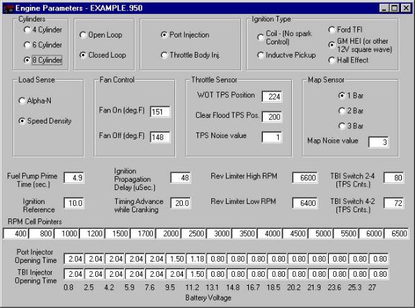
Figure 5 Engine Parameters Screen
Record your selection in the spaces provided.
__________Cylinders – Pick 4, 6, or 8
__________Port Fuel Injection or Throttle Body Injection – Select Multi-Port or Throttle Body fuel injection
__________Ignition Type – See page 63-64 (Appendix 1—Hardware Settings) FOR DETAILED INFORMATION if you are not absolutely sure what type of ignition you have. If you have a computer-controlled (has NO mechanical or
vacuum advance) GM HEI (1981 and up), select “GM HEI”. If you have a Ford TFI, select “Ford TFI”. If you have a Hall effect sensor connected, select “Hall Effect”. If you are connected to a magnetic pickup, select “Inductive Pickup”. If you are not using timing control and DO NOT have a Capacitive Discharge ignition system, select “FuelOnly (coil-)”.
__________Load Sense – Select “Speed Density” or “Alpha N”. See page 11(Section 1.19) for information on these.
__________MAP Sensor – Select whether you have a 1, 2, or 3 bar MAP sensor. See page 8 (Section 1.10) for detailed information on these.
__________Ignition Reference – See page 64 (Appendix 1—Hardware Settings) for the proper number. This is VERY important that it be correct. It provides the ECU with information so that it knows when Top Dead Center (TDC) will occur.
__________TBI Switch 2-4 and TBI Switch 4-2 – If you have a Throttle Body Injection System, see page 68-69 (Appendix 2—TBI Specific Tuning Information) to set this. This is important.
Setting these parameters will allow for the ECU to receive a RPM signal and fire the injectors. If the base map is sufficiently close, the other parameters do not have to be changed to see if the car will start. They will be explained and adjusted later.
23
9. ¨ SAVE PARAMETERS
It is recommended that you save your map to the computer hard drive anytime you make changes, that way you can always go back to a previous version. At this time you should save that map that has the correct engine parameters. To save the map perform the following:
A.Turn the ignition on.
B.Go to “File” and “Retrieve ECU Data”
C.Go to “File” and “Save Data to Disk”
D.Select the directory that you want to save it to
E.Type in a name for the map
F.Either hit “Enter” or click on “OK”
The map is now saved on the computer hard drive in the directory you selected. It may be opened and sent back to the ECU if needed. The default directory is “CMDR 950”.
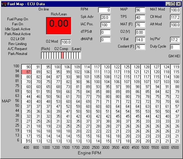
10. ¨ Next, we will verify that all of the sensors are working correctly. Select “Fuel” and “Main Fuel Map”. This brings up the base fuel map. At the top is the Data Monitor, which among other items, shows all the outputs from the sensors. Several of these will be verified before we start the engine. The ignition key needs to be ON to view the data. The following picture shows typical key on values.
If any of these sensors are not reading correctly, see the troubleshooting area and correct the problem before attempting to start the vehicle.
Figure 6 Data Monitor Showing “Key On” Values
24

Check the following sensor outputs. After each, record the value in the space provided.
¨ __________MAP (Manifold Air Pressure) – The manifold air pressure when the engine is not running should be between about 88 and 94 with the engine not running. In higher elevations it will be lower. Possibly as low as 75-80.
¨ __________TPS (Throttle Position Sensor) – The position of the TPS needs to be greater than 5 with the throttle closed and when the throttle is fully opened, it must be less than 255. As the throttle is opened, the TPS value should evenly increase from a low to a high value. There is not a specific value or voltage it needs to be at. But, there are parameters that must be entered depending on what it is. These will be entered later. The TPS on Holley TBI and MPI systems should not need to be changed as they come from the factory preset.
¨ __________MAT (Manifold Air Temp (F)) – The manifold air temperature should be very close to the actual temperature of the air when the engine is off and cold.
¨ __________V Bat – (Battery Voltage) – The battery voltage should not be less than 12 volts. It should be over 13.5 volts with the engine running. Proper voltage is essential to an EFI system. If your battery or charging system is not adequate, it must be fixed.
¨ __________Coolant (F) (Coolant Temperature) – The coolant temperature should be about the same as the manifold air temp (or it should be close to the same as your temperature gauge) if the engine has not been running.
ALL OF THESE SENSORS MUST BE WORKING FOR THE ENGINE TO RUN AND OPERATE. IF THEY ARE NOT READING CORRECTLY, FIND OUT WHY.
11.Now, try to start the car. Make sure the key is off, turn it on, let the fuel pump prime until pressure is built, and start the car. You should hear the pump speed slow down when the system is pressurized. If the base map is close, it should immediately fire and run. If it does not fire or stay running refer to the Basic Tuning-Section 8.0. You should not and do not want to move the gas pedal when trying to start the vehicle.
12.Make sure that the fuel is not excessively rich so much as to damage the engine or catalytic converters. The most obvious sign of this is black smoke coming from the exhaust. If it is, shut it off and refer to the Basic Tuning-Section 8.0.
13.If the engine seems to be operating fairly smoothly, check fluids and check for leaks. Recheck the following sensor outputs at idle and record the values in the space provided. Now is a good time to recheck the fuel pressure with the engine running. Make sure you remove the vacuum reference line.
¨ __________MAP (Manifold Air Pressure) – Engines with mild camshafts should have a MAP value of 20-40. Engines with performance or racing camshafts may have a MAP value of 40-70.
¨__________TPS (Throttle Position Sensor) – The TPS value should be the same as when the engine is not running.
¨__________MAT (Manifold Air Temp (F)) – If the MAT sensor is located in the intake manifold as with Holley
systems, it should slowly rise as the temperature of the intake air increased.
¨__________V Bat – (Battery Voltage) – The battery voltage should be over 13 volts with the engine idling.
¨__________Coolant (F) (Coolant Temperature) – The coolant temperature should gradually increase as the engine
warms up.
¨ __________Fuel Pressure – Record the fuel pressure with the vacuum line disconnected.
NOTE: After the vehicle is started and runs, remove the vacuum reference line to the regulator and recheck and adjust the pressure to the proper settings. It may change slightly from when the engine was not running.
Before proceeding to the next section, check for fuel leaks. Fuel leaks could cause engine damage, personal injury, or death.
CONGRATULATIONS! You have now completed the fire-up procedure and should have a running vehicle.
25

8.0 STEP-BY-STEP BASIC TUNING
The following is a step-by-step guide to perform basic tuning that will be required with all applications.
TIPS:
-Tune one parameter at a time. Don’t change things unless you know what they do.
-Follow the instructions. They provide a methodical tuning plan.
-This section is designed to help you with 75% of the tuning you need to perform. Fine tuning information is covered in Section 9.0. Fine tuning is required to realize the performance that EFI will deliver.
-Until you become more familiar with the software and tuning, don’t spend a lot of time or make large changes to fix small problems. As you tune, they may disappear as other areas are adjusted.
NOTE: It is advised that you save your map every time before you make large changes. That way if you make changes that are incorrect, you can always revert to the previous settings. See Section 6.3 for instructions how to save a map (saving a file to the computer).
NOTE: If your engine starts and idles, you may want to skip to Section 8.0, step 5.
8.1 Startup / Engine Won’t Start
TROUBLESHOOTING NOTE: If the engine starts and stalls, proceed to step 4.
1.CHECK RPM SIGNAL
If the engine will not start at all, first check to make sure the ECU is getting an RPM signal. To check for this, go to “Fuel” and “Main Fuel Map”. When the engine is cranking, look in the upper left area where it says “Fuel Pump On”. These words should be highlighted in orange. If they aren’t, then the ECU is not getting an RPM signal and will not fire the injectors or ignition. It is likely that that the wrong ignition setting is chosen or the wrong rpm input wire is used. See the troubleshooting section-Appendix 4 and check the wiring diagram-Appendix 10 for help. The following picture shows what the fuel map screen should look like when the engine is cranking. Note that the “Fuel Pump On” is highlighted and note that there will be no number in the “RPM” box until the engine actually starts.
Figure 7 Example of Engine During Cranking
26
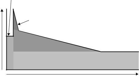
2.CHECK TIMING
If the ECU is getting an RPM signal, the next best thing is to make sure that the ignition is firing. To check this, connect a timing light to spark plug #1, and make sure that it is firing while it is cranking. If it is, try to see approximately what the timing is on the harmonic balancer. If it is not between approximately 0 and 40° BTDC, then that may be why it will not start. Adjust the distributor until the timing is about 10° BTDC.
Cranking |
|
|
Enrichment |
|
|
|
Afterstart |
|
|
Enrichment |
|
Coolant Modifier |
|
|
Fuel |
Fuel Map (Base Fuel Amount) |
|
Amount |
|
|
COLD |
Temperature |
HOT |
Figure 8 Idle Fuel vs. Temperature
3.CRANKING PULSEWIDTH
Figure 8 above is a graphical representation of the fuel that is injected at idle when an engine is started. As you can see, cranking fuel is added until the engine starts. After it starts, the base fuel map value is determined from the main fuel map and is multiplied by the coolant modifier and the afterstart enrichment. Refer to this to help understand how fuel is added after an engine is started.
If the engine still won’t start and you are sure the ignition is firing and is set reasonably close, then you need to change the cranking pulse width. Go to “Fuel” and “Startup Enrichment”(Figure 9). The top line indicates the cranking pulse width (how much fuel is injected when the engine is cranking) based on the coolant temperature. When the key is turned on, the area (temperature) at which the coolant is at should be highlighted in red. If the engine won’t start, the cranking pulsewidth is USUALLY too small. With the key on go into the area highlighted and raise the amount 1-2 milliseconds at a time. Change the cell you are on and the one before and after. A typical V8 should need between 10 and 20 milliseconds when it is cold to start. A TBI system may need more fuel than a Multi-Port system. When the temperature of the engine increases, the cranking fuel needs to decrease (to about 4-10 milliseconds). The bigger the injectors, the less cranking fuel an engine needs. Smaller injectors such as 19 lb./hr. multi-port or 45 lb./hr. TBI injectors may need more cranking pulse width. Keep this in mind.
Continue raising or lowering the cranking fuel in increments of 1-2 milliseconds until the engine starts. Once again, the base maps should allow the engine to start.
The other reason that it may not start is that there is not enough airflow present during cranking. You can open the front throttle plates slightly to ensure enough air is entering. However, it is most likely the problem is from a lack of fuel.
NOTE: The cranking pulsewidth is only while the engine is starting. The second it fires, it no longer affects fuel flow.
27

Figure 9 Startup Enrichment Table
4.STARTUP / STARTS AND STALLS
If the engine starts and then stalls, it most likely needs more air and/or fuel. There are several areas that may need tuning that relate to fuel.
For simplicity’s sake, at this time, we are going to stay in one area, the main fuel map. The other areas that will likely need to be changed are the coolant temperature modifiers and the afterstart enrichment. If these areas are not ideal, we will just tune the fuel map now to compensate. The idea is to allow the engine to stay running and get up to operating temperature where the main fuel map can then be properly tuned. After the main fuel map is tuned with the engine up to operating temperature, you will ONLY use the coolant temperature modifiers and the afterstart enrichment for cold engine performance. Tuning these areas is covered in Required Additional EFI Tuning-Section 9.0.
Go to “Fuel” and “Main Fuel Map”. This brings up the main fuel map. The fuel map has 16 columns and rows. The bottom indicates the engine rpm scale. The left column indicates manifold vacuum (or pressure). The bottom of the map indicates high vacuum conditions. The top of the map indicates low vacuum that occurs at wide-open throttle conditions.
See Figure 11.
Start the engine. The area of the fuel map that the ECU is obtaining the fuel value from will be highlighted in red. The following picture (Figure 10) shows an engine idling at 950 rpm with a manifold pressure of 43 kPa.
Figure 10 Example of Fuel Map with Engine Idling
28
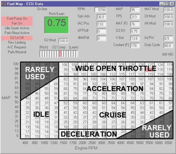
Figure 11 Example of Fuel Map with Graphical Representation
TIP: This red box will move around. Notice where the red box is when the engine starts. If the engine stalls, leave the key on and increase the values in the area where the engine was trying to idle. Raise this area in increments of 5 units at a time. A typical small block or big block with 24-36 lb./hr. injectors should usually only need a number
between 22 and 40 in the fuel map depending on many variables. The bigger the injectors and the smaller the engine, the smaller these values will be. If the car is stalling, it is unlikely it is too rich unless the fuel is very excessive. Keep adding fuel in the area that the engine is running in until it stays idling. Let the engine come up to operating temperature. Be careful not to make the engine too rich as damage to the rings can result.
NOTE: As mentioned, if the engine seems to be struggling for air, open the throttle plates more.
TIP: The ignition timing, which will be adjusted once the engine idle is maintained, can cause the engine to stall if it is off a lot. Keep this in mind.
CAUTION! Make sure the engine coolant temperature is not getting too hot. This can be monitored on the data monitor at the top of the fuel map screen.
5.SET TIMING
After the engine has stabilized, the timing must be synchronized if timing control is being used. If timing control is not being used (as with any mechanical advance distributor), set the distributor advance to the proper specifications. If computer controlled timing is used, bring up the spark map (“Spark” and “Main Spark Map” ). This is the main spark map. The following (Figure 12) is an example of an engine idling with a steady spark advance of 19°.
29
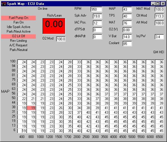
Figure 12 Spark Map with Engine Idling
When the engine is running, the area that it is getting its timing advance from will be highlighted in red. The advance is also shown in the data monitor (spk adv). With a timing light, check the advance at the crankshaft. The value at the crankshaft needs to be the same as the value on the data monitor. If the value on the data monitor is fluctuating too much, then modify the spark advance table to make it more “flat” in the area the engine is running to help set the timing. In other words, set the idle area to the same value, like 15°. It is best to have a dial-back timing light, or a timing tape to do this. If you don’t have either, most engines have a timing tab that goes up to about 14°. Set the advance in the spark map to 14 and use the tab on the engine to synchronize the timing.
TIP: After it is set, it is best to check the timing at a higher rpm such as 3000 to verify that it is the same as the data monitor. Be careful and do not get in the direct path of the fan blades.
NOTE: If the timing does not advance on the engine, but does on the screen, you have the ignition improperly set up. Resolve this immediately.
If you have a crank trigger, the pickup may need to be moved to synchronize the timing.
6.SET IAC (Idle Air Control Motor)
Next the throttle plates should be adjusted. To do this open the data monitor in the main fuel map and look at the “IAC Pos.”. This number should be between 10 and 20 at hot idle in neutral with air conditioning off. If it is higher, open the throttle plates until it moves down. If it is stuck at 10 open the throttle plates slowly until the IAC position reads 10-20. This allows the IAC to have it’s full range when needed for cold starting. It also allows for a more stable idle. The following picture is an example of an engine up to temperature with the IAC at a desirable position of 12 (Figure 13).
30
 Loading...