

Page 1
Page 2

HLP-NV Series
Page 3

Page 4

HLP-NV Series
I. Introduction 2
1. Checks upon Deliver y 3
2. Nameplate Desc ription of HLP-NV Series I nvert er 3
II. Safety Pre cautions 5
1. Before the Power-up 5
2. Dur ing the Power-up 6
3. Duri ng the Operat ion 6
4. Afte r the Power-off 7
III. Standards and Specicat ions 8
1. Particular Specications 8
2. General Specications 9
IV. Storage and Instal lation 11
1. Storage 11
2. Inst allat ion Site and Environment 11
3. Insta llation and Direction 11
V. Wiring 12
1. Main Circuit Wiring Schematic Diagram 12
2. Description of Terminal Block 13
3. Basic Connection Diagram 15
4. Switches 15
5. Precaut ions on Wiring 16
VI. Instruc tion of the LCP Digital Operator 19
1. Description of the LCP Digital Operator 19
2. Programming with LCP 19
VII. Parameter Overv iew 25
VIII. Parameter Descriptions 37
IX. Ma intena nce, Fault I nformat ion and Trouble shooting 90
1. Precautions about Inspection and Maint enance 90
2. Periodical In spection and Ma inten ance items 90
3. Fault Indication and Troubleshooting 91
3. Fault code descript ion and Analysis 92
HLP-NV Series
Page 5

HLP-NV Series
IX. Appendices 96
Append ix 1: Mounti ng Dime nsions of HOLI P NV inverters 96
Append ix 2: Mount ing Dimensions of LCP Digit al oper ator 98
Append ix 3. Braking Resistor Disposition 98
Append ix 4. Simple Example of Appl iaction 99
Append ix 5:User’s feedback 106
HLP-NV Series
Page 6
HLP-NV Series
I. Introduction
Than k you for purchas ing and using the gen eral- purp ose inver te r of
HLP-NV series of mu lti-functions and high performance.
Please read caref ully the operation m anual before putt ing the i nvert er to
use so as to correctly install and operate t he inverter, give f ull play to its
functions and ensure the safety. Please keep the operation manual handy
for future reference, maintenance, inspe ction and repai r.
Due to th e invert er of a k ind of ele ct rica l and elect ronic pr od uc t it
must be in sta lled, tested and adjust ed with parameters by specia lized
engineeri ng persons of motor s.
The ma rk s of
remind you of the s afet y and prevention caut ions d uring the handling,
inst allat ion, runn ing and inspection. Please follow t hese instructions to
make su re the safe use of the inver ter. In case of any doubt please contact
our local agent for consult ation. Our professional persons are w illing and
ready to serve you.
The manual is subject to change without notice.
Danger
Caution
and ot her sy mb ols in the ma nu al
Danger
Caution
indicates wrong use may k ill or injure people.
in di ca te s wro ng us e may damage the in ve rte r or
mechan ical system.
Danger
● Be sure to tur n off the input power supply before wiring.
● Do not touch any internal electrical circu it or component when the
charging lamp is sti ll on af ter t he AC power supply is disconnected,
which means the inver ter still has high voltage inside and it is very
dangerous.
● Do not check components and sig nals on the circuit boards dur ing
the operation.
● Do not dissemble or modify any internal con nect ing cord, wiring or
compone nt of the inverter by yourself.
● Be sure to make correct ground con nection of the earth terminal of
the inverter.
● Never remodel it or excha nge control boa rds and compon ent s by
yourself. It may expose you to an electrical shock or explosion, etc.
HLP-NV Series
- 1 -
Page 7

HLP-NV Series
● Mo t or ov er lo ad prote cti on is inc lu ded in the defau lt set tin gs.
Parameter C01.90 Motor thermal protection is set to value ET R trip.
● Do not ma ke any vol ta ge-withstand ing test with any co mpone nt
ins ide the inverter. These sem i-cond uct or parts are subj ect to th e
damage of high voltage.
● Ne ve r connect th e AC m ain ci rc ui t powe r supply to th e out put
terminals U.V W of the inver ter.
● The main electric circuit boards of CMOS and IC of the inverter are
subject to the ef fect and d amage of st atic electricity. Don’t touch the
main ci rcuit boards.
● Installation, t esting and maintenance must be perfor med by qu alied
professional personnel.
● The inverter should be discarded as industrial waste. It is forbidden
to bur n it.
1. Checks upon Delivery
Th e inver ter has bee n str ictl y and well pa ck ed befo re ex-wo rk . In
co ns id er atio n of var io us fa ctor s d u rin g the tra nsp or tat io n spe ci al
attention should be paid to the followi ng points before the assembly and
installation. If there is anything abnor mal please notify the dealer or the
relevant people of our company.
● Check if the i nver ter has got any damage or defor mat ion during t he
transpor tation and handling.
● Check if the re is one piece of HLP-N V ser ies inverter and one copy of
the instruction manual ava ilable when unpacking it.
● Check the inform atio n on the n ameplate to see if the spe cif icat ions
meet your order (Operating voltage and KVA value).
● Check i f there is somethi ng wrong with the i nne r par ts, wir ing and
circuit board.
● Check if each te rm inal is tightly locked an d if there is a ny foreign
article inside the inver ter.
● Check if t he operator buttons are all rig ht.
● Check if t he option al components you ordered are conta ined.
● Check if t here is a ce rti cate of qu alication and a warr anty card.
Caution
- 2 -
HLP-NV Series
Page 8
HLP-NV Series
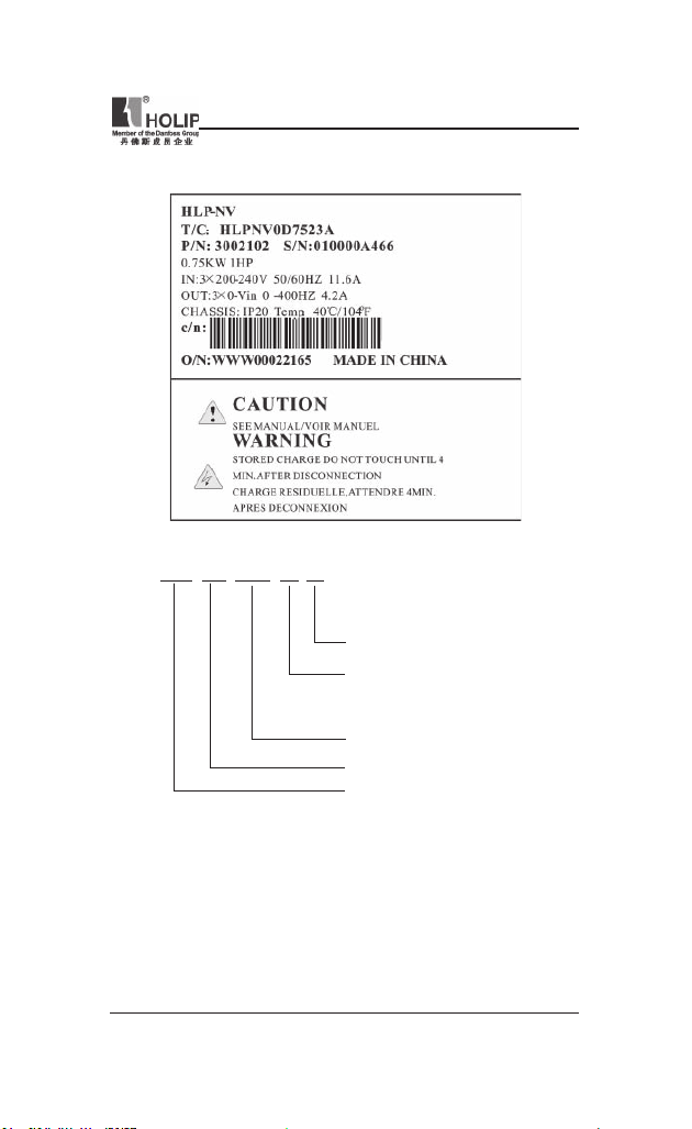
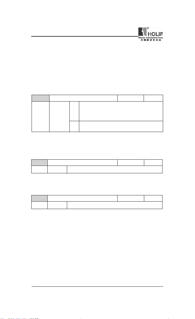
2. Nameplate Description of HLP-NV Series Inverter
Model HLP N V 0D75 23 A
Software Version: A
Voltage Rating: 21:1-Phase AC 220V
23:3-Phase AC 220V
43:3-Phase AC 380V
Inverter Capacity:0 D 75 mean s 0.75KW
Serial No: NV mean s NV ser ies
Trade Mark: HOLIP
HLP-NV Series
- 3 -
Page 9
HLP-NV Series
II. Safety Precautions
1. Before the Power-up
● Check to be sure t hat the voltage of the main circuit AC power supply
matches the input voltage of the i nverter.
● The symbol
correct ground con nection of the earth terminals of the motor and the
inverter for safety.
● No conta ctor should be inst alled betwee n the power supply and the
inverter to be used for star ting or stopping of the i nvert er. Otherwise
it will affect the serv ice life of the inverter.
● R(L), S,T( N) ter mi nals are powe r input ter minal s, never mixed
with U.V.W t erm inals. Be sure that the wiri ng of the main circuit is
cor rec t. Other wise it will cau se damage s of the inve rt er when the
power is appl ied to it.
● The terminal of
to li ne zero. Otherw ise it will easily cause the prote ction or er rors of
the inverter.
, repr esents grou nd te rmi na ls . Be su re to ma ke
Danger
must be grou nded separately and never connect ed
Caution
● Do not ca rr y t he front cover of the inver ter directly when handling.
It should be hand led with the base to prevent the fall-off of the f ront
cover and avoid the dr opp ing of the inve rt er, which may pos sibly
cause the injur ies to pe ople and the damages to the i nvert er.
● Mount the i nver ter on a met al or other nonc ombustible mater ial to
avoid the risk of re.
● Insta ll the inverter in a safe loc ation, avoid ing hig h tempe rat ure,
direct sunlight, hu mid ai r or water.
● Kee p the inv erte r fro m th e re a ch of chi ldr e n or pe r so ns not
concer ned.
● The in ve r te r can only be use d at the pla ce s acc redit ed by our
com pa ny. Any unau th or iz ed work ing envi ronment may have th e
risks of re, gas explosion, ele ctric shock and other incidents.
● Install a he at sink or other cooling device when inst alling more than
one inverter in the same enclosure so that t he temperature in side t he
enclosu re be kept below 40℃ to avoid overheat or the risk of re.
Caution
- 4 -
HLP-NV Series
Page 10
HLP-NV Series
● Be su re to tu r n of f t h e po we r s up ply bef o re d i sse mbl i n g or
assembl ing the operation key panel a nd xing the front cover to avoid
bad cont act causing faults or non- display of the oper ator.
● Do not in stall the inverter in a space with explosive gas to avoid the
risk of explosion.
● If the i nvert er is used at or above 1000m above seal level, the cooli ng
efciency will be worse, so please run it by de-rating.
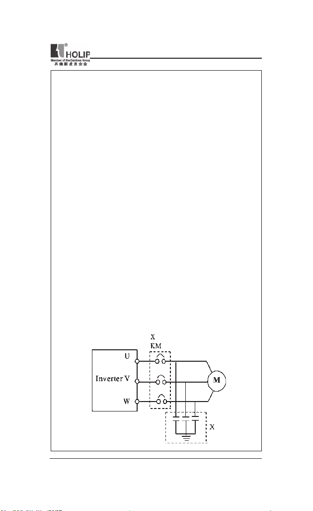
● Do not install any c ontactor and other comp onents of cap acit or or
var istor on the o utp ut side of the inverter. Other wise it will cau se
malfunctions and damages of components of the inverter.
● Do not ins tall any switch co mp on en t like ai r cir cu it brea ke r or
cont actor at t he output of the i nverter. If any of such components
mu st be ins t al led beca use of t he req uir e me nts of pro ces s and
others, it must be ensu red that the inverte r has no out put when the
swit ch acts. In addit ion, it is forbidden to install any c apacitor for
improvement of power factor or any varist or agai nst thunder at t he
output. Othe rwise it will cause malfunctions, tr ipping protection a nd
damages of components of the inverter. Please remove them as shown
in the below diagr am.
● It wi ll affect the service life of the inverter if a contact is connected
to the front end of input of the inver ter t o cont rol its starts and st ops.
Generally it is re qu ir ed to cont rol it thr ou gh Con trol term inal s.
Special attention should be p aid t o its use in the case of frequent
star ts and stops.
● Pleas e use an indep ende nt powe r supply for the i nver ter. D o avoid
using the common power supply with an electrical welder and other
equipme nt wi th st ro ng di st urbance. Ot herwise it wi ll ca us e the
protection or even d amage of t he inver ter.
HLP-NV Series
- 5 -
Page 11
HLP-NV Series
2. During the Power-up
● Do not plug the conne ctors of the inve rter du ri ng the power up to
avoid any surge i nto the main control board due to pluggi ng, which
might cause the damage of the inverter.
● Always have the protective cove r in place before the power up to
avoid electrical shock injur y.
Danger
3. During the Operation
● Never c onnect or discon nect the motor set while the inverter is in
run ning. O ther wise it will cause over-current trip and even bur n up
the mai n circu it of the inverter.
● Never rem ove th e fr ont cover of the inverter w hile the inve rt er is
powered up to avoid any inju ry of electric shock.
● Do not come close to the machine when the fault resta rt fu nction is
use d to avoid any thing unexp ect ed. The m otor may automa tic ally
resta rt af ter its stop.
● The f unction of STOP Swit ch is on ly valid af ter set ti ng, which is
different with the use of emergent stop switch. Please pay attention to
it when usi ng it.
Danger
● Do not touch the heat sink, braking resistor, or other heat elements.
Caution
These can become very hot.
● Be sure that the motor and m achine is withi n the applicable spe ed
ranges before sta rting operat ion because the inver ter is quite easy to
run f rom lower speed to higher sp eed.
● Do not check the sign al s on ci rcuit bo ar ds wh ile the inve rt er is
run ning to avoid danger.
● Be caref ul when changing the inver ter settings. The inverter has been
adju sted and set before ex-work . Do not a djust it wanton ly. Please
make proper adjustments according to the requ ired f unct ions.
● Do consider the vib ration, noise an d the speed limi t of the motor
bearings and the mechanical devices whe n the inverter is ru nni ng at
or above the f requency of 50Hz.
- 6 -
HLP-NV Series
Page 12

HLP-NV Series
4. After the Power-off
● Touching t he electrical parts may be fatal - even afte r the equipment
ha s been disco nn ec ted f rom mains. Also ma ke su re th at ot he r
voltage input s have been disconnected, (li nkage of DC intermediate
circuit).
● Be aware that there may be high volt age on the DC lin k even when
the LEDs a re tu rned of f.
● Before touching any potentially live parts of the VLT Micro, wait at
least as follows:
200 - 240 V, 0.4 – 1.5 kW: wait at lea st 4 minutes.
380 - 480 V,0.75 – 2.2 kW: wait at least 4 minutes.
Shor ter time is allowed only if indicated on the nameplate for t he
specic unit.
HLP-NV Series
- 7 -
Page 13
HLP-NV Series
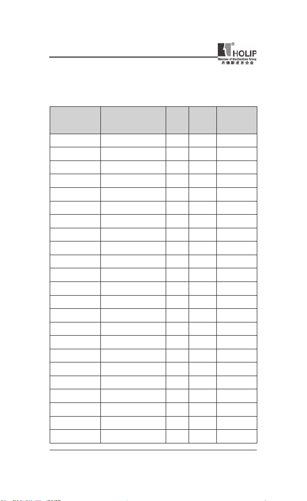
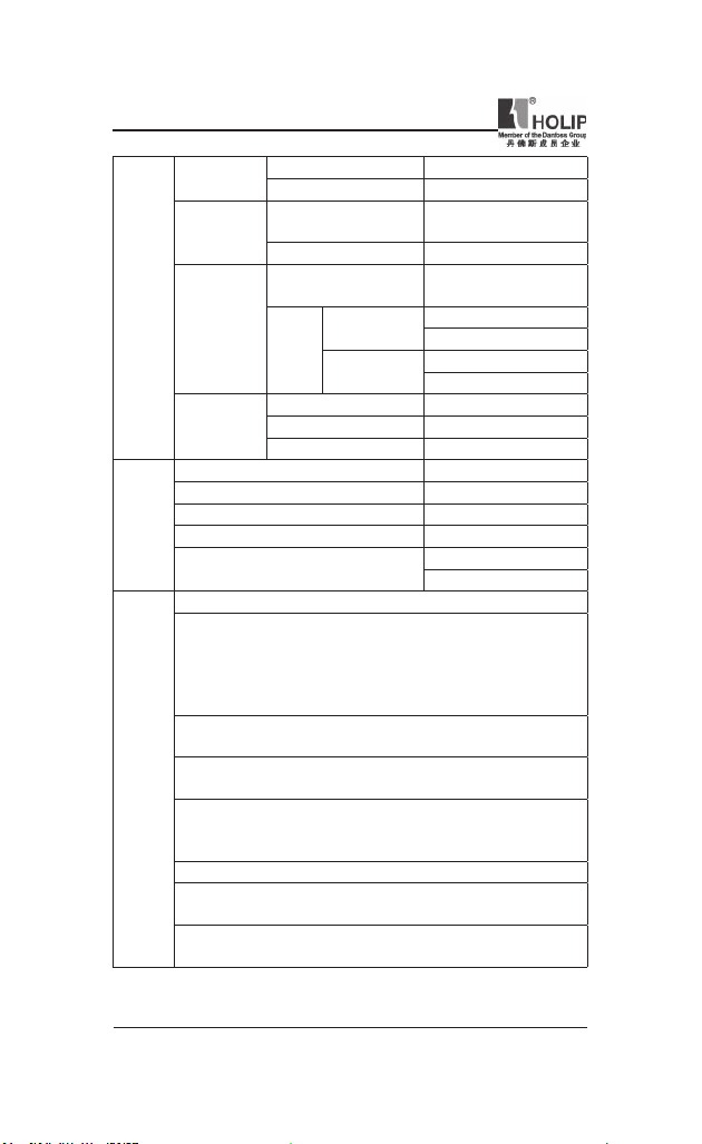
III. Standards and Specications
1. Particular Specications
Outp ut
Model Input Voltag e
HLPN V0D1821A 1×200-240V 50/60H z 0.18 1.2 0.18
HLPN V0D3721A 1×200-240V 50/6 0Hz 0.37 2.2 0.37
HLPN V0D7521A 1×200-240V 50/60 Hz 0.75 4.2 0.75
HLPN V01D521A 1×200-240V 50/60Hz 1.5 6.8 1.5
HLPN V02D221A 1×200-24 0V 50/60Hz 2.2 9.6 2.2
HLPN V0D2523A 3×200-240V 50/60Hz 0.25 1.5 0.25
HLPN V0D3723A 3×200-24 0V 50/60Hz 0.37 2.2 0.37
HLPN V0D7523A 3×200-24 0V 50/60Hz 0.75 4.2 0.75
HLPN V01D523A 3×200-240V 50 /60Hz 1.5 6.8 1.5
HLPN V02D223A 3×200 -240V 50/60Hz 2.2 9.6 2.2
HLPN V03D723A 3×200-24 0V 50/60Hz 3.7 15.2 3.7
HLPN V0D3743A 3×380-480V 50/60Hz 0. 37 1.2 0.37
HLPN V0D7543A 3×380-48 0V 50/60Hz 0.75 2.2 0.75
HLPN V01D543A 3×380-480V 50/60Hz 1.5 3.7 1.5
HLPN V02D243A 3×380- 480V 50/60Hz 2.2 5.3 2.2
HLPN V03D043A 3×380- 480V 50/60Hz 3.0 7.2 3.0
HLPN V04D043A 3×380- 480V 50/60H z 4.0 9.0 4.0
HLPN V05D543A 3×380-480V 50/60Hz 5.5 12 5.5
HLPN V07D543A 3×380- 480V 50/60Hz 7.5 15.5 7.5
HLPN V001143A 3×380-48 0V 50/60Hz 11 23.0 11
HLPN V001543A 3×380 -480V 50/60Hz 15 31.0 15
HLPN V18D543A 3×380-480V 50 /60Hz 18.5 37.0 18.5
HLPN V002243A 3×380-480V 50/60 Hz 22 43.0 22
Power
(KW)
Cur rent
(A)
Suitable
Motor
(KW)
- 8 -
HLP-NV Series
Page 14
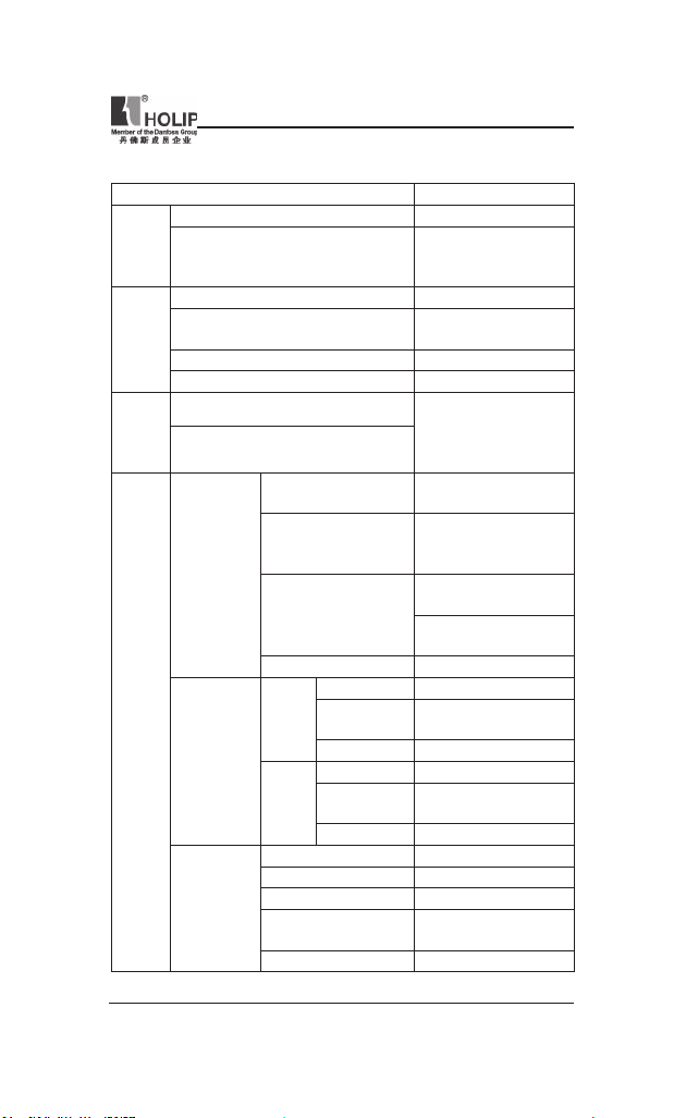
2. General Specications
Inverter Ser ies H LP-NV
Frequency 48~62HZ
Power
supply
Supply Voltage
Output voltage 0~100% of supply volt age
Output frequency
Motor
output
Over load 150% of rated cu rrent
Acc/De c time 0.05~3600s
Runn ing control
Control
Frequency sett ing
Number
Progr ammable
digital inputs
Control
terminals
Anology
inputs
Anology
output s
Voltage level
Logic Voltage level
Input resistance 4KΩ
Number 1;ter minal nos.: VI N
Voltage
Voltage level
Input resistance 10KΩ
Number 2; ter minal nos.: VI N,AIN
Cur rent
Cur rent ra nge
Input resistance 200 Ω
Number 1;Te rmi nal nos.: AO
Output Cur rent ra nge 0/4-20mA
Max.Load 500 Ω
Accuracy
Resolution 8bit
380~480V±10% for 380V
single/three phase
200~240V±10% for 220V
0-200H Z(V VC+),
0-400HZ(V/F)
LCP operate;
Multi input ter minals;
RS 485 ser ial
commu nication
5, term inal nos.: RUN
F/R,RST,JOG,EMS
0~24V DC (“PN P” OR
“NPN ”) ; Maximum
input: 28V DC
PNP: “0”<5VDC;
“1”>10VDC;
NPN: “0” >19VDC;
“1” <14VDC
0-10V DC ;
Maximum input 20V DC
0/4-20mA(scaleable);
Maximum input: 30mA
Max.er ror:0.5% of full
scale
HLP-NV Series
;
,
HLP-NV Series
- 9 -
Page 15
HLP-NV Series
24V DC
RS 485
Control
terminals
Realy out pus
10V DC output
Enclosure IP20
Ambient temper ature -10℃~50
Max.relative hum idity 5%-95%
Surroundings
Vibration test 1.0g
Max.altitude above sea level
Electronic the rmal motor prot ection against overload.
Temperature monitoring of the heatsink ensures that the fre quency
converter tr ips if the temperatu re reaches 95 °C ± 5°C. An overload
temperatu re can not be reset until the temperature of t he heatsink
is below 70 °C ± 5°C (Guideline - these temperatures may vary for
different power si zes, enclosures etc.).
The frequency converter is protected against short-circuits on motor
terminals U, V, W.
The frequency converter is protected against ear th faults on motor
Protection
terminals U, V, W.
Functions
Monitor ing of the inter mediate circuit voltage ensures that t he
frequency conve rter trips if the intermediate circuit voltage is too low
or too hig h.
If a motor phase is missing, the frequency converter may tr ip.
If mains fault occurs, the frequency converter will ramp down to stop
and issues a war ning.
If a mains phase is missing, the frequency conver ter trips or issues a
warn ing (dependingon the load).
Terminal number EV
Max.load 200m A
Terminal number
Ground for RS485 COM
Terminal number
Resistive load
Max
load
Inductive load
Terminal number +10V
Output voltage 10.5±0.5V
Max.load 25mA
RS+(TX+,RX+),
RS- (T X-,RX-)
1,FA-FB(make),
FA-FC(break)
250V AC 2A
30V DC 2A
250V AC 0.2A
24V DC 0.1A
1000m
3000m(derati ng)
℃
- 10 -
HLP-NV Series
Page 16

HLP-NV Series
IV. Storage and Installation
1. Storage
The invert er mu st be kept in its or iginal package box before in stallation.
Pay at tention to the followings when keeping it in storage if the inver ter
is not used for the time being:
● It must be stored in a d ry pla ce without rubbish or dust.
● The suitable temperat ure for storage is between -20℃ and +65℃.
● The relative humidity required is 0-95% without condensation.
● There is no corrosive gas or l iquid in t he storage ambience.
● It’s better to lay the inverter on a rack and keep it in a proper package.
● It is better not to store the inverter for long time. Long t ime storage of
the inver ter wil l lead to the deterioration of electrolytic capacity. If it
needs to b e stored for a long ti me make sure t o power it up one time
withi n a year and t he power-up ti me should be at least above ve hours.
When powered up t he voltage must be increased slowly with a voltage
regulator to the rated volt age value.
2. Installation Site and Environment
The inverter should be instal led at the following location:
● Ambient temper ature -5℃ to 40℃ with good ventilation.
● No water d rop and low moisture.
● Free from direct sunshine, h igh temperat ure and heavy dust fall.
● Free from corrosive gas or liquid.
● Less dust, oil gas and metallic pa rticles
● Free from vibration and easy for ser vice and inspection.
● Free from the interference of elect romag netic noise.
Attention : The ambient condit ions of the invert er will aff ec t its
service life.
3. Installation and Direction
● Th er e mu st be en ou g h sp ace lef t ar ound the inv er te r for eas y
maintenance and cooling.
● The inverter must b e installed vertically wit h the smooth ventilation
HLP-NV Series
- 11 -
Page 17

HLP-NV Series
for effect ive cooling.
● If t here is a ny instabi lity when installi ng t he inverter, please put a at
board u nder the invert er bottom base and inst all it again. If the inverter
is installe d on a loose surfa ce, st ress may cause damage of part s in the
main ci rcuit so as to damage the inverter.
● The inverter should be in stalled on non-combustible mater ials, such as
iron plat e.
● If sever al inver ters are inst alled , up per an d lower, toget her in one
cabine t, pleas e add heat dissipation pla tes and lea ve enoug h space
between the inverters.
- 12 -
HLP-NV Series
Page 18
V. Wiring
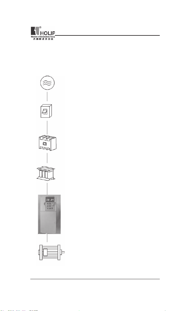
1. Main Circuit Wiring Schematic Diagram
Power supply:
● Verif y that the i nver te r’s r ate d volta ge coi ncid es
with AC p ower supply voltage to avoid a damage
of the inver ter.
No fuse breaker:
● Refer to the related list.
Ground fault circuit interrupter:
● Use one of anti-high harmonic.
Electromagnetic cont actor:
● Note: Do not use the electromagnetic contactor as
the on/off button of power supply for t he inver ter.
AC reactor:
● It is re commended to in st al l an AC reactor for
power factor improvement if the input capacit y is
more tha n 1000KVA.
Inverter:
● Be sur e to make correct c onnections of the main
ci rcu it wire s an d con t ro l sig nal wire s of the
inverter.
● Be s ure to make corre ct sett ing of para meters for
the inverter.
HLP-NV Series
HLP-NV Series
- 13 -
Page 19
HLP-NV Series
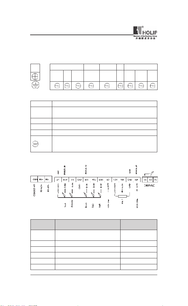
2. Description of Terminal Block
1)Arr angeme nt of Main ci rcuit Term inals
POWER MOTOR
R
L)
(
Function Description of Main circuit Terminals
Symbol Function Description
R S T
U.V.W Out put ter minal of the inve rter
+UDC BR Conne ctor for br aki ng resistor (optional).
-UDC Connector for DC reactor
2) Arra ngement of Control Circuit Terminals
In pu t ter min al of AC li ne power. (220V class:for bot h
single/three phase, si ngle phase connected to L and N)
Grou nd ter minal: the third method of g rounding for 220V
and special grou nding for 380 V of Electrical Engineering
Regulations.
T
S
-UDC +UDC BR U V W
(N)
Function Description of Control Ci rcuit Terminals
Symbol Function Descr iption
EV
RUN Multi- Dig ital Input Start
F/R Multi- Dig ital Input Reverse
GND Digital Ground (for 24V power)
RST Multi- Dig ital Input Reset
JOG Multi- Dig ital Input Jog
- 14 -
Common Terminal of Digital and
Control Signals ( +24V Power)
HLP-NV Series
Default setting
setting
Page 20
HLP-NV Series
Symbol Function Descr iption
EMS Multi- Digital Input Bit0
AO Multi- Analog Output 0/4-20m A
+10V Power Supply for Analog Setti ng +10V
VIN Multi- A nalog input Voltage
GND Analog Ground
AIN Multi- A nalog input 0/4~20mA
FA FB FC Multi- Dig ital Output (Relay)
COM RS+ RS -
RS485 Com munication port
Default setting
setting
FA-FC:break
FA-FB:make
COM:Common for
RS+ and RS -
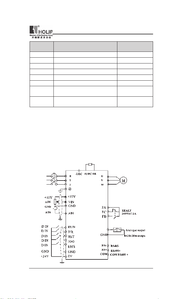
3. Basic Connection Diagram
The wiring of t he inver ter is d ivided i nto two parts, main circuit terminal
connectio ns an d cont rol ci rc uit te r mi na l connec tion s. The user can
see the m ai n ci rcuit terminal s an d th e contr ol circu it term in als af ter
remov in g the cover of encl os ur e. The ter mi nals must be co nnected
correctly as t he following wiring circuit diagrams.
The following diagram shows the Default setting standard con nection of
Model HLP-N V
HLP-NV Series
AO
- 15 -
Page 21
HLP-NV Series
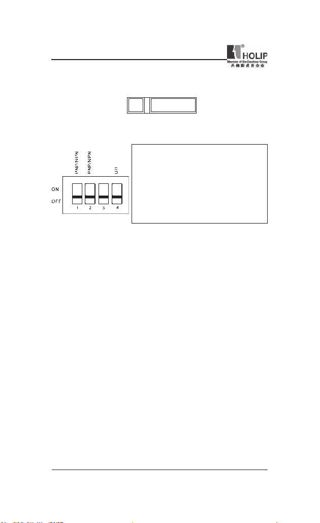
4. Switches
i. Bus ter mination:
OFF
Mark:Swit ch BUS TER enables termination of the RS485 port, term inals
RS+, RS-.
ii. Switches 1-4:
ATT EN TI ON: Para me te r C06.19 must be set acco rd in g to Switc h 4
position.
Warni ng: D o not oper ate swi tch es with pow er on the fr equ e nc y
converter.
BUS TER
ON
Switch 1: *OFF = PNP t erm inal JO G
ON = NPN te rmi nal JOG
Switch 2: *OFF = PNP t erm inals RUN,
F/R,R ST,EMS
ON = NPN te rmi nals RUN ,
F/R,R ST,EMS
Switch 3: No fun ction
Switch 4: *OFF = Termi nal VIN 0 - 10 V
ON = Termin al VI N 0/4 - 20 mA
* = default s etti ng
5. Precautions on Wiring
1) For the main circuit wiring:
● Wh ile wiring the sizes and specications of wires should be selected
an d the w iri ng sho ul d be exe cu t ed acc ord i ng to the elect ric al
engineeri ng regu lations to ensure the safety.
● It is better to use shielded wire or wire and conduit for power cord and
ground the shielded layer or t wo ends of wire conduit.
● Be sure to install a Non Fuse Breaker ( NFB) bet ween the power supply
and the in put te rminal s (L1.L2. L3). (If usin g grou nd fau lt circ ui t
inter rupter, please choose one corre sponding to high frequency)
● Ne ve r con ne ct AC powe r t o the outp ut ter min al ( U.V.W) of the
inverter.
● Outpu t wi res mus tn’t b e in tou ch of the metal part of t he inver ter
enclosu re, or it will result in ear th short-ci rcuit.
● Phase -s hift ing capacitors , LC, RC noise fi lte rs , etc, can never be
connected to t he output terminals of the inverter.
● The main ci rcuit wire must be enough far away from other control
equipments.
- 16 -
HLP-NV Series
Page 22
HLP-NV Series
● W hen th e wiring be tw ee n the invert er and the motor exc ee ds 15
meter s (shielded wire) or 50 meters (No shielded wire), much higher
dV/dT will be produced inside the coil of t he motor, which wi ll cause
the destr uction to the interlay or insulation of t he motor. Please use a
dedicated AC motor for the inver ter or add a react or at the inverter.
● Plea se lower the car rier frequ enc y whe n there is a longer di stance
bet ween the inverter a nd the motor. Beca use t he higher t he carr ier
frequency is t he bigger t he leak age cur rent of h igh-order ha rmon ics in
the cables will b e. The leakage current will have unfavorable effect on
the inverter a nd other equipme nt.
Specications of Non Fuse Breaker and Wire
Model
(A)
Input wire
mm
2
Output wire
2
mm
Control wire
2
mm
NFB
HLPNV0D1821A 16 2.5 2.5 0.5
HLPNV0D3721A 16 2.5 2.5 0.5
HLPNV0D7521A 16 2.5 2.5 0.5
HLPNV01D521A 16 2.5 2.5 0.5
HLPNV02D221A 32 4 4 0.5
HLPNV0D2523A 16 2.5 2.5 0.5
HLPNV0D3723A 16 2.5 2.5 0.5
HLPNV0D7523A 16 2.5 2.5 0.5
HLPNV01D523A 32 2.5 2.5 0.5
HLPNV02D223A 32 4 4 0.5
HLPNV03D723A 32 4 4 0.5
HLPNV0D3743A 16 2.5 2.5 0.5
HLPNV0D7543A 16 2.5 2.5 0.5
HLPNV01D543A 16 2.5 2.5 0.5
HLPNV02D243A 16 2.5 2.5 0.5
HLPNV03D043A 16 2.5 2.5 0.5
HLPNV04D043A 32 4 4 0.5
HLPNV05D543A 32 4 4 0.5
HLPNV07D543A 40 6 6 0.5
HLPNV001143A 63 6 6 0.5
HLPNV001543A 100 6 6 0.5
HLPNV18D543A 100 10 10 0.5
HLPNV002243A 100 16 16 0.5
Attention: The parameters i n the list are only for reference and should not
be regarded as st anda rd.
HLP-NV Series
- 17 -
Page 23

HLP-NV Series
2) For control circuit wi ring (signal line)
● The signal line should be separately laid in a different conduit with t he
main ci rcuit wire to avoid any possible i nterference.
● Please use the shielded cable wit h the size of 0.5-2mm2 for signal lines.
● Use the control terminals on the control panel correctly accor ding t o
your needs.
3) Grounding
● Grounding terminal E. Be sure to make cor rect g round ing
220V class: The third grounding method (Grou nding resistance should
be 100Ω or lower.)
380V class: The special third grounding met hod (Grounding resistance
should be 10Ω or lower.)
● Choose grounding w ires according to the basic length and siz e of the
technical require ments of the electric equipment.
● Do avoid shar ing ground ing wire with other large power equ ipment
such as el ec tr ic welder, power ma ch in e, et c. The gr ou nd in g wir e
should be kept away from the power supply wire s for la rge power
equipment.
● The grounding method for several inverters together should be done as
the rst and sec ond diag rams below. Avoid the third loop.
● The groundi ng wire must be as short as p ossible.
(1) Good (2) Good (3) Not good
- 18 -
HLP-NV Series
Page 24
HLP-NV Series
VI. Instruction of the LCP Digital Operator
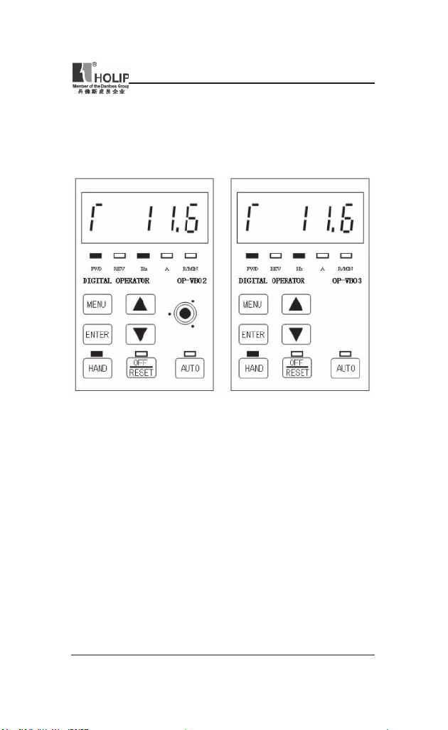
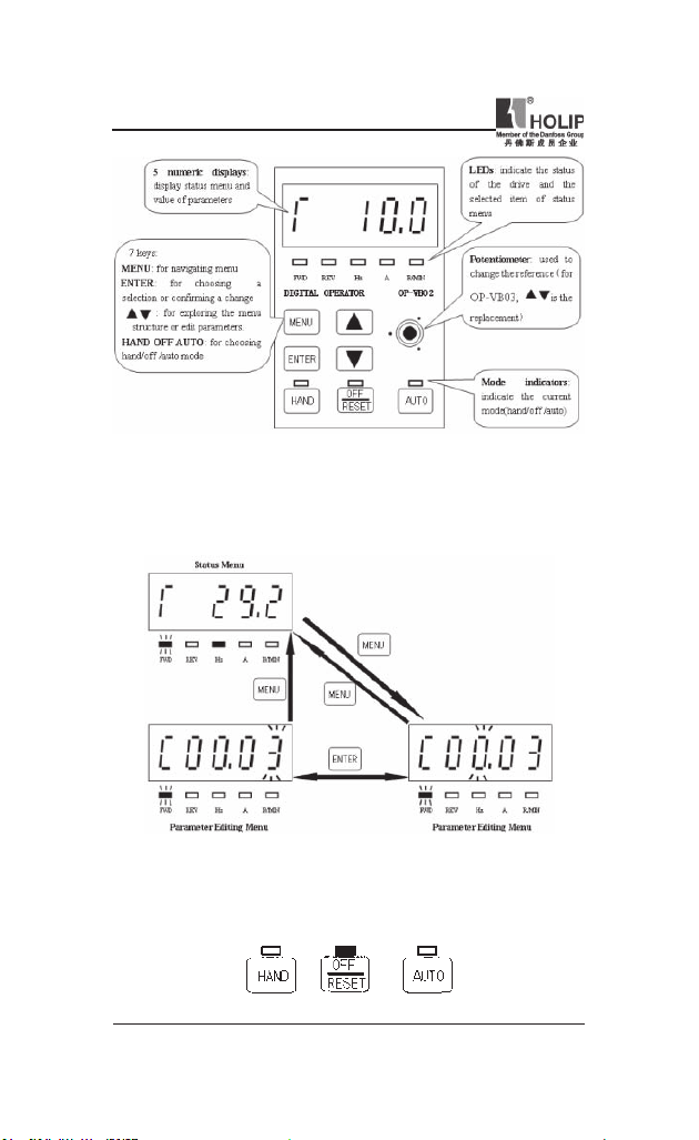
1. Description of the LCP Digital Operator
LCP with potentiometer
2. Programming with LCP
2.1. LCP introduction:
1. 5 numeric d isplays
2.
8 LEDs: FWD、REV、Hz、A、R/MIN、HAN D、OFF/RESET、AUTO
3. 7 keys: MENU、ENTER、▲、▼、HAN D、OFF/RESET、AUTO
4. 1 potent iometer (only for type OP-VB02).
LCP without potentiometer
HLP-NV Series
- 19 -
Page 25
HLP-NV Series
2.2
General Operation
.
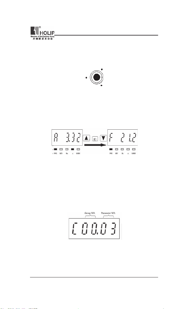
The me nu syst em allows op er ators to nav igate th ro ug h hierarchica l
menus which contain related menu items. The top-level menu c onta ins
two menu items: statu s menu、parameter editing menu. These two items
can be explored by pressing MENU key:
2.3
Mode keys and potent iometer
.
Mode Keys are u sed to send Hand, OFF/Reset, Auto request to the dr ive.
It is related to the reference site selection ( Local or Remote).The yellow
LEDs ind icate the certain active mode.
- 20 -
HLP-NV Series
Page 26
HLP-NV Series
The HAND, OFF/RESET a nd AUTO key ca n be dis abled by chang ing
parameter(C00.40、C00.41、C00.42).
Potentiometer: used for set ting t he refere nce only.
The pot entiometer can be used in bot h hand and auto mode wit h different
functionality:
In Ha nd mode the potentio me te r will work as the arr ow key s – i .e.
controlli ng the local refere nce fr om 0 to max reference (C03.03). If the
LCP does not c ont ain a pot entiom ete r, the ar row keys ar e used to set
reference:
In auto mode the potentiometer will act a s an ext ra analog input to the
system. It is selected/deselected as the other analog input s (see C03.15 to
C03.18).
C06.81, C06.82 are used to scale the potentiometer input.
2.4 Parameter editing menu and st atus menu
2.4.1 Parameter editing menu:
HLP-NV Series
- 21 -
Page 27
HLP-NV Series
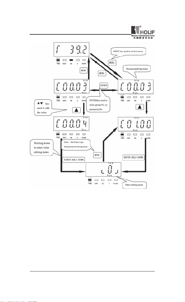
Parameter set ting example:
How to set C03.17 to 21
1. Pressing MENU key to let the display go to parameter ed iting menu.
2. Pressing▲▼key to select group No.(C03.00)
3. Pressing ENTER key t o edit par ameter No.,then p ressing▲▼key to
select paramet er No. (C03.17).
4. Hold in g down EN TER key to go to the va lue edtin g menu , then
pressi ng▲▼to edit the value of the parameter to 21,then holding down
ENTER key to conrm t he change till “END”was displayed.
- 22 -
HLP-NV Series
Page 28
HLP-NV Series
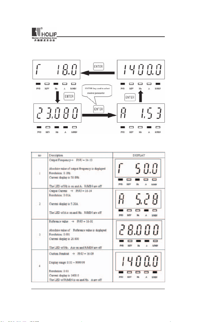
2.4.2 Readout and indicator:
The readout par amete rs toggled by pressing ENTER key:
The below table shows the screen of displayi ng every readout parameter
HLP-NV Series
- 23 -
Page 29
HLP-NV Series
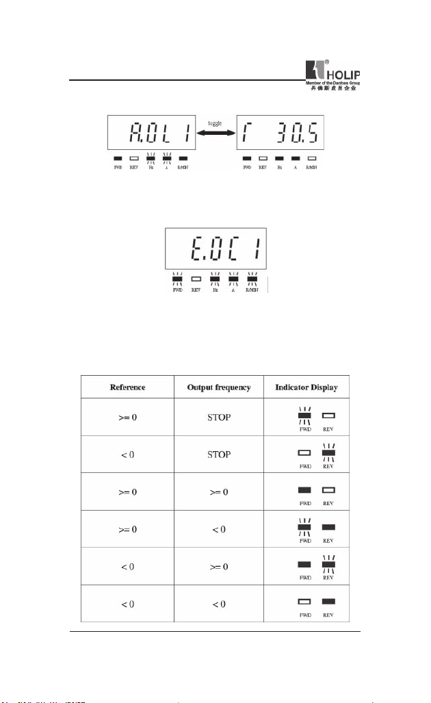
Warning descr iption:
when war ning o ccur red , the LEDs of Hz、A w ill ash a nd R/MIN will
be lit.
Alar m description:
when ala rm occur red, the LED s of Hz、A and R/ MIN will f lash,an d
the drive will trip. A trip ca n be cancelle d by pressing reset or, in some
cases, aut omatically. A locked trip ca nbe cancel led by cutting off mains
and restarting the drive.
The motor direction is indicated by the led s of FWD and REV:
- 24 -
HLP-NV Series
Page 30
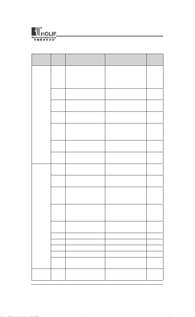
VII. Parameter Overview
Function
Item
Operation
/ Display
Load /
Motor
Fuction Description
Code
Op er. St at e at Power-
C00.04
up [Hand]
Cu st om Re ad ou t Min
C00.31
Scale
Custom Readout Max
C00.32
Scale
C00.40 [Hand on] Key on LCP
[Off / Re se t] Ke y on
C00.41
LCP
C00.42 [Auto on] Key on LCP
C00.60 Menu locked
C01.00 Conguration Mode
Motor Cont rol
C01.01
Principle
C01.03 Torque Character istics
Local Mode
C01.05
Cong urat ion
Motor Power
C01.20
[kW] [HP]
C01.22 Motor Voltage 50 - 999 V **
C01.23 Motor Frequency 20 - 400 Hz 50 Hz
C01.24 Motor Current 0.01 - 26.00 A **
C01.25 Motor Nom inal Sp eed 100 - 9999 r pm **
Automatic Motor
C01.29
Tuning (AMT )
C01.30 Stator Resistance (R s)
HLP-NV Series
Range&Function
explanation
[0] Resume
*[1] Forced sto p, ref =
old
[2] Forced stop, ref = 0
0.00 – 9999.00 0.00
0.00 – 9999.00 100.00
[0] Disabled
*[1] Enabled
[0] Disable All
*[1] Enable All
[2] Enable Reset O nly
[0] Disabled
*[1] Enabled
[0]Disabled
[1]Enabled
*[0] Speed open loop
[3] Process
[0] V/F
*[1] VVC+
*[0] Constant torque
[2] Automatic Energy
Optim.
[0] Speed Open Loop
*[2] As cong i n param.
C01.00
0.09 kW / 0.12 HP .... 11
kW / 15 HP
*[0] Off
[2] Enable AMT
[Ohm] * Dep. on mot or
data
Default
setting
1
1
1
1
0
0
1
0
2
**
0
**
HLP-NV Series
- 25 -
Page 31

HLP-NV Series
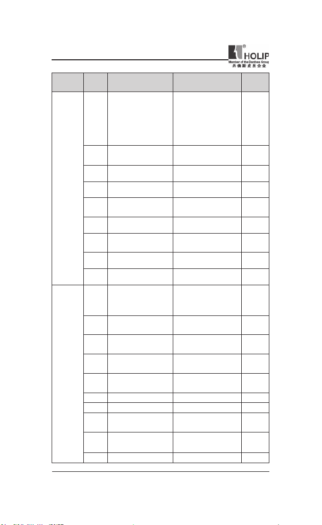
Function
Item
Load
/ Motor
Fuction Description
Code
Stator L eakage
C01.33
Reactance (X1)
C01.35 Main Reactance (X2)
Moto r Mag net is ation
C01.50
at 0 Speed
Min Speed Norm.
C01.52
Magnet. [Hz]
C01.55 V/F Character istic - V 0 - 999.9 V * 0.0 V 0V
C01.56 V/F Character istic - F 0 - 400 Hz 0H z
Low Speed Load
C01.60
Compen sation
High Speed Load
C01.61
Compen sation
C01.62 Slip Compensation -400 - 399 % 100%
Slip Compensation
C01.63
Time Constant
C01.71 St art Delay 0.0 - 10.0 s 0.0S
C01.72 Start Fu nction
C01.73 Flying Sta rt
C01.80 Function at Stop
Mi n Spee d for Fu nc t.
C01.82
at Stop [H z]
Motor The rmal
C01.90
Protection
C01.93 Ther mistor Resource
Range&Function
explanation
[Ohm] * Dep. on mot or
data
[Ohm] * Dep. on mot or
data
0 - 300 % 100%
0.0 - 10.0 Hz 0.0H z
0 - 199 % 100%
0 - 199 % 100%
0.05 - 5.00 s 0.10s
[0] DC hold / delay time
[1] DC brake / delay
time
*[2] Coast / delay time
*[0] Disabled
[1] Enabled
*[0] Coast
[1] DC hold
0.0 - 20.0 Hz 0.0Hz
*[0] No protection
[1] Te rmistor warning
[2] Therm istor t rip
[3] Etr warning 1
[4] Etr trip 1
*[0] None
[1] Analog Input V IN
[6] Digital I nput JOG
Default
setting
**
**
2
0
0
3
0
- 26 -
HLP-NV Series
Page 32

HLP-NV Series
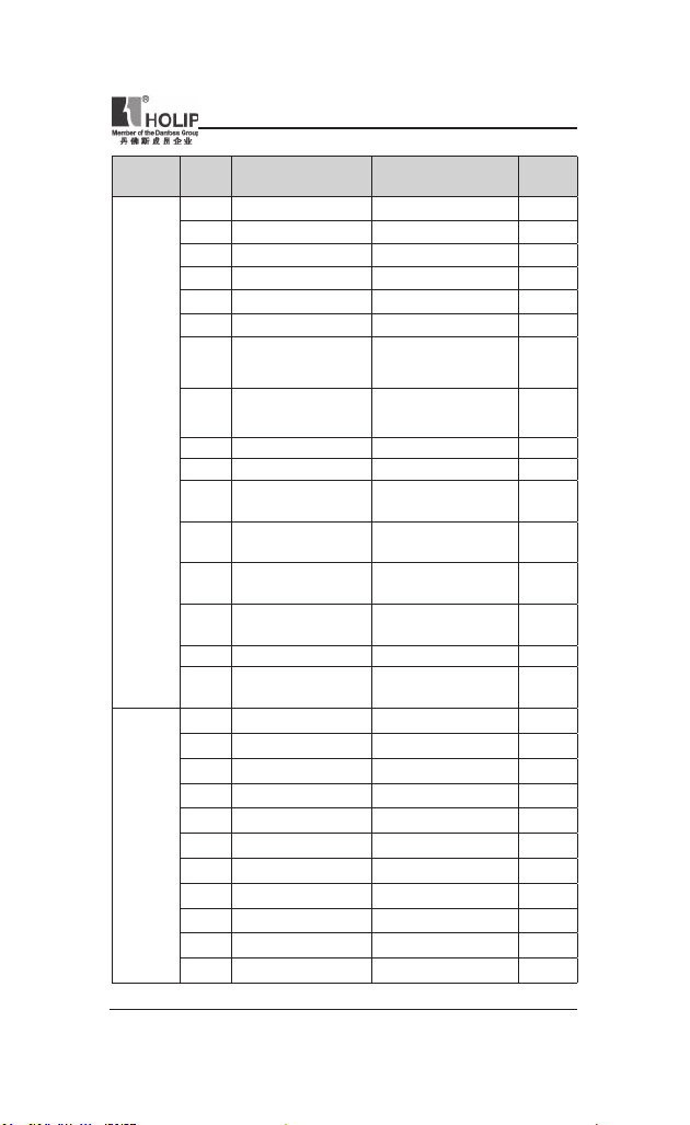
Item
Brakes
Reference
/ Ramps
Function
Fuction Description
Code
C02.00 DC Hold Current 0 - 100 % 50%
C02.01 DC Brake Cur rent 0 - 100 % 50%
C02.02 DC Br aki ng Time 0.0 - 60.0 10.0S
C02.04 DC Brake Cut In Speed 0.0 - 400.0 Hz 0.0Hz
C02.10 Brake Function
C02.11 Brake Resistor (ohm) 5 -5000Ω *
C02.16 AC Brake, Max current 0 - 400 % 100%
C02.17 Over-voltage Control
C02.20 Release Brake Cur rent 0.00 - 100.0 0 A 0.00A
Act iva te Brake Spe ed
C02.22
[Hz]
C03.00 Reference Range
C03.02 Minimum Reference -4999.000 - 4999.000 0.000
C03.03 Maximum Reference -4999.000 - 4999.000 50.000
C03.10 Preset Reference -100.00 - 100.00 % 0.00%
C03.11 Jog Speed [Hz] 0.0 - 400.0 H z 5.0Hz
Ca tch u p/sl ow Dow n
C03.12
Value
Preset Relative
C03.14
Reference
C03.15 Reference Resource 1
C03.16 Reference Resource 2
C03.17 Reference Resource 3 11
Range&Function
explanation
*[ 0] O ff [1] Re s istor
brake [2] AC brake
*[0] Disabled
[1] Enabled (not at stop)
[2] Enabled
0.0 - 400.0 Hz 0.0HZ
*[0] Min – Max
[1] -Max - +Max
0.00-100.00% 0.00%
-100.00%~100.00% 0.00%
[0] No function
*[1] Analog Input VIN
[2] Analog Input AIN
[8] Pulse input 33
[11] Local bus ref
[21] Lcp Potentiometer
[0] No function
[1] Analog Input V IN
[2] Ana lo g In pu t AI N
[11] Local bus ref
[21] Lcp Potentiometer
Default
setting
0
0
0
1
2
HLP-NV Series
- 27 -
Page 33
HLP-NV Series
Item
Reference
/ Ramps
Limits
/
Warnings
Function
Fuction Description
Code
Rel at iv e Scal i ng Ref .
C03.18
Resource
C03.40 Ramp 1 Type
C03.41 Ramp 1 R amp up Time 0.05~3600.00S
Ramp 1 Ramp Down Ti me
C03.42
C03.50 Ramp 2 Type
C03.51 Ramp 2 Ramp up Time 0.05~3600.00S
Ramp 2 Ramp down
C03.52
Time
C03.80 Jog Ramp Time 0.050~3600.000S
C03.81 Quick Stop Ramp Time 0.05~3600.00S
C04.10 Motor Speed Direction
Motor Speed Low
C04.12
imit [Hz]
Motor Speed High
C04.14
Limit [Hz]
Torque Limit Motor
C04.16
Mode
Torque Limit
C04.17
Generator Mode
C04.50 Warning Current Low 0.00~26.00A 0.00A
C04.51 Warn ing Cu rrent High 0.00 ~100.00A 100.00A
Missing Motor Phase
C04.58
Function
Bypass Speed From
C04.61
[Hz]
C04.63 Bypass Speed To [Hz] 0.0~ 400.0Hz 0.0Hz
Range&Function
explanation
*[0] No function
[1] Analog Input V IN
[2] Analog Input AIN
[8] Pulse input 33
[11] Local bus ref
[21] Lcp Potentiometer
*[0] Linear
[2] Sine2 ramp
0.05~3600.00S
*[0] Linear
[2] Sine 2 ramp
0.05~3600.00S
*[0] Clockwise
[1] CounterClockWise
[2] Both
0.0~400.0Hz 0.0Hz
0.0~400.0Hz 65.0Hz
0~400% 150%
0~400% 100%
[0] Off *[1] On 1
0.0~400.0Hz 0.0Hz
Default
setting
0
0
3.00/
15.00S
3.00/
30.00S
0
3.00/
15.00S
3.00/
30.00S
3.00/
15.00S
3.00/
30.00S
2
- 28 -
HLP-NV Series
Page 34

HLP-NV Series
Item
Digital
In / Out
Function
Fuction Description
Code
Termi nal RUN Digit al
C05.10
Input
Ter min al F/ R Dig it al
C05.11
Input
Term in al RST Digital
C05.12
Input
Term in al JOG Digital
C05.13
Input
Termi nal EMS Digital
C05.15
Input
Range&Function
explanation
[0] No function
[1] Reset
[2] Coast inverse
[3] Coast and reset inv.
[4] Quick stop inverse
[5] DC-brake inv.
[6] Stop inv
[8] Start
[9] Latched st art
[10] Reversing
[11] Start reversing
[12] Enable start forwa rd
[13] Enable start reverse
[14] Jog
[16] Preset ref bit 0
[17] Preset ref bit 1
[18] Preset ref bit 2
[19] Freeze reference
[20] Freeze out put
[21] Speed up
[22] Speed down
[23] Setup select bit 0
[26]Precise Stop Inve rse
(Only for C05.15)
[27] Start, Pr eci se Stop
(Only for C05.15)
[28] Catch up
[29] Slow down
[32] Pu ls e Input (Only
for C05.15)
[34] Ramp bit 0
[60] Counter A(up)
[61] Counter A(down)
[62] Reset counte r A
[63] Counter B(up)
[64] Counter B(down)
[65] ResetCou nterB
Default
setting
8
10
1
14
16
C05.40 Function Relay
HLP-NV Series
*[0] No opreation
[1] Control ready
[2] Drive ready
[3] Drive ready, Remote
[4] Enable / No warning
[5] Drive ru nning
[6] Running / No
warn ing
[7] Run in range / No
warn ing
- 29 -
Page 35

HLP-NV Series
Item
Digital
In / Out
Function
Fuction Description
Code
Te r mi n a l EM S Low
C05.55
Frequency
Range&Function
explanation
[8] R un o n r e f / N o
warn ing
[9] Alarm
[10] Alarm or war ning
[12] Out of current range
[13] Below current, low
[14] Above current, high
[21] Ther mal warning
[22] Rea dy, No thermal
warn ing
[23] Rem ot e read y, No
ther mal war ning
[24] Ready, Voltage ok
[25] Reverse
[26] Bus ok
[28] Brake,NoWarn
[ 29 ] B r a k e r e ad y /
NoFault
[30] BrakeFault (IGBT)
[32] Mech.brake control
[36] Control word bit 11
[51] Local ref. active
[52] Remote ref. active
[53] No alarm
[54] Start cmd active
[55] Running reverse
[56] Drive in hand mode
[57] Drive in auto mode
[60] Comparator 0
[61] Comparator 1
[62] Comparator 2
[63] Comparator 3
[70] Logic rule 1
[71] Logic rule 2
[72] Logic ru le 3
[80] SL digital output A
[81] SL digital output B
20~ 4999Hz 20
Default
setting
9
- 30 -
HLP-NV Series
Page 36

HLP-NV Series
Item
Analog I n
/ Out
Function
Fuction Description
Code
Ter mi nal EMS Hi g h
C05.56
Frequency
Term. E MS Low Ref./
C05.57
Feedb. Value
Term. EMS Hig h Ref./
C05.58
Feedb. Value
Li v e Ze ro T i me ou t
C06.00
Time
Live Zero
C06.01
TimeoutFunction
Te rm in al V I N Lo w
C06.10
Voltage
Te r m i nal V I N Hig h
C06.11
Voltage
Te rm in al V I N Lo w
C06.12
Cur rent
Te r m i nal V I N Hig h
C06.13
Cur rent
Term . VIN Low Ref./
C06.14
Feedb. Value
Term. V IN High Ref./
C06.15
Feedb. Value
Ter mi nal VI N Fi lte r
C06.16
Time Constant
C06.19 Terminal VI N mode
Te rm in al A I N Lo w
C06.22
Cur rent
Te r m i nal A I N Hig h
C06.23
Cur rent
Term . AIN Low Ref./
C06.24
Feedb. Value
Range&Function
explanation
21~5000Hz 5000
-4999.000~4999.000 0.000
-4999.000~4999.000 50.000
0~99S 10S
*[0] Off
[1] Freeze output
[2] Stop
[3] Jogging
[4] Max speed
[5] Stop and tr ip
0.00~9.99V 0.07V
0.10~10.00V 10.00V
0.00~19.99mA 0.14
0.10~20.00mA 20.00
-4999.000~4999.000 0.000
-4999.000~4999.000 50.000
0.01~10.00S 0.01
*[0] Voltage mode
[1] Current mode
0.00~19.99mA 0.14
0.10~20.00mA 20.00
-4999.000~4999.000 0.000
Default
setting
0
0
HLP-NV Series
- 31 -
Page 37

HLP-NV Series
Item
Analog I n
/ Out
Proess
PI
Contr-
olers
Function
Fuction Description
Code
Term. AIN High Ref.
C06.25
/Feedb. Value
Ter mi nal AI N Fi lte r
C06.26
Time Constant
LCP potm. Low Ref
C06.81
./Feedb. Value
LCP potm. High Ref.
C06.82
/Feedb. Value
C06.90 Terminal AON Mode
Terminal AON Analog
C06.91
Output
Termi nal AON Digital
C06.92
Output
Termi nal AON Output
C06.93
Min Scale
Termi nal AON Output
C06.94
Max Scale
Process CL Feedba ck 1
C07.20
Resource
Process PI Normal/
C07.30
Inverse Ctrl
Process PI Anti
C07.31
Windup
C07.32 Process PI Start Spee d 0.0~200.0 0.0
Process PI Proportion al Gain
C07.33
Process PI Integ ral Time
C07.34
Process PI Feed
C07.38
Forward Factor
On Reference
C07.39
Bandwidth
Range&Function
explanation
-4999.000~4999.000 50.000
0.01~10.00S 0.01
-4999.000~4999.000 0.000
-4999.000~4999.000 50.000
*[0] 0-20 Ma
[1] 4-20 mA
[2] Digital Output
*[0] No operation
[10] Output frequency
[11] Reference
[12] Feedback
[13] Motor Current
[16] Power
[20] BusCont rol
See par. C05.40 0
0.00-200.0 0% 0.00%
0.00-200.0 0% 100.00%
*[0] NoFunction
[1] Analog Input V IN
[2] Analog Input AIN
[8] PulseI nput33
[11] LocalBusRef
*[0] Normal
[1] Inverse
[0] Disable
*[1] Enable
0.0~10.00 0.01
0.01~9999.00S 9999.00
0-400% 0%
0-200% 5%
Default
setting
0
10
0
0
1
- 32 -
HLP-NV Series
Page 38

HLP-NV Series
Item
Comm-
unication
Function
Fuction Description
Code
C08.01 Cont rol Site
C08.02 Control Word Source
Control Word Timeout
C08.03
Time
Control Word Timeout
C08.04
Function
Re se t Co nt r ol Wor d
C08.06
Timeout
C08.30 Protocol
C08.31 Address 0~126 1
C08.32 FC Port Baud Rate
C08.33 FC Port Parit y
Mini mum Response
C08.35
Delay
C08.36 Max Response Delay 0.010~10.00S 5.000S
Range&Function
explanation
*[0] Digital and
ControlWord
[1] Digital only
[2] ControlWord only
[0] None
*[1] FC RS485
0.1~6500.0S 1.0S
*[0] Off
[1] Freeze Output
[2] Stop
[3] Jogging
[4] Max. Speed
[5] Stop and tr ip
*[0] No Function
[1] Do reset
*[0] FC
[2] Modbus
[0] 2400 Baud
[1] 4800 Baud
*[2] 9600 Baud
[3] 19200 Baud
[4] 38400 Baud
*[0] Even Parity, 1 Stop
Bit
[1] Odd Parity, 1 Stop
Bit
[2] No Parity, 1 Stop Bit
[3] No Parity, 2 Stop
Bits
0.001~0.500S 0.010S
Default
setting
0
1
0
0
0
2
0
HLP-NV Series
- 33 -
Page 39

HLP-NV Series
Item
Comm-
unication
Special
Function
Function
Fuction Description
Code
C08.50 Coasting Select
C08.51 Quick Stop Select 3
C08.52 DC Brake Select 3
C08.53 Sta rt Select 3
C08.54 Reversing Select 3
C08.55 Set-up Select 3
C08.56 Preset Reference Select 3
C08.94 Bus feedback 1 0x8000~ 0x7FF F 0
C14.01 Switchi ng Frequency
C14.03 Overmodulat ion [0] Off *[1] On 1
F u nc t io n a t m ai n s
C14.12
imbala nce
C14.20 Reset Mode
Automatic Resta rt
C14.21
Time
C14.22 Operation Mode
Action At Inverte r
C14.26
Fault
AEO Minimu m
C14.41
Magnetisation
Range&Function
explanation
[0] DigitalI nput
[1] Bus
[2] LogicAnd
*[3] LogicOr
[0] 2 kHz
*[1] 4 kHz
[2] 8 kHz
[4] 16 kHz
*[0] Trip
[1] Warning
[2] Disabled
*[0] Manual reset
[1] AutoReset 1
[2] AutoReset 2
[3] AutoReset 3
[4] AutoReset 4
[5] AutoReset 5
[6] AutoReset 6
[7] AutoReset 7
[8] AutoReset 8
[9] AutoReset 9
[10] AutoReset 10
[11] AutoReset 15
[12] AutoReset 20
[13] Innite auto reset
0~600S 10S
*[0] Normal Operation
[2] Initialisation
*[0] Trip [1] Warning 0
40~75% 66%
Default
setting
3
1
0
0
0
- 34 -
HLP-NV Series
Page 40
HLP-NV Series
Item
Drive
Infor ma-
tion
Data
Readout s
Function
Fuction Description
Code
C15.00 Operating Time 0 - 65535 0
C15.01 Running Hours 0~2147483647 0
C15.02 kWh Counter 0~65535 0
C15.03 Power Ups 0 ~2147483647 0
C15.04 Over Temps 0~65535 0
C15.05 Over Volts 0 ~65535 0
C15.06 Reset kWh Counter
Res et Ru nn ing Hour s
C15.07
Counter
C15.30 Fault Log: Er ror Code 0~255 0
C15.40 FC Type View FC type **
C15.41 Power Section
C15.42 Voltage
C15.43 Softwa re Version
Freq ue ncy Co nv ert er
C15.46
Order. No
C15.48 LCP Id No View LCP ID number **
Freq ue ncy Co nv ert er
C15.51
Serial No
C16.00 Control Word 0~65535 0
C16.01 Reference [Unit] -4999.000~4999.000 0.000
C16.02 Reference % -200.0~200.0% 0.0
C16.03 Status Word 0 ~65535 0
C16.05 Main Act ual Value [%] -100.00~100.00% 0.00
C16.09 Power [kW] 0.00~9999.00 0.0 0
C16.10 Power [ kW] 0~99KW 0KW
C16.11 Power [hp] 0~99HP 0HP
C16.12 Motor Voltage 0.0~999.9V 0.0
C16.13 Frequency 0.0~400.0Hz 0.0Hz
C16.14 Motor Cur rent 0.00 ~1856.00A 0.00A
Range&Function
explanation
*[0] Do not reset
[1] Reset counter
*[0] Do not reset
[1] Reset counter
View power section of
frequency conve rter
View voltage of
frequency conve rter
View power section of
frequency conve rter
View order ing number
for re-ordering
View frequency
converter ser ial number
Default
setting
**
**
**
**
**
0
0
HLP-NV Series
- 35 -
Page 41

HLP-NV Series
Item
Data
Readout s
Function
Fuction Description
Code
C16.15 Fre quency [%] -100.00~100.00% 0.0 0A
C16.18 Motor Ther mal 0 ~100% 0%
C16.30 DC Lin k Voltage 0~10000V 0%
C16.34 Heatsi nk Temp 0~255
C16.35 Inverter Thermal 0 ~100% 0%
C16.36 Inv. Nom. Cur rent 0.01~10000.00A 0.00A
C16.37 Inv. Max. Current 0.01~10000.00A 0.00A
C16.50 Exter nal Reference -200.0~200.0% 0.0%
C16.51 Pulse Reference -200.0~200.0% 0.0%
C16.52 Feedback [ Unit] -4999.000 ~4999.000 0.000
Dig ital In pu t RUN, F/
C16.60
R,RST,EMS
C16.61 D igital Input JOG 0~1 0
A na lo g I np ut VI N
C16.62
(volt)
A na lo g I np ut VI N
C16.63
(current)
C16.64 Analog Input AIN 0.00 ~20.00m A 0.00
Ana log Out put AO N
C16.65
[mA]
C16.68 Pulse Input 20~5000Hz 20Hz
C16.71 Relay Output [bin] 0~1 0
C16.72 Counter A
C16.73 Counter B
C16.86 FC Port REF 1 -200~200 0
C16.90 Alar m Word 0 ~0xFFFFFFFF 0
C16.92 Warning Word 0~ 0xFFFFF FFF 0
C16.94 Ext. Status Word 0~0xFF FFFF FF 0
Range&Function
explanation
℃
0~1111 0
0.00~10.00V 0.00
0.00~20.00 mA 0.00
0.00~20.00 mA 0.00
-2147483648~2147483647
-2147483648~2147483647
Default
setting
0
0
0
- 36 -
HLP-NV Series
Page 42

HLP-NV Series
VIII. Parameter Descriptions
1.Parameter group 0: Operation/Display
C00.04 Oper. State at Power-up (Hand) Default setting 1
Range [0] Resume Frequenc y co nverter star ts in same
Local referenc e is stor ed and used
[1] Forced Stop, Ref=Old
Fr equ enc y conver ter p ow er s up
Local referenc e is stor ed and used
[2] Forced Stop, Ref=0
Fr equ enc y conver ter p ow er s up
Lo cal refe re nc e is se t to 0. Thu s
● Func t ion: Thi s para mete r cont ro ls whe ther or not the frequency
conve rt er should star t ru nnin g the m otor when power in g up after a
power down i n Hand mode.
● ATT EN TION! If LC P wi th pot me te r is mou nt ed , reference is set
accord ing to actual potmeter value.
Hand or Off St ate as when powe red
off.
afte r power-up.
in Off Stat e mea ni ng that motori s
stopped after power up.
afte r power-up.
in Off Stat e mea ni ng that motori s
stopped after power up.
motor will not start ru nni ng b efore
local refe rence has been i ncrea sed.
C00.1* Set-up Handling
User def ined para meter s and miscella neous extern al input s (eg. bus,
LCP, analog /digital inputs, fe edba ck, etc.) cont rols the f unc tionalit y of
the frequency converter. A complete set of all parameters controll ing the
frequency converter is called a set-up. The Micro Drive FC 51 cont ains 2
set-ups, Set-up1 a nd Set-up 2. Furt hermore, a xed set of D efault setting
settings can be copied i nto one or more set-ups.
Some of the a dvantages of having more than one set-up in the frequency
converter are
● Run motor in one set-up (Active Set-up) wh ile updating parameters in
anothe r set-up (Edit Set-up)
HLP-NV Series
- 37 -
Page 43

HLP-NV Series
● Connect various motors (one at a time) to frequency conver ter. Motor
data for various motors can be placed in different set-ups.
● Rapidly change setti ngs of frequency conve rt er and/or moto r while
motor is running (eg. ramp time or preset references) via bus or digit al
inputs.
The Active Set-up can be set as Multi Se t-up wher e the active set-up is
select ed via input on a d igital input term inal a nd/or via the bus cont rol
word.
ATTENTION! Default settingSet-up cannot be used as Active Set-up.
C00.3* Custom Readout
C00.31 Custom Readout M in Scale Default setti ng 0.0 0
Range 0.0 0-9999.00: The value will b e shown at 0H z
● Function: Scale a rea dout parameter which can be read i n par. C16.09
C00.32 Custom Readout Max Scale Default sett ing 100
Range 0.0 0-9999.00: T he val ue will be sho wn at th e
● Function: Scale a rea dout parameter which can be read i n par. C16.09
f re qu enc y p ro gr a m med i n p ar.
C04.14.
C00.4* LCP Keypad
The frequency conver ter can operate in the following three modes: Ha nd,
Off and Auto.
Hand : The f requency convert er is locally oper ate d and does not allow
any remot e control. By activating Hand a sta rt signal is given.
OFF: The fre quency converter stops with a nor mal s top ramp. When
Off is chosen th e f reque ncy co nve rter ca n on ly be star ted by
pressi ng either Hand or Auto on the LCP.
Auto: In Auto-mode the freque ncy conve rter can be remote cont rolled
(bus/digital).
- 38 -
HLP-NV Series
Page 44

HLP-NV Series
C00.40 [Hand on] Key on LCP Default setti ng 1
Range [0] Disabled Hand-on key h as no fu nction.
[1] Enabled Hand- on key is f unct ional.
C00.41 [Off / Reset] Key on L CP Default set ting 1
Range [0] D isa bl e O ff/Re set Off /re set k ey has n o
[1] Enabl e Off /Re set Stop signal and reset of
[2] Enable Res et Only Reset only. Stop (Off)
C00.42 [Auto on] Key on LCP Defau lt sett ing 1
Range [0] Disabled Auto -on key h as no fu nction.
[1] Enabled Auto-on key is fu nction al.
C00.60 Menu Locke d Default sett ing 0
Range [0] Disable a l lo w fo r ch a ng i ng pa r a met er
[1] Enable parameter ca n be read,but can’t be
function.
any faults.
function is disabled.
values
edited
Parameter group 1: Load/Motor
C01.00 Cong urat ion Mode Default set ting 0
Range [0] S pe ed op en lo op For norm al sp eed con tr ol
[3] Proce ss Clos ed Loop Ena ble s proce ss c los ed
W he n r un ni ng in proce ss
● Funct ion: Use th is para meter for selec ti ng the ap pli cat ion con tr ol
principle to be used when a Remote Reference is act ive.
(Refere nces).
l o op co nt r ol . S ee pa r.
g ro up C07.3 * or f ur th er
i n f o r m a t i o n o n P I controller.
cl o se d loo p, pa r. C04.10
Motor Speed Direction must
be set to Clo ckwise [0]
HLP-NV Series
- 39 -
Page 45

HLP-NV Series
C01.01 Motor Cont rol Principle Defau lt sett ing 1
Range [0] V/F Is u sed for par allel connec te d mot ors
and/or special motor application s.
[1] VVC+ Nor mal r unni ng mod e, including slip-
and load c ompensation s.
● Function: The V/F settings are set in parameter s C01.55 and C01.56.
C01.03 Torque Chara cter istics Default setti ng 0
Range [0] Con stant Torque
Mot or sha ft out put pr ovide s consta nt
[2] Automat ic Energ y Opti m.
Th is funct ion automa tic ally o pti mi zes
torque u nder va riable speed control.
en erg y con sump tio n in c ent ri f ug al
pu mp and fan appl icat ions. See par.
14-41 AEO Mi nimu m Magnetisat ion.
● Function: With more t orque char acteri stic s it is pos sible to r un low
energ y consu ming, as well as high torque applications.
C01.05 Local Mode Cong uration Defa ult set ting 2
Range [0] Spe ed Ope n Loop
[2] As conguration in p ar. C01.00
● Funct ion: Th is paramet er is o nly relevant when parameter C01.00
Cong urat ion Mode is set to Process Closed Loop [3]. The parameter
is use d for det er min in g the reference or se tpoi nt ha nd lin g when
changing from Auto Mode to Hand Mode on the LCP.
■ 0: In Hand Mode the d rive always runs in Open Loop con gur ation
reg ar dless of sett ing in pa r. C01.00 Conf igur at ion Mode. Local
pot en tiometer (if pr esent) or Arr ow up/dow n determ ines out pu t
frequ enc y li mi ted by Motor Speed Hig h/Low Li mit (parame ters
C04.14 and C04.12).
■ 2: If par. C01.00 Conf igu rat ion Mode is set to Ope n Loo p [1]
fu nc ti on is as desc ri be d above . If pa r. C01.00 is se t to Pr oc es s
Closed Loop [3] chang ing from Auto mo de to Hand mode results in
a setpoint chan ge via local p otentiom eter or Ar row up/down. The
change is li mited by Referenc e Max /Min (para meters C03.02 and
C03.03)
- 40 -
HLP-NV Series
Page 46

HLP-NV Series
0-2* Motor Data
● Func tion: Enter the correct motor nameplate data (power, voltage,
frequency, cur rent and speed).
Run AMT, see par. C01.29. Default setting sett ings for advance d motor
data, par. C01.3*, are automatically calculated.
● ATTENTION! Parameters i n parameter g roup 1.2* cannot be adjusted
while motor runs.
C01.20 Motor Power [kW ] [HP] Default set ting **
Range [0.09 kW/0.12 HP -11 kW/15 HP]
Two sizes down, one size up from nominal VLT rati ng.
● Function: Enter motor power from nameplate data.
C01.22 Motor Voltage Default set ting **
Range [50.0 - 999.0 V]
● Function: Enter motor voltage f rom nameplate data.
C01.23 Motor Frequ ency Default setti ng 50
Range [20 -400 Hz]
● Function: Enter motor frequency f rom nameplate data.
● ATTENTION! Changing this parameter affects motor nominal speed
set in par. C01.25.
C01.24 Motor Current Def ault set ting **
Range [0.01 - 26.00 A]
● Function: Enter motor cur rent from name plate data.
C01.25 Motor Nomi nal Spe ed Default sett ing **
Range [100 - 9999 RPM]
● Function: Enter motor nominal speed from n ameplate data.
● ATTENTION! I f Motor Fre quency has been changed in par. C01.23,
Nominal Motor Spe ed is affe cted.
HLP-NV Series
- 41 -
Page 47

HLP-NV Series
C01.29 Automatic Motor Tuning (AMT) Default setti ng 0
Range [0] Of f A MT fu nctio n is disabled.
[2] Enable AMT
AMT f unction star ts run ning. This
may take up to 10 min. d epe ndi ng
on motor power rati ng.
● Function: Use AMT to optim ize motor performance.
● Stop VLT – make sure motor is at sta ndstill
● Choose [2] Enable AMT
● Apply start sig nal
■ Via LCP: P ress Ha nd On
■ Or in Remote On mode: Apply start signal on Terminal
RUN
● ATT ENTION! To gai n optimum tuning of frequency converter, run
AMT on a cold motor.
C01.3* Adv. Motor Data
Adjust advanced motor data using one of these methods:
1. Run AMT on cold motor. Fre quency conver ter measu res value f rom
motor.
2. Enter X1 value manually. Obtain value from motor supplier.
3. Use X1 defau lt set ting . Frequen cy conve rter es ta bli shes sett ing
based on motor nameplate data.
ATTENTION! This parameter can not be changed while motor r uns.
C01.30 Stator Re sista nce (R1s) Default set ting **
Range Depend ing on mot or data* [Ohm]
● Function: Set stat or resistance value.
- 42 -
HLP-NV Series
Page 48

HLP-NV Series
C01.33 Stator Leakage Reactance (X1) Default setting **
Range Depend ing on mot or data*[Ohm]
● Function: Set stat or leakage reactance of motor.
C01.35 Main Rea ctance (Xh) Default set ting **
Range Depend ing on mot or data*[Ohm]
● Function: Set motor main rea ctance.
1-5* Load Independent Setting
This parameter group is for set ting t he load independent motor settings.
C01.50 Motor Mag netisation at 0 Sp eed Default set ting 100%
Range [ 0 - 30 0%] Ente r a percentage of rated mag netizing
● Funct ion: This parameter enables diffe ren t th er mal loa d on motor
when running at low speed.
C01.52 Min Speed Norm. Magnet. [Hz] Default s etti ng 0.0HZ
Range [0.0 - 10.0 Hz]
● Fu nct ion: Us e t h is pa r a me ter al on g w it h p ar. C01. 50 , Mo tor
Magnetizi ng at Zero Speed.
Set fre quency required for nor mal magnetizing current. If frequency is
set lower than motor slip frequency, par. C01.50, Motor Magnetizing at
Zero Spe ed is inactive.
current. If setting is too low, motor shaft
torque m ay be reduced.
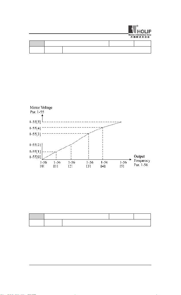
C01.55 V/F Chara cter istic - U Default setting 0V
Range [0 - 999 V]
● Fu nction: This pa ra me ter is an arr ay parame te r [0-5] and is only
functional when par. C01.01, Motor Control P rinciple is set to V/F [0].
En ter volt age at eac h fr e qu enc y poi nt to ma nu all y for m a V/F
character ist ic matching motor. Frequen cy poi nts are defin ed in pa r.
C01.56, V/F characteristics - F.
HLP-NV Series
- 43 -
Page 49
HLP-NV Series
C01.56 V/F Chara cter istic - F Default sett ing 0H Z
Range [0 - 40 0 Hz]
● Fu nc tion :Th is pa ra me te r is an ar ray para me te r [0-5] an d is on ly
functional when par. C01.01, Motor Control P rinciple is set to V/F [0].
En t er fr eq uen c y poin ts to ma nua lly for m a V/F cha rac ter ist ic
matching motor. Voltage at each point is de ned in pa r. C 01.55, V/F
Character istic - U.
Ma ke a V/F cha rac teris tic base d on 6 def in abl e volt age s a nd
frequencies, see below gure.
Simplif y V/F character istics by merging 2 or more points (voltages and
frequencies), respectively, are set equal.
● ATTENTION! For par. C01.56 the followi ng applies [0]≤ [1] ≤ [2] ≤
[3] ≤ [4] ≤ [5]
C01.6* Load Dependent setting
Parameters for adjusting the load dependent motor settings.
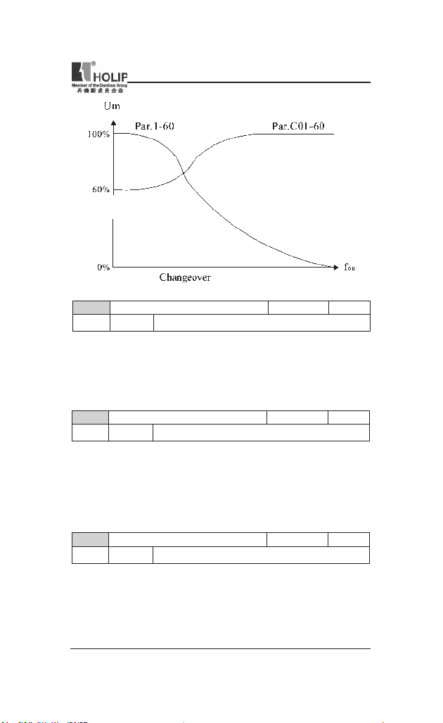
C01.60 Low Speed L oad Compensation D efault setting 100%
Range [0 -199 %]
● Fun ct ion: Use this para met er to gai n optimum V/F chara cterist ic
when running at low speed.
Enter pe rcentage in relation to load when motor run s at low speed.
Change -over poi nt is automatically calculated based on motor size.
- 44 -
HLP-NV Series
Page 50
HLP-NV Series
C01.61 High Speed Load C ompensation Default setting 100%
Range [0 - 199 %]
● Func tion:Use this parame ter to obt ain opti mum load c ompensation
when running at hig h speed.
Enter percentage to compensate in relation to load when motor runs at
high speed.
Change -over poi nt is automatically calculated based on motor size.
C01.62 Slip Compe nsation Default se tti ng 100%
Range [- 400 - 399 %]
● Fu nct ion : C om pens ati on for loa d d epe nde nt moto r sl ip. Sli p
compen sation is calculated automatically based on rate d motor s peed,
nM,N.
● ATTE N TI ON ! T his fun cti on is only act iv e whe n par . C01.0 0,
Con fi gu ration Mod e, is s et to Speed Open Loop [0],and when par.
C01.01, Motor Cont rol Principle, is set to VVC+ [1].
C01.63 Slip Compe nsation Time Con stant Default setting 0.10 s
Range [0.05 - 5.00 s]
● Funct ion: 0.10 s [0.05 - 5.00 s] Enter slip compensation reaction speed.
A high value result s in slow reaction whereas a low value r esu lts in
quick rea ction.
If low-frequency resonance problems arise, use longer time setting.
HLP-NV Series
- 45 -
Page 51
HLP-NV Series
1-7* Start Adjustments
Considering t he need for various sta rt functions in d ifferent applications,
it is possible to select a nu mber of functions in this par amete r group.
C01.71 Star t Delay Default setting 0.0S
Range [0.0 - 10.0 s]
● Func tion: The st art dela y def ine s the ti me to pas s fro m a st art
comma nd is given until t he motor starts accele rati ng.
Setting sta rt delay to 0.0 sec. disables Start Function, [C01.72], when
star t command is given.
Ente r the time delay requir ed before commencing acceleration. Par.
C01.72 Star t Function is active dur ing Start delay time .
C01.72 Star t Funct ion Default set ting 2
Range [0] DC Hold/ Dela y Time Motor is ene rgi zed with
[1] DC Brake/ Delay Time Motor is energized with
[2] Coast /Delay Time I n v er t e r i s c oa st e d
C01.73 Flying St art Default setti ng 0
Range [0] Disabled Flying star t is not re quired.
[1] Enabled F re que nc y co nv er ter e na bled to
● Funct ion: Use ying start to cat ch a spin ni ng motor afte r eg. mai ns
dropout.
● Warning: T his function is not suitable for hoisting applications.
● ATTENTION! W hen ying st art is enabled par. C01.71, Start Delay,
and par. C01.72, Star t Funct ion, have no f unct ion.
DC hold ing current ( par.
C02.0 0) du ri ng s ta rt
delay time.
DC bra king cur rent ( par.
C 0 2 .0 1) d u r in g st ar t
delay time.
du ri ng s ta rt delay ti me
(inver ter off ).
catch spi nni ng motor.
- 46 -
HLP-NV Series
Page 52

HLP-NV Series
C01.8* Stop Adjustments
To meet the need for various stop fu nctions in d ifferent appl ication these
parameters offer some special stop features for t he motor.
C01.80 Function at Stop Default setti ng 0
Range [0] Coa st The inve rter i s coast ed.
[1] DC hold T he motor is ene rgi zed with a DC
cur rent. See par. C02.0 0 DC Hold
Current for more information.
● Fun c tio n: T he sele cte d fu nct io n at st op is act ive in followi ng
situations:
■ Stop command is given and ou tput speed is ramp ed down t o Min.
Speed for Activati ng Funct ions at Stop.
■ Start command is removed (standby), and output speed is ramped
down to Min. Speed for Activating Functions at Stop.
■ DC-brake command is g iven, and DC-bra ke time has passed
■ While running a nd calculated out put speed is below Min. Speed for
Activating Functions at Stop.
C01.82 Min Speed for Func t. at Stop [ Hz] Defau lt sett ing 0.0HZ
Range [0.0 - 20.0 H z]
● F unct ion: Set the speed at which to activate par. C01.80 Function at
Stop.
C01.9* Motor Temperature
With an estimated motor temperature monitor the f reque ncy conve rter is
able to estimate mot or tempe ratu re without having a thermistor mounted.
It is thus possible to receive a war ning or an alarm, if motor temperature
exceeds upper operational limit.
HLP-NV Series
- 47 -
Page 53

HLP-NV Series
C01.90 Motor The rmal P rotec tion Default setti ng 3
Range [0] No Pr otect ion
Disa bles temp erat ure mon itoring.
[1] Ther mistor Warni ng
A therm is to r conn ec te d to eit her
wa rnin g if upp er lim it of mo to r
[2] Ther mistor Trip
A therm is to r conn ec te d to eit her
an alar m and makes the frequency
lim it of motor temperatur e range
[3] ETR Warn ing
If calcu lat ed upper lim it of mo tor
[4] ETR Trip If calcu lat ed upper l im it of motor
digital or analog input gives a
tempe ratu re ra nge is exceeded , (see
par. C01.93, Ther mistor Resour ce).
digital or analog input gives
conver ter tr ip if upp er
is exceed ed, (see pa r. C01.93,
Ther mistor Resource.
tempe ratu re r ange is exc ee ded, a
warn ing occurs.
te mpe rat ure r ang e is ex cee ded ,
an a la rm occ urs and fr equ enc y
conver ter tr ips.
● Fu nc tion : Us ing ETR (Ele c t ro nic Ter m ina l Re l ay ) th e mo tor
temperatu re is calculated based on frequency, speed and time. Danfoss
recom mends using The ETR fu nction, if a ther mistor is not present.
● ATTENTIO N! ETR c alculat ion is based on motor data from group
C01.2*.
C01.93 Ther mistor Resour ce Defau lt sett ing 0
Range [0] None
No thermis tor is con nect ed.
[1] Analog I nput VIN
Con nect thermistor to analog input
[6] Digita l Input JOG
Con nect thermis tor to digit al input
W hi le t h i s in put f u nc t ion s as
Terminal VIN.
Terminal JOG.
t he rm i s t or i np ut , i t wi l l no t
res pon d to the fu nction chos en in
pa r. C0 5.13, Di git al Inp ut JO G.
The val ue of p ar. C05.13 remains
howe ver un chang ed i n parame te r
database whi le fun ction is i nact ive.
- 48 -
HLP-NV Series
Page 54
HLP-NV Series
● Function: Select t he ther mist or input t erm inal.
● ATTE NTION! A na lo g Inp ut V IN can no t be sele cted for oth er
purposes whe n selected as thermistor resource.
Input Dig ital/Analog Supply Voltage Th reshold C ut-out Values
Digital 10 V <800 oh m - >2.9k ohm
Analog 10 V <800 ohm - >2.9k ohm
Parameter group 2: Brakes
C02.0* DC-Brake
Th e pur pose of DC -b rake fun ct io n is to br ake a r ot ati ng mo to r by
applying DC-current to the motor.
C02.00 DC Hold Cur rent Defau lt sett ing 50%
Range [0 - 100%]
● Funct ion: This par ameter eit her holds t he motor (holding torque) or
preheat s the motor.
■ The pa rameter is active if DC Hold has been selected in either par.
C01.72 Star t Function or par. C01.80 Function at Stop.
■ Ente r a value for holdi ng cu rrent as a percentage of the rated motor
current set in par. C01.24 Motor Cur rent. 100% DC holding current
corresponds to I
● ATTENTION! Avoid 100% c ur rent too long as it may overheat the
motor.
C02.01 DC Brake C urrent D efault settin g 50%
Range [0 - 100%]
● Function: Set DC-cur rent needed to brake rot ating motor.
Activate DC-brake in one of the four following ways:
■ DC-brake command, see par. C05.1* choice [5]
■ DC Cut-in f unction, see par. C02.04
■ DC-brake selected as start f unct ion, see par. C01.72
■ DC-brake in connect ion with Flying St art , par. C01.73.
C02.02 DC Brak ing Time Defa ult setting 10.0S
Range [0.0 - 60 s] S et the time DC-bra ki ng c ur rent,
● Function:DC-braking time de nes the period dur ing which DC-br ake
current is applied to the motor.
● ATTENTION! If DC-brake is activated as star t function, DC-brake
time is dened by star t delay time.
.
M,N
set in pa r. C02.01, must be applied.
HLP-NV Series
- 49 -
Page 55

HLP-NV Series
C02.04 DC Brake C ut In Speed Default set ting 0.0HZ
Range [0.0 - 40 0.0 Hz]
● Function: Set DC-brake cut-in speed t o a ctivat e DC braking cur rent,
set in par. C02.01, when rampi ng down.
When set to 0 the f unction is off.
C02.1* Brake Energy Function
Us e th e pa ram e te rs in thi s gro up for selec t ing dyn ami c bra king
parameters.
C02.10 Brake Function Default set ting 0
Range [0] Of f No brake func tion.
[1] Resisto r Brake Resistor br ake is ac tive.
[2] AC Brake AC brake is act ive.
● Function:
■ Resistor Brake:
The resistor bra ke li mit s voltage in t he inter med iate circuit when
the motor acts as generat or. Without brake resistor, t he fr equency
converter event ually trips.
The resistor brake consume s surplu s energy resulting from motor
braking. A f reque ncy convert er wit h brake stops a motor faste r
than without a brake, wh ich is u sed in many applications. Requires
connection of external brake resistor. An alte rnative to the resistor
brake is t he AC brake.
■ AC Brake:
The AC brake consumes surplus energy by cre ating power loss i n
the motor.
It is important to keep in m ind that a n inc rease in power loss causes
motor temperature t o rise.
● ATTENT ION ! Re sis to r brake is on ly funct io na l in fr eq ue nc y
converters w ith integrated dy namic brake. An ext ernal resistor must
be connected.
C02.11 Brake Resistor (ohm) Default sett ing *Ω
Range [5 - 500 0 Ω]
● Function: Set brake resistor value.
C02.16 AC Brake, Max c urr ent Default setting 100%
Range [0 - 40 0 %]
● Fun ct ion: Enter max. pe rm issible current for AC-braking to avoid
overheating of motor.
100% equals motor cu rrent set in pa r. C01.24.
- 50 -
HLP-NV Series
Page 56
HLP-NV Series
C02.17 Over-voltage Control D efault setting 0
Range [0] Disabled The OVC is not active/requ ired.
[1] Enabled , not at stop
OVC is run ning u nless a stop sign al
[2] Enabled OVC is run ni ng, also when a st op
is active.
signal i s active.
● Funct ion: Use Over-voltage Control (OVC) to reduce the risk of the
fre que ncy converter t ripping due t o an over voltage on the D C link
cau sed by ge ner at ive power from the loa d. An over-volt age occu rs
eg. if the ramp dow n time is set too shor t compared to the actual load
iner tia.
● ATT ENTIO N! If Resistor Brake ha s be en cho se n in pa r. C02.10
Bra ke Functio n th e OVC is not acti ve even th oug h enabled in this
parameter.
2-2* Mechanical Brake
For hoist ing ap pli cat ions an ele ct ro-ma gn et ic brake is requ ir ed. Th e
brake is c ontrolled by a relay, which releases t he brake when activated.
The brake act ivate s if frequency conver ter trips or a coast c ommand is
given. Fu rthermore, it act ivates when motor speed is ramped down below
the speed set in par. C02.22, Active Bra ke Speed.
C02.20 Release Br ake Current Default sett ing 0.00A
Range [0.00 - 100 A]
● Funct ion: Select motor current at which mechanical brake releases.
● Warn ing: If star t delay time has passed, and motor cu rrent is below
Release br ake current, frequency converter trips.
C02.22 Activate Brake Spe ed [Hz] D efault setting 0
Range [0 - 40 0 Hz] S el ec t m ot or s p e e d at wh ic h
ramping down.
mechanical br ake act ivates when
● Funct ion: If the motor is stop ped using ramp, the mechanical bra ke is
activated when motor speed is less than Active Brake Spe ed.
Motor is ra mped dow n to stop i n the following situations:
■ A star t command is removed (stand by)
■ A stop com mand is activated
■ Quick-stop is activated (Q-stop ramp is used)
● Mechan ical bra ke automat ically activates if frequency converter trips
or repor ts an alarm.
HLP-NV Series
- 51 -
Page 57
HLP-NV Series
Parameter group 3: Reference/Ramps
Pa ram ete r s for refe ren ce han dli ng, def init io n of li mi t at ions, a nd
cong urat ion of the frequency
converter's reaction t o changes
3-0* Reference Limits
Parameters for setti ng the refe rence u nit, limits a nd ranges.
C03.00 Reference Range Default setting 0
Range [0] Mi n - Max Reference set point ranges can h ave
Se le ct thi s i f run ning in Pr oc es s
[1] -Max-+Max Ranges can h ave both p ositive and
● Funct ion: Select t he range of reference and fee dback signals. Values
can be bot h posit ive and negative, unless par. C01.00, Congur atio n
Mode, is set to Process Closed Loo p [3]. In t hat case on ly positive
values are allowed.
C03.02 Mini mum Reference Default se tti ng 0.000
Range [- 4999.000 - 4999.000]
● Fu nc tio n: Ent er value fo r mini mum re fe ren ce . The sum of al l
inter nal a nd external refer neces are clamped (limited) to t he mi nimu m
reference value, pa r. C03.02.
C03.03 Maximum Refere nce Default setting 50.000
Range [- 4999.000 - 4999.000]
● Funct ion: Maximum Reference is adjustable in the range Minimu m
Reference- 4999.
Enter value for Maximum Reference.
The sum of all internal and exter nal references are clamped (limited)
to the ma ximum reference value, par. C03.03.
positive values on ly.
Closed Loop.
negative values.
- 52 -
HLP-NV Series
Page 58

HLP-NV Series
3-1* References
Pa ra meter s for set t in g up the refe ren ce sou rce s. Selec t the pre se t
references for the corresponding digit al inputs in par amet er group 5.1*,
Digital Inputs.
18 Bit2 17 Bit1 16 Bit0 Preset reference no.
0 0 0 0
0 0 1 1
0 1 0 2
0 1 1 3
1 0 0 4
1 0 1 5
1 1 0 6
1 1 1 7
Table 4.1: Par. C05.1* selection [16], [17] and [18]
C03.10 Preset Reference Default setting 0.00%
Range [ -100.00 - 100.0 0%]
● Funct ion: Each parameter set-up contains 8 preset references which
are selectable via 3 digita l inputs or bus.
En te r the dif fe rent prese t refer enc es using arr ay progr amm ing.
Normally, 100% = value set i n par. C03.03,
Maxi mum Reference. However, the re are exceptions if par. C03.00 is
set to Mi n - Max, [0].
Example 1: Par. C03.02 is set to 20 and par. C03.03 is set to 50. In this
case 0%= 0 and 100% = 50.
Example 2: Par. C03.02 is set to -70 and par. C03.03 is set to 50. In this
case 0% = 0 and 100% = 70.
C03.11 Jog Speed [Hz] Default setting 5.0H Z
Range [0.0 - 40 0.0 Hz] Select s peed to f unction as jog speed.
● Funct ion: Jog speed is a xed output speed a nd overr ules the selected
reference speed, see par. C05.1* selection [14].
If the motor is st opped while in jog mode, the jog signal acts as a st art
signal. Removing the jog signal makes the motor ru n accordi ng to the
selected cong urat ion.
C03.12 Catch up/slow Down Value Default s etti ng 0.00%
Range [0.00 – 100.00%]
● Funct ion: The Catch-up/Slowdown function is activated by an input
comma nd (see par. C05.1*, choice [28]/[29]). If t he com mand is active,
HLP-NV Series
- 53 -
Page 59

HLP-NV Series
the Cat ch-up/Slowdow n value (in %) is added to t he reference f unction
as follows:
Reference = Reference + reference × Catchup Slowdown /100
Reference = Reference - reference × Catchup Slowdown /100
When the input com mand is inactivate d, the refere nce retur ns to it s
origi nal value ie. Reference = Reference + 0.
C03.14 Preset Relative Reference Default setting 0.00 %
Range [-100.00 - 100.00%]
● Funct ion: Def ine fixed value in % t o be added to variable value
dened in par. C03.18, Relative Scal ing Reference Source. The sum of
xed and va riable values (labelled Y in illust ration below) is multiplied
with actual reference (labelled X in illustation). T his product is added
to actual reference X + X *Y /100
C03.15 Reference Resour ce 1 Defau lt sett ing 1
Range [0] No Function No reference sig nal is dened.
[1] Analog Input V IN
Use sig nals from ana log I nput V IN
[2] Analog Input A IN
Use sig nals from ana log I nput A IN
[8] Puls e input Use si gn als fro m pul se inp ut as
[11] Local Bus Ref.
Us e si g n a l s f r om lo ca l bu s a s
[21] LCP Potentio meter
U s e s i g n a l s f r o m L C P
as reference, see par. C06.1*.
as reference, see par. C06.2*.
referen ce, see pa r. C05.5*.
referen ce, see pa r. C08.9*.
potent iomete r as reference, s ee pa r.
C06.8*.
● Funct ion: Par. C03.15, C03.16 and C03.17 dene up to three different
reference signa ls. The sum of t hese reference signals denes the actual
reference.
- 54 -
HLP-NV Series
Page 60

HLP-NV Series
C03.16 Reference Resour ce 2 Default set ting 2
Range [0] No Function
No reference signal is den ed.
[1] Analog Input V IN
Use sig nals from ana log I nput V IN
[2] Analog Input A IN
Use sig nals from ana log I nput A IN
[11] Local Bus Ref.
Us e si g n a l s f r om lo ca l bu s a s
[21] LCP Potentio meter
U s e s i g n a l s f r o m L C P
as reference.
as reference.
referen ce.
potent iomete r as reference.
● Funct ion: See Par. C03.15 for description.
C03.17 Reference Resour ce 3 Default setting 11
Range [0] No Function
No reference signal is den ed.
[1] Analog Input V IN
Use sig nals from ana log I nput V IN
[2] Analog Input A IN
Use sig nals from ana log I nput A IN
[11] Local Bus Ref.
Us e si g n a l s f r om lo ca l bu s a s
[21] LCP Potentio meter
U s e s i g n a l s f r o m L C P
as reference.
as reference.
referen ce.
potent iomete r as reference.
● Funct ion: See Par. C03.15 for description.
HLP-NV Series
- 55 -
Page 61

HLP-NV Series
C03.18 Relative Scaling Ref. Resour ce Default setting 0
Range [0] No Function
The function is disabled
[1] Analog Input V IN
Select analog In put V IN as r elative
[2] Analog Input 54
Select a nalog inpu t 54 as rel ative
[8] Puls e Input 33
Sele ct pu ls e inp ut 33 as rel at ive
[11] Local Bus Ref.
Se le ct loc al bus ref . as rel at ive
[21] LCP Potentio meter
S e l e c t LC P p o t en ti om et er a s
scali ng refere nce source.
scali ng refere nce source.
scali ng refere nce source.
scali ng refere nce source.
relative s caling referen ce source.
● Func tion: Select the s ource for a var iable value to be added to th e
xed value dened i n par. C03.14, Preset Relative Reference.
3-4* Ramp 1
A l inear ramp i s characterized by ramping up at a cons tant speed until
the de si re d moto r spee d has bee n reac hed. Some ove rsho ot may be
experienced whe n reaching speed , which may c ause spe ed jerks for a
short wh ile before stabilizing.
An S -ramp accele rates more smoothly thus compensating for jerks when
the speed is reached.
See the below gure for a compar ison of the two ramp types.
- 56 -
HLP-NV Series
Page 62

HLP-NV Series
Ramp Times:
Ramp up: Acceleratio n time. From 0 to nom inal motor frequency (par.
C01.23).
Ram p dow n: Decele ration time. From nom inal motor frequency (par.
C01.23) to 0.
Limitation:
Too short ramp up time can resu lt in Torque l imit war ning (W12) and/or
DC over voltage warning (W7). Rampi ng is stopped when the frequency
converter has reached Torque limit mot or mode ( par. C04.16).
Too short r am p dow n time can re sult in Torque li mit war ning (W12)
and /or DC over voltage war ni ng (W7). Rampi ng is s top ped when the
fr eq ue nc y conver te r rea ches the Torq ue li mi t gene ra to r mode (pa r.
C04.17) and/or the i nter nal DC over volt age limit.
C03.40 Ramp 1 Type Default se tting 0
Range 0 Linear Consta nt accele ration /deceler ation.
2 S-r amp Smooth je rk compe nsate d
C03.41 Ramp 1 Ra mp up Time Default s etti ng 3.00/
15.00S*
Range [0.05 - 360 0 s ]
● Funct ion: Enter ramp-up time f rom 0 Hz to rated motor speed (nM,N)
set in par. C01.25.
Choose a ramp-up t ime ensuring that output curr ent does not exceed
current limit set in par. C04.18 during rampi ng.
* only for NV4,NV5
acceleration /deceleration.
C03.42 Ramp 1 Ra mp Down Ti me Default setti ng 3.00
/30.0 0S*
Range [0.05 - 360 0 s]
● Function: Enter r amp down t ime from rate d motor speed nM,N in
par. C01.25 to 0 Hz.
Choose a r amp down time that does not cause over-voltage in inver ter
due to rege nerat ive operation of motor. Furthermore, generated current
must not exce ed cur rent limit set in par. C04.18.
* only for NV4,NV5
HLP-NV Series
- 57 -
Page 63

HLP-NV Series
C03.5* Ramp2
See par. C03.4* for a descript ion of ramp t ype s.
ATTENTION! Ramp2 - alter native ramp time s: Cha nging from Ramp1
to Ramp2 is done via the digital input. See par. C05.1*, selection[34].
C03.50 Ramp 2 Type Default setti ng 0
Range [0] Linear Consta nt accele ration/decele ration.
[2] S-ramp S mo o t h je r k c om p e n s a t e d
C03.51 Ramp 2 Ra mp up Time Default setting 3.00/
15.00S*
Range [0.05 - 360 0 s]
acceleration /deceleration.
● Function: Enter ra mp-up time from 0 Hz to rated motor speed (nM,N)
set in par. C01.25.
Choose a ramp-up time ensuring that output current does not exceed
current limit set in par. C04.18 during rampi ng.
* only for NV4,NV5
C03.52 Ramp 2 Ramp down Time Default setting 3.00/
30.00S*
Range [0.05 - 360 0 s]
● Funct ion: Ente r ramp down ti me from rated motor speed nM ,N in par.
C01.25 to 0 Hz.
Choose a r amp down time that does not cause over-voltage in inver ter
due to rege nerat ive operation of motor. Furthermore, generated current
must not exce ed cur rent limit set in par. C04.18.
* only for NV4,NV5
C03.8* Other Ramps
This section contains para meter s for Jog and Quick Stop Ramp
With a Jog R amp you can both ramp up and down whereas you can only
ramp dow n with the Quick Stop Ramp.
C03.80 Jog Ramp Time Default setting 3.00/
15.00S*
Range [0.05 - 360 0 s]
● Func tion: A linear ramp applic able when Jog is activate d. See p ar.
C05.1*, selection [14].
Ramp up t ime = Ra mp down time.
Jog Ramp time star ts u pon act ivat ion of a jog signal via a sele cted
digital input or serial communication port.
* only for NV4,NV5
- 58 -
HLP-NV Series
Page 64

HLP-NV Series
C03.81 Quick Sto p Ramp Time Default s etti ng 3.00/
30.0 0S*
Range [0.05 - 360 0 s]
● Funct ion: A linear ramp applicable when Q-stop is activated. See par.
C05.1*, selection [4].
* only for NV4,NV5
Parameter group 4: Motor Limits
Parameter group for con gur ing li mits a nd warning.
C04.1* Motor Limits
Use these parameters for dening the speed, torque and current working
range for t he motor.
C04.10 Motor Spee d Dire ction Default setti ng 2
Range [0] Clockwise Th e m ot or s h a f t r o ta te s in
preve nts the moto r fro m ru nni ng in
If par. C01.00 C ong ur ation mode
[1] Counterclock wise
T h e mo t or s h a f t r o ta te s in
se tti ng prevent s the moto r f rom
[2] Both With this setting t he motor can r un
th e out put freq uen cy is l imited to
Limit (par. C04.12) to Motor Speed
● Func tion: I f ter minals 96, 97 and 98 a re connected to U, V and W
respectively, the motor runs clockw ise when seen from the front.
● ATT ENTION! This paramete r cannot be adjusted while the motor is
run ning
C04.12 Motor Spee d Low Limit [Hz] Default set ting 0.0 HZ
Range [0.0 - 40 0.0 Hz]
● Funct ion: Set the Mi nimu m Motor Speed Lim it cor resp onding to the
minimum out put frequency of the motor shaft.
● ATT EN TION! As the min imum ou tput frequenc y is an ab solut e
value, it ca nnot be deviated from.
HLP-NV Series
clockwise dir ection. This s etti ng
counterclock wise di rect ion.
ha s bee n se t to Pr oc ess Clo sed
L o op [3 ] th is pa ra me t e r mu st
always be set to Clock wise
counterclock wise di rect ion. Th is
run ning in clockwise di rection.
in both d irec tions. However,
the range: Motor Spe ed Low
High Limit (pa r. C04.14).
- 59 -
Page 65

HLP-NV Series
C04.14 Motor Spee d High Li mit [Hz] Def ault set ting 65.0H Z
Range [0.0 - 40 0.0 Hz]
● Fu nc ti on: Set the Max im um Motor Spee d corre sp on di ng to th e
maximum out put frequency of the motor shaft.
● ATT EN TIO N! As the maxi mum output freq uency is an abs olute
value, it ca nnot be deviated from.
C04.16 Torque Limit Motor Mode Defau lt sett ing 150%
Range [0 - 40 0%]
● Funct ion: Set the torque limit for motor oper ation.
The set ting is not automatically reset to default when changi ng sett ings
in par. C01.00 to C01.25 Load & Motor .
C04.17 Torque Limit Ge nerat or Mode Default setti ng 100%
Range [0 - 40 0 %]
● Funct ion: Set the torque limit for generator mode ope ration.
The set ting is not automatically reset to default when changi ng sett ings
in par. C01.00 to C01.25 Load & Motor.
C04.5* Adjustable Warnings
Parameter g roup containing a djustable war ning limits for current, sp eed,
reference and feedback.
Warnings are show n in display, progra mmed output or serial bus.
C04.50 Warning Cur rent Low Defau lt sett ing 0.00A
Range [0.00 - 26.00 A]
● Funct io n: Use th is parame te r to set a lower lim it for th e cu r rent
range. If current drops below the set limit, a war ning occurs.
C04.51 Warning Cur rent Hig h Defau lt sett ing26.00A
Range [0.00 - 100.00 A]
● Function: Use this parameter to se t an upper lim it for t he current
range. If current exceeds the set limit , a warning occurs.
C04.58 Missing Motor Phase Funct ion Default setting 1
Range [0] Of f Funct ion is disabled.
[1] On Func tion is en abled.
- 60 -
HLP-NV Series
Page 66

HLP-NV Series
● Functi on: A mi ssi ng motor phase causes the m otor torque to d rop.
This monitor may be disabled for special purposes (eg. small motors
run ning pure V/F mode), but as there is a risk of overheating the motor,
Danfoss strongly recom mends that the function is On.
A mis sin g motor phases cau ses t he frequ enc y conver ter to trip and
repor t an ala rm.
● ATTENTION! This parameter can not be changed while motor r uns.
C04.6* Speed Bypass
In some applications mechan ical resonance may o ccur. Avoid reson ance
points by creating a bypass. The frequency conver ter ramps th rough the
bypass area thereby pa ssing mechanical resonance points quickly.
C04.61 Bypass Speed From [Hz] Default set ting 0.0H z
Range [0.0 - 40 0.0 Hz]
● Funct ion: Ar ray [2]
Ente r eit her the lower o r upp er limit of the spe eds t o be avoided. It
does not matter whethe r Bypass From or Bypass Too is the upper or
lower l imit, however the Spe ed Bypass function is disabled if the two
parameters are set to the same value.
C04.63 Bypass Speed To [Hz] Default setting 0.0H z
Range [0.0 - 40 0.0 Hz]
● Funct ion: Ar ray [2]
Enter eit her the upper or lower limit of the speed area to be avoided.
Mak e su re t o enter the opp osite limi t of that in par. C0 4.61 Speed
Bypass From [Hz].
Parameter group 5: Digital In/Out
The following describes all digital input command fu nction s and signals.
C05.1* Digital Inputs
Parameters for conguri ng the functions for the i nput terminals.
Th e dig ital inp ut s a re use d for sel ect ing va rious f unc tions i n the
frequency conve rter. All digit al inputs can be set to the following:
HLP-NV Series
- 61 -
Page 67

HLP-NV Series
C05.10 Term inal RU N Digita l Input Default setting 8
C05.11 Term inal F/R Digital Input Default sett ing 10
C05.12 Term inal RST Digital Input Default setti ng 1
C05.13 Term inal JOG Digital Input Default setti ng 14
C05.15 Term inal EMS Digita l Input Default se tti ng 16
Range See the follow ing table
[0] No Operation T he freq uen cy con ver ter will not
re ac t t o sig n al s tr an smit ted to the
terminal.
[1] Reset Re set the fr eq uency conve rter af ter
a Trip /Alarm. Not all alarms can be
reset.
[2 ] Coast Inverse Coas ti ng stop, inver te d input (N C).
The freq ue ncy convert er leaves the
motor in f ree mode.
[3] Coast and reset inv. Re set and coasting stop inverted input
(NC). The frequency converter resets
and leaves t he motor i n free mode.
[4] Quick stop inverse Inverted i nput ( NC). Generates a stop
in a cc ord anc e wit h the quick- sto p
ramp time set in par. C03.81. Whe n
motor stops, shaf t is in f ree mode.
[5] DC-brake inv. I nver ted input for DC braki ng (NC).
Stops motor by ene rgizing it with DC
cur rent for a certain t ime period, see
par. C02.01. Funct ion is onl y ac tive
when value in par. C02.02 is different
from 0.
[6] Stop inv. St op i nver ted f unc ti on. Ge ner at es
stop function when select ed ter minal
goes fr om lo gi ca l leve l “1” to “0 ”.
St op is p er fo r me d ac co r d i n g to
selected ramp time.
[8] Start Select start for a start/stop command.
1 = Star t, 0 = stop.
[9] Latched st art Motor starts i f a pul se is applied fo r
mi n. 2 ms. Motor sto ps when Stop
inverse is activated.
[10] Reversing Chang e d i r e ctio n of mo tor s haft
rot a t i o n . Re v e r s i ng si g n a l on ly
- 62 -
HLP-NV Series
Page 68

HLP-NV Series
changes direction of rotat ion; it does
no t acti va t e sta rt fu nct ion . Sel ec t
0 = normal, 1 = reversing.
[11] Start reversing Use for star t/stop and for reversi ng at
0 = stop, 1 = sta rt reve rsing.
[12] Enable star t forwa rd Us e i f mo to r sh af t m u s t rot a t e
[13] Enable start reverse Us e if m o t o r sh af t mu s t ro ta te
[14] Jog Use for activating jog speed. See par. C03.11.
[16] Preset ref bit 0 Pr e se t ref bi t 0, 1 a nd 2 ena bles a
[17] Preset ref bit 1 Same as preset ref bit 0 [16], see par.
[18] Preset ref bit 2 Same as preset ref bit 0 [16].
[19] Freeze reference Fre eze actu al refer enc e. The froz en
[20] Freeze out put Fr eez e the act u al mo to r fre qu en cy
AT TE NTI ON! W hen free z e outpu t is a ct ive , th e fr equ e nc y
converter can not be stopped via a low Star t [8] signal.
Stop the frequency converter via a termi nal programmed for Coasting
Inverse [2] or Coast and reset, i nverse [3].
Both di rections [2] in par. 4.10.
the sa me time. Signals on star t [8] are
not allowed at the same t ime.
clockwise at sta rt.
counterclockwise at st art.
choice bet ween one of the eight preset
re fer enc e s ac c or ding to th e ta bl e
below.
C03.10.
reference is now the p oint of enable/
co nd iti on fo r Spe ed up and Sp eed
dow n to be used. If Spee d up/dow n
is used, speed change always follows
ra mp 2 (p ar. C 03 .51 an d C03 .5 2)
in the range par. C03.02 Mi nimum
Ref er en ce - par. C03.03 Ma ximu m
Reference.
(Hz). The frozen motor freque ncy is
now the point of enable/condition for
Speed up and Speed down to be used.
If Speed up/down is used , the speed
change always fol lows ramp 2 in the
range par. C04.12, Mot or Speed Low
Li m it - pa r. C04 .14, Mot or Spe ed
High Limit
HLP-NV Series
- 63 -
Page 69

HLP-NV Series
[21] Speed up S elect Sp ee d up an d Spee d down if
Wh en Spee d u p is act ivat ed fo r les s tha n 400 ms. the res ul tin g
[22] Speed down Same as Speed up [21].
[23] Setup select bit 0 Set pa r. C0 0.10 Active set-up to Multi
[26] Precise stop inverse P rol o ng th e s top s ignal t o g ive a
[27] Star t, precise stop A s [26], but including St art.
[28] Catch up Select Catch up/Slow down to i ncrease
[29] Slow down Sa me as Catch up [28]
[32] Pulse input (only Terminal EMS)
S ele ct Pu ls e in p u t when usi ng a
[34] Ramp bit 0 Logic 0 = Ramp1, see par. C03.4*.
Log ic 1 = Ramp2, see par. C03.5*.
[60] Counter A(up) Input for counter A.
[61] Counter A(down) Input for counter A.
[62] Reset counte r A Input for reset of counter A.
[63] Counter B(up) Input for counter B.
[64] Counter B(down) Input for counter B.
[65] Reset counter B Input for reset of counter B.
dig ital co ntrol of t he up/down speed
is d e sire d (m oto r p ote nt io met er) .
Acti va te thi s fu nc tion by se le ct ing
ei t h er Free ze re fer enc e o r Fr eez e
output.
refe rence will be inc rease d by 0.1%.
If Speed up is activated for more than
400 ms . the resulti ng referenc e will
ra mp ac c or di ng to ra mp 2 in pa r.
C03.51.
set-up. Log ic 0 = set-up 1, Logic 1 =
Set-up 2.
precise stop independent of scan time.
The function is available for Terminal
EMS only.
or reduce the resulting reference value
by the percentage set in pa r. C03.12.
puls e seq uence as either reference or
feedback. Scali ng is done in par. group
C05.5*.
C05.4* Relays
Parameter group for con gur ing timing and output functions for relays.
C05.40 Function Relay Default setting 9
Range See the follow ing table
- 64 -
HLP-NV Series
Page 70

HLP-NV Series
[0] No Operation Def au lt for all di g i t a l an d re l a y
[1] Control Ready Control board receives supply volt age.
[2] Drive Ready Fr e que ncy co n ve rt e r i s re ad y fo r
[3] Drive Ready, Remote Fr eque ncy co nve r ter is re a dy fo r
[4] Enable/No War ning Fr e q uen cy co nve rt e r is r e a dy fo r
No warnings are present.
[5] Drive Run ning Motor is run ning.
[6] Running/ No Warning M otor r u n s, an d no wa r n in g ar e
[7] Run in Range/ No Warning
M ot o r ru n s wi th in prog r a mm ed
[8] Run on ref/ No Warn ing Motor r uns at reference speed.
[9] Alarm A n alar m activates out put.
[10] Alarm on Warn ing An alar m or war ning a ctivates output.
[12] Out of Current R ange Motor cur rent is out side range
[13] Below Current, low Motor cur rent is lower t han set in par.
[14] Above Current , high Mot or cur rent is highe r than set in par.
[21] Ther mal Warning Th e r mal war ni ng is pr es ent whe n
[22] Ready, No Ther mal Warning
F req ue ncy co nv er t er is re a dy fo r
[23] Remote Ready, No Thermal Warni ng
F req ue ncy co nv er t er is re a dy fo r
[24] Ready, Voltage OK Fr eq uen cy co nve rt e r is re a dy fo r
output s.
operation a nd applies supply sig nal on
control board.
operation in Auto On-mode.
operation. No st ar t or stop com mand
is given.
present.
current r anges, see parameters C04.50
and C04.51. No warnings are present.
set in paramet ers C04.50 and C04.51.
C04.50.
C04.51.
tempe ra tu re exc eeds lim it in mot or,
freq uency converte r, brake resistor or
ther mistor.
op er atio n and no ov er-t em per atu re
warn ing is present.
operation in Auto mode, and no overtemperatu re war ning is present.
operation and mains voltage is with in
HLP-NV Series
- 65 -
Page 71

HLP-NV Series
[25] Reverse Mot or runs/is ready t o ru n clockw ise
[26] Bus OK Act ive com municat ion (no time -out)
[28] Brake, No War n Br ake is active, and no warn ings are
[29] Brake Ready/No Fault Br ak e is rea dy for oper at ion , and no
[30] Brake Fault (IGBT ) Pro te cts fr eq uency conver te r if fau lt
[32] Mech. Brake Control Enables control of exter nal mechanical
[36] Control Word Bit 11 Bit 11 in control word controls relay.
[51] Local Ref Active
[52] Remote Ref Active
[53] No Alarm
[54] Start Cmd Active
[55] Running Reverse
specied voltage range.
when logic = 0 and counter clockwise
when logic = 1. Output changes as soon
as reversing sign al is applied.
via ser ial com munication port.
present.
faults a re present.
on br ake modules is present. Use relay
to cut out main voltage f rom frequency
converter.
brake, see parameter group C02.2*.
5-5* Pulse Input
Set par. C05.15 to choice [32] pu lse input. Now Terminal EMS handles
a pul se input in the ra nge fro m Low frequ enc y, par. C05. 55, to High
frequency, par. C05.56. Scale frequency input via par. C05.57 and par.
C05.58.
C05.55 Termina l EMS Low Freq uency Default sett ing 20
Range [20 - 49 99 Hz]
● Funct ion: En te r low freq ue ncy co rr es po nding to low moto r sh af t
speed (i.e. low reference value) in par. C05.57.
C05.56 Termina l EMS High Frequenc y Default setti ng 500 0
Range [21 - 500 0 Hz]
● Functi on: Enter high frequency cor respondi ng to h igh motor shaft
speed (i.e. high reference value) in par. C05.58.
- 66 -
HLP-NV Series
Page 72

HLP-NV Series
C05.57 Term. EMS Low Ref./Feedb. Value Default setting 0.000
Range [- 4999.000 - 4999.000]
● Function: Set referenc e/feedback value cor responding to low pu lse
frequency value set in pa r. C05.55.
C05.58 Term. EMS High Ref./ Feedb. Value Defa ult setting 50.0 00
Range [- 4999.000 - 4999.000]
● Func tion: Set reference/feedback value correspond ing to high pulse
frequency value set in pa r. C05.56.
Parameter group 6: Analog In/Out
Parameter group for con gur ing analog inputs and out puts.
C06.0* Analog I/O Mode
Parameter group for set ting up the analog I/O con guration.
C06.00 Live Z ero Time out Time D efault setting 10s
Range [1 - 99 s]
● Func tio n: The Live Zero function is used for mon itoring the signal
on an analog input. If th e sign al disapp ear s, a Live Zero war ni ng is
repor ted.
Set delay ti me before Live Zer o Tim eout Fun ction is ap plied (par.
C06.01).
If t he signal reappear s during the set delay, timer will be reset. W hen
live zero is detected, the frequency converter f reezes output frequency
and sta rts Live Zero Time out timer.
HLP-NV Series
- 67 -
Page 73

HLP-NV Series
C06.01 Live Zero Tim eout Function D efault setting 0
Range [0] Off Func tion is di sabled.
[1] Freeze output
Output frequenc y r emai ns at value
[2] Stop F r eq u en c y c on ve rt e r r a m ps
[3] Jogging Frequ enc y conv er ter r am ps to jo g
[4] Max Spe ed Fr eq u e nc y co nve rt er ra m ps to
[5] Stop and Trip
Fre que ncy con ver ter ra mps dow n
it had when live zero was detected.
dow n t o 0 H z. Re mov e live ze ro
er ror cond itio n befor e r es ta rti ng
frequency converte r.
speed , see par. C03.41.
Moto r Spe ed High Limit , see p ar.
C04.14.
to 0 H z and then trip s. Remove live
ze ro condit ion and activa te reset
be fo re res tart ing the f req ue ncy
conver ter.
● Funct ion: Funct ion is activated if input signal is below 50% of value
set in paramet ers C06.10, C06.12 or C06.22.
C06.1* Analog Input 1
Parameters for conguri ng scaling and limit s for analog input 1 (Terminal
VIN ).
ATTENTION!
Mic ro switch XX X in position U: Param ete rs C06.10 a nd C06.11 are
active.
Micro sw itch in position I: Parameters C06.12 and C06.13 are active.
- 68 -
HLP-NV Series
Page 74

HLP-NV Series
C06.10 Termina l VIN L ow Voltage Default setti ng 0.07V
Range [0.00 - 9.99V] Enter low volt age value.
● Funct ion: This scaling value shou ld correspond t o minimum refe rence
value set i n par. C06.14. See also section Reference Ha ndli ng.
C06.11 Termina l VIN H igh Voltage Default sett ing 10.00V
Range [0.10 - 10.00 V] Ente r high voltage value.
● Fu nct ion : Th i s sc al ing val ue sho uld cor res pon d to max imu m
reference value set i n par. C06.15.
C06.12 Termina l VIN L ow Cur rent Default setting 0.14
Range [0.00 - 19.99 mA] Enter low current value.
● Fu nc tion: Thi s refe rence sign al sh ou ld co r re sp on d to min imu m
reference value set i n par. C03.02.
● Warning: The value must be set to min. 2 mA in order to activate the
Live Zero Timeout fu nction in par. C06.01.
C06.13 Termina l VIN H igh Current D efault setting 20.00
Range [0.10 - 20.00 mA] Ent er high curr ent value.
● Func tion: This reference signal should cor res pond to the max imu m
reference value set i n par. C06.15.
C06.14 Term. VIN Low Ref./ Feedb. Value Default s etti ng 0.000
Range [- 4999.000 - 4999.000]
Enter analog i nput scaling value.
● Fun ction: The scalin g value corresp ond ing to the low voltag e/low
current set i n parameters C06.10 and C06.12.
C06.15 Term. VIN High Ref./Feedb. Value Default se tti ng 50.000
Range [- 4999.000 - 4999.000]
Enter analog i nput scaling value.
● Funct ion: The scaling value cor responding to the maxi mum reference
feedback value set i n para meters C06.11 and C06.13.
HLP-NV Series
- 69 -
Page 75

HLP-NV Series
C06.16 Termina l VIN Filter Time Consta nt Default sett ing 0.01s
Range [0.01 - 10.00 s] Enter t ime con stant .
● Fu nc tion: A fi rst- or der dig it al low pas s fil te r tim e con st ant for
suppres sing electrical noise in Ter mi nal VIN. A high ti me consta nt
value improves dampening but also increa ses time d elay through t he
lter.
● ATTE NTI ON! Thi s para met er can no t be adj ust wh ile mo to r is
run ning.
C06.19 Termina l VIN mode Default setting 0
Range [0] [0] * Voltage Mode
[1] [1] Current Mode
● Funct ion: Select t he input to be present on Termi nal VI N.
● Warning: Par. C06.19 MUST be set according to Micro sw itch XX X
setting.
C06.2* Analog Input 2
Pa ra meter s for con fig u rin g sca li ng and li mits for ana lo g inp ut 2,
Terminal AIN.
C06.22 Termina l AIN L ow Cur rent Default se tti ng 0.14
Range [0.00 - 19.99 mA] Enter low current value.
● Fu nc tion: Thi s refe rence sign al sh ou ld co r re sp on d to min imu m
reference value set i n par. C03.02.
● Warini ng: The value must be set to m in. 2 m A in order to activate t he
Live Zero Timeout fu nction in par. C06.01.
C06.23 Termina l AIN H igh Current Defau lt sett ing 20.00
Range [0.10 - 20.00 mA] Ent er high curr ent value.
● Funct ion: This reference signal should correspond to the high cur rent
value set i n par. C06.25.
C06.24 Term. AIN Low Ref./ Feedb. Value Default s etti ng 0.000
Range [-4999.000 -4999.000]
● Fu nc ti on : The scali ng value should co r re sp on d to the min imu m
reference feedba ck value set in par. C03.02.
C06.25 Term. AIN High Ref./Feedb. Value Default se tti ng 50.000
Range [- 4999.000 - 4999.000]
● Fu ncti on: The scal ing valu e shou ld cor re sp on d to th e maximum
reference feedba ck value set in par. C03.03.
Enter analog input scali ng value.
Enter analog input scali ng value.
- 70 -
HLP-NV Series
Page 76

HLP-NV Series
C06.26 Termina l AIN Filter Time Consta nt Default sett ing 0.01s
Range [0.01 - 10.00 s] Enter t ime con stant .
● Fu nc tion: A fi rst- or der dig it al low pas s fil te r tim e con st ant for
suppressing electr ical noise in term inal 54. A high ti me constant value
improves dampening, but also increases time delay through the lter.
● ATTENTION! This parameter cannot be changed while motor r uns.
C06.8* LCP Potmeter
The LC P potmet er ca n be sel ec te d either as Refer ence Reso urce or
Relative Reference Resource.
ATT EN TI ON! In Ha nd mode the LCP pot meter f un ct io ns as loc al
reference.
C06.81 LCP potm . Low Ref./ Feedb. Value Default set ting 0.0 00
R ange [- 4999.000 - 4999.000]
● Funct ion: The scaling value cor responding to 0.
Ent er lo w reference value. The refe re nce valu e cor re sp on di ng to
potent iometer tur ned fully cou nterclockwise (0 degrees).
C06.82 LCP potm . High Ref./Feedb. Value Default setting 50.000
R ange [- 4999.000 - 4999.000]
● Funct ion: The scaling value cor responding to the maxi mum reference
feedback value set i n par. C03.03.
Ent er high reference value . The reference value cor resp ondi ng to
potent iometer tur ned fully clock wise (200 degrees).
C06.9* Analog Output
These parameters are for cong uri ng the analog outputs of the f requency
converter.
C06.90 Termina l AON Mode D efault setting 0
Range [0] 0 - 20 m A Range for an alog outp ut s is 0-2 0
[1] 4-20 mA R ange fo r analog outputs is 4 - 20
[2] Digita l Fun cti ons as slow reactin g dig ita l
mA (off ) o r 20 mA (on), see par.
mA
mA
output . Set value t o either 0
C06.92.
HLP-NV Series
- 71 -
Page 77

HLP-NV Series
C06.91 Termina l AON Analog Output Default setting 10
Range [0] No Operat ion
[10] Output Frequency
[11] Referen ce
[12] Feedback
[13] Moto r Cur rent
[16] Power
[20] Spe ed
● Funct ion: Select t he function for Terminal AON as an analog output.
C06.92 Termina l AON Digital O utput Default se tting 0
Range See par. C05.4*,
● Funct ion: See pa r. C05.4*,Relays, for choices and descriptions.
C06.93 Termina l AON Output M in Scale Default setting 0.00%
Range [0.00 - 200.00%]
● Funct ion: Scale m inimum out put of selected analog signal at Terminal
AON as percentage of maximum signal value. E.g. if 0 mA (or 0 Hz)
is desired at 25% of maximum output value, prog ramme 25%. Scali ng
values up to 100% can never be higher than corresp onding setting in
par. C06.52.
C06.94 Terminal AON Out put Max Scale Default sett ing 100.00%
Range [0.00 – 200.00%]
● Fu nct ion : Scal e ma xim u m outp ut of selec t ed ana log sig nal at
Terminal AON. Set value to maximum value of current signal output.
Scale output to give a c ur rent lower than 20 mA at full sca le; or 20
mA at an outp ut below 100% of maxi mu m signa l va lue. If 20 mA
is the desired output c ur rent at a value bet ween 0 -100% of the fullscale output, programme per cent age value i n the par amet er, i.e. 50%
= 20 mA. I f a cur rent b etween 4 and 20 mA i s desi red at ma ximum
output (100%), calculate percentage va lue as follows: 20 mA/desired
maximum current × 100 %
i.e. 10 mA = 20/10 × 100 = 200%
- 72 -
HLP-NV Series
Page 78

HLP-NV Series
Parameter group 7: Controllers
Parameters g roup for congu ring applicat ion controls.
C07.2* Process Ctrl. Feedb
Select feedback sou rces and handling for Process PI Control.
C07.20 Process CL Feedba ck 1 Resou rce Default set ting 0
Range [0] No Function
[1] Analog Input V IN
[2] Analog Input A IN
[8] Puls e Input 33
[11] Local Bus Ref.
● Funct ion: Select i nput to f unct ion as feedback signal.
C07.3* Process PI Control
C07.30 Process PI Norma l/ Inve rse Ctrl Default set ting 0
Range [0] Nor mal Feedback larger than setpoi nt result
Fee dba ck les s than setpoint result
[1] Invers e Feedback lar ger tha n setpoint result
Fee dba ck les s than setpoint result
HLP-NV Series
in a speed reduc tion.
in a speed increase.
in a speed increase.
in a speed reduc tion.
- 73 -
Page 79

HLP-NV Series
C07.31 Process PI Anti Wi ndup Default set ting 1
Range [0] Disable Reg ul at ion of a g iven er ror will
f re que ncy ca nno t be inc rea sed /
[1] Enable P I - c o n t r ol l e r c e a s es f r o m
C07.32 Process PI Star t Speed Default se tti ng 0.0
Range [0.0 - 20 0.0 Hz]
conti nue even whe n the out put
decre ased.
re gu la ti ng a g iven e rr or whe n
th e ou t pu t fr equ enc y ca n no t be
incre ased /decrea sed.
● Function: Until the set motor speed has been r eached the frequen cy
converter operates i n Open L oop mode.
C07.33 Process PI Proportion al Gain Defau lt sett ing 0.01
Range [ 0.0 0 - 10.00]
● Fu nct ion: Ent er the val ue for th e P pro por tio na l ga in, i.e. the
mu lt iplic at io n f act or of th e er ro r b etw ee n t he set po i nt and th e
feedback signal.
● NOTE: 0.00 = Of f.
C07.34 Process PI Integ ral Time Default set ting 9999.00s
Range [0.01 - 9999.00 s]
● Function: The integ rat or provides an inc rea sing gain at a const ant
error between the set point and the feedback signal. The integral time
is the time nee de d by the int eg ra tor to reac h th e same gain as the
propor tional gain.
C07.38 Process PI Feed Forwa rd Factor Default set ting 0%
Range [0 - 40 0%]
● Func tion: T he FF factor sends a par t of the reference signa l arou nd
the PI cont roller which then only affects par t of the control signal. By
activating the FF factor less overshoot and high dy namics are gai ned
when changing the setpoint. Th is par ameter is always act ive when par.
C01.00 Conguration Mode is set t o Process [3].
C07.39 On Reference Bandwidth Default setti ng 5%
Range [0 - 20 0% ]
● Funct ion: Enter the value for the On Reference Bandwidth.
The PI control error is the d iffe rence betwe en set point and feedback
and wh en th is is less tha n the valu e set i n this pa ra me te r the On
Reference is active.
- 74 -
HLP-NV Series
Page 80
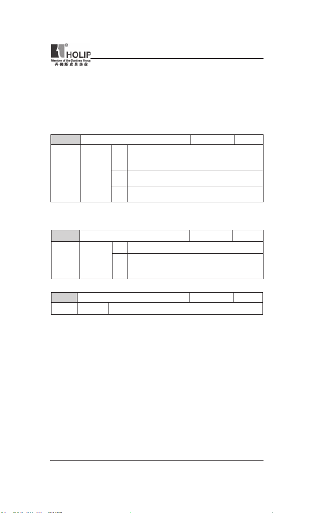
HLP-NV Series
Parameter group 8: Communication
Parameter group for con gur ing commun ication.
8-0* General Settings
Use thi s par amete r grou p for con fig u rin g the ge ner al set ti ngs for
commu nication.
C08.01 Control Sit e Defa ult setting 0
Range [0] Dig ital an d Control Word
Use both digital in put and cont rol
[1] Digita l Only
Use dig ital in put as control.
[2] Control Word Only
Use cont rol word on ly as cont rol.
● Fun ct ion: The set ti ng in thi s pa ra met er overr ul es setting s in par.
C08.50 to C08.56.
C08.02 Control Word Source Default sett ing 1
Range [0] None Func tion is inactive
[1] FC RS485 Monitorin g cont rol word s our ce is
C08.03 Control Word Ti meout Time D efault se tting 1.0S
Range [0.1 - 6500.0 s]
● Func tion: Ente r time to pass before control wo rd ti meout fu nct ion
(par. C08.04) must be carr ied out.
word as cont rol.
done via ser ial commun ication port
RS485.
HLP-NV Series
- 75 -
Page 81

HLP-NV Series
C08.04 Control Word Ti meout Function Defau lt sett ing 0
Range [0] Of f No f unct ion.
[1] Freeze Output
Freez e ou tput until commu nicat ion
[2] Stop St o p w i t h a u to r e st a r t w h en
[3] Jogging Ru n mo tor at jog freq uen cy unt il
[4] Max. Spe ed
Run motor a t m ax. fre quency u ntil
[5] Stop and Trip
St op motor, the n rese t freq ue ncy
resumes.
commu nicat ion resu mes.
commu nicat ion resu mes.
commu nicat ion resu mes.
conve rter in order to restar t eith er
via LCP or d igita l input.
● Funct ion: Select t he action to be ta ken in ca se of a time out.
C08.06 Reset Cont rol Word Timeout Default set ting 0
Range [0] No Fu nction Control word t imeout is not rese t.
[1] Do Reset C ontrol word timeou t is rese t, and
para met er g oe s into No Fu nct ion
state.
● Fu nc t io n: R esett ing the co nt rol word tim eo ut w il l rem ove any
timeout function.
8-3* FC Port Settings
Parameters for conguri ng the FC Port.
C08.30 Protoc ol Def ault set ting 0
Range [0] FC
[1] MODBUS
● Funct ion: Select the protocol to be used. Note t hat changing protocol
will not b e effect ive until after poweri ng off the f requency conver ter.
- 76 -
HLP-NV Series
Page 82
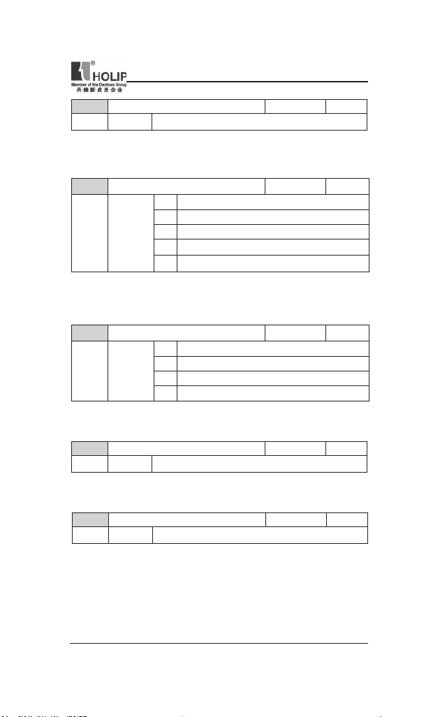
HLP-NV Series
C08.31 Addres s Default setting 1
Range [1 - 126]
● Funct ion: Select t he add ress for the bus.
FC -bus range is 1-126.
Modbus range is 1-247.
C08.32 FC Port Baud Rate Default se tti ng 2
Range [0] 240 0 Baud
[1] 4800 Baud
[2] 9600 Bau d
[3] 19200 Baud
[4] 38400 Bau d
● Funct ion: Select baud rate for FC Port.
● ATTEN TION! Changing baud rate will be ef fective after re sponding
to any ongoi ng bus-requests.
C08.33 FC Port Par ity Default setti ng 0
Range [0] Even Pa rity(1 stopbit)
[1] Odd par ity
[2]
[3] No Parit y (2 stopbit)
No Parit y (1 stopbit) Selec t this for Modbus RTU
● Funct ion: This pa rameter only affe cts Modbus a s FC bus always ha s
even par ity.
C08.35 Mini mum Response Delay Default set ting 0.010s
Range [0.001 -0. 500 s]
● Funct ion: Specif y m ini mum delay time between receivi ng a request
and transmitting a response.
C08.36 Max Resp onse Delay D efault setting 5.000s
Range [0.010 - 10.000 s]
● Fu nc tio n: Spe ci f y max imu m per mis si ble delay ti me bet we en
tra nsmitti ng a request and receiving a r esponse. Exceeding t his time
delay causes control word timeout.
HLP-NV Series
- 77 -
Page 83
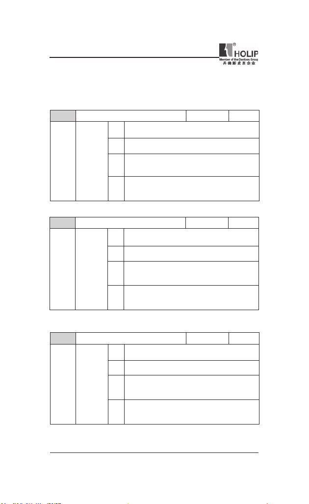
HLP-NV Series
8-5* Digital/Bus
Parameters for conguri ng control word Digit al/Bus merg ing.
ATTENTION! Parameters are only active when pa r. C08.01, C ontrol
SIte, is set to Digital and cont rol word [0].
C08.50 Coasting Select Default s etti ng 3
Range [0] Dig ital Input
Activation via a digita l input.
[1] Bus Ac tivation via ser ial
[2] LogicA nd Activation via ser ial
[3] LogicO r Activation via serial
● Funct ion:
C08.51 Quick Sto p Select Defa ult setting 3
Range [0] Dig ital Input
Activation via a digita l input.
[1] Bus Ac tivation via ser ial
[2] LogicA nd Activation via ser ial
[3] LogicO r Activat ion via se rial
● Funct ion:
Select control of coasting f unct ion via digital i nput and /or bus.
Select control of quick stop fu nction via digit al input and/or bu s.
commu nicat ion por t.
commu nicat ion por t and a digital
input.
commu nicat ion por t or a digit al
input.
commu nicat ion por t.
commu nicat ion por t and a digital
input.
commu nicat ion por t or a digit al
input.
C08.52 DC Brake Select Defa ult set ting 3
Range [0] Dig ital Input
Activation via a digita l input.
[1] Bus Act ivation v ia serial
[2] LogicA nd Activation via serial
[3] LogicO r Act ivation v ia ser ial
● Funct ion:
- 78 -
Select control of DC brake via digital i nput and /or bus.
HLP-NV Series
commu nicat ion por t.
commu nicat ion por t and a digital
input.
commu nicat ion por t or a digit al
input.
Page 84
HLP-NV Series
C08.53 Star t Select Default s etti ng 3
Range [0] Dig ital Input
Activation via a digita l input.
[1] Bus Act ivation v ia serial
[2] LogicA nd Activation via serial
[3] LogicO r Activation via serial
● Funct ion:
C08.54 Reversing Select Default set ting 3
Range [0] Dig ital Input
Activation via a digita l input.
[1] Bus Act ivation v ia serial
[2] LogicA nd Activation via serial
[3] LogicO r Activation via serial
● Funct ion:
C08.55 Set-up Select Default setti ng 3
Range [0] Dig ital Input
Activation via a digita l input.
[1] Bus Act ivation v ia serial
[2] LogicA nd Activation via serial
[3] LogicO r Activation via serial
● Funct ion:
Select control of sta rt function via digital input and/or bus.
Select control of rever sing function via digital input and/or bus.
Select control of set-up selection via digital input and/or bus.
commu nicat ion por t.
commu nicat ion por t and a digital
input.
commu nicat ion por t or a digit al
input.
commu nicat ion por t.
commu nicat ion por t and a digital
input.
commu nicat ion por t or a digit al
input.
commu nicat ion por t.
commu nicat ion por t and a digital
input.
commu nicat ion por t or a digit al
input.
HLP-NV Series
- 79 -
Page 85
HLP-NV Series
C08.56 Preset Reference Select Default setting 3
Range [0] Dig ital Input
Activation via a digita l input.
[1] Bus Act ivation v ia serial
[2] LogicA nd Activation via serial
[3] LogicO r Activation via serial
● Funct ion:
Select control of Preset Reference sele ction via digita l input and/
commu nicat ion por t.
commu nicat ion por t and a digital
input.
commu nicat ion por t or a digit al
input.
or bus.
8-9* Bus Feedback
Parameter for congu ring bus feedback.
C08.94 Bus feedb ack 1 Default setting 0
Range 0* [0x8000 - 0x7FFF]
Parameter group 14: Special Functions
Parameter group for con gur ing special f requency conver ter f unctions.
14-0* Inverter Switching
Parameters for conguri ng the inve rter switching.
C14.01 Switchi ng Frequency Default setting 1
Range [0] 2 K HZ
[1] 4KHZ
[2] 8KHZ
[4] 16KHZ
● Func tion: Select the switchi ng fr eque ncy in ord er to minimize e.g.
acoustic noise and power loss or maximizi ng efciency.
C14.03 Overmodulat ion Defau lt sett ing 1
Range [0] Of f Di s a b l e s th e ove r m od ul at io n
[1] On C on ne ct s th e ov e r mo d u l a t i on
- 80 -
HLP-NV Series
fu nct ion to avoid torque r ipple on
the motor shaft.
function to obtain a n output voltage
up to 15 % gr e a t e r t h a n m a i n s
voltage.
Page 86
HLP-NV Series
● Fu nction: Th is feat ur e allow s more accur at e spee d cont rol ne ar
and ove r nom in al sp e e d (50 /60 Hz) . Ano t h er ad v ant age wi t h
ove rm od ul at ion is th e abil it y of s tayi ng at a c on st an t spee d even
though mains is dropping.
14-1* Mains Monitoring
This parameter group supplies functions for handling imbalance on mains.
C14.12 Funct ion at mai ns imbalance Default setting 0
Range [0] Trip Frequency converter tr ips
[1] Warni ng Frequency conver ter issues a war ning.
[2] Disabled No action taken.
● Fu nc t io n: Ope ra t ion under se ve re mains imbalan ce condi ti on s
reduces drive l ift time.
Select function to take place when severe mains imbalance is detected.
14-2* Trip Reset
Parameters for con guring auto reset ha ndli ng, special t rip handl ing and
control card self test or in itialisation.
C14.20 Reset Mode Default sett ing 0
R ange [0] Manual Reset Perform reset via [reset]-but ton or dig ital
[1] AutoReset 1 P e r for ms on e au to m atic r es et af te r
[2] AutoReset 2 Per for ms t wo au tom at ic r e se ts a f te r
[3] AutoReset 3 Pe rfo rms thr ee aut om atic res et s af ter
[4] AutoReset 4 Per for ms fo u r au to mat ic re se ts af ter
[5] AutoReset 5 Per for ms fiv e au tom at ic res et s af ter
[6] AutoReset 6 P er fo rm s six au to m at ic re s et s af te r
[7] AutoReset 7 Pe rfor ms seve n a utom atic rese ts aft er
[8] AutoReset 8 Pe rfo r ms eig ht au tom at ic res et s a fte r
[9] AutoReset 9 Pe rfo rm s ni ne aut oma tic res ets afte r
[10] AutoRes et 10 P er fo rm s te n au to m at ic re se ts af ter
[11] AutoReset 15 Pe rf or ms fif teen aut om at ic rese ts after
[12] AutoRes et 20 Per for ms twe nty autom atic rese ts af ter
[13] Inf inite auto re set Pe rfo rms an inf in ite n umb er of
inputs.
trip ping.
trip ping.
trip ping.
trip ping.
trip ping.
trip ping.
trip ping.
trip ping.
trip ping.
trip ping.
trip ping.
trip ping.
automatic resets aft er tr ipping.
HLP-NV Series
- 81 -
Page 87

HLP-NV Series
● Funct ion: Select reset f unct ion afte r t ripping. Once reset, frequency
converter can be restarte d.
● warni ng: Motor may star t without warning.
C14.21 Automatic Resta rt Time D efault setting 10S
Range [0 - 60 0 s]
● Functi on: Ent er time inter val from trip to s tart of au tomatic reset
function.
Th is par am et er is a ct iv e when par. 14-20 , Reset Mo de , is set to
Automatic Reset [0] - [13].
C14.22 Opera tion Mode Defau lt sett ing 0
Range [0] Nor mal Op eration
Fre quenc y conver ter runs nor mal
[2] Initializ ation
Re set s all pa ram et ers to de faul t
Pa r. 14-22 also re ver ts to def au lt
operation.
sett ings , e xcept for C15.03, C15.04
and C15.0 5. Freq uency conve rt er
resets duri ng next powe r-up.
setting Nor mal Operatio n [0].
● Function: Use this para mete r for specify ing normal operation or t o
initialize all parameters, except par. C15.03, C15.04 and C15.05.
C14.26 Action At Inverte r Fault Default set ting 0
Range [0] Trip
[1] Warni ng
C14.41 AEO Mi nimu m Magne tisat ion Default setti ng 66%
Range [40 - 75%]
● Funct ion: Enter the mi ni mu m al lowable magne ti za tio n for AE O.
Select ing a low value red uces energy loss i n the motor, but m ay also
reduce resistance to sudden load changes.
- 82 -
HLP-NV Series
Page 88
HLP-NV Series
Parameter group 15: Drive Information
Parame ter group contai ni ng infor mat ion on operating da ta, hardwa re
cong urat ion, software version, etc.
15-0* Operating Data
Para mete r group conta ini ng ope rating data e.g. Op erat ing Hours, kWh
counters, Power Ups, etc.
C15.00 Opera ting Time Defau lt sett ing 0
Range [0 - 65535 days]
● Funct ion: View running hours of frequency converter.
The value is saved at power off and cannot be reset.
C15.01 Runn ing Hours Default s etti ng 0
Range [0 - 2147483647]
● Funct ion: View power consumpt ion in kW h as a mean value over one
hour.
Reset cou nter in par. C15.06, Reset kWh Counter.
C15.02 kWh Count er Defau lt sett ing 0
Range [0 - 65535]
● Funct ion: View power consumpt ion in kW h as a mean value over one
hour.
Reset cou nter in par. C15.06, Reset kWh Counter.
C15.03 Power Ups Defa ult setting 0
Range [0 - 2147483647]
● Fu nc ti on : Vi ew nu mb er of times frequency convert er has bee n
powered up.
Counter cannot be reset.
C15.04 Over Temps Defau lt sett ing 0
Range [0 - 65535]
● Funct ion: View number of times frequency conver ter has tr ipped due
to over temperat ure.
Counter cannot be reset.
HLP-NV Series
- 83 -
Page 89

HLP-NV Series
C15.05 Over Volts Defa ult setting 0
Range [0 - 65535]
● Funct ion: View number of times frequency converte r has tr ipped due
to over voltage.
Counter cannot be reset.
C15.06 Reset kWh Counter Defau lt sett ing 0
Range [0] Do Not Reset Cou nter is not reset.
[1] Reset Cou nter Counter is reset.
● Funct ion: This para meter cannot be selected via ser ial por t RS 485.
C15.07 Reset Running Hours Counter Default s etti ng 0
Range [0] Do Not Reset Cou nter is not reset.
[1] Reset Cou nter Counter is reset.
● Funct ion: This para meter cannot be selected via ser ial por t RS 485.
15-3* Fault Log
Thi s par ameter group contai ns a fault log showing reason s for the t en
latest t rips.
C15.30 Fault Log: Er ror Code Default setting 0
Range [0 - 255]
● Funct ion: View err or code an d look it up in VLT Mic ro De sig n
Guide.
C15.4* Drive Identication
Par ame ters containi ng read only infor mat ion abou t the hardwa re and
software con gur ation of the frequency converter.
C15.40 FC Type Default setting **
View FC typ e.
C15.41 Power Section Default setti ng **
View power section of frequency conver ter.
C15.42 Voltage Defa ult set ting **
View voltage of f requency conver ter.
- 84 -
HLP-NV Series
Page 90

HLP-NV Series
C15.43 Softwa re Version Default set ting **
View software ver sion of frequency convert er.
C15.46 Frequenc y Conver ter Order. No Default sett ing **
View order ing number for re -orde ring f reque ncy converter i n its
original con gur ation.
C15.48 LCP ID No Default setting **
View LCP ID nu mber.
C15.51 Frequenc y Conver ter Ser ial No Default setting **
View freq uency co nverter serial number.
Parameter group 16: Data Readouts
Par am et er grou p for data read -o ut s, e.g. actu al refere nc es, voltages ,
control, alar m, war ning and status words.
16-0* General Status
Parameters for reading t he general status , e.g. the calculated reference,
the act ive control word, status.
C16.00 Control Word Default set ting 0
Range [0 - 65535]
● Funct ion: View latest valid control word sent to frequency converter
via ser ial com munication port.
C16.01 Reference [Unit] Default set ting 0.000
Range [- 4999.000 - 4999.000]
● Funct ion: View total remote ref erenc e. Tota l referenc e is sum of
pulse, a nalog, preset, LCP potmeter, local bus and freeze reference.
C16.02 Reference % Default set ting 0.0
Range [-200.0 - 200.0%]
● Fun ction: View total remote reference in percent. Total r eferen ce
is su m of pulse, a nalog, preset , LCP p otmete r, loc al bus a nd freeze
reference.
HLP-NV Series
- 85 -
Page 91

HLP-NV Series
C16.03 Statu s Word Default setti ng 0
Range [0 - 65535]
● Functi on: View status word sent to fr equ ency convert er via ser ial
commu nication port.
C16.05 Main Act ual Value [%] Defau lt sett ing 0.00
Range [-100.00 - 100.00%]
● Function: View two -byt e word sent with stat us word to bus Master
repor ting main actual value.
16-1* Motor Status
C16.09 Custom Readout D efault setting 0.00
Range [0.00 – 9999.00%]
● Funct ion: Customized readout based on the setting of par.C0.32 and
par.C4.14.
C16.10 Power [kW] Defau lt sett ing 0k w
Range [0 - 99 kW]
● Funct ion: View out put power in kW.
C16.11 Power [hp] Default s etti ng 0 H p
Range [0 - 99 Hp ]
● Funct ion: View out put power inHp.
C16.12 Motor Voltage D efault se tting 0.0
Range [0.0 - 999.9 V]
● Funct ion: View motor phase voltage.
C16.13 Frequen cy D efault setting 0.0HZ
Range [0.0 - 40 0.0 Hz]
● Funct ion: View out put fre quency i n Hz.
C16.14 Motor Cu rrent Defau lt sett ing 0.00A
Range [0.00 - 1856.00 A]
● Funct ion: View motor phase cu rre nt.
C16.15 Frequen cy [%] Default setting 0.00
Range [-100.00 - 100.00%]
● Funct ion: View a two-byte word repor ting act ual motor frequency as
a percentage of par. X-XX
- 86 -
HLP-NV Series
Page 92

HLP-NV Series
C16.18 Motor Thermal Default se tti ng 0%
Range [0 - 100%]
● Fu nc tion: View ca lc ulate d the rmal moto r load as pe rcen tage of
estimated thermal motor loa d.
16-3* Drive Status
Parameters for repor ting t he stat us of the f reque ncy conver ter.
C16.30 DC Link Voltage D efault setting 0
Range [0 - 10000 V]
● Funct ion: View DC-link voltage.
C16.34 Heat sin k Temp. Defau lt sett ing 0
Range [0 -255
● Funct ion: View heat sink temperature of frequency converter.
C16.35 Inverter The rmal Default se tting 0%
Range [0 -100%]
● Function: View calcul ate d thermal load on f req uen cy conver ter in
relation t o estimated t herm al load on f reque ncy conver ter.
C16.36 Inv. Nom. Cur rent Default setti ng 0.00A
Range [0.01 - 10000.00 A]
● Funct ion: View cont inuous nominal inver ter cu rrent.
C16.37 Inv. Max. Current Default sett ing 0.00A
Range [0.1 - 10000.00 A]
● Funct ion: View int erm ittent maximum inverter current (150%).
]
℃
C16.5* Ref. & Feedb.
Parameters for repor ting t he reference and feedback input.
C16.50 Exter nal Refer ence Default setting 0.0%
Range [-200.0 - 200.0%]
● Funct ion: View sum of all exte rnal references in percent.
C16.51 Pulse Reference Defau lt sett ing 0.0%
Range [-200.0 - 200.0%]
● Funct ion: View actual pu lse input conver ted to a reference i n percent.
HLP-NV Series
- 87 -
Page 93

HLP-NV Series
C16.52 Feedback [ Unit] Default se tting 0.000
Range [- 4999.000 - 4999.000]
● Funct ion: View analog or pulse feedback in Hz.
16-6* Inputs and Outputs
Parameters for repor ting t he digit al and analog IO por ts.
C16.60 Digital Input RUN,F/R,RST,EMS Default set ting 0
Range [0 - 1111]
● Funct ion: View signal states from active digital i nputs.
C16.61 Digital Input JOG Defa ult setting 0
Range [0 - 1]
● Funct ion: View signal state on Digit al Input JOG.
C16.62 Analog I nput VI N (volt) Default setting 0.00
Range [0.00 - 10.00 V]
● Funct ion: View input voltage on analog input ter minal.
C16.63 Analog I nput VI N (current) Default se tti ng 0.00
Range [0.00 - 20.00 mA]
● Funct ion: View input cur rent on analog input terminal.
C16.64 Analog I nput AI N Defau lt sett ing 0.00
Range [0.00 - 20.00 mA]
● Fu ncti on: View act ual valu e at In pu t AIN eit her as reference or
protection value.
C16.65 Analog O utput AON [mA] Defau lt sett ing 0.00
Range [0.00 - 20.00 mA]
● Funct ion: View out put cur rent on a nalog Output AO.
C16.68 Pulse I nput D efault setting 0Hz
Range [20 - 5000 Hz]
● Funct ion: View input frequency on pulse input terminal.
C16.71 Relay Out put [bi n] Def ault set ting 0
Range [0 - 1]
● Funct ion: View relay setti ng.
- 88 -
HLP-NV Series
Page 94

HLP-NV Series
C16.72 Counte r A D efault setting 0
Range [-2147483648 -2147483647]
● Funct ion: View present value of Counter A.
C16.73 Counte r B Default setting 0
Range [-2147483648 -2147483647]
● Funct ion: View present value of Counter B.
16-8* FC Port
Parameter for viewing references from FC Por t.
C16.86 FC Port RE F 1 Def ault set ting 0
Range [-200 - 200]
● Funct ion: View currently received reference from FC Por t.
16-9* Diagnosis Read-Out
Parameters d isplayi ng alar m, warning and extended st atus words.
C16.90 Alar m Word Default setti ng 0
Range [0 - 0x FFFFFFFF]
● Funct ion: View alar m word sent via serial com munication port in hex
code.
C16.92 Warning Word Defau lt sett ing 0
Range [0 - 0x FFFFFFFF]
● Funct ion: View warning word s ent via serial communic ation port in
hex code.
C16.94 Ext. Stat us Word Defau lt sett ing 0
Range [0 - 0x FFFFFFFF]
● Funct ion: View extended warni ng word sent via serial communicat ion
port i n hex code.
HLP-NV Series
- 89 -
Page 95

HLP-NV Series
X . Ma i n t e n a n c e , Fa u l t In f o r m a t i o n a n d
Troubleshooting
Periodic al mainte nan ces and inspections will keep yo ur invert er in its
normal state for long time.
1. Precautions about Inspection and Maintenance
● Be sure to tu rn off t he power supply to the inver te r(R. S. T)fi rst
before the i nspection and maintenance.
● Aft er conr ming the main circuit power s upply h as been tu rne d off
and the disp lay has dis ap pe ar ed , wait until the int er nal indica to r
lamp for high voltage goes out before perform ing the i nspection and
maintenance.
● During the inspection, do not pull out or w rongly distribute the i nter nal
power supply, wires and cables. Other wise it will cause malf unction or
damage to the inverter.
● Do not l eave any screw or o the r pa rt inside the inverter dur in g the
installation, or it will result in the short circuit of circuit board.
● Keep the inverter cle an, free from dust, oil mist a nd moisture after the
installation.
2. Periodical Inspection and Maintenance items
● Check whether the power supply voltage confor ms to the rated voltage
of the inver ter.
(Pay special attention to that whether there is any d amage on the power
supply wi res and the motor.)
● Check whether the wiring ter minals and t he connectors are tight
(Check whether the power supply wires a nd termi nal connection w ires
have any broken strand).
● Ch eck whether there is dust , iron fi li ngs or cor rosive f lu id in th e
inverter.
● Measuring t he insulation i mpedance of the inverter is forbidden.
● Examine the output voltage, out put cu rrent and out put frequency of the
inverter.
(The measur ing results should not have too big diffe rence.)
● Che ck wheth er the ambient tempe ra tu re of th e in ver ter is betw een
-5℃ and 40℃ and wh et her the installation env iron ment has good
ventilation.
● Che ck whethe r the humid ity is kept between 5% and 90% (wit hout
condensation).
- 90 -
HLP-NV Series
Page 96

HLP-NV Series
● Check whether t he motor makes unusual noises or abnor mal vibration
in ru nni ng.
(The inverte r should not b e inst alled in a place wit h high vibration.)
● Please ma ke periodical cleaning of vent holes.
3. Fault Indication and Troubleshooting
The inverter of HLP-NV se ries is relatively perfect ive with t he protection
functions of overload, i nter-pha se shor t circuit, ea rth short ci rcuit, undervoltage, overheati ng and over-cu rrent, etc. When a p rote ction function
happens with the inverter please check the reason s of faults accord ing to
the information liste d in the t able below. The i nver ter can b e rest ar ted
after the disposal. If the fault cannot be disposed please cont act t he local
distributor.
Fault Proce ss metho d
1. Motor ru ns
unsteadily
2. Motor ca nnot rotate
3. Br a ki ng fu nct ion
cannot take ef fect
4. No fau lt message or
displyed
5. Motor cannot rotate
and no fault message
displyed
Motor runs un stead ily but not wa rni ngs issued, please
check the seeti ngs of mot or parameter, i f no effect,
please co ntact holip.
Make su re no war ning o r alar m occured.
If any war ni ng or ala rm occu rre d, pl ea se refer to
correspond ing tr oublesho oting section .
If no warning or ala rm occurre d,please refer to item 5.
Please make sur e if in put voltage is correct and refer
to item 4 if it is corr ect.
Please refe r to bra king f unct ion sect ion
Make su re the f use is not broken
Make sure the control card is not overloaded , and it
is overlo ad ed or 24V is sho rt ed ,pl ease remove the
conne ction of control term inal. Make su re if a ny fault
message is displayed,and if no, please conta ct Holip
Press [ENT ER] key on LCP and m ake su re the s creen
is active, i.e. the d isplay ca n be switched or p arameter
can be ed ited.
Ple ase make sure if the sc reene d cabl e use d a nd
conne cted correc tly.
If d ispl ay is no pr obl em, ple as e ma ke su re th e
con necti on betwe en motor a nd the drive i s correct
an d the n ope ra te th e d rive in hand mode . Plea se
contact Holip if motor can not rota te.
HLP-NV Series
- 91 -
Page 97
HLP-NV Series
4. Fault code description and Analysis
Fault Display
Fault Content s
& Descr iption
Disposal methods
Live zero
error
Mains phase
loss
DC over
voltage
DC unde r
voltage
Inver ter
overloaded
Motor
ETR over
tempe ratu re
Signal on term inal VIN or AIN is less
th an 50% of val ue set in par. C6.10,
C6.12 and C6.22
Mis sin g phase on sup ply side, or t oo
high voltage imbalance. C heck supply
voltage.
Int erme di ate ci rcu it vo ltage exce eds
limit .
In ter med iat e ci rcu it volta ge drop s
below “voltage war ning low” limit .
More tha n 100% overloa d for too long.
Mo tor is too hot due to mor e th an
100% overload for too long.
Torque lim it
- 92 -
HLP-NV Series
Torque exc eeds value set in either p ar.
C4.16 or C4.17.
Page 98
HLP-NV Series
Fault Display
Over Current Invert er peak curr ent lim it is exceede d.
Ear th fault
Short Circuit
Fault Content s
& Descr iption
Control word
timeout
Brake re sistor
shortcircu ited
Disposal methods
Dis ch a r ge fro m ou t put p ha ses to
ground.
Sh or t-c irc uit in mo tor or on motor
terminals.
No com mu n i c at ion t o f re q u e n cy
conver ter
Brake t ransistor is short-circu ited, t hus
brake f unct ion is dis conne cted.
Brake chopper
shortcircu ited
Brake t ransistor is short-circu ited, t hus
brake f unct ion is dis conne cted.
HLP-NV Series
- 93 -
Page 99
HLP-NV Series
Fault Display
Brake check
Fault Content s
& Descr iption
Power board
over temp
Motor pha se
U missi ng
Motor pha se
V missi ng
Motor pha se
W missi ng
Disposal methods
Br ak e re si st o r i s no t c o n ne c t e d /
working
He at -si nk cut- out te mpe rat ure h as
been re ached.
Moto r pha se U is missi ng. Check the
phase.
Moto r pha se V is missi ng. Check the
phase.
Motor phaseW is m issing. Check the
phase.
Inte rnal fault Contac t local HOLI P supplier.
- 94 -
24 V supply
low
Ex te r nal 2 4 V DC b ack -u p pow er
supply may b e overloaded.
HLP-NV Series
Page 100

HLP-NV Series
Fault Display
Fault Content s
& Descr iption
AMT che ck
Unom and
Inom
AMT low
Inom
Motor
ther mistor
over
tempe ratu re
Mechan ical
Brake Low
Drive
Initialise d to
Default Value
Disposal methods
Wrong set ting for motor voltage a nd/or
motor cu rrent.
Mo to r cu rr en t is to o low. Ch ec k
settings.
Ther mistor or t herm istor connection is
disconnete d
Actua l motor cu rrent has not exceeded
“re lea se brake” curr ent wit hi n “star t
delay” time window
All p arame ter s ettin gs are initia li zed
to default settings.
Note: A=Alarm E=Warning
HLP-NV Series
- 95 -
 Loading...