


HLP-C100 Series Operating
Manual
Introduction
Thank you for purchasing and using the minidrive of HLP-C100 series. Please read caref ully the operation manual before putting the drive to use so as to correctly install and operate the drive, give f ull play to its
f unctions and ensure the safety. Please keep the operation manual handy for f uture reference, maintenance, inspection and repair.
Due to the driveof a kind of powerelectronics product it must be installed, tested and adjusted with specialized electrical engineering workers.
The marks of  (Danger),
 (Caution)and other symbols in the manual remind you of the safety and prevention cautions during the handling, installation, running and inspection. Please follow these instructions to make sure the safe use of the drive. In case of any doubt please contact our local agent for consultation. Our professional persons are willing and ready to serve you.
The manual is subject to change without notice.

|
|
|
|
|
|
HLP-C100 Series |
||
|
|
|
|
|
|
|||
|
|
|
|
|
|
Index |
|
|
Introduction |
|
|
|
I |
||||
Chapter 1 Safety Precautions |
- 1 - |
|
||||||
|
1.1 Before Power-up |
-1 - |
|
|||||
|
|
|
|
|||||
|
1.2 During the Power-up |
- 2 - |
|
|||||
|
|
|
|
|||||
|
1.3 During the Operation |
- 3 - |
|
|||||
|
|
|
|
|
||||
1.4 |
After the Power-off |
- 3 - |
|
|||||
Chapter 2 Standards and Specifications |
- 4 - |
|
||||||
|
|
|
|
|||||
|
2.1 Label Description |
- 4 - |
|
|||||
|
|
|
|
|
||||
2.2 |
Particular Specifications |
- 5 - |
|
|||||
|
|
|
|
|
||||
2.3 |
Technical Specifications |
- 5 - |
|
|||||
|
|
|
|
|
|
|
|
|
2.4 |
Derating Specifications |
- 7 - |
|
|||||
|
|
|
|
|
|
|
|
|
2.5 |
Accessories |
- 7 - |
|
|||||
Chapter 3 Mechanical and Electrical Installation |
- 8 - |
|
||||||
|
3.1 |
Mechanical Installation |
- 8 - |
|
||||
|
|
|
|
|
||||
|
|
3.1.1 Installation Environment Requirements |
- 8 - |
|
||||
|
|
|
|
|
||||
|
|
3.1.2 External and Installation Dimensions |
- 8 - |
|
||||
|
|
|
|
|
||||
|
|
3.1.3 Installation and Direction |
- 9 - |
|
||||
|
|
|
|
|
||||
|
|
3.1.4 Accessories Installation |
- 11 - |
|
||||
|
|
|
|
|
||||
3.2 |
Peripheral Electrical Devices |
- 14 - |
|
|||||
|
|
|
|
|
||||
|
|
3.2.1 Selection of MCCB/Fuse/Contactor |
- 15 - |
|
||||
|
|
|
|
|
||||
|
|
3.2.2 Selection of Braking Unit and Braking Resistor |
- 16 - |
|
||||
|
|
|
|
|
|
|
||
|
|
3.2.3 |
|
Selection of AC Input and Output Reactor |
- 17 - |
|
||
|
|
|
|
|
||||
|
|
3.2.4 Selection of EMC Filter |
- 18 - |
|
||||
|
|
|
|
|||||
|
3.3 Description of Main Circuit |
- 18 - |
|
|||||
|
|
|
|
|
||||
|
|
3.3.1 Schematic of Main Circuit Terminals |
- 18 - |
|
||||
|
|
|
|
|||||
|
|
3.3.2 Main Circuit Terminal Screws and Wiring Recommended |
||||||
|
|
|
|
|
|
|
||
|
|
|
|
Specifications |
- 19 - |
|
||
|
|
|
|
|
||||
3.4 |
Description of Control Circuit |
- 19 - |
|
|||||
|
|
|
|
|
||||
|
|
3.4.1 Schematic of Control Circuit Terminals |
- 19 - |
|
||||
|
|
|
|
|||||
|
|
3.4.2 Control Terminals’ Screws and Wiring Recommended |
|
|||||
|
|
|
|
|
|
|
||
|
|
|
|
Specifications |
- 20 - |
|
||
|
|
|
|
|
|
|
|
|
|
|
3.4.3 Control Curcuit Wiring |
- 21 - |
|
||||
|
|
|
|
|
|
|
||
|
|
3.4.4 |
|
Digital Input Terminals Usage Specification |
- 21 - |
|
||
|
|
|
|
|||||
|
3.5 EMC instructions |
- 22 - |
|
|||||
|
|
|
|
|
||||
|
|
3.5.1 Introduction to EMC Standard |
- 22 - |
|
||||
|
|
|
|
|
||||
|
|
3.5.2 Noise Abatement |
- 23 - |
|
||||
|
|
|
|
|
||||
|
|
3.5.3 Grounding |
- 23 - |
|
||||
HLP-C100 Series Operating Manual

HLP-C100 Series |
|
|
|
||
|
|
||||
|
|
|
|
||
|
|
3.5.4 Leakage Current Suppression |
- 23 - |
||
|
|
|
|
|
|
|
|
3.5.5 Induction Voltage Suppression |
- 24 - |
||
Chapter 4 Operation and Display Interface |
- 25 - |
||||
|
4.1 |
Local Control Panel |
- 25 - |
||
|
|
|
|
||
4.2 |
Parameter Setting |
- 26 - |
|||
|
|
|
|
||
4.3 |
FWD/REV Status |
- 28 - |
|||
|
|
|
|
||
4.4 |
Data Read-outs |
- 29 - |
|||
|
|
|
|
||
4.5 |
View Alarm Record |
- 30 - |
|||
|
|
|
|
||
4.6 |
View State Parameter |
- 31 - |
|||
|
|
|
|
||
4.7 |
LED Display |
- 32 - |
|||
Chapter 5 Parameter Overview |
- 33 - |
||||
Chapter 6 Parameter Description |
- 43 - |
||||
|
|
|
|
||
6.1 |
Group 00: Operation/Display |
- 43 - |
|||
|
|
|
|
||
6.2 |
Group 01: Load and Motor |
- 45 - |
|||
|
|
|
|
|
|
6.3 |
Group 02: Brakes |
- 51 - |
|||
|
|
|
|
||
6.4 |
Group 03: Reference/Ramps |
- 53 - |
|||
|
|
|
|
||
6.5 |
Group 04: Limits/Warnings |
- 58 - |
|||
|
|
|
|
||
6.6 |
Group 05: Digital In/Out |
- 61 - |
|||
|
|
|
|
||
6.7 |
Group 06: Analog In/Out |
- 64 - |
|||
|
|
|
|
||
6.8 |
Group 07: Controllers |
- 67 - |
|||
|
|
|
|
||
6.9 |
Group 08: Communication |
- 69 - |
|||
|
|
|
|
||
6.10 |
Group 14: Special Functions |
- 72 - |
|||
|
|
|
|
||
6.11 |
Group 15: Drive Information |
- 76 - |
|||
|
|
|
|||
|
6.12 Group 16: Data Readouts |
- 78 - |
|||
Chapter 7 Quick Application Guide |
- 81 - |
||||
|
|
|
|
||
7.1 |
Using LCP to Start/Stop the Drive |
- 81 - |
|||
|
|
|
|
||
7.2 |
Using Digital Input Terminals to Start/Stop the Drive |
- 81 - |
|||
|
|
|
|
|
|
|
|
7.2.1 Two-line Mode 1 |
- 81 - |
||
|
|
|
|
|
|
|
|
7.2.2 Two-line Mode 2 |
- 81 - |
||
|
|
|
|
||
|
|
7.2.3 Three-line Mode 1 |
- 82 - |
||
|
|
|
|
||
|
|
7.2.4 Three-line Mode 2 |
- 82 - |
||
|
|
|
|
||
7.3 |
Multi-speed |
- 83 - |
|||
|
|
|
|
||
7.4 |
Analog Input as the Frequency Source |
- 83 - |
|||
|
|
|
|
||
7.5 |
Speed up/down |
- 84 - |
|||
|
|
|
|
||
7.6 |
Parameter Initialization |
- 84 - |
|||
Chapter 8 Faults and Solutions |
- 85 - |
||||
|
8.1 |
Fault List |
- 85 - |
||
Chapter 9 Maintenance |
- 88 - |
||||
|
|
|
|
||
9.1 |
Note |
- 88 - |
|||
|
|
|
|
||
9.2 |
Storage and Transport |
- 88 - |
|||
Appendix A Modbus Communication Specification |
- 89 - |
||||
Appendix B Copy Card Specification |
- 101 - |
||||
HLP-C100 Series Operating Manual

HLP-C100 Series
Chapter 1 Safety Precautions
Caution Indicates misuse may damage the inverter or mechanical system .
Danger Indicates misuse may result in casualty.
1.1 Before Power-up
 Caution
●Check to be sure that the voltage of the main circuit AC power supply matches the input voltage of the drive.
●Install the drive in a safe location, avoiding high temperature, direct sunlight, humid air or water.
●The drive can only be used at the places accredited by our company. Any unauthorized working environment may have the risks of fire, gas explosion, electric shock and other incidents.
●If more than one drive installed on the same control cabinet, make additional cooling fan, so that the inside temperature is lower than 40, in order to prevent overheating or fire occurs.
●It will affect the service life of the drive if a contactor is installed on the input side to control the start and stop. Generally it is required to control it through terminal commands. Special attention should be paid to its use in the case of the start and stop more frequently places.
●Do not install any switch component like circuit breaker or contactor at the output of the drive. If any of such components must be installed due process and other needs, it must be ensured that the drive has no output when the switch acts. In addition, it is forbidden to install any capacitor for improvement of power factor or any varistor against thunder at the output. Otherwise it will cause malfunctions, tripping protection and damages of components of the drive.
●Please use an independent power supply for the drive. Do avoid using the common power supply with an electrical welder and other equipment with strong disturbance. Otherwise it will cause the drive to protect or even damage the drive.
●Do not make any high voltage test with any component inside the drive. These semi-conductor parts are subject to the damage of
HLP-C100 Series Operating Manual |
- 1 - |
HLP-C100 Series
high voltage.
●The IC board of the drive are susceptible to the effect and damage of static electricity. Don’t touch the main circuit board.
●Installation, commissioning and maintenance must be performed by qualified professional personnel.
●Don’t carry the front cover of the drive directly when handling.
It should be handled with the base to prevent the front cover off and avoid the dropping of the drive, which may possibly cause the injuries to people and the damages to the drive.
 Danger
●Be sure to turn off the power supply before wiring.
●Mount the drive in the metal and other non-combustible materials to avoid the risk of fire.
●Don’t install the drive in a space with explosive gas, otherwise, they lead to explosion.
●R, S, T terminals are power input terminals, never mixed with U.V.W terminals. Be sure that the wiring of the main circuit is correct. Otherwise it will cause damages of the drive when the power is applied to it.
●The terminal of must be grounded separately and never connected toN-line. Otherwise it will easily cause the protection or errors of thedrive.
●Do not dissemble or modify any internal connecting cord, wiring or component of the drive by yourself.
●Never remodel it or exchange control boards and components by yourself. It may expose you to an electrical shock or explosion, etc.
●Keep the drivefrom the reach of children or persons not concerned.
1.2 During the Power-up
 Danger
● Do not plug the connectors of the drive duringthe power upto avoid any surge into the main control board due to plugging, which might cause the damage of thedrive.
- 2 - |
HLP-C100 Series Operating Manual |

HLP-C100 Series
1.3 During the Operation
 Caution
●Do not measure the signals on circuit boards while the drive is running to avoid danger.
●The drive has been optimized before sold. Please make proper adjustments according to the desired functions.
●Do consider the vibration, noise and the speed limit of the motor bearings and the mechanical devices.
 Danger
●Never connect or disconnect the motor set while thedrive is in running. Otherwise it will cause over-current trip and even burn up the main circuit of the drive.
●Do not come close to the machine when the ResetFunction is used to avoid anything unexpected. The motor may automatically recover from fault.
1.4 After the Power-off
 Caution
●Even in the case of the main power, the other voltage inputs and the share load (linkage of DC intermediate circuit) all have been disconnected from the mains; the internal of the drive may still have residual energy. Before touching any potentially live parts of the drive, please wait at least 4 minutes. Otherwise, it may expose you to a risk of electrical shock.
HLP-C100 Series Operating Manual |
- 3 - |
HLP-C100 Series
Chapter 2 Standards and Specifications
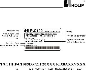
2.1 Label Description
Significance of the product type code:
1-8 |
HLP-C100 |
Indicate Product Series |
|
9-12 |
0D37 |
Indicate0.37KW |
|
13-14 |
21 |
Indicate1-Phase |
AC 220V |
|
23 |
Indicate 3-Phase |
AC 220V |
|
43 |
Indicate 3-Phase |
AC 380V |
15-17 |
P20 |
IP rating is 20 |
|
18 |
X |
Without AC choke |
|
|
A |
With AC choke |
|
19 |
X |
Without Brake unit |
|
|
B |
With Brake unit |
|
20 |
X |
Without DC choke |
|
|
B |
With DC choke |
|
21 |
1 |
Control panel with LED display and potentiometer |
|
22 |
C |
With coating on PCB |
|
23 |
X |
Reserved |
|
24 |
0 |
Domestic sale |
|
|
1 |
Overseas sale |
|
25 |
A |
Without RS485 |
|
|
B |
With RS485 |
|
26-27 |
XX |
Reserved |
|
28-31 |
VXXX |
Indicate software version number, such as |
|
|
|
V235means the version number is 2.35. |
|
Note: Without RS485 is standard configuration, With RS485 is optional, please specif y when ordering.
- 4 - |
HLP-C100 Series Operating Manual |
HLP-C100 Series
2.2 Particular Specifications
Model |
|
Input voltage |
|
Input |
Output |
Rated |
Suitable |
Net |
|
|
current/ |
current/ |
power/ |
motor/ |
weight/ |
||
|
|
|
|
A |
A |
KW |
KW |
KG |
HLP-C1000D3721 |
1×200-240V50/60Hz |
6.1 |
2.2 |
0.37 |
0.37 |
0.84 |
||
HLP-C1000D7521 |
1×200-240V50/60Hz |
11.6 |
4.2 |
0.75 |
0.75 |
0.84 |
||
HLP-C10001D521 |
1×200-240V50/60Hz |
18.7 |
6.8 |
1.5 |
1.5 |
0.84 |
||
HLP-C1000D3723 |
3×200-240V50/60Hz |
3.5 |
2.2 |
0.37 |
0.37 |
0.84 |
||
HLP-C1000D7523 |
3×200-240V50/60Hz |
6.7 |
4.2 |
0.75 |
0.75 |
0.84 |
||
HLP-C10001D523 |
3×200-240V50/60Hz |
10.9 |
6.8 |
1.5 |
1.5 |
0.84 |
||
HLP-C1000D7543 |
3×380-440V50/60Hz |
3.5 |
2.2 |
0.75 |
0.75 |
0.84 |
||
|
|
3×440-480V50/60Hz |
3.0 |
2.1 |
|
|
|
|
HLP-C10001D543 |
3×380-440V50/60Hz |
5.9 |
3.7 |
1.5 |
1.5 |
0.84 |
||
3×440-480V50/60Hz |
5.1 |
3.4 |
||||||
HLP-C10002D243 |
3×380-440V50/60Hz |
8.5 |
5.3 |
2.2 |
2.2 |
0.84 |
||
|
|
3×440-480V50/60Hz |
7.3 |
4.8 |
|
|
|
|
2.3 Technical Specifications |
|
|
|
|
|
|
||
|
|
|
|
|
|
|||
|
Item |
|
|
Specification |
|
|||
|
Supply voltage |
|
Single/Three phase200~240V-20%~+10%; |
|||||
|
|
Three phase 380~480V -20%~+10%; |
||||||
Power supply |
|
|
|
|||||
Frequency |
|
48~62Hz; |
|
|
|
|||
|
Max. imbalance |
|
3%; |
|
|
|
|
|
Motor output |
Output voltage |
|
Three phase 0-100%of supply voltage; |
|||||
Output frequency |
|
0-400Hz; |
|
|
|
|||
|
|
|
|
|
||||
|
Control mode |
|
V/F, VVC+; |
|
|
|
||
|
Start torque |
|
0.5Hz |
150%; |
|
|
|
|
|
Overload capacity |
|
150% 60s; |
|
|
|
||
|
PWM switch frequency |
2~16kHz; |
|
|
|
|||
|
Speed setting resolution |
|
Digital: 0.001Hz; Analogy: 0.5‰ of the |
|||||
Main control |
|
max. operating frequency ; |
|
|||||
Speedopen-loop control |
|
30~4000 rpm:tolerance±8 rpm; |
|
|||||
functions |
accuracy |
|
|
|
|
|
|
|
|
Cont rol com ma nd |
|
LCP, digital terminal, local bus; |
|
||||
|
source |
|
|
|
|
|
|
|
|
Freq uency set t i ng |
|
LCP, analog, pulse, local bus; |
|
||||
|
source |
|
|
|
|
|
|
|
|
Ramp control |
|
Selectable 8-speed steps ramp up and |
|||||
|
|
down times0.05-300.00s; |
|
|
||||
|
|
|
|
|
|
|||
|
|
|
|
|
|
|
|
|
|
|
HLP-C100 Series Operating Manual |
|
- 5 - |
||||

HLP-C100 Series
|
Item |
Specification |
|
Basic |
Speed Open-loop Control; Process Closed-loop Control; Slip |
|
|
Compensation;Torquecompensation;Automatic Voltage Regulation; |
|
||
Functions |
V/F Control, DC Brake; Speed Limit; Current Limit; FlyingStart; |
|
|
|
Reset Function; |
|
|
Application |
Jogging; Multi-speed |
Control via Digital input; Mechanical |
|
Functions |
Braking; UP/DOWN; Catch up/Slow down; Counter. |
|
|
|
Missing Motor Phase Protection; Low-voltage Protection; Over- |
|
|
Protection |
voltage Protection; Over-current Protection; Output Phase Loss |
|
|
Protection; Output Short Circuit Protection; Output Grounding |
|
||
Functions |
Fault Protection;Live Zero Timeout Function;ButtonFreeze; |
|
|
|
Duplicate Fails; LCP Invalid; LCP Incompatible; Parameter Read- |
|
|
|
only; Reference Out of Range; Invalid While Running etc. |
|
|
|
|
5 digital inputs; |
|
|
Input |
1analog input, both can receive voltage |
|
Control |
|
or current signals. |
|
terminals |
Output |
1 relay output; |
|
|
Power supply |
1+10V,max current output10mA; |
|
|
Communication* |
RS+, RS-, max baud rate 38400bit/s; |
|
|
8 segments, 5 numeric |
Display f requency, warnings, status |
|
|
displays |
and so on; |
|
|
Indicator |
Light FWD, REV, HZ, A, RPM display |
|
|
various status of the drive; |
|
|
|
|
|
|
Display |
|
Frequency setting, output f requency, |
|
|
feedback value, output current, DC |
|
|
|
Data read-outs |
link voltage, output voltage, output |
|
|
power, input terminals state, output |
|
|
|
|
terminals state, analogue input , |
|
|
|
analogue output, 1-10 fault records and |
|
|
|
accumulated working time etc.; |
|
|
Enclosure |
IP20; |
|
|
Ambient temperature |
-10 ~50 , derating use when over 40 ; |
|
|
Humidity |
5%-85% (95% without condensation); |
|
Environment |
Vibration test |
1.14g; |
|
Max. altitude above sea |
1000m, derating use when more than |
|
|
|
|
||
|
level |
1000 meters; |
|
|
Motor cable length |
Shield cable: 5 meters, unshield cable: 50 |
|
|
meters; |
|
|
|
|
|
|
others |
DC choke |
None; |
|
Braking unit |
≥220/380V1.5kWBuilt-in |
|
|
|
|
||
|
|
|
|
- 6 - |
HLP-C100 Series Operating Manual |
||
HLP-C100 Series
2.4 Derating Specifications
Derating for ambient temperature: If the drive is operated over 40 ambient temperature, the continuous output current should be decreased.The drive has been designed for operation at max 50 ambient temperationwith one motor size smaller than normal.Continuous operation at full load at 50 ambient temperation will reduce the lifetime of the drive.
Derating for low air pressure: The cooling capability of air is decreased at low air pressure. Below 1000m altitude no de-rating is necessary but above 1000m the ambient temperature or the maximum output current should be decreased. Dcrease the output by 1% per 100m altitude above 1000m or reduce the max. ambient temperature by 1degree per 200m.
2.5 Accessories
Cradle-01 LCP-02 
Network Cable
CopyCard-01 LCP-03 
Model |
Specification |
Remark |
|
|
T h e s t a n d a r d le n g t h of |
|
|
LCP-02 |
extension cable is 15 meters |
Optional, please specif y |
|
|
when mounting LCP on control |
when ordering |
|
|
cabinet. |
|
|
|
LCP-03 has the same installation |
Optional, please specif y |
|
LCP-03 |
dimensions with HLP-A control |
||
|
panel (OP-AB01). |
when ordering |
|
|
|
|
|
Cradle-01 |
For LCP-02 installation. |
Optional, please specif y |
|
when ordering |
|
||
|
|
|
|
CopyCard-01 |
Copy Card can copy parameters |
Optional, please specif y |
|
f rom one drive to another. |
when ordering |
|
|
Network |
Connect LCP to the drive when |
Do not offer, self |
|
mou nting LCP on cont rol |
|
||
Cable |
cabinet. |
procurement |
|
|
|
|
|
|
|
|
|
|
HLP-C100 Series Operating Manual |
- 7 - |
|
HLP-C100 Series
Chapter 3 Mechanical and Electrical Installation
3.1Mechanical Installation
3.1.1Installation Environment Requirements
1 Ambient temperature in the range of -10 ~ 50 ;
2 Drive should be installed on surface of flame retardant object, with adequate surroundingspace for heat dissipation;
3 Installation should be performed where vibration is less than 1.14g; 4 Avoid from moisture and direct sunlight;
5 Do not expose to an atmosphere with flammable gases, corrosive gases, explosive gasesor other harmful gases;
6 Protect the cooling fan by avoiding oil, dust and metal particles;
7 Prevent drilling residues, wire ends and screws falling into drive;
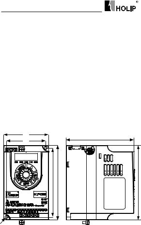
3.1.2 External and Installation Dimensions
B |
A |
C D |
F
E |
D |
Single/three phase 220V 0.37~1.5kW and three phase 380V 0.75~2.2kW
- 8 - |
HLP-C100 Series Operating Manual |
HLP-C100 Series
External and installation dimensions(unit:mm)
Model |
A |
B |
C |
D |
E |
F |
HLP-C1000D3721 |
|
|
|
|
|
|
HLP-C1000D7521 |
|
|
|
|
|
|
HLP-C10001D521 |
|
|
|
|
|
|
HLP-C1000D3723 |
|
|
|
|
|
|
HLP-C1000D7523 |
74 |
85 |
130 |
140 |
127 |
5 |
|
|
|
|
|
|
|
HLP-C10001D523 |
|
|
|
|
|
|
|
|
|
|
|
|
|
HLP-C1000D7543 |
|
|
|
|
|
|
|
|
|
|
|
|
|
HLP-C10001D543 |
|
|
|
|
|
|
HLP-C10002D243 |
|
|
|
|
|
|
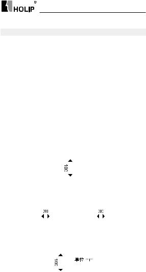
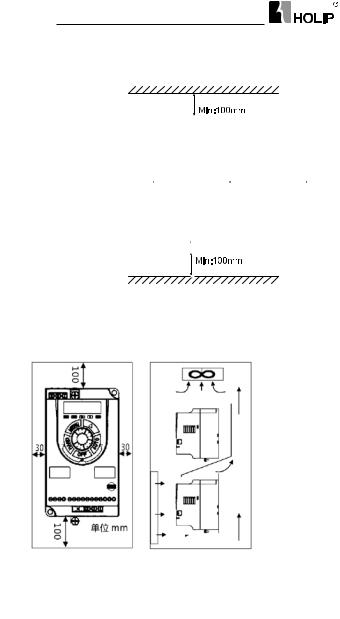
3.1.3 Installation and Direction
1. Single Installation
The drive must be installed vertically with smooth ventilation. Enough space must be left around the drive to ensure good cooling, as shown below (unit: mm):
|
|
|
|
|
|
|
|
|
|
|
|
|
|
|
|
|
|
|
|
|
|
|
|
|
|
|
|
|
|
|
|
|
|
|
|
|
|
|
|
|
|
|
|
|
|
|
|
|
|
|
|
|
|
|
|
|
|
|
|
|
|
|
|
|
|
|
|
|
|
|
|
|
|
|
|
|
|
|
|
|
|
|
|
|
|
|
|
|
|
|
|
|
|
|
|
HLP-C100 Series Operating Manual |
- 9 - |
||||||||||
HLP-C100 Series
2. Side by Side Installation
The drive can be mounted side by side, a minimum space must be reserved above and below the enclosure, as shown below:
3.Upper and Lower Installation
If several drives need to be installed together in one cabinet, upper and lower installation can be adopted. Enough space must be reserved to ensure effective cooling, as shown below:
- 10 - |
HLP-C100 Series Operating Manual |
HLP-C100 Series
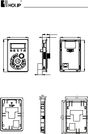
3.1.4 Accessories Installation
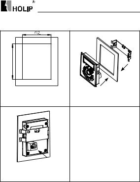
1. LCP-02 Installation
The external dimensions of LCP-02 are shown below (unit: mm):
|
21.7 |
57.1 |
59.5 |
12.8 |
|
| <![if ! IE]> <![endif]>92.6 |
|
<![if ! IE]> <![endif]>89.2 |
|
13.3 |
|
When installing LCP-02 outside, a cradle is needed. The external dimensions of the cradle are shown below (unit: mm):
HLP-C100 Series Operating Manual |
- 11 - |
HLP-C100 Series
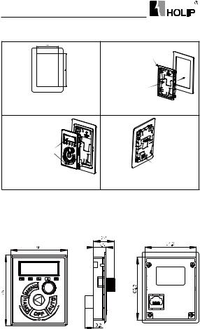
The installation steps of LCP-02 are shown below:
|
This cradle is suitable for 1.0-2.0mm |
|
t hick ness sheet |
|
metal parts |
|
Press and hold |
|
the snap roots when |
|
installation, using |
|
buckle deformation |
Step1: Open a hole in line with the size of |
install sheet metal. |
the control panel in the position need to |
Step2:Install the LCP according to |
install the LCP, holesize,asshown: |
the direction of the arrow. |
Recommended |
|
to install vertical |
|
mounting position |
|
arrow, press with |
|
uniform force. |
|
Step 3:The LCP is installed in the cradle, |
Step4:Install theexternal LCPcommunication |
cable,insertintoRJ45terminalfrom thebottom |
|
according to the direction of the arrow. |
of hole. |
2. LCP-03 Installation
The external dimensions of LCP-03 are shown below (unit: mm):
- 12 - |
HLP-C100 Series Operating Manual |
HLP-C100 Series
The installation steps of LCP-03 are shown below:
Step 1: Open a hole in the control panel where it is needed to install LCP-01 or LCP-02, the hole size is as shown.
Step 3: Install the LCP commun-ication cable, insert into RJ45 terminal from the bottom hole.
HLP-C100 Series Operating Manual |
- 13 - |
HLP-C100 Series
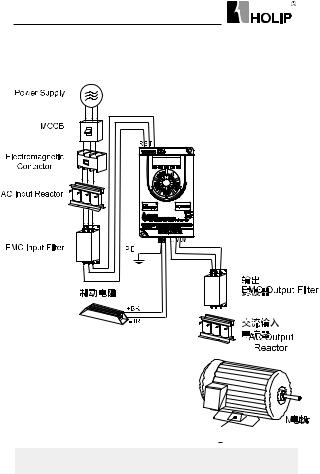
3.2 Peripheral Electrical Devices
The peripheral electrical devices of the drive are shown below:
|
|
|
|
|
|
|
|
|
|
|
|
|
|
|
|
|
|
|
|
|
|
|
|
|
|
|
|
|
|
|
|
|
|
|
|
|
|
|
|
|
|
|
|
|
|
|
|
|
|
|
|
|
|
|
|
|
|
|
|
|
|
|
|
|
|
|
|
|
|
|
|
|
|
|
|
|
|
|
|
|
|
|
|
|
|
|
|
|
|
|
|
|
|
|
|
|
|
|
|
|
|
|
|
|
|
|
|
|
|
|
|
|
|
|
|
|
|
|
|
|
|
|
|
|
|
|
|
|
|
|
|
|
|
|
|
|
|
|
|
|
|
|
|
|
|
|
|
|
|
|
|
|
|
|
|
|
|
|
|
|
|
|
|
|
|
|
|
|
|
|
|
|
|
|
|
|
|
|
|
|
|
|
|
|
|
|
|
|
|
|
|
|
|
|
|
Part |
|
Mounting |
|
Function Description |
|
|
|||||||
|
Location |
|
|
|
|||||||||
|
|
|
|
|
|
|
|
|
|
|
|
|
|
MCCB |
Power |
Interrupt the power supply when |
|
|
|||||||||
receiving side |
overcurrent occurs ondownstream devices. |
|
|
||||||||||
|
|
|
|||||||||||
|
Between |
Do not start and stop the drive frequently |
|
|
|||||||||
Contactor |
MCCB and |
by switchingthe contactor on and off (less |
|
|
|||||||||
|
drive input |
than twice per minute) noruse it to directly |
|
|
|||||||||
|
side |
start the drive. |
|
|
|||||||||
|
|
|
|
|
|
|
|
|
|
|
|
|
|
- 14 - |
|
HLP-C100 Series Operating Manual |
|
|
|||||||||

|
|
|
|
HLP-C100 Series |
|
|
|
|
|
||
|
|
|
|
||
Part |
|
Mounting |
Function Description |
||
|
Location |
||||
|
|
|
|||
|
|
|
|
Improve the power factor of the input side; |
|
|
|
|
|
Eliminate the input current unbalance due |
|
AC input |
Drive input |
to unbalancebetween the power phases; |
|||
Eliminate the higher harmonics of the input |
|||||
reactor |
side |
||||
sideeffectively; |
|||||
|
|
|
|
||
|
|
|
|
prevent other devices from beingdamaged |
|
|
|
|
|
due to distortion of the voltage waveform; |
|
|
|
|
|
Decrease the conduction interference |
|
|
|
|
|
flowing from the power end to the drive and |
|
EMC input |
Drive input |
improve the antiinterference capacity of the |
|||
drive; |
|||||
filter |
side |
||||
Reduce the external conduction and |
|||||
|
|
|
|
||
|
|
|
|
radiation |
|
|
|
|
|
interference of the drive; |
|
Braking |
≥1.5kW |
|
|||
unit |
Braking unit |
Consume the motor feedback energy to |
|||
Braking |
is standard |
achieve rapid braking. |
|||
resistor |
configuration |
|
|||
EMC |
Drive output |
Reduce the external conduction and |
|||
output |
radiation |
||||
side |
|||||
filter |
interference of the drive. |
||||
|
|
|
|||
|
Between the |
Degrade the motor insulation performance |
|||
|
drive |
and damage the motor in the long run; |
|||
AC output |
output side and |
Generate large leakage current and cause |
|||
reactor |
the |
frequent ACdrive protection trips; |
|||
motor, close to |
If the distance between the drive and the |
||||
|
|||||
|
the |
motor isgreater than 100 m, install an AC |
|||
|
drive |
output reactor; |
|||
3.2.1 Selection of MCCB/Fuse/Contactor
Model |
MCCB (A) |
Fuse (A) |
Contactor (A) |
|
|
|
|
HLP-C1000D3721 |
10 |
10 |
10 |
|
|
|
|
HLP-C1000D7521 |
25 |
25 |
16 |
HLP-C10001D521 |
32 |
32 |
25 |
HLP-C1000D3723 |
10 |
10 |
10 |
|
|
|
|
HLP-C100 Series Operating Manual |
- 15 - |
||

HLP-C100 Series
HLP-C1000D7523 |
16 |
16 |
10 |
|
|
|
|
HLP-C10001D523 |
25 |
25 |
16 |
HLP-C1000D7543 |
10 |
10 |
10 |
HLP-C10001D543 |
10 |
10 |
10 |
HLP-C10002D243 |
16 |
16 |
10 |
3.2.2 Selection of Braking Unit and Braking Resistor
Users can select different braking resistor for different application, it is calculated as follows. But the resistance should not be less than the minimum recommended in the table, otherwise there is a risk of damage caused by the drive, the power of braking resistor can be greater.the greater system inertia, the short deceleration time, the more frequent braking, the greater the power of the braking resistor, the smaller the braking resistor value.
1.Selection of the Braking resistor value
The braking resistor value R = UDH×UDH ÷(KB×PMN)
UDH is the limit of the DC bus, generally it is 700V for 400V model , 400V for 200V model.
PMN is rated motor power
KB is braking torque coefficient, it is between 0.8 to 2.0. For general machine, it is 1.0, for greaterinertia machine, it is 1.5 to 2.
2.Selection of the Braking resistor power
Braking power: Pb = UDH×UDH÷ R
Theoretically braking resistor power and braking power can be the same, But in actual choice, it will be multiplied by a correction factor, braking resistor power
Pr = a Pb
correction factor: a = 0.12~ 0.9
For not frequent acceleration and deceleration application, a can be set as 0.12, for
frequent acceleration and deceleration application, it should be increased.
3.Recommended selection
|
Model |
Braking resistor |
Braking resistor |
|
Recommended Power |
Recommended value |
|
|
|
||
HLP-C10001D521 |
300W |
50Ω |
|
HLP-C10001D523 |
300W |
50Ω |
|
HLP-C10001D543 |
250W |
200Ω |
|
HLP-C10002D243 |
500W |
100Ω |
|
|
|
|
|
- 16 - |
HLP-C100 Series Operating Manual |
||
HLP-C100 Series
For the power less than 0.75kW (including) models, the selection of braking resistor depends on the selection of braking unit.
3.2.3Selection of AC Input and Output Reactor
1.The guide of AC input reactor selection
|
|
Ratedcurrent |
Maximum |
|
Inductance (mH) |
Model |
|
continuous |
|
||
|
(A) |
|
& 3% Impedance |
||
|
|
|
current(A) |
|
|
HLP-C1000D3721 |
6 |
9 |
|
11.64 |
|
HLP-C1000D7521 |
12 |
18 |
|
5.74 |
|
|
|
|
|
|
|
HLP-C10001D521 |
19 |
28.5 |
|
2.87 |
|
|
|
|
|
|
|
HLP-C1000D3723 |
3.5 |
5.2 |
|
11.64 |
|
|
|
|
|
|
|
HLP-C1000D7523 |
7 |
10.5 |
|
5.74 |
|
HLP-C10001D523 |
11 |
16.5 |
|
2.87 |
|
HLP-C1000D7543 |
3.5 |
5.2 |
|
16 |
|
HLP-C10001D543 |
6 |
9 |
|
8 |
|
HLP-C10002D243 |
8.5 |
13 |
|
5.5 |
|
2. the guide of AC output reactor selection |
|
|
|||
|
|
|
|
|
|
Model |
|
Rated current |
Saturation |
Inductance (mH) |
|
|
(A) |
current (A) |
& 3% Impedance |
||
|
|
||||
|
|
|
|
|
|
HLP-C1000D3721 |
|
2.5 |
5.3 |
9.78 |
|
HLP-C1000D7521 |
|
5 |
10.6 |
4.82 |
|
HLP-C10001D521 |
|
7.5 |
15.9 |
2.41 |
|
HLP-C1000D3723 |
|
2.5 |
5.3 |
9.78 |
|
|
|
|
|
|
|
HLP-C1000D7523 |
|
5 |
10.6 |
4.82 |
|
|
|
|
|
|
|
HLP-C10001D523 |
|
7.5 |
15.9 |
2.41 |
|
|
|
|
|
|
|
HLP-C1000D7543 |
|
2.3 |
4.8 |
14.39 |
|
HLP-C10001D543 |
|
4 |
8.5 |
7.19 |
|
HLP-C10002D243 |
|
5.6 |
11.9 |
4.9 |
|
HLP-C100 Series Operating Manual |
- 17 - |
HLP-C100 Series
3.2.4 Selection of EMC Filter
|
EMC Input Filter |
EMC Output Filter |
||
Model |
Rated |
Recommended |
Rated |
Recommended |
|
Current |
Current |
||
|
(A) |
Model* |
(A) |
Model* |
|
|
|
||
HLP-C1000D3721 |
10 |
NFI-010 |
5 |
NFO-005 |
HLP-C1000D7521 |
20 |
NFI-020 |
5 |
NFO-005 |
HLP-C10001D521 |
20 |
NFI-020 |
10 |
NFO-010 |
HLP-C1000D3723 |
5 |
NFI-005 |
5 |
NFO-005 |
HLP-C1000D7523 |
10 |
NFI-010 |
5 |
NFO-005 |
HLP-C10001D523 |
10 |
NFI-010 |
10 |
NFO-010 |
HLP-C1000D7543 |
5 |
NFI-005 |
5 |
NFO-005 |
HLP-C10001D543 |
5 |
NFI-005 |
5 |
NFO-005 |
HLP-C10002D243 |
10 |
NFI-010 |
10 |
NFO-010 |
* Recommended models is the Shanghai Eagtop Electronic Technology Co., Ltd. products, websitehttp://www.eagtop.com/
3.3Description of Main Circuit
3.3.1Schematic of Main Circuit Terminals
R S T PE |
+BR-BR |
u v w |
Description of main circuit terminals: |
PE |
|
|
||
Symbol |
Function |
|
R, S, T |
Power input, Single phase connected to R, T |
|
U, V, W |
Power output, connect to the motor |
|
+BR, -BR |
Connect the brake resistor, make sure to set C02.10, C02.11 |
|
etc. |
|
|
PE |
Ground terminal |
|
- 18 - |
HLP-C100 Series Operating Manual |
|

HLP-C100 Series
3.3.2 Main Circuit Terminal Screws and Wiring Recommended
Specifications
|
Input |
Output |
Input and |
Input and |
Ground |
Ground |
Model |
Output |
Output |
||||
Cable |
Cable |
Terminals’ |
Terminals’ |
Terminal |
Terminal |
|
|
(mm2) |
(mm2) |
Screw |
Torque |
||
|
|
|
Screws |
Torque |
|
|
HLP-C1000D3721 |
1 |
1 |
M3.5 |
0.8-1.0 |
M4 |
1.0-1.2 |
HLP-C1000D7521 |
1.5 |
1 |
M3.5 |
0.8-1.0 |
M4 |
1.0-1.2 |
HLP-C10001D521 |
1.5 |
1 |
M3.5 |
0.8-1.0 |
M4 |
1.0-1.2 |
HLP-C1000D3723 |
1 |
1 |
M3.5 |
0.8-1.0 |
M4 |
1.0-1.2 |
HLP-C1000D7523 |
1 |
1 |
M3.5 |
0.8-1.0 |
M4 |
1.0-1.2 |
HLP-C10001D523 |
1.5 |
1 |
M3.5 |
0.8-1.0 |
M4 |
1.0-1.2 |
|
|
|
|
|
|
|
HLP-C1000D7543 |
1 |
1 |
M3.5 |
0.8-1.0 |
M4 |
1.0-1.2 |
|
|
|
|
|
|
|
HLP-C10001D543 |
1 |
1 |
M3.5 |
0.8-1.0 |
M4 |
1.0-1.2 |
HLP-C10002D243 |
1 |
1 |
M3.5 |
0.8-1.0 |
M4 |
1.0-1.2 |
Note: This specification is under using single-core line VV and 25 , if use other cables or under higher temperature environment, please refer to electrical manual.
3.4 Description of Control Circuit
3.4.1 Schematic of ControlCircuit Terminals
|
|
|
|
|
|
|
|
|
|
|
|
|
|
|
|
|
|
J1 |
||
|
|
|
|
|
|
|
|
|
|
|
|
|
|
|
|
|
||||
FA |
FB |
FC |
|
|
FOR |
FEV |
D11 |
D12 |
D13 |
GND |
+10V |
VI |
|
RS+ |
RS- |
COM |
||||
|
|
|
|
|
|
|
|
|
|
|
|
|
|
|
|
|
|
|
||
Terminals’ specification: |
|
|
|
|
|
|
|
|
|
|
|
|||||||||
|
|
|
|
|
|
|
|
|
|
|
|
|
|
|
|
|
|
|
|
|
Symbol |
|
Description |
|
|
|
|
|
Specification |
||||||||||||
|
|
|
|
|
|
|
|
|
|
|
|
|
|
|
|
|
|
|
||
|
|
|
|
|
|
|
|
|
|
1. Resistive Load: 250VAC 3A/30VDC |
||||||||||
FA-FB-FC |
|
Relay output |
3A; |
|
|
|
|
|
|
|
|
|||||||||
|
2. |
|
Inductive |
Load: 250VAC |
||||||||||||||||
|
|
|
|
|
|
|
|
|
|
0.2A/24VDC 0.1A (cosφ=0.4); |
||||||||||
|
|
|
|
|
|
|
|
|
|
FA-FB: NC, FB-FC: NO |
|
|
|
|||||||
|
|
|
|
|
|
|
|
|
|
1. Logic: |
|
|
|
|
|
|||||
FOR, REV, |
|
|
|
|
|
|
|
>DC19V |
Logic:0; |
|||||||||||
|
Digital input |
|
|
<DC14V |
Logic:1; |
|||||||||||||||
DI1, DI2, DI3 |
|
|
|
|
|
2. Voltage: DC0~24v; |
|
|
|
|||||||||||
|
|
|
|
|
|
|
|
|
|
3.Input resistance:5kΩ; |
|
|
|
|||||||
|
|
|
|
|
|
|
|
|
|
4. Input voltage Rang:Max ±30v; |
||||||||||
|
|
|
|
|
|
|
|
|
|
|
|
|
|
|
|
|
|
|
|
|
|
|
|
|
|
|
HLP-C100 Series Operating Manual |
- 19 - |
|||||||||||||
HLP-C100 Series
GND |
Digital/Analog |
Isolated f rom internal COM. |
|||
+10V |
10Vpower supply |
Maxload 10mA, with over load and |
|||
short circuit protection f unctions. |
|||||
|
|
VI can be configurated to 0-20mA or |
|||
VI |
Analog input |
0-10Vby paramters: |
|||
1.Input Impedance:about10kΩ; |
|||||
|
|
||||
|
|
2.Input Impedence:≤500Ω; |
|||
RS+, RS- |
RS485 |
Max baud rate:38400bit/s; |
|||
communication |
|||||
COM |
Digital ground |
Isolated from internal GND; |
|||
|
|
|
|
|
|
|
|
|
|
|
1 |
|
2 |
|
3 |
|
|
|
RS485 |
|
|
ON |
|
|
OFF |
|
|||
J1 |
t e r m i n a t i o n |
|
|
|
|||||||
|
|
|
|
|
|
|
|||||
resistor |
jumper Jumper switch 1-2 connected: ON, |
||||||||||
|
|||||||||||
|
switch |
|
termination resistor connected; |
||||||||
|
|
|
|
||||||||
|
|
|
|
Jumper switch 2-3 connected: OFF, |
|||||||
|
|
|
|
termination resistor not connected, |
|||||||
|
|
|
|
default state; |
|
|
|
|
|||
|
|
|
|
|
|
|
|||||
3.4.2 ControlTerminals’Screws and Wiring Recommended |
|||||||||||
Specifications |
|
|
|
|
|
|
|
|
|||
|
|
|
|
|
|
|
|
||||
Cable types |
|
Cable specifications |
|
Torque (n∙m) |
|||||||
|
(mm2) |
|
|||||||||
Shielded cables |
|
|
0.4 |
|
|
0.4 |
|
||||
|
|
|
|
|
|
|
|
|
|
|
|
- 20 - |
HLP-C100 Series Operating Manual |

|
|
|
|
|
|
|
HLP-C100 Series |
|
3.4.3 ControlCurcuit Wiring |
|
|
|
|
|
|
||
|
|
|
|
|
|
|
|
Motor |
Power |
R |
|
|
|
|
|
U |
|
S |
RFI |
|
|
|
|
V |
|
|
Supply |
T |
|
|
|
|
W |
|
|
|
|
|
|
|
|
|||
|
RFI |
|
|
|
|
|
PE |
|
|
|
|
|
|
|
|
|
|
|
Switch |
|
|
|
|
|
|
|
|
PE |
|
|
|
|
|
|
|
|
|
Switch Mode |
|
|
|
|
|
|
|
|
Power Supply |
|
|
|
+BR |
|
|
|
|
10VDC |
24VDC |
|
|
|
|
|
|
|
|
|
|
|
|
||
|
|
10mA |
200mA |
|
|
|
|
Braking |
|
|
|
|
|
|
|
|
|
|
+10V |
|
|
|
|
|
-BR |
Resistor |
|
|
|
|
|
|
|
|
|
0-10V |
VI |
|
|
|
|
|
FA |
|
/4-20mA |
|
|
|
|
|
|
|
|
|
|
|
|
|
|
|
|
|
|
|
|
|
|
|
|
FB |
Relay |
|
|
|
|
|
|
|
FC |
|
|
GND |
|
|
|
|
|
|
|
|
|
|
|
|
|
|
|
|
|
FOR |
24V (NPN) |
|
|
|
RS+ |
|
|
|
|
|
|
|
|
|||
|
REV |
24V (NPN) |
RS485 |
|
Terminal |
|
RS485 |
|
Digital |
2 |
Resistor |
|
|||||
|
|
|
Interface |
1 |
RS- |
Communication |
||
Input |
DI1 |
|
|
|
3 |
|
||
24V (NPN) |
|
|
|
|
||||
|
|
|
Jumper |
|
|
|||
|
DI2 |
24V (NPN) |
|
Switch J1 |
COM |
|
||
|
|
|
|
|
||||
|
|
|
|
|
|
|
||
|
DI3 |
24V (NPN) |
|
|
|
|
|
|
|
|
|
|
|
|
|
||
3.4.4 |
Digital Input Terminals UsageSpecification |
|
|
|||||
Open collector NPN mode wiring |
|
|
|
|
||||
External |
|
|
+24V |
|
Drive |
|
||
Controller |
|
|
|
|
|
|
|
|
|
|
|
|
|
|
|
|
+3.3V |
|
|
|
|
|
|
|
|
Opto- |
|
Y1 |
|
DI1 |
|
|
|
|
isolator |
|
|
|
|
|
|
|
||
|
|
|
|
|
|
|
|
GND |
|
|
|
|
|
|
|
|
+3.3V |
|
|
|
|
|
|
|
|
Opto- |
|
Yn |
|
DIn |
|
|
|
|
isolator |
|
|
|
|
|
|
|
||
|
|
|
|
|
|
|
|
GND |
|
|
|
GND |
|
|
|
|
|
HLP-C100 only supports this mode.
HLP-C100 Series Operating Manual |
- 21 - |

HLP-C100 Series
3.5EMC instructions
3.5.1Introduction to EMC Standard
The HLP-C100 series satisfies the requirements of standardIEC/EN61800-3: 2004 (Adjustable speed electricalpower drive systems part 3:EMC requirements and specific test methods).
3.5.2 Noise Abatement
1.When peripheral equipment and the drive share the power supply of one system, noise from the drive may be transmitted to other equipment in this system via power lines and result in misoperation and/or faults. In such a case, the following measures could be taken: a. Mount input noise filter at input terminalof thedrive;
b. Mount power supply filter at power input terminal of affected equipment;
c. Use isolation transformer to isolate the noise transmission path between other equipment and the drive.
2.As the wiring of peripheral equipment and the drive constitutes a circuit, the unavoidable earthing leakage current of drive will cause equipment misoperation and/or faults. Disconnect the grounding connection of equipment may avoid this misoperation and/or faults.
3.Sensitive equipment and signal lines shall be mounted as far away from drive as possible.
4.Signal lines should be provided with shielded layer and reliably grounded. Alternatively, signal cable could be put into metallic conduits between which the distance shall be no less than 20cm, and shall be kept as far away from drive and its peripheral devices, cables as possible. Never make signal lines in parallel with power lines or bundle them up.
5.Signal lines must orthogonally cross power lines if this cross inevitable.
6.Motor cables shall be placed in thick protective screen like more than 2mm-thick pipelines or buried cement groove, also, power lines can be put into metallic conduit and grounded well with shielded cables.
7.Use 4-core motor cables of which one is grounded at close side of the drive and the other side is connected to motor enclosure.
8.Input and output terminals of drive are respectively equipped with radio noise filter and linear noise filter. For example, ferrite common mode choke can restrain radiation noise of power lines.
- 22 - |
HLP-C100 Series Operating Manual |

HLP-C100 Series
3.5.3 Grounding
Recommended ground electrode isshown in the figure below:
Drive |
|
Other |
||||||||||
|
Devices |
|||||||||||
|
|
|
|
|
|
|
||||||
|
|
|
|
|
|
|
|
|
|
|
|
|
PE |
|
|
|
|
PE |
|
|
|
||||
|
|
|
|
|
|
|
|
|
|
|
|
|
1.Use to the fullest extent the maximum standard size of grounding cables to reduce the impedance of grounding system;
2.Grounding wires should be as short as possible;
3.Grounding point shall be as close to the drive as possible;
4.One wire of 4-core motor cables shall be grounded at the drive side and connected to grounding terminal of motor at the other side. Better effect will be achieved if motor and drive are provided with dedicated ground electrodes;
5.When grounding terminals of various parts of system are linked together, leakage current turns into a noise source that may influence other equipment in the system, thus, grounding terminals of the drive and other vulnerable equipment should be separated;
6.Grounding cable shall be kept away from input& output of noisesensitive equipment.
3.5.4 Leakage Current Suppression
Leakage current passes through the line-to-line and ground distributed capacitors at input & output sides of drive, and its size is associated with the capacitance of distributed capacitor and the carrier f requency. Leakage current is classified into ground leakage current and line-to-line leakage current.
1.Ground leakage current not only circulates inside drive system, but may also influence other equipment via ground loop. Such a leakage current may result in malfunction of RCD and other equipment. The higher the carrier frequency of drive is, the bigger the ground leakage current would be. The longer the motor cables and the bigger the parasitic capacitance are, the bigger the ground leakage current would be. Therefore, the most immediate and effective method for suppression of ground leakage current is to reduce carrier frequency
HLP-C100 Series Operating Manual |
- 23 - |

HLP-C100 Series
and minimize the length of motor cables.
2.The higher harmonics of line-to-line leakage current that passes through between cables at output side of drive will accel the aging of cables and may bring about malfunction of other equipment. The higher the carrier frequency of drive is, the bigger the line-to-line leakage current would be. The longer the motor cables and the bigger the parasitic capacitance are, the bigger the line-to-line leakage current would be. Therefore, the most immediate and effective method for suppression of ground leakage current is to reduce carrier requency and minimize the length of motor cable. Line-to- line leakage current can also be effectively suppressed by mounting additional output reactors.
3.For the HLP-C100 serials, it can remove RFI screw to cut RFI filter to reduce the leakage current;
3.5.5 Induction VoltageSuppression
The drive outputs pulse voltage which will form induction voltage in the surface of the motor when the drive is not grounded. The induction voltage can be reduced by connecting the drive's PE terminal to the motor and closing RFI screws .
- 24 - |
HLP-C100 Series Operating Manual |
HLP-C100 Series
Chapter 4 Operation and Display Interface
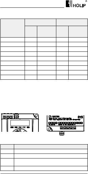
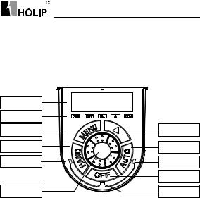
4.1 Local Control Panel
Local Control Panel (LCP)can do the operation of parameters modifications, status monitoring and drive control (start,stop), its appearance isshown blow:
Screen
Functio LED
Menu key
HAND key
HAND LED
Incremental potentiometer
Shift key
AUTO key
AUTO LED
OFF key
OFF LED
1. StateLED
The drive has three operating states: HAND control state, AUTO control state and OFF state. The operating states are indicated by HAND, AUTO and
OFF Led.
HAND LED:The drive is in the HAND control state when it is on. The f requency can be changed by turning the incremental potentiometer. Push
“HAND” key toset the drive in the HANDstate.
OFF Led:The drive is in the OFF state when it is on. Push “OFF” key to set the drive in the HANDstate.
AUTOLED:The drive is in the AUTO state when it is on. In the AUTO state, the drive is controlled by control terminals or communication. Push “AUTO” key to set the drive in the AUTO state.
2. FunctionLed
FWD, REVLed:Indicates that the drive runs forwards or reverse.
Hz, A, RPM Led:Indicates the meaning of data displayed on the screen.
Local remote running lights running lights, OFF LEDs, three LED lights indicate.
HLP-C100 Series Operating Manual |
- 25 - |
HLP-C100 Series
3. Screen
There are 5 LED which can display reference, output frequency, monitoring data and warning/alarm code.
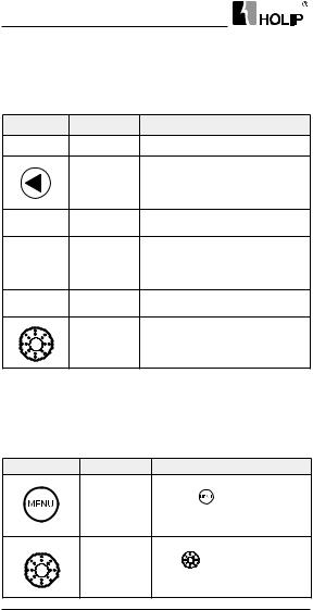
4. Keys
Symbol |
Name |
Function |
|
MENU |
Programming |
Enter or exit menu. |
|
|
|
Select the displayed parameters in |
|
|
Shift |
turn in the stop or running state; |
|
|
Select the digit to be modified when |
||
|
|
||
|
|
modifying parameters. |
|
HAND |
Hand |
Push it to set the drive in the HAND |
|
control state. |
|||
|
|
||
|
|
Stop the drive when it is in the |
|
OFF |
Off/Reset |
running state and perform thereset |
|
operation when it is in the fault |
|||
|
|
||
|
|
state. |
|
AUTO |
Auto |
Push it to set the drive in the AUTO |
|
control state. |
|||
|
|
||
|
|
Push the incremental potentiometer. |
|
|
Confirm |
Enter the menu or confirm the |
|
|
|
parameter setting. |
5. Incremental Potentiometer
Increase/decrease data or parameter, clockwise to increase, counterclockwise to decrease.
4.2 ParameterSetting
Example:Set C03.10[0]to 20.5:
Key-press |
LCP Display |
Action Description |
|
|
C00.03 |
Presskey |
to display the first |
|
basic C00.03 |
||
|
|
||
|
C03.00 |
Turn |
clockwise to select |
|
parameter groupC03 |
||
|
|
||
- 26 - |
HLP-C100 Series Operating Manual |
||
 Loading...