

Page 1

HLP-C100 Series Operating
Manual
Page 2

Introduction
Thank you for purchasing and using the minidrive of HLP-C100 series.
Please read caref ully the operation manual before putt ing the drive
to use so as to correctly install and operate the d rive, give f ull play to its
f unctions and ensu re the saf ety. Please keep the operation manual handy for
f utu re reference, maintenance, inspection and repair.
Due to the driveof a kind of powerelectronics product it must be
installed, tested a nd adjusted wit h specialized electr ical engineering workers.
Th e mar ks of
remind you of t he safety and prevention cautions dur ing the handling,
installation, running and inspection. Please follow these instr uctions to make
sure the safe use of t he drive. In case of a ny doubt please contact our local
agent f or consultation. Our professional persons are willing and ready to
ser ve you.
The ma nual is subject to change without notice.
(D ange r), (Caution)and other symbols in the manual
Page 3
HL P-C10 0 Ser ies
Index
Introduction I
Chapter 1 Sa fety Precautions - 1 -
1.1 Before Power-up -1 -
1.2 During the Power-up - 2 -
1.3 Duri ng the Operation - 3 -
1.4 After t he Power-off - 3 -
Chapter 2 Standards and Specicat ions - 4 -
2.1 Label Description - 4 -
2.2 Particular Specications - 5 -
2.3 Technical Specications - 5 -
2.4 Derat ing Specications - 7 -
2.5 Accessories - 7 -
Chapter 3 Mechanical and Electrical Installation - 8 -
3.1 Mechanical Installation - 8 -
3.1.1 Installat ion Environment Requirements - 8 -
3.1.2 External and Installation Dimensions - 8 -
3.1.3 Installation and Di rection - 9 -
3.1.4 Accessories I nstal lation - 11 -
3.2 Periphe ral Elect rical Devices - 14 -
3.2.1 Selection of MCCB/ Fuse/Contactor - 15 -
3.2.2 Selection of Braking Unit and Braking Resistor - 16 -
3.2.3 Selection of AC Input and Output Reactor - 17 -
3.2.4 Select ion of EMC Filter - 18 -
3.3 Descr iption of Mai n Circuit - 18 -
3.3.1 Schematic of Main Circuit Ter minals - 18 -
3.3.2 Main Circuit Terminal Screws and Wiri ng Recommended
Specications - 19 -
3.4 Description of Cont rol Circuit - 19 -
3.4.1 Schematic of Control Circuit Terminals - 19 -
3.4.2 Control Ter minals’ Screws and Wi ring Recommended
Specications - 20 -
3.4.3 Control Curcuit Wiring - 21 -
3.4.4 Digital Input Terminals Usage Specication - 21 -
3.5 EMC instructions - 22 -
3.5.1 Introduct ion to EMC Standard - 22 -
3.5.2 Noise Abatement - 23 -
3.5.3 Ground ing - 23 -
HLP-C100 Ser ies Operating Manual
Page 4
HL P-C10 0 Ser ies
3.5.4 Leakage Current Suppression - 23 -
3.5.5 Induction Voltage Suppression - 24 -
Chapter 4 Operation and Display Interface - 25 -
4.1 Local Control Panel - 25 -
4.2 Parameter Set ting - 26 -
4.3 FWD/REV Stat us - 28 -
4.4 Data Rea d-outs - 29 -
4.5 View Alar m Record - 30 -
4.6 View State Par ameter - 31 -
4.7 LED Display - 32 -
Chapter 5 Parameter Over view - 33 Chapter 6 Parameter Description - 43 -
6.1 Group 00: Ope ration /Display - 43 -
6.2 Group 01: Load and Motor - 45 -
6.3 Group 02: Brakes - 51 -
6.4 Group 03: Reference/Ramps - 53 -
6.5 Group 04: Limits/Warnings - 58 -
6.6 Group 05: Digital In/Out - 61 -
6.7 Group 06: Analog In/Out - 64 -
6.8 Group 07: Controllers - 67 -
6.9 Group 08: Communicat ion - 69 -
6.10 Group 14: Special Functions - 72 -
6.11 Group 15: Drive Inform ation - 76 -
6.12 Group 16: Data Readouts - 78 -
Chapter 7 Quick Application Guide - 81 -
7.1 Using LCP to Start/Stop the Drive - 81 -
7.2 Using Digital Input Terminals to Star t/Stop the Drive - 81 -
7.2.1 Two-line Mode 1 - 81 -
7.2.2 Two-line Mode 2 - 81 -
7.2.3 Th ree-line Mode 1 - 82 -
7.2.4 Th ree-li ne Mode 2 - 82 -
7.3 Multi-spee d - 83 -
7.4 Analog Input as the Frequency Source - 83 -
7.5 Speed up/down - 84 -
7.6 Parameter I nitialization - 84 -
Chapter 8 Faults and Solut ions - 85 -
8.1 Fault List - 85 -
Chapter 9 Maintenanc e - 88 -
9.1 Note - 88 -
9.2 Storage and Transpor t - 88 -
Appendix A Modbus Commun ication Specication - 89 -
Appendix B Copy Card Speci cation - 101 -
HLP-C100 Ser ies Operating Manual
Page 5
Chapter 1 Safety Precautions
HL P-C10 0 Ser ies
Caution
Danger
Indicates misu se may damage the inver ter or
mechanical system .
Indicates misuse may result in casualty.
1.1 Before Power-up
Caution
● Check to be sure that t he voltage of t he main circu it AC power
supply matches the input voltage of the d rive.
● Install the drive in a safe location, avoiding high temperat ure,
direct sunlight, humid air or wate r.
● The drive can only be used at the places accredited by our
company. Any u nauthor ized work ing envi ronment may have the
risks of re, gas explosion, electric shock and other incidents.
● If more tha n one d rive installed on the same control cabinet, make
additional cooli ng fan, so t hat the in side tempe rature is lower than
40
in order to prevent overheati ng or re occurs.
℃,
● It will affect the service life of the drive if a contactor is installed
on the input side to control the start a nd stop. Generally it is
requi red to cont rol it through terminal commands. Special
attention should be paid to its use in the case of the star t and stop
more frequently places.
● Do not install any switch component like circuit breaker or
contactor at the out put of the dr ive. If any of such components
must be installe d due process and other needs, it mu st be ensu red
that the drive has no output when the switch acts. In addition , it
is forbidden to install any capacitor for improvement of power
factor or any varistor against thunder at the out put. Otherwise
it will cause malf unctions, tripping protection and damage s of
compone nts of the dr ive.
● Please use an independent power supply for the d rive. Do avoid
using the common power supply with an electr ical welder and
other equipment with strong d isturbance. Ot herwise it will cause
the dr ive to protect or even dam age the dr ive.
● Do not make any high voltage test with any component inside the
drive. T hese semi-conductor parts are subject to the damage of
HLP-C100 Ser ies Operating Manual
- 1 -
Page 6
HL P-C10 0 Ser ies
high volt age.
● The IC board of the drive are suscept ible to the effect and damage
of static electricity. Don’t touch the mai n circuit board.
● Instal lation, commission ing and maintenance must be performed
by qualied professional per sonnel.
● Don’t carry the front cover of the d rive directly when handli ng.
It should be handled with the base t o prevent the front cover off
and avoid the d ropping of t he drive, which may possibly cause the
injur ies to people and the damages to the drive.
Danger
● Be su re to tu rn off t he power supply before wi ring.
● Mount the drive in the metal and other non-combu stible materials
to avoid the risk of re.
● Don’t install the drive in a space with explosive gas, otherwise,
they lead to explosion.
● R, S, T terminals are power input terminals, never mixed with
U.V.W term inals. Be su re that the wi ring of the main circuit is
correct. Othe rwise it will cause damages of the drive when the
power is appl ied to it.
● T he terminal of
connected toN-line. Otherw ise it will easily cause the protection
or errors of thedrive.
● Do not d issemble or modify any internal conne cting cord, wiring
or component of the dr ive by yourself.
● Never remodel it or exchange control board s a nd components by
yourself. It may expose you to an electrical shock or explosion,
etc.
● Keep the drivefrom the reach of children or pe rsons not concerned.
must be grounded separat ely and never
1.2 Duri ng the Power-up
Danger
● Do not plug the connectors of the drive during the power upto
avoid any surge into the main control board due to plugging,
which mig ht cause the damage of thedrive.
- 2 -
HLP-C100 Ser ies Operating Manual
Page 7
HL P-C10 0 Ser ies
1. 3 Dur in g t he Op era t ion
Caution
● Do not measu re the signals on circuit boards while the d rive is
run ning to avoid danger.
● The drive has been optimized before sold. Please make proper
adjust ments according to the desired functions.
● Do consider the vibration, noise and the speed limit of the motor
bearings and the mechan ical devices.
Danger
● Never connect or discon nect the motor set while thedrive is in
run ning. Otherw ise it will cause over-cu rrent t rip and even burn
up the main circuit of the drive.
● Do not come close to the machine when the ResetFunction is
used to avoid a nything unexpected. T he motor may automatically
recover f rom fault.
1.4 Af ter the Power-of f
Caution
● Even in the case of the main power, the other voltage inputs and
the share load (li nkage of DC i ntermediate ci rcuit) all have been
disconnected from the mains; the i nternal of the drive may still
have residu al energ y. Before touching any potentially live parts of
the dr ive, please wait at least 4 mi nutes. Ot herwise, it may expose
you to a risk of electrical shock.
HLP-C100 Ser ies Operating Manual
- 3 -
Page 8
HL P-C10 0 Ser ies
Chapter 2 Standards and Specications
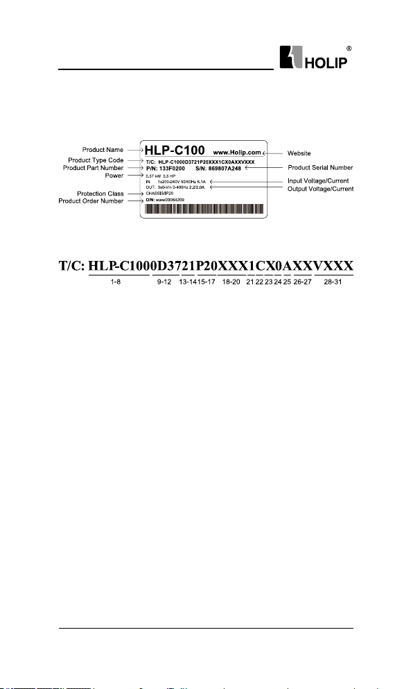
2.1 La be l Des cr iption
Signicance of the product type code:
1-8 H LP-C100 Indicate Produ ct Series
9-12 0D 37 I ndic ate 0.37KW
13-14 21 Indicate 1-Phase AC 220V
23 Indicate 3-Phase AC 220V
43 Indicate 3-Phase AC 380V
15-17 P20 IP rating is 20
18 X Without AC choke
A With AC choke
19 X Without Brake u nit
B Wit h Brake u nit
20 X Wit hout DC choke
B With DC choke
21 1 Control panel with LED display and potentiometer
22 C With coati ng on PCB
23 X R ese rved
24 0 Domestic sale
1 Overseas sale
25 A Without RS485
B Wi th RS 485
26-27 XX Re ser ved
28-31 VXX X Ind icate sof twa re version nu mber, such as
V235 means the version number is 2.35.
Note: Wit hout RS485 is sta ndard congu ration, Wit h RS485 is optional, please
specif y when ordering.
- 4 -
HLP-C100 Ser ies Operating Manual
Page 9
HL P-C10 0 Ser ies
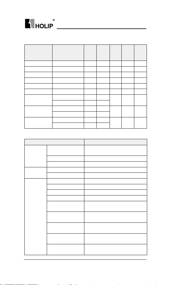
2.2 Particular Specications
Input
Output
Rated
Model
HLP-C1000D3721 1×200-240V50/60Hz 6.1 2.2 0.37 0.37 0.84
HLP-C1000D7521 1×200-240V50/60Hz 11. 6 4.2 0.75 0.75 0.8 4
HLP-C10001D521 1×200-240V50/60Hz 18.7 6.8 1. 5 1. 5 0.8 4
HLP-C1000D3723 3×200-240V50/60Hz 3. 5 2.2 0.37 0.37 0.84
HLP-C1000D7523 3×200-240V50/60Hz 6.7 4.2 0.75 0.75 0.84
HLP-C10001D523 3×200-240V50/60Hz 10. 9 6.8 1. 5 1. 5 0.84
HLP-C1000D7543
HLP-C10001D543
HLP-C10002D243
Input voltage
3×380-440V50/60Hz 3. 5 2.2
3×440-480V50/60Hz 3.0 2.1
3×380-440V50/60Hz 5.9 3.7
3×440-480V50/60Hz 5.1 3. 4
3×380-440V50/60Hz 8.5 5.3
3×440-480V50/60Hz 7.3 4.8
current/
A
current/
A
Suitable
power/
motor/
KW
KW
0.75 0.75 0.8 4
1. 5 1. 5 0.84
2.2 2.2 0.8 4
weight/
2.3 Technical Specications
Item Specication
Single/Three phase 200~240V -20%~+10%;
Th ree ph ase 380~480V -20%~ +10%;
Digi tal: 0.001Hz; A na logy: 0.5‰ of the
max. operating f requency ;
30~4000 rpm: tolerance±8 rpm;
LCP, digital ter minal, local bus;
LCP, analog, pu lse, local bus;
Selecta ble 8-speed steps ram p u p a nd
down times 0.05-300.00s;
Powe r su ppl y
Motor output
Mai n con trol
f unctions
Supply voltage
Freq uency 48~ 62Hz;
Ma x. imba lance 3%;
Output voltage Three phase 0-100% of supply voltage;
Output f requency 0- 400Hz;
Contr ol mod e V/ F, V VC+;
Sta rt torque 0.5H z 150%;
Overload ca pacity 150% 60s;
PWM switch fr equency 2 ~16 k H z;
Speed setting resolution
Speedope n-loop cont rol
accuracy
Con t r o l com m a n d
source
Frequency setting
source
Ra mp co ntr ol
Net
KG
HLP-C100 Ser ies Operating Manual
- 5 -
Page 10
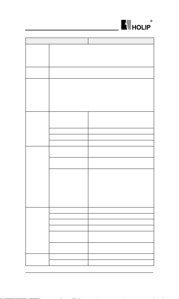
HL P-C10 0 Ser ies
Speed O pen-loop Contr ol; Process Closed-loop Contr ol; Slip
Basic
Functions
Application
Functions
Protection
Functions
Contr ol
ter minals
Display
Environment
Compensation;Torq ue compensation;Automatic Voltage Regulation;
V/F Control, DC Bra ke; Speed Li mit; Cu rren t Limi t; Flyin gSta rt;
Reset Function;
Jogging; Mu lti-speed Control via Digital inp ut; Mecha nical
Br ak ing; UP/ DOW N; Cat ch u p/Slow dow n; Cou nte r.
Missi ng Motor Phase Protect ion; Low-volta ge Protectio n; Overvoltage Protection; Over-current Protection; Output Phase Loss
Protection; Out put Short Circuit Protection; Out put G rounding
Fault Protection;Live Zero Timeout Function;ButtonFreeze;
Du plicate Fails; LCP In valid; LCP Incompa tible; Par ameter Readonl y; Reference Out of Range; Inva lid While R un ning etc.
Input
Output 1 relay output;
Powe r su pply 1 +10V, max current output 10mA;
Comm un ication* RS+, RS-, max ba ud rate 38400bit/s;
8 segments, 5 numeric
displays
Indicator
Data read-outs
Enclosure IP 20;
Ambient temperature -10℃~50℃, derating use when over 40℃;
Humidit y 5%-85% (95% wi t ho ut con de nsa tio n);
Vibr at ion test 1.14g;
Max. altitude above sea
level
Motor cable length
DC choke N on e;
others
Braking unit ≥220/380V 1.5kWBuilt-in
Item Specication
5 digi tal i n pu ts;
1an alog in put, both can receive volt age
or cu rr ent si gna ls.
Display f req uenc y, war nings, status
and so on;
Light FWD, R EV, HZ, A, RPM display
various stat us of t he drive;
Frequency setti ng, output f requency,
feedback value, output cur rent, DC
link voltage, output voltage, output
power, input terminals state, output
terminals state, analogue input ,
analogue out put, 1-10 f ault records and
accumulated working time etc.;
1000m, derating use when more t han
1000 meters;
Shield cable: 5 meter s, unshield cable: 50
me te rs;
- 6 -
HLP-C100 Ser ies Operating Manual
Page 11
HL P-C10 0 Ser ies
2.4 Derating Specications
Derating f or ambient temperature: If the drive is operated over 40℃
ambient temperature, the continuous output current should be decreased.The
drive has been designed for operation at max 50℃ ambient temperationwith
one motor size smaller than nor mal.Continuous operation at f ull load at 50
ambient temperat ion will reduce t he lifeti me of the d rive.
Derating f or low air pressure: The cooling capability of air is decreased
at low air pressure. Below 1000m altitude no de-rating is necessar y but above
1000m the ambient temperature or the maximum output current should be
decreased. Dcrease the output by 1% per 100m altitude above 1000m or red uce
the max. a mbient t emperat ure by 1 degree per 200m.
℃
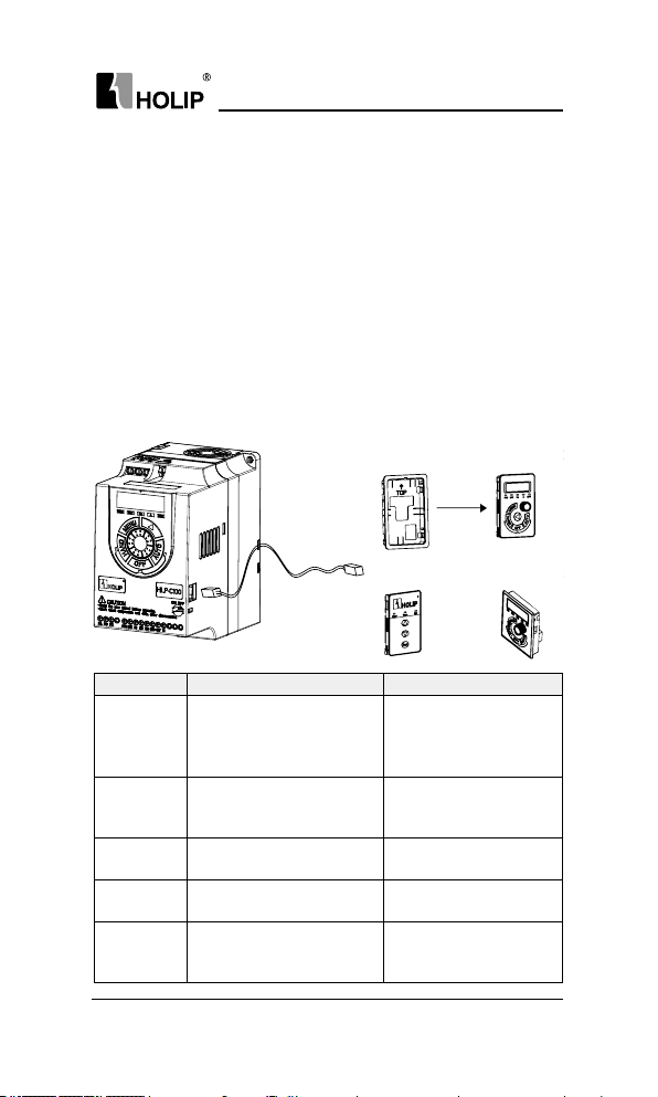
2.5 Accessories
C r ad l e - 01
Network Cable
CopyCard-01 LCP-03
Model Specication Remark
LCP-02
LCP-03
C r ad l e - 01 For LCP-02 installation.
CopyCard-01
Network
Cable
The standard length of
extension cable is 15 meters
when mounting LCP on control
cabi net.
LCP-03 has t he same installat ion
dimensions wit h HLP-A control
panel (OP-AB01).
Copy Card can copy parameters
f rom one drive to another.
Connect LCP to t he drive when
mounti ng LCP on control
cabi net.
HLP-C100 Ser ies Operating Manual
Op t iona l, ple ase s pecif y
when ordering
Op t iona l, ple ase s pecif y
when ordering
Op t iona l, ple ase s pecif y
when ordering
Op t iona l, ple ase s pecif y
when ordering
Do not of fer, self
procu reme nt
LCP-02
- 7 -
Page 12
HL P-C10 0 Ser ies
Chapter 3 Mechanical and Electrical Installation
3.1 Mechanical Installation
3.1.1 Installat ion Environment Requirements
1 Ambient temperature in the range of -10℃~ 50℃;
2 Drive should be in stalled on surfa ce of fla me retardant object, with
adequate sur roundi ngspace for heat dissipation;
3 Installation should be per formed where vibration is less t han 1.14g;
4 Avoid from moisture and direct su nlight;
5 Do not expose to a n atmosphere w ith fla mmable gases, corrosive
gases, explosive gasesor other harmf ul gases;
6 Protect the cooli ng fan by avoiding oil, dust a nd metal particles;
7 Prevent d rilling residues, wire ends and screws falli ng into drive;
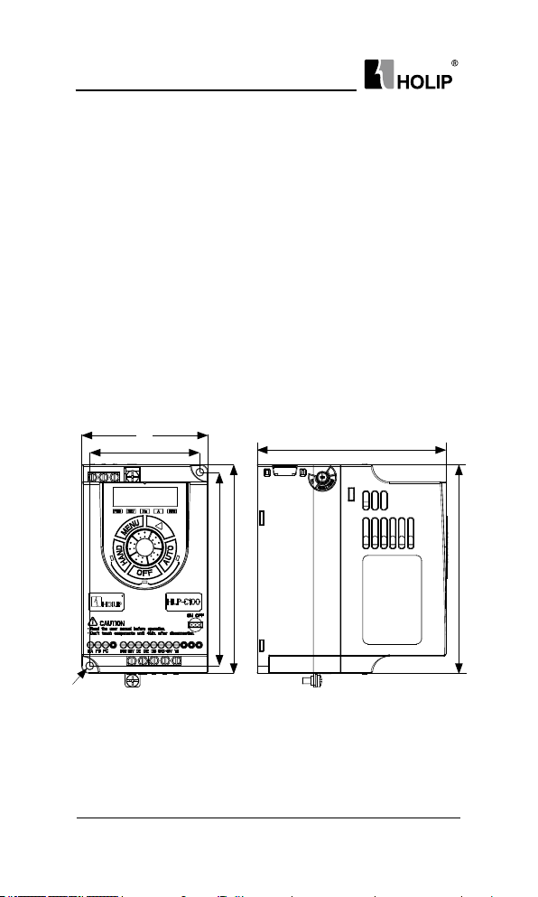
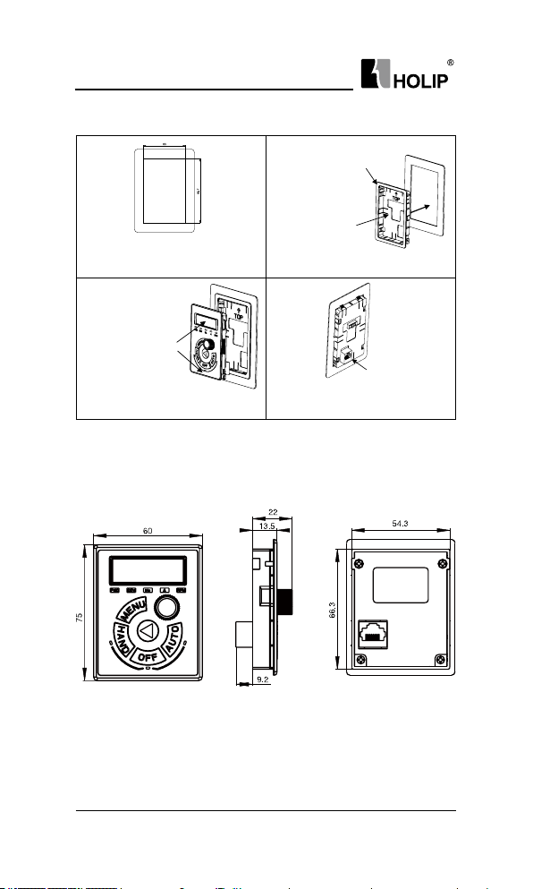
3.1.2 External and Instal lation Dimensions
B
A
CFD D
Single/t hree phase 220V 0.37~1.5kW and thre e phase 380V 0.75~2.2kW
- 8 -
HLP-C100 Ser ies Operating Manual
E
Page 13
HL P-C10 0 Ser ies
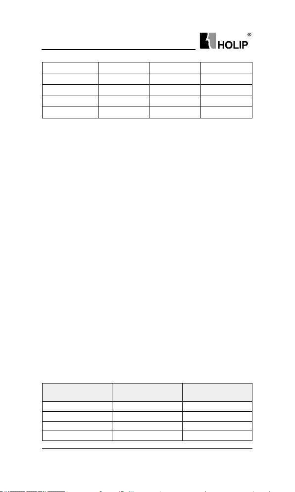
Exter nal and installation dimensions(unit: mm)
Model A B C D E F
HLP-C1000D3721
HLP-C1000D7521
HL P-C10 001D521
HLP-C1000D3723
HLP-C1000D7523
HL P-C10 001D523
HLP-C1000D7543
HL P-C10 001D543
HLP-C10002D243
74 85 130 140 127 5
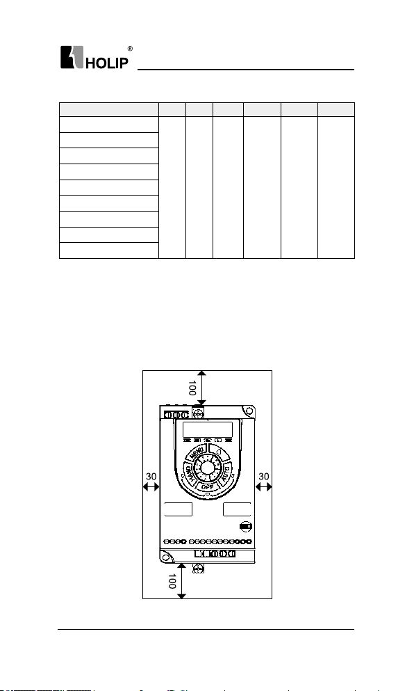
3.1.3 Installation and Direction
1. Single Installation
The dr ive must be in stalled vertically with smooth ventilation. Enough
space must be left around the drive to ensure good cooling, as show n
below (unit: m m):
HLP-C100 Ser ies Operating Manual
- 9 -
Page 14
HL P-C10 0 Ser ies
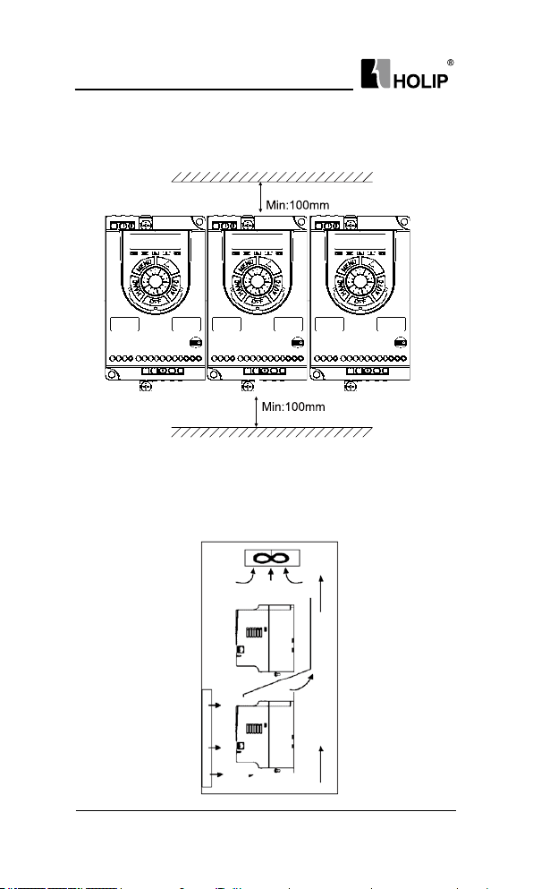
2. Side by Side Installation
The dr ive can be mou nted side by side, a minimum space must be
reser ved above and below the enclosu re, as show n below:
3.Upper and Lower Installation
If several drives need to be in stalled together i n one cabinet, upper a nd
lower installation can be adopted. Enough space mu st be reserved to
ensure effective cooling, as shown below:
- 10 -
HLP-C100 Ser ies Operating Manual
Page 15

HL P-C10 0 Ser ies
59.5
21.7
57.1
12.8
13.3
92.6
89.2
3.1.4 Accessories Installation
1. LCP-02 Installation
The external dimension s of LCP-02 are shown below (unit: mm):
When i nstalling LCP-02 outside, a cr adle is needed. The external
dimensions of the cr adle are shown below (unit: mm):
HLP-C100 Ser ies Operating Manual
- 11 -
Page 16
HL P-C10 0 Ser ies
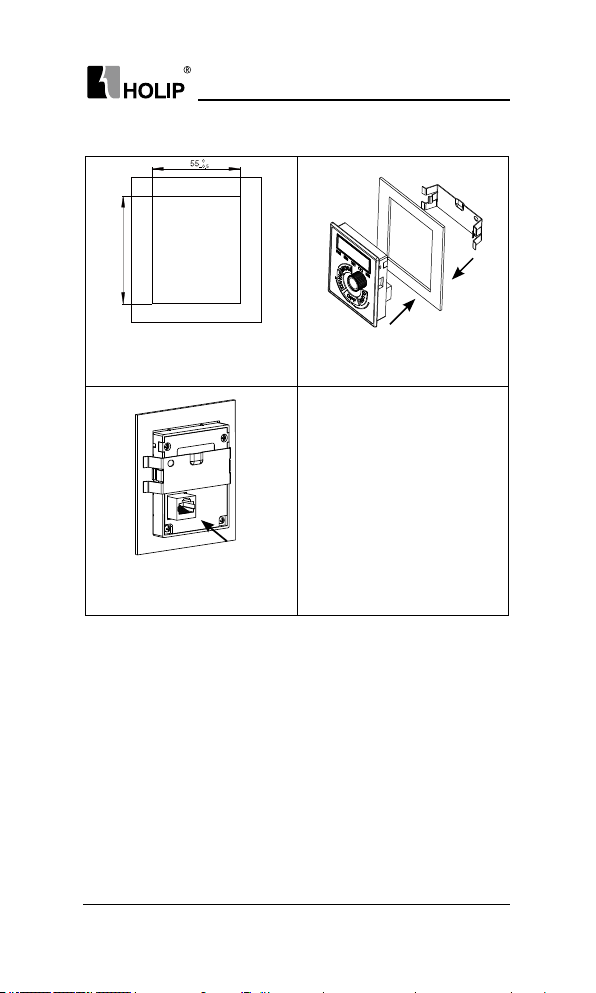
The installat ion steps of LCP-02 are shown below:
Th is cra dle is sui ta ble f or 1.0 -2.0m m
th ickness s heet
meta l par ts
Press and hold
the snap roots whe n
installation, using
buckle deformation
Step1: Open a hole i n line with the size of
the con trol pa nel in t he position need to
install t he LCP, hole size, as shown:
Recommen ded
to install ver tical
mounti ng position
arrow, press with
unif orm for ce.
Step 3: The LCP is installed in the cr adle,
according to the dir ection of the arrow.
install sheet metal.
Step2: Install the LCP according to
the di rection of t he arrow.
Step 4: Install the external LCP communication
cable, insert into RJ45 ter minal from thebottom
of hole.
2. LCP-03 Installation
The external dimension s of LCP-03 are shown below (unit: mm):
- 12 -
HLP-C100 Ser ies Operating Manual
Page 17
The installat ion steps of LCP-03 are show n below:
Ste p 1: Open a h ole i n th e co ntrol pane l
where it is needed to ins tall LCP-01 or
LCP-02, the hole size is as shown.
Step 3: Inst all the LCP com mun-ication
cable, insert into RJ45 terminal f rom the
bot tom hole.
HL P-C10 0 Ser ies
HLP-C100 Ser ies Operating Manual
- 13 -
Page 18
HL P-C10 0 Ser ies
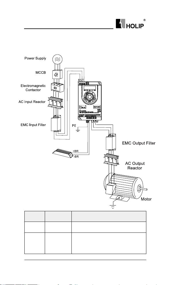
3.2 Peripheral Electrical Devices
The per ipheral electrical devices of the drive a re shown below:
Part
MCCB
Contactor
- 14 -
Mounting
Location
Power
receiving side
Between
MCCB and
drive i nput
side
HLP-C100 Ser ies Operating Manual
Inter rupt t he power supply when
overcurrent occurs ondownstream devices.
Do not sta rt and st op the dr ive frequently
by switch ingthe contactor on and off (less
than t wice per m inute) noruse it to directly
star t the dr ive.
Function Description
Page 19
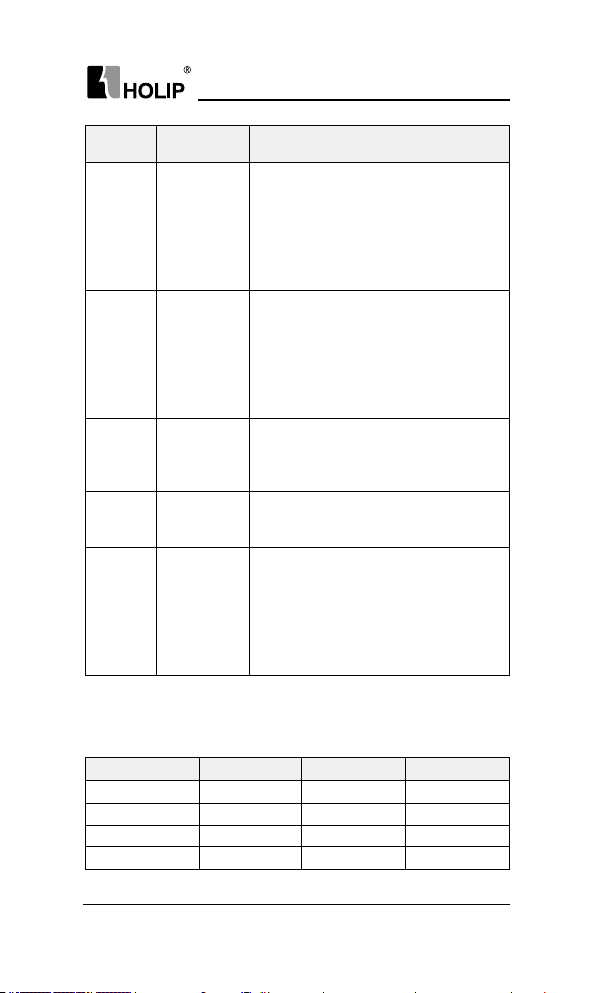
HL P-C10 0 Ser ies
Part
AC input
reactor
EMC input
lter
Braking
unit
Braking
resistor
EMC
output
lter
AC output
reactor
Mounting
Location
Drive input
side
Drive input
side
≥1.5kW
Braking unit
is standard
conguration
Drive out put
side
Betwee n the
drive
output side and
the
motor, close to
the
drive
Function Description
Improve the power factor of the input side;
Elimi nate the i nput cur rent unbalance due
to unbalancebet ween the power phases;
Elimi nate the h igher harmonics of the input
sideeffectively;
prevent ot her device s from bei ngdamaged
due to distortion of the voltage wavefor m;
Decrease the conduction interference
owing f rom the power e nd to the drive and
improve the antiinterference capacity of the
drive;
Reduce the exter nal conduction and
radiation
inter ference of the drive;
Consu me the motor feedback energy to
achieve rapid braking.
Reduce the exter nal conduction and
radiation
inter ference of the drive.
Degra de the motor insulation performance
and damage the motor in the long r un;
Generate large leakage current and cause
frequent ACdrive protection trips;
If the distance between the drive and the
motor isg reater than 100 m, install an AC
output reactor;
3.2.1 Selection of MCCB/Fuse/Contactor
Model MCCB (A) F use (A) Cont actor (A)
HLP-C1000D3721 10 10 10
HLP-C1000D7521 25 25 16
HL P-C10 001D521 32 32 25
HLP-C1000D3723 10 10 10
HLP-C100 Ser ies Operating Manual
- 15 -
Page 20
HL P-C10 0 Ser ies
HLP-C1000D7523 16 16 10
HL P-C10 001D523 25 25 16
HLP-C1000D7543 10 10 10
HL P-C10 001D543 10 10 10
HLP-C10002D243 16 16 10
3.2.2 Selection of Braking Unit and Braking Resistor
Users can select different braking resistor for different applicat ion,
it is calculated as follows. But the resistance should not be less than the
minimum recommended in the table, otherwise there is a risk of da mage
cau sed by the d rive, the p ower of brakin g resistor can b e greate r.the
gre ater system ine rtia, the shor t deceleration t ime , the more freque nt
bra king, the greater the power of the brak ing resistor, the sm alle r the
braking resistor value.
1. Selection of the Braki ng resistor value
The bra king resistor value:R = U
is the limit of the DC bus, generally it is 700V for 400V model ,
U
DH
400V for 200V model.
is rated motor power
P
MN
is br aking torqu e coefficient, it i s bet ween 0.8 to 2 .0. For
K
B
general machine, it is 1.0, for greateriner tia mach ine, it is 1.5 to 2.
;
DH×UDH
÷(KB×PMN)
2. Selection of the Braki ng resistor power
Braking power: Pb = U
Th eor et ica lly b ra ki ng resi sto r pow er and br ak ing powe r ca n
DH×UDH
÷ R
be t he same, Bu t in a ct ua l cho ice, it w il l be mult iplie d by a
correction factor, braking resistor power
Pr = a Pb
correction factor: a = 0.12~ 0.9
For not frequent accele ration and deceleration application, a can
be set as 0.12, for
frequent ac celeration and deceleration a pplication, it should be
increased.
3. Recommended selection
Model
Braking resistor
Recom mended Power
Braking resistor
Recommended value
HL P-C10 001D521 300W
HL P-C10 001D523 300W
HL P-C10 001D543 250W
HLP-C10002D243 500W
- 16 -
HLP-C100 Ser ies Operating Manual
≧
≧
≧
≧
50Ω
50Ω
200Ω
100 Ω
Page 21

HL P-C10 0 Ser ies
For the power less t han 0.75kW (including) models, the selection of
braking resistor depends on the selection of braking un it.
3.2.3 Selection of AC Input and Output Reactor
1. The guide of AC input reactor selection
Model
HLP-C1000D3721 6 9 11.6 4
HLP-C1000D7521 12 18 5.74
HL P-C10 001D521 19 28.5 2.87
HLP-C1000D3723 3.5 5.2 11.6 4
HLP-C1000D7523 7 10. 5 5.74
HL P-C10 001D523 11 16 .5 2.87
HLP-C1000D7543 3.5 5.2 16
HL P-C10 001D543 6 9 8
HLP-C10002D243 8.5 13 5.5
2. the guide of AC output reactor selection
Model
HLP-C1000D3721 2.5 5.3 9.78
HLP-C1000D7521 5 10.6 4.82
HL P-C10 001D521 7. 5 15.9 2. 41
HLP-C1000D3723 2.5 5.3 9.78
HLP-C1000D7523 5 10.6 4.82
HL P-C10 001D523 7. 5 15.9 2. 41
HLP-C1000D7543 2.3 4.8 14.39
HL P-C10 001D543 4 8.5 7.19
HLP-C10002D243 5.6 11 .9 4.9
Ratedcurrent
(A)
Rated current
(A)
Maximum
continuous
current(A)
Saturation
current (A)
Inductance (mH)
& 3% Impedance
Inductance (mH)
& 3% Impedance
HLP-C100 Ser ies Operating Manual
- 17 -
Page 22
HL P-C10 0 Ser ies
3.2.4 Selection of EMC Fi lter
EMC Input Filter EMC Output Filter
Model
HLP-C1000D3721 10 NFI- 010 5 NFO-005
HLP-C1000D7521 20 NFI-020 5 NFO-0 05
HL P-C10 001D521 20 NFI-020 10 NFO- 010
HLP-C1000D3723 5 NFI-005 5 NFO-005
HLP-C1000D7523 10 NF I- 010 5 NFO-005
HL P-C10 001D523 10 NF I- 010 10 N FO- 010
HLP-C1000D7543 5 NFI-005 5 NFO-005
HL P-C10 001D543 5 NFI-005 5 NFO-005
HLP-C10002D243 10 NFI- 010 10 N FO-010
* Recommended models is the Shanghai Eagtop Electronic Technology Co.,
Ltd. products, website:http://www.eagtop.com/
Rated
Current
(A)
Recommended
Model*
Rated
Current
(A)
Recommended
Model*
3.3 Description of Main Circuit
3.3.1 Schematic of Main Circuit Terminals
R S T PE
+BR-BR
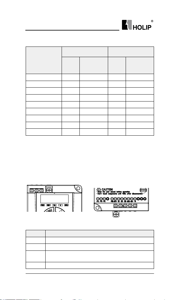
Descr iption of mai n circuit terminals:
Symbol Function
R, S, T Power input, Single phase con nected to R, T
U, V, W Power output, connect t o the motor
+BR, -BR
PE Ground ter minal
- 18 -
Connect the brake resistor, make sure to set C02.10, C02.11
etc.
HLP-C100 Ser ies Operating Manual
PE
u v w
Page 23
HL P-C10 0 Ser ies
3.3.2 Main Circuit Terminal Screws and Wiring Recommended
Specications
Input and
Model
Input
Cable
(mm
Output
2
)
Cable
(mm
Te r mi na ls’
2
)
Output
Screws
Input and
Output
Te r mi na ls’
Torq ue
Ground
Te r m i nal
Screw
Ground
Te r m i nal
Torq ue
HLP-C1000D3721 1 1 M3.5 0.8 -1.0 M4 1.0-1. 2
HLP-C1000D7521 1.5 1 M3.5 0.8-1.0 M4 1.0-1. 2
HL P-C10 001D521 1. 5 1 M3.5 0 .8-1. 0 M4 1.0 -1.2
HLP-C1000D3723 1 1 M3.5 0.8-1.0 M4 1.0 -1.2
HLP-C1000D7523 1 1 M3.5 0.8-1.0 M4 1.0 -1.2
HL P-C10 001D523 1. 5 1 M3.5 0.8 -1.0 M4 1.0-1. 2
HLP-C1000D7543 1 1 M3.5 0.8-1.0 M4 1.0 -1.2
HL P-C10 001D543 1 1 M3.5 0.8-1.0 M4 1.0 -1.2
HLP-C10002D243 1 1 M3.5 0.8-1.0 M4 1.0 -1.2
Note: This specif ication is under using single-core line VV and 25℃, if use
other cables or under higher temperat ure environment, please refer to
electr ical manual.
3.4 Description of Control Circuit
3.4.1 Schematic of ControlCircuit Terminals
FA FB FC FOR FE V D11 D12 D13 GND +10V VI RS+ RS- COM
Terminals’ specication:
Symbol Descr ipt ion Specication
1. Resistive L oad: 250VAC 3A/30VDC
FA-FB-FC Relay output
FOR, REV,
DI1, DI2, DI3
Digital in put
3A;
2 . I n d u c t i v e L oa d : 2 50 VA C
0.2A/2 4V DC 0.1A (co sφ =0.4);
FA-FB: NC, F B-FC: NO
1. L og i c:
>DC 19V Logic:0;
<DC 14V Logic: 1;
2. Voltage: DC0~24v;
3. Input resistance: 5kΩ;
4. Inp ut volta ge Rang:Max ±30v;
J1
HLP-C100 Ser ies Operating Manual
- 19 -
Page 24
HL P-C10 0 Ser ies
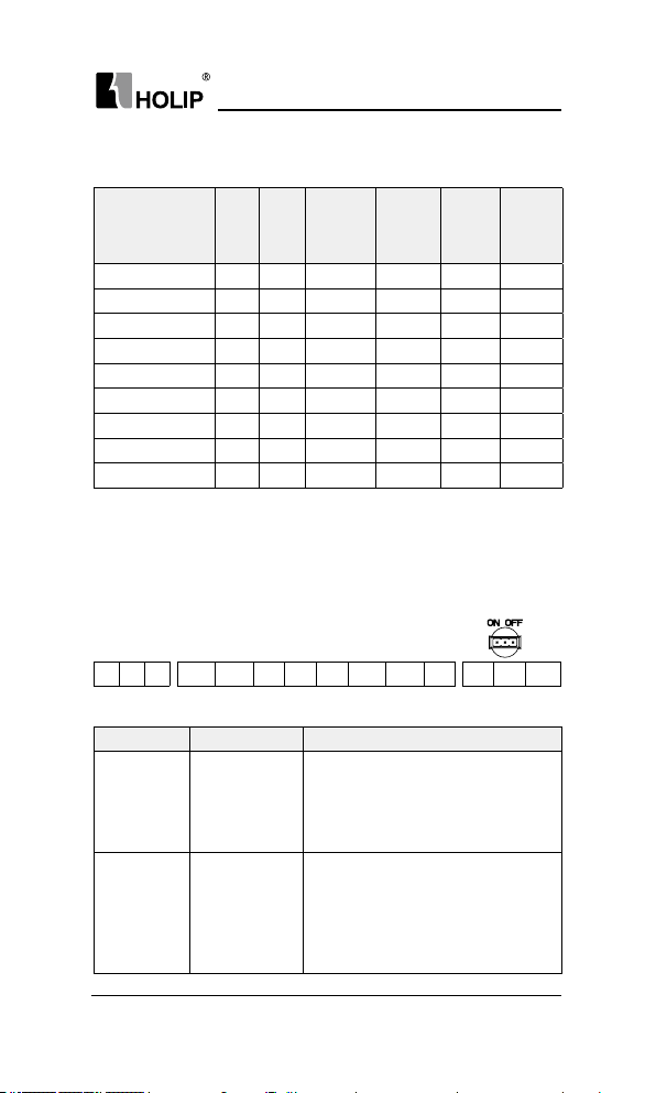
ON
OFF
1 2 3
GND Digital/Analog Isolated f rom i nter nal COM.
+10 V 10Vpower supply
VI An alog i nput
J1
RS 485
communication
RS 485
termination
resisto r ju m per
switch
RS+, RS-
COM Digita l ground Isolated f rom internal GN D;
Maxload 10m A, wit h over load and
short circuit protection functions.
VI can be configurated to 0-20mA or
0-10Vby paramters:
1. Input Impedance: about 10kΩ;
2. Inpu t Impedence: ≤500Ω;
Max baud rate: 38400bit/s;
Jum per switch 1-2 connected: ON,
ter mination resistor con nected;
Ju mpe r sw it ch 2-3 connec ted: OFF,
termination resistor not connected,
default state;
3.4.2 ControlTerminals’Screws and Wiring Recommended
Specications
Cable ty pes
Shielded cables 0.4 0.4
Cable specications
(mm
2
)
Tor que (n∙m)
- 20 -
HLP-C100 Ser ies Operating Manual
Page 25
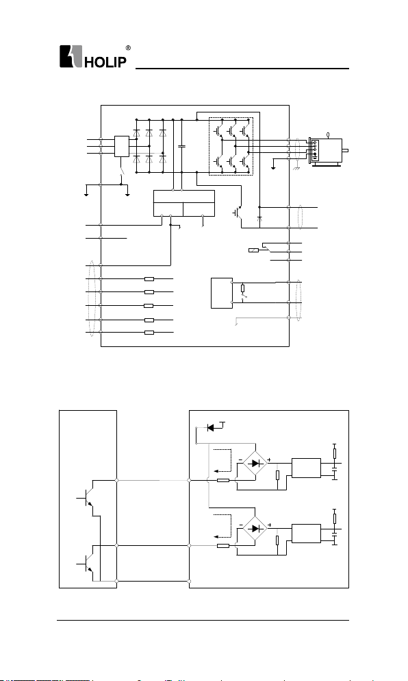
3.4.3 ControlCurcuit Wiring
Switch Mode
Power Supply
10VDC
10mA
24VDC
200mA
RS485
Interface
PE
R
T
S
Power
Supply
U
V
W
PE
+10V
VI
GND
FOR
REV
DI1
DI3
DI2
+BR
-BR
FA
FB
FC
RS+
RS-
COM
0-10V
/4-20mA
Braking
Resistor
RS485
Communication
Relay
Motor
RFI
RFI
Switch
Digital
Input
Terminal
Resistor
Jumper
Switch J1
24V (NPN)
24V (NPN)
24V (NPN)
24V (NPN)
24V (NPN)
2
3
1
Opto-
isolator
+24V
+3.3V
GND
Opto-
isolator
+3.3V
GND
DI1
DIn
GND
Drive
Y1
Yn
External
Controller
3.4.4 Digital Input Terminals UsageSpecication
Open collector NPN mode wiring
HL P-C10 0 Ser ies
HLP-C100 only supports this mode.
HLP-C100 Ser ies Operating Manual
- 21 -
Page 26

HL P-C10 0 Ser ies
3.5 EMC instructions
3.5.1 Introduction to EMC Standard
The HLP-C100 series satises t he requirements of stand ard IEC/E N61800-3:
2004 (Ad justable speed elect ricalpower drive systems part 3:EMC requirements
and specic test methods).
3.5.2 Noise Abatement
1. When peripheral equipment and the drive share the power supply
of one system, noise from the drive may be tra nsmitted to other
equipment in this system via power lines a nd result i n misoperation
and/or faults. In such a case, the following mea sures could be take n:
Mount input noise lter at input terminal of the drive;
a.
b. Mount power supply lter at power input terminal of af fected
equipment;
c. Use isolation t ra nsform er t o isolate the n oise tr ansmission path
2. As the wiring of peripheral equipment and the drive constitutes a
3. Sensitive equ ipment and sig nal lines shall be mounted as far away
4. Sig nal lines should be provided with shielded layer and reliably
5. Signal lines must orthogonally cross power lines if this cross
6. Motor cables shall be placed in thick protective screen like more than
7. Use 4 -core motor cables of which one is grou nded at close side of t he
8. I nput and out put ter minals of drive are respectively equippe d with
between other equipment and the drive.
circuit, the unavoidable ear thing leakage current of drive will cause
equipment misoperation and/or faults. Disconnect the grounding
connection of equipment may avoid th is misoperation a nd/or faults.
from drive as possible.
grounded. Alternatively, signal cable could be put into metallic
conduit s between which the distance shall be no less than 20c m, and
shall be kept as far away f rom drive and its per ipheral devices, cables
as possible. Never make signal lines in parallel with power li nes or
bundle t hem up.
inevitable.
2mm-t hick pipeli nes or bur ied cement groove, also, power lines can
be put into metallic conduit and grounded well with sh ielded cables.
drive and the other side is connected to motor enclosu re.
radio noise lter and linear noise lter. For example, ferrite common
mode choke ca n restr ain rad iation noise of power lines.
- 22 -
HLP-C100 Ser ies Operating Manual
Page 27
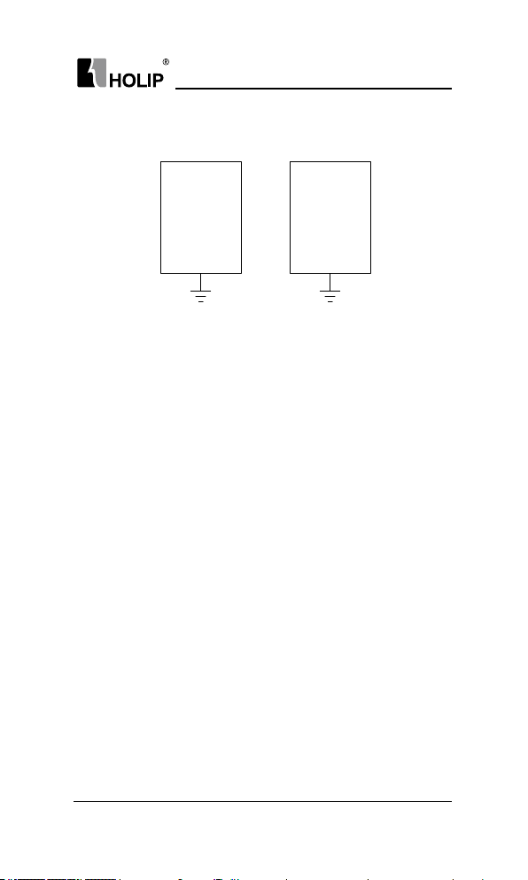
3.5.3 Grounding
Drive
Other
Devices
PE PE
Recommended ground electrode is shown in the gure below:
1. Use to the fullest extent the maxi mum standard size of grounding
cables to reduce the impedance of grounding system;
2. Grounding w ires should be as shor t as possible;
3. Grounding p oint shall be as close to the drive as possible;
4. One wire of 4 -core motor cables shall be grounded at the d rive side
and con nected to ground ing ter minal of motor at the other side.
Bette r effect will be achieved if motor and drive are provided with
dedicated ground electrodes;
5. When groundi ng termi nals of various parts of system are linked
togethe r, leakage current tu rns i nto a noise source that may inuence
other equipment in the system, thus, g roundi ng terminals of the drive
and othe r vulnerable equipment should be separated;
6. Grounding cable shall be kept away from input& output of noise-
sensitive equipment.
3.5.4 Leakage Current Suppression
Leakage current passes th rough the line-to-line and ground distributed
capacitors at input & output sides of drive, and its size is associated with the
capacitance of distributed capacitor and the carrier f requency. Leakage cur rent
is classied into grou nd leakage cu rrent and line-to-line leakage curr ent.
1. Ground leakage current not only circulates inside drive syst em, but
may also inuence other equipment via ground loop. Such a leakage
current may result in malf unction of RCD and other equipment.
The higher the car rier f requency of drive is, the bigger the g round
leakage current would be. The longer the motor cables and t he bigger
the par asitic capacitance are, the bigger the ground leakage current
would be. Therefore, the most immediate and effective method for
suppre ssion of grou nd leakage curre nt is to reduce carr ier frequency
HLP-C100 Ser ies Operating Manual
HL P-C10 0 Ser ies
- 23 -
Page 28

HL P-C10 0 Ser ies
and minimize the length of motor cables.
2. The h igher harmonics of line-to-line leakage cu rrent t hat passes
through between cables at out put side of dr ive will accel the aging
of cables and m ay bring about malf unction of other equipment. The
higher the carrier frequency of drive is, the bigger the line-to-line
leakage current would be. The longer the motor cables and t he bigger
the par asitic capacitance are, the big ger the line-to-line leakage
current would be. T herefore, the most immediate and effective
method for suppression of ground le akage cu rrent is to reduce
carrier requency and mi nimize the length of motor cable. Line-toline lea kage current can also be effectively suppressed by mou nting
additional output reactors.
3. For the HLP-C100 serials, it can remove RFI screw t o cut RFI lter
to reduce the leakage current;
3.5.5 Induction VoltageSuppression
The dr ive outpu ts pulse voltage which w ill for m induction voltage in t he
surface of the motor when the dr ive is not grounded. The induction voltage
can be reduced by connecting the drive's PE terminal to the motor and closing
RF I screws .
- 24 -
HLP-C100 Ser ies Operating Manual
Page 29
HL P-C10 0 Ser ies
Chapter 4 Operation and Display Interface
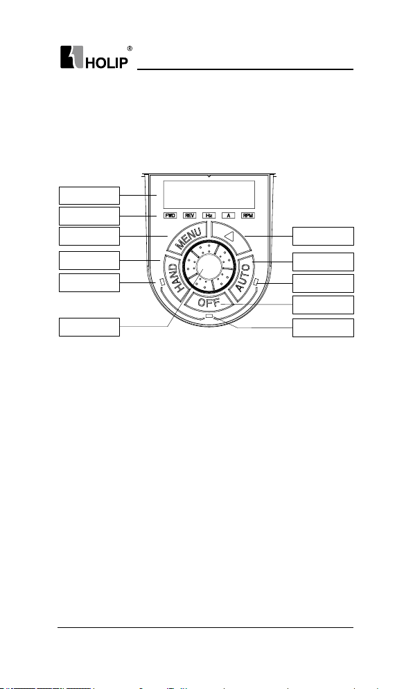
4.1 Local Control Panel
Local Control Panel (LCP)can do the operat ion of paramet ers mod icat ions,
stat us monitori ng and dr ive control (sta rt, stop), its appearance is shown blow:
Screen
Functio LED
Menu key
Shift key
HAND key
HAND LE D
Incremental
potentiometer
AUTO key
AUTO LED
OFF key
OFF LED
1. StateLED
The drive has th ree operating states: HAND control state, AUTO cont rol
state and OFF sta te. The operating states are indicated by HA ND, AUTO and
OFF Led.
H A ND LE D: The drive is in the HA ND cont rol st ate w hen it is on. The
f requency can be changed by turning the incremental potentiometer. Push
“HA ND” key to set the drive in the HA ND state.
OF F Led: The drive is in the OFF state when it is on. Push “OFF” key to set
the dr ive in the HA ND state.
AU TO LE D: The d rive is in t he AUTO state when it is on. In the AUTO state,
the d rive is controlled by control termi nals or communication. Push “AUTO”
key to set the d rive in the AUTO state.
2. FunctionLed
FWD, REVLed: Indicates that the dr ive runs forwa rds or reverse.
Hz, A, RPM Led: Indicates the meaning of data displayed on the screen.
Local remote r un ni ng lig hts ru nning ligh ts, OFF LEDs, t hree LED lights
in dica te.
HLP-C100 Ser ies Operating Manual
- 25 -
Page 30
HL P-C10 0 Ser ies
3. Screen
There are 5 LED which can display reference, out put f requency,
monitoring data and warning/alarm code.
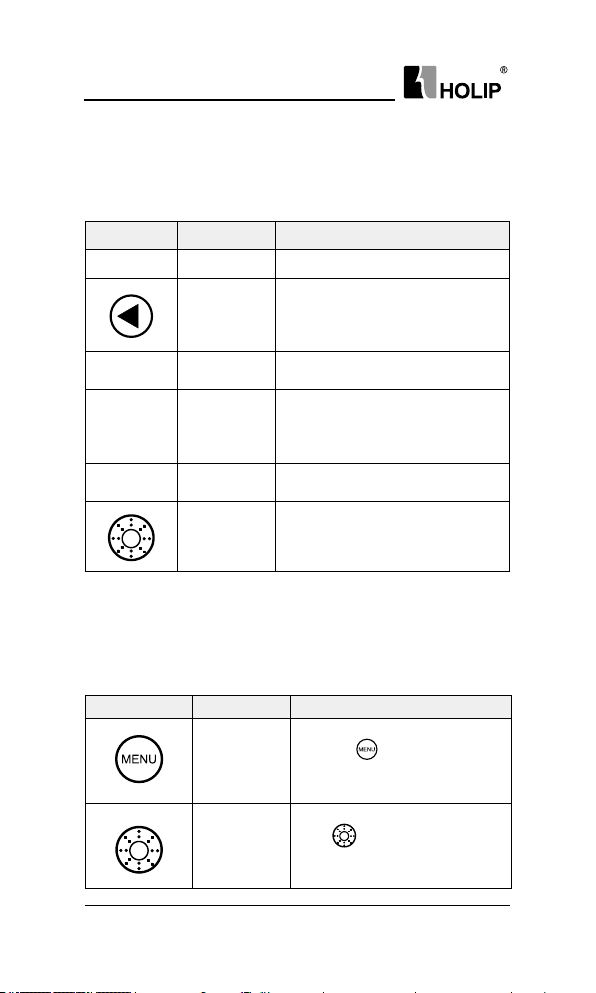
4. Keys
Symbol Name Function
MENU Programming Enter or exit menu.
Select the displayed pa ramete rs in
Shift
HAND Hand
OFF Off/Reset
AUTO Auto
Conrm
5. Incremental Potentiometer
Inc rease/decrease dat a or pa ra meter, clockwise to inc rease, cou nte rclockwise to decr ease.
tur n in the stop or running state;
Select the digit to be modied when
modifying parameters.
Push it to set the dr ive in the HAND
control state.
Stop the d rive when it is in the
run ning st ate and pe rform thereset
operation when it is in the fault
state.
Push it to set the dr ive in the AUTO
control state.
Push the incremental potentiometer.
Enter the menu or conrm the
parameter setting.
4.2 ParameterSetting
Example:Set C03.10 [0] to 20.5:
Key-press LCP Display Action Descr iption
- 26 -
C00.03
C03.00
HLP-C100 Ser ies Operating Manual
Presskey
basic C0 0.03
Turn
parameter groupC03
to display the rst
clockwise to select
Page 31

C03.00
C03.10
[0]
0000
000.5
000.5
020.5
HL P-C10 0 Ser ies
Press
key to shift to fractional
part
Turn
clockwise to select
parameterC03.10
Press
key show the rst
option of C03.10
key to show the value
Press
of the rst option of par ameter
C03.10
Turn
clockwise to change the
fractional part to 5
Press
key to shift to integral
part
Press
key to change the
integral par t to 20
Press
END
HLP-C100 Ser ies Operating Manual
key to accept the
change and save it as 20.5
- 27 -
Page 32

HL P-C10 0 Ser ies
4.3 FWD/REV Status
Conr m t he direct ion of the motor according to the set value, as shown in
t he f ollo wi ng t a ble:
Reference: R unning stat us Indicator Display
≥0 STOP
0 STOP
<
≥0 FWD
≥0 REV
0 FWD
<
0 REV
<
Note: A ash light denotes the stat us coming, Ligh t o n i ndica tes the cu rrent
state, and light of f means not in this state.
Example 1: The f irst line of the table indicates the drive is stop and the
reference is greater than or equal to 0, means the dir ve at some time in
the f uture will ru n for ward.
Example 2: The fou rt h line of t he table represents the cur rent d rive is reverse
ru nni ng, and the reference setting is greater than or eq ual to 0, it means
the d rive at some ti me in the f utu re will r un f orward.
- 28 -
HLP-C100 Ser ies Operating Manual
Page 33
HL P-C10 0 Ser ies
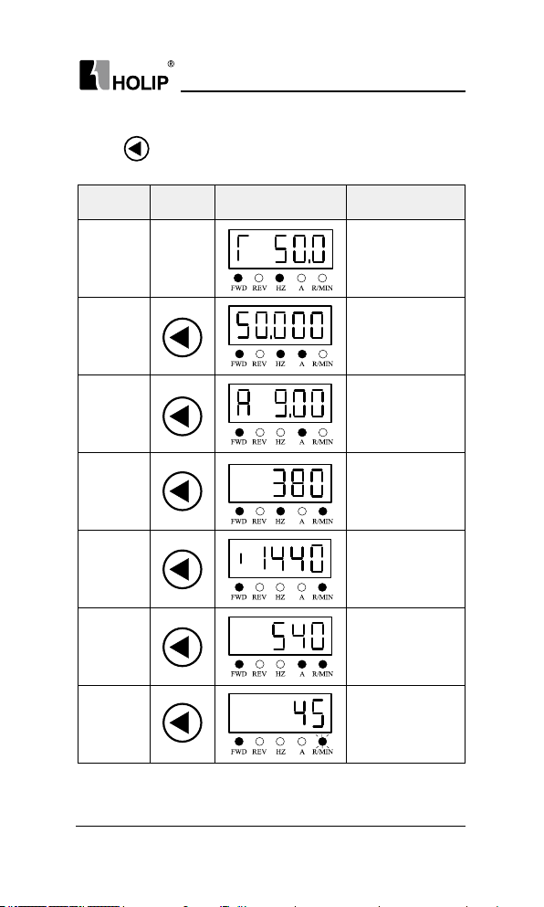
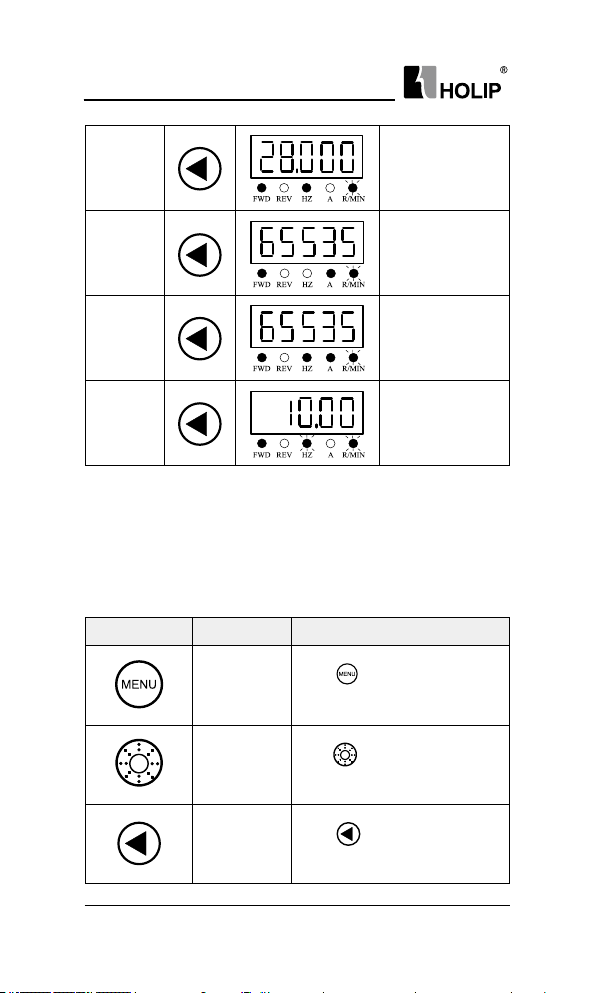
4.4 Data Read-outs
Press key to change the display items on LCP while displaying out put
f req ue ncy.
Display
Items
Output
Frequency
Reference
Motor
Current
Motor
Vol ta ge
Motor
Speed
DC Voltage
Drive
temperatu re
Key-press LCP Display Action Description
Show the out put
Initial
interface
frequency
C16.13is 50. 0H z,
display accuracy: 0.1
Show the reference
C16.01 is 50.00 0,
display accuracy:
0.0 01
Show the motor
cu r re nt C16.14
is 9.00A, display
accuracy: 0.01
Show the motor
voltage C16.12
is 380V, display
accuracy: 1
Show the motor
speed C16.05 is
1440rpm, display
accuracy:1
Show the DC
Voltage C16.30is
540V,display
accuracy: 1
Show the
drive temperature
C16.34 is45℃,
display accuracy:1
HLP-C100 Ser ies Operating Manual
- 29 -
Page 34
HL P-C10 0 Ser ies
Feedback
Val ue
Counter A
Counter B
Analog i n
VI
Note: The drive only monitor output f requency, reference and output cur rent
reference by default. For monitoring other status (DC voltage, etc.),
please set the parameter C00.33 (refer to inst ructions).
Show the feedback
value C16.52
is28.000, display
accuracy: 0.001
Show counter A
C16.72 is 65535,
display accuracy:1
Show counter B
C16.72 is 65535,
diaplay accuracy: 1
Show analog i n VI
C16.62 is10.00V,
display accuracy:
0.01
4.5 View Alarm Record
If the drive trips, fault code will be showed to illustra te the reason,the drive
will save the last 10 trip record.
Key-press LCP Display Action Description
Press
C00.04
key to display the rst
basic C0 0.04.
- 30 -
Turn
C15.00
C15.00
HLP-C100 Ser ies Operating Manual
clockwise to select par.
group No.C15.
Press
to select parameter
num ber.
Page 35
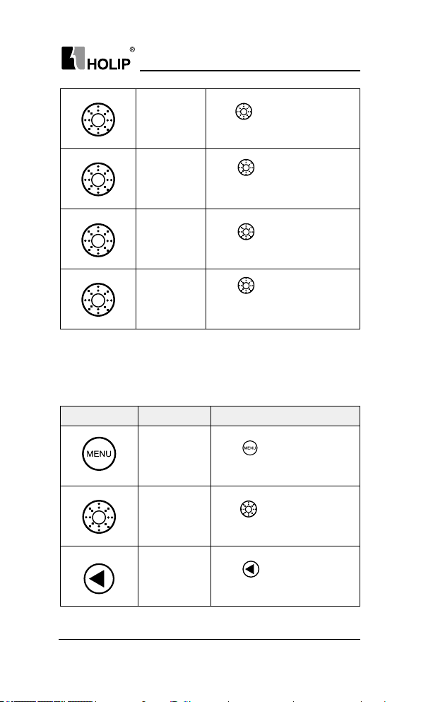
HL P-C10 0 Ser ies
Turn
C15.30
[0]
**
[1]
clockwise to select
C15.30
Press
to show the rst option
of C15.30
Press
to show the rst fault
record.
Press
to show the second
fault record, it can d isplay up to
ten recent fault records in t urn.
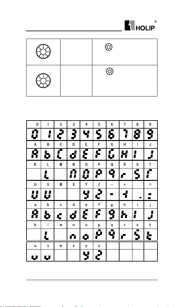
4.6 View State Parameter
By viewing the group 16th parameters can lear n t he cur rent sta tus of the
drive. For example: C16.60 indicators the current state of digital input terminals.
Key-press LCP Display Action Description
Press
C00.04
to display the rst
basic parameterC00.04.
Turn
C16. 00
C16. 00
HLP-C100 Ser ies Operating Manual
clockwise to select
Par. group No. C16
Press
to select parameter
No.
- 31 -
Page 36
HL P-C10 0 Ser ies
4.7 LED Display
C16. 60
2
Turn
clockwise to select
C16. 60
to view the value in
Press
C16.60, 2 indicates status of
FOR, DI1, DI2, DI3, DI4 is 0,
and status of REV is 1.
- 32 -
HLP-C100 Ser ies Operating Manual
Page 37
Chapter 5 Parameter Over view
Pa r.
Pa r. No. Na me Range Unit Def au lt
Group
Operating State at
C0 0.04
Powe r-u p
Custom Readout Min.
C 0 0 . 31
Val ue
Custom Readout Max.
C0 0.32
Val ue
C0 0.33 L CP Dis play Optio n 0 ~ 4095 0
0: R es u me
1: Forced stop,
ref =old
2: Forced stop, ref =0
0.00~9999.00 0.00
0.00~9999.00 0.00
HL P-C10 0 Ser ies
0
C0 0.40 H AND Key Option
C 0 0.41 OFF Ke y Opt ion
C0 0.42 AU TO Key Option
One Key Recover y
C0 0.46
Time
C0 0.47 LCP Potentiometer Step
C0 0.60 Set-up Locked
HLP-C100 Ser ies Operating Manual
0: Di sable d
1: E n a bl e d
0: Di sable d
1: E n a bl e d
2: E n a bl ed r es e t on ly
0: Di sable d
1: E n a bl e d
0: Di sable d
5: 5 s
10: 10 s
15: 15s
20: 20s
0: 0.1
1: 1
2: 10
0: Di sable d
1: E n a bl e d
0
1
1
1
1
0
- 33 -
Page 38
HL P-C10 0 Ser ies
Pa r.
Pa r. No. Na me Range Unit Def au lt
Group
C 01.0 0 Conguration Mode
*C 01. 20 Mot or Powe r Motor dependant kW *
*C01.22 Motor Voltage 50~1000 V *
*C 01. 23 Motor Freq uenc y 20~400 Hz *
*C 01. 24 Motor Current Motor dependant A *
*C 01. 25 Motor Speed 100~9999 r pm *
*C 01. 26 Motor Torque 0.1~10000.0 N·m *
Par. Group01: Load / Motor
*C 01. 42 Moto r Ca ble Lengt h 0 ~15 0 m *
C 01.5 5 V/F Characteristic-V 0.0~999.9 V *
C 01.5 6 V/F Characteristic-F 0.0~ 400.0 Hz *
C 01.6 2 Slip Com pensation - 40 0~399 % 0
Slip Compensat ion Time
C 01.6 3
Constant
C 01.6 7 Torque Compen sation 0 ~200 % 0
C 01.71 Sta rt Delay 0.0~10.0 s 0.0
C 01.7 2 Start Function
*C 01.73 Fl ying St ar t
C 01.75 Min. Sta rt Frequenc y 0.00 ~10.00 Hz 0.00
C 01.7 6 Jum p Frequency 0.0 ~20.0 Hz 0.0
C 01.8 0 Function at Stop
Min Speed for Function
C 01.8 2
at Stop
C02.00 DC Hold Cu rren t 0 ~15 0 % 50
Par. Group 02: Brake Fu nction
C 0 2. 01 DC Bra ke Cur rent 0 ~150 % 50
C02.02 DC Bra king Ti me 0.0 ~60.0 s 10 .0
C02.04 DC Brake Cut in Speed 0.0 ~40 0.0 % 0.0
C 02 .10 Brake Function
C 0 2 .11 Brake Resistor 5 ~ 65535 Ω *
C 02 .17 Ove r-voltage Con trol
0: Speed open loop
3: Process closed loo p
4: Torque open loop
0.05~ 5.00 s 0.10
0: DC Hold
2: Coa st
0: Di sable d
1: E n a bl e d
0: Co ast
1: DC Hold
0.0~400.0 Hz 0.0
0: Of f
1: R e s i s t o r b r a k e
0: Di sable d
2: M od e 1
3: Mod e 2
0
2
0
0
0
0
- 34 -
HLP-C100 Ser ies Operating Manual
Page 39

HL P-C10 0 Ser ies
Pa r.
Pa r. No. Na me Range Unit Def au lt
Group
C03.03 Maximum Reference 0.000~ 4999.000 50.000
Main Reference
C03. 07
Calculation
C 03.1 0 Preset Reference -100.00~100.00 % 0.0 0
C 0 3. 11 Jog s peed 0.0~ 400.0 Hz 0.0
Catch up/Slow down
C 03.1 2
Val ue
C 03.1 3 Speed Up/Down Value 0.01~50.0 0 Hz 0.10
C 03.1 5 Reference Source1
C 03.16 Reference Sou rce2 2
Par. Group 03: Reference / Ra mps
Relative Reference
C 03.18
Sou rce
Speed Up/Down Value
C 03.1 9
Stor e
C 0 3. 41 Ram p 1 Ram p U p Time 0.05~30 0.00 s *
Ram p 1 R amp Down
C03. 42
Time
C 03. 51 Ramp 2 Ramp Up Time 0.05 ~300.00 s *
Ramp 2 Ra mp Down
C03. 52
Time
C 03.61 Ramp 3 Ra mp Up Time 0.05~300.0 0 s *
Ram p 3 Ramp Down
C03.62
Time
C 03.71 Ra mp 4 Ra mp Up Time 0.05~300.00 s *
Ram p 4 Ram p Down
C03.7 2
Time
C03.80 Jog Ramp Ti me 0.05~300.0 0 s *
C03.85 Ramp 5 Ramp Up Time 0.05 ~300.0 0 s *
Ram p 5 Ramp Down
C03.86
Time
C03.88 Ramp 6 Ra mp Up Time 0.05~300.0 0 s *
0: Preset reference +
Reference source1, 2
1: Preset reference
priority
0.00~100.00 % 0.00
0: No f unction
1: Ter minal VI
11: Local bus
21: L C P
potentiometer
0: No f unction
1: Stop save
2: Power dow n save
0.05~ 300.0 0 s *
0.05~ 300.0 0 s *
0.05~ 300.0 0 s *
0.05~ 300.0 0 s *
0.05~ 300.0 0 s *
1
0
0
HLP-C100 Ser ies Operating Manual
- 35 -
Page 40
HL P-C10 0 Ser ies
Pa r.
Pa r. No. Na me Range Unit Def au lt
Group
Par. Group 03: Reference / Ra mps
Par. Group 04: Limits / Warnings
Par. Group 05: Digital In /
Out
Ram p 6 Ramp Down
C03.89
Time
C 0 3.91 Ramp 7 Ramp Up Time 0.05~ 300.00 s *
Ram p 7 Ramp Down
C03.92
Time
C03.94 R amp 8 Ra mp Up Time 0.05 ~300.0 0 s *
Ram p 8 Ramp Down
C03.95
Time
Link preset reference
C03.96
and ramp time
*C 0 4.10 Motor Speed Direction
*C 0 4.12 Motor Speed Low Limit 0.0 ~ C 04.1 4 Hz 0.0
Motor Speed High
*C 0 4.14
Limit
C 04.18 Curre nt Limit 0 ~300 % 15 0
*C 0 4.19 Max Output Frequency 0.0~ 400.0 Hz 65.0
Counting Value of
C0 4.40
Counter A
Counting Value of
C 0 4. 41
Counter B
Warning Frequency
C0 4.52
Low
Warni ng
C0 4.53
FrequencyHigh
Missing Motor Phase
*C04.58
Function
C 0 4.61 By pass Speed Fr om 0.0 ~ 400.0 Hz 0.0
C0 4.63 By pass Speed to 0.0 ~4 00.0 Hz 0.0
C0 5.04 DI Filt er Ti me 2 ~16 ms 4
Function at External
C0 5.09
Alar m
0.05~ 300.0 0 s *
0.05~ 300.0 0 s *
0.05~ 300.0 0 s *
0: N o l i n k
1: L i n k
0: Clock wise
1: Cou nte r clock wise
2: Both directions
C 04 .12 ~ C 04.1 9 Hz 65.0
0~0x7FFFFFFFUL 0
0~0x7FFFFFFFUL 0
0.0~400.0 Hz 0.0
0.1~ 400.0 Hz 6 5.0
0: Di sable
1: E n a bl e
0: Of f
2: Stop and war ning
3: Jogging and
war ning
4: M a x. sp eeda nd
war ning
5: Stop and tr ip
0
2
1
0
- 36 -
HLP-C100 Ser ies Operating Manual
Page 41

HL P-C10 0 Ser ies
Pa r.
Pa r. No. Na me Range Unit Def au lt
Group
C 05.10 Ter m i na l F OR
C 0 5. 11 Terminal REV 10
C 05.12 Te r mi n a l DI1 15
C 05.13 Ter mina l D I2 16
0: N o o pe ra t io n
1: Reset
2: Coa st i nve rs e
6: Stop inverse
8: S t a r t
9: Latched start
10: Reversing
11: Sta rt reversing
14: J og
Par. Group 05: Digital In / Out
C 05.14 Ter m i nal DI3 17
15: Preset ref. bit0
16: Preset ref. bit1
17: Preset ref. bit2
21: S p e e d u p
22: Sp ee d d ow n
28: Catch up
29: Slow dow n
34: Ra m p b it 0
35: R a m p bi t1
36: R am p b it2
37: Latched
Reversing
38: JogRever sing
42: Co ast
43: External Alar m
Input
46: St op
60: Counter A
62: Reset counter A
63: C ou n t er B
65: Reset counter B
8
HLP-C100 Ser ies Operating Manual
- 37 -
Page 42

HL P-C10 0 Ser ies
Pa r.
Pa r. No. Na me Range Unit Def au lt
Group
0: N o o pe ra t io n
5: D r iv e r u n n i ng
8: Run on reference/
No war ning
9: A lar m
10: Al a r m o r
Par. Group 05: Digital In / Out
C0 5.40 Relay Function
Terminal VI Low
C 06 .10
Par. Group 06: Analog In / Out
Vol tage
Terminal VI High
C 0 6 .11
Vol tage
Terminal VI Low
C 06 .12
Current
Terminal VI High
C 06 .13
Current
Terminal VI Low Ref./
C 06 .14
Fee d b. Va lu e
Ter minal VI High Ref./
C 06 .15
Fee d b. Va lu e
C 06 .16 Terminal VI Filter Time 0.01~10.00 s 0 .01
war ning
15: Out of f requency
range
16: Below frequency
low
17: Ab o ve f r e q u e n c y
high
18: Out of feed back
range
21: Thermal war ning
24: Rea dy, v ol ta ge
OK
25: Reverse signal
26: Bu s OK
38: Counter A reach
39: Counter B reach
43: External alar m
55: R e v e r se
0 .0 0 ~ C 0 6 .11 V 0.07
C 0 6.10 ~10.0 0 V 10 .0 0
0.0 0 ~ C0 6.13 mA 0 .14
C 06 .12 ~2 0. 00 mA 20.0 0
-4999.000~ 4999.000 0.000
-4999.000~ 4999.000 50.000
5
- 38 -
HLP-C100 Ser ies Operating Manual
Page 43

HL P-C10 0 Ser ies
Pa r.
Pa r. No. Na me Range Unit Def au lt
Group
Par. Group 06: Analog
In/ Out
Par. Grou p 07: Con trolle rs
Par. Group 08: Communiction
Terminal VI Zero Dead
C 06 .18
Ban d
C 06 .19 Terminal VI Mode
C 0 6 .81 LCP Pot.M in. R ef. -4999.000~4999.000 0.000
C0 6.82 LCP Pot.M ax. Ref. -4999.000~ 4999.000 50.000
Process PID Feedback
C 07. 20
Sou rce
Process PI D A nti
C 0 7. 31
Windup
Process PI D
C 07. 33
Proport ional Gain
Process PI D Int egr al
C 07. 34
Time
Pr oces s PI D Feed
C 07. 38
Forward Factor
On Reference
C 07. 39
Ban dw id th
Process PID Output
C 0 7. 41
Low
Process PID Output
C 07. 42
High
C 08 .01 Con trol Sit e
C08.02 Cont rol Word Selection
Control Word Timeout
C08.03
Time
Control Word Timeout
C08.04
Function
Reset Control Word
C08.06
Timeout
0.0~20.0 0 V/
0: Voltage mode
1: Current mode
0: No f unction
1: Ter minal VI
11: Local bus
0: Di sable
1: E n a bl e
0.00 ~10.00 0.01
0.10~9999.00
0~ 400
0~200
-10 0 ~10 0
-10 0 ~10 0
0: Digital and
control word
1: Digital only
2: Control word only
0: Di sable
1: E n a bl e
0.1~6500.0 s 1. 0
0: Of f
2: St op
3: Jog g in g
4: M a x. sp eed
5: Stop and tr ip
0: Do not reset
1: Do reset
mA
s 9999.00
% 0
% 0
% 0
% 10 0
0.00
0
0
0
0
1
0
0
HLP-C100 Ser ies Operating Manual
- 39 -
Page 44

HL P-C10 0 Ser ies
Pa r.
Pa r. No. Na me Range Unit Def au lt
Group
Comm un ication Alarm
C08. 29
Mode
C 08.31 Address 0 ~247 1
C08.32 Baud Rat e
Par. Group 08: Communiction
C0 8.33 Parit y/Stop Bits
C08. 35 Min. Res ponse Delay 0.0 01~ 0.500 s 0.00 2
C0 8.36 Max. R espo nse Delay 0. 010~10. 00 0 s 5.000
C0 8.38 Message Response
Mod bus Parame ter
C0 8.39
Write Store
Par. Group 14: Special Functions
C14. 01 Switching Frequency
*C14 .03 Over modu lat ion
C14. 08 Dam ping Gain Factor 0~20 0 % 96
0: Bit mode
1: Code mode
0: 24 00
1: 4800
2: 96 00
3: 19 20 0
4: 38 40 0
0: Even parity (1 stop
bit)
1: Odd pa rity (1 stop
bit)
2: No parit y (1 stop
bit)
3: No par ity (2 stop
bit)
0: N or ma l
1: Only response
except ion message
2: N o t re sp ons e
0: Not saved at
power dow n
1: Saved at power
down
2~6: 2~6kHz
7: 8 k Hz
8: 10 k Hz
9: 12k H z
10: 16 k H z
0: Of f
1: O n
bit /s
kHz *
0
2
2
0
0
1
- 40 -
HLP-C100 Ser ies Operating Manual
Page 45

HL P-C10 0 Ser ies
Pa r.
Pa r. No. Na me Range Unit Def au lt
Group
Function at Mains
C14 .12
Imbanlance
Automatic Voltage
C14 .17
Regulat ion
Delay Time of Auto
C14 .18
Par. Group 14: Special Functions
RestartWhen Power up
Again
C14. 20 Reset Mode
C14 .21 Automatic Restar t Time 0~ 600 s 10
C14. 22 Operation Mode
C14. 23 Tri p lock
Cur rent Controller 1
C14. 30
Proport ional Gain
Cur rent Controller
C1 4 . 31
1I nt eg r at i on Ti me
Current Controller Filter
C14. 32
Time
Cur rent Controller 2
C14. 33
Proport ional Gain
0: Tr ip (L ow
sensitivity)
1: W a r n i n g ( L o w
sensitivity)
2: D is ab le d
4: War ning (Mid dle
sensitivity)
5: Trip (M iddle
sensitivity)
6: Tr ip ( H ig h
sensitivity)
0: Di sable
1: E n a bl e
0.0~3600.0 s 0.0
0: Manu al rese t
1~10 : A u to r e s e t 1-10
times
11: Auto reset 15 times
12: A ut o r es e t 12
times
13: Innite auto reset
0: Normal operation
2: Initialization
3: Backup user
settings
4: Recover user
settings
0: Di sable
1: E n a bl e
0 ~300 % 10 0
0.005~2.000 s 0.020
2.0 ~100.0 ms 10 .0
0 ~300 % 0
0
1
0
0
0
HLP-C100 Ser ies Operating Manual
- 41 -
Page 46

HL P-C10 0 Ser ies
Pa r.
Pa r. No. Na me Range Unit Def au lt
Group
Par.Group 15: Drive Infor mation
Par. Group 16: Data Readouts
Note: Ref erence signed wit h “*”inPar. No. colum n means t his para meter can’t be
- 42 -
Cur rent Controller
C14. 34
2Integrat ion Time
*C14 .51 DC Link Compe nsation
C15. 0 0 Operating Days 0 ~9999 d
C15. 0 2 kWh Count er 0 ~65535 kWh
C15. 0 3 P ow e r Up’s 0 ~2147483647
C15. 0 6 Reset kWh Counter
C15. 30 Ala rm Code 0 ~255
C1 5. 31 Inter nal Fault Reason -32767~32767
C15. 38 Warni ng Code 0 ~255
C15. 43 Software Version
C16 .0 0 Control Word 0 ~6 5535
C16 .01 Reference -4999.000~ 4999.000
C16 .0 2 Reference -20 0.0~200.0 %
C16 .03 Sta tu s Wor d 0 ~ 65535
C16 .05 Motor Speed 0 ~9999 rpm
C16 .09 Custom Readout 0.00~9999.00
C16 .10 Output Power 0.000~1000.000 kW
C16 .12 Motor Voltage 0 ~6 5535 V
C16 .13 Output Frequency 0.0 ~ 400.0 Hz
C16 .14 Output Current 0. 00 ~ 655. 35 A
C16 .30 DC Li n k Volta ge 0 ~6 5535 V
C16 .34 IG BT Te mp era t u re 0 ~65535
C16.52 Fe ed back -4999.000~ 4999.000
C16 .60 Digital Input 0 ~6 5535
C16 .61 Terminal VI Setting
C16 .62 Analog Input VI 0.0 0 ~20.0 0 V/m A
C16 .71 Relay Output 0 ~ 65535
C16 .7 2 Cou nter A 0 ~2147483647
C16 .7 3 Counter B 0~2147483647
Comm un ication
C16 .8 6
Reference
modied when t he motor is running. In factory setting column, “*” means
the def ault setting for this parameter is determined by t he drive type.
HLP-C100 Ser ies Operating Manual
0.001~2.000 s 0.020
0: Of f
1: O n
0: Do not reset
1: Do reset
℃
0: 0 ~20m A
1: 0 ~1 0 V
-32768 ~32767
0
0
Page 47

HL P-C10 0 Ser ies
Chapter 6 Parameter Descr ipt ion
6.1 Group 00: Operation/Display
C00.0* Basic Setti ngs
Par. No. Name Range Unit Default
C00.04
Selects t he operating mode upon recon nection of the drive to mains
voltage after power dow n in Hand operation mode.
At tent ion: Th is parameter is only active in Hand operation mode.
C00.3*LCP Custom Readout
Par. No. Name Range Unit Default
C0 0.31 Custom Readout Mi n. Value 0.00~9999.00 0.00
C00.32 Custom Readout Max. Value 0.00~9999.00 0.00
Readout Value is linear proport ional to speed, it is stored in parameter
C16. 09.
Par. No. Name Range Un it Default
C00.33 LCP Display Option 0~4095 0
motor current (switch by ◄ key). This parameter is used to show another
11 basic operat ing states of the dr ive, each states cor respond s to a binary
code : “1” means display the item, “0” means does not display the item.
For example, if you want to display the states of the temperature and the
terminal VI on LCP. Transform the binary code to decimal digit,
Operating State at
Power-up
0: Resume, restarts the drive maintaining the same local reference a nd
the same start/stop settings as before the dr ive was powered down.
1: Forced stop, ref=old, restarts the dr ive with a saved local reference,
after mains voltage reappearsand after pressing HAND key.
2: Forced stop, ref =0, resets the local refere nce t o 0 upon resta rting
the drive.
It is pos sible t o cu stomi ze a r ea do ut va lu e in t he d ri ve. C us tom
The calculation of Cu stom Readout Value (C16.09) is shown below:
C16.09 = (C00.32 - C00.31) × C16.13 ÷ C04.14 + C00.31
Th e LCP i s fi xed to di spl ay the outpu t fr equen cy、reference and
HLP-C100 Ser ies Operating Manual
0: Resume
1: Forced stop, ref=old
2: Forced stop, ref=0
C00.33=1×23+1×27=136.
0
- 43 -
Page 48
HL P-C10 0 Ser ies
Bit11Bit
Custom Readout
0 0 0 0 1 0 0 0 1 0 0 0
C00.4*L CP Ke ypad
Par. No. Name Range Unit Default
C00.40 HAN D Key Option
Par. No. Name Range Unit Default
C0 0.41
Par. No. Name Ra nge Unit Default
C00.42 AUTO Key O ption
C00.46
Bit9 Bit8 Bit7 Bit6 Bit5 Bit4 Bit3 Bit2 Bit1 Bit0
10
Reserved
Reserved
Reserved
VI
Counter B
Counter A
Feedback Value
Tem pera t ure
DC -Volt ag e
Motor Speed
Enable, disable individual keys on theLCP.
0: Disabled
1: Enabled
0: Disabled, No effect when HAN Dkey is pressed. Select [0] Disabled
to avoid accidental start of the d rive in Hand operat ion mode;
1: Enabled, HAND key is f unctional;
OFF Key
Option
0: Disabled, avoids accidental stop of the drive;
1: Enabled, OFF key stop signal and reset of any fault;
2: Enabled reset only, reset only (fault), stop (off) funct ion is disabled;
0: Disa bled, avoids accide ntal star t of the drive in AUTOop erat ion
mode;
1: Enabled, AUTO key is funct ional;
Par. No. Name Range Unit Default
One Key
Recover y
Time
0: Disabled
1: Enabled
2: Enabled reset only
0: Disabled
1: Enabled
0: Disabled
5: 5s
10: 10 s
15: 15s
20: 20s
1
Motor Voltage
0
1
1
- 44 -
HLP-C100 Ser ies Operating Manual
Page 49
HL P-C10 0 Ser ies
“One Key Recovery”is that u ser can press OFF key t o recover the
backup settings if the set tings have been back uped. If the settings have
not been backuped, this f unction is disabled .
One key Re cove ry Time is use d to de ter mi ne how man y sec ond s
should OFF key pressed to recover the backup settings, it is set to 0 to
disable one key recover y function.
Note: If an alarm happens, press OFF key will reset alarm rst.
Par. No. Name Range Unit Default
0: Disabled
1: Enabled
0: 0.1
1: 1
2: 10
1
0
C00.47 LCP Potentiometer Step
This parameter determines the reference value increa se or decrease
when the LCP potentiometer rotates.
C00.6*Protection
Par. No. Name Range Unit Default
C00.60 Set-up Locked
0: Disabled
1: Enabled, prevent unaut horized editing of parameters.
At tent ion: Th isfunction is only valid to LCP, not active to local bus.
6.2 Group 01: Load and Motor
C01.0* General Settings
Par. No. Name Range Unit Default
C01.0 0 Congu ration Mode
0: Speed open loop, Enables speed control (wit hout feedback signal
from mot or) with automatic slip compensation for almost constant
sp ee d at v ar y in g lo ad s. C om pe ns at io ns a re a ct iv e bu t ca n be
disabled in the Loa d/Motor par. group C01.0*;
3: Process closed loop, Enables the use of process cont rol in the drive.
The process control parameters are set in par. groups 7-2* and 7-3*.
At tent ion: If c onf ig uration mode is ch anged, C03.0 0, C0 3.03 will b e
restored to factory setting.
0: Speed open loop
3: Process closed loop
0
HLP-C100 Ser ies Operating Manual
- 45 -
Page 50

HL P-C10 0 Ser ies
C01.2* Motor Date
Par. No. Name Range Unit Default
*C01. 20 Motor Power Motordependant kW *
*C01. 22 Motor Voltage 50~1000 V *
*C01. 23 Motor Frequency 20~400 Hz *
*C01. 24 Motor Current Motordependant A *
*C01. 25 Motor Speed 100~9999 rpm *
*C01. 26 Motor Torque 0.1~10000.0 N·m *
Set the above paramet ers according to the motor nameplate.
C01. 4*Motor Cab le Len gt h
Par. No. Name Range Unit Default
*C01. 42 Mot or Cable Leng th 0 ~150 m *
Enter the motor cable length con nected between the motor and the drive.
Set correct cable length can suppress noises resulted from the motor.
C01.5*Load Indep.Setting
Par. No. Name Range Unit Default
C01.55 V/F Characteristic-V 0.0~999.9 V *
C01.56 V/F Characteristic-F 0.0~ 400.0 Hz *
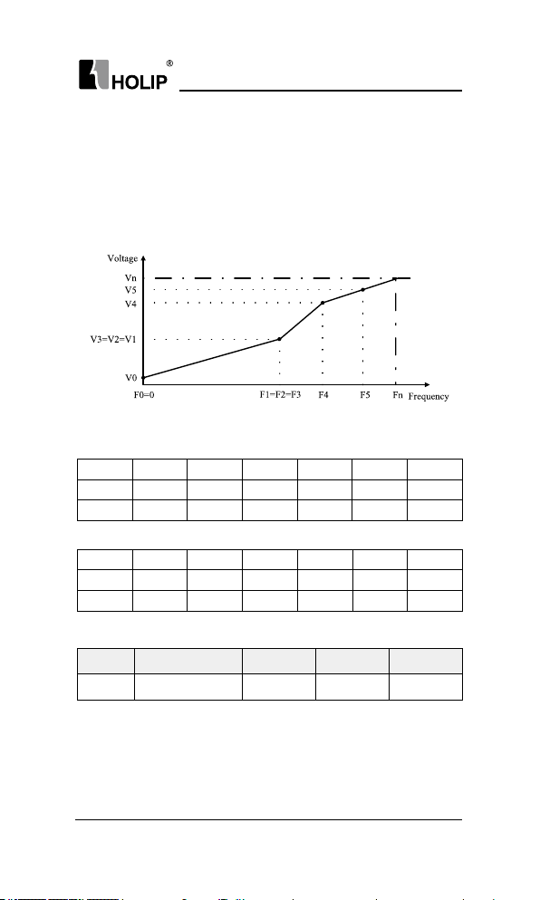
These parameters are array parameters [0-5], used to ma nually form a
V/F characteristic matching the motor. The f requency poi nts[F0-F5] are
dened in C01.56 V/F Charact eristic - F.The voltage at each point[V0-V5]
is defi ned in C01.55 V/F Characteristic - V.These paramet ers are
onlyaccessible when C01.01 Motor Control Principle is set to V/F.
- 46 -
HLP-C100 Ser ies Operating Manual
Page 51
HL P-C10 0 Ser ies
C01.55[0]~C01.55[5] is respective to V0~V5, C01.56[0]~C01.56[5] is
respective to F0~F5,Vn is motor rated voltage,Fn is the motor rated
frequency.
The set of C01.56 must met F0=0 and F1≤F2≤F3≤F4≤F5.
Simplif y V/F characteristicby merging 2 or more points (voltages and
frequencies), which respectively are set equal.
The slope (ratio of V/F) after point (F5, V5) must be equal to the slope
between point (F5, V5) and the previous point.
The defau lt setti ngs of V/F Characteristic are:
200V model:
[0] [1] [2] [3] [4] [5]
C01.55 0.0 7.0 230.0 230.0 230.0 230.0
C01.56 0.0 0.5 50.0 50.0 50.0 50.0
400V model
:
[0] [1] [2] [3] [4] [5]
C01.55 0.0 12 .0 400.0 400.0 400.0 400.0
C01.56 0.0 0.5 50.0 50.0 50.0 50.0
C01.6*Load Depen.Setting
Par. No. Name Range Unit Default
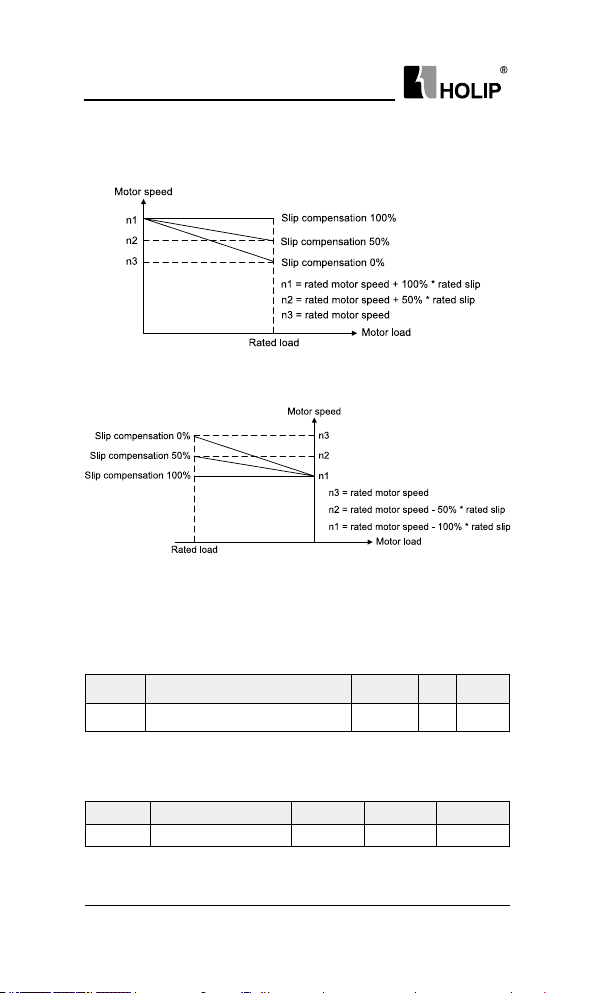
C01.62 Slip Compensation -40 0~39 9 % 100
When the motor is driving an electric-driven load, motor speed d ropswith
the increase of load. When the motor is dr iving a power generat ing load,
motor speed will i ncrease with the increase of load. Appropriate slip
compen sation can maintain const ant motor speed when the motor load is
changing.
If this pa rameter is set to 100%, it indicates that the compensation when
HLP-C100 Ser ies Operating Manual
- 47 -
Page 52
HL P-C10 0 Ser ies
the motor bears rated load is the rated motor slip.
Diagram of slip compensat ion is shown below:
Slip compensation on electric driven load
Slip compensation on power generating load
When having more t han one motor on the same shaft the re is a need for
some kind of load share between t he drives controll ing the motors. This
has ty pically been made with two dr ives running i n speed open loop
mode and one with negat ive slip compe nsation.
Par. No. Name Range Unit Default
C01.6 3 Slip Compensation Time Constant 0.05~5.00 s 0.10
Enter the slip compensation reaction speed. A high value results in slow
react ion, and a low value results in quick reaction. If low-frequency
resona nce problems arise, use a longer ti me setting.
Par. No. Name Range Unit Defau lt
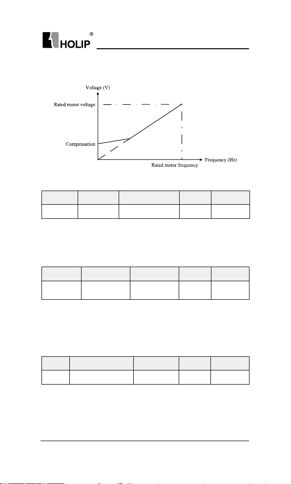
C01.67 Torque Compensation 0 ~200 % 0
Enter the % value to compensate voltage in relation to load when
the motor is runni ng at low speed. 100% corresponds to completely
- 48 -
HLP-C100 Ser ies Operating Manual
Page 53
HL P-C10 0 Ser ies
compen sate for the volt age drop caused by the stator resistance.
Diagr am of torque compensation is shown below:
C01.7*Start Adjustments
Par. No. Name Range Unit Default
C01.71 Start Delay 0.0 ~10.0 s 0.0
This parameter enables a delay of the star ting time. The drive begins
with the star t f unction selected in C01.72. Enter the time delay required
before com mencing accelerat ion.Setting start delay to 0.0 sec. disables
star t functionwhen st art command is g iven.
Par. No. Name Range Unit Default
C01.7 2 Star t Function
Select the start function duri ng star t delay. This parameter is linked to
C01.71 Start Delay.
0: DC Hold, Energizes motor with a DC holdi ng current (C02.00 DC
Hold Cur rent) during the start delay time;
2: Coast, Motor coasted duri ng the sta rt delay time (drive off );
0: DC Hold
2: Coast
2
Par. No. Name Range Unit Default
C01.75 Min. Start Frequency 0.00 ~10.00 Hz 0.00
If the drive f requency reference is less than C01.75 Min. Start Frequency,
the dr ive will not r un even the star t command is given (the st art command
will be shielded). Only the drive frequency reference is greater than or
equal C01.75, then the drive starts to run. The drive still accelerates from
0 to frequency reference using ramp ti me.
HLP-C100 Ser ies Operating Manual
- 49 -
Page 54
HL P-C10 0 Ser ies
Pa r. No. Na me R ange Unit Def ault
C 01.7 6 Jum p Freq uency 0.0 ~20.0 Hz 0.0
If the drive frequency reference’s absolute value (not zero, fre quency
reference maybe negative)is less than C01.76Jump Frequency, the drive
will r un at jump frequency (maybe reversing if the reference is negative).
For examp le:
Set C01.76 = 3. if the freque ncy reference is 2 , the d rive will run forward
at 3Hz; If the frequency reference is -2, the dr ive will r un reversing at
3Hz; If the f requency reference is 0, the dr ive will stop. If the frequency
reference is 20, the drive will r un at 3Hz immediately, then accele rates
from 3Hz to 20Hz using ramp time.
Note: it is not recom mended for using C01.75 and C01.76 toget her.
If C01.75 and C01.76 are used together, the following talbe is its
behaviour.
Freq. ref.
Par. setting
C 01.7 5 = 5.0 0
C 01.7 6 = 10. 0
C 01.7 5 = 10 .0 0
C 01.7 6 = 5. 0
At tent ion: When C01.76 Jump Frequency and C02.04 DC Br ake Cut i n Speed
are not zero, DC brake will only be active when C02.04 > C01.76.
3Hz 8Hz 15H z
Freq. ref<
C 01.75
the sta rt
command
is shielded,
the drive
st op.
Freq. ref<
C 01.75
the sta rt
command
is shielded,
the drive
st op.
Freq. ref >
C 01.75,
the sta rt
command is
given,
Freq. ref <
C 01.7 6
the drive
runs at
10. 0H z
Freq. ref<
C 01.75
the sta rt
command is
shield ed, t he
drive stop.
Freq. ref > C01.75,
the sta rt comma nd is
given,
Freq. ref > C01.76
the drive r uns a t 10Hz
imm edi at ely, the n
accelerates f rom 10Hz
to 15Hz using ramp
ti me.
Freq. ref > C01.75,
the sta rt comma nd is
given,
Freq. ref > C01.76
the dr ive runs at 5Hz
imm edi at ely, the n
accelerates from 5Hz
to 15Hz using ramp
ti me.
- 50 -
HLP-C100 Ser ies Operating Manual
Page 55

HL P-C10 0 Ser ies
C01.8*Stop Adjustments
Par. No. Name Range Unit Default
C01.8 0 Funct ion at Stop
Select the drive function after stop command is given or start com mand
is removed (standby), and output frequency is ramped down to C01.82
Min Speed for Funct ion at Stop.
0: Coast, Leaves motor i n free mode. the drive is off;
1: DC Hold, the motor is energi zed with a DC current. See C02.0 0 DC
Hold Cur rent for more i nformation;
Diagra m of Fu nction at Stop is shown below:
0: Coast
1: DC Hold
0
Par. No. Name Range Unit Default
C01.8 2 Min Speed for Function at Stop 0.0~40 0.0 Hz 0.0
Set the out put frequency at which to activate C01.80 Function at Stop.
6.3 Group 02: Brakes
C02.0*DC-Brake
Par. No. Name Range Unit Default
C02.00 DC Hold Current 0 ~150 % 50
HLP-C100 Ser ies Operating Manual
- 51 -
Page 56
HL P-C10 0 Ser ies
Enter a value for holding current as a percentage of the rated motor
current set i n C01.24 Motor Current. 100% DC holding current
corresponds to IM,N. This para meter either holds the motor (holding
torque) or pre-heats the motor. This parameter is act ive if DC Hold has
been selected in eit her C01.72 Start Function or C01.80 Funct ion at Stop.
At tent ion: Avoid 100% current too long a s it may overheat t he motor.
Par. No. Name Range Unit Default
C02.01 DC Brake Cur rent 0 ~150 % 50
Enter a value for cur rent as a percent age of the rated motor current IM,N,
see C01.24 Motor Current. 100% DC braking current corresponds to
IM,N.
DC brake curre nt is applied on a stop comm and, when the speed is lower
than the limit set in C02.04 DC Brake Cut I n Speed; or v ia the ser ial
commu nication p ort. The braking current is active during the time period
set in C02.02 DC Braking Time.
Par. No. Name Range Unit Default
C02.02 DC Braking Time 0.0 ~60.0 s 10 .0
This parameter defines DC brake current (C02.01) time during which
DC-brake current is applied to the motor.
Par. No. Na me Range Unit Default
C02.04 DC Bra ke Cut in Speed 0.0~400.0 % 0.0
Set the DC brake cut-in speed for act ivation of the DC braki ng current set
in C02.01 DC Brake Cur rent, upon a stop command.
C02.1*Brake Ener gy Funct .
Par. No. Name Range Unit Default
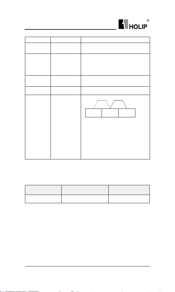
C02.10 Brake Function
0: Off;
1: Resisto r brake, u se the resistor brake to consu me sur plus energy
result ing from motor braking, and prevent the d rive to tr ip due to
over-voltage in the intermediate circuit;
2: AC brake, dissipate su rplus energy in the motor core, and prevent
the energy back into drive causing tr ips. It is important to keep in
mind that frequent use of this function will cause an inc rease i n
motor temperature;
0: Off
1: Resistor brake
2: AC brake
0
- 52 -
HLP-C100 Ser ies Operating Manual
Page 57

HL P-C10 0 Ser ies
Attention: Resistor brake is only f u nctional when the drive build-in braki ng
unit or external braking unit must be installed.
Par. No. Name Range Unit Default
C0 2.11 Brake Resistor 5~65535 Ω *
Set brake resistor value.This parameter is only active i n drives with
an integral brake unit.
Pa r. No. Na me Ra nge Unit Def ault
C 02 .17 Ove r-voltage Con tr ol
Over-voltage control (OVC) reduces the risk of t he dr ive tripping due
toan over volt age on the DC link caused by generative power from the
load.
0: Disabled;
2: Mode 1, used to consume surplus energy by increasing the output
frequency;
3: Mode 2, used for very shor t deceleration;
At tent ion: If C02.10 = 1 (Resistor bra ke), C02.17 = 2 or 3, resistor br ake f unc tion
star ts rst, if the DC link voltage still can not be cont rolled, OVC sta rts.
0: Di sable d
2: M od e 1
3: Mod e 2
0
6.4 Group 03: Reference/Ramps
C03.0*Reference Limits
Re fe re n ce i s the d r ive co nt rol t ar get . Re fe re n ce v al ue i s a
dimensionless numbe r, refer ence u nit de pend s on con figurat ion mode
(C01.00). When select [0] speed open loop in congu ration mode, motor
freque ncy i s the d rive cont rol t arget, t he reference unit is H z; W hen
select [3] process closed loop in conguration mode, process variable (such
as temperat ure, pressu re) is the drive cont rol tar get, the reference unit
may be °C or kg, etc.
Par. No. Na me Range Unit Default
C03.03 Maximum Reference 0.000~4999.000 50.000
Enter value for Maximum Reference. The Maximum Reference is the
highest value obtainable by summing all references.
Par. No. Name Range Unit Default
C03.07
Main Reference
Calculation
0: Preset reference +
Reference source1, 2, 3
1: Preset reference priority
0
HLP-C100 Ser ies Operating Manual
- 53 -
Page 58

HL P-C10 0 Ser ies
Select main reference calculation method.
0: Preset reference + reference sou rce1, 2
1: Preset reference priority
For option [1],
Preset reference[1-N] when use preset reference 1-N
Main refe rence =
Preset reference [0] + Refere nce source1, 2when use preset
reference 0
C03.1*References
Diagr am of Reference Calculat ion is shown below:
- 54 -
HLP-C100 Ser ies Operating Manual
Page 59

HL P-C10 0 Ser ies
Par. No. Name Range Unit Default
C03.10 Preset Reference -100.00~100.00 % 0.00
Th is para me ter is an a rr ay-16 t o be used for pr esett in g di ffe rent
references.16 preset references are sele ctable via digital terminals or local
bus. See C05.1*.0% equals 0, 100% equals value set in C03.03.
Par. No. Name Range Unit Default
C0 3.11 Jog Speed 0.0~4 00.0 Hz 0.0
The jog spe ed is a xed output speed at which the drive is run ning
when the jog f unction is activated.
The dr ive with the highest priority will operate at jog spe ed when a
variety of run command activates. Removi ng the jog sig nal ma kes the
drive ru n accordi ng to th e selec tedconf igu ration, thisp aramete r is set
limit ed by C04.14.
Par. No. Na me Ra nge Unit Defau lt
C03.12 Catch up/Slow dow n Value 0.00~100.00 % 0.00
This parameter e nables the entry of a perce nta ge val ue (relative)
which will to be eithe r added to or deducted from the total refere nce.
The Cat ch up /Slow dow n fu nc tio n is acti vat ed by a d igita l input
ter minal (See C05.1*,choo se [28]/[29]). If this function is active, the
catch up/slow dow n value will be added to the total reference constituting
new setting at which the drive is going to run, calcu lated as follows:
Refere nce= total reference ± t otal referenc e × (Catch up/Slowdown
value)
If this function is inactive, the reference ret urns to its original value.
Par. No. Name Range Unit Default
C03.13 Speed Up/Down Value 0.01~50.00 Hz 0.10
Enter the Speed Up/Down value.
Par. No. Name Ra nge Unit Default
C03.15 Reference Source1
C03.16 Reference Source2 0
Select t he reference input to be used for t he rst, second and thi rd
reference source.
0: No function;
0: No function
1: Ter minal V I
11: Local bus
21: LCP
potentiometer
1
HLP-C100 Ser ies Operating Manual
- 55 -
Page 60

HL P-C10 0 Ser ies
1: Ter minal V I, useanalog input V I as reference source, see C06.1*;
11: Local bus, use local bus reference as refe rence sou rce, see C08.**;
21: LC P potentiometer, use LCP potentiomet er as reference s ource,
see C 06.8*;
Par. No. Name Range Unit Default
Relative
C03.18
Reference
Source
Relative Re ference is si m il ar t o Pr es et R el at ive R efer en ce (s ee
C03.14). It add s a variable value to total reference. Its calculation refers to
Reference Calculation Diagram.
0: No function;
1: Terminal VI, use analog input VI as relative reference source, see
C0 6.1*;
11: L ocal bu s, use local bus reference as relative reference source, see
C0 8.**;
21: LCP potent iometer, u se LCP potentiometer as relative referen ce
source, see C06.8*;
Par. No. Name Range Un it Default
C03.19
the Spee d Up/Down function if the dr ive stops or after it power down.
C03.4*Ramp1
C03.5*, C03.6* and C03.7*), congure the ramp parameters: ramp type,
ramp up t ime and ramp down ti me.
Par. No. Name Range Un it Default
C03.41 Ra mp 1 Ramp Up Time 0.05~300.00 s *
C03.42 Ra mp 1 Ramp Dow n Time 0.05~300.00 s *
C03.51 Ramp 2 Ramp Up Ti me 0.05~300.00 s *
C03.52 Ramp 2 Ramp Dow n Time 0.05~300.0 0 s *
C03.61 Ramp 3 Ramp Up Time 0.05~300.00 s *
C03.62 Ra mp 3 Ramp Dow n Time 0.05~300.00 s *
Speed Up/ Down
Value Store
This parameter is used for setting whether to save the data changed in
There a re 4 ramps built in the drive. For each of four ramps (C03.4*,
0: No function
1: Ter minal V I
11: Local bus
21: LCP
potentiometer
0: No function
1: Stop save
2: Power down save
0
0
- 56 -
HLP-C100 Ser ies Operating Manual
Page 61

HL P-C10 0 Ser ies
C03.71 R amp 4 Ramp Up Time 0.05~300.00 s *
C03.72 R amp 4 Ramp Down Time 0.05~300.00 s *
Ramp UpTime is the time motor accelerates from 0Hz to rated motor
frequency (C01.25).
Ram p Down Time is t he ti me motor decelerates f rom rated motor
frequency (C01.25) to 0Hz.
Ramp Up Time and Ramp Down Time are shown below:
C03.8*Other Ramps
Par. No. Name Range Un it Default
C03.80 Jog Ra mp Time 0.05~3600.00 s *
En te r th e jog r amp time, i. e. t he a cc ele ra ti on /decele ra ti on t im e
between 0Hz and the rated motor frequency (C01.25).
Jog ra mp time sta rts u pon ac tivation of a jog signal via a selecte d
digital input or serial com municat ion port.
Pa r. No. Na me Range Unit Def ault
C03.85 Ramp 5 Ramp Up Time 0.05~300.00 s *
C03.86 Ra mp 5 Ramp Down Time 0.0 5~30 0.00 s *
C03.88 Ramp 6 Ra mp Up Time 0.05 ~300.00 s *
C03.89 Ramp 6 Ram p Down Time 0.05~300.00 s *
C 0 3.91 Ramp 7 Ra mp Up Time 0.05~30 0.00 s *
C03.92 Ra mp 7 Ram p Down Time 0.05~30 0.00 s *
C03.94 Ra mp 8 Ramp Up Time 0.05~30 0.00 s *
C03.95 Ramp 8 Ramp Dow n Time 0.05~300.00 s *
HLP-C100 Ser ies Operating Manual
- 57 -
Page 62

HL P-C10 0 Ser ies
Par. No. Name Range Unit Default
C03.96
are cor responding to ra mp time 1-8. For exa mple, choose preset reference
2 by using terminals cont rol, the ramp time is 3.
Link preset reference and
ramp time
If choose [1] link pre set reference and ramp ti me, preset reference 0-7
0: No link
1: Link
6.4 Group 04: Limits/Warnings
C04.1*Motor Limits
Par. No. Name Range Unit Default
*C0 4.10
prevent unwante d reversi ng.
Par. No. Name Range Unit Default
*C0 4.12
can be set to correspond to the minimum output frequency of the motor
shaft.The Motor Speed Low
Par. No. Name Range Unit Default
*C04.14 Motor Spe ed High Limit C0 4.12~C 04.19 Hz 65.0
can b e set t o cor res pond t o the m aximum manu fac tu re’s rat ed motor
Motor Speed
Direction
Select the motor speed dire ction(s) required. Use this paramet er to
0: Clo ckwis e, the mot or shaf t rot ate s in clock wi se di rection, thi s
setting p revents the motor f ro m ru nn in g in c ou nte r clo ck wise
direction;
1: Co un te r cl oc kwi se , motor s haf t ro ta te s i n coun te r clockw is e
direction, th is setting prevents the motor f rom ru nning in clockwise
direction;
2: Bot h di rec ti on s,wi th t h is s et t in g, t he m ot or ca n ru n i n bo th
directions;
Motor Speed Low
Limit
Set the m inimum limit for Motor Speed, the motor speed low limit
Limit must not exceed the setti ngin C04.14 Motor Speed High Li mit
Set the ma ximum l imit for Motor Speed, the motor speed high limit
0: Clockwise
1: Counter
clockwise
2: Both directions
0.0 ~C04.14 Hz 0.0
2
- 58 -
HLP-C100 Ser ies Operating Manual
Page 63

HL P-C10 0 Ser ies
spe ed.The motor spee d high lim it must exceed the Motor Sp eed L ow
Limit in C04.12.
Par. No. Name Ra nge Unit Default
C0 4.18 Current Limit 0~300 % 150
This parameter is used to set drive output cur rent limit, 100% equals
moto r cur rent set in C01.24. If the output curre nt exce eds the C04.18
motor curre nt lim it, the drive will repor t A.59 warning and current limit
controllers (see C14.3*) start.
Par. No. Name Range Unit Default
*C0 4.19 Max Output Frequency 0.0 ~400.0 Hz 65
Prov ides a f inal limit on the output f requency for i mproved safety
in applications where you want to avoid accidental over-speeding. This
limit isnal in all congurations (independent of the setting in C01.00
Cong uration Mode).
Par. No. Name Range Unit Default
Counting Value of
C04.40
Counter A
Counting Value of
C04.41
Counter B
These parameters are used to set Cou nter A/ B counting value. W hen
Counter A/B reaches the set value, if the par ameter C05.40 relay output
function sets to [38]/[39] Counter A/B reach, the relay acts.
C04.5*Adjustable Warnings
Par. No. Name Range Unit Default
C04.52 War ning Frequency Low 0.0~400.0 Hz 0.0
C04.53 Warning FrequencyHigh 0.1~400.0 Hz 65.0
Enter t he ow /fhigh value. When the motor f requency falls below
ow or exceeds fhig h, a sig nal can be produced on relay. See [15] Out of
frequency range, [16] Below frequency low and [17] Above fre quenc y
high in C05.40.
Diagr am of Warning FrequencyLow and Warning FrequencyHigh are
shown below:
0~0x7FFFFFFFUL 0
0~0x7FFFFFFFUL 0
HLP-C100 Ser ies Operating Manual
- 59 -
Page 64
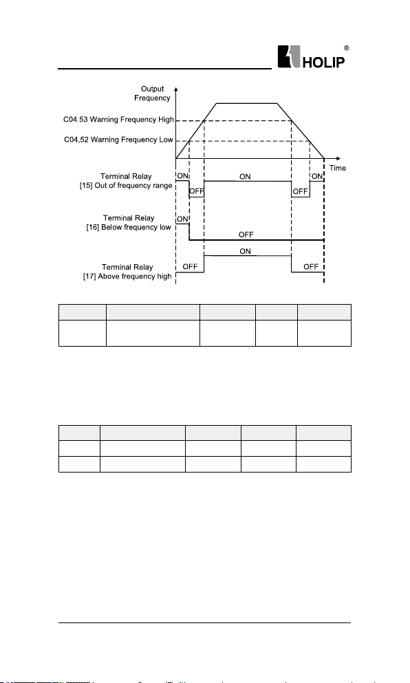
HL P-C10 0 Ser ies
Par. No. Name Range Unit Default
*C04. 58
or 32). Select d isabled for no missing motor phase a larm. It isst rongly
recom mended to make an act ive setti ng to avoid motord amage.
C04.6*Speed Bypass
Par. No. Name Range Unit Default
C0 4.61 By pass Spe ed From 0.0~400.0 Hz 0.0
C04.63 Bypass Speed to 0.0~ 400.0 Hz 0.0
resona nce problem s in the system. A maximum of th ree frequency ra nges
can be avoided.The dr ive will pass quickly when it a pproaching to t he
Bypass Speed area.
range 1, [1] is used to set the bypass speed range 2, and [2] is used to set
the bypass speed range 3.
Missing Motor Phase
Function
Displays a n alarm in the event of a missing motor phase (alar m 30,31
Some s ystems ca ll for avoiding cer tain out put f requencies, due to
These parametersare dya dic array, [0] is used to set the bypass speed
Diagr am of bypass speed ra nges are shown below:
0: Disable
1: Enable
1
- 60 -
HLP-C100 Ser ies Operating Manual
Page 65

HL P-C10 0 Ser ies
6.6 Group 05: Digital In/Out
C05.1*Digital Input
Par. No. Name Range Unit Default
C05.0 4 DI Filter Time 2~16 ms 4
It is used to set the software lter time of DI terminal stat us. If DI
terminals a re liable to i nterference and may cause malfunct ion, increase
the value of this parameter to en hance the anti-interference capability.
How eve r, i nc re as e of DI f il te r ti me w il l re du ce t he r es po nse of DI
terminals.
Par. No. Name Range Unit Default
0: Off
Function at
C05.09
Exter nal Ala rm
The function activates when the digital input terminal function [43]
exter nal alarm input is active.
0: Off, resume s control via serial bus using the most rece nt control
word;
2: Stop and warning, drive stops and reports “A.102”;
3: Joggingand warning, overruled to jog speed and report s “A.102”;
4: Max. speed, overr uled to max.spee d and reports “A.102”;
5: Stop and tr ip, overr uled to stop with subsequent t rip (“E.102”).
Par. No. Name Range Unit Default
C05.10 Terminal FOR
C0 5.11 Terminal R EV 10
C05.12 Te r min al D I1 15
C05.13 Te r min al D I2 16
C0 5.14 Term in al DI 3 17
2: Stop and warning
3: Jogging and warni ng
4: Max. speedand warning
5: Stop and tr ip
0~ 65
0
8
HLP-C100 Ser ies Operating Manual
- 61 -
Page 66

HL P-C10 0 Ser ies
The digital inputs are used for selecti ng various funct ions inthe drive.
All digital inputs can be set to thefollowing functions:
0: No operation, no rea ction to sig nals transmit ted to the termi nal;
1: Reset, reset the drive after a Trip/Alarm;
2: Coa st inver se, no ou tp ut , le av in g th e motor c oasti ng to st op.
Terminal logic ‘0’ => coasting stop;
6: Stop inverse, t he drive is stopped a ccording to selecte d ramp ti me.
Terminal logic ‘0’ => stop;
8: Star t, select start for a star t/stop command. Ter min al logic ‘1’ =
star t, logic ‘0’ = stop;
9: Latched star t, The motor starts, if a pulse is applied for min. 4ms.
The motor stops when [6]Stop inverse/[46]Stop is activated;
10: Reve rsi ng, chan ge di rec tion of moto r shaf t rotat ion, r eversing
signal only changes direct ion of rotation, it does not a ctivate st art
function, C04.10 must choose [2] Both di rection s;
11: Start reversing, used for st art/stop and for reversing at the same
time;
14: Jog, used for activating jog sp eed, see C03.11;
15: Pr es et re f. bit0 , Pre se t ref .b it 0, bit1, bit 2, bi t3 en ab les a
choicebetwee n one of the sixteen p reset refe renc es (see C 03.10)
accord ing to the t able below;
16: Preset ref. bit1, same a s [15];
17: Preset ref. bit2, same as [15];
Terminal of Preset
ref. bit2
OFF OFF OFF C 03.10[0]
OFF OFF ON C 03.10 [1]
OFF ON OFF C03.10 [2]
OFF ON ON C 03.10[3]
ON OFF OFF C03.10[4]
ON OFF ON C0 3.10[5 ]
ON ON OFF C03.10[6]
ON ON ON C03.10[7]
21: Speed up, when Speed up is activated for less tha n 400 ms. t he
resu lting refere nce wi ll be increased by C03.13 Spe ed Up/Down
Value. If Speed up is activated for more than 40 0 ms, the resulting
reference will ra mp accord ing to ramp 4;
22: Speed dow n, similar to [21] Speed up;
28: Catch up, select catch up to increase the resulti ng reference value
by the percentage set in C03.12Catch up/slow Down Value;
- 62 -
Terminal of Preset
ref. bit1
HLP-C100 Ser ies Operating Manual
Preset ref. bit0 Parameter
Page 67

HL P-C10 0 Ser ies
29: Slow down, similar to [28]Catch up;
34: Ramp bit0, ramp bit0, bit1, bit2 are used for select one of the eight
ramps;
35: Ramp bit1, same as [34];
35: Ramp bit2, same as [34];
Terminal of
Ramp bit1
OFF OF F OFF Ramp1 (C03.41, C03.42)
OFF OF F ON Ramp2 (C03.51, C03.52)
OFF ON OFF Ramp3 (C03.61, C03.62)
OFF ON ON Ramp4 (C03.71, C03.72)
ON OFF OFF Ramp5 (C03.85, C03.86)
ON OFF ON Ramp6 (C03.88, C03.89)
ON ON OFF Ramp7 (C03.91, C03.92)
ON ON ON Ramp7 (C03.94, C03.95)
37: Lat ched Reversing, motor sta rts counter-clo ckw iseif a pu lse is
applied for min. 4ms.The motor stop s when [6]Stop inverse /[46]
Stop is activated;
38: JogReversing, similar to [14] jog, but reversing.
42: Coast , similar to [2] coa st reverse, but logic contr ary: Ter min al
logic ‘1’ => coasting stop;
43: External ala rm input, When ter minal is in ON state, the drive w ill
run a s C05.09 speci ed.
46: Stop, similar to[6] stop reverse, but logic contrary: Terminal logic
‘1’ => stop;
60: Count er A, to cou nt the pulse number inputted i nto the terminal;
62: Reset counter A, to clear counte r A to “0”;
63: Counter B, to count the pulse number inputted into t he term inal;
65: Reset counter B, to clear counter B to “0”;
Terminal of
Ramp bit1
Terminal of
Ramp bit0
Parameters
C05 .4*R ela y
Par. No. Name Range Unit Defau lt
C05.4 0 Relay Function 0~55 5
0: No operation;
5: Drive ru nning, the dr ive is run ning;
8: Run on r efere nce/ No warni ng, the drive runs at refe rence speed
without warnings;
9: Alar m, the dr ive alar ms;
HLP-C100 Ser ies Operating Manual
- 63 -
Page 68
HL P-C10 0 Ser ies
10: Alarm or warni ng, an alarm or war ning occurs;
15: Out of frequency range, output frequency is outside the range set
in C04.52 and C04.53;
16: Below frequency low, output frequency is lower t han set in C04.52;
17: A bove f requ enc y hig h, output freque ncy is hig her tha n set in
C04.53;
21: Thermal wa rning, a thermal warning occurs;
24: Read y, volt age OK, the driv e is ready for oper ati on, no over-
voltage or under-voltage is present;
25: Reverse signal, the drive has reve rse signal;
26: Bus OK, local bus communication is normal;
38: Counter A reach, cou nter A reaches the C04.40 setti ng value;
39: Counter B reach, cou nter B rea ches the C04.41 setting value;
43: External alar m, the d igital input termi nal function [43] external
alar m inputis active;
51: Drive in HANDstat e;
52: Drive in AUTOstate;
53: No alarm;
55: Reverse, the d rive ru ns in counter clockwise;
6.7 Group 06: Analog In/Out
C06.1*Analoge Input VI
Parameters for congur ing the scaling and limits for analogi nput VI.
Par.
No.
C06.10 Ter minal V I Low Voltage 0 .0 0 ~C0 6.11 V 0.07
C0 6.11 Terminal V IHigh Voltage C06.10~10.00 V 10.0 0
C06.12 Terminal V ILow Cu rrent 0.00 ~C06 .13 mA 0 .14
C06.13 Terminal V IHigh Current C06.12~2 0.0 0 mA 20.00
Terminal VILow Ref./
C0 6.14
Feedb. Value
Terminal VIHighRef./
C06.15
Feedb. Value
C0 6.10 is u se d to s et lo w vol ta ge i np ut;C0 6.12 is u se d to s et low
cur rent input; The low voltage and cur rent analog input s cali ng value
corresponds to the lowref./feedb. value, set in C06.14.
C06.11is us ed to s et high voltage in put;C06.12is u sed to set hig h
cur rent input; The h igh voltage and current a nalog input scaling value
corresponds to the high ref./feedb. value, set in C06.15.
- 64 -
Name Range Unit Defau lt
-4999.000~4999.000 0.000
-4999.000~4999.000 50.000
HLP-C100 Ser ies Operating Manual
Page 69
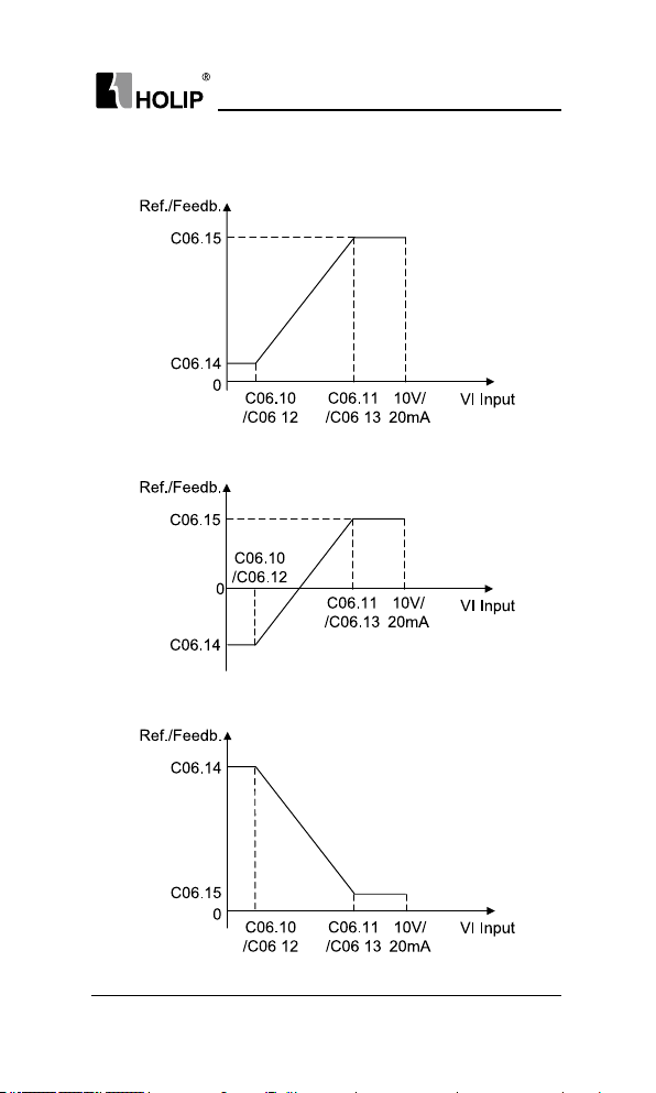
HL P-C10 0 Ser ies
There are 4 kind of curves between ter minal VI i nput voltage/curre nt
and its scale value:
C06.14 < C06.15 and C06.14 >= 0
C06.14 < C06.15 and C06.14 < 0
C06.14 > C06.15 and C06.15 >= 0
HLP-C100 Ser ies Operating Manual
- 65 -
Page 70

HL P-C10 0 Ser ies
C06.14 > C06.15 and C06.15 < 0
Terminal VI reference/feedba ck value calculated as follows:
If C06.10 <= VI Input<= C06.11,
VI Ref./Feedb.Value = (C06.15 - C06.14) ÷ (C06.11 - C06.10) × (VI input
- C06.10) + C06.14;
If VI Input< C06.10,
VI Ref./ Feedb.Value = C06.14;
If VII nput> C06.11,
VI Ref./ Feedb.Value = C06.15;
Note: Above formulasare for voltage input.If it is a cur rent input, C06.10
and C06.11 use C06.12 and C06.13 instead respectively.
Par. No. Name Range Unit Default
C0 6.16 Terminal VI Filter Ti me 0.01~10.00 s 0.01
Enter the terminal VI lter time. This is a rst-order d igital low pass
lter for suppressing electrical noise in terminal VI.A high time constant
value improves dampening but also increases the time delay through t he
lt er.
Par. No. Name Range Unit Default
Terminal VI Zero Dead
C0 6.18
Band
Set the dead-band of V I at 0 speed. When analog input VI ref. low and
ref. high h ave opposite sig ns, there must be a set point that corresponding
to an a nalog ue value equals 0. In o rder to prevent the set point jitter
at zero point due to anal og int erfe rence, th is parame ter should b e set
properly.
- 66 -
HLP-C100 Ser ies Operating Manual
0.0~20.00 V/m A 0.00
Page 71
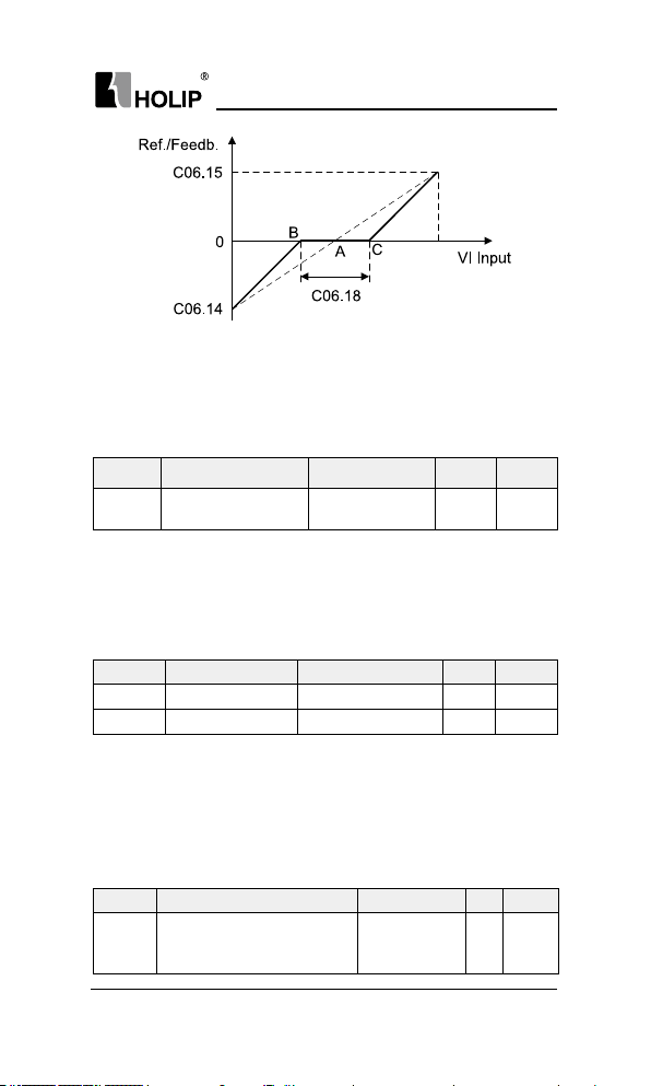
HL P-C10 0 Ser ies
Point A as show n in the f igure is the analog value that corresponds to
a setpoint that equals 0. It is calculated via analog low, high values and
low, high reference/feedback values. After setter minal VI zero dead
band, UAB=UAC=C06.18/2. If the VI input is between B and C, the VI
reference/feedback is 0.
Par. No. Name Range Unit Default
C06.19 Terminal VI Mode
Select the inputto be present on analog input VI.
C06.8*LCP Potentiometer
The LCPPotentiomet erca n be select either as refe rence resou rce or
relative reference source.
Par. No. Name Range Un it Default
C06.81 LCP Pot.Mi n. Ref. -4999.000~4999.000 0.000
C06.82 LCP Pot.Max. Ref. -4999.000~4999.000 50.000
These paramet ers are u sed to set the mini mum/m aximu m reference
ofLCPPotentiometer. The reference of LCP potentiometer's per division
depends on the set of the C00.47 LCP potentiomete r step.
0: Voltage mode
1: Curre nt mode
0
6.8 Group 07: Controllers
C07.2*Process PI D Feedback
Par. No. Na me Range Unit Default
C07.20 Process PID Feedback Source
HLP-C100 Ser ies Operating Manual
0: No function
1: Ter minal V I
11: Local bus
- 67 -
0
Page 72
HL P-C10 0 Ser ies
Select sou rce of feedback signal.
C07.3*Process PID Control
This par amet er is active i n close d loop process cont rol mo de (See
C01.00Cong uration Mode).
Par. No. Name Range Unit Default
C0 7.31 Process PID Anti Windup
Th is func tio n ens ur es th e out put f re que ncy r eac hes t o fr equ enc y
limit. PID-cont roller will be i nitialized to the current fre quency when
the output frequency can not b e changed. This can prevent the integrat or
continue to integ rate on an er ror when the PID -controller can’t adjust
output frequency.
0: Disable, continue regulation of a given er ror even whe n the output
frequency can’t be increased/decreased;
1: Enable, ceases regulation of a given er ror when the output frequency
can’t be increased/decreased;
Par. No. Name Range Unit Default
C0 7.3 3 Process PID Proportional Gain 0.00 ~10.00 0.01
Enter the PID propor tional gain. The proport ional gain multiplies the
errorbetween the set point and the feedback signal.
Attention: This funct ion is disabled when it is set to “0”.
Par. No. Name Range Unit Default
C0 7.3 4 Process PID I ntegral Time 0.10~9999.00 s 9999.00
Ente r the PID integral t ime. T he int egrator pr ovide s an increasing
gainat a con stant error between the set poi nt and t he feed back signal.
Theintegral t ime is the t ime needed by the integrator to reach the same
gaina s the proportional gain.
Par. No. Name Range Unit Default
C0 7.3 8 Process PID Feed Forward Factor 0~400 % 0
En te r t he PID f ee d fo r wa rd ( F F) f ac tor. T he FF f ac tor sen ds a
constant fraction of the refe rence signal to bypa ss the PID control, so the
PID control only affects the remaining fraction of the cont rol signal. Any
change to this par ameter w ill thus affect the motor speed. When the FF
factor is activated it provides less overshoot, and h igh dynamics when
changing the set point.
0: Disable
1: Enable
0
- 68 -
HLP-C100 Ser ies Operating Manual
Page 73

HL P-C10 0 Ser ies
Par. No. Name Range Unit Default
C0 7.3 9 On Reference Bandwidt h 0.0~200.0 % 0.1
Enter the On Reference Bandwidt h. When t he PID Control Error (the
difference b etween the reference and the feedback) is less t han the set
value of this parameter, the PID control stops.
Par. No. Name Range Unit Default
C0 7.41 Process PID Output Low -100 ~100 % 0
C0 7.4 2 Process PID Out put High -10 0~10 0 % 100
These parameters are used to set process PID controller output low/
high li mit, 100% cor responds to C04.19.
6.9 Group 08: Communication
C08.0*Comm. General Settings
Par. No. Name Range Unit Default
C08.02
not.
C08.03 Control Word Timeout Time 0.1~6500.0 s 1.0
of two consecut ivetelegram s. If this time i s exceeded, it indicates that
the serial com municationhas stopped. The function sele cted in C08.04
Cont rol Word Timeout Func tion wi llthe n be car ried out. The t ime- out
counter is triggered by a valid control word .
the control word fails to be updated within the time period specied in
C08.03 Cont rol Word Timeout Time.
Control Word
Selection
This parameter is used to select whether the cont rol word is active or
Par. No. Name Range Unit Default
Ent er the maxim um time e xpe cte d to pass between t he re ceptio n
Pa r. No. Name Range Unit Def ault
C08.04
Control Word
Timeout Function
Select the time-out function. The time -out f unct ion activates when
0: Disable
1: Enable
0: Of f
2: St op
3: Jog g in g
4: M a x. sp eed
5: Stop and tr ip
1
0
HLP-C100 Ser ies Operating Manual
- 69 -
Page 74

HL P-C10 0 Ser ies
0: Off, resume s control via serial bus using the most rece nt control
word;
2: Stop, overruled to stop;
3: Jogging, over rule d to jog speed;
4: Max. speed, overr uled to max.spee d;
5: Stop and tr ip, overr uled to stop with subsequent t rip (“E.17”).
Par. No. Name Range Unit Default
C08.06
Afte r control word t imeout occurs, a control word inter rupt ag will be
within the drive. It must be use the parameter to clear the ag (Do reset),
else even to restore commun ication or clear "E.17" alar m, t he d rive will
continue to report control word timeout.
Par. No. Name Range Unit Default
C08.29
warn ing/ala rm modes:
drive occurs E.13 ala rm, the value of regist er 51101 is 13.
C0 8.3*Por t Se tt in g
C08.31 Address 0 ~247 1
range is 1-247.
Par. No. Name Range Unit Default
C08.32 Baud Rate
Reset Control Word
Timeout
Rese tti ng control wo rd timeout w ill remove any timeout f unction.
0: Do not reset, control word timeout is not reset;
1: Do reset, control word ti meout is reset;
Commu nication Alarm
Mode
Register 51101 is used to store the drive fault information, it ha s two
0: Bit mode
Each register bit represents a different warn ing and failure.
1: Code mode
Warning/alar m code is stored in the register. For example: W hen t he
Par. No. Name Range Unit Default
Select the address for the bu s. FC-bu s range is 1-126, and Mod bus
0: 2400
1: 4800
2: 9600
3: 19200
4: 38400
0: Do not reset
1: Do reset
0: Bit mode
1: Code mode
bit/s
0
0
2
- 70 -
HLP-C100 Ser ies Operating Manual
Page 75
HL P-C10 0 Ser ies
Select baud rate for com munication.
Par. No. Name Range Unit Default
0: Even parity (1 stop bit)
C08.33 Parity/Stop Bits
This parameter only effective for Modbus and FC bus always has even
pa rity.
Par. No. Name Range Unit Default
C08.35 Min. Response Delay 0.001~0.50 0 s 0.002
Specify the mi nimum delay ti me bet ween receiving a request a nd
transmitt ing a response. This is used for overcoming modem turnarou nd
delays.
Par. No. Name Range Unit Default
C08.36 Max. Response Delay 0.010 ~10.00 0 s 5.000
Specify the maximu m permissible delay time between tran smitting
a request and receiv ing a resp onse. If exceeds this delay time, t he drive
will not respond to received data.
Par. No. Name Range Unit Default
Message
C08.38
Response
This parameter is used to control Modbus message response.
Atte ntion: the dr ive will response the READ instruct ion no mat ter
what C08.38 set.
Par. No. Name Range Unit Default
Modbus Parameter
C08.39
Writ e Stor e
Thi s para mete r is used to cont rol whether the paramete rs which is
changed by Modbus WR ITE in struction are saved or not at power down.
1: Odd parit y (1 stop bit)
2: No parit y (1 stop bit)
3: No parity (2 stop bit)
0: Normal
1: Only response except ion
message
2: Not respon se
0: Not saved at power
down
1: Saved at power down
2
0
0
HLP-C100 Ser ies Operating Manual
- 71 -
Page 76

HL P-C10 0 Ser ies
6.10 Group 14: Special Funct ions
Par. No. Name Range Unit Default
2~6: 2~6kHz
C14.01 Switching Frequency
Switching frequency has asignicant inuence to the drive and the
motor. Select appropriate swit ch frequency c an help to a djust acoustic
noise from the motor、power consumption and the d rive efciency. When
swi tching f req uency inc rea ses , the c onsumption a nd th e nois e of the
motor are reduced , but the dr ive’s temperat ure will increa se, and motor
lea kage a nd th e interferen ce to t he ext ernal de vice will incr eas e; the
contrary, the opp osite.
Par. No. Name Range Unit Default
*C14.03 Overmodulation
The overmodulation f unction c an obt ain a n output voltage gr eate r
than mains voltage.
0: Off, disable the overmodulation function to avoid torque ripple on
the motor shaft. This feature may be useful for applications such as
grinding machines.;
1: On, con ne cts t he over modul at ion fun ct ion to obt ain an out put
voltage up to 5% greater than mains voltage. Overmodulation leads
to increased torque ripple as harmonics are increased;
Pa r. No. Na me R ange Unit Def au lt
C14. 08 Damping Gain Factor 0 ~200 % 96
Damping gain factor can help to i mprove the re sponse speed of the
DC lin k of the drive making the DC loop sig nal more smooth.
7: 8kHz
8: 10kHz
9: 12kHz
10: 16kHz
0: Off
1: On
kHz *
1
C14.1*Mai ns On/Of f
Par. No. Name Range Unit Default
Function at Mains
C14.1 2
Imbanlance
Select actions when a m ains i mbala nce is detect ed. Th e dection of
mains imbalance depend s on load. In order to meet different applicat ions,
- 72 -
HLP-C100 Ser ies Operating Manual
0: Trip
1: Warning
2: Disabled
0
Page 77

HL P-C10 0 Ser ies
different sensit ivity options are set for this pa ramete r.
0: Trip, the drive trips (reports " E.04") when a mains imbala nce is
detected;
1: Warni ng, the dr ive issues a warning (reports "A.04") but continues
to ru n when a mains imbalance is detected;
2: Dis ab le d, the dr ive do es not hing wh en a m ain s im bal an ce is
detected. Be attention to u se this option;
The dect ion method for option [4] a nd [5] is middle sensitive.The
drive trips (option [5]) or issues a warning (option [4]) at low frequency
and heav y loaded, or high frequency and low load.
The dection method for option [6] is high sensitive.Mains imbalance
can be detected immediately. But there is minimu m risk of false positives
(generally occu rs in an abnormal g rid or the d rive over-cu rrent protection
frequently).
Par. No. Name Range Unit Default
Automatic Voltage
C14.17
Regulation
When motor voltage 12%~20% higher than rated, motor temperature
wi ll i nc re as e, i ns ul at ion cap ab il it y de st royed , the to rq ue out put is
unst able, long-term operation will cause the motor short en its life.
Automatic volta ge reg ulat ion ca n automatically cont rol the out put
voltage at the motor's rated voltag e when t he gr id volt age exceed t he
rated motor voltage.
Turn off automatic voltage regulat ion will improve the ability of rapid
deceler ation, but t urn off this opt ion need to be cautious, it will cause the
output volt age diffe rent due to d ifferent grid voltage, there is a n increased
risk of heat damage to the motor.
This feature can only be turned off when in VF mode.
Par. No. Na me Range Unit Default
C14.18
This parameter is used t o dene the drive action when power up again
after power loss during runni ng.
If it is set to 3600.0, the dr ive does not respond to the start command
val id upon dr ive power- on (for example, start term in al is ON b efor e
power-on). The d rive responds only after the start command is cancelled
and becomes valid again.
If it is set to 0.0~3599.9, the d rive will respond to the start command
Delay Time of Auto
RestartWhen Power up
Again
0: Disable
1: Enable
0.0~3600.0 s 0.0
1
HLP-C100 Ser ies Operating Manual
- 73 -
Page 78

HL P-C10 0 Ser ies
delaying the C14.18 sett ing time upon drive power-on (for example, start
terminal is ON before power-on).
C14.2* Tri p Re set
Par. No. Na me Range Unit Default
0: Manual reset
C14. 20 Reset Mode
Select reset function after tripping.
0: Manual reset, perform reset via “OFF”butt on or digital inputs;
1~10: Aut o reset 1-10times, can perform 1-10 automatic resets after
trips;
11: Auto reset 15 times, can perform 15 automatic resets after t rips;
12: Auto reset 20 t imes, ca n perfor m 20 automatic resets after t rips;
13: I nn ite auto reset, can perform an i nn ite number of automatic
resets after t rips;
Once option [1] - [13] is selected, the drive will be restart ed after an
alar m. If reset has been done and the runni ng signal is active, the drive
will restar t automatically. For option [1] – [12], if the drive performs a
set number of aut omatic reset, fault still can not be removed, t he drive
will remain a tripstate. It needs power off and on to reset the trip after
shootingfault.
Be atte ntion to select option [13], it may cause i nnite auto reset.
Par. No. Name Range Unit Default
C14. 21 Automatic Rest art Time 0~600 s 10
Ente r time inte rval from t rip t o start of aut omat ic reset fu nction
after an alar m.This parameter is a ctive when C14.20Reset Mode is set to
automat ic reset [1]-[13].
Par. No. Name Range Unit Default
C14. 22 Operation Mode
0: Normal operation;
2: Initialization, i nitial ise all the parameters except information about
the dr ive itself and the recorded parameters.
1~10: Auto reset 1-10 times
11: Auto reset 15 times
12: Auto reset 12 times
13: Innit e auto reset
0: Normal operation
2: Initialization
3: Backup user settings
4: Recover user setti ngs
0
0
- 74 -
HLP-C100 Ser ies Operating Manual
Page 79

HL P-C10 0 Ser ies
3: Backup user settings;
4: Recover user setti ngs;
For option [3] to [4], after modify ing the drive pa rameters based on
the fu nctional requirements, OEM manufacturers can set C14.22 = 3 to
backup settings. If the end users modify parameters and can not be selfrecover y, it can be recovered by sett ing C14.22 = 4 or pressi ng "OFF" key
on LCP 5 seconds (the default ti me, can be modied by C00.46 One Key
Recove ry Time).
Par. No. Name Range Unit Default
C14. 23 Tri p lock
0: Disable, t rip lock fault reset do not need power off;
1: Enable, trip lock fault re set need power off;
C14.3* Current Limit Control
The dr ive contai ns two current limit controllers. T he two cont rollers
will be enabled when the cu rrent is over C04.18 current li mit.C urrent
controller1 controls current by reducing the output f requency, and current
cont roller2 controls cur ren t by reducing the out put voltage. Typical ly
only recommende d to use current controller1, if it is still unable to control
the current in some occasions (such as fast acceleration and deceleration),
you can use the current controller2.
Par. No. Name Range Unit Default
Cur rent Controller 1
C14. 30
Proportional Gain
Cur rent Controller 1Integration
C14.31
Time
C14. 32 Current Controller Filter Time 0 ~100 ms 1
Cur rent Controller 2
C14. 33
Proportional Gain
Cur rent Controller 2Int egration
C14. 34
Time
It ca n adjust the d yn amic re spo nse cha racte ri sti cs of t he cu rren t
controllers by set ting the proportional gai n and integration t ime.
Cho ose a hig her v alu e of proport ional ga in a nd lowerint egrat ion
time causes the controller res ponse more quickly, but too highvalue of
proportional gain and tow low value of i ntegration ti me will cause the
controller unstable.
0: Disable
1: Enable
0
0~50 0 % 100
0.000~2.000 s 0.020
0~300 % 0
0.001~2.000 s 0.020
HLP-C100 Ser ies Operating Manual
- 75 -
Page 80
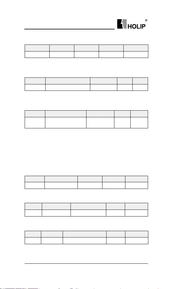
HL P-C10 0 Ser ies
C14.4*Energy Optimising
Par. No. Name Range Unit Default
*C14.40 VT Level 40~90 % 90
Enter the le vel of motor mag netisation at low s peed. Sele ction of
a low v alu e reduc es ener gy loss i n the mot or, but al so re duces l oad
capability.
Par. No. Name Range Unit Default
*C14.41 AEO Mi n. Magnetisation 40 ~75 % 66
Enter the minimum allowable m agnetisation for AEO. Selection of a
low value reduces energy loss in t he motor, but can also reduce resista nce
to sudde n load changes.
Par. No. Name Range Unit Default
*C14 .51
f luc tu at ions in the D C li nk . Low tor que ripple. In s ome cas es , th is
dynamic compensation may cause resonance problems in DC li nk circuit
and then this fu nction should be disabled.
DC Link
Compensation
This f unction ensure s the output voltage is independent of any voltage
0: Off
1: On
0
6.11 Gro up 15: Dr i ve In f orm ation
C15.0*Operating Data
Par. No. Name Range Unit Default
C15.00 Operating Days 0 ~9999 d
Vi ew how ma ny da ys th e d riv e has run . The va lu e i s save d
automat ically at power off and can’t be reset.
Par. No. Name R ange Unit Default
C15.02 kWh Count er 0 ~65535 kWh
View the power consumption of the motor as a mean value over one
hour. Reset the counter in C15.06 Reset kWh Cou nter.
Par. No. Name Range Unit Default
C15.03 Power Up’s 0~2147483647
View th e nu mb er of ti me s th e dr ive has been powe re d up. T his
parameter can’t be reset.
- 76 -
HLP-C100 Ser ies Operating Manual
Page 81
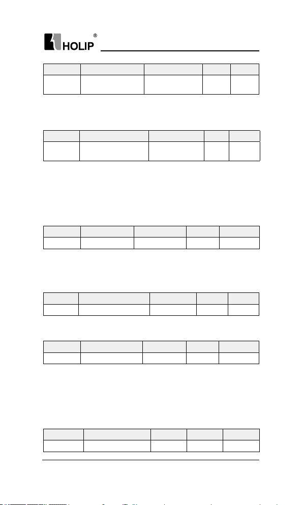
HL P-C10 0 Ser ies
Par. No. Name Range Un it Default
C15.06 Reset kWh Counte r
0: Do not reset;
1: Do reset, kWh counter is reset to zero (see C15.02 kWh Counter);
Attent ion: This pa rameter can’t be set via local bus.
Par. No. Name Ra nge Unit Default
Reset Running Hours
C15.07
Counter
0: Do not reset;
1: Do reset, running hours counter is reset to zero (see C15.01Running
Hou rs);
Attent ion: This pa rameter can’t be set via local bus.
C15. 3*Fau lt Lo g
Par. No. Na me Range Unit Default
C15.30 Ala rm Code 0~255
Vie w the ala rm cod e and look up its mea ni ng in cha pter 8. Thi s
parameter is a n array [10] paramete rs. It contains a alarm log showing
reasons for the ten latest trips. C15.30[0] represents the latest, C15.30[9]
is a recent 10th, this parameter cannot be reset.
Par. No. Name Range Unit Default
C15.31 Internal Fault Reason -32767~32767
Th is pa ra me ter c onta in s i nt er nal fau lt r ea so ns , mo st ly u sed i n
combination with alarm E.38.
Par. No. Name Range Un it Default
C15.38 Warn in g C ode 0~2 55
View the warning code and look up its meaning in ch apter 8. This
parameter is an array [10] par ameter s. It contains a war ning log showing
re asons for the ten late st war ni ngs. C15.38[0] rep re sen ts the latest ,
C15.38[9] is a recent 10th, this parameter cannot be reset.
0: Do not reset
1: Do reset
0: Do not reset
1: Do reset
0
0
C15.4*Dri ve Ident icat ion
Par. No. Name Range Unit Default
C15.43 Software Version
HLP-C100 Ser ies Operating Manual
- 77 -
Page 82

HL P-C10 0 Ser ies
View the software version of the dr ive.
6.12 Group 16: Data Readouts
This parameter group is read-on ly.
C16.0*General Status
Par. No. Name Range Unit Default
C16. 00 Control Word 0 ~65535
View latest valid contr ol word that sent to the drive via loca l bus.
Turn it int o 16-bit bi nar y co de. For the mean ing of each bits , please
refer to register 2809 and coils 0~15 description in appendi x A Modbus
Communication Specication.
Par. No. Name Range Unit Default
C16. 01 Reference -4999.000~ 4999.000
View the actual reference.
Par. No. Name Range Unit Default
C16. 05 Motor Speed 0~9999 rpm
View motor speed.
Par. No. Name Range Unit Default
C16. 09 Custom Readout 0.00~9999.00
View the value of user-dened readout corrected from C00.31, C00.32
and C04.14.
C16 .1* Mo t or St a t us
Par. No. Name Range Unit Default
C16.10 Output Power 0.000~1000.000 kW
View output power in kW.
Par. No. Name Range Unit Default
C16.1 2 Motor Voltage 0 ~65535 V
View motor phase voltage.
Par. No. Name Range Unit Default
C16.13 Output Frequency 0.0~ 400.0 Hz
- 78 -
HLP-C100 Ser ies Operating Manual
Page 83
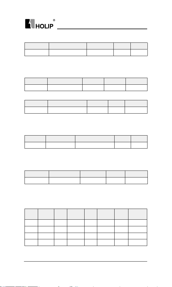
HL P-C10 0 Ser ies
View output frequency.
Par. No. Name Range Unit Default
C16.14 Output Current 0.00~655. 35 A
View motor phase cur rent.
C16. 3*Dr iv e Sta tus
Par. No. Name Range Un it Default
C16. 30 DC Lin k Voltage 0 ~65535 V
View DC-li nk voltage.
Par. No. Name Range Unit Default
C16. 34 IGBT Temperature 0 ~65535
View the temperat ure of dr ive’s IGBT Temperature.
C16.5*Ref./ Feedb.
Par. No. Name Ra nge Un it Default
C16. 52 Feedback -4999.000~4999.000
View the feedback value.
C16.6*, C16.7*I np ut s a nd Out pu ts
Par. No. Name Range Unit Default
C16. 60 Digital Input 0~ 65535
View signal states from active digital inputs, which indicates in a 16-
bit binary code. If the drive detects digital input term inals connected, the
correspondi ng position is set to “1”, otherwise “ 0”. Digital i nput ter minal
and the corresp onding relationship between the binary code are as below:
Ter m.
Binar y
No.
bit0 FOR bit4 DI3 bit8 Reserved bit12 Reserved
bit1 REV bit5 Reserved bit9 Reserved bit13 Reserved
bit2 DI1 bit6 Reserved bi t10 Reserved bi t14 Reserved
bit3 DI2 bit7 Reserved bi t11 Reserved bit15 Reserved
Binar y
Ter m.
No.
Binar y
Ter m.
No.
℃
Binar y Ter m. No.
HLP-C100 Ser ies Operating Manual
- 79 -
Page 84
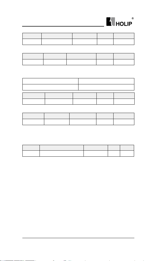
HL P-C10 0 Ser ies
Par. No. Name Range Unit Default
C16. 62 Analog Input VI 0.00~20.00 V/m A
View actual input volt age or cur rent value on analog input VI.
Par. No. Name Range Unit Default
C16.71 Relay Output 0~65535
View the out put statu s of the relay, the corre sponding bit is set to
“1”whenthe relay output is act ive, other wise it will be set to “0”.
Binar y bit0
Item. No. Relay 1
Par. No. Name Range Unit Default
C16.7 2 Counter A 0~2147483647
View prese nt value of counter A.
Par. No. Na me Range Unit Default
C16.7 3 Counter B 0 ~2147483647
View prese nt value of counter B.
C16.8*Field bus/FC Por t
Par. No. Name Range Unit Default
C16. 86 Communication Reference -3276 8~32767
View the last received reference from commu nication.
- 80 -
HLP-C100 Ser ies Operating Manual
Page 85
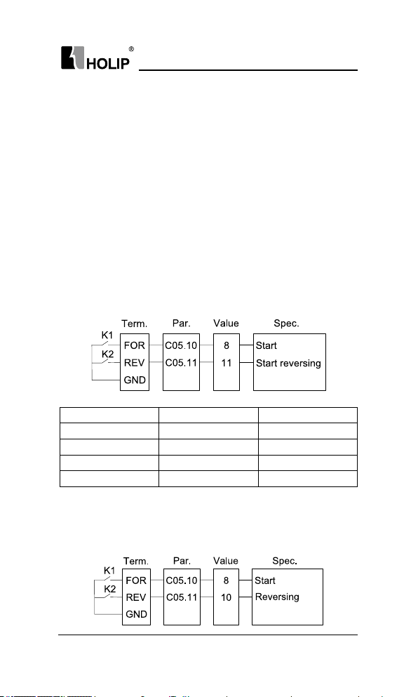
HL P-C10 0 Ser ies
Chapter 7 Quick Application Guide
7.1 Using LCP to Start /Stopthe Drive
1. Press “HA ND” key on LCP to star t the drive;
2. Turn t he potentiometer to change output frequency;
3. Press“OFF”key on LCP to stop the dr ive;
7.2 Using Digital InputTerminals to Start/Stopthe Drive
Usually there are four mode for using digital input terminals to sta rt/
stop the d rive. No mat ter what mode, press “AUTO” key on LCP rst.
7.2.1 Two-l ine Mode 1
It is the most commonly used two-line mode, in which the forward /
reverse rotation of t he motor is de cided by FOR and REV. Wiring a nd
parameters are set as below:
K1 K2 Command
OFF OF F Stop
ON OFF Run forward
OFF ON Stop
ON ON Run reverse
7.2.2 Three -line Mode 1
In t hi s mo de, FOR i s ru n en ab led t er m in al, and the d irec ti on i s
decided by DI1 and DI2. Wir ing and pa ramete rs are set a s below:
HLP-C100 Ser ies Operating Manual
- 81 -
Page 86
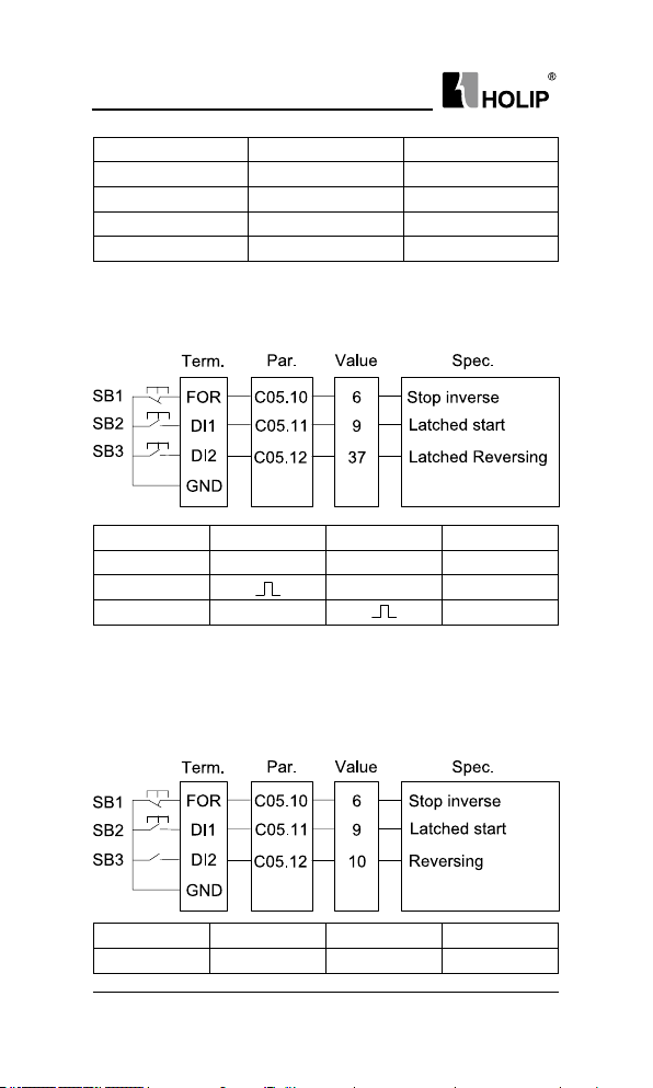
HL P-C10 0 Ser ies
K1 K2 Command
OFF OF F Stop
ON OFF Run forward
OFF ON Stop
ON ON Run reverse
7.2.3 Three -line Mode 1
In t hi s mo de, FOR i s ru n en ab led t er m in al, and the d irec ti on i s
decided by DI1 and DI2. Wir ing and pa ramete rs are set a s below:
SB1 SB2 SB3 Command
OFF × × Stop
ON
ON ×
× Run for ward
Run reve rse
7.2.4 Three-line Mode 2
In this mode, FOR is run e nabled t erm inal. T he RUN command is
given by DI1 and the direction is decided by DI2. Wiring and parameters
are set as below:
SB1 SB2 SB3 Command
OFF × × Stop
- 82 -
HLP-C100 Ser ies Operating Manual
Page 87

HL P-C10 0 Ser ies
ON OFF Run for ward
ON
ON Run reverse
7.3 Multi-speed
In s ce na ri os wh er e th e ru n ni ng f re quenc y of the drive ne ed not
be adjuste d con tinuously a nd only several f reque ncies ar e requi red,
the m ulti-speed cont rol can be used. The d rive supp orts a ma xim um
of 16 ru nn ing f requencie s in ea ch set-up, whic h are i mplemented b y
st ate com bi nat io ns of f ou r DI te rminal s. Set the pa ra me ter numbe r
correspondi ng to DI term inals to a value among 15 to 18 (Preset ref. bit
0~3), and then the DI terminals a re speci ed as the multi-frequency input
te rmi nals. The mul ti ple f requenci es a re s et based on the m ul ti fre qu enc y ta bl e in gr ou p FC . I n ad dit io n, y ou n eed t o se t C03. 03
(Maximum Reference). The followi ng gu re shows how to set the multi-
speed function.
In the preceding gure, FOR , R EV are set as two-li ne mode 1, DI1,
DI2, DI3 and DI4 are used a s the multi-frequency input terminals, each
of wh ich h as a bit va lue . The sta te combinati ons o f these t er mi na ls
correspond to multiple frequencies, When (DI4, DI3, DI2, DI1) = (0, 0,
1, 0), the state combination value is 2, corresponding to t he value set in
C03.10[2]. The target runningfrequency is automatically calculated by
C03.10[2] x C03.03.
The d rive su ppor ts a ma ximu m of four DI t erm inals to be used as
the multi-freque ncy input terminals. You can also use less than four DI
terminals, and the empty bit is considered to be 0.
7.4 Analog Input as the Frequency Source
Th e VI/A I te r mi nal s ca n be use d as the fr eq ue nc y so ur ce. The
following g ure shows how to use the VI as the frequency source.
HLP-C100 Ser ies Operating Manual
- 83 -
Page 88

HL P-C10 0 Ser ies
Attention: Parameters and thei rs value in dash box should be set according
to the application.
7.5 Speed up/down
When you need speed ne t uni ng at a xed value, you ca n use the
speed up/down via terminals. The following gures show how to use the
function:
7.6 Parameter Initialization
1. Set C14.22 = 2;
2. Cut off the main power and Re-power on, LCP d isplays “E.80”;
3. Press “OFF” key on LCP;
- 84 -
HLP-C100 Ser ies Operating Manual
Page 89

HL P-C10 0 Ser ies
Chapter 8 Faults and Solutions
8.1 Fault List
The drive has three different fault types: warning, alarm and error.
When a fault happens, the drive shows a specic code to indicate it.
Wh en a w ar ning happens, it m ea ns t ha t th e dr iv e is cl os e to its
design limits for some reason, but the dr ive still works. If the d rive fault
disa ppea r, the warni ng will also di sappear. When a war ning happe ns,
LCP displays “A.XX” (XX is warn ing code).
An alarm means that the d rive has exceeded its design lim its for some
reason. When th is happens, the drive will t rip. The d river must be reset
in order to re -run. When analarm happens, LCP displays “E.X X” (X X is
alarm code).
When some alar ms happen, the drive will lock itself. These alarms
ar e cal le d t ri p -l oc k al arm . T he Tri p-lo ck al ar m off er s a dd it ion al
protection, t he default setti ng is that the main power should be cut off
before resetting the alar m. But by setting parameter C14.23 = 0, the triplock alarm can be re set without cutting the main power off. But there is a
risk of accident when choosing this function. Before using this funct ion,
it is important to be famil iar with t he drive and the whole system in order
to be safe when dealing with the d rive.
Error means the d rive is in a state and u nable to carry out a n operat ion.
When anerror happens, LCP display “Er.X X” (XX is error code).
War nin g Alar m Er ror
A.03 E.03 Motor Loss
A.04 E.04*
A.07 E.07 Over Voltage
HLP-C100 Ser ies Operating Manual
Fault
Description
Mains Phase
Loss
Reason analysis
1. Motor cable con nection
problems;
2. The drive power is greater
than the motor power;
1. Missing phase on supply side;
2. Too high voltage i mbalance.
1. The input voltage is too hig h;
2. An external force drives the
motor during acceleration or
deceleration;
3. The deceleration time is too
short;
4. The bra king unit and bra king
resistor are not installed .
- 85 -
Page 90

HL P-C10 0 Ser ies
War nin g Alar m Er ror
A.08 E.08 Under Voltage
A.09 E.09
A.10 E.10
E.11
A.13 E.13* Over Current
A.14 E .14* Ear th fault
E.16* Shor t Circuit
A.17 E.17
A.24 E.24 Fan Fa ult
Fault
Description
Drive
Overloa d
Motor
Overloa d
Motor Over
Tem pera t ure
Control Word
Timeout
Reason analysis
1. Insta ntaneous power failure
occurs on the input power supply;
2. The drive's input voltage is not
withi n the allowable range;
3. The rect ier bridge and buffer
resistor are fault y.
1. The load is too heavy or
lockedrotor occu rs on the motor;
2. The drive model is of to o
small power class;
3. C01.** is set improperly.
1. C01.24 is set improperly;
2. The load is too heav y or
lockedrotor occu rs on the motor;
3. The drive model is of too
small power class;
4. C01.** is set i mproperly.
Ther mistor d amage, uncorrectly
installed or motor cooling
equipment failure.
1. The acceleration ti me is too
short;
2. Manual torque boost or V/F
curve is not appropriate;
3. The input voltage is too low;
4. The startup operation is
perfor med on the rotating motor;
5. A sudden loa d is added during
acceleration/deceleration;
6. The dr ive model is of too
small p ower class.
Discha rge from out put phases to
ground (22kW and below)
Short ci rcuit in motor or on
motor terminals.
Drive communication timeout,
this alarm occurrs when C08.04
is set to 1 or 5.
Too much dust on the fan or the
fan is aging.
- 86 -
HLP-C100 Ser ies Operating Manual
Page 91
HL P-C10 0 Ser ies
War nin g Alar m Er ror
E.25*
E.27
E.28 Brake Detect
E.30*
E. 31*
E.32*
E.38* I nte rn al Fa ult
A.59 Current Limit
A.69 E.69*
E.80
Er.84
Er.85
Er.89
Er.91
Err Unchangbale
Note: Trip-lock alarm is with *.
Fault
Description
Brake resistor
short-circuit
Brake
transisitor
short-circuit
Motor phase U
missing
Motor phase V
missing
Motor phase
W missing
IGBT Over
Tem pera t ure
Parameter
Initialization
LCP
Connection
with the drive
failed
Button is
disabled
Parameter
read-only
Parameter
value is invalid
in this mode
Reason analysis
Brake resistor is short circuit,
leadi ng the brake funct ion invalid.
Brake transistor is short circuit
leadi ng brake f unction invalid.
Brake resistor is not connected
or working.
Check the phase and motor.
Check the phase and motor.
Check the phase and motor.
Contact the local d istributor or
Holip Co mp an y.
Cur rent exceeds value set in
C0 4.18.
1. The ambient t emperature is
too high;
2. The ai r lter is blocked;
3. The fan is d amaged;
4. The the rmally sensitive
resistor of the IGBT is damaged;
5. The drive IGBT is damaged.
Make parameter initial ized.
No commu nication between
LCP and the drive.
Refer to parameter group C00.4*.
Try to wr ite read-only parameter.
Invalid paramet er value to w rite.
Parameter is freezed or can’t be
changed during running.
HLP-C100 Ser ies Operating Manual
- 87 -
Page 92

HL P-C10 0 Ser ies
Chapter 9 Maintenance
9.1 Not e
Con rm the main circuitpower supply has been turne d off, and the
display has d isap pear ed before car ry out insp ection and maintenance.
Make s ure t he system is i n dyn amic s tate, please pay at tention to t he
following:
● Check whether the power su pply voltage matches to t he rated voltage
of t he d ri ve;
● Check whether the motor makes u nexpected noises or a bnormal
vibration when ru nning;
● Check whet her there are abnor mal heating;
● Check whether the drive output voltage,output current, output f requency,
and monitor display is greater t han the value commonly used.
● Check whet her the cooling fa n installed a t t he lower part of the dr ive
ru ns normally;
● Check whether the ambient tempera tu re is too high and whether there
is dust ,iron lings, cor rosive uid in the drive;
● Check whether the ambient temperat ure of the drive is between
-10℃~40℃, a nd w he th er t he hu mid it y i s bet wee n 5%-85% (95% is
without condensation), phenomenon of water droplets is not allowed;
● The driveshould be discarded as industrial waste. It is forbidden to bu rn it;
9.2 Storage and Transport
The dr ive must be kept in its orig inal package box before i nstallation.
Pay attention to the followings when keeping it i n storage if the drive is
not used for the time being:
● It must be stored in a dry place without r ubbish or dust;
● The suita ble temperat ure for storage is between -25℃-65℃;
● The relative humidity required is 5%-95% without condensation;
● There is no corrosive gas or liquid in the storage ambience;
● It is better to lay the drive on a rack and kee p it in a proper package;
● The ambient temperature for transport is between -25℃-70℃;
● The relative h umidit y of tra nsport am bience must be less tha n95%
(Am bient tempe ratu re is 40℃).
Attention: It is better not to store the drive for long t ime. Long time
storage of the drive will lead to the deter ioration of electrolytic capacity.
If it needs to be stored for a long time m ake sure t o power it up one time
withi n a year and the power-up ti me should be at least above ve hour s.
Wh en power in g up, s upp ly vol tage must be i ncrea sed slowl y wit h a
voltage reg ulator to the rated volt age value.
- 88 -
HLP-C100 Ser ies Operating Manual
Page 93

HL P-C10 0 Ser ies
Appendix A Modbus Communication
Specication
The drive provide RS485 communication interface. It adopts
inter national standard Modbus communication protocol to per form
master-slave communication. The user can reali ze centralized control
through PC/PLC to adapt specic appl ication requirements.
1.Application Mode
1.1 Interface Mode
The communication int erface is RS485. RS485 works on semiduplex and
its data signal applies differential transmission which is called balance
tra nsmission too.
1.2 Networking Mode
The drive has two networking modes: single master/multiple slaves
network ingand single master/single slave networki ng.
Single ma ster/single slave network ing diag ram
Single ma ster/multiple slaves net working d iagram
Specication:
1. No matter which mode, the drive is used as a slave in
commu nication. When master send s commands using broadcast address,
the slave does not respond;
2. It is recommended to use shield cables in mult iple conne ction.
The basic parameter of the devices, such as baud rate and digital check
bit in RS485 should be the sa me as slave device’s and there should be no
repeated addresses in slave devices.
HLP-C100 Ser ies Operating Manual
- 89 -
Page 94

HL P-C10 0 Ser ies
2. Protocol Format
Modbus protocol only supports RTU mode.
2.1 RTU Mode
RTU data frame for mat is shown as the gu re below:
Specication:
Sta rt at least 3.5 idle cha racters
Slave address Address: 0-247 (0 is broadcast address)
Function code Modbus f unction code
D a ta ( N -1)
Da ta ( N-2)
…
Data0
CRC CHK high-8-bit
CRC CHK low-8-bit
End at least 3.5 idle charact ers
2 * N da ta
CRC check
3. Function Code
Function code supported by the drive Modbus protocol are as shown in
the table below:
Funct ion code Description Meaning
0x03 Read Holding Registers
0x06 Preset Single Register
0x10 Preset Multiple Regs
Read dr ive functional pa ramete rs
and running statu s parameters
Over-write individual dr ive
functional pa ramete rs
Over-write multiple d rive
functional parameters
4. RegisterAddress Denition
All the following register addresses are started from 0.
4.1 The Rules of Register Address of the Parameter Number
The par ameter s can be mapping to register add ress. The rules of register
address of the par ameter numberare shown below:
- 90 -
Register addre ss = PNU × 10 – 1
HLP-C100 Ser ies Operating Manual
Page 95

HL P-C10 0 Ser ies
For example:
The register add ress of C03.03 is 303 × 10 - 1 = 3029 (0x0BD5)
The register address ofC16.13 is 1613 × 10 - 1 = 16129 (0x3F01)
4.2 Other Register Addresses Specication
In addition to parameter number is mapped to Modbus registers, there are
some add itional registers within the drive which can be used to cont rol
the dr ive, monitor the drive's status.
Register
address
6 The internal error code of last communication er ror R
Register addre ss of last occurred commun ication
7
error
8* Parameter index R ,W
51000* Cont rol command W
51001* Frequency command W
5100 2* Communication reference W
5110 0* State R
51101* Warning/Alarm code R
5110 2 Output frequency (0~Fmax, unit: 0.1Hz) R
51103 Output current (unit: 0.01A) R
5110 4 Output voltage (unit: 1V) R
51105 Output power (unit: 0.01kW) R
5110 6 Motor speed (unit: 1rpm) R
5110 7 DC bus voltage (unit: 1V) R
5110 8 Reference R
5110 9 Feedback R
*Reg. 8speci cation
Reg 8 is parameter index register. The dr ive has some array type
parameters. W hen accessing these parameters, it should be set index
rst.
For example, writ e value i nto C03.10[2]. It should write 2 into Reg 8
rst, then wr ite value i nto 3099 (the register address of C03.10 is 310×10-
1=3099, hexadecimal is 0x0C1B).
Specication R/W
R
HLP-C100 Ser ies Operating Manual
- 91 -
Page 96
HL P-C10 0 Ser ies
* Reg. 51000specication
Bit
0x00: No function
0x01: Run forward
0x02: Reverse
Bit 7~0
Bi t 11~ 8
Bit 13 ~12
Bit 14 Reserved
Bit 15
*Reg. 51001 specication
When using communication to control the drive, you can set the
frequency d irectly by w riting register 51001. The regist er value is in the
range of 0.00 ~ C04.19, unit 0.01Hz.
0x03: Jog
0x04: Jog reverse
0x05: Stop
0x06: Coast
0x07: Reset
0000B: master speed C03.10[0]
0001B: 1st step speed C03.10[1]
0010B: 2nd step speed C03.10[2]
0011B: 3rd step speed C03.10[3]
…
0111B: 7th step speed C03.10[7]
00B: Ramp 1
01B: Ramp 2
10B: Ramp 3
11B: Ramp 4
1B: Enable Bit8~13 fu nction
0B: Disable Bit8 ~13 function
说明
* Reg. 51002 specication
Commu nication reference is the reference value when C03.15~ C03.16
selects [11] local bus.
0.00% corresponds to 0, 100.0 0% corresponds to C03.03, -100.00%
cor responds to -C03.03.
* Reg. 51100 specication
Bit 0
Bit 1
- 92 -
Bit
0B: None
1B: Warning
0B: None
1B: Alarm
HLP-C100 Ser ies Operating Manual
说明
Page 97

HL P-C10 0 Ser ies
00B: Stop
Bit3~2
Bit7~4 Reserved
Bi t 11~ 8
Bit 15 ~12 Reserved
* Reg. 51101 specication
Register 51101 is used to store the d rive fault infor mation, it has t wo
warn ing/ala rm modes (selected by C08.29).
Bit
Bit mode
Bit 15~0
01B: Run forward
10B: Reverse
11B: Reserved
0000B: Using master speed
0001B: Using 1st step speed
0010B: Using 2nd step speed
0011B: Using 3rd step speed
…
0111B: Using 7th step speed
说明
Warning bit:
Bit0: Mains Phase Loss (A.04)
Bit1: Over Voltage (A.07)
Bit2: Under Voltage (A.08)
Bit3: Drive Overload (A.09)
Bit4: Over Current (A.13)
Bit5: Fan Fault (A.24)
Bit6: Cur rent Limit (A.59)
Bit7~15:Reserved
Alar m bit:
Bit0: Inte rnal Fault ( E.38)
Bit1: Over Current (E.13)
Bit2: Ear th fault (E.14)
Bit3: Short Circuit (E.16)
Bit4: Mains Ph ase Loss ( E.04)
Bit5: Drive Overload (E.09)
Bit6: Drive Over Temperatu re (E.69/E.75/E.83)
Bit7: Motor Phase M issing (E.30/E.31/E.32)
Bit8~15: Re ser ved
Code mode
Bit 15~0
Warning/Alarm code
For example: When the dr ive occur s E.13 alarm, t he value
of register 51101 is 13.
HLP-C100 Ser ies Operating Manual
- 93 -
Page 98
HL P-C10 0 Ser ies
4.3 Par ameter’s Data Type
Parameters have different data ty pe decau se of they have different range
and value. Parameter’s data type is shown in the following table.
Par. No. D at a Type Par. No. D ata Typ e
C00.04 UINT8 C08.01~C08.02 UINT8
C00.31~C00.32 I NT32 C08.03 U INT16
C00.33 UI NT 16 C08.04~ C08.33 UINT8
C00.40 ~C00.60 UINT8 C08.35~C08.36 UI NT16
C01.0 0~C01.20 UINT8 C08.38~C08.39 UI NT8
C01.22~ C01. 23 U INT 16 C14 .01~ C14.10 UINT8
C01.24 UINT32 C14 .12~C14 .17 UINT8
C01.25 UIN T16 C14.18 U INT16
C01.29~ C01.42 UI NT8 C14.2 0 UINT8
C01.50~ C01.63 UI NT16 C14 .21 UIN T16
C01.67~ C01.72 UI NT8 C14. 22 ~C14.2 3 UI NT8
C01.75 ~ C01.76 UI NT16 C 14.3 0~C14 .3 4 U INT16
C01.8 0 UINT8 C14 .51 UINT8
C01.8 2 UI NT16 C15.00~ C15.03 U IN T32
C02.00 ~ C02.04 UI NT16 C15.06 UINT8
C02.10 UIN T8 C15.19 I NT 16
C0 2.11 UIN T16 C15. 30 UINT8
C0 2.17 UINT8 C 15. 31 I NT16
C03.03 I NT32 C15.38 UINT8
C03.07 UI NT8 C15.43 STRING
C03.10 I NT 16 C16 .00 UI NT16
C0 3.11 UIN T16 C16.01 I NT32
C03.12 I NT16 C16.0 2 I NT16
C03.13 UI NT16 C16.0 3 UIN T16
C03.15~ C03.19 UI NT8 C16.0 5 UIN T16
C03.41~C03.95 U IN T32 C16.09 I NT32
C03.96 UI NT8 C16 .10 ~C16.13 U IN T32
C0 4.10 UIN T8 C16 .14~C16 .15 U INT 16
C0 4.12~ C04.19 UI NT16 C16 .3 0 UINT32
- 94 -
HLP-C100 Ser ies Operating Manual
Page 99

HL P-C10 0 Ser ies
C04.41~C04.42 UINT8 C16.34 INT8
C04.52~C04.53 U INT16 C16. 52 I NT32
C04.58 UINT8 C16.60 UI NT16
C04.61~C04.63 U INT16 C16. 62 U I NT16
C05.0 4~ C05.4 0 UINT8 C16.71 U IN T16
C06.10~C 06.13 UI NT16 C16.72 ~C16.73 I NT32
C06.14~C06.15 INT 32 C16. 86 INT16
C06.16~C06.18 UI NT16 C16. 90 ~C16. 93 U IN T32
C06.19 UINT8
C06.81~C06.82 I NT32
C07.20~C07.31 UINT8
C0 7.3 2~ C07. 33 UI NT16
C0 7.3 4 UI NT32
C0 7.3 8~ C07. 39 UIN T16
C0 7.41~C 07.42 I NT16
UIN T8 represents Unsig ned Integer 8 bits;
UIN T16 represents Unsigned Integer 16 bits;
UIN T32 represents Unsigned Integer 32 bits;
INT8 represents Integer 8 bits;
INT16 represents Integer 16 bits;
INT32 represents Integer 32 bits;
STRI NG represents text string;
5.Communication ratio values
The Com munication data is expresse d by hexadecimal in actual
applicat ion and there is no radix point in hexadeci mal. For example,
Ifyou want to set C03.10[0] = 60.34, 60.34 can be magnied by 100 times
into 6034. So hex 0x1792 (6034) can be used to express 60.34.
A non-integer can be timed by a mult iple to get an integer and t he integer
can be called communication ratio values.
The com munication ratio values are refe red to the radix poi nt of the
setting range of default value in the functional parameter list. If t here are
radi x point n, then the com municat ion ratio value m is 10^n.
6.Error message
There may be errors in the communication process, for example, some
parameters are read-only, but the PC/ PLC sends a w ritte n directive, the
HLP-C100 Ser ies Operating Manual
- 95 -
Page 100

HL P-C10 0 Ser ies
drive will return an error message.
Error message data frame format is shown as the g ure below:
Error message function code = requi rements funct ion code + 0x80
Error code Specication
0x01
0x02 Dened parameters can not be writ ten.
0x03 The value exceeds the upper limit of the parameter
0x04 Operation error.
Function code er ror, the dr ive does not support this kind of
function code.
7. Examples
7.1 Read Holding Registers (0x03)
7.1.1 Read Output Frequency
Read the Reg. 51102to get the output frequency.
Transmit: 01 03 C7 9E 00 01 D8 90 (Hexadecimal)
Receive: 01 03 02 01 F4 B8 53 (Hexadecimal)
Transmit data spe cication:
Field Descr iption
01 Address
03 Function
C7 9E Register add ress:51102 (0xC79E)
00 01 The number of read registers is 1
D8 90 CRC ch eck
Receive data speci cation:
Field Description
01 Address
03 Function
02 The byte number of received data
- 96 -
HLP-C100 Ser ies Operating Manual
 Loading...